cembrit cover, solid and transparent · important! cladding with cembrit products must always be...
TRANSCRIPT

Cembrit Cover, Solid and Transparent
Installation
Table of ContentsProduct Information 2Product Datasheet 5Accessories 6Installation on wooden sub-cunstruction 8Installation on aluminium sub-construction 15Installation on steel sub-construction 22Weatherboards 29Storing, Handling and Processing 33Maintenance 36

2
Product InformationCembrit fibre-cement is a modern building material made from natural and environmentally friendly raw materials. The technology has been developed by Cembrit, holding more than 80 years of experience within the manufacture of fibre cement. Our wide experience ensures a sustainable product which has accumulated all the advantages of fibre cement.
Quality:Cembrit product specifications and classificati-ons comply with EN 12467:2004 and 13501-1:2002.
The facade range:
• is manufactured in accordance with the quality management system ISO 9001:2008.
• holds an Environmental Product Declaration EPD-CEM-2012111-E according to ISO 14025
• complies with the provisions set out in the Construction Products Regulation (EU)
No. 305/2011• complies with the CE Declaration of Performance
Product Information
The facade range can be used in all self-ventilated light weight facade constructions. Featuring properties such as non-combustibility, sound and weather insulation as well as high impact strength, Cembrit fibre-cement boards are the ideal facade material.
The fibre-cement boards are produced from a composition of Portland cement, mineral fillers, cellulose and plastic fibres.

Surface appearance and coloursBecause of its natural composition, variations in appearance may occur in the individual boards and from board to board. Please note that this does not have any negative effect upon the durability of the boards. In order to minimise differences, it is recommended that boards intended for the same facade are taken from the same batch as minor variations may occur from one production lot to another.
Over time colours may change as a consequence of the impact from UV light and the environment in general. Cembrit boards will, however, maintain their colour and gloss level to a high extent. According to the European standard EN 20105 Test
1 Load bearing wall 2 Insulation 4 EPDM underlay (only on wood sub structures) 5 Air gap min 25 mm 6 Aluminium frame system 7 Rivet 4.0 x 20 K14 or screw 21 Facade board
Ventilated facade, principle
for colour fastness, Part A02 Grey Scale for assessing change in colour, most colours will maintain grade 4-5 after a QUV test of 3000 hours, which in oral terms means that changes are hardly visible.
Preferred application areas are:
• Self-ventilating facades
• Attics
• Weatherboards
• Window elements
• Eaves and roof edges
• Balconies
• Prefabricated facade elements
3
Rating Character of Change
5 No change
4 Insignificant change of depth in colour. Hardly visible
3 Loss in depth of colour. Visible
2 Increasing change
1 Major change
Self-ventilating facadesThe self-ventilating facade is a physical construction which contributes to reduc-ing temperature variations in the wall throughout the year. Sunlight is reflected in the summertime, and the dry insula-tion reduces heat loss in cold seasons. At the same time the construction ventilates interior condensation.
The boards can be installed with open horizontal joints, with joint profiles or as a weather boarding.
The sub-construction is anchored to the inner wall and transfers the load of the facade boards to the main construction.
4
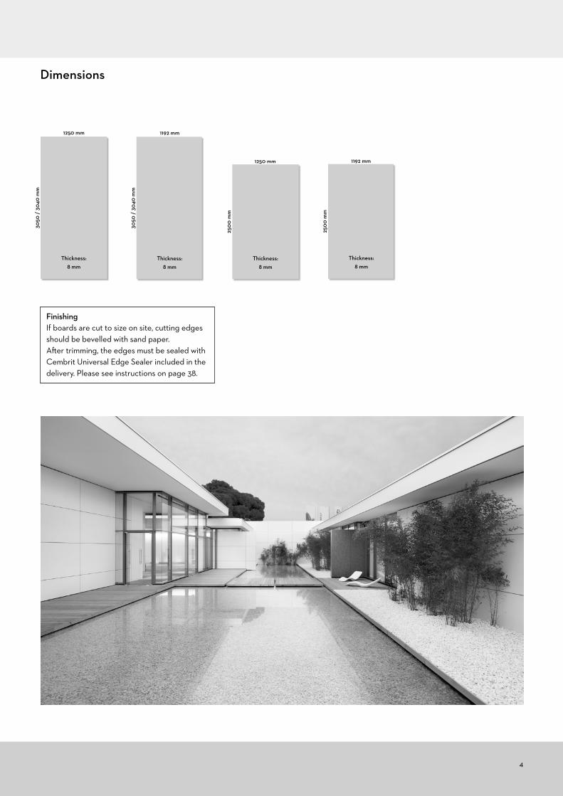
Dimensions
FinishingIf boards are cut to size on site, cutting edges should be bevelled with sand paper. After trimming, the edges must be sealed with Cembrit Universal Edge Sealer included in the delivery. Please see instructions on page 38.
1250 mm
Thickness: 8 mm
3050
/ 3
040
mm
1192 mm
2500
mm
Thickness: 8 mm
1192 mm
Thickness: 8 mm
3050
/ 3
040
mm
1250 mm
2500
mm
Thickness: 8 mm
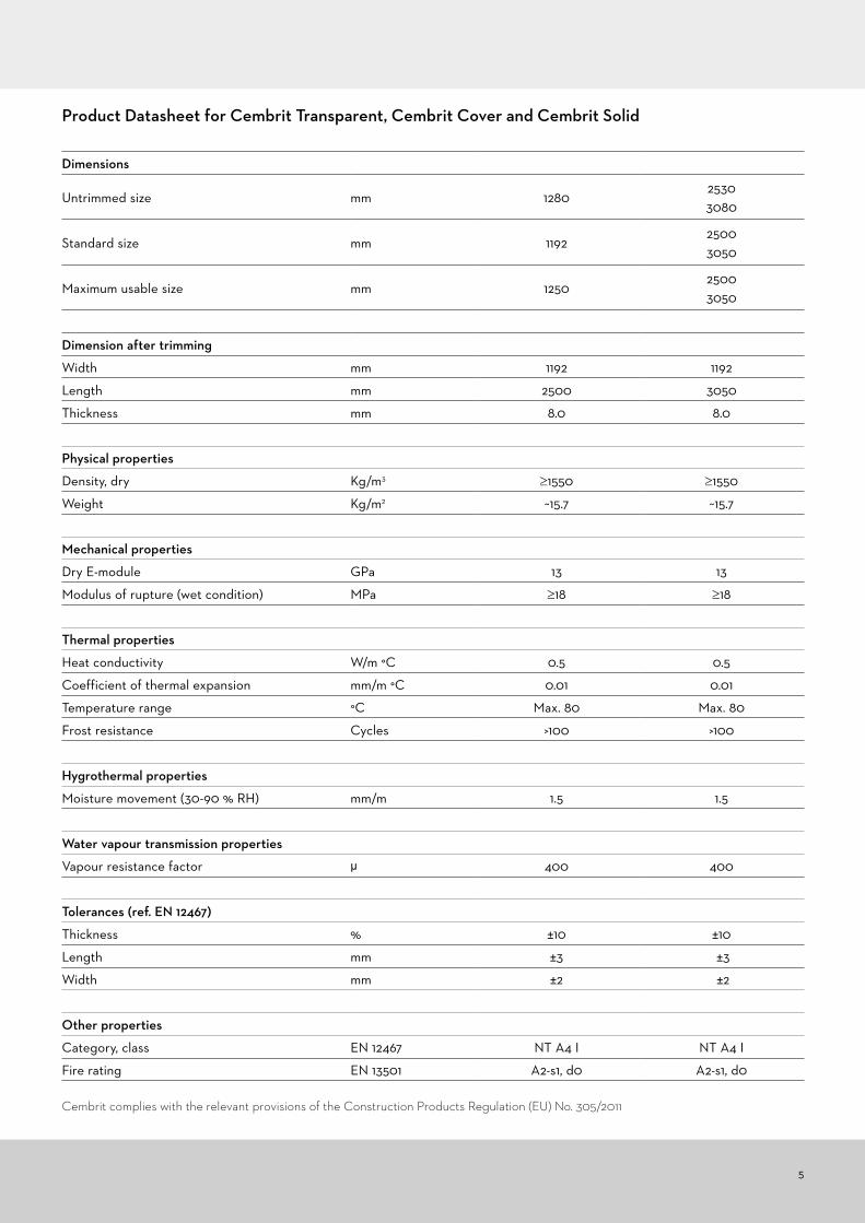
Product Datasheet for Cembrit Transparent, Cembrit Cover and Cembrit Solid
5
Cembrit complies with the relevant provisions of the Construction Products Regulation (EU) No. 305/2011
Dimensions
Untrimmed size mm 128025303080
Standard size mm 119225003050
Maximum usable size mm 125025003050
Dimension after trimming
Width mm 1192 1192
Length mm 2500 3050
Thickness mm 8.0 8.0
Physical properties
Density, dry Kg/m3 ≥1550 ≥1550
Weight Kg/m2 ~15.7 ~15.7
Mechanical properties
Dry E-module GPa 13 13
Modulus of rupture (wet condition) MPa ≥18 ≥18
Thermal properties
Heat conductivity W/m °C 0.5 0.5
Coefficient of thermal expansion mm/m °C 0.01 0.01
Temperature range °C Max. 80 Max. 80
Frost resistance Cycles >100 >100
Hygrothermal properties
Moisture movement (30-90 % RH) mm/m 1.5 1.5
Water vapour transmission properties
Vapour resistance factor µ 400 400
Tolerances (ref. EN 12467)
Thickness % ±10 ±10
Length mm ±3 ±±3
Width mm ±2 ±±2
Other properties
Category, class EN 12467 NT A4 I NT A4 I
Fire rating EN 13501 A2-s1, d0 A2-s1, d0

6
Accessories
Cembrit screws for fixing facade boards are made of stainless steel for achieving the highest corrosion resistance. Mush-room head wood screws 4.5 x 36/41 are used for wooden sub-constructions. The screws have a sharp point and a fast cut-ting thread which ensure firm fixing with a high pull-out value.
For steel sub-constructions with profiles ≥ 0.5 use Cembrit stainless steel self drilling and thread cutting screw 4.8 x 29 #1 with drilling capacity 0.5-1.5 mm.As an alternative use Cembrit stainless steel rivets 4.8x19 K14.
Furthermore, a washer is fixed on the tip of the screw to centralise it and to minimise penetration of water into the screw hole.
An alternative solution for wooden sub-constructions is the wing screw 4.9 x 38 which is equipped with a cutting bit and therefore requires no pre-drilling.
For securing the above mentioned free movement of the boards, it is of great importance that the drill hole in the aluminium sub-construction and the drill hole in the Cembrit board are concentric. This is ensured by using an assisting tool:
4.1 mm HSS drill for rivets in aluminium profiles (4.0 x 20 K14).4.9 mm HSS drill for rivets in steel profiles (4.8 x 19 K14).
All screws are delivered in their natural colour or powder painted in the same colour as the facade boards, and with a screw bit included ready to use.
On aluminium sub-constructions rivets are most commonly used. Cembrit rivets 4.0 x 20 K14 feature an aluminium body with a stainless steel mandrel. At fix-points, a sleeve is used to prevent movement of the board.
In order to allow the boards to move freely in sliding points when influenced by mois-ture and temperature changes, a stand-off head must be used ensuring a small space between the board and the rivet head. Drill holes are made correctly with the centering device.
Cembrit EPDM rubber underlay (3x90 mm and 3 x 30 mm) should always be placed under the Cembrit boards using mechanical fixing.
Cembrit boards can be fixed by gluing them to a sub-structure of planed impreg-nated wood or aluminium.
Note! The glue supplier’s recommenda-tions must be followed in this type of installation. For further information, please contact your local Cembrit representative.
Aluminium finishing for internal and exter-nal corners are available on request.
Special drill bit such as TCT Drill (7-8-9 mm) from Irwin Tools for pre-drilling in the facade boards.
19
1918
8
16
4 4
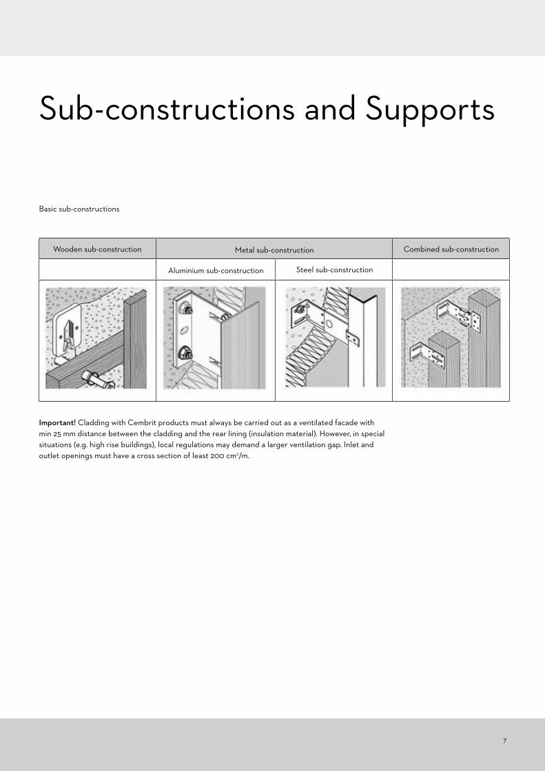
Important! Cladding with Cembrit products must always be carried out as a ventilated facade with min 25 mm distance between the cladding and the rear lining (insulation material). However, in special situations (e.g. high rise buildings), local regulations may demand a larger ventilation gap. Inlet and outlet openings must have a cross section of least 200 cm2/m.
Sub-constructions and Supports
7
Wooden sub-construction Metal sub-construction Combined sub-construction
Steel sub-constructionAluminium sub-construction
Basic sub-constructions

8
The installer is responsible for establishing a plane and strong sub-construction able to obtain the loads appearing on the actual facade and observing the fixing distances described in this manual.
Facade boards are normally installed in a vertical position on a vertical sub-structure. It is however possible to install the boards in a horizontal position. The guidelines for fixing are identical, which means the edge distances, corner distances etc. follow the sub-structure.
Front view vertical orientation
Front view horizontal orientation
Max support distance
Max fixing distance
Edge distance
Corner distance
k mm h, g mm a mm c mm
400-600** 350-600** 25-150 100-150*
**Depending on windload. Concact Cembrit for further details.
Max support distance
Max fixing distance
Edge distance
Corner distance
k mm h, g mm a mm c mm
400-600** 350-600** 25-150 100-150*
Fixing DetailsVertical board orientationInstallation on wood, vertical sub-constructionMax dimensions 8 x 1250 x 2500/3050 mmDrill hole in the boards: Ø8
Horizontal board orientation Installation on wood, vertical sub-constructionMax dimensions 8 x 1250 x 2500/3050 mmDrill hole in the boards: Ø8
*Overhang e.g. windows or foundations max 200 mm *Overhang e.g. windows or foundations max 200 mm**Depending on windload. Concact Cembrit for further details.
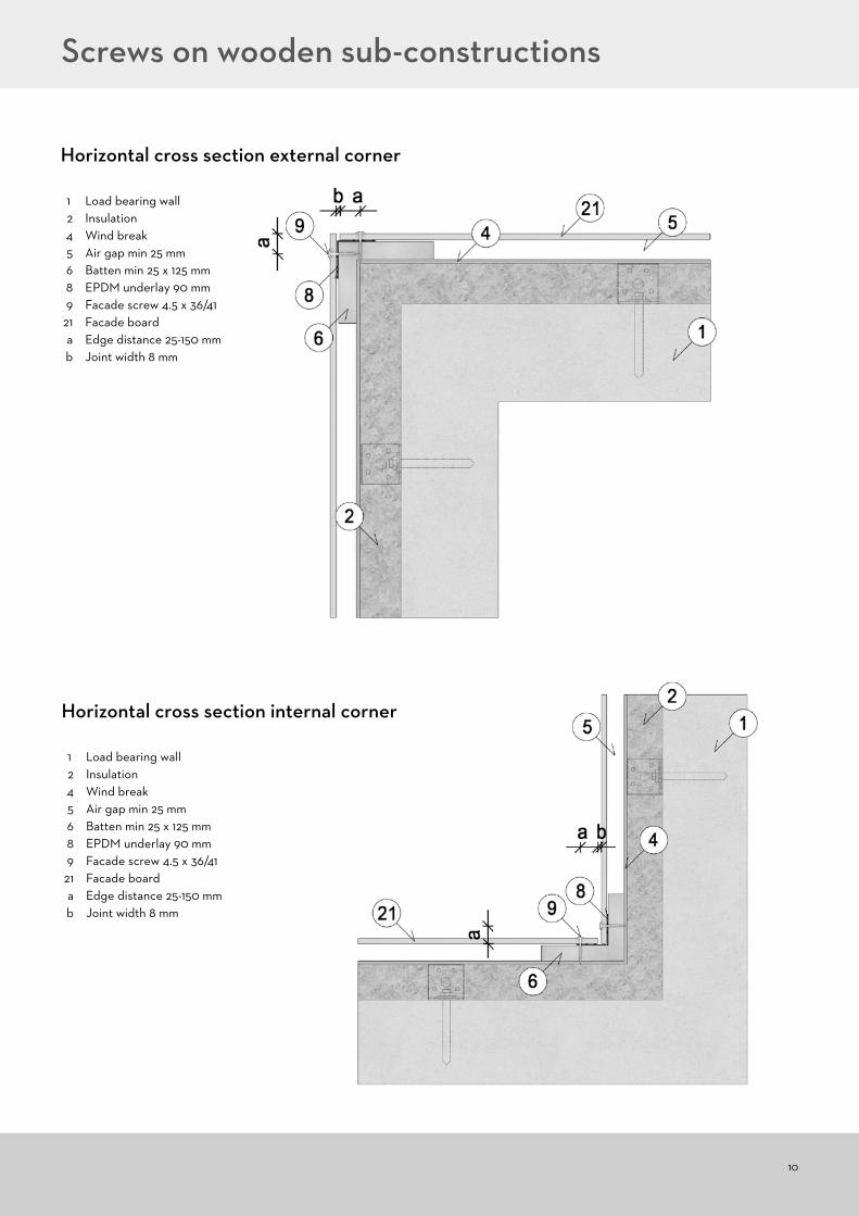
Screws on wooden sub-constructions

9
1 Load bearing wall2 Insulation4 Wind break5 Air gap min 25 mm6 Batten min 25 x 125 mm8 EPDM underlay 90 mm9 Facade screw 4.5 x 36/4121 Facade boarda Edge distance 25-150 mmb Joint width 8 mm
Horizontal cross section vertical joint
Fixing details screws on wood
Horizontal cross section intermediate support
Screws on wooden sub-constructions
1 Load bearing wall 2 Insulation 4 Wind break 5 Air gap min 25 mm 6 Batten min 25 x 62 mm 7 EPDM underlay 30 mm 9 Facade screw 4.5 x 36/41 21 Facade board
10
1 Load bearing wall 2 Insulation 4 Wind break 5 Air gap min 25 mm 6 Batten min 25 x 125 mm 8 EPDM underlay 90 mm 9 Facade screw 4.5 x 36/41 21 Facade board a Edge distance 25-150 mm b Joint width 8 mm
1 Load bearing wall 2 Insulation 4 Wind break 5 Air gap min 25 mm 6 Batten min 25 x 125 mm 8 EPDM underlay 90 mm 9 Facade screw 4.5 x 36/41 21 Facade board a Edge distance 25-150 mm b Joint width 8 mm
Horizontal cross section external corner
Horizontal cross section internal corner
Screws on wooden sub-constructions
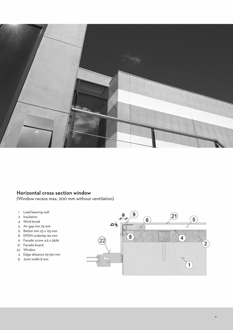
1 Load bearing wall 2 Insulation 4 Wind break 5 Air gap min 25 mm 6 Batten min 25 x 125 mm 8 EPDM underlay 90 mm 9 Facade screw 4.5 x 36/41 21 Facade board 22 Window a Edge distance 25-150 mm b Joint width 8 mm
Horizontal cross section window (Window recess max. 200 mm without ventilation)
11
12
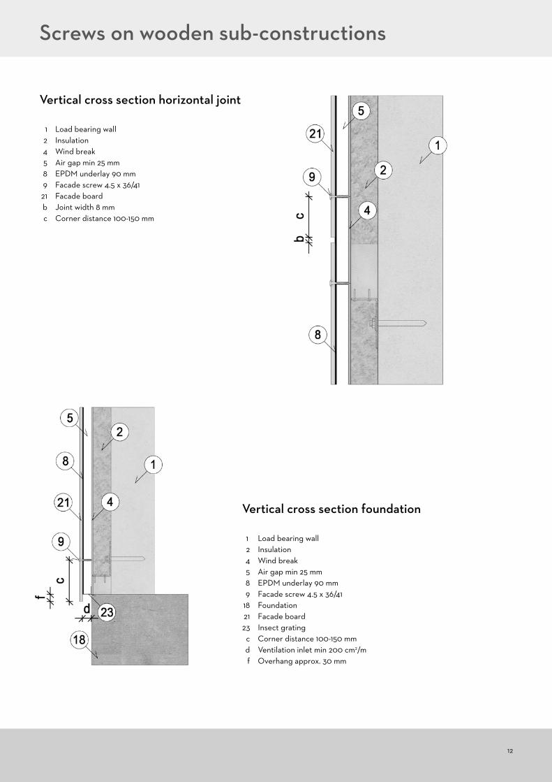
1 Load bearing wall 2 Insulation 4 Wind break 5 Air gap min 25 mm 8 EPDM underlay 90 mm 9 Facade screw 4.5 x 36/41 21 Facade board b Joint width 8 mm c Corner distance 100-150 mm
Vertical cross section horizontal joint
1 Load bearing wall 2 Insulation 4 Wind break 5 Air gap min 25 mm 8 EPDM underlay 90 mm 9 Facade screw 4.5 x 36/41 18 Foundation 21 Facade board 23 Insect grating c Corner distance 100-150 mm d Ventilation inlet min 200 cm2/m f Overhang approx. 30 mm
Vertical cross section foundation
Screws on wooden sub-constructions
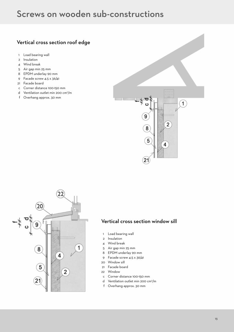
1 Load bearing wall 2 Insulation 4 Wind break 5 Air gap min 25 mm 8 EPDM underlay 90 mm 9 Facade screw 4.5 x 36/41 21 Facade board c Corner distance 100-150 mm d Ventilation outlet min 200 cm2/m f Overhang approx. 30 mm
1 Load bearing wall 2 Insulation 4 Wind break 5 Air gap min 25 mm 8 EPDM underlay 90 mm 9 Facade screw 4.5 x 36/41 20 Window sill 21 Facade board 22 Window c Corner distance 100-150 mm d Ventilation outlet min 200 cm2/m f Overhang approx. 30 mm
Vertical cross section roof edge
Vertical cross section window sill
13
Screws on wooden sub-constructions

14
1 Load bearing wall 2 Insulation 4 Wind break 5 Air gap min 25 mm 7 EPDM underlay 90 mm 9 Facade screw 4.5 x 36/41 21 Facade board 22 Window 23 Insect grating c Corner distance 100-150 mm d Ventilation inlet min 200 cm2/m f Overhang approx. 30 mm
Internal corner External corner
Vertical cross section window upper edge(Window recess max 200 mm without ventilation)
Screws on wooden sub-constructions
CeilingFacade boards may also be installed as under-cladding or ceiling. The installation principles are the same as for vertical installation. Edge distance for screws 25 mm. Corner distance 100 mm. Max support and fixing distances 400 mm.
100 mm
400 mm25 mm

Front view Ceiling
15
In order to achieve a correct and safe aluminium sub-construction, the supplier of the system should be consulted. However, there are a few rules to consider when it comes to the functionality of the facade boards:• Length of the aluminium profiles is minimised to 3000 mm (one storey)• The aluminium profiles must be fixed with one fix-point at the middle or the upper end and all other fixations as sliding points• All joints of the aluminium profiles must be aligned so they can be followed by joints of the facade boards. A board must never cross an
aluminium profile joint and be fixed to two separate aluminium profiles across a joint• The facade boards must be fixed with a fix-point in the middle of the board. All other fixations are sliding points. In case of two intermedi-
ate supporting profiles, two fix-points at the same horizontal level are allowed• Every 12 m of the facade a double framing must be installed in order to create a dilatation joint.• Important! With installation with rivets, begin with the fix-points, followed by the sliding points above and finally the sliding points below.
Rivets on aluminium
Fix Point Sliding point
Max support distance
Max fixing distance
Edge distance
Corner distance
k mm h, g mm a mm c mm
400-600** 400-600** 30-150 100-150*
*Overhang e.g. windows or foundations max 200 mm**Depending on windload. Concact Cembrit for further details.
Fixing detailsVertical board orientation Installation with rivets on aluminium, vertical sub-constructionMax dimensions 8 x 1250 x 2500/3050 mm Drill hole in the boards: Ø9
100 mm
400 mm30 mm
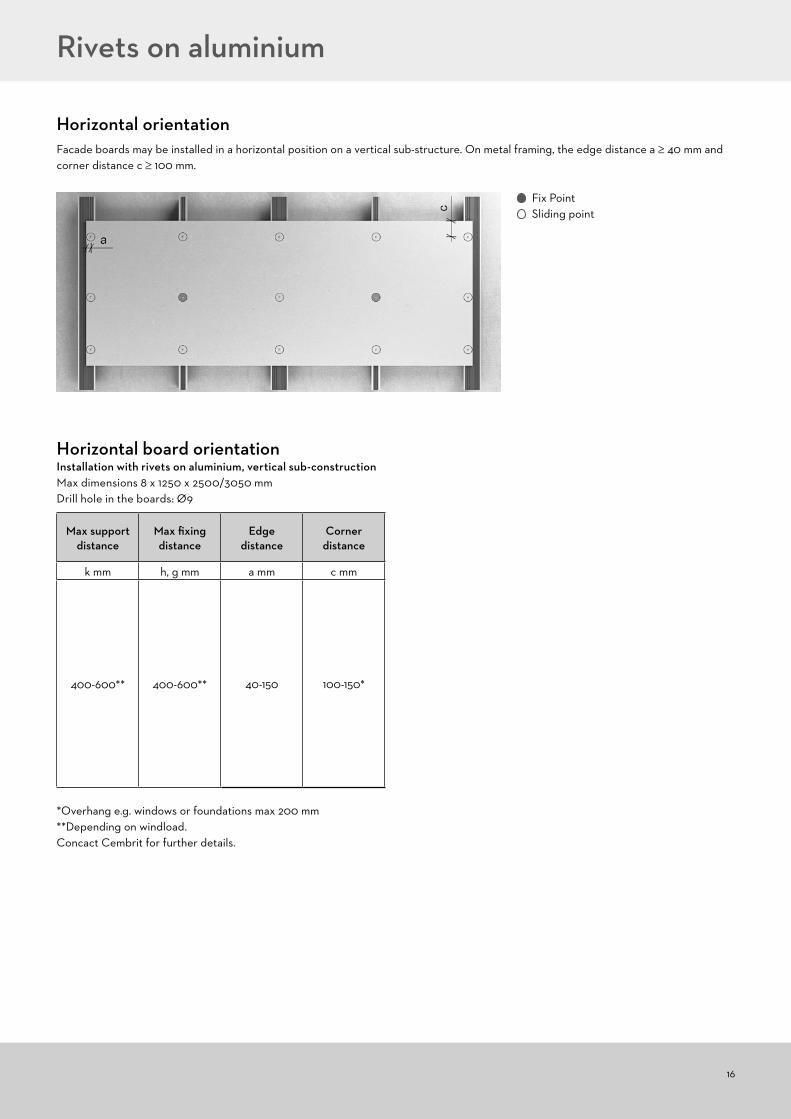
Horizontal orientation
16
Facade boards may be installed in a horizontal position on a vertical sub-structure. On metal framing, the edge distance a ≥ 40 mm and corner distance c ≥ 100 mm.
Fix Point Sliding point
Max support distance
Max fixing distance
Edge distance
Corner distance
k mm h, g mm a mm c mm
400-600** 400-600** 40-150 100-150*
*Overhang e.g. windows or foundations max 200 mm**Depending on windload. Concact Cembrit for further details.
Horizontal board orientationInstallation with rivets on aluminium, vertical sub-constructionMax dimensions 8 x 1250 x 2500/3050 mmDrill hole in the boards: Ø9
Rivets on aluminium

17
Rivets on aluminium
1 Load bearing wall 3 Insulation 5 Air gap min 25 mm 8 EPDM underlay 90 mm (optional) 11 Rivet 4.0x20 K14 16 Aluminium frame system 21 Facade board a Edge distance min 30/40 mm b Joint width 8 mm
Horizontal cross section vertical joint
1 Load bearing wall 3 Insulation 5 Air gap min 25 mm 7 EPDM underlay 30 mm (optionel) 11 Rivet 4.0x20 K14 16 Aluminium frame system 21 Facade board
Horizontal cross section intermediate support

18
Rivets on aluminium
1 Load bearing wall 3 Insulation 5 Air gap min 25 mm 7 EPDM underlay 30 mm (optional) 8 EPDM underlay 90 mm (optional) 11 Rivet 4.0x20 K14 16 Aluminium frame system 17 Aluminium angle 60x60x2 mm 21 Facade board a Edge distance min 30/40 mm b Joint width 8 mm e Dist. to wall fixing max 200 mm
Horizontal cross section external corner
1 Load bearing wall 3 Insulation 5 Air gap min 25 mm 7 EPDM underlay 30 mm (optional) 8 EPDM underlay 90 mm (optional) 11 Rivet 4.0x20 K14 16 Aluminium frame system 17 Aluminium angle 60x60x2 mm 21 Facade board a Edge distance min 30/40 mm b Joint width 8 mm
Horizontal cross section internal corner

19
Rivets on aluminium
Vertical cross section horizontal joint
1 Load bearing wall 3 Insulation 5 Air gap min 25 mm 8 EPDM underlay 90 mm (optional) 10 Fixing point profile/bracket 11 Rivet 4.0x20 K14 15 Aluminium profile 16 Aluminium frame system 21 Facade board b Joint width 8 mm c Corner distance min 100 mm
Note! Boards must never be fixed to two separate profiles!
1 Load bearing wall 3 Insulation 5 Air gap min 25 mm 7 EPDM underlay 30 mm (optional) 8 EPDM underlay 90 mm (optional) 11 Rivet 4.0x20 K14 16 Aluminium frame system 17 Aluminium angle 60x60x2 mm 21 Facade board 22 Window a Edge distance min 30/40 mm b Joint width 8 mm
Horizontal cross section window(Window recess max 200 mm without ventilation)
20
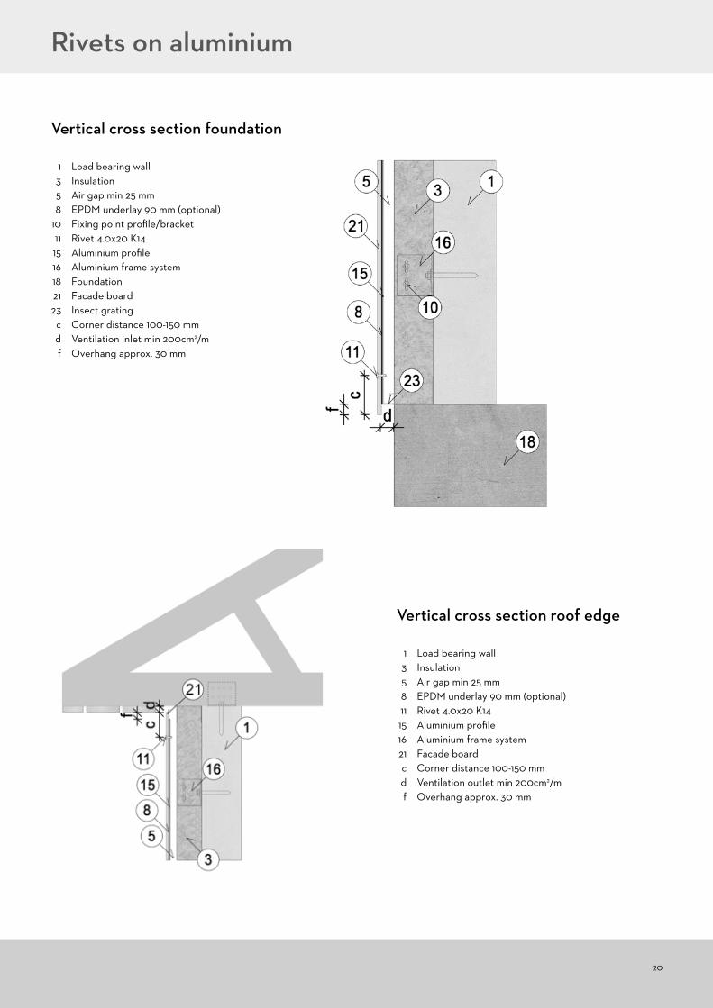
Rivets on aluminium
1 Load bearing wall 3 Insulation 5 Air gap min 25 mm 8 EPDM underlay 90 mm (optional) 10 Fixing point profile/bracket 11 Rivet 4.0x20 K14 15 Aluminium profile 16 Aluminium frame system 18 Foundation 21 Facade board 23 Insect grating c Corner distance 100-150 mm d Ventilation inlet min 200cm2/m f Overhang approx. 30 mm
Vertical cross section foundation
1 Load bearing wall 3 Insulation 5 Air gap min 25 mm 8 EPDM underlay 90 mm (optional) 11 Rivet 4.0x20 K14 15 Aluminium profile 16 Aluminium frame system 21 Facade board c Corner distance 100-150 mm d Ventilation outlet min 200cm2/m f Overhang approx. 30 mm
Vertical cross section roof edge
21
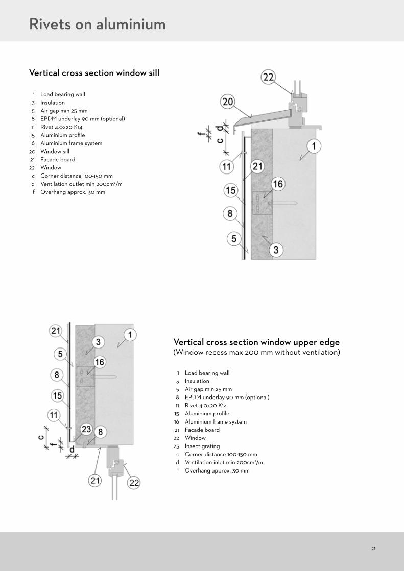
Rivets on aluminium
1 Load bearing wall 3 Insulation 5 Air gap min 25 mm 8 EPDM underlay 90 mm (optional) 11 Rivet 4.0x20 K14 15 Aluminium profile 16 Aluminium frame system 21 Facade board 22 Window 23 Insect grating c Corner distance 100-150 mm d Ventilation inlet min 200cm2/m f Overhang approx. 30 mm
Vertical cross section window upper edge(Window recess max 200 mm without ventilation)
1 Load bearing wall 3 Insulation 5 Air gap min 25 mm 8 EPDM underlay 90 mm (optional) 11 Rivet 4.0x20 K14 15 Aluminium profile 16 Aluminium frame system 20 Window sill 21 Facade board 22 Window c Corner distance 100-150 mm d Ventilation outlet min 200cm2/m f Overhang approx. 30 mm
Vertical cross section window sill

22
Screws and rivets on steel sub-construction
In order to achieve a correct and safe steel sub-construction, the supplier of the system should be consulted. However, there are a few rules to consider when it comes to the functionality of the facade boards:
• Length of the steel profiles is maximum 3000 mm (one storey)• The steel profiles must be fixed with one fix-point at the middle or the upper end and all other fixations as sliding points• All joints of the steel profiles must be aligned allowing them to be followed by joints of the facade boards. A board must never cross a
joint in the steel profiles. A board must never cross a steel profile joint and be fixed to two separate steel profiles across a joint• The facade boards must be fixed with a fix-point in the middle of the board. All other fixations are sliding points. In case of two intermedi-
ate supporting profiles, two fix-points at the same horizontal level are allowed• Every 12 m of the facade a double framing must be installed in order to create a dilatation joint.• Important! Fasten the boards at the fix-point(s), followed by the sliding points above and finally the sliding points below.(The following illustrations show installation with screws – details are similar for rivets)
Fix Point Sliding point
Max support distance
Max fixing distance
Edgedistance
Corner distance
k mm h, g mm a mm c mm
400-600** 400-600** 30-150 100-150*
Vertical board orientation Installation on steel, vertical sub-constructionMax dimensions 8 x 1250 x 2500/3050 mmDrill hole in the boards: Ø8
*Overhang e.g. windows or foundations max 200 mm**Depending on windload. Concact Cembrit for further details.
Fixing details
Ceiling
100 mm
400 mm30 mm
23
Screws and rivets on steel sub-construction
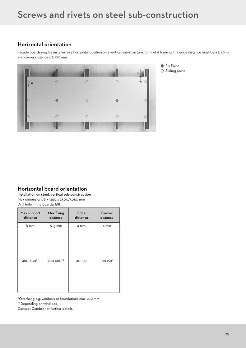
Fix Point Sliding point
Horizontal orientationFacade boards may be installed in a horizontal position on a vertical sub-structure. On metal framing, the edge distance must be a ≥ 40 mm and corner distance c ≥ 100 mm.
Max support distance
Max fixing distance
Edgedistance
Corner distance
k mm h, g mm a mm c mm
400-600** 400-600** 40-150 100-150*
Horizontal board orientation Installation on steel, vertical sub-constructionMax dimensions 8 x 1250 x 2500/3050 mmDrill hole in the boards: Ø8
*Overhang e.g. windows or foundations max 200 mm**Depending on windload. Concact Cembrit for further details.
24
Screws and rivets on steel sub-construction
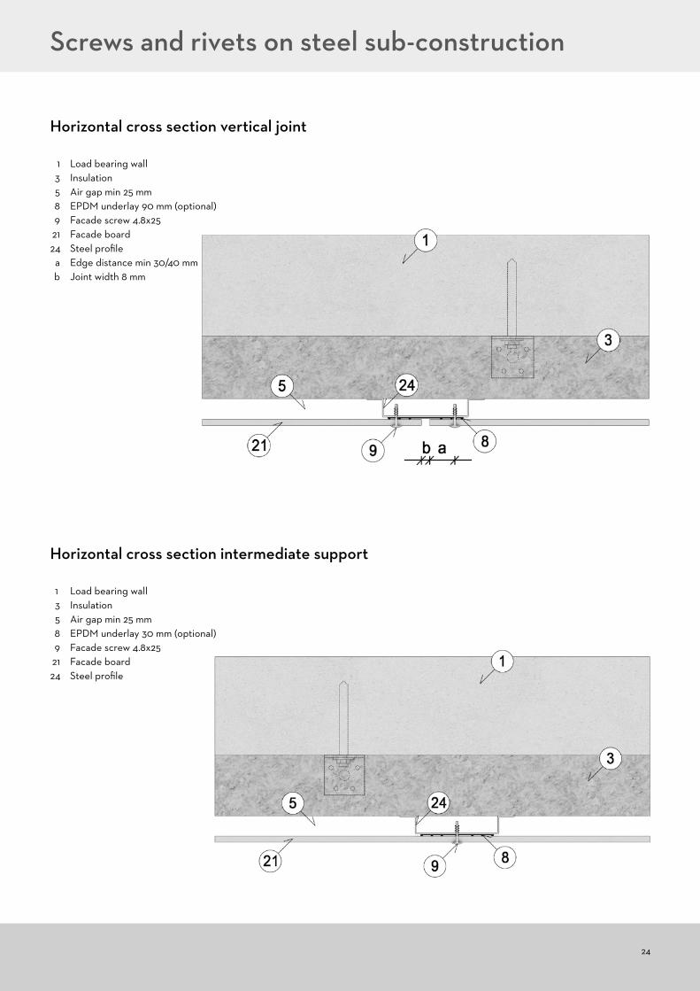
1 Load bearing wall 3 Insulation 5 Air gap min 25 mm 8 EPDM underlay 90 mm (optional) 9 Facade screw 4.8x25 21 Facade board 24 Steel profile a Edge distance min 30/40 mm b Joint width 8 mm
Horizontal cross section vertical joint
1 Load bearing wall 3 Insulation 5 Air gap min 25 mm 8 EPDM underlay 30 mm (optional) 9 Facade screw 4.8x25 21 Facade board 24 Steel profile
Horizontal cross section intermediate support

25
Screws and rivets on steel sub-construction
1 Load bearing wall 3 Insulation 5 Air gap min 25 mm 7 EPDM underlay 30 mm (optional) 8 EPDM underlay 90 mm (optional) 9 Facade screw 4.8x25 21 Facade board 24 Steel profile a Edge distance min 30/40 mm b Joint width 8 mm
Horizontal cross section internal corner
1 Load bearing wall 3 Insulation 5 Air gap min 25 mm 7 EPDM underlay 30 mm (optional) 8 EPDM underlay 90 mm (optional) 9 Facade screw 4.8x25 21 Facade board 24 Steel profile a Edge distance min 30/40 mm b Joint width 8 mm
Horizontal cross section external corner

26
Screws and rivets on steel sub-construction
1 Load bearing wall 3 Insulation 5 Air gap min 25 mm 8 EPDM underlay 90 mm (optional) 9 Facade screw 4.8x25 21 Facade board22 Window 24 Steel profile a Edge distance min 30/40 mm b Joint width 8 mm
Horizontal cross section window(Window recess max 200 mm without ventilation)
1 Load bearing wall 3 Insulation 5 Air gap min 25 mm 8 EPDM underlay 90 mm (optional) 9 Facade screw 4.8x25 21 Facade board 24 Steel profile b Joint width 8 mm c Corner distance min 100 mm
Vertical cross section horizontal joint

27
Screws and rivets on steel sub-construction
1 Load bearing wall 3 Insulation 5 Air gap min 25 mm 8 EPDM underlay 90 mm (optional) 9 Facade screw 4.8x25 18 Foundation 21 Facade board 23 Insect grating 24 Steel profile c Corner distance 100-150 mm d Ventilation inlet min 200 cm2/m f Overhang approx. 30 mm
Vertical cross section foundation
1 Load bearing wall 3 Insulation 5 Air gap min 25 mm 8 EPDM underlay 90 mm (optional) 9 Facade screw 4.8x25 19 Eave 21 Facade board 24 Steel profile c Corner distance 100-150 mm d Ventilation outlet min 200 cm2/m f Overhang approx. 30 mm
Vertical cross section roof edge

28
Screws and rivets on steel sub-construction
1 Load bearing wall 3 Insulation 5 Air gap min 25 mm 8 EPDM underlay 90 mm (optional) 9 Facade screw 4.8x25 20 Window sill 21 Facade board 22 Window 24 Steel profile c Corner distance 100-150 mm d Ventilation outlet min 200 cm2/m f Overhang approx. 30 mm
Vertical cross section window sill
1 Load bearing wall 3 Insulation 5 Air gap min 25 mm 8 EPDM underlay 90 mm (optional) 9 Facade screw 4.8x25 21 Facade board 22 Window 23 Insect grating 24 Steel profile c Corner distance 100-150 mm d Ventilation inlet min 200 cm2/m f Overhang approx. 30 mm
Vertical cross section window upper edge(Window recess max 200 mm without ventilation)
29
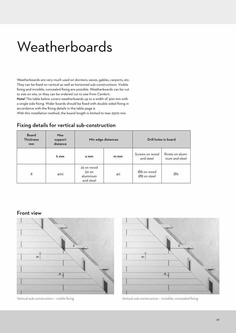
Weatherboards are very much used on dormers, eaves, gables, carports, etc. They can be fixed on vertical as well as horizontal sub-constructions. Visible fixing and invisible, concealed fixing are possible. Weatherboards can be cut to size on site, or they can be ordered cut to size from Cembrit.Note! The table below covers weatherboards up to a width of 300 mm with a single side fixing. Wider boards should be fixed with double sided fixing in accordance with the fixing details in the table page 9.With this installation method, the board length is limited to max 2500 mm.
Weatherboards
BoardThickness
mm
Max support distance
Min edge distances Drill holes in board
k mm a mm m mm Screws on wood and steel
Rivets on alumi-nium and steel
8 400
25 on wood30 on
aluminiumand steel
40Ø8 on woodØ8 on steel
Ø9
Front view
Fixing details for vertical sub-construction
Vertical sub-construction – visible fixing Vertical sub-construction – invisible, concealed fixing
30
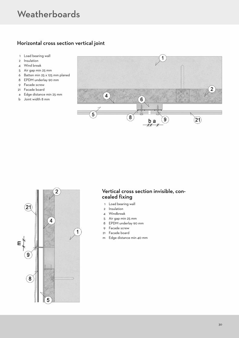
1 Load bearing wall 2 Insulation 4 Windbreak 5 Air gap min 25 mm 8 EPDM underlay 90 mm 9 Facade screw 21 Facade board m Edge distance min 40 mm
Vertical cross section invisible, con-cealed fixing
Weatherboards
Horizontal cross section vertical joint
1 Load bearing wall 2 Insulation 4 Wind break 5 Air gap min 25 mm 6 Batten min 25 x 125 mm planed 8 EPDM underlay 90 mm 9 Facade screw 21 Facade board a Edge distance min 25 mm b Joint width 8 mm
31
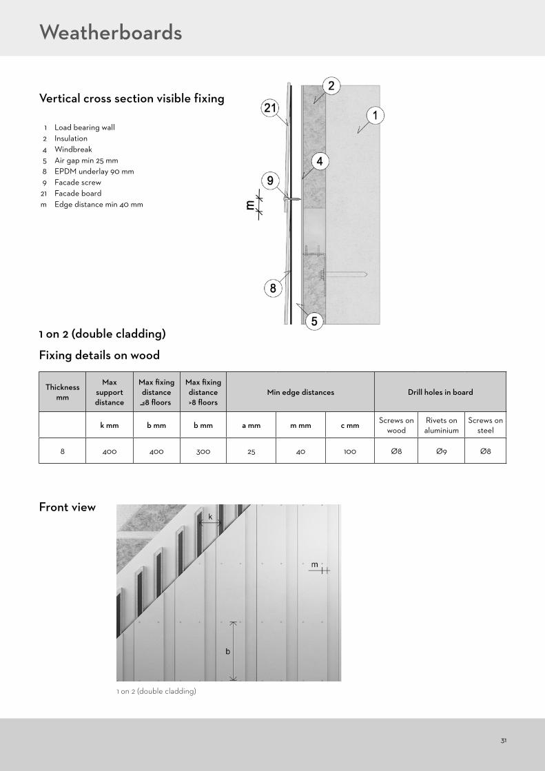
Fixing details on wood
1 on 2 (double cladding)
Thickness mm
Max support distance
Max fixing distance <8 floors
Max fixing distance >8 floors
Min edge distances Drill holes in board
k mm b mm b mm a mm m mm c mm Screws on wood
Rivets on aluminium
Screws on steel
8 400 400 300 25 40 100 Ø8 Ø9 Ø8
1 Load bearing wall 2 Insulation 4 Windbreak 5 Air gap min 25 mm 8 EPDM underlay 90 mm 9 Facade screw 21 Facade board m Edge distance min 40 mm
Vertical cross section visible fixing
Front view
Weatherboards
1 on 2 (double cladding)
32
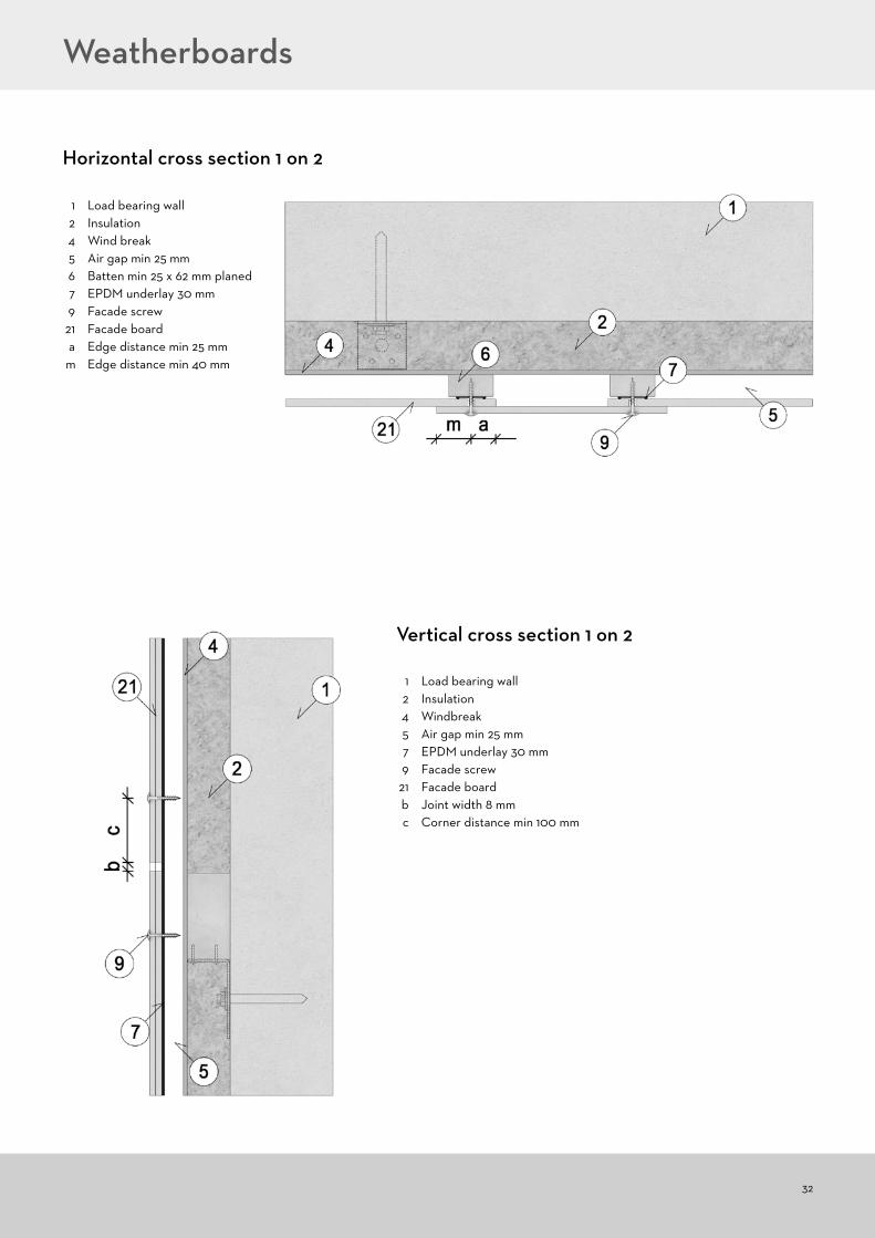
Horizontal cross section 1 on 2
1 Load bearing wall 2 Insulation 4 Wind break 5 Air gap min 25 mm 6 Batten min 25 x 62 mm planed 7 EPDM underlay 30 mm 9 Facade screw 21 Facade board a Edge distance min 25 mm m Edge distance min 40 mm
1 Load bearing wall 2 Insulation 4 Windbreak 5 Air gap min 25 mm 7 EPDM underlay 30 mm 9 Facade screw 21 Facade board b Joint width 8 mm c Corner distance min 100 mm
Vertical cross section 1 on 2
Weatherboards
33
Storing, Handling and Processing
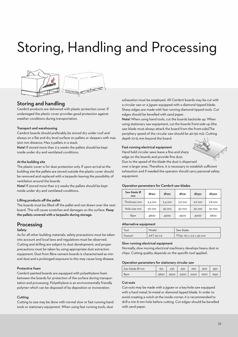
Storing and handlingCembrit products are delivered with plastic protection cover. If undamaged the plastic cover provides good protection against weather conditions during transportation.
Transport and warehousingCembrit boards should preferably be stored dry under roof and always on a flat and dry level surface on pallets or sleepers with max 500 mm distance. Max 5 pallets in a stack.Note! If stored more than 2-3 weeks the pallets should be kept inside under dry and ventilated conditions.
At the building siteThe plastic cover is for dust protection only. If upon arrival at the building site the pallets are stored outside the plastic cover should be removed and replaced with a tarpaulin leaving the possibility of ventilation around the boards. Note! If stored more than 2-3 weeks the pallets should be kept inside under dry and ventilated conditions.
Lifting products off the palletThe boards must be lifted off the pallet and not drawn over the next board. This will cause scratches and damages on the surface. Keep the pallets covered with a tarpaulin during storage.
ProcessingSafetyAs for all other building materials, safety precautions must be taken into account and local laws and regulations must be observed. Cutting and drilling are subject to dust development, and proper precautions must be taken by using appropriate dust extraction equipment. Dust from fibre-cement boards is characterised as min-eral dust and a prolonged exposure to this may cause lung disease.
Protective foamCembrit painted boards are equipped with polyethylene foam between the boards for protection of the surface during transpor-tation and processing. Polyethylene is an environmentally friendly polymer which can be disposed of by deposition or incineration.
CuttingCutting to size may be done with normal slow or fast running hand tools or stationary equipment. When using fast running tools, dust
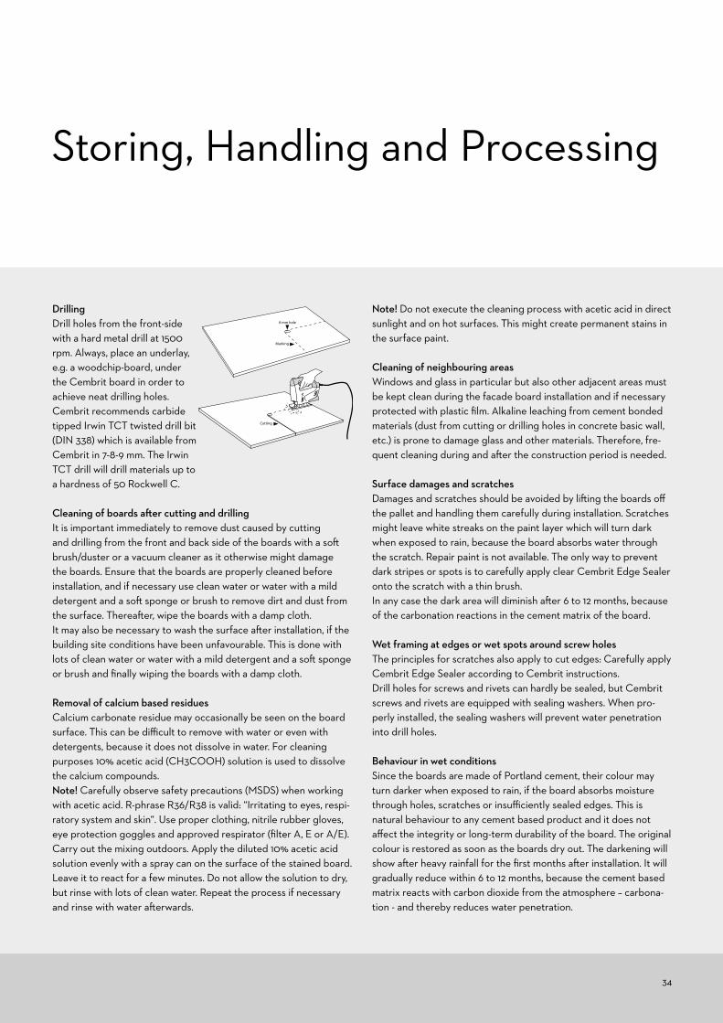
exhaustion must be employed. All Cembrit boards may be cut with a circular saw or a jigsaw equipped with a diamond tipped blade. Sharp edges are made with fast running diamond tipped tools. Cut edges should be bevelled with sand paper.Note! When using hand tools, cut the boards backside up. When using stationary saw equipment, cut the boards front-side up (the saw blade must always attack the board from the front-side).The periphery speed of the circular saw should be 40-50 m/s. Cutting depth 10-15 mm beyond the board.
Fast running electrical equipmentHand held circular saws leave a fine and sharp edge on the boards and provide fine dust. Due to the speed of the blade the dust is dispersed over a larger area. Therefore, it is necessary to establish sufficient exhaustion and if needed the operator should carry personal safety equipment.
Operation parameters for Cembrit saw blades
Alternative equipment
Slow running electrical equipmentNormally, slow moving electrical machinery develops heavy dust or chips. Cutting quality depends on the specific tool applied.
Operation parameters for stationary circular saw
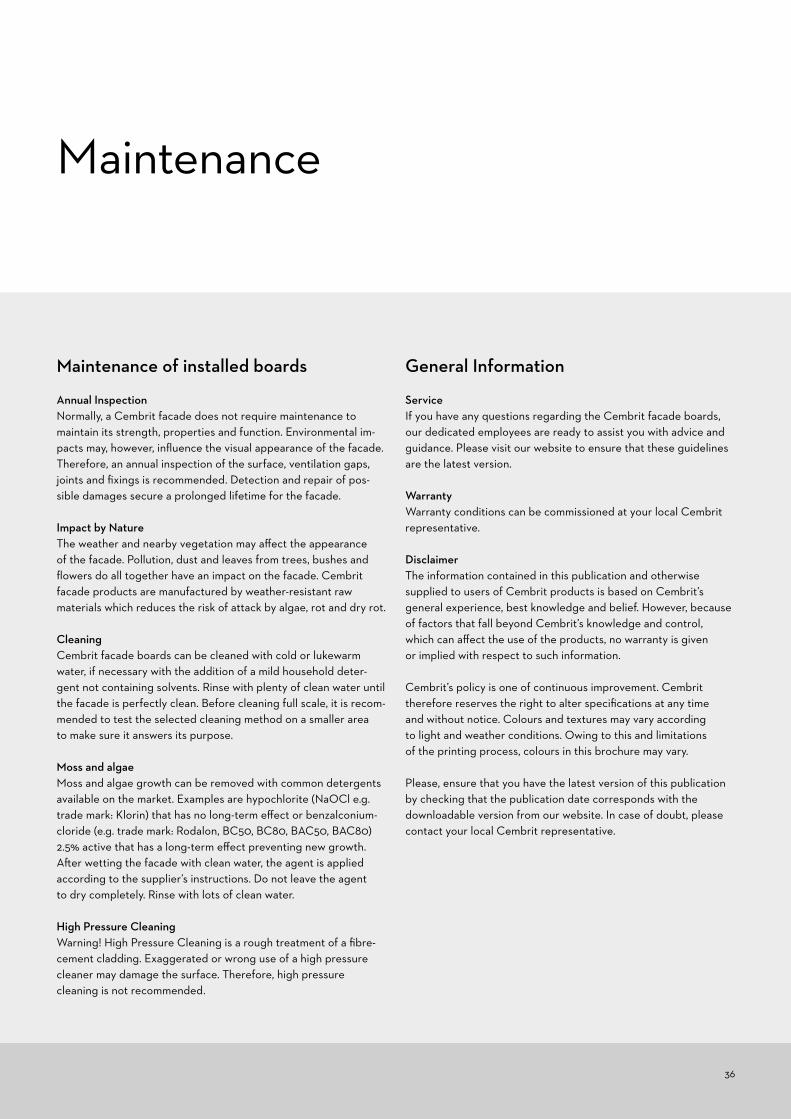
Cut-outsCut-outs may be made with a jigsaw or a key-hole saw equipped with a hard metal, bi-metal or diamond tipped blade. In order to avoid creating a notch at the inside corner, it is recommended to drill a min 8 mm hole before cutting. Cut edges should be bevelled with sand paper.
Saw blade Ø mm Ø160 Ø190 Ø216 Ø250 Ø300
Thickness mm 2.4 mm 2.4 mm 2.6 mm 2.6 mm 2.8 mm
Hole size mm 20 mm 30 mm 30 mm 30 mm 30 mm
Rpm 4800 4000 3500 3000 2800
Saw blade Ø mm 150 230 250 260 300 350
Rpm 3800 2500 2300 2200 1900 1650
Tool Model Saw blade
Festool AXT 50 LA TF56, 170 x 2.0 x 30 mm
34
Storing, Handling and Processing
DrillingDrill holes from the front-side with a hard metal drill at 1500 rpm. Always, place an underlay, e.g. a woodchip-board, under the Cembrit board in order to achieve neat drilling holes.Cembrit recommends carbide tipped Irwin TCT twisted drill bit (DIN 338) which is available from Cembrit in 7-8-9 mm. The Irwin TCT drill will drill materials up to a hardness of 50 Rockwell C. Cleaning of boards after cutting and drillingIt is important immediately to remove dust caused by cutting and drilling from the front and back side of the boards with a soft brush/duster or a vacuum cleaner as it otherwise might damage the boards. Ensure that the boards are properly cleaned before installation, and if necessary use clean water or water with a mild detergent and a soft sponge or brush to remove dirt and dust from the surface. Thereafter, wipe the boards with a damp cloth.It may also be necessary to wash the surface after installation, if the building site conditions have been unfavourable. This is done with lots of clean water or water with a mild detergent and a soft sponge or brush and finally wiping the boards with a damp cloth.
Removal of calcium based residuesCalcium carbonate residue may occasionally be seen on the board surface. This can be difficult to remove with water or even with detergents, because it does not dissolve in water. For cleaning purposes 10% acetic acid (CH3COOH) solution is used to dissolve the calcium compounds.Note! Carefully observe safety precautions (MSDS) when working with acetic acid. R-phrase R36/R38 is valid: “Irritating to eyes, respi-ratory system and skin“. Use proper clothing, nitrile rubber gloves, eye protection goggles and approved respirator (filter A, E or A/E). Carry out the mixing outdoors. Apply the diluted 10% acetic acid solution evenly with a spray can on the surface of the stained board. Leave it to react for a few minutes. Do not allow the solution to dry, but rinse with lots of clean water. Repeat the process if necessary and rinse with water afterwards.
Note! Do not execute the cleaning process with acetic acid in direct sunlight and on hot surfaces. This might create permanent stains in the surface paint.
Cleaning of neighbouring areasWindows and glass in particular but also other adjacent areas must be kept clean during the facade board installation and if necessary protected with plastic film. Alkaline leaching from cement bonded materials (dust from cutting or drilling holes in concrete basic wall, etc.) is prone to damage glass and other materials. Therefore, fre-quent cleaning during and after the construction period is needed.
Surface damages and scratchesDamages and scratches should be avoided by lifting the boards off the pallet and handling them carefully during installation. Scratches might leave white streaks on the paint layer which will turn dark when exposed to rain, because the board absorbs water through the scratch. Repair paint is not available. The only way to prevent dark stripes or spots is to carefully apply clear Cembrit Edge Sealer onto the scratch with a thin brush.In any case the dark area will diminish after 6 to 12 months, because of the carbonation reactions in the cement matrix of the board.
Wet framing at edges or wet spots around screw holesThe principles for scratches also apply to cut edges: Carefully apply Cembrit Edge Sealer according to Cembrit instructions.Drill holes for screws and rivets can hardly be sealed, but Cembrit screws and rivets are equipped with sealing washers. When pro-perly installed, the sealing washers will prevent water penetration into drill holes.
Behaviour in wet conditionsSince the boards are made of Portland cement, their colour may turn darker when exposed to rain, if the board absorbs moisture through holes, scratches or insufficiently sealed edges. This is natural behaviour to any cement based product and it does not affect the integrity or long-term durability of the board. The original colour is restored as soon as the boards dry out. The darkening will show after heavy rainfall for the first months after installation. It will gradually reduce within 6 to 12 months, because the cement based matrix reacts with carbon dioxide from the atmosphere – carbona-tion - and thereby reduces water penetration.
Cutting
8 mm hole
Marking

35
Finishing of edges with Cembrit Universal Edge Sealer
Product typeSolvent based clear edge sealer for Cembrit Solid, Cembrit Trans-parent and Cembrit Cover.
UsageCembrit Universal Edge Sealer must always be used to protect all unpainted edges of Cembrit Solid, Cembrit Transparent and Cembrit Cover fibre cement boards. Factory cut edges are always painted.Only Cembrit Universal Edge Sealer should be used to protect the edges of Cembrit facade boards.
Surface preparationAfter cutting, edges must be treated immediately with Cembrit Universal Edge Sealer. Board must be dry. Edges should be bevelled with fine grade sand paper and must be thoroughly cleaned from dust and dirt before applying the edge sealer.
Application conditionsBoard temperature and ambient temperature should be +5 °C - +30 °C and relative humidity <85 % . Process temperature must be min +5 °C.
Storing, Handling and Processing
Application1. Shake the edge sealer can well before filling the applicator with edge sealer. Shake the filled applicator also before use if applicator unused for a while.2. Remove the protective cap3. Position the applicator horizontally4. Place the sponge parallel to the board edge and run twice along the edge with a moderate pressure. Note! Carefully prevent the edge sealer to flow onto the front side of the board. Excess edge sealer on front side of the board must be wiped off immediately with a clean cloth5. Check that the liquid has been applied over the entire edge surface6. Close the applicator with the cap when interrupting the job7. Replace the sponge when necessary
The boards can be handled 2 minutes after application of the edge sealer.
CleaningNo cleaning of equipment necessary. Unintended spillage can be cleaned with white spirit.
StorageAlways keep the containers tightly closed and avoid direct exposure to sunlight. Store in a dry, cool and well ventilated place. Keep away from sources of ignition. No smoking.Shelf life is 6 months in unopened original packaging at cool tempe-ratures. Can be stored at temperatures from -20 to +30 °C.
DisposalDisposal of the edge sealer must be in compliance with local and national regulations. Please refer to Material Safety Data Sheet.
Safety measuresPlease refer to Material Safety Data Sheet
36
Maintenance of installed boards
Annual InspectionNormally, a Cembrit facade does not require maintenance to maintain its strength, properties and function. Environmental im-pacts may, however, influence the visual appearance of the facade. Therefore, an annual inspection of the surface, ventilation gaps, joints and fixings is recommended. Detection and repair of pos-sible damages secure a prolonged lifetime for the facade.
Impact by NatureThe weather and nearby vegetation may affect the appearance of the facade. Pollution, dust and leaves from trees, bushes and flowers do all together have an impact on the facade. Cembrit facade products are manufactured by weather-resistant raw materials which reduces the risk of attack by algae, rot and dry rot.
CleaningCembrit facade boards can be cleaned with cold or lukewarm water, if necessary with the addition of a mild household deter-gent not containing solvents. Rinse with plenty of clean water until the facade is perfectly clean. Before cleaning full scale, it is recom- mended to test the selected cleaning method on a smaller area to make sure it answers its purpose.
Moss and algaeMoss and algae growth can be removed with common detergents available on the market. Examples are hypochlorite (NaOCl e.g. trade mark: Klorin) that has no long-term effect or benzalconium-cloride (e.g. trade mark: Rodalon, BC50, BC80, BAC50, BAC80) 2.5% active that has a long-term effect preventing new growth. After wetting the facade with clean water, the agent is applied according to the supplier’s instructions. Do not leave the agent to dry completely. Rinse with lots of clean water.
High Pressure CleaningWarning! High Pressure Cleaning is a rough treatment of a fibre- cement cladding. Exaggerated or wrong use of a high pressure cleaner may damage the surface. Therefore, high pressure cleaning is not recommended.
General Information
ServiceIf you have any questions regarding the Cembrit facade boards, our dedicated employees are ready to assist you with advice and guidance. Please visit our website to ensure that these guidelines are the latest version.
WarrantyWarranty conditions can be commissioned at your local Cembrit representative.
DisclaimerThe information contained in this publication and otherwise supplied to users of Cembrit products is based on Cembrit’s general experience, best knowledge and belief. However, because of factors that fall beyond Cembrit’s knowledge and control, which can affect the use of the products, no warranty is given or implied with respect to such information.
Cembrit’s policy is one of continuous improvement. Cembrit therefore reserves the right to alter specifications at any time and without notice. Colours and textures may vary according to light and weather conditions. Owing to this and limitations of the printing process, colours in this brochure may vary.
Please, ensure that you have the latest version of this publication by checking that the publication date corresponds with the downloadable version from our website. In case of doubt, please contact your local Cembrit representative.
Maintenance

Cembrit is one of the leading European manufacturers of multi-capability fibre-cement building products. Our products and solutions add exciting new design opportunities for moulding attractive, durable settings for people’s lives. But Cembrit is more than mere products. We also help make all kinds of design and construction projects easier – as well as more profitable, inspiring and effective. And for us, all construction also involves building relations with people, making your day better, and helping you make the day better for others.Making it a day to remember.
www.cembrit.com
Please visit the local website for contact details and further information.