cement and cementing: an old technique with a future?
TRANSCRIPT

1
1
SPE Distinguished Lecturer Program
The SPE Distinguished Lecturer Program is funded principally through a
grant from the SPE Foundation.
The society gratefully acknowledges the companies that support this
program by allowing their professionals to participate as lecturers.
Special thanks to the American Institute of Mining, Metallurgical, and
Petroleum Engineers (AIME) for its contribution to the program.
Society of Petroleum Engineers
Distinguished Lecturer Programwww.spe.org/dl
Cement and Cementing:
An Old Technique With a Future?
Bernard PiotSchlumberger
Society of Petroleum Engineers
Distinguished Lecturer Programwww.spe.org/dl

2
3
Outline
• Cement
• Cementing: a necessary evil?
• Alternative isolation techniques
• Today’s well challenges
– Cement versatility
• Well architecture tool for the future
4
Cement
Material and Regulations

3
5
0:00 0:30 1:00 1:30 2:00Time (HH:MM)
0
20
40
60
80
100
Vis
cosi
te(B
c)
Thickening time test (neat class G)
0:00 0:30 1:00 1:30 2:000
20
40
60
80
100
Con
sist
ency
, Bc
Time, h
Portland Cement
• Hydraulic binder
• Suspension (paste or
slurry) for placement
• Controllable setting
• Solid
– Strong
– Impermeable
• Inexpensive
• Available everywhere
0 15 30 45 60 75Time (HH)
0
500
1000
1500
2000
2500
3000
3500
4000
Com
pres
sive
Stre
ngth
Typ
eB
(psi
)
Strength development test (neat class G)
Time, h0 15 30 45 60 75
Com
pres
sive
str
engt
h, p
si
1,000
500
1,500
2,000
2,500
3,000
3,500
4,000
0
6
History of Oilfield Cement
• Before our era
– Clay, lime
Ca(OH)2 + CO2 � CaCO3
• Roman times
– Pozzolanic cements
• 1824: Portland cement
– Selected raw materials
• 1903: Portland cement in oil wells
• 1917: “Oilfield” cements
• API created 20 Mar 1919
• 1940: ASTM Types 1 to 5
• 1948: API Code 32 released
– Became API RP10B in 52
• 1952: 6 classes of cement
• 1953: API Std 10A
• API Spec 10A in 72
• ISO 10426 since 2000

4
7
Cement Types
• Construction cements
– Common cement
– API classes A, B, C
• Retarded cements
– Deeper wells
– Classes D, E, F
– Pressurized consistometer
– Cementing companies
– Abandoned early 80s
• Plain Portland cement
– Classes G, H
– Quality control, reproducibility
– More universal
• Class J cement
– Replaced by G/H + Silica
• Slag cement
– ~80s Brine resistance
– ~90s Mud compatibility
• Others
8
Use of Cement
• USA
– ~ 80% class H and G
– ~ 10% class A, ~ 10% Class C
• Rest of the world (international service companies)
– >95% class G (often imported)
– Class A or C; or local common cement: preferentially Type V (ASTM), or CEM-I 42.5 or 52.5 (EN 197-1)
• Logistics allowing
• If good and even quality
• If adequate quality control

5
9
From API to ISO (since 1998)
• API Committee 10
• ISO TC 67 /SC 3/WG 2
• ISO 10426 – well cements– ISO 10426-1 (ANSI/API 10A) - specification
– ISO 10426-2 (ANSI/API RP 10B-2) - testing
– ISO 10426-3 (ANSI/API RP 10B-3) – deepwater wells
– ISO 10426-4 (ANSI/API RP 10B-4) - foam cement
– ISO 10426-5 (ANSI/API RP 10B-5) – shrinkage/expansion
– ISO 10426-6 (ANSI/API RP 10B-6) – static gel strength
• Other work groups: – Evaluation (logs), High Temperature, Deepwater…
10
Cementing: A Necessary Evil?
Evolution of Equipment and Technology,
and an Outline of Their Shortcomings

6
11
Technology Older Than a Century
• First well cementing ~ 1903
– Perkins Oil Well Cementing Co., Calif.
– Shovel/cement mixer
• First use of an eductor
– Jet mixer invented 1921
– “High pressure” mixing
– In use till the 1970s
• Still used by some
• Gravity cement feed
12
Primary Cementing Objectives
• Casing anchor (axial support)
• Protection against corrosion and erosion
• Support of borehole walls
• Zonal isolation
Hole
Casing
Cement
Gas zone
Oil zone

7
13
Unsuccessful Zonal Isolation
Risk to
HSE
ACP/SCP Remedial
work
Early
water
prodn
Loss of
prodn
Interzonal
fluid flow
NPV
Loss of Loss of
wellwell
14
Cementing Process at Surface
Additives
Water
Slurry
Homogenizing/
ControlPumpingWell
Dosing and
Mixing
Dry Additives
Cement Bulk
Blend

8
15
Handling Dry Cement
• From cutting sacks to
pneumatic handling
– Storage
– Transport
– Blending
• Typical problems
– Contamination
– Humidity (air)
– Deliverability
– Homogeneity
• Fully automated blender
16
Control of Mixing
SG - 1.0
+SLURRY SG ~ 1.9
CEMENT
SG - 3.2=
Density Control

9
17
Cement Quality = Slurry Performance
0
0.2
0.4
0.6
0.8
1Density
Viscosity
Gelation
Free Fluid
Stability
Dehydration
Pump Time
Early Strength
� W/C ratio; extender; weighting agent
� Fluid loss agent
� Anti-settling agent
� Dispersant / viscosifier
� Retarder/accelerator
Viscosity
GelationPump time
Free fluidDehydration
Stability
Early strength
Density
18
Cementing Additives Key Milestones
• Lignosulphonates and cellulosics
• Sugars and superplasticizing agents (~ 1960s)
• Polyamine/imine ( ~1970s)
• SB Latex ( ~ 1980s)
• Co/ter-polymers AMPS (~ 1980s)
– Temperature stability
• Biopolymers (~ 1990s)
– Not based on Xanthan gum
• Environmentally friendly additives (end 1990s)
– OSPAR (OSlo-PARis) convention 1998

10
19
Cementing Process Downhole
• Failures identified 30-40s
• Field practices
– Turbulent displacement
• High Reynolds ~50s
• 10 min contact ~60s
– SloFlo / Plug Flow ~70s
• Fluid with yield stress
• Displacement studies
– Yield stress fluids ~end 60s
– Mobility ratio/differential
velocity ~70s
– “Pump as fast as you can”
– All semi-empirical
• Very mixed results
– Even in vertical wells
DIRECTION OF FLOWV = 0
V = 0
V max
20
Mud Removal Modeling
• More complex wells
– Deviated, horizontal
& extended reach
• More critical wells
– Deepwater, high-pressure
high-temperature
• Importance for Zonal Isolation
– Very difficult modeling
– Computational Fluid Dynamics
(CFD) tools not applicable
• Eccentricity effects
– Modeling ~ end 80s
– Turbulent/Effective Laminar Flow
– Rheology/Density contrast
• Erodability / PDGM concept
– Polymer muds
• Numerical 2D Modeling (2002)
• Lubrication analytical model (2003)

11
21
Cement Evaluation Logs
• Sonic logs
– CBL ~60s
– Compensated CBL ~80s
– Segmented Compensated
• Ultrasonic logs
– 8 sensors ~80s
– 1 rotating sensor ~90s
• Limitation of cement logs
– Strength or Impedance ~80s
– Microannulus/Isolation???
– Microdebonding ~mid-90 s
– Casing interface exclusively
• Flexural Attenuation (2006)
– 1 + 3 sensors
– Full cemented annulus width
– 3rd interface
– Differentiate lightweight
cements from liquids
– Confirm hydraulic isolation
– Visualize casing in borehole
22
Alternative Isolation Techniques
Other Fluids and Mechanical Means

12
23
Organic Resins
• Very limited applications
– Cost
– Shelf-life
– Sensitivity
– Health, safety, and environment
– Compatibility (water, mud…)
– Placement
– …
24
Mechanical Systems
• Complementary to cement
– Casing drilling, expandable casing (EC)
– Swellable elastomer layer
• Exclusive of cement
– EC/Casing with (oil or water) swellable
packer
– Another form of completion
• May still require cement for most other casings

13
25
Today’s Well Challenges and
Versatility of Cement
26
New Reservoir Isolation Challenges
• Aging and depleting fields
– Completions at lower pressures
– Steam injection, stimulation
– Workovers and repairs
– Plugging and abandonment
• Exploration and new developments
– Isolation under higher pressure and temperature
– Very narrow pore/frac pressures margin
– In deeper water and at colder temperatures

14
27
Need for Ultra-Low Density
• Conventional Cement Slurries
– Directly linked to W/C ratio
– Slurry
• Very low rheology
• Stability
– Set cement
• Very low strength, high permeability, very long setting times
• High performance/high solid cements
– Adapted from concrete industry
– Same water/solid ratio at all densities
• From 900 to 2800 kg/m3
– Similar rheology
– High strength, low permeability
28
Slurry Quality Control?
Solid Fraction Monitoring
SG - 1.0
+ CEMENT
SG - 3.2 Slurry Density - 1.0 ??
=
What if density 1.0?
15
29
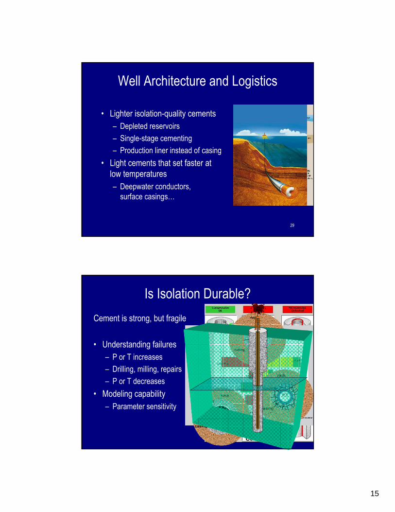
Well Architecture and Logistics
• Lighter isolation-quality cements
– Depleted reservoirs
– Single-stage cementing
– Production liner instead of casing
• Light cements that set faster at
low temperatures
– Deepwater conductors,
surface casings…
30
Cement A
Cement B
Is Isolation Durable?
Cement is strong, but fragile
• Understanding failures
– P or T increases
– Drilling, milling, repairs
– P or T decreases
• Modeling capability
– Parameter sensitivity
rock
cement
casing
P,T
rock
cement
casing
rock
cement
casing
P,T

16
31
Isolation Made Durable
• Controlled flexibility and expansion
– Isolation maintained
during P, T changes
– From construction to abandonment
32
A Tool in Well ArchitectureSummary

17
33
Cement in the Past
• A necessary evil?
• Commodity?
34
Cementing Today
0
0.2
0.4
0.6
0.8
1Early strength
Final strength
Permeability
Shrinkage
Bonding
Flexibility
Durability
Toughness
• Solutions portfolio
– Not only slurry
performance
– Set material properties
– Short/long-term well
requirements
• Modeling tools
– Fit-for-purpose,
cost-effective system

18
35
Cementing Tomorrow:
A Technology for the Future
• Oilwell cementing has evolved considerably
• Oilwell cementing will continue to quickly adapt
– New cements from cement manufacturers
– New tools from cementing service industry
• Physically active, chemically re-active or inert materials
• Process design/simulation means
– A true well engineering technology
• An interesting future
� Evolving cement industry
– Still considerable academic
research
– CO2 emissions
– Important engineering
development
� Oilfield cementing industry– More tools in the toolbox
• Materials, simulators
– Adapt to tomorrow’s well
requirements
– A true well engineering
technology
36
Thank you for your attention