cementless femoral hip system - medical ortovit ... necimentata sl-plus.pdf · capsular incision...
TRANSCRIPT

Surgical Technique *smith&nephewSL-PLUS™Cementless Femoral Hip System


SL-PLUS™ Standard and Lateral Stem
Table of Contents
Notes from the Author’s Clinic ............................................. 3Indications ........................................................................... 4Contraindications .................................................................. 5Preoperative Planning .......................................................... 5Surgical Technique ............................................................... 6Postoperative Treatment ..................................................... 13Explantation of the SL-PLUS Stem ........................................ 13Implants ............................................................................... 14Instrumentation .................................................................... 16Sterilization ......................................................................... 20
Nota Bene
The technique description herein is made available to the healthcare professional to illustrate the authors’ suggested treatment for the uncomplicated procedure. In the final analysis, the preferred treatment is that which addresses the needs of the patient.
1

2

Our non-cemented stem system, which comprises a double-cone straight stem with a rectangular cross section, was im planted for the first time in 1979. Continuous follow-up resulted in ongoing improvement, culminating in the de-velopment of the SL stem in 1993. This system was suitable for the vast majority of surgical indications and provided results that were much better than those obtained with the first implants.
The SL-PLUS™ lateral shaft was added to the SL range in 2002 in order to offer additional anatomical variants which are more difficult to treat with the standard shafts in terms of optimal reconstruction of the offset.
The latest SL-PLUS straight stem that is now available inte-grates the proven design features of the stem large-area anchor age in the bone. However, changes have been made in the proximal section to improve intraoperative manipulation of the implant and to increase primary stability even further by improving proximal force transmission.
The extremely positive clinical results we obtained over many years, have further increased confidence in this stem design. Thanks to consistent integration of the knowledge gained in the meantime, the SL-PLUS system has become the «GOLD STANDARD™» in non-cemented hip arthroplasty.
Professor Dr. med. K. ZweymüllerVienna Orthopaedic Hospital – Gersthof
Notes from the Author’s Clinic
3

All forms of femurs can be treated with the SL-PLUS™ straight stem prosthesis, except those with extreme curvature, e.g. after angulation osteotomies. In these cases, a prior corrective osteotomy could be considered.
Advanced hip joint wear due to degenerative, post-traumatic, or rheumatoid arthritisFracture or avascular necrosis of the femoral headState after prior surgery, e.g. osteosynthesis, joint reconstruction, arthrodesis, hemi-arthro-plasty, or total hip replacement
Indications Lateral Stem
– Varus femur forms– Trumpet shape of the proximal femur (champagne flute)– Insufficient soft tissue balancing– State after prior surgery (e.g. displacement osteotomies, pelvic osteotomies)
In the case of coxa vara, the CCD angle is smaller than the normal angle of 126°. Implanting stem prosthesis with a CCD angle of 131° or more can result in a medialization and/or lengthening of the leg.
By implanting a lateralizing stem, the lever arms can be reconstructed in such a way that the strength of the pelvic-trochanter muscles is restored. At the same time, this achieves opti-mal soft-tissue-balancing. This minimizes the risk of insufficient gait and, in extreme cases, the danger of luxation.
The trumpet shape of the proximal end of the femur (sometimes described as a champagne flute) also poses a surgical-technical challenge to most standard stems, which cannot always be ideally solved. If the femoral isthmus is narrow, only a stem model with a relatively short neck cone can be selected. This femoral shape, however, is usually characterized by a long femoral neck with a large femoral head. Implanting a conventional stem with a relatively short neck cone therefore does not always make ideal reconstruction of the anatomical conditions possible. This results in a medialization of the femoral stem. By lengthening the neck area, the lateralizing SL-PLUS stem allows a reconstruction of the anatomical condi-tions. This means that it is no longer necessary to contract the pelvictrochanter muscles by implanting a stem prosthesis that extends beyond the trochanter region proximally or has an excessively long neck length and leads to a lengthening of the leg.
Indications
4
• • •

5
• Acute or chronic infections, local or systemic• Severe muscle, nerve, or vascular diseases that endanger the respective limb• Lack of bone substance or defective bone quality that endangers the stable seating of
the prosthesis• Any concomitant disease that may endanger the implant function• Revision with extensive bone defects
Contraindications
Planning the correct prosthesis size is carried out preoperatively using the X-ray template. This requires an A/P X-ray and an axial X-ray. Preoperative planning should always be carried out for orientation purposes. X-ray templates of the SL-PLUS™ Standard and Lateral stem are available in a magnification of 15%.
Preoperative Planning
To determine the appropriate entrypoint for access of instruments to the medullary canal, it is recommended that the surgeon draw the femoral shaft axis on the AP radiograph and extend it proximally. This line indicates how far laterally it is neces-sary to place the box chisel to open up the canal. This entry point is easy to locate during surgery.
After the preoperative planning, the distance from the SL-PLUS stem to the greater and lesser trochanter can be measured for the purpose of intraoperative monitoring.
For the implantation of an SL-PLUS stem, both the SL/SLR-PLUS™ Basic Set as well as the corresponding SL-PLUS trial broach instrumentation are required.
X-Ray templates of SL-PLUS Standard and Lateral stems.
x

Note
Approach: anterolateral with patient lying in the supine position.
Users of other (minimally invasive) approaches are requested to also consult the following operative instructions: posterolateral approach (Lit. no. 1426); anterior approach (Lit. no. 1494).
Surgical Technique
Skin incision
• A longitudinal incision along the anterior edge of the greater trochanter, extending from O proximally to N distally to the tip of the trochanter (Line 1).
• An oblique incision extending from the an-terior edge of the greater trochanter towards the anterior superior iliac spine (Line 2).
• A reverse oblique incision approximating the intertrochanteric line (Line 3).
The fascial incision extends from the upper edge of the tip of the trochanter towards the anterior superior iliac spine.
Dorsal incision of the iliotibial band is option-ally possible.
Capsular incision and dissection
After blunt lateral entry between the tensor fasciae latae and gluteus medius/minimus, the raspatory is used to dissect along the femoral neck.
Sharp lateral retractors and a blunt medial Hohmann retractor are used during the surgical exposure. The arc of the rectus tendon is visualized, underpinned, incised, and released from its capsule.
6
The femoral neck is exposed via an H-shaped incision of the joint capsule, consisting of:
A longitudinal incision, placed as far medially as possible, and extending from the acetabular margin to the intertrochanteric line and a proximal transverse incision of the acetabular labrum, extending around the acetabular margin from approximately the nine o’clock to the three o’clock position and a distal transverse incision distal extending along the intertrochanteric line.
•
•
•
7
Hautschnitt
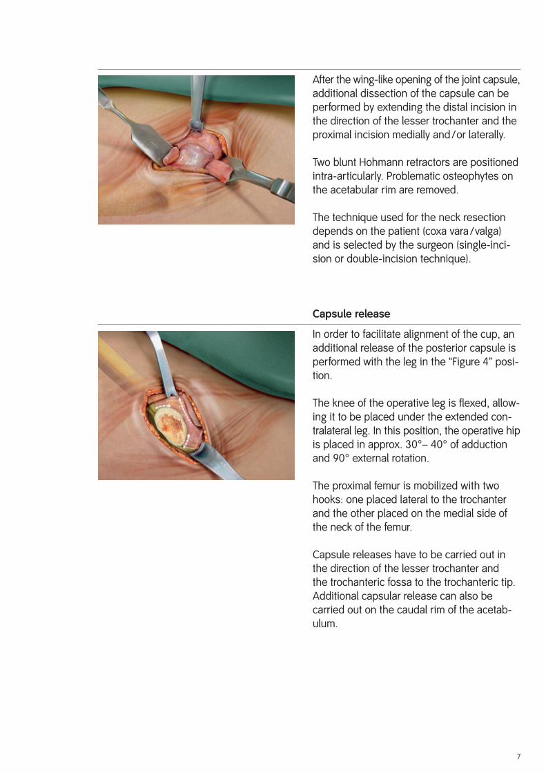
After the wing-like opening of the joint capsule, additional dissection of the capsule can be performed by extending the distal incision in the direction of the lesser trochanter and the proximal incision medially and/or laterally.
Two blunt Hohmann retractors are positioned intra-articularly. Problematic osteophytes on the acetabular rim are removed.
The technique used for the neck resection depends on the patient (coxa vara/valga) and is selected by the surgeon (single-inci-sion or double-incision technique).
Capsule release
In order to facilitate alignment of the cup, an additional release of the posterior capsule is performed with the leg in the “Figure 4” posi-tion.
The knee of the operative leg is flexed, allow-ing it to be placed under the extended con-tralateral leg. In this position, the operative hip is placed in approx. 30°– 40° of adduction and 90° external rotation.
The proximal femur is mobilized with two hooks: one placed lateral to the trochanter and the other placed on the medial side of the neck of the femur.
Capsule releases have to be carried out in the direction of the lesser trochanter and the trochanteric fossa to the trochanteric tip. Additional capsular release can also be carried out on the caudal rim of the aceta b-ulum.

Shaft preparation
The leg is hyperextended and adducted ap-prox. 30°– 40°, and placed in 90° of external rotation, with the operative leg positioned under the opposite leg, in the “Figure 4” po-sition.
In very muscular or obese patients, patients with a valgus femoral neck, or in cases where the proximal femur sits deep to the skin sur-face, further release of the posterior capsule or release of the piriformis tendon may be necessary to allow adequate mobilization of the femur prior to preparation of the implan-tation site.
Entry into the medullary cavity
With the lower thigh kept in a horizontal po-sition, the box chisel is placed close to the posterior cortex at the resection level. The box chisel should be introduced along the femo-ral axis and a small square block of bone is removed. If the box chisel is not used to clear hard bone from the osteotomy site, fracture of the trochanter may occur during rasp in-sertion.
Driving the box chisel below the level of the resected bony surface should also be avoid-ed.
The curved rasp facilitates opening of the diaphyseal IM canal.
Further opening of the diaphyseal medullary cavity and probing of the diaphysis with corresponding awl is recommended.
8
M. gemellus inteferior
M. obsturtortus internus
M. gemellus superior
M. piriformis

Hautschnitt
To prepare the bone bed to size 4, start with the rasp size 01. From size 5 onwards, prepa-ration can be started with rasp size 1. Connect the rasp with the offset adapter, which is avail-able in a variety of different designs.
9
The first rasp determines the position of all the following rasps. This is why its orientation is important for an exact positioning of the stem.
Hautschnitt
Rasping is carried out using the slap hammer or the rasping machine. The weight of these instruments helps to ensure the longitudinal alignment of the rasp within the femur. It is important that a lateral force is continuously applied to the rasping machine to ensure that the rasp moves in line with the axis of the canal and does not seat in a varus position.
Attention should be paid to the anteversion and varus/valgus alignment of the rasping machine with respect to the femoral axis. Insertion of the rasps or the stem in a varus inclination increases the risk of perforation and fracture of the lateral cortex of the femur.
At the start of the rasping process, the rasp must not be inserted below the level of the estimated final position of the implant. It is extremely important to understand that the femoral osteotomy has no relationship to the final position. There is a tendency for sur-geons to implant the starting smaller size rasps too deeply into the femur. This will re-sult in an excessive enlargement of the implantation site and lead to gaps around the medial aspect of the final implant posi-tion.
Bone loss in calcar arch

10
Hautschnitt
The broach the next size up is introduced into the cavity until the broach makes contact with the bone. The broach is then driven into the femur with lateral and distal pressure using the slap hammer or the rasping machine. Then go to the next larger broach in sequence until the appropriate size is reached.
The shoulder of the rasp corresponds to the height of the implant measured at the shoul-der of the prosthesis and should correspond to the preoperatively determined distance to the greater trochanter (marked X).
The aim is to achieve a long cortical batch with a large surface area. As the IM canal is expanded in increments the contact of the cortex increases and thus also the resistance when rasping. The rasp starts to broach the edges of the shaft, i.e. the rectangular shape from the cortex. As soon as the rasp is fully working on the cortex the pitch is higher and there are signs of the yellow cortex on the edge of the rasp. The ultimate check to ensure that the size is correct is preoperative planning with the X-ray image.
In rare situations, the prosthesis size determined intraoperatively is in disagreement with the size derived from preoperative templating. If this difference is two sizes or more, the rasp may not have reached the necessary depth because of incorrect angulation or the presence of an obstacle within the canal. In such cases, the implanted prosthesis is too small to provide stable long-term fixation. In these situations, intraoperative fluoroscopy or an intra-operative radiograph should be obtained to evaluate the obstruction.
x

Hautschnitt
The offset adapter is removed from the detachable rasp.
Trial reposition
The neck module is manually set onto the broach.
The trial ball head can be attached to the mo-dular neck in advance or in situ.
In each case, there is a standard modular neck for the detachable rasps of sizes 01–0, 1–6 and 7–12. The “lateral” modular necks are available to suit the detachable rasps of sizes 1–6 and 7–12.
Care should be taken that the modular neck is correctly seated on matching surface of the detachable rasp and engages properly.
11
The joint is repositioned and leg length, soft-tissue tension, and range of motion are checked.
If necessary the trial ball-head and/or the modular neck (standard or lateral) are changed until the results are satisfactory.
The modular neck can either be removed from the rasp manually or with a bone clamp.
The offset adapter is connected to the detachable rasp. The detachable rasp is removed from the canal using the slap hammer or the rasping machine.

Implantation of the stem
The correct size SL-PLUS™ stem is introduced manually as deep as possible into the canal, and is then seated with the impactor, using appropriately measured strokes to minimize the risk of fracture of the femur.
Pressing the stem in solely by hand is inadequate.
During impact, the protective cover remains positioned on the cone.
Once the stem is firmly seated, attempts to drive it further down the canal or to adjust its alignment within the femur cannot be per-formed without fracturing the bone.
Before repositioning the original ball-head the tapered trunnion conus is carefully cleaned by hand.
The ball head is then attached to the trunnion with a slight turning motion and permanently fixed with a blow delivered with the plastic hammer.
12

Hautschnitt
Metal objects must never be used to deliver impact to prosthetic heads. If a metal hammer is used, a plastic coupling or the head impactor must be used to protect the head from direct contact with the hammer.
Pressing the prosthetic head onto the trunnion solely by hand provides inadequate fixation.
Each femoral stem has a standard 12/14 trun-nion to allow coupling with ceramic or metal heads supplied by Smith&Nephew Orthopaedics.
13
Postoperative rehabilitation should be completed in accordance with each hospital’s own practies. The SL-PLUS™ stem is immediately load bearing. The definitive osseo-integration occur until three months postoperatively capable of bearing weight.
Postoperative Treatment
The SL-PLUS stem can be removed using the extraction screw M8 (Art. No. 110911).
If this causes difficulties, the extraction block can be used.
Important
It is important to insert the extraction screw axially.
Explantation of the SL-PLUS Stem

L
Art. No. Art. No. Plus Orthopedics Smith & Nephew Size Length (L)11420S 75002717 01 128 mm11421S 75002719 0 132 mm11401S 75002695 1 136 mm11402S 75002697 2 140 mm11403S 75002699 3 145 mm11404S 75002701 4 150 mm11405S 75002703 5 154 mm11406S 75002705 6 158 mm11407S 75002707 7 163 mm11408S 75002709 8 168 mm11409S 75002711 9 173 mm11410S 75002713 10 178 mm11411S 75002714 11 183 mm11412S 75002715 12 188 mm
All sizes also available with Integration-PLUS™ Ti-Plasmahydroxyapatite coating:
Art. No. Art. No. Plus Orthopedics Smith & Nephew Size Length (L)11459 75002720 01 128 mm11460 75002722 0 132 mm11461 75002723 1 136 mm11462 75002724 2 140 mm11463 75002725 3 145 mm11464 75002726 4 150 mm11465 75002727 5 154 mm11466 75002728 6 158 mm11467 75002729 7 163 mm11468 75002730 8 168 mm11469 75002731 9 173 mm11470 75002732 10 178 mm11471 75002733 11 183 mm11472 75002734 12 188 mm
Standard Implants
14
L

L
L
15
Art. No. Art. No. Plus Orthopedics Smith & Nephew Size Length (L)11531S 75002748 1 136 mm11532S 75002750 2 140 mm11533S 75002752 3 145 mm11534S 75002756 4 150 mm11535S 75002758 5 154 mm11536S 75002760 6 158 mm11537S 75002762 7 163 mm11538S 75002764 8 168 mm11539S 75002766 9 173 mm11540S 75002768 10 178 mm11541S 75002769 11 183 mm11542S 75002770 12 188 mm
All sizes also available with Integration-PLUS™ Ti-Plasma hydroxyapatite coating: Art. No. Art. No. Plus Orthopedics Smith & Nephew Size Length (L)11569 75002773 1 136 mm11570 75002777 2 140 mm11571 75002778 3 145 mm11572 75002779 4 150 mm11573 75002780 5 154 mm11574 75002781 6 158 mm11575 75002782 7 163 mm11576 75002783 8 168 mm11577 75002784 9 173 mm11578 75002785 10 178 mm11579 75002786 11 183 mm11580 75002787 12 188 mm
Lateral Implants

SL/SLR-PLUS™ Basic Instrumentation Set No. 0942000
Art. No. Description 110450 Case Basic Instruments 1/4� 990019 Easy Tray Lid Plastic� 110901 Slap Hammer 110902 Extractor Block 110903 Impactor 110904 Box Chisel 110911 Extraction Screw M8 110242 Head Impactor 160022 Trial Ball-Heads 22 M 160023 Trial Ball-Heads 22 L 160001 Trial Ball-Heads 28 S 160002 Trial Ball-Heads 28 M 160003 Trial Ball-Heads 28 L 160004 Trial Ball-Heads 28 XL 160005 Trial Ball-Heads 28 XXL 160011 Trial Ball-Heads 32 S 160012 Trial Ball-Heads 32 M 160013 Trial Ball-Heads 32 L 160014 Trial Ball-Heads 32 XL 160015 Trial Ball-Heads 32 XXL 160016 Trial Ball-Heads 36 S 160017 Trial Ball-Heads 36 M 160018 Trial Ball-Heads 36 L 160019 Trial Ball-Heads 36 XL
Optional:
21000138 Curved Rasp
Instrumentation
16

17

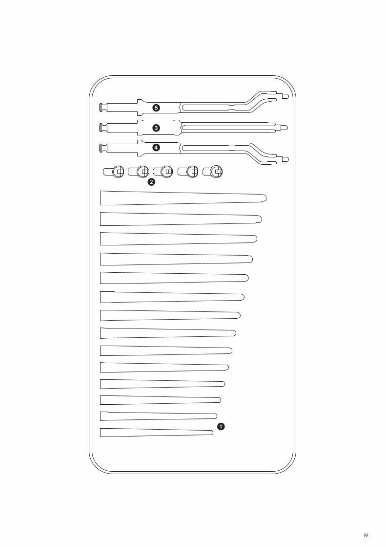
SL-PLUS™ Trial Broach with Adapter 25 mmSet No. 0943001
Art. No. Description 600930 Instrument Case 990019 Easy Tray Lid Plastic� 600899 Trial Broach 01 600900 Trial Broach 0 600901 Trial Broach 1 600902 Trial Broach 2 600903 Trial Broach 3 600904 Trial Broach 4 600905 Trial Broach 5 600906 Trial Broach 6 600907 Trial Broach 7 600908 Trial Broach 8 600909 Trial Broach 9 600910 Trial Broach 10 600911 Trial Broach 11 600912 Trial Broach 12� 21000253 Trial Neck Std 01–0 21000254 Trial Neck Std 1–6 21000255 Trial Neck Std 7–12 21000256 Trial Neck Std 1–6 21000257 Trial Neck Std 7–12� 600920 Broach Handle 25 mm� 600923 Broach Handle Left 17/13 mm� 600924 Broach Handle Right 17/13 mm
Optional:
600921 Adapter 40 mm (Set No. 0943005) 600922 Adapter 10 mm (Set No. 0943000)
18
19
�
�
�
�
�

Implants
All the implants described in this Surgical Technique are sterile when they are delivered by the manufacturer. Resterilization is not allowed.
Instruments
System components and instruments are not sterile when they are delivered. Before use, they must be cleaned by the usual methods in accordance with internal hospital regulations and sterilized in an autoclave in accordance with the legal regulations and guidelines ap-plicable in the relevant country. (For detailed information please refer to leaflet Lit. No. 1363.)
The correct settings are given in the instructions for use issued by the autoclave manu-facturer. Instrument manufacturers and dealers accept no responsibility for sterilization of products by the customer.
Sterilization
20


ManufacturerSmith & Nephew Orthopaedics AG For further information please contactErlenstrasse 4a our local sales office.6343 Rotkreuz www.smith-nephew.com Switzerland
™Trademark of Smith & Nephew. Lit. Nr. 1741-e Ed. 10/07 300 Ex. 11/07 0 1 2 3