central electricity authority · central electricity authority system planning & project...
TRANSCRIPT


Central Electricity Authority System Planning & Project Appraisal Division
Sewa Bhawan, R.K. Puram, New Delhi – 110066 No. 52/6/SP&PA-2015/ 1234-56 Date: 28-May-2015 Sub: Joint Meeting of the Standing Committee on Power System Planning of
Southern Region and Western Region - Minutes of the meeting
Sir,
The Joint Meeting of the Standing Committee on Power System Planning of
Southern Region and Western Region was held on 20 April, 2015 in NRPC
Committee room, Katwaria Sarai, New Delhi.
The Minutes of the meeting are enclosed.
The Minutes are available at CEA’s website ( www.cea.nic.in ).
Yours faithfully,
(Pardeep Jindal) Director (SP&PA)
(Telephone: 011 26732325, Fax No. 011 26102045) To Constituents of SR and WR SCPSP 1. The Member Secretary,
Southern Regional Power Committee, 29, Race Course Cross Road, Bangalore 560 009.
FAX : 080-22259343
2. The Member Secretary, Western Regional Power Committee, MIDC Area, Marol, Andheri East, Mumbai
Fax 022 28370193

2
3. CEO, POSOCO, B-9, Qutub Institutional Area, Katwaria Sarai, New Delhi-110016
4. COO (CTU, Planning), Power Grid Corp. of India Ltd. “Saudamini”, Plot No.2, Sector-29, Gurgaon 122 001, Haryana.
FAX : 95124-2571932
5.The Director (Transmission), Transmission Corp. of Andhra Pradesh
Ltd., (APTRANSCO) Vidyut Soudha, Hyderabad – 500 082. FAX : 040-66665137
6. The Director ( Grid Transmission and Management), Transmission Corp. of Telangana Ltd., (TSTRANSCO) Vidyut Soudha, Khairatabad Hyderabad – 500 082. FAX : 040-23321751
7 The Director (Transmission), Karnataka State Power Trans. Corp.Ltd.,
Cauvery Bhawan, Bangalore - 560 009. FAX : 080 -22228367
8. The Director (Trans. & System Op.), Kerala State Electricity Board, Vidyuthi Bhawanam, Pattom, Thiruvananthapuram - 695 004.
FAX : 0471-2444738
9. Member (Distribution), Tamil Nadu electricity Board (TNEB), 6th Floor, Eastern Wing, 800 Anna
Salai, Chennai - 600002. FAX : 044-28516362
10. The Superintending Engineer –I, First Floor, Electricity Department, Gingy Salai,
Puducherry – 605 001. FAX : 0413-2334277/2331556
11. Director (Operation),
MAHATRANSCO, 'Prakashgad', Plot No.G-9, Bandra-East, Mumbai-400051Fax 022-26390383/26595258
12. The Chief Engineer, Electricity Department,
The Government of Goa, Panaji Fax 0832 2222354
13. Chairman and Managing Director, MPPTCL, Shakti Bhawan, Rampur, Jabalpur-482008 Fax 0761 2664141
14. Executive Engineer (Projects) UT of Dadra & Nagar Haveli, Department of Electricity , Silvassa Ph. 0260-2642338/2230771
15. The Managing Director, CSPTCL, Dangania, Raipur (CG)-492013 Fax 0771 2574246/ 4066566
16. Executive Engineer Administration of Daman & Diu (U.T.) Department of Electricity Moti Daman-396220 Ph. 0260-2250889, 2254745
17. The Managing Director, GETCO, Sardar Patel Vidyut Bhawan, Race Course, Baroda-390007 Fax 0265-2338164

3
18. The Director (Power),
Corporate Office, Block – I, Neyveli Lignite Corp. Ltd., Neyveli , Tamil Nadu – 607 801.
FAX : 04142-252650
19. Director (Projects), National Thermal Power Corp. Ltd. NTPC Bhawan, Core-7, Scope
Complex, Lodhi Road, New Delhi-110003.
FAX-011-24360912 20. Director (Operations),
NPCIL, 12th Floor, Vikram Sarabhai Bhawan, Anushakti Nagar, Mumbai – 400 094. FAX : 022- 25991258
Copy to: 1. The Director (Projects),
Power Grid Corp. of India Ltd. “Saudamini”, Plot No.2, Sector-29, Gurgaon 122 001, Haryana. FAX : 95124-2571932
2. GM, SRLDC, 29, Race Course Cross Road, Bangalore 560 009 FAX – 080-22268725
3. GM, WRLDC Plot no F-3, MIDC Area, Msarol, Andheri(East) Mumbai-400093 Fax no 022-28235434

4
MINUTES OF MEETING
Minutes for Joint Meeting of Standing Committee on Power System Planning in Southern Region and Western Region held on 20 April, 2015 at NRPC, Katwaria Saria, New Delhi
1. Introduction 1.1 Member(PS), CEA informed the participants that a ± 800 kV Raigarh (HVDC
Stn, 6000 MW) – Pugalur (HVDC Stn,4000 MW) - Kerala (HVDC Stn,2000
MW) scheme was agreed in 37th meeting of SCPSPSR held on 31st July, 2014.
He said that MoP has allocated this scheme to PGCIL for implementation
under compressed time schedule. PGCIL vide their letter dated 13.01.2015
has proposed to modify the scope of the scheme. Since the issue involves
both WR and SR, therefore a joint meeting of both the regions has been called.
1.2 CE(SP&PA) welcomed the participants and requested Director (SP&PA) to
take up agenda item.
List of participants is given at Annex-I. 2.0 Modification proposed by PGCIL in Raigarh-Pugalur- Kerala 6000 MW
HVDC System 2.1 Director (SP&PA), CEA informed that PGCIL vide their letter dated 13.01.2015
has proposed to modify the scope for the scheme “HVDC Bipole link between
Western region (Raigarh, Chhattisgarh) and Southern region (Pugalur, Tamil
Nadu)-Madakathara/ North Trichur (Kerala)”, as given below:
(i) ± 800 kV Raigarh*(HVDC Stn) – Pugalur* (HVDC Stn) HVDC Bipole link
with 6000 MW capacity and 6000 MW of HVDC terminal at Raigarh
and Pugalur.
(ii) Establishment of VSC based 2000 MW HVDC link between Pugalur and
North Trichur* (Kerala) with 2000 MW VSC based HVDC terminal at
Pugalur and North Trichur each (The transmission link between Pugalur
and Kerala shall be through HVDC OH lines going into Kerala territory
and the portion of the link where ROW issues are anticipated shall be
established through UG cable upto Trichur terminal).

5
(iii) LILO of North-Trichur – Cochin 400 kV (Quad) D/c line at North Trichur
HVDC Stn.
(iv) Pugalur HVDC Station – Pugalur (Existing) 400kV (quad) D/c line.
(v) Pugalur HVDC Station – Arasur 400kV (quad) D/c line with 80 MVAR
switchable line reactor at Arasur end.
(vi) Pugalur HVDC Station – Thiruvalam 400kV (quad) D/c line with 80
MVAR switchable line reactor at both ends.
(vii) Pugalur HVDC Station – Edayarpalayam 400kV (quad) D/c line with 63
MVAR switchable line reactor at Edayarpalayam end.
(viii) Edayarpalayam – Udumalpet 400kV (quad) D/c line.
(ix) Establishment of 400/220kV substation at Edayarpalayam with 2x500
MVA transformers and 2x125 MVAR bus reactors.
(Note: *400 kV AC switchyard at the HVDC terminals shall be with hybrid
system of AIS & GIS)
2.2 He said that this scope is different from the earlier scope as agreed in the 37th
meeting of the SCPSPSR, held on 31-July-2014. He elaborated the difference
as given below:
SCPSPSR MoP PGCIL’s New Proposal (i) Raigarh(HVDC Stn) – Pugalur (HVDC Stn) +800kV 6000 MW HVDC bipole.
(i) ± 800 kV Raigarh (HVDC Stn) – Pugalur (HVDC Stn) – Madakkathara (HVDC Stn) HVDC Bipole line.
(i) ± 800 kV Raigarh (HVDC Stn) – Pugalur (HVDC Stn) HVDC Bipole link with 6000 MW capacity. And 6000 MW of HVDC terminal at Raigarh and Pugalur.
(ii) Establishment of Raigarh HVDC Stn +800kV with 6000 MW HVDC terminals
(ii) Establishment of Raigarh HVDC Stn with 6000 MW HVDC terminals
(iii) Establishment of Pugalur HVDC Stn with 6000 MW HVDC terminals or Alternatively: (a) Pugalur HVDC Stn with 4000 MW terminal, and
(iii) (a)Establishment of Pugalur HVDC Stn with 4000 MW HVDC terminalsl,

6
SCPSPSR MoP PGCIL’s New Proposal (b) Madakkathara, in Kerala HVDC Stn with 2000 MW terminal
and (b) Madakkathara, in Kerala HVDC Stn with 2000 MW terminal and inter-connection with existing 400kV AC S/S at Madakkathara.
(ii)Establishment of VSC based 2000 MW HVDC terminals at Pugalur and North Trichur (Kerala) each.
(Connectivity between Pugalur and Madakkathara/North Trichur as an extension of conventional HVDC line)
(Connectivity between Pugalur and Madakkathara/North Trichur as an extension of conventional HVDC line)
(iii)The transmission link between Pugalur and Kerala shall be through HVDC OH lines going into Kerala territory and the portion of the link where ROW issues are anticipated shall be established through UG cable upto Trichur terminal.
(iv) Inter-connection with existing 400kV AC S/S at Madakkathara
(iv) Inter-connection with existing 400kV AC S/S at Madakkathara
(iv)LILO of North-Trichur – Cochin 400 kV (Quad) D/c line at North Trichur HVDC Stn.
(AIS) (AIS) 400 kV AC switchyard at the HVDC terminals shall be with hybrid system of AIS & GIS
3.0 Issues for discussion, involved in the change of scope: 3.1 In regard to PGCIL’s new proposal, CEA had conveyed following observations
to PGCIL:
(i) The new proposal consists of additional + 320 kV, 2000 MW inverter/
Converter terminals at Pugalur and North Trichur.
(ii) The above is in addition to ±800 KV 6000 MW inverter/ Converter
terminals at Raigarh and Pugalur. Thus total 8000 MW terminal sets are
proposed instead of 6000 MW.
(iii) The additional 2000 MW capacity terminal-set would be VSC based
HVDC technology instead of conventional HVDC technology.
(iv) The reason of this modification in the scope, as given by PGCIL, is
uncertainty/ delay in obtaining 69m RoW for the ±800 kV HVDC line
between Pugalur and N Trichur. Therefore, the proposal also contains

7
constructing Pugalur- N Trichur link as cable or partly as combination
cable/ Over -head.
(v) The now suggested modifications would have additional cost impact,
primarily, due to following aspects:
a. Additional set of 2000 MW terminal
b. Use of VSC technology which is costlier then conventional HVDC
by about 1.3-1.7 times.
c. Cost of VSC HVDC cable between Pugalur and N Trichur
including cost required to purchase 5 m width of land throughout
the stretch.
(vi) The certainty/ uncertainty in procurement of 5 m wide land in the stretch
from North Trichur up to Kerala border to Pugalur, for cable laying also
need to be deliberated.
(vii) Barring cost implications, the use of VSC technology for overhead
transmission line is yet to be established/ matured and at present there
are only one or two such overhead lines in the world.
(viii) Can the additional cost be utilized in setting up an ISTS generation plant
in Kerala, which would be in addition to the agreed 2000 MW HVDC
terminal in Kerala.
3.2 Considering above observations, PGCIL was requested to prepare a detail
note covering following aspects. Accordingly, PGCIL has furnished a note on
above observation vide their letter dated 15.03.2015 which is given at Annex-II for reference:
a. Alternative feasible configurations of Converter stations.
b. The issues in RoW ( 69 m for +800 kV HVDC) in Pugalur – N.Trichur
part of the HVDC line in Kerala / Tamil Nadu portions, if any.
c. The issues in RoW for the Raigarh- Pugalur portion of the HVDC line,
in Chhatisgarh / Maharashtra / Telangana / Andhra Pradesh / Karnataka
/ Tamilnadu, if any.
d. Possibility of using RoW of the existing 220kV line from N. Trichur to
Palaghat for the Pugalur - N. Trichur HVDC link. PGCIL may explore if it
is possible to extend the existing RoW of this line of KSEB.

8
e. Cost of DC cable (in Rs./km-route-length for the HVDC line) including cost of land procurement ( about 5m width for about 100km
long stretch) for cable trenches in Kerala. (As these elements are first
time in India, PGCIL may furnish basis of cost estimates including
quotation from possible vendors.)
f. As this is a new technology, which are the possible vendors who can
supply DC cable for 2000 MW +/- 320kV VSC based system.
g. Comparative cost of converter terminals for VSC based v/s
conventional HVDC technologies. (As these elements are first time in
India, PGCIL may furnish basis of cost estimates including quotation
from possible vendors.)
h. As this is a new technology, which are the possible vendors who can
supply terminal equipments for a 2000 MW +/- 320kV VSC based
system.
i. Comparative cost of two options considering capital cost(completed cost) of the scheme and including transmission loss capitalization in two alternatives. It is understood that the VSC
based terminals have higher transmission losses as compared to
conventional technology.
j. The amount of power (in MUs per annum)that is likely to be transmitted through this HVDC link.
k. The number of Transition stations required and their cost.
l. Extra benefit/ Advantage/disadvantages/technological concerns of VSC
technology and technical issues like DC fault for VSC based over-head
lines.
m. Any issues if implemented in two stages/ or single contract but with
staggered delivery.
n. System Studies for inter connection of North Trichur HVDC Station
with 400kV system in Kerala. Indicative transmission system
strengthening required in Kerala state network, so that 2000 MW gets
absorbed in the Kerala without overloading/congestion of the 220kV or
110kV network in Kerala. It is requested that corresponding loadflow
and SLD file may also be sent to CEA.

9
o. Fault levels at Pugalur HVDC station under various operating conditions
for 2018-19 scenario for 16000 MW import in SR, i.e. with 6000 MW,
4000 MW, 2000 MW and 0 MW flow through this HVDC link. It is
requested that corresponding loadflow /short-circuit file may also be
sent to CEA.
4.0 Further deliberations in the meeting: 4.1 COO (CTU), PGCIL explained that out of the two possible alternatives. (i) Alt-I :
providing parallel bipoles and operating as a multi terminal, 6000MW at
Raigarh, 4000MW at Pugalur and 2000MW at North Trichur at +800kV level
and (ii) Alt-II: +800kV 6000MW HVDC LCC from Raigarh to Pugalur and
+320kV 2000MW(2x1000MW) VSC HVDC from Pugalur to North Trichur.
Alternative-II is being considered because of Right of way constraint. VSC
technology is more suitable in case of ROW problems as cables can be used
more easily and for +800kV cable is not available. Also, with the VSC based
terminals reactive support can be provided. This would improve the grid
stability.
PGCIL informed that as per the survey carried out by them about 32 km of
cable length in Kerala portion may be needed for Pugalur- Trichur link. They
indicated that the total cost of the complete scheme from Raigarh up to Trichur
would be about Rs. 20,000 crores. The presentation made by PGCIL in this
regard is given at Annex-IV.
4.2 Member Secretary, WRPC said that the requirement of additional 2000 MW
VSC based HVDC from Pugalur to Kerala is due to apparent RoW issues in
Kerala. Director, CEA said that the possibility of using RoW of existing
Palaghat – Trichur may be explored.
4.3 Kerala said that Row issue is expected between Palaghat and N. Trichur and if
the line got stuck due to it, then the Raigarh- Pugalur link would remain under
utilized. So, it is advisable to use the under ground cable instead of overhead
line. He also said that for +320 kV HVDC line about 35 m of RoW is needed
which is similar to RoW for a 220kV D/C line. At some stretches of the
proposed VSC HVDC overhead line the RoW of existing 220kV lines may be
used. However, use of RoW of 220kV line for + 800 kV HVDC which requires
69 m RoW may not be practically possible. He also said that the +800k V

10
Terminal would require more space near N Trichur 400kV S/S and finding such
space is difficult but for about + 320kV HVDC terminal land requirement is
about 30 acres only and can be made available.
4.4 Director (Projects), TANTRANSCO enquired about the possibility of building
Pugaular- N. Trichur line as 400kV AC lines, instead of HVDC. COO (CTU),
PGCIL replied that both Mysore- Kozhikode and Edamon- Cochin lines are
stuck up because of severe RoW problem in Kerala. Therefore only possibility
of the power supply to Kerala is through underground DC link wherever
overhead line is not practically possible.
4.5 MS, SRPC emphasized the need for VSC based HVDC terminal at Pugalur
and North Trichur each.
4.6 SE, MPPTCL (Madhya Pradesh) supported the new technology citing RoW as
the main reason in Kerala, however, he raised his concern for the increased
cost. PGCIL said that the cost of the complete scheme from Raigarh up to
Trichur would be about 20,000 crores. Estimated cost of the projects, as
provided by PGCIL, is given under Annexure-II of the Annex-II. MPPTCL said
that the cost of such links should be borne by the beneficiary states and should
not be a burden on other states.
4.7 SE, CSPTCL (Chhatisgarh) suggested to set up a new thermal power plant in
Kerala, to cater to future load growth instead of such high investment in
transmission system. There are number of land acquisition issues for setting
up new pithead based generation capacity in coal rich states and RoW issues
are also being faced for laying transmission lines required for evacuation of
power from such pithead based generating stations. CEA stated that in the last
five years no capacity has been added in Kerala and neither much is in
construction where else the load of Kerala is going to increase by about 2000-
3000 MW in next 5 years. So, practically, Kerala will have to import all its need
from outside if they don’t add generation capacity in their state. Director
(Transmission), KSEBL informed that they are planning a thermal power plant
in Kasargode but it will take some time to materialize.
4.8 Director (CEA), suggested that the whole system can be planned as 3 separate
schemes., HVDC part, AC part and VSC part of the scheme can be treated as
three schemes separately so that the work on all three of them can be started
at the same time.

11
4.9 Director (WR), CEA asked whether Raigarh HVDC Station – Raigarh(Existing)
400kV (quad) 2xD/c lines would be sufficient for 6000 MW injection at Raigarh
HVDC station.
4.10 CTU stated that there is a change in the scheme and now the Raigarh HVDC
terminal would be adjacent to the existing AC substation only and would be an
extended bus.
4.11 Director (Trans), KPTCL said that it is a new technology and he raised the
issues of transport of such heavy cables on such stretches that have ROW
issues in Kerala. He also expressed guide lines for use of EHV cable in
transmission lines where there are RoW problems.
4.12 ED, PGCIL said that about 5 m width of land may have to be acquired through
out the length of cable route. This requirement would be reduced to 2 to 4 m if
the cable is laid along the highway. KSEB responded that they are exploring
the possibility of laying the cable along the NH 47.
4.13 AGM (System Operation), POSOCO said that if we have to adopt a VSC
option from Pugalur to Kerala, we may consider a different take off point other
than Pugalur. This would give better flexibility and reliability in comparison to
Pugalur having 8000 MW (6000 MW LCC + 2000 MW VSC) terminal at one
place only. He also said that some of the presentations enclosed with the
agenda suggest that each cable is generally capable of 200-250 MW; so do we
need 8-10 cables for 2000 MW; does the 5 m ROW capture all this? CTU
subsequently clarified that single cable is available for 1000 MW.
POSOCO also expressed that HVDC-HVDC controller interactions could be a
concern due to close proximity of HVDC terminals, and required studies.
COO(CTU), PGCIL stated that for VSC systems, HVDC-HVDC controller
interactions may arise which would be analyzed at the time of detail designing.
POSOCO also said that the STATCOMs earlier planned at Trichy and
Udumulpeta may need to be reviewed in the light of VSC terminal at Pugalur
considering the dual advantages of VSC based HVDC systems. PGCIL
explained that the review of STATCOM would not be needed because the
natural STATCOM of VSC link will be for HVDC only.
POSOCO also stated that the behavior of HVDC system as well as the power
system stability needs to be studied in the planning horizon considering
eventuality such as delayed clearance of faults in the AC transmission system

12
in close proximity to HVDC terminals (Kolar, Pugalur, Champa etc),
disconnection of large wind farms in Tamilnadu in the absence of Fault Ride
Through (FRT) capability etc.
4.14 Director(SP&PA), CEA said that presently there is only one overhead link built
using VSC HVDC technology (which is presently under construction) having
capacity of the order of 1000 MW or more in the world. PGCIL said that in the
present technology, there is a minor issue on fault clearing time for overhead
VSC links. The link would be out for about 1- 2 second under transient fault,
after which it is restored.
4.15 Director(SP&PA), CEA said that additional 220 kV outlets which would be
commissioned by KSEBL for evacuation of 2000 MW must also be listed out,
otherwise as per system studies, only 610 MW, out of 2000 MW of power
could be transmitted. The preliminary studies in this regard were presented
which are enclosed at Annex-III. 4.16 CEA informed that Gujarat Electricity Transmission Co.(GETCO), vide their
email dated 16-04-2015 has conveyed their no objection to the proposed
system (copy enclosed at Annex-V). 4.17 The overload capacity of the HVDC system in case of contingency was also
discussed. Director(SP&PA), CEA stated that provision of an overload capacity
for contingency is only for short duration, and keeping an overload capacity on
continuous basis would tantamount to under-stating of the equipment ratings.
Therefore, after discussion it was agreed that this HVDC system would be
designed with normal overload ratings i.e. 20% overload for 30 minutes and
10% overload for 2 hours.
5.0 After further deliberation following systems were agreed: 5.1 Scheme # 1: Raigarh-Pugalur 6000 MW HVDC System
1. Establishment of Raigarh HVDC Station +800kV with 6000 MW HVDC
terminals. This Raigarh Station would be implemented with extended bus of
Raigarh(Kotra) existing 400kV S/S. The HVDC Station would have GIS for
400kV part and AIS for HVDC part.

13
2. Establishment of Pugalur HVDC Stn +800kV with 6000 MW HVDC
terminals. The HVDC Station would have GIS for 400kV part and AIS for
HVDC part.
3. ± 800 kV Raigarh (HVDC Stn) – Pugalur (HVDC Stn) HVDC Bipole link with
6000 MW capacity.
This system would be designed with normal 20% overload for 30 minutes and
10% overload for 2 hours, as discussed above. Estimated cost of this scheme is Rs. 13776 crore
5.2 Scheme # 2: AC System strengthening at Pugalur end
1. Pugalur HVDC Station – Pugalur (Existing) 400kV (quad) D/c line 2. Pugalur HVDC Station – Arasur 400kV (quad) D/c line.
3. Pugalur HVDC Station – Thiruvalam 400kV (quad) D/c line with 2x80
MVAR line reactor at Pugalur HVDC Station end and 2x63 MVAR line
reactor at Thiruvalam 400kV end.
3. Pugalur HVDC Station – Edayarpalayam 400kV (quad) D/c line with 63
MVAR switchable line reactor at Edayarpalayam end.
4. Edayarpalayam – Udumulpeta 400kV (quad) D/c line. (Establishment of 400/220kV substation at Edayarpalayam with 2x500
MVA transformers and 2x125 MVAR bus reactors would be under the
scope of TANTRANSCO. The bay for ISTS transmission lines at
Edayarpalayam would be implemented as ISTS.)
Estimated cost of this scheme is Rs. 2008 crore 5.3 Scheme # 3: Pugalur- Trichur 2000 MW VSC Based HVDC System
1. +320kV, 2000 MW VSC based HVDC terminal at Pugalur. The HVDC
Station would have GIS for 400kV part and AIS for HVDC part.
2. +320kV, 2000 MW VSC based HVDC terminal at North Trichur. The HVDC
Station would have GIS for 400kV part and AIS for HVDC part.
3. Establishment of VSC based 2000 MW HVDC link between Pugalur and
North Trichur* (Kerala).

14
(*part/parts of this link, in the Kerala portion, may be implemented as
underground cable where implementation as overhead transmission line is
difficult because of RoW issues).
4. LILO of North-Trichur – Cochin 400 kV (Quad) D/c line at North Trichur
HVDC Stn.
Estimated cost of this scheme is Rs. 3769 crore
5.4 Additional system strengthening to be identified by KSEBL, jointly with CEA
and CTU, for enabling Kerala to absorb up to 2000 MW of power received
through this 2000 MW HVDC link. This system strengthening would be
implemented by KSEBL as intrastate transmission system in Kerala.
5.5 The above schemes may be implemented as separate schemes however it is
important that the scheme no. 2 and Scheme no. 3 should be in place before
commissioning of 6000 MW Raigarh- Pugalur link.

15
Annex-I
List of participants for the Joint Standing Committee on Power System Planning in Southern Region and Western Region held on 20-04-2015 at NRPC Office, Katwaria Sarai, New Delhi Sl. No. Name and Organization Designation
Central Electricity Authority (CEA)
1. Major Singh Chairperson (I/c) and Member (PS) 2. K K Arya Chief Engineer(SP&PA) 3. Pardeep Jindal Director (SP&PA) 4. Awdesh K. Yadav Director (SP&PA) 5. Manjari Chaturvedi Deputy Director (SP&PA) 6. Shivani Sharma Deputy Director (SP&PA)
Southern Region Power Committee (SRPC)
1. S.R.Bhat Member Secretary 2. Anil Thomas EE
Western Region Power Committee(WRPC)
1. S. D. Taksande Member Secretary
Power Grid Corporation of India Ltd (PGCIL)
1. I. S.Jha Dir(Proj.) 2. Seema Gupta COO-CTU 3. R. K. Chauhan ED 4. Mukesh Khanna AGM(CTU Plg.) 5. B. B. Mukherjee DGM 6. V.Thayagrajan Asstt GM 7. Ankita Singh Sr. Engineer(CTU Plg.)
Power System Operation Corp. Ltd (POSOCO)
1. S. R. Narasimhan AGM(SytemOp) (NLDC) 2. N. Nallarasan DGM(NLDC) 3. Anbunesan. G AGM(SRLDC) 4. S.P. Kumar DGM(SRLDC)

16
Sl. No. Name and Organization Designation
5. Madhukar G Dy. Manager (SRLDC) 6. P. Mukhopadhyay GM(WRLDC) 7. Vivek Pandey CE (WRLDC) 8. Abhimanyu Gartia DGM(WRLDC)
Chhattisgarh State Power Transmission Co Ltd(CSPTCL)
1. D.K. Chanda SE Madhya Pradesh Power Trans. Corp. Ltd. (MPPTCL)
1. M.M. Dhoke SE 2. R.S. Shrivuli ACE
Kerala State Electricity Board Ltd(KSEBL)
1. K Venugopal Director(T&SO)
Tamil Nadu Electricity Board/TANGEDCO/ TANTRANSCO 1. R. Kaliselvan Dir/Trans. 2. S. Ramchadran SE
Karnataka Power Transmission Co Ltd(KPTCL)
1. Sumanth Dir (Trans.)

17
Annex II
Point Wise Reply to Clarifications sought by CEA
(a): Alternative feasible configurations of Converter stations.
Reply - There are two possible alternatives. (i) Alt-I : providing parallel bipoles and
operating as a multi terminal, 6000MW at Raigarh, 4000MW at Pugalur and 2000MW
at North Trichur at +800kV level and (ii) Alt-II: +800kV 6000MW HVDC LCC from
Raigarh to Pugalur and +320kV 2000MW(2x1000MW) VSC HVDC from Pugalur to
North Trichur.Here it may be mentioned that another alternative would be to consider
conventional LCC HVDC from Pugalur to North Trichur. However Alternative-II is
being considered because of Right of way constraint. VSC technology is more
suitable in case of ROW problems as cables can be used more easily.
(b): The issues in RoW( 69 m for +800 kV HVDC) in Pugalur – N.Trichur part of the
HVDC line in Kerala / Tamil Nadu portions, if any.
Reply- RoW problem is anticipated from Tamil Nadu -Kerala border to North Trichur
primarily due to high value plantations.
(c): The issues in RoW for the Raigarh- Pugalur portion of the HVDC line, in
Chhtisgarh / Maharashtra / Telangana / Andhra Pradesh / Karnatak/ Taminadu, if
any.
Reply- As of now, normalRoW issues are foreseen in this portion.
(d): Possibility of using RoW of the existing 220kV line from N.Trichur to Palaghat for
the Pugaur-N.Trichur HVDC link. PGCIL may explore if it is possible to extend the
existing RoW of this line of KSEB. Reply- The available RoW for 220kV line is 35 meters. The required RoW for
composite 800 kV DC + 220 kV AC multi-circuit line is 69 meters. Preliminary survey
has indicated that 50% of route is covered by rubber plantation. It may be difficult to
obtain the additional RoW. Further, new type of tower is required with a height of 90
meters with wider foot print (approx. 35 mX35 m) against the (20mX20 m) of standard
800kV DC Tower and 8mx8m of 220kV D/c tower.
(e): Cost of DC cable (in Rs./km-route-length for the HVDC line) including cost of land
procurement (about 5m width for about 100km long stretch) for cable trenches in

18
Kerala. (As these elements are first time in India, PGCIL may furnish basis of cost
estimates including quotation from possible vendors.)
Reply- Approx. cost is 90Million Euro for 64km Route length. taking 1 euro=70 INR,
cost work out to about INR 9.8 crore/km route length (source: public domain website
from INELFE VSC Project, cable supplier- M/s Prysmian). Actual cost shall be known
after tender/ Bidding.The cable route is yet to be finalized. There is a feasibility of
taking the cable along National highways(NH47). In this case, the land procurement
cost will be minimized.
(f): As this is a new technology, which are the possible vendors who can supply DC
cable for 2000 MW +/- 320kV VSC based system.
Reply- Cable Supplierswho can supply the cable are (i)Prysmian, ii) ABB, iii) Nexan.
The VSC technology using cable is well established and all renowned vendors have
supplied no. of VSC projects world wide (copy enclosed at Annexure-I). (g): Comparative cost of converter terminals for VSC based v/s conventional HVDC
technologies. (As these elements are first time in India, PGCIL may furnish basis of
cost estimates including quotation from possible vendors.) Reply- Comparative cost of proposed Alternative-I & II is enclosed at Annexure-II.Budgetary quotation of major vendors is also enclosed at Annexure-IIA.
(h): As this is a new technology, which are the possible vendors who can supply
terminal equipment for a 2000 MW +/- 320kV VSC based system.
Reply- The technology is very much proven and has been used worldwide as given
in the Annexure-I. ABB, Siemens, Alstom have implemented various VSC project as
indicated in the Annexure-I. (i) Comparative cost of two options considering capital cost(completed cost) of the
scheme and including transmission loss capitalization in two alternatives. It is
understood that the VSC based terminals have higher losses as compared to
conventional technology.
Reply- Terminal losses are generally of the order of 0.75 % of rated capacity at
each terminal in case of LCC HVDC and 1.0 % of rated capacity at each terminal in
case of VSC HVDC terminal. Line losses are current dependent. In case of Alt I Line
loss is lower than Alt II . The transmission loss capitalization cost shall be approx. 195

19
Cr for VSC link considering overhead line. Introduction of DC cable will further reduce
capitalization cost.
(j) The amount of power (in MUs per annum) that is likely to be transmitted through
this HVDC link
Reply- Transmission system is planned based on peak power requirement and never
based on energy. As indicated by KSEB during 37th SCM meeting, Kerala requires
an additional import capability of around 2000 MW by year 2018 and 4000 MW by
year 2022. The system requirement was discussed and a 2000MW HVDC to Pugalur
was agreed.
Regarding energy transfer through the HVDC, making a conservative estimate power
flow through the HVDC would be proportional to load,i.e the utilisation would be same
as the load factor. The load factor of Kerala is 55% as per 18th EPS. Hence energy
transfer works out to 9636MU (2000MW*365*24*55%). Here it may be mentioned that
for the year 2013-14 as per the EPS energy demand of Kerala is 18400MU while the
energy demand actually was 21577MU. As per EPS the energy demand would grow
by about 5.8%. Hence projecting present demand, the energy demand would grow by
more than 1500MU/ year beyond 2018-19. Hence the HVDC is expected to be
utilised gainfully as envisaged during planning and less than 10% change in cost is
not going to change the viability of the project.
(k)The number of Transition stations required and their cost.
Reply-Presently 01(one) no. envisaged. Cost per transition station is approx. 1 million
USD.
(l): Extra benefit/ Advantage/disadvantages/technological concerns of VSC
technology and technical issues like DC fault for VSC based over-head lines.
Reply- VSC offers significant merits in comparison of LCC scheme. Some of them
are as follows:
Independent active and reactive power support; Can be used as STATCOM Black start capability No commutation failure Use of conventional auto transformer in place of converter transformer Generally no or very little Harmonic filters requirements Less equipment Less space requirement due to less equipment
Some of the disadvantages are increased station losses (defined above in reply (i) ),
Slightly higher cost (10-15 % higher than that of LCC ) and DC OH line fault

20
performance i.e. Slightly Higher recovery time e. g 750 mSec (considering 3 restart )
for LCC and around 1000 msec for VSC.
(m): Any issues if implemented in two stages/ or single contract but with staggered
delivery.
Reply- Even if a project is Staggered at the time of the contract itself, the staging and
time period has to be indicated. If there is any uncertainty in time period of
materialisation, then the same would lead to loading in the early stages itself. Further
the project would have to be awarded to the same contractor itself to avoid
contractual, and interface issues.
(n):System Studies for inter connection of North Trichur HVDC Station with 400kV
system in Kerala. Indicative transmission system strengthening required in Kerala
state network, so that 2000 MW gets absorbed in the Kerala without
overloading/congestion of the 220kV or 110kV network in Kerala. It is requested that
corresponding load flow and SLD file may also be sent to CEA.
Reply- Studies has been carried out with 2000MW injection at North Trichur. Injection
is through LILO of Cochin-North Trichur 4000kV D/c (Quad line). The total load of
Kerala is about 5425MW which is met by self-generation of 1360MW and import of
4065MW. The details of tie line flows are shown in Exhibit-I. From the Exhibit-I it is
seen that Edamon-Tirunellveli is loaded to 363MW per circuit. Under one pole outage
the loading on the line increases to 376MW on each circuit. For above load-
generation balance in the absence of proposed HVDC bipole, loading on Edamon-
Tirunellveli is 390MW per circuit.
Load flow simulations are plotted in Exhibit-II & III. Under (n-1) condition, no
constraint is envisaged on line loadings around North Trichur. However, transformers
at Cochin and North Trichur gets loaded to 694MW (630MW) and 780MW (630MVA)
even under base case. Transformers augmentation as proposed during 37th SCM
needs to be taken up with matching 220kV augmentation. Under (n-1-1) contingency
if both North Trichur-North Trichur (HVDC) are taken under outage then the entire
power would flow towards Kochin and about 1285MW is dropped through
transformers and remaining power flows towards Trirunelvelli. Strengthening of 220kV
to be taken up at Kochin.

21
Fault levels at Pugalur HVDC station under various operating conditions for 2018-19 scenario for 16000 MW import in SR, i.e. with 6000 MW, 4000 MW, 2000 MW and 0 MW flow through this HVDC link. It is requested that corresponding load flow /short-circuit file may also be sent to CEA.
Reply – Fault level at Pugalur HVDC with various HVDC flow levels are enclosed at
Exhibit-IV. The results are tabulated below:
HVDC Power flow
Short Circuit level at Pugalur
1 0 MW 30.23 kA 2 2000MW 30.10 kA 3 4000MW 29.95 kA 4 6000MW 29.85 kA
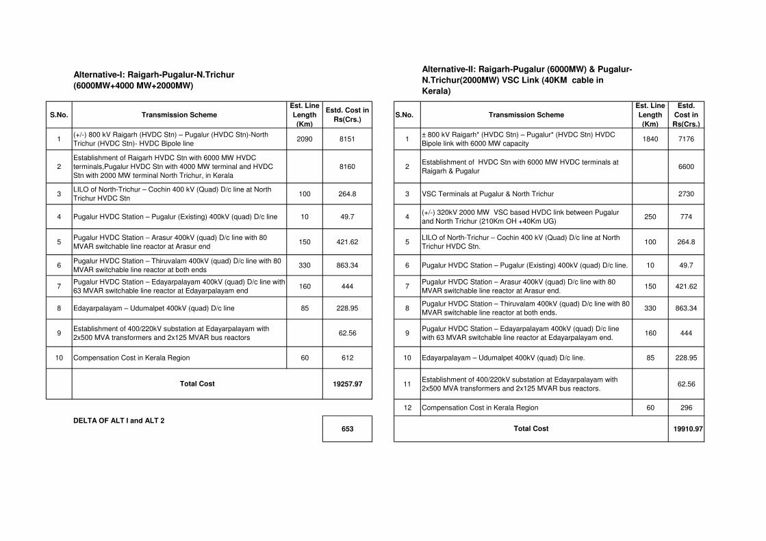
Alternative-I: Raigarh-Pugalur-N.Trichur
(6000MW+4000 MW+2000MW)
Alternative-II: Raigarh-Pugalur (6000MW) & Pugalur-
N.Trichur(2000MW) VSC Link (40KM cable in
Kerala)
S.No. Transmission Scheme
Est. Line
Length
(Km)
Estd. Cost in
Rs(Crs.)S.No. Transmission Scheme
Est. Line
Length
(Km)
Estd.
Cost in
Rs(Crs.)
1(+/-) 800 kV Raigarh (HVDC Stn) – Pugalur (HVDC Stn)-North
Trichur (HVDC Stn)- HVDC Bipole line2090 8151 1
± 800 kV Raigarh* (HVDC Stn) – Pugalur* (HVDC Stn) HVDC
Bipole link with 6000 MW capacity1840 7176
2
Establishment of Raigarh HVDC Stn with 6000 MW HVDC
terminals,Pugalur HVDC Stn with 4000 MW terminal and HVDC
Stn with 2000 MW terminal North Trichur, in Kerala
8160 2Establishment of HVDC Stn with 6000 MW HVDC terminals at
Raigarh & Pugalur6600
3LILO of North-Trichur – Cochin 400 kV (Quad) D/c line at North
Trichur HVDC Stn100 264.8 3 VSC Terminals at Pugalur & North Trichur 2730
4 Pugalur HVDC Station – Pugalur (Existing) 400kV (quad) D/c line 10 49.7 4(+/-) 320kV 2000 MW VSC based HVDC link between Pugalur
and North Trichur (210Km OH +40Km UG)250 774
5Pugalur HVDC Station – Arasur 400kV (quad) D/c line with 80
MVAR switchable line reactor at Arasur end150 421.62 5
LILO of North-Trichur – Cochin 400 kV (Quad) D/c line at North
Trichur HVDC Stn.100 264.8
6Pugalur HVDC Station – Thiruvalam 400kV (quad) D/c line with 80
MVAR switchable line reactor at both ends330 863.34 6 Pugalur HVDC Station – Pugalur (Existing) 400kV (quad) D/c line. 10 49.7
7Pugalur HVDC Station – Edayarpalayam 400kV (quad) D/c line with
63 MVAR switchable line reactor at Edayarpalayam end160 444 7
Pugalur HVDC Station – Arasur 400kV (quad) D/c line with 80
MVAR switchable line reactor at Arasur end. 150 421.62
8 Edayarpalayam – Udumalpet 400kV (quad) D/c line 85 228.95 8Pugalur HVDC Station – Thiruvalam 400kV (quad) D/c line with 80
MVAR switchable line reactor at both ends.330 863.34
9Establishment of 400/220kV substation at Edayarpalayam with
2x500 MVA transformers and 2x125 MVAR bus reactors62.56 9
Pugalur HVDC Station – Edayarpalayam 400kV (quad) D/c line
with 63 MVAR switchable line reactor at Edayarpalayam end. 160 444
10 Compensation Cost in Kerala Region 60 612 10 Edayarpalayam – Udumalpet 400kV (quad) D/c line. 85 228.95
19257.97 11Establishment of 400/220kV substation at Edayarpalayam with
2x500 MVA transformers and 2x125 MVAR bus reactors.62.56
12 Compensation Cost in Kerala Region 60 296
DELTA OF ALT I and ALT 2653 19910.97
Total Cost
Total Cost

Sl. No. Description
Million Euro
Equivalent M INR (1
Euro= 70 INR) Million USD
Equivalent M INR
(1 USD= 62INR) Million Euro
Equivalent M INR
(1 Euro= 70 INR)
1 ±320kV, 2000 MW VSC TERMINALS AT PUGALUR &
TRICHUR390.00 27,300.00 520.00 32,240.00 558.00 39,060.00
2Per MW cost - 1.365 CR/ MW 1.6CR/ MW 1.9 CR/ MW
SIEMENS ABB ALSTOM
BUDGETARY QUOTATION OF +/-320kV, 2000 MW VSC TERMINALS AT PUGALUR & TRICHUR

22
Annex- III
Sl.No Case Exhibit No.
1. Base Case Exhibit-1
2. Case-1: N-1-1 of North Trichur-NTrichur HVDC 400 kV (Quad) D/c line
Exhibit-2
3. N-1 of Palakkad-Udmulpet on Case-1 Exhibit-2a
4. Kerala load met with permissible loading onKochinT/f on Case-1(3850MW Kerala load) & (600MW power flow on HVDC)
Exhibit-2b
5. Case-2:HVDC to Kerala not considered and import through AC lines
Exhibit-3
6. N-1 of Palakkad-Udumalpet on Case-2 Exhibit-3a
7. Kerala load met with permissible loading under N-1 of Palakkad-Udumalpet (852MW)on Case-2(4670MW Kerala load)
Exhibit-3b
8. Case-3: only 1000MW on Pugalur-NTrichur HVDC Exhibit-4
In case-1 the 220kV network around Kochin area gets highly over loaded. For Exhibit-2b power flow on HVDC is restricted to 600 MW and load of Kerala to 3850MW to bring the transformer loading on Cochin within the limits (610MW).


Annex IVAnnex IVProposed Proposed Configuration for 6000MW Configuration for 6000MW
R i hR i h P lP l N thT i hN thT i hRaigarhRaigarh--PugalurPugalur--NorthTrichurNorthTrichurHVDC S tHVDC S tHVDC SystemHVDC System
2020thth April, 2015April, 2015
Proposed Scheme - As per 37th SCMAlt I- Delivery of bulk power of 6000 MW from Raigarh toPugalur (Conventional 800 KV HVDC Bipole ) orPugalur (Conventional 800 KV HVDC Bipole ) orAlt II- Delivery of 4000 MW at Pugalur and 2000 MW atNorth TrichurNorth-Trichur
MOP vide Letter Dt 10th Dec 2014 defined the scope as perMOP vide Letter Dt. 10th Dec, 2014 defined the scope as perALT II i.e. 4000 MW terminal at Pugalur and 2000 MWt i l t T i h i 800 KV HVDC M lti T i l Li kterminal at Trichur using 800 KV HVDC Multi Terminal Link
2

As per SCM & MOP(Alternative-I)Establishment of ± 800 kV, 4000 MW (2 x 2000 MW size)HVDC Bipole Terminal each at Raigarh in Chattisgarh andp g gPugalur (Tamil Nadu).
Establishment of ± 800 kV, 2000 MW (2x1000 MW size)Parallel Bipole (Multi-Terminal mode) at Raigarh inp ( ) gChattisgarh and new Bipole at North Trichur (Kerala) inMulti-Terminal modeMulti Terminal mode
± 800kV HVDC Line from Raigarh to North Trichur viaPugalur. Line length from Raigarh to Pugalur is 1840 Kmand Pugalur to Trichur is 250 Km
3
g
Estimated Cost= Rs 19257 Cr
Alternative-I

Issues in Alternative-IRight of Way (ROW) 69 m required for + 800 kV DC system
ROW problem is anticipated for establishment of + 800 kVROW problem is anticipated for establishment of + 800 kVDC transmission system between Pugalur and NorthT i hTrichur.
In case Pugalur-North Trichur section is stuck up due tog pROW issues like Edamon – Cochin (Stranded for last 7years)years)
Investment shall be blocked for indefinite period
2000 MW capacity of DC transmission line of 1840 kmwould remain unused
5
Present Proposal (Alternative-II)Establishment of ± 800 kV, 6000 MW HVDC Terminal (4x1500 MWsize) at Raigarh and Pugalur (consisting of two bipoles in parallel)with 1.33 pu continuous overload for each 1500 MW converter.)
+800kV HVDC line between Raigarh and Pugalur.Establishment of ± 320 kV, 2000 MW (2x 1000 MW size) VSC Terminal atPugalur & North Trichur.
The connection of Pugalur to N.Trichur by +320 kV HVDC line (apprx.route length 220 km, ROW equivalent to 400 kV D/C) and +320 kV HVDC
bl ( l h 33 k ROW 4 )cable (apprx. route length 33 km, ROW 4 m)
Estimated cost: INR 19742 Cr (approx.)
Difference in cost Between Alt-II and Alt-I = Rs 485 Cr.(Incremental cost is less than 5% as compared to Alternative-I)
6

Alternative-II
Salient Features-Alternative-IILesser footprint of the smaller towers used for the +320 kV DCline can address ROW problem
Lower cost of extruded XLPE cables (3cr/km) can be used withminimal ROW in the route closer to cities and dense habitationwhere it is difficult to obtain ROW for +320kV overhead line.
Dynamic voltage support at converter bus at both Pugalur andDynamic voltage support at converter bus at both Pugalur andNorth Trichur through dynamic compensation.
f ( 0% f CC f )Footprint for terminal is less (approx. 50% of LCC of same rating)
Both LCC (a) and VSC (c) terminals can be controlled separatelyBoth LCC (a) and VSC (c) terminals can be controlled separatelyand can independently offer flexibility.
8Procurement of land may be required along the cable route.

Salient Features-Alternative-IIFor DC line fault scenario between Raigarh –Pugalur Section(+ 800 kV DC line of LCC link), Pugalur –North Trichur section( ), gshall not be affected for DC power transmission from Pugalur toNorth Trichur, can address acute RoW issue effectively from, yPugalur to North Trichur and offer flexibility in construction,implementation and operationp e e tat o a d ope at o
Preliminary survey indicates possibility for use of NH 47 corridorfor 320 kV HVDC cable routing from Trichur Terminal for upto 33KMS.
9
Salient Features-Alternative-II
Interaction is minimised between two HVDC converters atP l (R+I) ith l ti f VSC HVDC d tPugalur (R+I) with selection of VSC HVDC as compared toLCC between Pugalur and Trichur.
Effects of variation of large renewable generation in TN aremitigated with VSC HVDC link.g
Full 6000 MW can be transmitted to Southern Region
VSC technology for HVDC and STATCOM is in commercialuse since 2000use since 2000
10

Manjari Chaturvedi <[email protected]>
Fwd: Agenda of the Standing Committees on Power System Planning of SRand WR
STU Cell GETCO <[email protected]> Thu, Apr 16, 2015 at 11:41 AMReply-To: STU Cell GETCO <[email protected]>To: "[email protected]" <[email protected]>, "[email protected]"<[email protected]>, "[email protected]" <[email protected]>, "[email protected]"<[email protected]>, "[email protected]" <[email protected]>Cc: SE RNC <[email protected]>, "Deepak DE (STU Cell)" <[email protected]>
Dear Sir / Madam,
With reference to your below e-mail regarding Standing Committee Meeting on Power System Planning of SRand WR, we express our inability to attend the scheduled meeting of 20.04.2015.
However, we have no objection for the said agenda from our end.
We regret our absence. Also, kindly inform us outcome of the meeting.
Regards,
S. H. Upadhyay,Superintending Engineer (STU),GETCO
----- Original Message -----From: Manjari ChaturvediTo: [email protected] ; kkarya_2001 ; [email protected] ; [email protected] ;[email protected] ; [email protected] ; [email protected] ; [email protected] ;RAKESH MEHTA ; [email protected] ; [email protected] ; [email protected] ;[email protected] ; [email protected] ; [email protected] ;
NARASIMHAN S R ; P Mukhopadhyay {पी. मखुोपा�याय} ; [email protected] ;
[email protected] ; [email protected] ; [email protected] ; [email protected] ;[email protected] ; [email protected] ; [email protected] ;[email protected]: Wednesday, April 08, 2015 12:13 PMSubject: Fwd: Agenda of the Standing Committees on Power System Planning of SR and WR
Sir/ Madam,