central hot water temperature maintenance pilot … hot water temperature maintenance pilot study |...
TRANSCRIPT
Central Hot Water Temperature Maintenance Pilot Study | Central Heat Pump Performance
1. Understand typical hot water loads for multifamily projects 2. The relative merits of three different hot water temperature maintenance systems for small apartment buildings 3. Central heat pump water heating system efficiencies and performance impacts 4. Design considerations for high efficiency central hot water heat pump systems for multifamily buildings
Learning Objectives

Background on Multi-Family DHW Energy
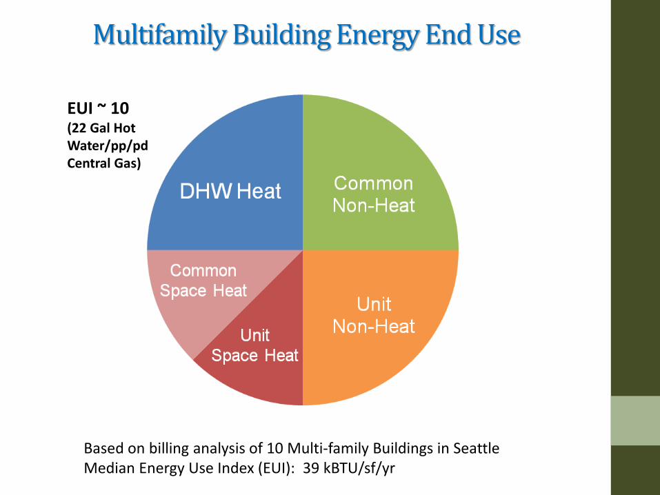
Multifamily Building Energy End Use
Based on billing analysis of 10 Multi-family Buildings in Seattle Median Energy Use Index (EUI): 39 kBTU/sf/yr
EUI ~ 10 (22 Gal Hot Water/pp/pd Central Gas)
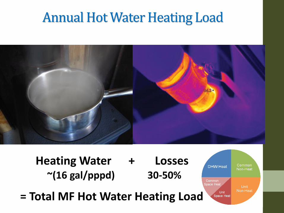
Annual Hot Water Heating Load
Heating Water + Losses
= Total MF Hot Water Heating Load
~(16 gal/pppd) 30-50%

Parts of a Central Hot Water System • Central Plant • Primary Supply • Risers • Balancing • Re-circulation
Central Hot Water Heating System
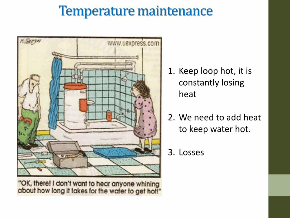
Temperature maintenance
1. Keep loop hot, it is constantly losing heat
2. We need to add heat to keep water hot.
3. Losses
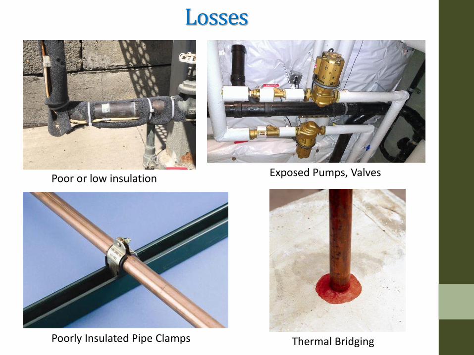
Losses
Poor or low insulation Exposed Pumps, Valves
Thermal Bridging Poorly Insulated Pipe Clamps
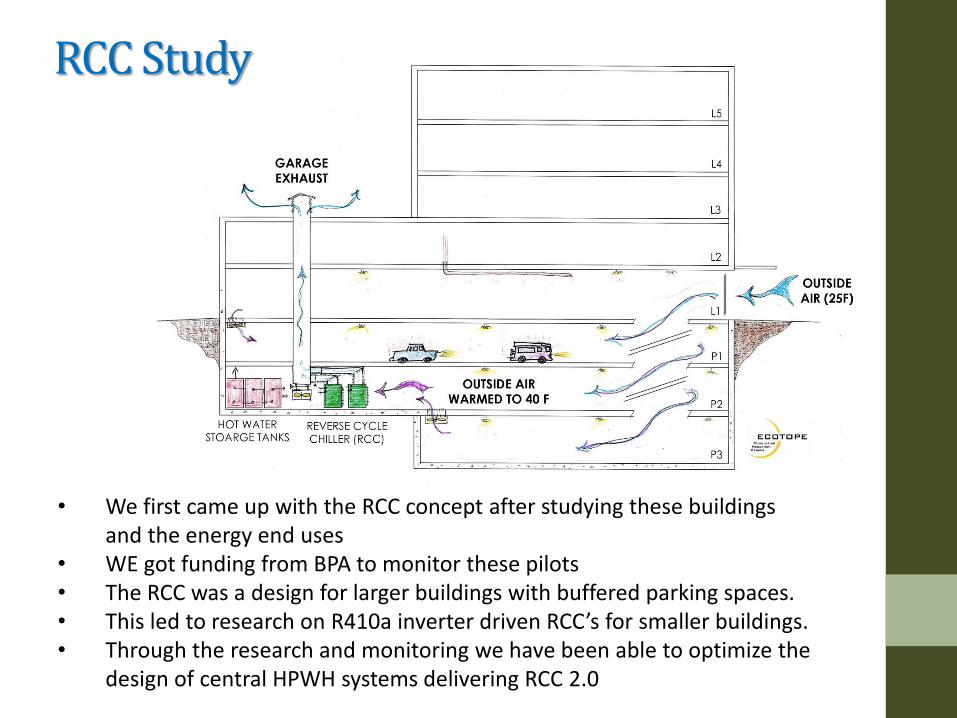
• We first came up with the RCC concept after studying these buildings and the energy end uses
• WE got funding from BPA to monitor these pilots • The RCC was a design for larger buildings with buffered parking spaces. • This led to research on R410a inverter driven RCC’s for smaller buildings. • Through the research and monitoring we have been able to optimize the
design of central HPWH systems delivering RCC 2.0
RCC Study

• Through the research and monitoring we have evolved to RCC 2.0.
RCC-1.0 - 2.30 Seasonal
RCC-2.0 - 2.75 Seasonal
• Decouple the heating water load from the temperature maintenance loads allows optimization of both
RCC Finding
9500
16000
8500
7500
0
5000
10000
15000
20000
25000
Sunset Electric (47%) Stream Uptown (32%)
Losses (watts)
Water Heating Load (watts)

• We started designing RCC’s for smaller buildings and also decided to test out the temp maintenance systems and combine to research and M&V project
• This led to research on R410a inverter driven
RCC’s for smaller buildings and out of that we also arrived at a temperature maintenance study
RCC for smaller buildings
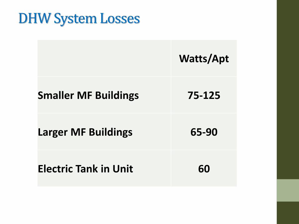
DHW System Losses
Watts/Apt
Smaller MF Buildings 75-125
Larger MF Buildings 65-90
Electric Tank in Unit 60
Ecotope figured out how big the losses were and we came up with test for the Grow Communities MF project. We got BPA involved and designed a double study: Temperature Maintenance Options 1. Traditional Circulation Loop with increased insulation 2. Heat Trace 3. Pipe in a Pipe Daikin Altherma for Central DHW 1. With Recirculation Water Mixed In 2. With only Cold Water Entering Tank
Temperature Maintenance and Heat Pumps Research
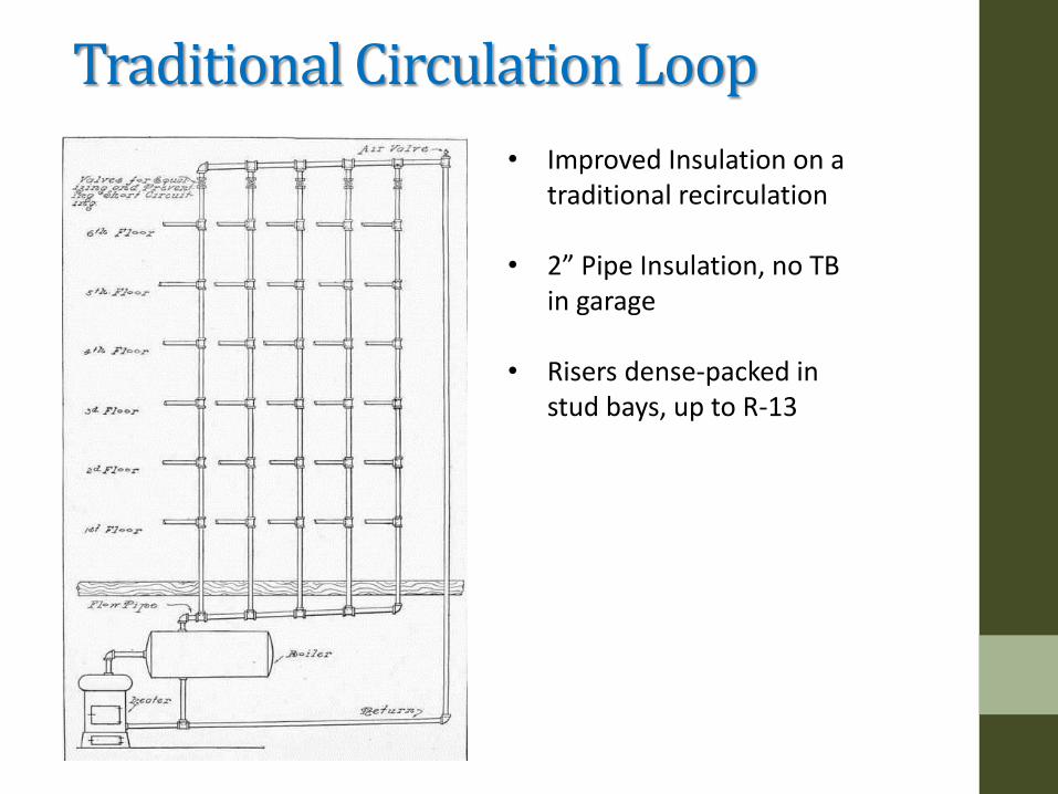
• Improved Insulation on a traditional recirculation
• 2” Pipe Insulation, no TB in garage
• Risers dense-packed in stud bays, up to R-13
Traditional Circulation Loop
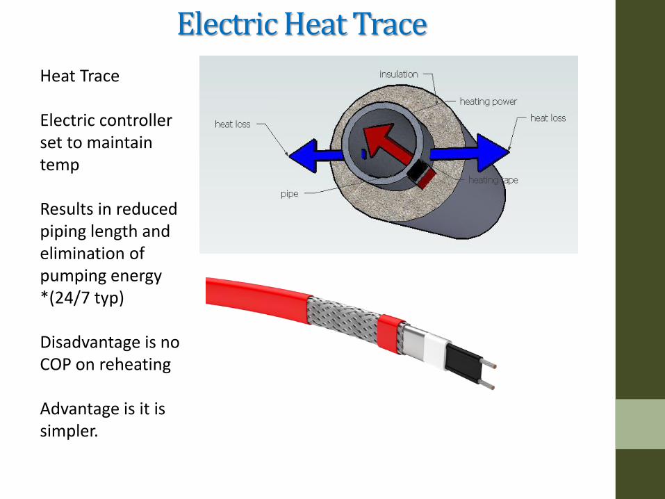
Heat Trace Electric controller set to maintain temp Results in reduced piping length and elimination of pumping energy *(24/7 typ) Disadvantage is no COP on reheating Advantage is it is simpler.
Electric Heat Trace
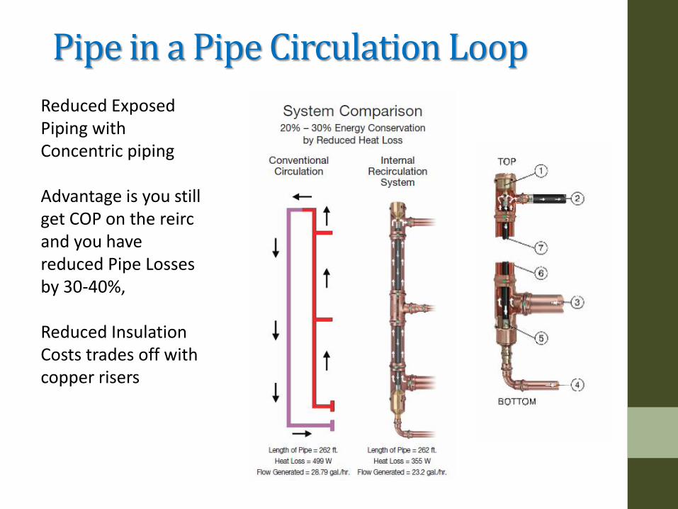
Pipe in a Pipe Circulation Loop
Reduced Exposed Piping with Concentric piping Advantage is you still get COP on the reirc and you have reduced Pipe Losses by 30-40%, Reduced Insulation Costs trades off with copper risers
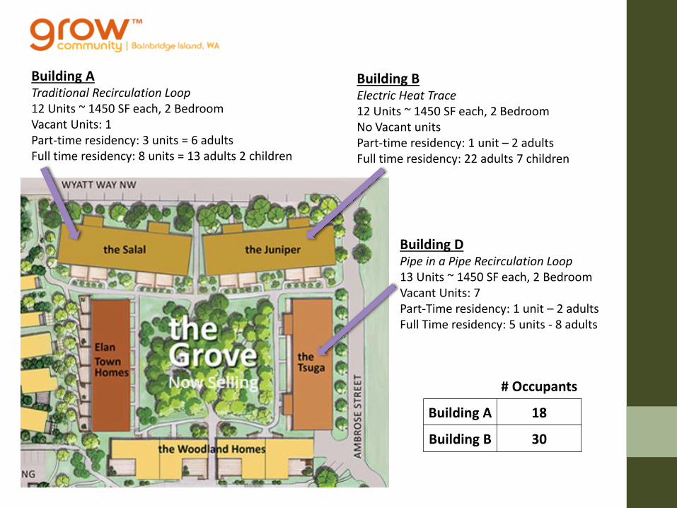
Building A Traditional Recirculation Loop 12 Units ~ 1450 SF each, 2 Bedroom Vacant Units: 1 Part-time residency: 3 units = 6 adults Full time residency: 8 units = 13 adults 2 children
Building B Electric Heat Trace 12 Units ~ 1450 SF each, 2 Bedroom No Vacant units Part-time residency: 1 unit – 2 adults Full time residency: 22 adults 7 children
Building D Pipe in a Pipe Recirculation Loop 13 Units ~ 1450 SF each, 2 Bedroom Vacant Units: 7 Part-Time residency: 1 unit – 2 adults Full Time residency: 5 units - 8 adults
# Occupants
Building A 18
Building B 30

Multi-Family Hot Water Usage

Hot Water Usage Grow Building A
12 Units
Building #
Occupants
Mean DHW/
Day Hot Water /pp/day
A 18 250 13.9
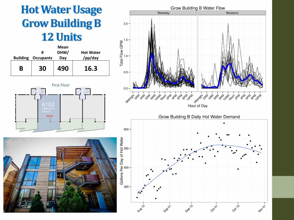
Hot Water Usage Grow Building B
12 Units
Building #
Occupants
Mean DHW/
Day Hot Water /pp/day
B 30 490 16.3
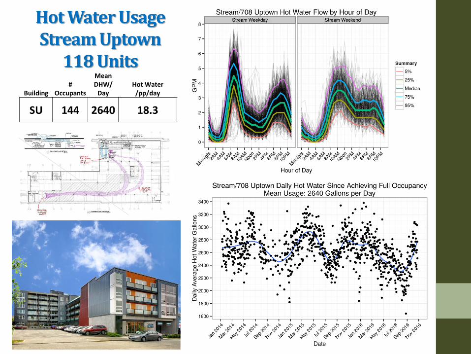
Hot Water Usage Stream Uptown
118 Units
Building #
Occupants
Mean DHW/
Day Hot Water /pp/day
SU 144 2640 18.3
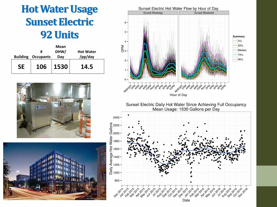
Hot Water Usage Sunset Electric
92 Units
Building #
Occupants
Mean DHW/
Day Hot Water /pp/day
SE 106 1530 14.5
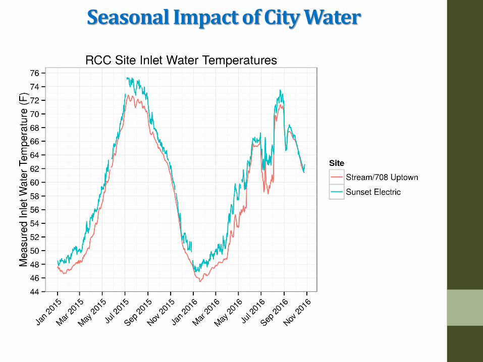
Seasonal Impact of City Water
Findings – Actual Losses
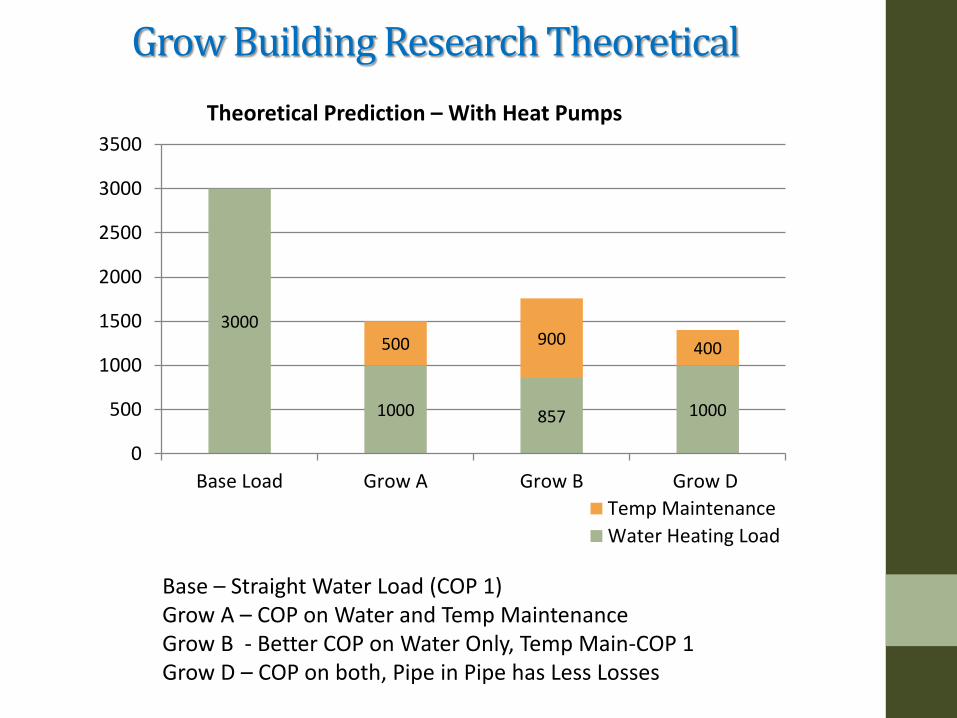
Grow Building Research Theoretical
3000
1000 857 1000
500 900 400
0
500
1000
1500
2000
2500
3000
3500
Base Load Grow A Grow B Grow D
Theoretical Prediction – With Heat Pumps
Temp Maintenance
Water Heating Load
Base – Straight Water Load (COP 1) Grow A – COP on Water and Temp Maintenance Grow B - Better COP on Water Only, Temp Main-COP 1 Grow D – COP on both, Pipe in Pipe has Less Losses

Theoretical Calculated Losses-Grow A HOT WATER HEAT LOSS CALCULATOR
SYSTEM INPUTS BUILDING INPUTS INSULATION INPUTS
SYSTEM NAME
SYSTEM ABBREVIATION
FLUID TEMPERATURE
INDOOR TEMP 70
TAG TYPE K VALUE (BTU-FT/HR-FT2-F)
WALL THICKNESS
(INCH)
PERCENTAGE OF PIPE
INSULATED R VALUE
DOMESTIC COLD WATER
DCW 70 GARAGE TEMP 50
A FIBERGLASS 0.0231 1.5 100% Garage Value
DOMESTIC HOT WATER
DHW 122 B FIBERGLASS 0.0231 2 100% Riser Value
DOMESTIC HOT WATER CIRCULATION
DHWC 118 C
HEATING WATER RETURN
HWR 80 D
HEATING WATER SUPPLY
HWS 90 E
PIPE INFORMATION PIPE SIZE INSULATION HEAT LOSS
TAG SYSTEM MATERIAL LOCATION FLOOR DIAMETER
(INCH) LENGTH
(FT) QUANTITY
90 DEG BENDS
TAG K VALUE (BTU-FT/HR-FT2-F)
PERCENT INSULATED
LINEAR (BTU/HR-FT)
TOTAL (BTU/HR)
Primary Supply DHW CPVC Garage Garage 1 1/2 35.5 1 0 A 0.0231 100% 9.51 337.51 Header in Garage DHW CPVC Garage Garage 1 1/2 23.5 1 0 A 0.0231 100% 9.51 223.42 Header in Garage DHW CPVC Garage Garage 1 1/4 94.0 1 0 A 0.0231 100% 8.53 802.29 Riser Supply DHW CPVC Unit Unit 1 1/4 6.0 4 0 B 0.0231 100% 5.26 126.16 Riser Supply DHW CPVC Unit Unit 1 10.0 4 0 B 0.0231 100% 4.69 187.48 Riser Supply DHW CPVC Unit Unit 3/4 10.0 4 0 B 0.0231 100% 4.09 163.47 Riser Return DHW CPVC Unit Unit 3/4 27.0 4 0 B 0.0231 100% 4.09 441.38 Return in Garage DHW CPVC Unit Unit 3/4 165.0 1 0 B 0.0231 100% 4.09 674.32
N/A N/A N/A N/A N/A 1 3/32 371.0 20.0 0.0 N/A 0.023 100% 49.75 2956
Supply Loop – 2000 BTU/hr Return Loop – 1000 BTU/hr Other Losses - 2500 Btu/hr
Total ~ 5500 Btu/hr All Losses are Surface Area * U Value
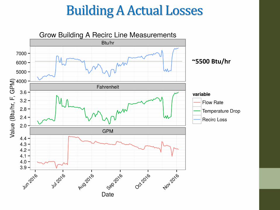
Building A Actual Losses
~5500 Btu/hr
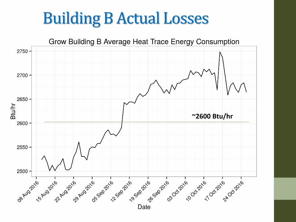
Building B Actual Losses
~2600 Btu/hr
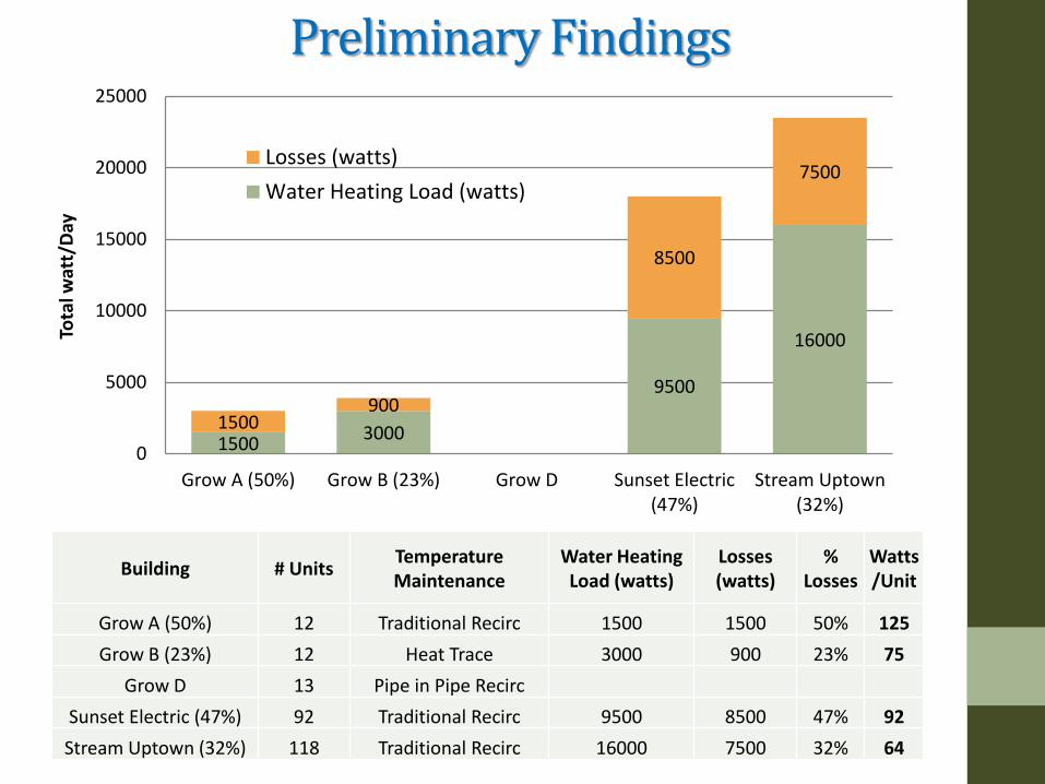
Preliminary Findings
1500 3000
9500
16000
1500 900
8500
7500
0
5000
10000
15000
20000
25000
Grow A (50%) Grow B (23%) Grow D Sunset Electric(47%)
Stream Uptown(32%)
Tota
l wat
t/D
ay
Losses (watts)
Water Heating Load (watts)
Building # Units Temperature Maintenance
Water Heating Load (watts)
Losses (watts)
% Losses
Watts/Unit
Grow A (50%) 12 Traditional Recirc 1500 1500 50% 125
Grow B (23%) 12 Heat Trace 3000 900 23% 75
Grow D 13 Pipe in Pipe Recirc
Sunset Electric (47%) 92 Traditional Recirc 9500 8500 47% 92
Stream Uptown (32%) 118 Traditional Recirc 16000 7500 32% 64

Preliminary Findings
125
75
0
92
64 60
0
20
40
60
80
100
120
140
Grow A(50%)
Grow B(23%)
Grow D SunsetElectric(47%)
StreamUptown
(32%)
ElectricWaterHeater
Losses Watts/Unit
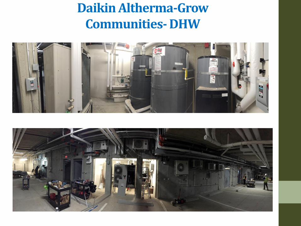
Daikin Altherma-Grow Communities- DHW
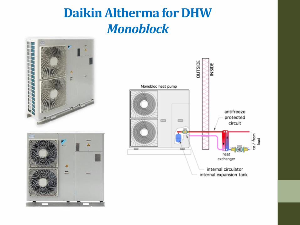
Daikin Altherma for DHW Monoblock
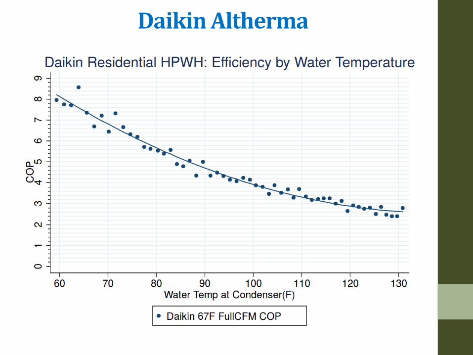
Daikin Altherma

Daikin Altherma
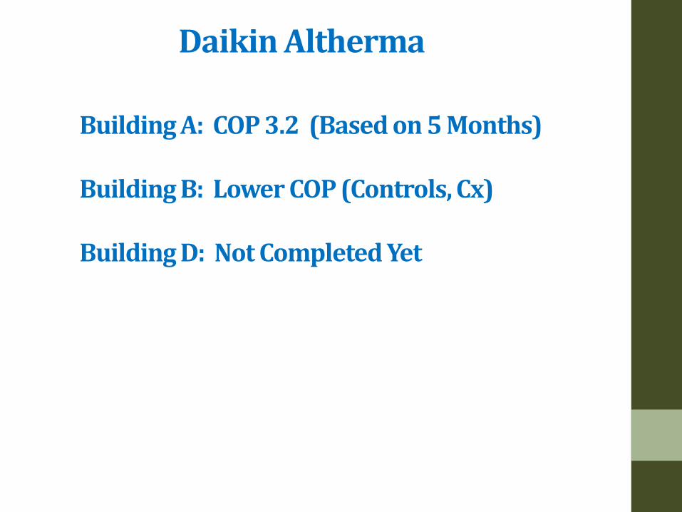
Building A: COP 3.2 (Based on 5 Months) Building B: Lower COP (Controls, Cx) Building D: Not Completed Yet
Daikin Altherma

Design Considerations
• Back to back bathrooms sharing a single stack reduces UA by factor of 2
• Locate hot water storage and primary distribution in heated space to capture losses ½ the year
• Plan for super-insulated hot water piping runs, Risers- 2x8
studbays, Adequate room for insulated pipe clamps • Consider Distributed Plants versus Single Central Plant.
(closer to use, smaller piping)
• Use heat pumps when heating with utility provided power, lowest carbon
Design Considerations Programming and Design
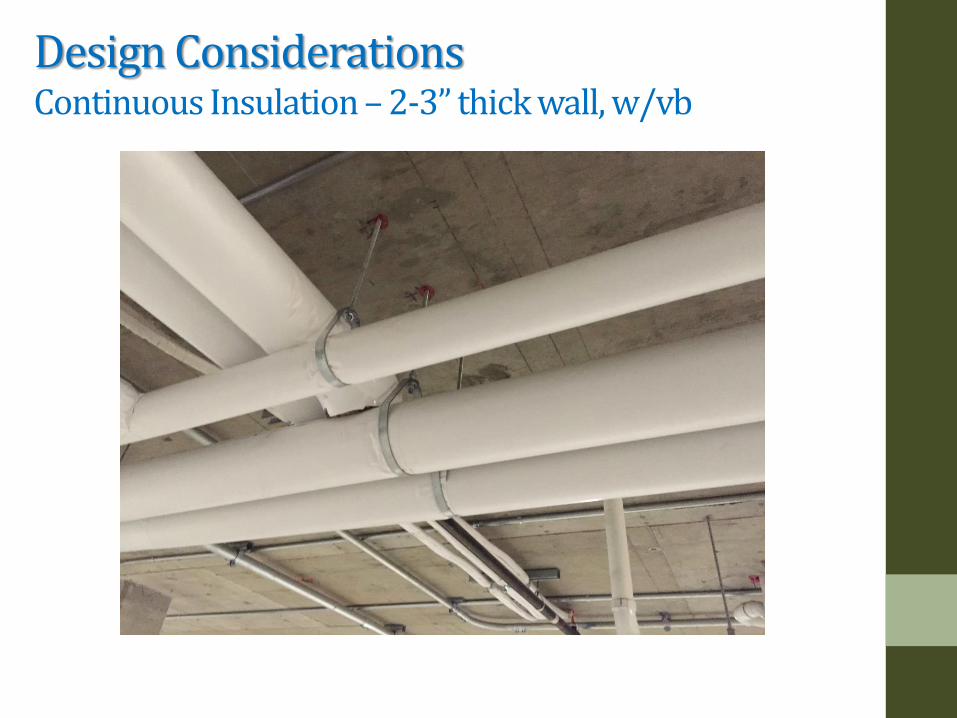
Design Considerations Continuous Insulation – 2-3” thick wall, w/vb
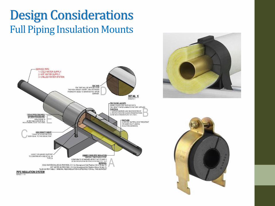
Design Considerations Full Piping Insulation Mounts
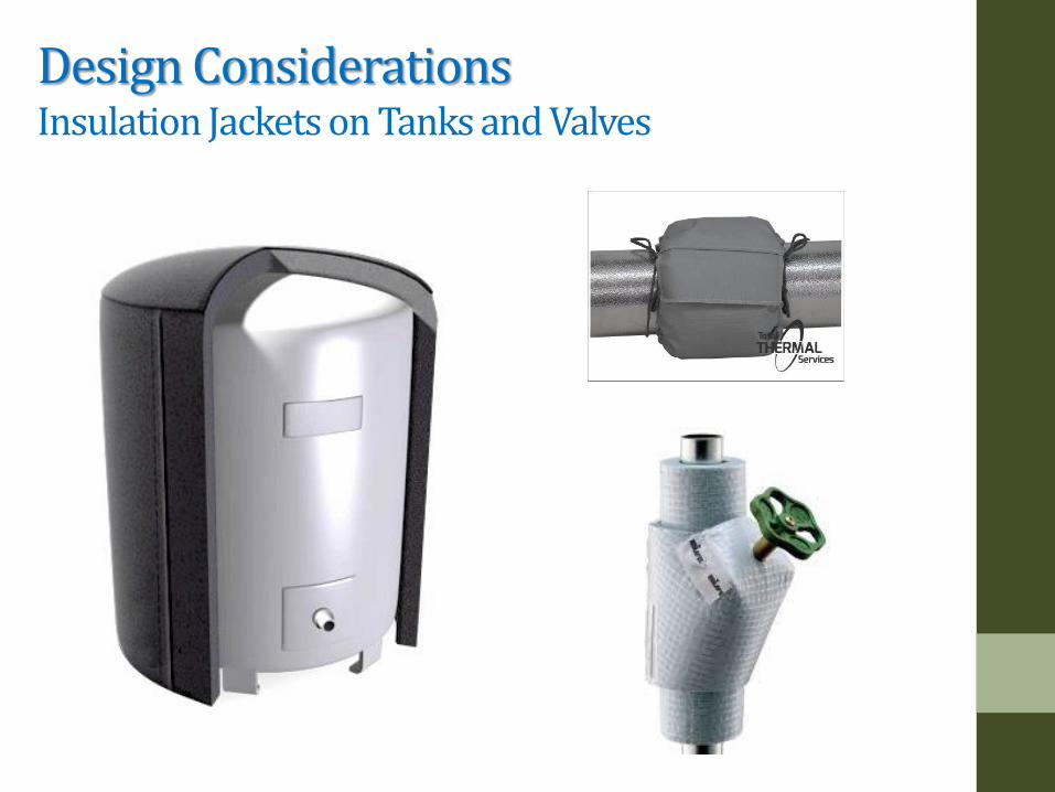
Design Considerations Insulation Jackets on Tanks and Valves

Piping Insulation Requirements – Too Low
Delta T of 50-70 degrees year round We insulate houses to R-20 and 30 for 1 week of 47F delta T Pipe Insulation is Cost Effective, Need More
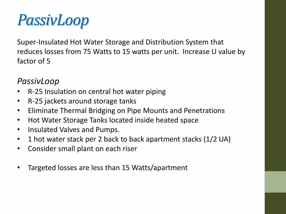
Super-Insulated Hot Water Storage and Distribution System that reduces losses from 75 Watts to 15 watts per unit. Increase U value by factor of 5
PassivLoop • R-25 Insulation on central hot water piping • R-25 jackets around storage tanks • Eliminate Thermal Bridging on Pipe Mounts and Penetrations • Hot Water Storage Tanks located inside heated space • Insulated Valves and Pumps. • 1 hot water stack per 2 back to back apartment stacks (1/2 UA) • Consider small plant on each riser • Targeted losses are less than 15 Watts/apartment
PassivLoop
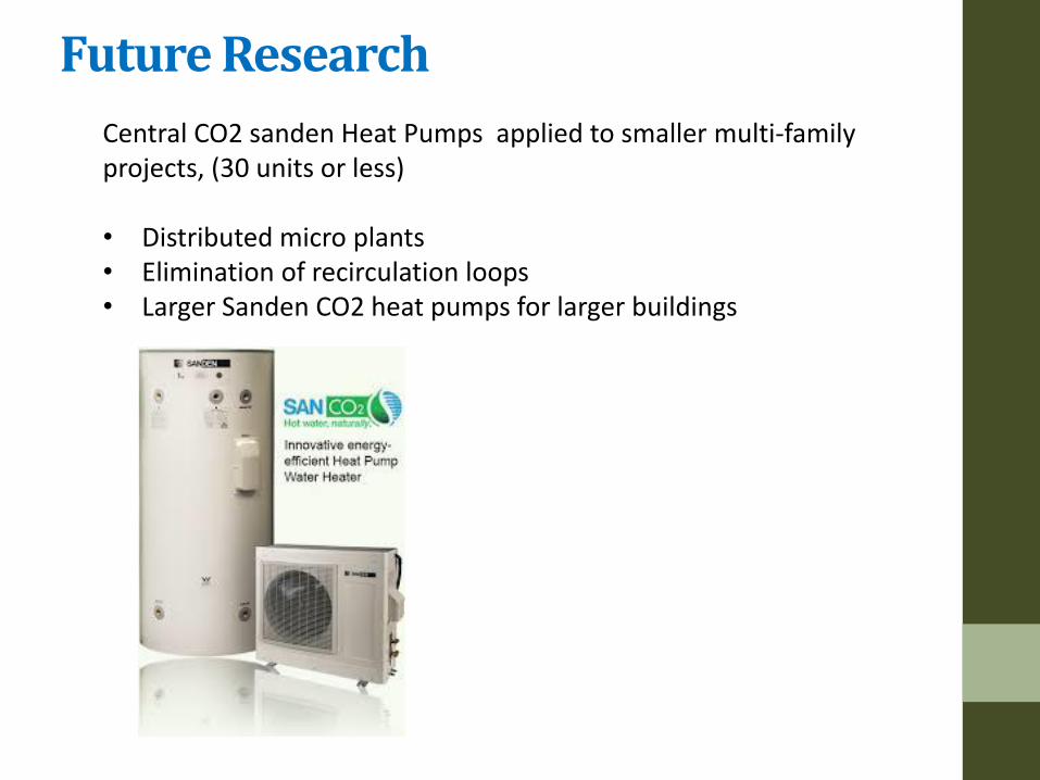
Central CO2 sanden Heat Pumps applied to smaller multi-family projects, (30 units or less) • Distributed micro plants • Elimination of recirculation loops • Larger Sanden CO2 heat pumps for larger buildings
Future Research
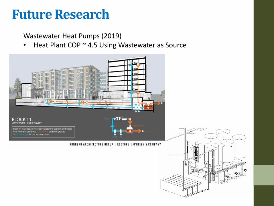
Wastewater Heat Pumps (2019) • Heat Plant COP ~ 4.5 Using Wastewater as Source
Future Research

Questions/Comments:
Shawn Oram, PE 206.596.4703
Ecotope.com