central seam plus central-loc - central states mfg.€¦ · central states manufacturing, inc....
TRANSCRIPT

Central-LocSnaps together
Central Seam PlusField seamed
24" or 18" COVERAGE
3"
GUID_PROD_CENTRALLOC-SEAM_180201D C
3"
24" or 18" COVERAGE
Central Seam Plus®
Central-Loc®
Product GuideHELPFUL INFORMATION ON PANELS, TRIMS, GUTTERS AND ACCESSORIES
Copyright © 2018 by Central States Manufacturing, Inc.


C E N T R A L S T A T E S M A N U F A C T U R I N G , I N C .E f f e c t i v e 0 2 / 2 0 1 8 • I n f o r m a t i o n s u b j e c t t o c h a n g e 3
OUR MISSIONThe men and women at
Central States Manufacturing, Inc. would like to welcome you.
Central States Manufacturing, Inc. is a 100% employee-owned company devoted to the personal growth and well-being of our owners. We are dedicated to increasing the value of our company by making Raving Fans of our customers through exceeding their expectations, being easy to do business with, demonstrating excellence in all aspects of our business and being committed to improving their business.
It is our promise to maintain honesty and integrity with everyone our lives may touch. With thanksgiving for the blessings we have been given, we are committed to serving the communities where we live and work by giving back a portion of our time, talents and profits.

C E N T R A L S T A T E S M A N U F A C T U R I N G , I N C .E f f e c t i v e 0 2 / 2 0 1 8 • I n f o r m a t i o n s u b j e c t t o c h a n g e 4
Information in the catalog may vary by plant location.
Please call your salesperson to verify product availability.
The application and detail drawings in this manual are strictly for illustration purposes and may not be applicable to all building designs or product installations. Projects should conform to local building codes. Central States Manufacturing is not responsible for the performance of the material if it is not installed correctly.
Information contained in this booklet was in effect at the time of publication and is subject to change without notice.
Delivery / Storage & Handling / Cutting . . . . . . . . . . . 05Central-Loc Information. . . . . . . . . . . . . . . . . . . . . . . . . . . 06 Allowable Live Loads . . . . . . . . . . . . . . . . . . . . . . . . . 07 Engineering . . . . . . . . . . . . . . . . . . . . . . . . . . . . . . . . . . 08 UL Ratings. . . . . . . . . . . . . . . . . . . . . . . . . . . . . . . . . . . . 09Central Seam Plus Information . . . . . . . . . . . . . . . . . . . . 10 Allowable Live Loads . . . . . . . . . . . . . . . . . . . . . . . . . 11 Engineering . . . . . . . . . . . . . . . . . . . . . . . . . . . . . . . . . . 12 UL Ratings. . . . . . . . . . . . . . . . . . . . . . . . . . . . . . . . . . . . 13Square Conversions . . . . . . . . . . . . . . . . . . . . . . . . . . . . . . . 14-15Trim . . . . . . . . . . . . . . . . . . . . . . . . . . . . . . . . . . . . . . . . . . . . . . 16-20Gutters . . . . . . . . . . . . . . . . . . . . . . . . . . . . . . . . . . . . . . . . . . . 21Eave Plates. . . . . . . . . . . . . . . . . . . . . . . . . . . . . . . . . . . . . . . . 22Clips . . . . . . . . . . . . . . . . . . . . . . . . . . . . . . . . . . . . . . . . . . . . . . 23Rake Support . . . . . . . . . . . . . . . . . . . . . . . . . . . . . . . . . . . . . 24Accessories . . . . . . . . . . . . . . . . . . . . . . . . . . . . . . . . . . . . . . . 25-27
Notice:
INDEX
C E N T R A L S T A T E S M A N U F A C T U R I N G , I N C .E f f e c t i v e 0 2 / 2 0 1 8 • I n f o r m a t i o n s u b j e c t t o c h a n g e 5
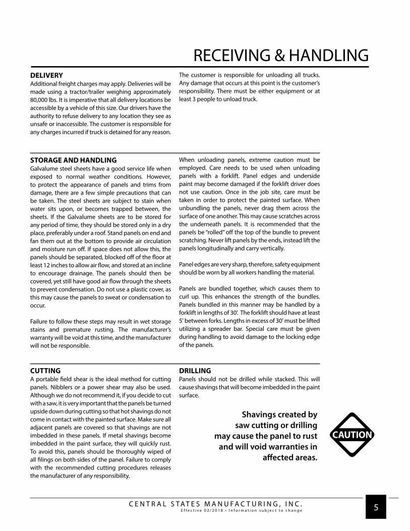
RECEIVING & HANDLINGDELIVERYAdditional freight charges may apply. Deliveries will be made using a tractor/trailer weighing approximately 80,000 lbs. It is imperative that all delivery locations be accessible by a vehicle of this size. Our drivers have the authority to refuse delivery to any location they see as unsafe or inaccessible. The customer is responsible for any charges incurred if truck is detained for any reason.
The customer is responsible for unloading all trucks. Any damage that occurs at this point is the customer’s responsibility. There must be either equipment or at least 3 people to unload truck.
STORAGE AND HANDLINGGalvalume steel sheets have a good service life when exposed to normal weather conditions. However, to protect the appearance of panels and trims from damage, there are a few simple precautions that can be taken. The steel sheets are subject to stain when water sits upon, or becomes trapped between, the sheets. If the Galvalume sheets are to be stored for any period of time, they should be stored only in a dry place, preferably under a roof. Stand panels on end and fan them out at the bottom to provide air circulation and moisture run off. If space does not allow this, the panels should be separated, blocked off of the floor at least 12 inches to allow air flow, and stored at an incline to encourage drainage. The panels should then be covered, yet still have good air flow through the sheets to prevent condensation. Do not use a plastic cover, as this may cause the panels to sweat or condensation to occur.
Failure to follow these steps may result in wet storage stains and premature rusting. The manufacturer’s warranty will be void at this time, and the manufacturer will not be responsible.
When unloading panels, extreme caution must be employed. Care needs to be used when unloading panels with a forklift. Panel edges and underside paint may become damaged if the forklift driver does not use caution. Once in the job site, care must be taken in order to protect the painted surface. When unbundling the panels, never drag them across the surface of one another. This may cause scratches across the underneath panels. It is recommended that the panels be “rolled” off the top of the bundle to prevent scratching. Never lift panels by the ends, instead lift the panels longitudinally and carry vertically.
Panel edges are very sharp, therefore, safety equipment should be worn by all workers handling the material.
Panels are bundled together, which causes them to curl up. This enhances the strength of the bundles. Panels bundled in this manner may be handled by a forklift in lengths of 30'. The forklift should have at least 5' between forks. Lengths in excess of 30' must be lifted utilizing a spreader bar. Special care must be given during handling to avoid damage to the locking edge of the panels.
CUTTINGA portable field shear is the ideal method for cutting panels. Nibblers or a power shear may also be used. Although we do not recommend it, if you decide to cut with a saw, it is very important that the panels be turned upside down during cutting so that hot shavings do not come in contact with the painted surface. Make sure all adjacent panels are covered so that shavings are not imbedded in these panels. If metal shavings become imbedded in the paint surface, they will quickly rust. To avoid this, panels should be thoroughly wiped of all filings on both sides of the panel. Failure to comply with the recommended cutting procedures releases the manufacturer of any responsibility.
DRILLINGPanels should not be drilled while stacked. This will cause shavings that will become imbedded in the paint surface.
Shavings created bysaw cutting or drilling
may cause the panel to rust and will void warranties in
affected areas.
CAUTION

C E N T R A L S T A T E S M A N U F A C T U R I N G , I N C .E f f e c t i v e 0 2 / 2 0 1 8 • I n f o r m a t i o n s u b j e c t t o c h a n g e 6
Central-Loc is a snap-together trapezoidal roofing system available in 24" standard coverage and an optional 18" panel. Its floating clips allow for thermal roof expansion and contraction during extreme temperature changes. A factory applied sealant insures a weather-tight and secure lap. This panel can be used for both new construction and retrofit. Central-Loc is manufactured from Galvalume® which offers two to four times the corrosion resistance of galvanized steel.
• Weather-tight 3" high standing seam with concealed clips and fasteners
• Factory applied hot melt seam and clip sealant
• Large selection of clip sizes to accommodate various types of construction and insulation thicknesses
• Panels can be pre-punched, combined with self-engaging backup plates for ease of installation.
• No field seaming
• Reversible end-for-end panels so each side of the roof can be installed simultaneously.
• Panels are factory notched for ease of installation at the endlap
• Comprehensive step-by-step erection manuals come with each Standing Seam order.
3"
24" or 18" COVERAGE
CENTRAL-LOC

C E N T R A L S T A T E S M A N U F A C T U R I N G , I N C .E f f e c t i v e 0 2 / 2 0 1 8 • I n f o r m a t i o n s u b j e c t t o c h a n g e 7
Coverage Width - 24" with minor ribs - 6 pre-punched holes or no punching
18" with minor ribs - 5 pre-punched holes or no punching
Minimum Slope - 1/4:12
Panel Attachment - Low, high (fixed or floating), or utility (no insulation clearance)
Panel Substrate - Galvalume®
Gauge - 24
Finishes - Smooth with minor ribs
Panel Coating - Fluropon® or arcylic Galvalume®
Note: Oil canning in the flat area of the panels is common to the industry and does not affect the integrity of the panel. Therefore, oil canning is not a reason for rejection.
ALLOWABLE LIVE LOADS
SPAN
TYPE
1-SPAN
2-SPAN
3-SPAN
4-SPAN
LOAD
TYPE
LIVE LOAD
LIVE LOAD
LIVE LOAD
LIVE LOAD
2.5
204.0
204.0
204.0
204.0
3.0
170.0
170.0
170.0
170.0
3.5
145.7
145.7
145.7
145.7
4.0
127.5
118.7
127.5
127.5
4.5
113.3
93.8
113.3
109.4
5.0
92.3
75.9
94.9
88.6
5.5
76.3
62.8
78.4
73.2
Span (ft)
24 Gauge (Fy = 50 KSI) - All loads in pounds per square foot.
Allowable loads are based on uniform span lengths and panel yield strength (Fy) of 50 ksi. LIVE LOAD is an allowable live load limited by shear & bending or web crippling. Above loads consider a maximum deflection ratio of L/180. Weight of the panel has not been deducted from allowable loads. Contact CSMI for wind uplift values.
CENTRAL-LOC - 24" COVERAGE
SPAN
TYPE
1-SPAN
2-SPAN
3-SPAN
4-SPAN
LOAD
TYPE
LIVE LOAD
LIVE LOAD
LIVE LOAD
LIVE LOAD
2.5
272.0
272.0
272.0
272.0
3.0
226.7
226.7
226.7
226.7
3.5
194.3
194.3
194.3
194.3
4.0
170.0
158.8
170.0
170.0
4.5
145.8
125.5
156.9
146.5
5.0
118.1
101.6
127.1
118.6
5.5
97.6
84.0
105.0
98.0
Span (ft)
24 Gauge (Fy = 50 KSI) - All loads in pounds per square foot.
CENTRAL-LOC - 18" COVERAGE
CENTRAL-LOC

C E N T R A L S T A T E S M A N U F A C T U R I N G , I N C .E f f e c t i v e 0 2 / 2 0 1 8 • I n f o r m a t i o n s u b j e c t t o c h a n g e 8
Application and design details are for illustration purposes only, and may not be appropriate for all environmental conditions or building designs. Projects should be engineered to conform to applicable building codes, regulations, and accepted industry practices.
CAUTION
I M P O R T A N T - R E A D T H I S F I R S T
Central-Loc is a snap together system. Use of a mechanical seaming toolon the Central-Loc system will void all warranties.
LOW FIXED SYSTEMDouble slope buildings 200' wide or less and single slope buildings 100' wide or less, with or without a 3/8" thermal spacer. See Insulation/Thermal Spacer Selection Chart below.
HIGH FIXED SYSTEMDouble slope buildings 200' wide or less and single slope buildings 100' wide or less, with 3/8", 5/8", or 1" thermal spacers. See Insulation/Thermal Spacer Selection Chart below.
In order to design, quote or order a Central-Loc roof system, you must determine which system you need, based on building width and insulation requirements.
Thermal calculations should be performed for each project to ensure that the thermal movement of the roof is not greater than the floating clip’s capacity. Various densities of blanket insulation may affect the installation and or the appearance of a metal roof system. The installer is responsible for selecting the proper clip and thermal spacer for their conditions.
Fixed systems utilize fixed clips that do not allow the roof panels to float on the substructure. For this reason, use fixed systems only on pre-engineered metal buildings with purlins, subject to the building width restrictions outlined above. Do not use fixed systems on buildings with bar joist construction, wood decks or metal decks.
LOW FLOATING SYSTEMDouble slope buildings over 200' wide or single slope buildings over 150' wide, with or without 3/8" thermal spacer. See Insulation/Thermal Spacer Selection Chart below.
HIGH FLOATING SYSTEM Double slope buildings over 200' wide or single slope buildings over 150' wide, with 3/8", 5/8" or 1" thermal spacer. See Insulation/Thermal Spacer Selection Chart below.
INSULATION/THERMAL SPACER SELECTION CHART Insulation Thickness Low System High System No Insulation 3/8" Thermal Spacer High System Not Recommended
3" Insulation Thermal Spacer Not Recommended 1" Thermal Spacer Recommended
4" Insulation Thermal Spacer Not Recommended 5/8" Thermal Spacer Recommended
6" Insulation Low System Not Recommended 3/8" Thermal Spacer Recommended
NOTES: 1. As with all standing seam roof systems, sound attenuation (example: blanket insulation) is required between the panel and the substructure
to prevent “roof rumble” during windy conditions. Some composite roof systems may require additional acoustical consideration to ensure that thermal vibration noises are isolated from the building interior. Contact your architect and/or engineer for proper acoustical design.
2. The following are examples of conditions that may cause condensation: (A) Projects where outside winter temperatures below 40°F are anticipated and where average winter interior relative humidity of 45% or greater is expected. (B) Building usages with high humidity interiors, such as indoor swimming pools, textile manufacturing operations, food paper or other wet-process industrial plants. (C) Construction elements that may release moisture after the roof is installed, such as interior concrete and masonry, plaster finishes and fuel burning heaters. Manufacturer is not responsible for determining if condensation will be an issue on any particular application.
THERMAL SPACER DISCLAIMERThe above thermal spacer chart is intended to be used as a general guideline only. Because of the various densities of insulation currently available, the manufacturer cannot guarantee that this chart will be accurate in all situations. Further, the manufacturer does not specifically require that the roofing contractor use thermal spacers with its Central-Loc roof system. However, please review the following information: • Although the manufacturer does not require a thermal spacer, the architect or building owner may. • In certain environments, the compression of the fiberglass insulation, without a thermal spacer, may create a thermal break which can cause
condensation to form on the purlins/joists. • On uninsulated buildings, eliminating the thermal spacer: (1) may cause “roof rumble” and (2) you may encounter problems holding panel module. • When a high clip is used without a thermal spacer: (1) you may encounter problems holding panel module and (2) foot traffic on the panel ribs
may result in bent clips. • Using a low clip with too much insulation or too thick a thermal spacer: (1) may cause “purlin read” (2) may cause difficulty in properly installing
the panel side laps, and (3) you may encounter problems holding panel module.
CENTRAL-LOC ENGINEERING

C E N T R A L S T A T E S M A N U F A C T U R I N G , I N C .E f f e c t i v e 0 2 / 2 0 1 8 • I n f o r m a t i o n s u b j e c t t o c h a n g e 9
Constructionnumber
165180B205
205A286
308B534535536537541
Panel Width (Inches)
2424242424242424242424
Gauge
24 min.24 min.24 min.24 min.24 min.24 min.24 min.24 min.24 min.24 min.26 min.
Clip Type
BAABCABABBB
Clip Spacing
5'-0"5'-0"5'-0"5'-0"5'-0"5'-0"
5'-0 1/4"5'-0 1/4"
5'-0"5'-0 1/4"
5'-0"
Substrate
Open FramingComposite
Open FramingOpen Framing
PlywoodComposite
Open FramingOpen Framing
CompositeCompositePlywood
UL-2218 Impact Resistance
Class 4Class 4Class 4Class 4Class 4Class 4Class 4Class 4Class 4Class 4Class 4
UL-263Fire Rating
Class A Class AClass AClass AClass AClass AClass AClass AClass AClass AClass A
UL-580 Rating
Class 90Class 90Class 90Class 90Class 90Class 90Class 90Class 90Class 90Class 90Class 90
NOTES: 1. Wind uplift test procedures are in accordance with Underwriters Laboratories Standard UL-580 under “Tests For Uplift Resistance of Roof Assemblies.” 2. A detailed installation method is available for each Construction Number above and can be found in the UL Roofing Materials and Systems Directory or at http://www.ul.com. The panels must be installed in a certain manner to achieve the published results.
3. The panel qualifies for a Class A fire rating in compliance with Underwriters Laboratories Standard UL-263.
4. The panel system is listed under the following Fire Resistance Design Numbers: P224, P225, P227, P230, P233, P237, P265, P268, P508, P510, P512, P701, P711, P715, P717, P720, P722, P724, P726, P731, P734, P736, P801, P803, P814, P815, P819, P821, P823. Refer to the UL Fire Resistance Directory for specific construction methods and hourly ratings. 5. Central-Loc panels carry a Class 4 rating under UL-2218 “Test Standard for Impact Resistance”.
Clip Type: A (Fixed or Floating); B (Floating); C (Utility).
CENTRAL-LOC
ICBO APPROVALThe ICBO Evaluation Service, Inc., has approved the Central-Loc roofing system details, engineering, calculations, computer printouts and product data. This information has been found to comply with 1997 UBC Code and is listed in evaluation report number ER-5409. A copy of this report is available on request.
FLORIDA BUILDING CODE PRODUCT APPROVALRoofing System details and engineering load tables have been examined by the State of Florida and comply with Florida Building Code Product Approval Number FL 14016.2.
UNDERWRITERS LABORATORIES APPROVAL

C E N T R A L S T A T E S M A N U F A C T U R I N G , I N C .E f f e c t i v e 0 2 / 2 0 1 8 • I n f o r m a t i o n s u b j e c t t o c h a n g e 10
Central Seam Plus is a field seamed trapezoidal roofing system available in 24" standard coverage and an optional 18" panel. Its floating clips allow for thermal roof expansion and contraction during extreme temperature changes. A factory applied sealant insures a weather-tight and secure lap. This panel can be used for both new construction and retrofit. Central Seam Plus is manufactured from Galvalume® which offers two to four times the corrosion resistance of galvanized steel.
• Central Seam Plus begins and ends in the high, reducing the risk of leakage at the rake that can occur when finishing in the low.
• Factory applied hot melt seam and clip sealant
• Large selection of clip sizes to accommodate various types of construction and insulation thicknesses
• A standard clip allows for a total of two inches of thermal movement and is constructed from 14 gauge material. The clip provides a 3/8" or 1 3/8" clearance at the purlin to reduce water ponding on low pitch roofs. Constructed from 12 gauge material, this clip is an integral part of maintaining panel module.
• Panels can be pre-punched, combined with self-engaging backup plates for ease of installation.
• Reversible end-for-end panels so each side of the roof can be installed simultaneously.
• Panels are factory notched for ease of installation at the endlap
• Comprehensive step-by-step erection manuals come with each Standing Seam order.
24" or 18" COVERAGE
3"
CENTRAL SEAM PLUS

C E N T R A L S T A T E S M A N U F A C T U R I N G , I N C .E f f e c t i v e 0 2 / 2 0 1 8 • I n f o r m a t i o n s u b j e c t t o c h a n g e 11
Coverage Width - 24" with minor ribs - 6 pre-punched holes or no punching
18" with minor ribs - 5 pre-punched holes or no punching
Minimum Slope - 1/4:12
Panel Attachment - Low or high (floating)
Panel Substrate - Galvalume®
Gauge - 24
Finishes - Smooth with minor ribs
Panel Coating - Fluropon® or arcylic Galvalume®
Note: Oil canning in the flat area of the panels is common to the industry and does not affect the integrity of the panel. Therefore, oil canning is not a reason for rejection.
ALLOWABLE LIVE LOADS
SPAN
TYPE
1-SPAN
2-SPAN
3-SPAN
4-SPAN
LOAD
TYPE
LIVE LOAD
LIVE LOAD
LIVE LOAD
LIVE LOAD
2.5
204.0
204.0
204.0
204.0
3.0
170.0
170.0
170.0
170.0
3.5
145.7
145.7
145.7
145.7
4.0
127.5
123.4
127.5
127.5
4.5
113.3
97.5
113.3
113.3
5.0
102.0
79.0
98.7
92.2
5.5
86.3
65.3
81.6
76.2
Span (ft)
24 Gauge (Fy = 50 KSI) - All loads in pounds per square foot.
Allowable loads are based on uniform span lengths. LIVE LOAD is limited by bending, shear, combined shear & bending, or web crippling. Above loads consider a maximum deflection ratio of L/180. Panel weight has not been deducted from allowable loads. The use of any field seaming machine other than those provided by the manufacturer will void all engineering data. Contact CSMI for wind uplift values.
CENTRAL SEAM PLUS - 24" COVERAGE
SPAN
TYPE
1-SPAN
2-SPAN
3-SPAN
4-SPAN
LOAD
TYPE
LIVE LOAD
LIVE LOAD
LIVE LOAD
LIVE LOAD
2.5
272.0
272.0
272.0
272.0
3.0
226.7
226.7
226.7
226.7
3.5
194.3
194.3
194.3
194.3
4.0
170.0
163.8
170.0
170.0
4.5
151.1
129.4
151.1
151.0
5.0
131.9
104.8
131.0
122.3
5.5
109.0
86.6
108.3
101.1
Span (ft)
24 Gauge (Fy = 50 KSI) - All loads in pounds per square foot.
CENTRAL SEAM PLUS - 18" COVERAGE
Seamer rental information available on our website
CENTRAL SEAM PLUS

C E N T R A L S T A T E S M A N U F A C T U R I N G , I N C .E f f e c t i v e 0 2 / 2 0 1 8 • I n f o r m a t i o n s u b j e c t t o c h a n g e 12
INSULATION/THERMAL SPACER SELECTION CHART Insulation Thickness Low System High System No Insulation 3/8" Thermal Spacer High System Not Recommended
3" Insulation Thermal Spacer Not Recommended 1" Thermal Spacer Recommended
4" Insulation Thermal Spacer Not Recommended 5/8" Thermal Spacer Recommended
6" Insulation Low System Not Recommended 3/8" Thermal Spacer Recommended
8" Insulation Low System Not Recommended Thermal Spacer Not Recommended
10" Insulation Low System Not Recommended High System Not Recommended
12" Insulation Low System Not Recommended High System Not Recommended
Application and design details are for illustration purposes only, and may not be appropriate for all environmental conditions or building designs. Projects should be engineered to conform to applicable building codes, regulations, and accepted industry practices.
CAUTION
I M P O R T A N T - R E A D T H I S F I R S T
The use of any field seaming machine other than that rentedfrom our approved seamer listed on our website may damage the panels,
void all warranties and will void all engineering data.
In order to design, quote or order a Central Seam Plus roof system, you must determine which system you need, based on building width and insulation requirements.
Thermal calculations should be performed for each project to ensure that the thermal movement of the roof is not greater than the floating clip’s capacity. Various densities of blanket insulation may affect the installation and or the appearance of a metal roof system. The installer is responsible for selecting the proper clip and thermal spacer for their conditions.
NOTES: 1. As with all standing seam roof systems, sound attenuation (example: blanket insulation) is required between the panel
and the substructure to prevent “roof rumble” during windy conditions. Some composite roof systems may require additional acoustical consideration to ensure that thermal vibration noises are isolated from the building interior. Contact your architect and/or engineer for proper acoustical design.
2. The following are examples of conditions that may cause condensation: (A) Projects where outside winter temperatures below 40°F are anticipated and where average winter interior relative humidity of 45% or greater is expected. (B) Building usages with high humidity interiors, such as indoor swimming pools, textile manufacturing operations, food paper or other wet-process industrial plants. (C) Construction elements that may release moisture after the roof is installed, such as interior concrete and masonry, plaster finishes and fuel burning heaters. Manufacturer is not responsible for determining if condensation will be an issue on any particular application.
THERMAL SPACER DISCLAIMERThe above thermal spacer chart is intended to be used as a general guideline only. Because of the various densities of insulation currently available, the manufacturer cannot guarantee that this chart will be accurate in all situations. Further, the manufacturer does not specifically require that the roofing contractor use thermal spacers with its Central Seam Plus roof system. However, please review the following information: • Although the manufacturer does not require a thermal spacer, the architect or building owner may. • In certain environments, the compression of the fiberglass insulation, without a thermal spacer, may create a thermal break which can cause
condensation to form on the purlins/joists. • On uninsulated buildings, eliminating the thermal spacer: (1) may cause “roof rumble” and (2) you may encounter problems holding panel module. • When a high clip is used without a thermal spacer: (1) you may encounter problems holding panel module and (2) foot traffic on the panel ribs
may result in bent clips. • Using a low clip with too much insulation or too thick a thermal spacer: (1) may cause “purlin read” (2) may cause difficulty in properly installing
the panel side laps, and (3) you may encounter problems holding panel module.
LOW FLOATING SYSTEMDouble slope buildings over 200' wide or single slope buildings over 100' wide, with or without 3/8" thermal spacer. See Insulation/Thermal Spacer Selection Chart below.
HIGH FLOATING SYSTEM Double slope buildings over 200' wide or single slope buildings over 100' wide, with 3/8", 5/8" or 1" thermal spacer. See Insulation/Thermal Spacer Selection Chart below.
CENTRAL SEAM PLUS ENGINEERING

C E N T R A L S T A T E S M A N U F A C T U R I N G , I N C .E f f e c t i v e 0 2 / 2 0 1 8 • I n f o r m a t i o n s u b j e c t t o c h a n g e 13
Constructionnumber
165180C287
308A450538539540
Panel Width(Inches)
2424242424242424
Gauge
24 min.24 min.24 min.24 min.24 min.24 min.24 min.24 min.
Clip Type
BBBBBBBB
Clip Spacing
5'-05'-0"5'-0"5'-0"5'-0"
5'-0 1/4"5'-0"5'-0"
Substrate
Open FramingComposite
Open FramingComposite
Open FramingOpen Framing
CompositeComposite
UL-2218 Impact Resistance
Class 4Class 4Class 4Class 4Class 4Class 4Class 4Class 4
UL-263Fire Rating
Class AClass AClass AClass AClass AClass AClass AClass A
UL-580 Rating
Class 90Class 90Class 90Class 90Class 90Class 90Class 90Class 90
NOTES: 1. Test procedures are in accordance with Underwriters Laboratories Standard UL-580 under “Tests for Uplift Resistance of Roof Assemblies”. 2. A detailed installation method is available for each Construction Number above and can be found in the UL Roofing Materials and Systems Directory. The panels must be installed in a certain manner to achieve the published results when installed over a Class A substructure. 3. The panel qualifies for a Class A fire rating in compliance with Underwriters Laboratories Standard UL-263. 4. The panel system is listed under the following Fire Resistance Design Numbers: P224, P225, P227, P230, P233, P237, P265, P268, P508, P510, P512, P701, P711, P715, P717, P720, P722, P724, P726, P731, P734, P736, P801, P803, P814, P815, P819, P821, and P823. Refer to the UL Fire Resistance Directory for specific construction methods and hourly ratings. 5. Construction Number 450 includes the use of a domed skylight.
Clip Type: A (Fixed or Floating); B (Floating); C (Utility).
CENTRAL SEAM PLUS
ICBO APPROVALThe ICBO Evaluation Service, Inc., has approved the Central Seam Plus roofing system details, engineering, calculations, computer printouts and product data. This information has been found to comply with 1997 UBC Code and is listed in evaluation report number ER-5409. A copy of this report is available on request.
FLORIDA BUILDING CODE PRODUCT APPROVALRoofing System details and engineering load tables have been examined by the State of Florida and comply with Florida Building Code Product Approval Number FL 14016.2.
UNDERWRITERS LABORATORIES APPROVAL

C E N T R A L S T A T E S M A N U F A C T U R I N G , I N C .E f f e c t i v e 0 2 / 2 0 1 8 • I n f o r m a t i o n s u b j e c t t o c h a n g e 14
FEET123456789
10111213141516171819202122232425262728293031323334353637383940
0"2.004.006.008.00
10.0012.0014.0016.0018.0020.0022.0024.0026.0028.0030.0032.0034.0036.0038.0040.0042.0044.0046.0048.0050.0052.0054.0056.0058.0060.0062.0064.0066.0068.0070.0072.0074.0076.0078.0080.00
1"2.174.176.178.17
10.1712.1714.1716.1718.1720.1722.1724.1726.1728.1730.1732.1734.1736.1738.1740.1742.1744.1746.1748.1750.1752.1754.1756.1758.1760.1762.1764.1766.1768.1770.1772.1774.1776.1778.1780.17
2"2.334.336.338.33
10.3312.3314.3316.3318.3320.3322.3324.3326.3328.3330.3332.3334.3336.3338.3340.3342.3344.3346.3348.3350.3352.3354.3356.3358.3360.3362.3364.3366.3368.3370.3372.3374.3376.3378.3380.33
3"2.504.506.508.50
10.5012.5014.5016.5018.5020.5022.5024.5026.5028.5030.5032.5034.5036.5038.5040.5042.5044.5046.5048.5050.5052.5054.5056.5058.5060.5062.5064.5066.5068.5070.5072.5074.5076.5078.5080.50
4"2.674.676.678.67
10.6712.6714.6716.6718.6720.6722.6724.6726.6728.6730.6732.6734.6736.6738.6740.6742.6744.6746.6748.6750.6752.6754.6756.6758.6760.6762.6764.6766.6768.6770.6772.6774.6776.6778.6780.67
5"2.834.836.838.83
10.8312.8314.8316.8318.8320.8322.8324.8326.8328.8330.8332.8334.8336.8338.8340.8342.8344.8346.8348.8350.8352.8354.8356.8358.8360.8362.8364.8366.8368.8370.8372.8374.8376.8378.8380.83
6"3.005.007.009.00
11.0013.0015.0017.0019.0021.0023.0025.0027.0029.0031.0033.0035.0037.0039.0041.0043.0045.0047.0049.0051.0053.0055.0057.0059.0061.0063.0065.0067.0069.0071.0073.0075.0077.0079.0081.00
7"3.175.177.179.17
11.1713.1715.1717.1719.1721.1723.1725.1727.1729.1731.1733.1735.1737.1739.1741.1743.1745.1747.1749.1751.1753.1755.1757.1759.1761.1763.1765.1767.1769.1771.1773.1775.1777.1779.1781.17
8"3.335.337.339.33
11.3313.3315.3317.3319.3321.3323.3325.3327.3329.3331.3333.3335.3337.3339.3341.3343.3345.3347.3349.3351.3353.3355.3357.3359.3361.3363.3365.3367.3369.3371.3373.3375.3377.3379.3381.33
9"3.505.507.509.50
11.5013.5015.5017.5019.5021.5023.5025.5027.5029.5031.5033.5035.5037.5039.5041.5043.5045.5047.5049.5051.5053.5055.5057.5059.5061.5063.5065.5067.5069.5071.5073.5075.5077.5079.5081.50
10"3.675.677.679.67
11.6713.6715.6717.6719.6721.6723.6725.6727.6729.6731.6733.6735.6737.6739.6741.6743.6745.6747.6749.6751.6753.6755.6757.6759.6761.6763.6765.6767.6769.6771.6773.6775.6777.6779.6781.67
11"3.835.837.839.83
11.8313.8315.8317.8319.8321.8323.8325.8327.8329.8331.8333.8335.8337.8339.8341.8343.8345.8347.8349.8351.8353.8355.8357.8359.8361.8363.8365.8367.8369.8371.8373.8375.8377.8379.8381.83
24" COVERAGE
SQUARE FEET PER PANEL

C E N T R A L S T A T E S M A N U F A C T U R I N G , I N C .E f f e c t i v e 0 2 / 2 0 1 8 • I n f o r m a t i o n s u b j e c t t o c h a n g e 15
FEET123456789
10111213141516171819202122232425262728293031323334353637383940
0"1.503.004.506.007.509.00
10.5012.0013.5015.0016.5018.0019.5021.0022.5024.0025.5027.0028.5030.0031.5033.0034.5036.0037.5039.0040.5042.0043.5045.0046.5048.0049.5051.0052.5054.0055.5057.0058.5060.00
1"1.633.134.636.137.639.13
10.6312.1313.6315.1316.6318.1319.6321.1322.6324.1325.6327.1328.6330.1331.6333.1334.6336.1337.6339.1340.6342.1343.6345.1346.6348.1349.6351.1352.6354.1355.6357.1358.6360.13
2"1.753.254.756.257.759.25
10.7512.2513.7515.2516.7518.2519.7521.2522.7524.2525.7527.2528.7530.2531.7533.2534.7536.2537.7539.2540.7542.2543.7545.2546.7548.2549.7551.2552.7554.2555.7557.2558.7560.25
3"1.883.384.886.387.889.38
10.8812.3813.8815.3816.8818.3819.8821.3822.8824.3825.8827.3828.8830.3831.8833.3834.8836.3837.8839.3840.8842.3843.8845.3846.8848.3849.8851.3852.8854.3855.8857.3858.8860.38
4"2.003.505.006.508.009.50
11.0012.5014.0015.5017.0018.5020.0021.5023.0024.5026.0027.5029.0030.5032.0033.5035.0036.5038.0039.5041.0042.5044.0045.5047.0048.5050.0051.5053.0054.5056.0057.5059.0060.50
5"2.133.635.136.508.139.63
11.1312.6314.1315.6317.1318.6320.1321.6323.1324.6326.1327.6329.1330.6332.1333.6335.1336.6338.1339.6341.1342.6344.1345.6347.1348.6350.1351.6353.1354.6356.1357.6359.1360.63
6"2.253.755.256.638.259.75
11.2512.7514.2515.7517.2518.7520.2521.7523.2524.7526.2527.7529.2530.7532.2533.7535.2536.7538.2539.7541.2542.7544.2545.7547.2548.7550.2551.7553.2554.7556.2557.7559.2560.75
7"2.383.88
5..386.758.389.88
11.3812.8816.3815.8817.3818.8820.3821.8823.3824.8826.3827.8829.3830.8832.3833.8835.3836.8838.3839.8841.3842.8844.3845.8847.3848.8850.3851.8853.3854.8856.3857.8859.3860.88
8"2.504.005.506.888.50
10.0011.5013.0014.5016.0017.5019.0020.5022.0023.5025.0026.5028.0029.5031.0032.5034.0035.5037.0038.5040.0041.5043.0044.5046.0047.5049.0050.5052.0053.5055.0056.5058.0059.5061.00
9"2.634.135.637.138.63
10.1311.6313.1314.6316.1317.6319.1320.6322.1323.6325.1326.6328.1329.6331.1332.6334.1335.6337.1338.6340.1341.6343.1344.6346.1347.6349.1350.6352.1353.6355.1356.6358.1359.6361.13
10"2.754.255.757.258.75
10.2511.7513.2514.7516.2517.7519.2520.7522.2523.7525.2526.7528.2529.7531.2532.7534.2535.7537.2538.7540.2541.7543.2544.7546.2547.7549.2550.7552.2553.7555.2556.7558.2559.7561.25
11"2.884.385.887.388.88
10.3811.88
13..3814.8816.3817.8819.3820.8822.3823.8825.3826.8828.3829.8831.3832.8834.3835.8837.3838.8840.3841.8843.3844.8846.3847.8849.3850.8852.3853.8855.3856.8858.3859.8861.38
18" COVERAGE
SQUARE FEET PER PANEL
C E N T R A L S T A T E S M A N U F A C T U R I N G , I N C .E f f e c t i v e 0 2 / 2 0 1 8 • I n f o r m a t i o n s u b j e c t t o c h a n g e 16
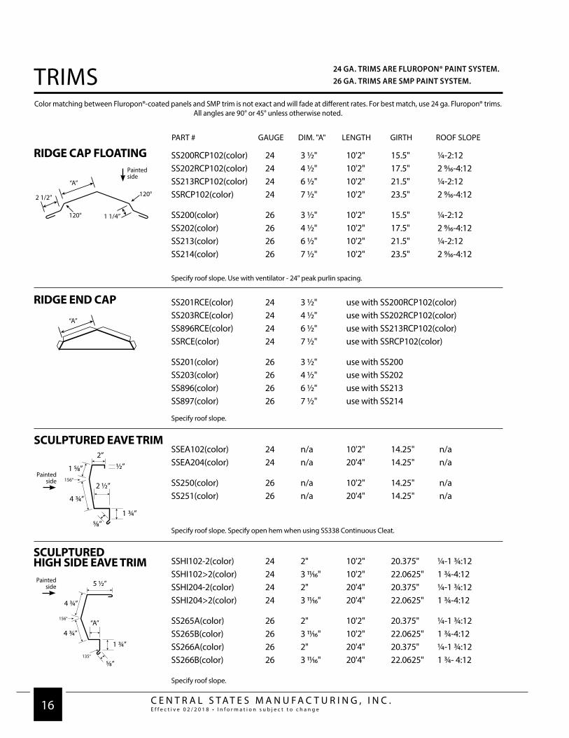
PART # GAUGE DIM. "A" LENGTH GIRTH ROOF SLOPE
RIDGE CAP FLOATING SS200RCP102(color) 24 3 1/2" 10'2" 15.5" 1/4-2:12SS202RCP102(color) 24 4 1/2" 10'2" 17.5" 2 9/16-4:12SS213RCP102(color) 24 6 1/2" 10'2" 21.5" 1/4-2:12SSRCP102(color) 24 7 1/2" 10'2" 23.5" 2 9/16-4:12
SS200(color) 26 3 1/2" 10'2" 15.5" 1/4-2:12SS202(color) 26 4 1/2" 10'2" 17.5" 2 9/16-4:12SS213(color) 26 6 1/2" 10'2" 21.5" 1/4-2:12SS214(color) 26 7 1/2" 10'2" 23.5" 2 9/16-4:12
2 1/2”
“A”
1 1/4”120°
120°
Painted side
Color matching between Fluropon®-coated panels and SMP trim is not exact and will fade at different rates. For best match, use 24 ga. Fluropon® trims. All angles are 90° or 45° unless otherwise noted.
RIDGE END CAP
“A”
SCULPTUREDHIGH SIDE EAVE TRIM SSHI102-2(color) 24 2" 10'2" 20.375" 1/4-1 3/4:12
SSHI102>2(color) 24 3 11/16" 10'2" 22.0625" 1 3/4-4:12SSHI204-2(color) 24 2" 20'4" 20.375" 1/4-1 3/4:12SSHI204>2(color) 24 3 11/16" 20'4" 22.0625" 1 3/4-4:12
SS265A(color) 26 2" 10'2" 20.375" 1/4-1 3/4:12SS265B(color) 26 3 11/16" 10'2" 22.0625" 1 3/4-4:12SS266A(color) 26 2" 20'4" 20.375" 1/4-1 3/4:12SS266B(color) 26 3 11/16" 20'4" 22.0625" 1 3/4- 4:12
“A”
Painted side
Specify roof slope. Use with ventilator - 24" peak purlin spacing.
SS201RCE(color) 24 3 1/2" use with SS200RCP102(color)SS203RCE(color) 24 4 1/2" use with SS202RCP102(color)SS896RCE(color) 24 6 1/2" use with SS213RCP102(color)SSRCE(color) 24 7 1/2" use with SSRCP102(color)
SS201(color) 26 3 1/2" use with SS200SS203(color) 26 4 1/2" use with SS202SS896(color) 26 6 1/2" use with SS213SS897(color) 26 7 1/2" use with SS214
Specify roof slope.
SCULPTURED EAVE TRIMSSEA102(color) 24 n/a 10'2" 14.25" n/aSSEA204(color) 24 n/a 20'4" 14.25" n/a
SS250(color) 26 n/a 10'2" 14.25" n/aSS251(color) 26 n/a 20'4" 14.25" n/a
Painted side
Specify roof slope. Specify open hem when using SS338 Continuous Cleat.
Specify roof slope.
24 GA. TRIMS ARE FLUROPON® PAINT SYSTEM.26 GA. TRIMS ARE SMP PAINT SYSTEM.TRIMS

C E N T R A L S T A T E S M A N U F A C T U R I N G , I N C .E f f e c t i v e 0 2 / 2 0 1 8 • I n f o r m a t i o n s u b j e c t t o c h a n g e 17
4”
1”
“A”
PART # GAUGE DIM. "A" LENGTH GIRTH ROOF SLOPE
SSRA102(color) 24 n/a 10'2" 19.25" n/aSSRA204(color) 24 n/a 20'4" 19.25" n/a
SS110(color) 26 n/a 10'2" 19.25" n/aSS111(color) 26 n/a 20'4" 19.25" n/a
SCULPTURED RAKE
Painted side
RAKE SLIDESSRS102(color) 24 n/a 10'2" 3" n/a
SS115(color) 26 n/a 10'2" 3" n/aPainted side
Color matching between Fluropon®-coated panels and SMP trim is not exact and will fade at different rates. For best match, use 24 ga. Fluropon® trims. All angles are 90° or 45° unless otherwise noted.
SS275EF102(color) 24 3.5" 10'2" 12.5" specify pitchSSEF102(color) 24 4.5" 10'2" 13.5" specify pitch
SS275 26 3.5" 10'2" 12.5" specify pitchSS274 26 4.5" 10'2" 13.5" specify pitch
Painted side4 ¾”
A”1 ¼”
2 ½”
135°
Specify pitch
PARAPET HIGH SIDEEAVE FLASH - FLOATING
SS285SF102(color) 24 3" 10'2" 8" n/aSSSF102(color) 24 5" 10'2" 10" n/aSSPRF102(color) 24 7" 10'2" 12" n/a
SS285 26 3" 10'2" 8" n/aSS286 26 5" 10'2" 10" n/aSS287 26 7" 10'2" 12" n/a
PARAPET RAKE FLASH
¾”
1” SSPRC102(color) 24 .75" 10'2" 2.25" n/a
SS290(color) 26 .75" 10'2" 2.25" n/a
PARAPET RAKE CLEAT
Painted side
Painted side
24 GA. TRIMS ARE FLUROPON® PAINT SYSTEM.26 GA. TRIMS ARE SMP PAINT SYSTEM. TRIMS

C E N T R A L S T A T E S M A N U F A C T U R I N G , I N C .E f f e c t i v e 0 2 / 2 0 1 8 • I n f o r m a t i o n s u b j e c t t o c h a n g e 18
PART # GAUGE DIM. "A" LENGTH GIRTH ROOF SLOPE
LOW VALLEY SSVAL102(color) 24 n/a 10'2" 38" n/aSSVAL204(color) 24 n/a 20'4" 38" n/a
SS700(color) 26 n/a 10'2" 38" n/aSS702(color) 26 n/a 20'4" 38" n/a
Color matching between Fluropon®-coated panels and SMP trim is not exact and will fade at different rates. For best match, use 24 ga. Fluropon® trims. All angles are 90° or 45° unless otherwise noted.
Specify roof slope.
HIGH VALLEYSSHVAL102(color) 24 n/a 10'2" 41.5" n/aSSHVAL204(color) 24 n/a 20'4" 41.5" n/a
SS712(color) 26 n/a 10'2" 41.5" n/aSS713(color) 26 n/a 20'4" 41.5" n/aSpecify roof slope.
ZEE CLOSURESSZEE102(color) 24 n/a 10'2" 5" n/a
SS360(color) 26 n/a 10'2" 5" n/aPainted
side
Use at hip conditions.
CONTINUOUS CLEATSSCC102(color) 24 n/a 10'2" 3" n/a
SS338(color) 26 n/a 10'2" 3" n/a
VARIABLE TERMINATION SSVT102(color) 24 n/a 10'2" 10.25" n/a
SS117(color) 26 n/a 14'2" 10.25" n/aPainted side
1”
3”
1”
9”
¾”90°
45°
3”16”
½”
2 ½”
135°
Painted side
Painted side
Painted side
24 GA. TRIMS ARE FLUROPON® PAINT SYSTEM.26 GA. TRIMS ARE SMP PAINT SYSTEM.TRIMS

C E N T R A L S T A T E S M A N U F A C T U R I N G , I N C .E f f e c t i v e 0 2 / 2 0 1 8 • I n f o r m a t i o n s u b j e c t t o c h a n g e 19
PART # GAUGE DIM. "A" LENGTH GIRTH ROOF SLOPE
SSPC102(color) 24 n/a 10'2" 8.5" n/a
SS272(color) 26 n/a 10'2" 8.5" n/a
BOX PANEL CAP TRIM
Color matching between Fluropon®-coated panels and SMP trim is not exact and will fade at different rates. For best match, use 24 ga. Fluropon® trims. All angles are 90° or 45° unless otherwise noted.
SSOPC102(color) 24 n/a 10'2" 7.5" n/a
SS271(color) 26 n/a 10'2" 7.5" n/a
OFFSET PANEL CAP TRIM
Painted side
SSCF102(color) 24 n/a 10'2" 4.5" n/a
SS341(color) 26 n/a 10'2" 4.5" n/a
COUNTERFLASH
Painted side
SSACF102(color) 24 n/a 10'2" 4.5" n/a
SS343(color) 26 n/a 10'2" 4.5" n/a
ALTERNATIVECOUNTERFLASH
Painted side
½”30°
90°2 ½”
1”
Specify roof slope.
Specify roof slope.
Specify roof slope.
FLAT SHEETFSK102(color) 24 10'2" 48.5"
Painted side
Additional pallet charge on orders of 10 or more.Order quantity under 10 sheet may be packaged in a roll.
24 GA. TRIMS ARE FLUROPON® PAINT SYSTEM.26 GA. TRIMS ARE SMP PAINT SYSTEM. TRIMS

C E N T R A L S T A T E S M A N U F A C T U R I N G , I N C .E f f e c t i v e 0 2 / 2 0 1 8 • I n f o r m a t i o n s u b j e c t t o c h a n g e 20
PART # GAUGE DIM. "A" LENGTH GIRTH ROOF SLOPE
FIXED PEAK BOXSSFXPB(color) 24 n/a 1'6" 21" 1/2-6:12SS121FXPB(color) 24 n/a 2'6" 21" 1/2-3 3/4:12
SS120(color) 26 n/a 1'6" 21" 1/2-6:12SS121(color) 26 n/a 2'6" 21" 1/2-3 3/4:12
Color matching between Fluropon®-coated panels and SMP trim is not exact and will fade at different rates. For best match, use 24 ga. Fluropon® trims. All angles are 90° or 45° unless otherwise noted.
Specify roof slope. Use with Central-Loc roof system. Use with SS110 or SS111 sculptured rake trim.
FLOATING PEAK BOX
SCULPTUREDRAKE END SSRE(color) 24 n/a n/a n/a n/a
SS134(color) 26 n/a n/a n/a n/a
Use with SS110 sculptured rake trim. Specify left or right.
OUTSIDE CORNER BOXSSOCB(color) 24 n/a 18" 16" n/a
SS230(color) 26 n/a 18" 16" n/a
SSPB102(color) 24 n/a 2'1" 33.5" 1/4-6:12SS126PB(color) 24 n/a 2'6" 37.25" 1/4-6:12
SS125(color) 26 n/a 2'1" 33.5" 1/4-6:12SS126(color) 26 n/a 2'6" 37.25" 1/4-6:12
Specify roof slope. Kit includes cinch angles and flexible membrane.Use with SS110 or SS111 sculptured rake trim. Check with sales representative for lead times.
Specify roof slope.
Painted side
Painted side
INSIDE CORNER BOXSSICB(color) 24
SS231(color) 26Specify roof slope.
24 GA. TRIMS ARE FLUROPON® PAINT SYSTEM.26 GA. TRIMS ARE SMP PAINT SYSTEM.TRIMS

C E N T R A L S T A T E S M A N U F A C T U R I N G , I N C .E f f e c t i v e 0 2 / 2 0 1 8 • I n f o r m a t i o n s u b j e c t t o c h a n g e 21
CSLDSE45(color) 24
DSE45(color) 26DSE90(color) 26
DOWNSPOUT ELBOW
DSOUTLET(color) 26DOWNSPOUT OUTLET
31/2"
2"41/4"
1/2" turn downs
CSLDSLVE(color) 24
DSLVE(color) 26
DOWNSPOUTCONNECTOR
CSLDSS(color) 24
DSS2(color) 26
DOWNSPOUT STRAP
Painted side
Painted side
Painted side
CL246 24GUTTER STRAPSSGEN(color) 24
SS245(color) 26
GUTTER END CAP
specify roof slope.
Left and right.
specify pitch.
10”
PART # GAUGE LENGTH GIRTH ROOF SLOPE
SSGU102(color) 24 10'2" 23 13/16" 1/4-4:12SSGU204(color) 24 20'4" 23 13/16" 1/4-4:12
SS240A(color) 26 10'2" 23 13/16" 1/4-4:12SS241A(color) 26 20'4" 23 13/16" 1/4-4:12
SCULPTURED GUTTER
Painted side
6
Specify roof slope.Use in installations where eave plates are not used.
CSLDS102(color) 24 10'2"CSLDS122(color) 24 12'2" CSLDS142(color) 24 14'2"CSLDS162(color) 24 16'2"CSLDS182(color) 24 18'2"CSLDS204(color) 24 20'4"
DS102(color) 26 10'2"DS122(color) 26 12'2" DS142(color) 26 14'2"DS162(color) 26 16'2"DS182(color) 26 18'2"DS204(color) 26 20'4"
DOWNSPOUT W/O KICKOUT
Painted side
DOWNSPOUT WITH KICKOUT
Painted side
GIRTH 16"
PART # GAUGE LENGTH PART # GAUGE LENGTH
CSLDK102(color) 24 10'2"CSLDK122(color) 24 12'2"CSLDK142(color) 24 14'2"CSLDK162(color) 24 16'2"CSLDK182(color) 24 18'2"CSLDK204(color) 24 20'4"
DK102(color) 26 10'2"DK122(color) 26 12'2" DK142(color) 26 14'2"DK162(color) 26 16'2"DK182(color) 26 18'2"DK204(color) 26 20'4"
Color matching between Fluropon®-coated panels and SMP trim is not exact and will fade at different rates. For best match, use 24 ga. Fluropon® trims. All angles are 90° or 45° unless otherwise noted.
Painted side
Painted side
24 GA. TRIMS ARE FLUROPON® PAINT SYSTEM.26 GA. TRIMS ARE SMP PAINT SYSTEM. GUTTERS

C E N T R A L S T A T E S M A N U F A C T U R I N G , I N C .E f f e c t i v e 0 2 / 2 0 1 8 • I n f o r m a t i o n s u b j e c t t o c h a n g e 22
PART # FINISH GAUGE SIZE LENGTH WEIGHT
CL7600 Red Oxide 14 1 1/2" x 3/8" x 1 1/2" 8'0" 7.75 lbs.
EAVE PLATE - LOW
*Longer lead times may apply.
optional - use with low clips
CL7616 Red Oxide 14 1 1/2" x 1" x 1 1/2" 8'0" 7.75 lbs.
EAVE PLATE - HIGH
Mandatory - use with high clips.
CL7617 Red Oxide 14 1 1/2" x 3/8" x 4 1/2" 8'0" 13.65 lbs.
FLOATINGEAVE PLATE - LOW
Use at eave when attaching panels to substructure at mid-point.Use with 8 x 5 x 5 Eave Strut.
CL7618* Red Oxide 14 1 1/2" x 1" x 5 7/16" 8'0" 15.62 lbs.
FLOATINGEAVE PLATE - HIGH
Use at eave when attaching panels to substructure at mid-point.Use with 8 x 5 x 5 Eave Strut.
1 1/2”
1 1/2”1”
3/8”
1 ½”
1”
1 ½”
EAVE PLATES
C E N T R A L S T A T E S M A N U F A C T U R I N G , I N C .E f f e c t i v e 0 2 / 2 0 1 8 • I n f o r m a t i o n s u b j e c t t o c h a n g e 23
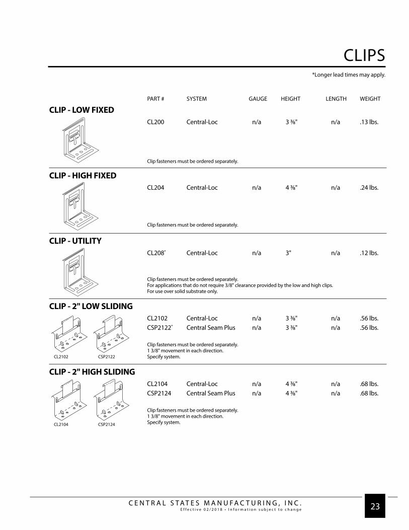
PART # SYSTEM GAUGE HEIGHT LENGTH WEIGHT
CL200 Central-Loc n/a 3 3/8" n/a .13 lbs.
CLIP - LOW FIXED
Clip fasteners must be ordered separately.
CL204 Central-Loc n/a 4 3/8" n/a .24 lbs.
CLIP - HIGH FIXED
Clip fasteners must be ordered separately.
CL208* Central-Loc n/a 3" n/a .12 lbs.
CLIP - UTILITY
Clip fasteners must be ordered separately.For applications that do not require 3/8" clearance provided by the low and high clips.For use over solid substrate only.
CL2102 Central-Loc n/a 3 3/8" n/a .56 lbs.CSP2122* Central Seam Plus n/a 3 3/8" n/a .56 lbs.
CLIP - 2" LOW SLIDING
Clip fasteners must be ordered separately.1 3/8" movement in each direction.Specify system.
CL2104 Central-Loc n/a 4 3/8" n/a .68 lbs.CSP2124 Central Seam Plus n/a 4 3/8" n/a .68 lbs.
CLIP - 2" HIGH SLIDING
Clip fasteners must be ordered separately.1 3/8" movement in each direction.Specify system.
CL2102 CSP2122
CL2104 CSP2124
*Longer lead times may apply.
CLIPS
C E N T R A L S T A T E S M A N U F A C T U R I N G , I N C .E f f e c t i v e 0 2 / 2 0 1 8 • I n f o r m a t i o n s u b j e c t t o c h a n g e 24
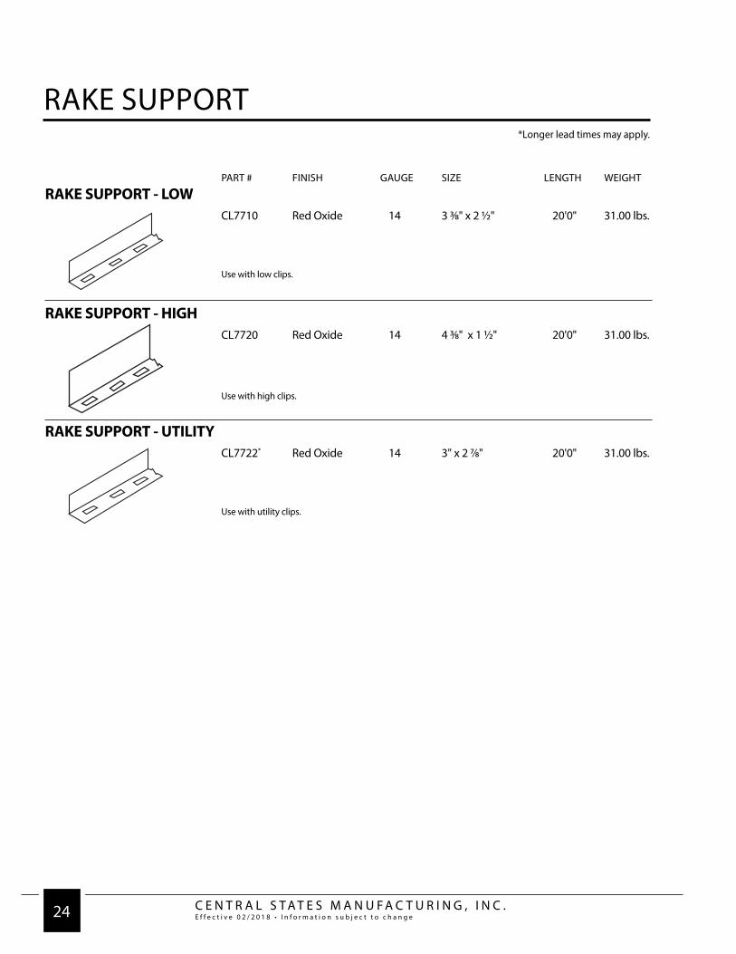
PART # FINISH GAUGE SIZE LENGTH WEIGHT
*Longer lead times may apply.
CL7710 Red Oxide 14 3 3/8" x 2 1/2" 20'0" 31.00 lbs.
RAKE SUPPORT - LOW
Use with low clips.
CL7720 Red Oxide 14 4 3/8" x 1 1/2" 20'0" 31.00 lbs.
RAKE SUPPORT - HIGH
Use with high clips.
CL7722* Red Oxide 14 3" x 2 7/8" 20'0" 31.00 lbs.
RAKE SUPPORT - UTILITY
Use with utility clips.
RAKE SUPPORT
C E N T R A L S T A T E S M A N U F A C T U R I N G , I N C .E f f e c t i v e 0 2 / 2 0 1 8 • I n f o r m a t i o n s u b j e c t t o c h a n g e 25
PART # FINISH GAUGE SIZE LENGTH WEIGHT
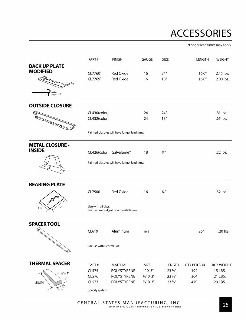
CL7760* Red Oxide 16 24" 16'0" 2.45 lbs.CL7769* Red Oxide 16 18" 16'0" 2.00 lbs.
BACK UP PLATEMODIFIED
*Longer lead times may apply.
CL430(color) 24 24" .81 lbs.CL432(color) 24 18" .65 lbs.
OUTSIDE CLOSURE
Painted closures will have longer lead time.
CL426(color) Galvalume® 18 3/4" .22 lbs.
METAL CLOSURE -INSIDE
CL7500 Red Oxide 16 3/4" .32 lbs.
BEARING PLATE
Use with all clips.For use over ridged board installation.
CL619 Aluminum n/a 26" .20 lbs.
SPACER TOOL
For use with Central-Loc
CL575 POLYSTYRENE 1" X 3" 23 7/8" 192 15 LBS.CL576 POLYSTYRENE 5/8" X 3" 23 7/8" 304 21 LBS.CL577 POLYSTYRENE 3/8" X 3" 23 7/8" 479 29 LBS.
THERMAL SPACER
Specify system
1/8”
3 7⁄8” 5”
PART # MATERIAL SIZE LENGTH QTY PER BOX BOX WEIGHT
Painted closures will have longer lead time.
ACCESSORIES

C E N T R A L S T A T E S M A N U F A C T U R I N G , I N C .E f f e c t i v e 0 2 / 2 0 1 8 • I n f o r m a t i o n s u b j e c t t o c h a n g e 26
• Clip to purlin with up to 4" insulation thickness.• Eave plate to eave strut.
• Inside closure to eave plate or eave strut.• Rake support to purlin (fixed system only).
PART # HEAD SIZE TYPE #PER BAG
FASTENER #11FASTENER 5/16" Driller 2501/4" - 14 X 1" Driller
5/16" Hex Washer Head w/ 5/8" O.D. Washer
FASTENER #1E1EFASTENER 5/16" Long Life Driller 2501/4" - 14 X 11/4" Long life driller
5/16" Hex Washer Head w/Sealing Washer• Panel to eave plate or eave strut.• Rake trim to roof panel.
• Outside Closure• Endlap
FASTENER #1F1FFASTENER 5/16" Driller 2501/4" - 14 X 11/2" Driller
5/16" Hex Washer Head w/ 5/8" O.D. Washer• Clip to purlin with up to 4" insulation thickness.
FASTENER #44FASTENER* 5/16" Long Life Lap TEK 2501/4" - 14 X 7/8" Long life lap TEK
5/16" Hex Washer Head w/Sealing Washer• Ridge and other flashing to outside closure.• Gutter to panel.
• Gutter to strap.• Trim to trim connections.
FASTENER #77FASTENER* 5/16" Shoulder TEK 2501/4" - 20 X 11/4" Shoulder TEK 4
5/16" Hex Washer Head•Rake support to bar joist.• Floating eave plate to bar joist.
• Rake support to purlin.• Floating eave plate to eave strut.
FASTENER #55FASTENER* 5/16" Shoulder TEK 2501/4" - 14 X 11/4" Shoulder TEK
5/16" Hex Washer Head
ACCESSORIES

C E N T R A L S T A T E S M A N U F A C T U R I N G , I N C .E f f e c t i v e 0 2 / 2 0 1 8 • I n f o r m a t i o n s u b j e c t t o c h a n g e 27
PART # HEAD SIZE TYPE #PER BAG
FASTENER #1414FASTENER n/a Pop Rivet 1001/8" x 0.337": Pop Rivet
Stainless steel• Gutter strap to snow gutter.
FASTENER #14A14AFASTENER n/a Pop Rivet 1001/8" x 0.525": Pop Rivet
Stainless steel• Snow gutter to eave plate.• Outside closure to back-up angle at hip condition.
FASTENER #1212FASTENER 2/2" Driller 2502/2" Quadrex Driller
• Support plate to purlins at valley and hip conditions.• Rake angle to purlins.
POP RIVET POP(color) 3/16" Pop Rivet 100FOR FLASHING JOINTS
PART # TYPE WIDTH THICKNESS LENGTH #PER CARTON CARTON WT.TAPE SEALER
CL512A Minor Rib 1 3/8" 7/32" 4" 144pc. 10.0 lbs CL502A Triple Bead 2 1/2" 3/16" 20' 6 rolls 23.0 lbs CL504A Tri-Bead 7/8" 3/16" 26' 8 rolls 20.0 lbs
Use to fill any voids at the minor ribs of panel for eave and valley conditions.Sold by carton only.
PART # TYPE COLOR TUBE SIZE #PER CARTON CARTON WT.GEOC Tripolymer Clear 10.3 oz. 24 .85 lbsGEOG Tripolymer Gray 10.3 oz. 24 .85 lbsGEOW Tripolymer White 10.3 oz. 24 .85 lbs MRS(color) call for colors 10.3 oz.MRSCLEAR clear 10.3 oz.
SEALANT
CL502A
CL504A
CL512A
ACCESSORIES

w w w.CentralStatesMfg.com