centrifugal advance - mgb-stuff.org.uk · centrifugal advance ... turned anti -clockwise relative...
TRANSCRIPT
Centrifugal Advance
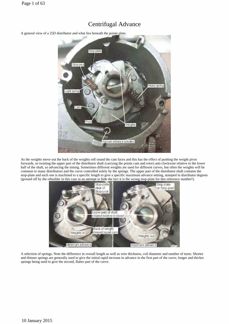
A general view of a 25D distributor and what lies beneath the points plate.
As the weights move out the back of the weights roll round the cam faces and this has the effect of pushing the weight pivot forwards, so twisting the upper part of the distributor shaft (carrying the points cam and rotor) anti-clockwise relative to the lower half of the shaft, so advancing the timing. Sometimes different weights are used for different curves, but often the weights will be common to many distributors and the curve controlled solely by the springs. The upper part of the distributor shaft contains the stop-plate and each one is machined to a specific length to give a specific maximum advance setting, stamped in distributor degrees (ground off by the rebuilder in this case in an attempt to hide the fact it is the wrong stop-plate for this reference number!).
A selection of springs. Note the difference in overall length as well as wire thickness, coil diameter and number of turns. Shorter and thinner springs are generally used to give the initial rapid increase in advance in the first part of the curve, longer and thicker springs being used to give the second, flatter part of the curve.
Page 1 of 63
10 January 2015

A general view of what lies under a typical 45D points plate, this distributor has had part of the body cut away for test purposes. This shows a 10 (distributor) degree maximum advance stop-plate, the stamping being a bit close to the edge. The 45D centrifugal advance mechanism takes up less space than the 25D, so the body of the distributor can be smaller. This makes it slightly easier to remove the distributor complete with clamping plate, which means on re-insertion the timing is usually close enough to get the engine started and perform dynamic timing rather than static time first before it can be started. It also avoids re-tightening the clamp-plate bolt, which most people over-tighten, which can damage the shoulder of the distributor and cause it to jump out of engagement.
Maximum centrifugal advance, stop-plate against stop-peg.
Page 2 of 63
10 January 2015

The next bit shows the upper part of the shaft having been removed from the distributor. To just get at the springs this isn't required, but if you do decide to remove it, a warning: Unlike the 25D which has a screw holding the upper half of the shaft to the lower (on the left in this picture), the 45D has just a plastic lock-ring sitting in a groove in the top of the lower shaft (on the right). On the 45D the two have to be forced apart, which can damage the lock-ring. Don't be tempted to re-install the distributor to an engine without some means of securing the upper and lower shafts back together or you could destroy the distributor if the upper half of the shaft jumps up. A stack of washers (to take up some of the space the lock-ring occupied) and a circlip of a suitable size should be OK.
The bare bones of the lower half of the shaft.
Page 3 of 63
10 January 2015
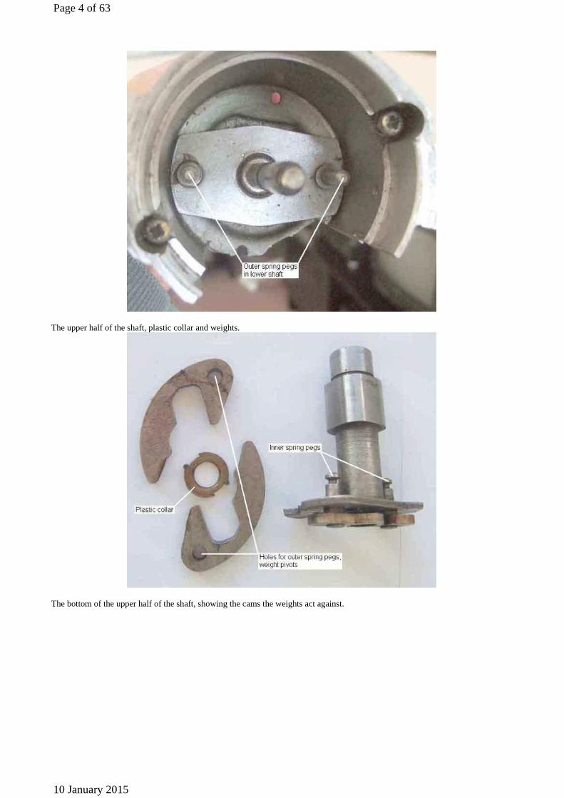
The upper half of the shaft, plastic collar and weights.
The bottom of the upper half of the shaft, showing the cams the weights act against.
Page 4 of 63
10 January 2015
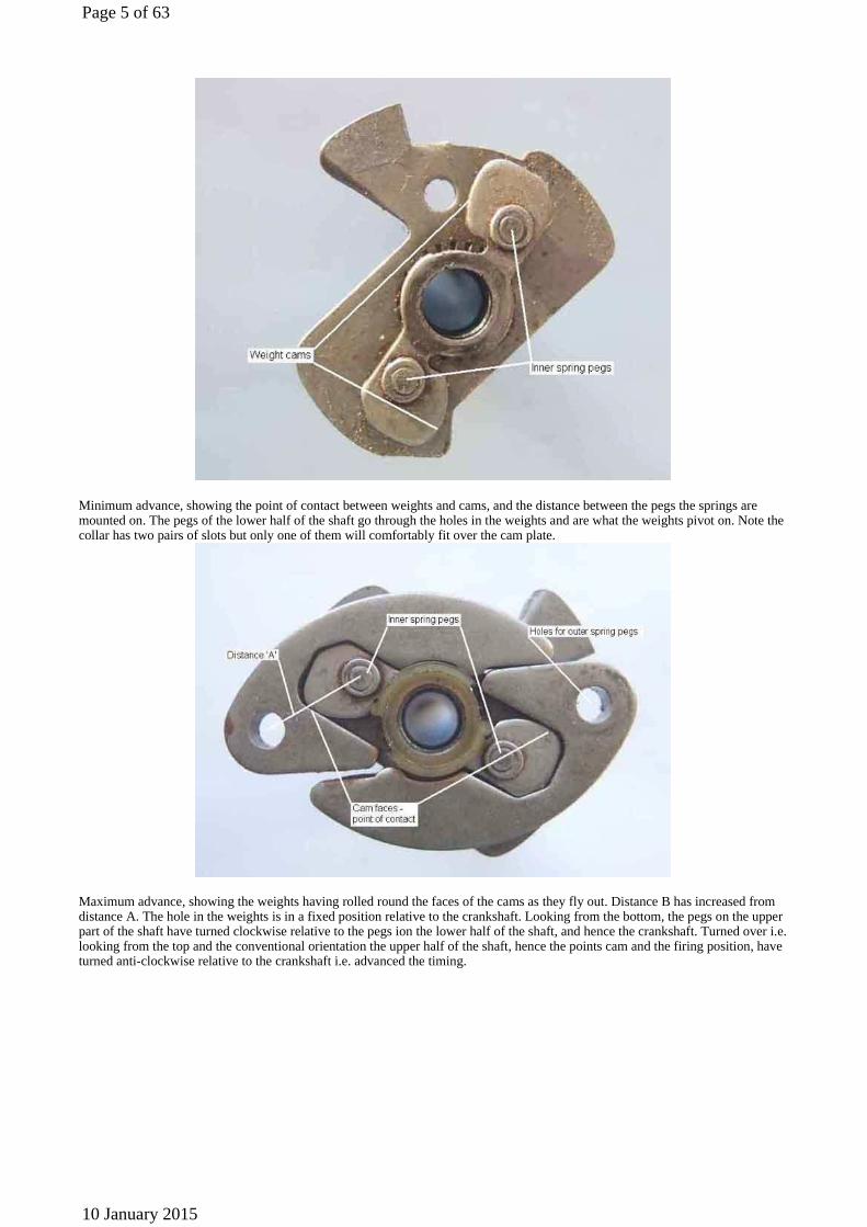
Minimum advance, showing the point of contact between weights and cams, and the distance between the pegs the springs are mounted on. The pegs of the lower half of the shaft go through the holes in the weights and are what the weights pivot on. Note the collar has two pairs of slots but only one of them will comfortably fit over the cam plate.
Maximum advance, showing the weights having rolled round the faces of the cams as they fly out. Distance B has increased from distance A. The hole in the weights is in a fixed position relative to the crankshaft. Looking from the bottom, the pegs on the upper part of the shaft have turned clockwise relative to the pegs ion the lower half of the shaft, and hence the crankshaft. Turned over i.e. looking from the top and the conventional orientation the upper half of the shaft, hence the points cam and the firing position, have turned anti-clockwise relative to the crankshaft i.e. advanced the timing.
Page 5 of 63
10 January 2015

Tip: If you disassemble a 45D distributor as I have done, it is very tricky getting the upper half of the shaft and the plastic collar correctly located by putting them down into the distributor body. Hold the upper half of the shaft upside down, fit the weights and the collar to that as shown in the two pictures above, then lower the distributor body down onto that. The only thing you have to line up then is the pegs in the lower half of the shaft with the holes in the weights, which is much easier.
Condensers
Condenser as used in 4-cylinder 25D4 and V8 distributors ...
... and one for a 45D4 distributor incorporating the connector for the 'quick-fit' points and lead out towards the coil.
Page 6 of 63
10 January 2015
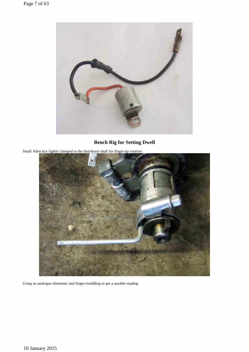
Bench Rig for Setting Dwell
Small Allen key lightly clamped to the distributor shaft for finger-tip rotation
Using an analogue ohmmeter and finger-twiddling to get a useable reading
Page 7 of 63
10 January 2015
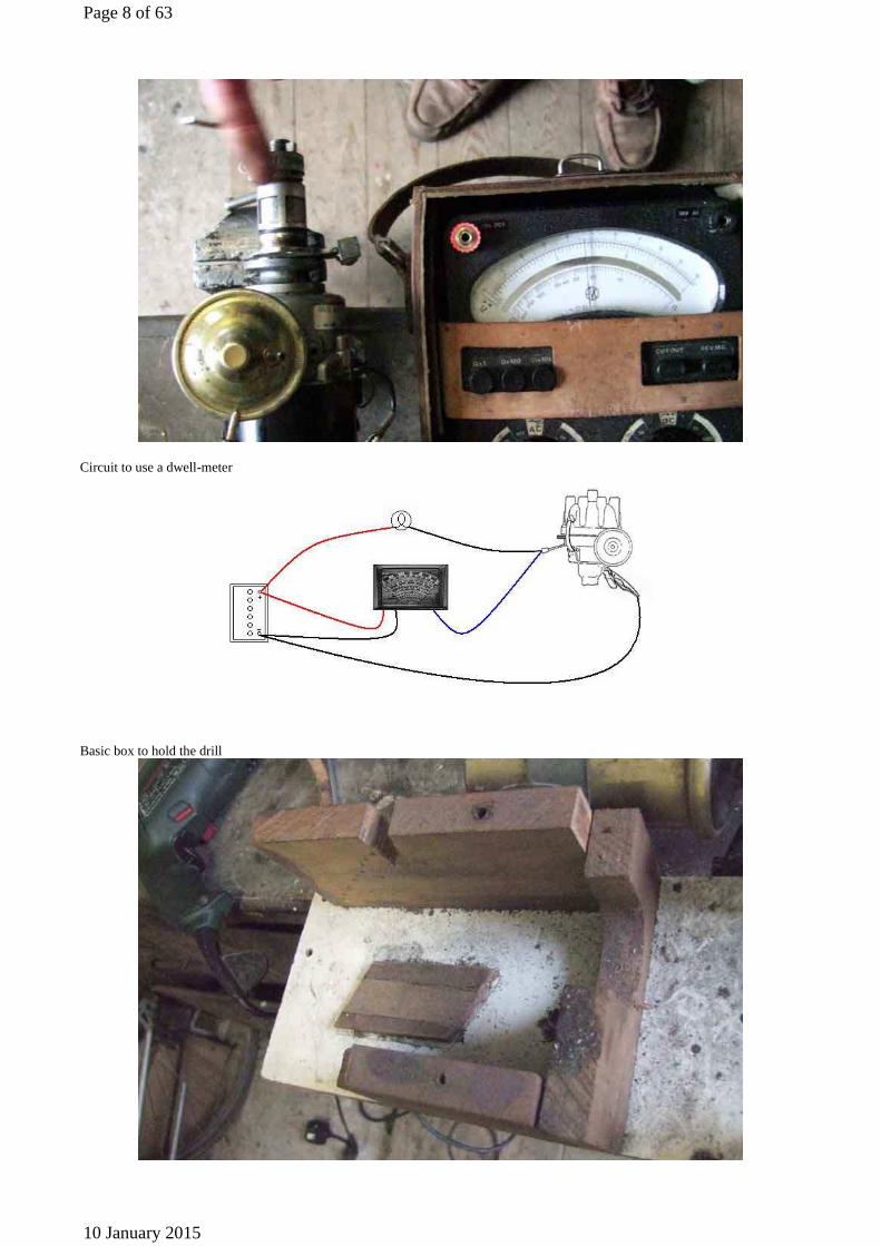
Circuit to use a dwell-meter
Basic box to hold the drill
Page 8 of 63
10 January 2015

Clamps to hold the drill steady (coil and plugs were so I could drive a strobe light to measure curves)
Distributor drive dog (the blue thing is a right-angle gearbox to drive a degree wheel for measuring curves)
Page 9 of 63
10 January 2015
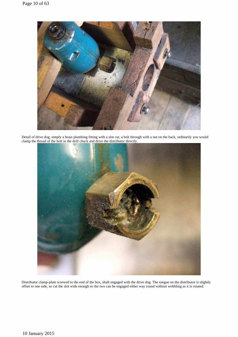
Detail of drive dog, simply a brass plumbing fitting with a slot cut, a bolt through with a nut on the back, ordinarily you would clamp the thread of the bolt in the drill chuck and drive the distributor directly.
Distributor clamp-plate screwed to the end of the box, shaft engaged with the drive dog. The tongue on the distributor is slightly offset to one side, so cut the slot wide enough so the two can be engaged either way round without wobbling as it is rotated.
Page 10 of 63
10 January 2015
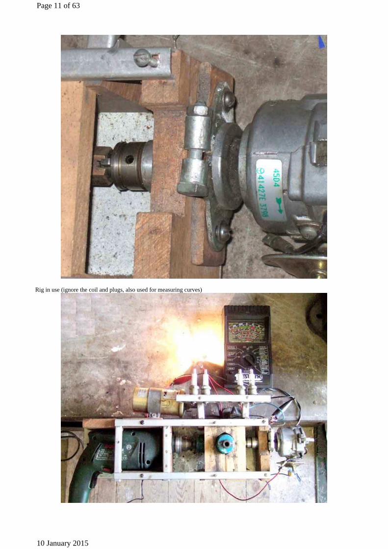
Rig in use (ignore the coil and plugs, also used for measuring curves)
Page 11 of 63
10 January 2015

Points Types
The 'fiddle fit' points for the 25D GCS101 (main image, 2-part GCS107 inset) consisting of several parts which must be assembled in the correct order or you will get ignition problems. Note: These can have white cam-followers from other manufacturers as well as the red from Lucas shown here.
First on the threaded stud is a stepped insulating washer, with the step facing upwards.
Next is the spring of the moving contact, located over the step in the washer.
Page 12 of 63
10 January 2015

Next go the condenser and the coil wire tags, in either order.
Next is the other stepped insulating washer, this time with the step facing downwards, so it goes through the holes in the condenser and coil wire tags and the spring of the moving contact.
Page 13 of 63
10 January 2015

Finally the nut. These seem to be 'handed' in that one side seems flat and the other side has slightly rounded edges to each flat of the hexagon. I always put the flat side against the upper insulating washer as it just seems more 'correct', but I don't suppose it is critical.
The steps in the insulating washers go inside the holes in the moving contact spring and the condenser and coil wire tags so as to prevent them coming into contact with the threaded stud and nut. These two components are at earth/ground potential, and if the coil wire comes into contact with either stud or nut - either because the washers are the wrong way round, not seated properly, or the tags are between the washer and nut - the points will be bypassed, the coil continually flowing current, and there will be no spark. Also be aware that if the points tag is correct but the condenser tag is fitted between the washer and nut you will have ignition, but very weak sparking and lots of points arcing as the condenser will be out of circuit.
Page 14 of 63
10 January 2015
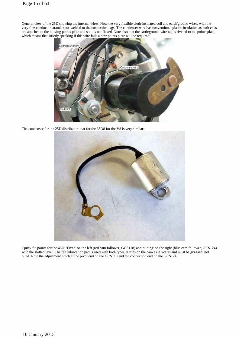
General view of the 25D showing the internal wires. Note the very flexible cloth-insulated coil and earth/ground wires, with the very fine conductor strands spot-welded to the connection tags. The condenser wire has conventional plastic insulation as both ends are attached to the moving points plate and so it is not flexed. Note also that the earth/ground wire tag is riveted to the points plate, which means that strictly speaking if this wire fails a new points plate will be required:
The condenser for the 25D distributor, that for the 35D8 for the V8 is very similar:
'Quick fit' points for the 45D: 'Fixed' on the left (red cam follower, GCS118) and 'sliding' on the right (blue cam follower, GCS124) with the slotted lever. The felt lubrication pad is used with both types, it rubs on the cam as it rotates and must be greased, not oiled. Note the adjustment notch at the pivot end on the GCS118 and the connection end on the GCS124.
Page 15 of 63
10 January 2015

With this type the moving contact spring just lays in a channel in a plastic insulator fixed to a post on the fixed contact base. The end of the spring has a partially flattened loop, and a flat brass connector with the condenser and coil wires already attached simply slides into the loop. The only important thing here is that the plastic insulator does lie between the post and the spring.
Showing the 45D 'sliding contact' type, with the points plate in the minimum vacuum advance position on the left and the maximum vacuum advance position on the right. Note the difference in angle of the slotted lever (circled):
Showing the 45D 'sliding contact' type, with the slotted lever in the minimum advance position (left) and maximum advance position (right). Note the difference in height of the cam follower and the different offset of the points in each case.
Page 16 of 63
10 January 2015
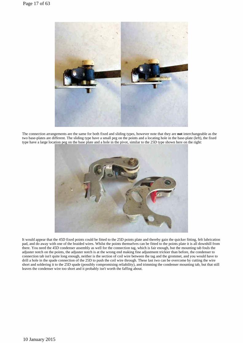
The connection arrangements are the same for both fixed and sliding types, however note that they are not interchangeable as the two base-plates are different. The sliding type have a small peg on the points and a locating hole in the base-plate (left), the fixed type have a large location peg on the base plate and a hole in the pivot, similar to the 25D type shown here on the right:
It would appear that the 45D fixed points could be fitted to the 25D points plate and thereby gain the quicker fitting, felt lubrication pad, and do away with one of the braided wires. Whilst the points themselves can be fitted to the points plate it is all downhill from there. You need the 45D condenser assembly as well for the connection tag, which is fair enough, but the mounting tab fouls the adjuster notch on the points, the adjuster notch is at the wrong end making fine adjustment trickier than before, the condenser to connection tab isn't quite long enough, neither is the section of coil wire between the tag and the grommet, and you would have to drill a hole in the spade connection of the 25D to push the coil wire through. These last two can be overcome by cutting the wire short and soldering it to the 25D spade (possibly compromising reliability), and trimming the condenser mounting tab, but that still leaves the condenser wire too short and it probably isn't worth the faffing about.
Page 17 of 63
10 January 2015

All types of points are secured with a screw, spring washer and plain washer. On an original distributor in my possession the screw is unusual in that it has a plain, narrower portion at the tip before the thread starts (shown on the left below). This aids insertion as you can drop it and the washers into the hole in the points, the plain tip drops into the threaded hole in the points plate, holding the screw upright and relatively secure while you get the screwdriver on it and start to tighten it. Replacement screws, and those in rebuilt distributors, seem to be standard screws threaded for their full length (on the right). With these you really have to drop the screw and washer onto the top of the points while they are out of the distributor, then move the points towards the points plate with one hand and a screwdriver in the other pressing gently down on the screw head. Before the points are lowered all the way to lie on the points plate start turning the screwdriver to start the screw, and then you can let the points go. If you let the points lie on the points plate before the screw has started it will topple over and there is a good chance the washers at least will fall into the centrifugal mechanism. Not too bad if the distributor is already removed as you can just up-end it, shake it, and hope to catch the bits as they fall out, but a nuisance if the distributor is still installed.
Both 25D and 45D have earth/ground springs between the moving points plate and the fixed base plate, which should mean that a separate earth/ground wire is not required. But having experienced intermittent cutting out when pressing the throttle on a Scimitar GTE - usually just when pulling out into traffic(!), with a Ford distributor that only had the sliding contact by design, I wouldn't recommend it. In fact the first Scimitar tip I came across was to retro-fit a ground wire, which I did, and it solved the problem. This is the 25D ...
Page 18 of 63
10 January 2015

... and this the 45D:
Cloth-insulated earth/ground wire for a 45D, screw tags at both ends, so can be replaced independently. This could be used as a replacement for the 25D as well, if obtainable:
Page 19 of 63
10 January 2015
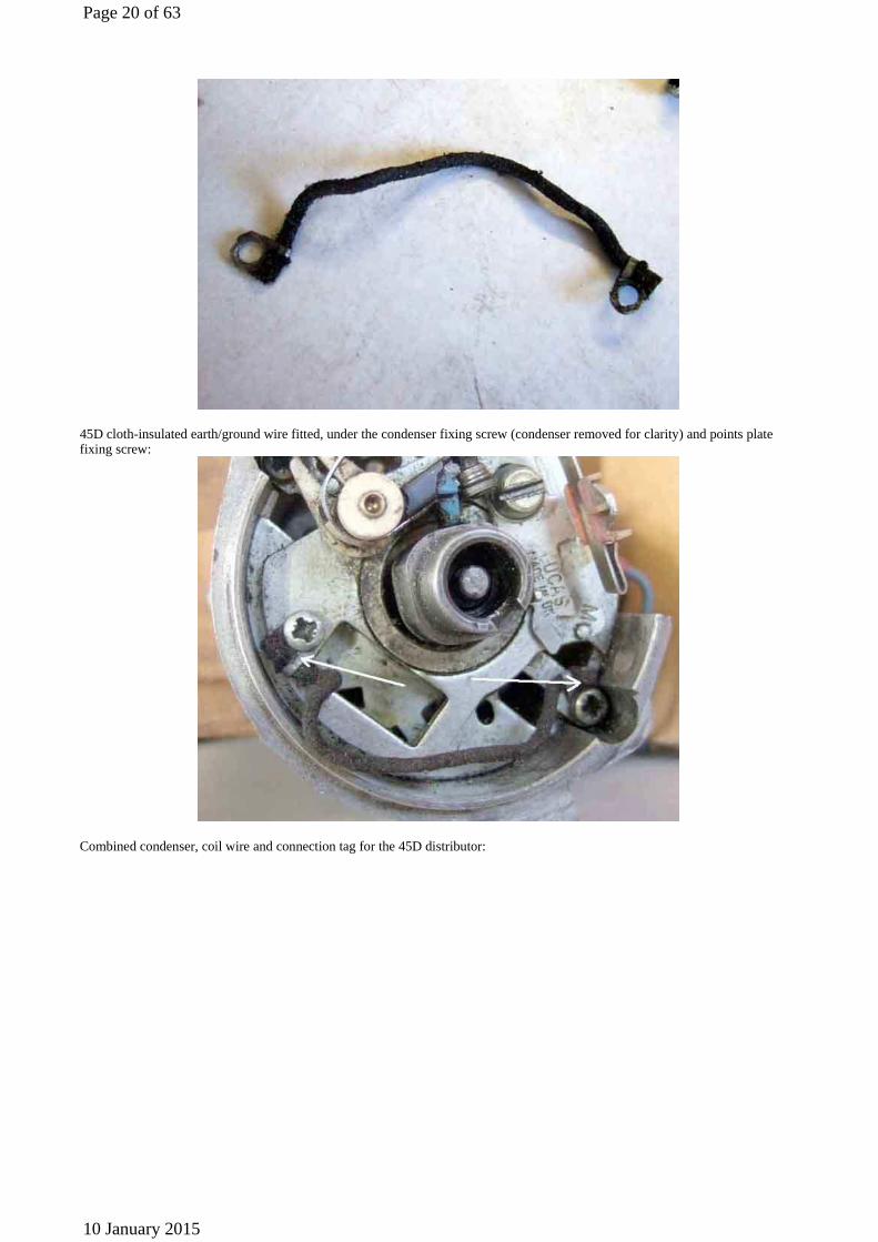
45D cloth-insulated earth/ground wire fitted, under the condenser fixing screw (condenser removed for clarity) and points plate fixing screw:
Combined condenser, coil wire and connection tag for the 45D distributor:
Page 20 of 63
10 January 2015

Fine adjustment V-notches of the 25D (circled). With the points screw only lightly tightened a screwdriver inserted in the notches can be twisted one way and the other to open or close the gap. Because the fixing screw is only lightly tightened, when the screwdriver is removed the gap remains the same, the screw can then be fully tightened, and the gap rechecked to make sure it hasn't shifted.
The fine adjustment 'V-notch and pip' (circled) of 45D sliding points (45D fixed points have the V-notch at the pivot end of the points plate):
Page 21 of 63
10 January 2015
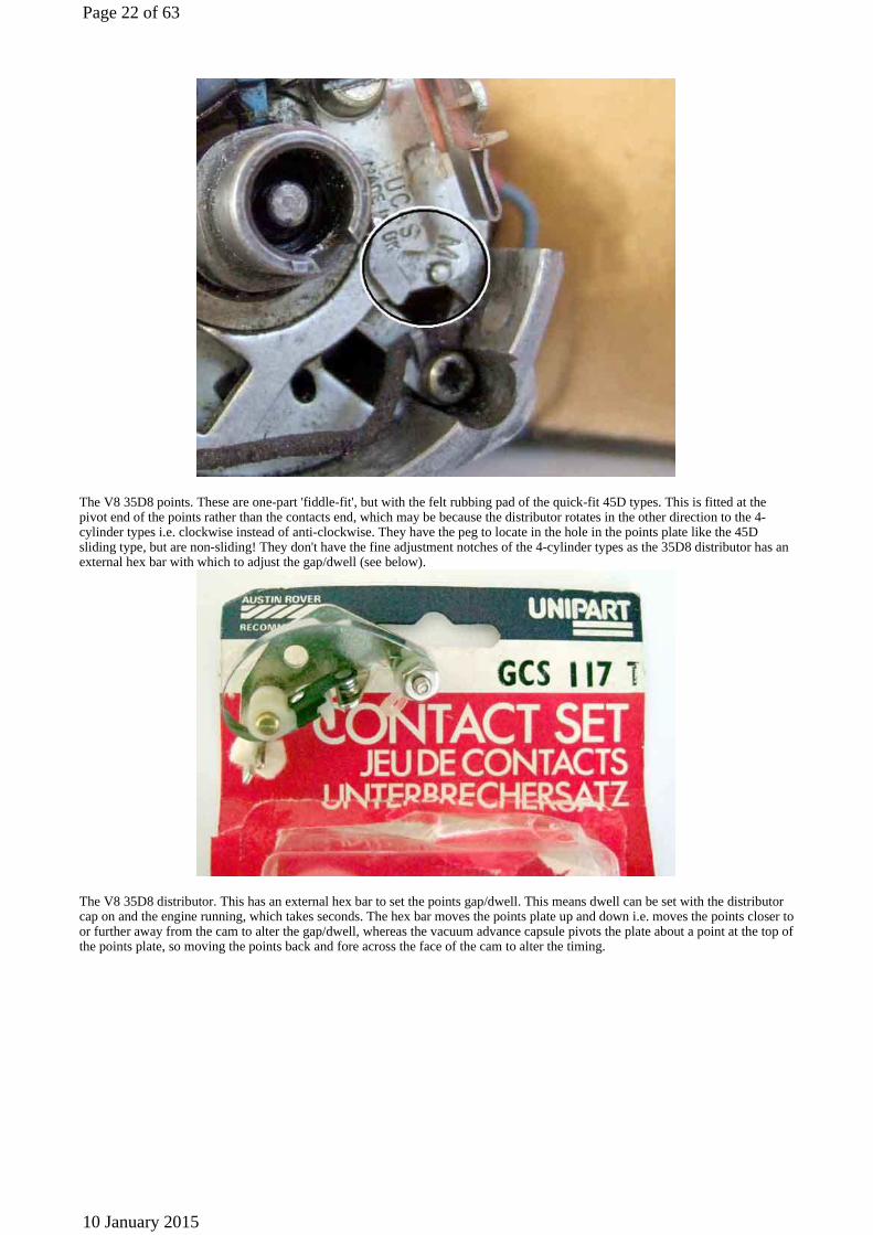
The V8 35D8 points. These are one-part 'fiddle-fit', but with the felt rubbing pad of the quick-fit 45D types. This is fitted at the pivot end of the points rather than the contacts end, which may be because the distributor rotates in the other direction to the 4-cylinder types i.e. clockwise instead of anti-clockwise. They have the peg to locate in the hole in the points plate like the 45D sliding type, but are non-sliding! They don't have the fine adjustment notches of the 4-cylinder types as the 35D8 distributor has an external hex bar with which to adjust the gap/dwell (see below).
The V8 35D8 distributor. This has an external hex bar to set the points gap/dwell. This means dwell can be set with the distributor cap on and the engine running, which takes seconds. The hex bar moves the points plate up and down i.e. moves the points closer to or further away from the cam to alter the gap/dwell, whereas the vacuum advance capsule pivots the plate about a point at the top of the points plate, so moving the points back and fore across the face of the cam to alter the timing.
Page 22 of 63
10 January 2015

Distributor Caps
A nearly new 45D4 cap with the carbon contact missing, and fragments of spring floating around inside, which has worn and burnt the (also nearly new) rotor. Subsequently the contact was found lying on the points plate.
Distributor Drive-dog Showing the drive-dog off-set from the centre-line
Page 23 of 63
10 January 2015
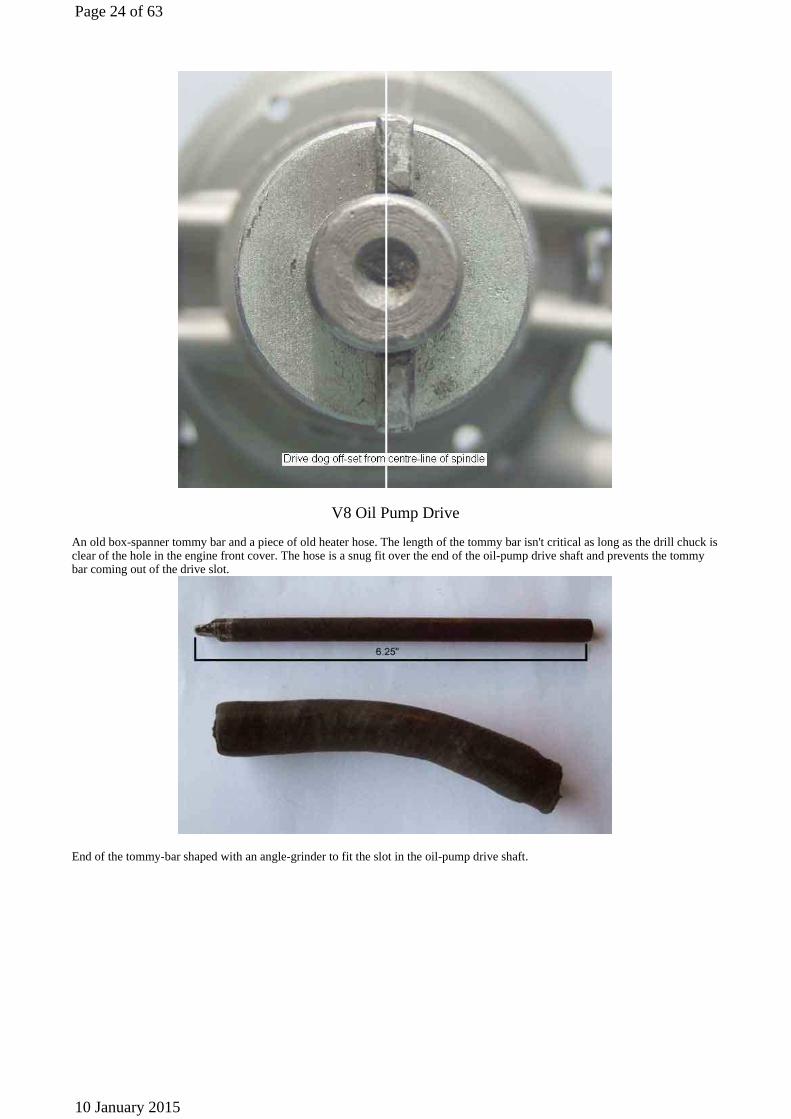
V8 Oil Pump Drive An old box-spanner tommy bar and a piece of old heater hose. The length of the tommy bar isn't critical as long as the drill chuck is clear of the hole in the engine front cover. The hose is a snug fit over the end of the oil-pump drive shaft and prevents the tommy bar coming out of the drive slot.
End of the tommy-bar shaped with an angle-grinder to fit the slot in the oil-pump drive shaft.
Page 24 of 63
10 January 2015
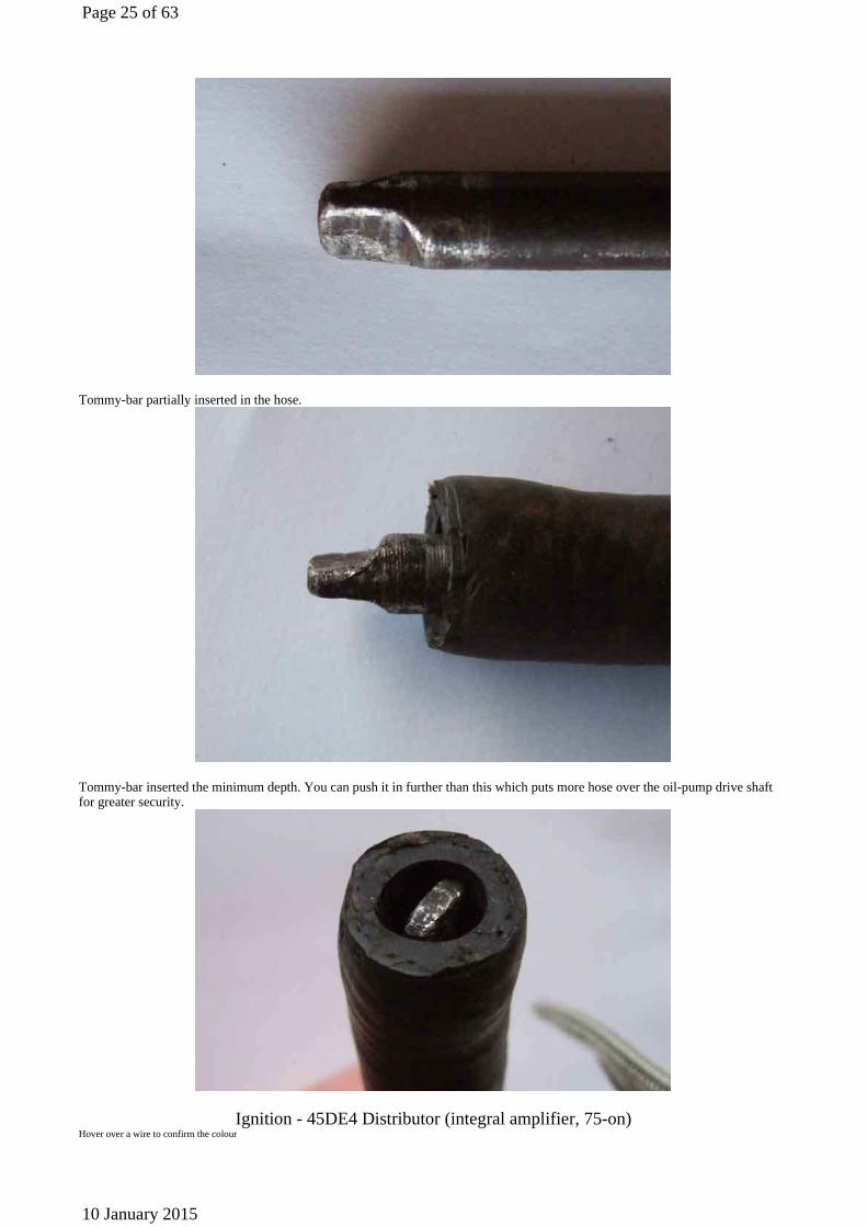
Tommy-bar partially inserted in the hose.
Tommy-bar inserted the minimum depth. You can push it in further than this which puts more hose over the oil-pump drive shaft for greater security.
Ignition - 45DE4 Distributor (integral amplifier, 75-on) Hover over a wire to confirm the colour
Page 25 of 63
10 January 2015
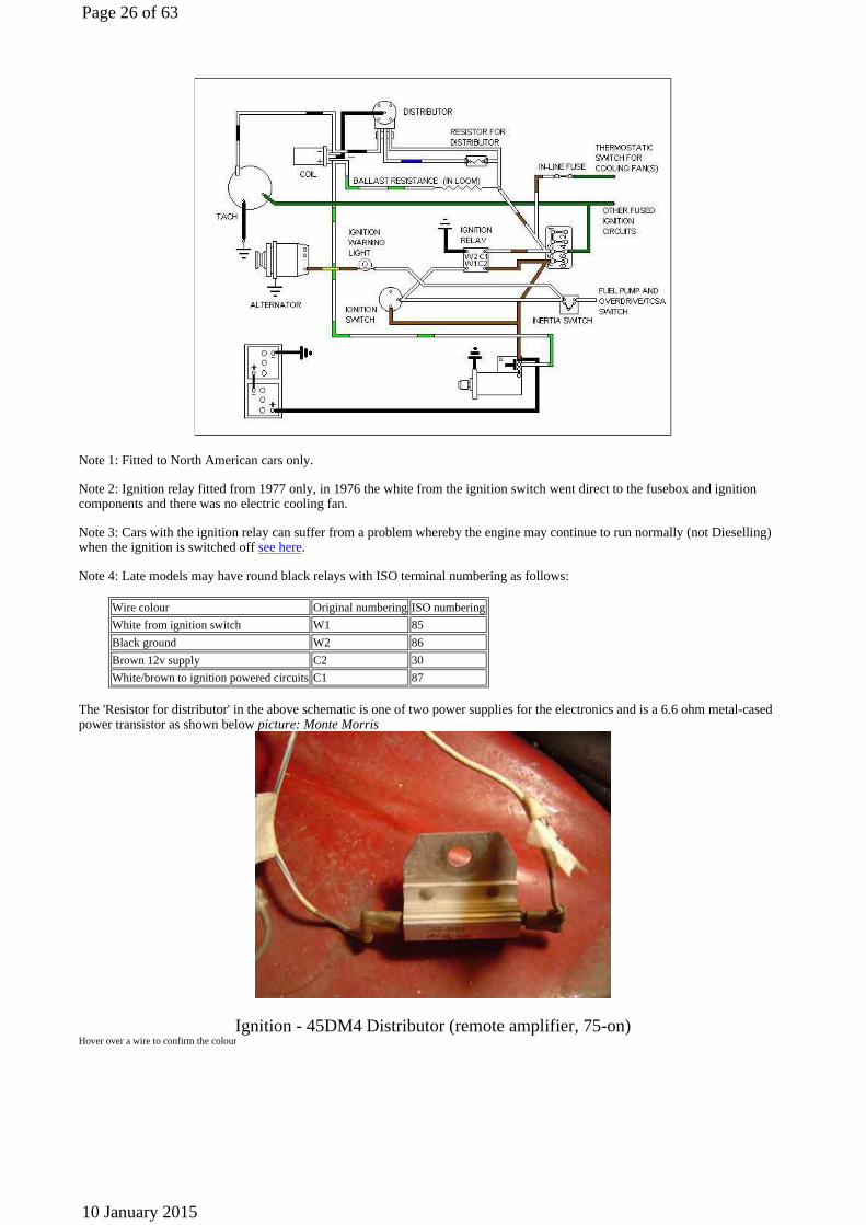
Note 1: Fitted to North American cars only.
Note 2: Ignition relay fitted from 1977 only, in 1976 the white from the ignition switch went direct to the fusebox and ignition components and there was no electric cooling fan.
Note 3: Cars with the ignition relay can suffer from a problem whereby the engine may continue to run normally (not Dieselling) when the ignition is switched off see here.
Note 4: Late models may have round black relays with ISO terminal numbering as follows:
The 'Resistor for distributor' in the above schematic is one of two power supplies for the electronics and is a 6.6 ohm metal-cased power transistor as shown below picture: Monte Morris
Ignition - 45DM4 Distributor (remote amplifier, 75-on) Hover over a wire to confirm the colour
Wire colour Original numberingISO numbering
White from ignition switch W1 85
Black ground W2 86
Brown 12v supply C2 30
White/brown to ignition powered circuitsC1 87
Page 26 of 63
10 January 2015

Note 1: Fitted to North American cars only.
Note 2: North American cars can suffer from a problem whereby the engine may continue to run normally (not Dieselling) when the ignition is switched off see here.
Note 3: Late models have round black relays with ISO terminal numbering as follows:
Electronic Triggers
The no-name trigger contained within a distributor purchased from eBay.
Wire colour Original numberingISO numbering
White from ignition switch W1 85
Black ground W2 86
Brown 12v supply C2 30
White/brown to ignition powered circuitsC1 87
Page 27 of 63
10 January 2015

Note the one-piece rotor and magnet ring, the magnets being in the wider ring at the base of the rotor (on the left, standard rotor on the right). This differs from other manufacturers who seem to supply just the magnetic ring with their triggers, a standard rotor going on the top. The complete thing was cheap at £50. Normally the triggers themselves are around £90 (Magnetronic and Aldon) although considerably cheaper from Pertronix at about £60, and with points distributors typically being about £80 new David didn't get a bad deal anyway even taking into account having to retro-fit points and a condenser.
Subsequently Gary Falkiner pointed me to this ETC5835k from various Land Rover specialists sold as a conversion kit using the original distributor. This image (from Britpart) looks pretty-much identical. Although this initially seemed to work OK it became inconsistent, and was picking up iron filings on the magnetic collar, so Gary has gone back to points as well.
Page 28 of 63
10 January 2015
Ignition Ballast
The pink/white resistance wire, measuring about 1.4 ohms, is in the centre.
There is a white/light-green tail on the left that goes to the coil positive and the starter solenoid bypass terminal.
On the right there are two tails - one is a white which comes from the ignition switch and the ignition relay operate terminal, the other is a white/brown that goes to the in-line fuse for the tach, indicators, heater fan and heated rear window on GTs.
See here for a detailed schematic of the ignition wiring including this ballast wire.
Solenoid Contacts
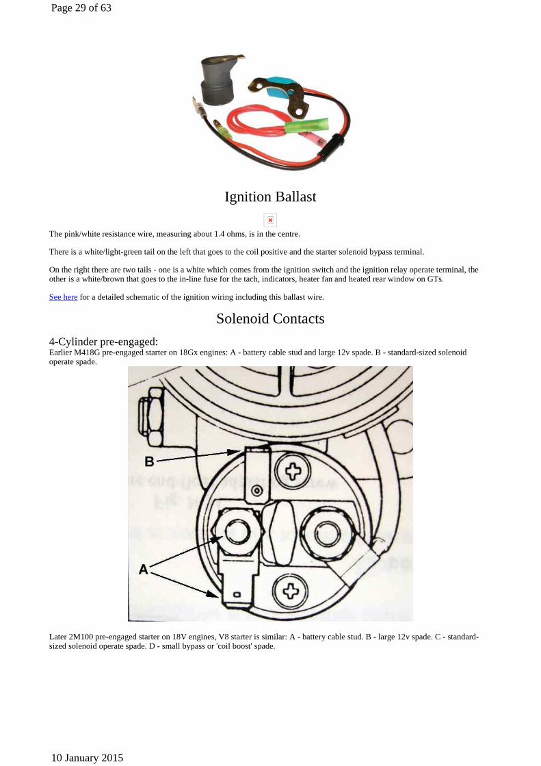
4-Cylinder pre-engaged: Earlier M418G pre-engaged starter on 18Gx engines: A - battery cable stud and large 12v spade. B - standard-sized solenoid operate spade.
Later 2M100 pre-engaged starter on 18V engines, V8 starter is similar: A - battery cable stud. B - large 12v spade. C - standard-sized solenoid operate spade. D - small bypass or 'coil boost' spade.
Page 29 of 63
10 January 2015
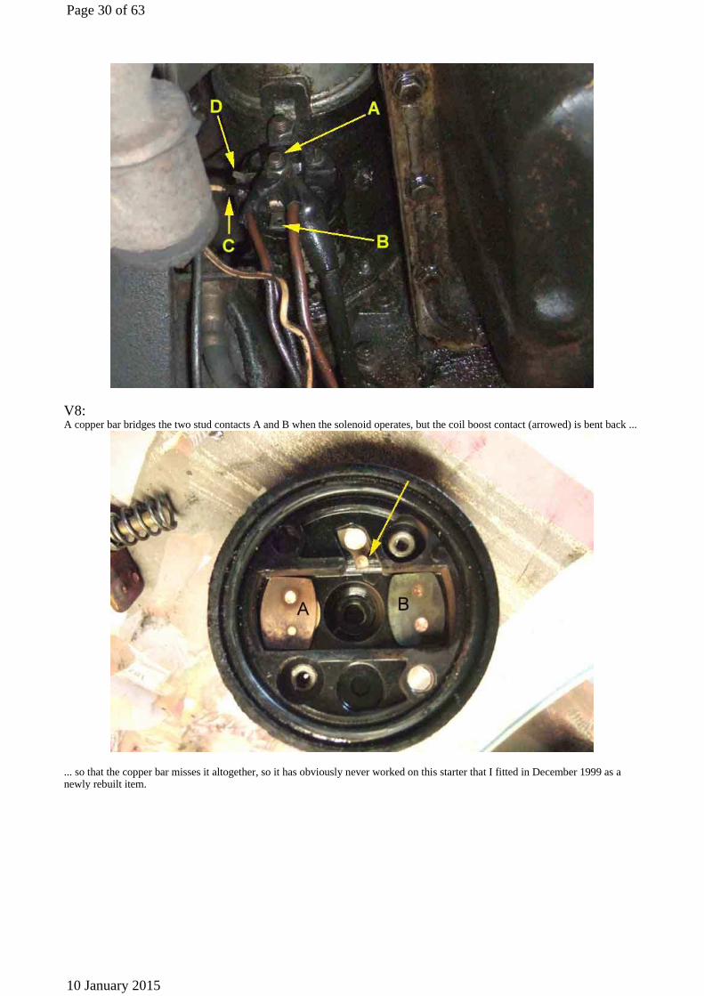
V8: A copper bar bridges the two stud contacts A and B when the solenoid operates, but the coil boost contact (arrowed) is bent back ...
... so that the copper bar misses it altogether, so it has obviously never worked on this starter that I fitted in December 1999 as a newly rebuilt item.
Page 30 of 63
10 January 2015

The coil boost contact is straightened and positioned so that the copper bar touches it and pushes it down just before it reaches the two studs.
Coil Boost Circuit with Geared/Hi-torque Starters
November 2011: In recent weeks Blake Thornton and Michael Field have contacted me about coil-boost starting systems - Blake with a problem with the factory starter relay on a Jaguar, and Michael with an after-market geared starter that doesn't have the coil boost contact that his V8 should have, and for various reasons was causing starting problems. Many of these after-market starters don't have the coil-boost contact on the solenoid as fitted originally to rubber-bumper cars and all V8s (the one I had for a while didn't). Whilst starting should be OK under most normal conditions, under marginal conditions it can make the difference between starting and not starting, and it's possible to reprovide the coil boost in a number of ways.
One way is to provide an additional auxiliary starter relay which operates in tandem with the original relay and connects 12v to the coil +ve (white/light-green on 4-cylinder cars, white/light-blue on V8), and a readily available accessories relay from all the usual suspects will do this as shown here:
Page 31 of 63
10 January 2015
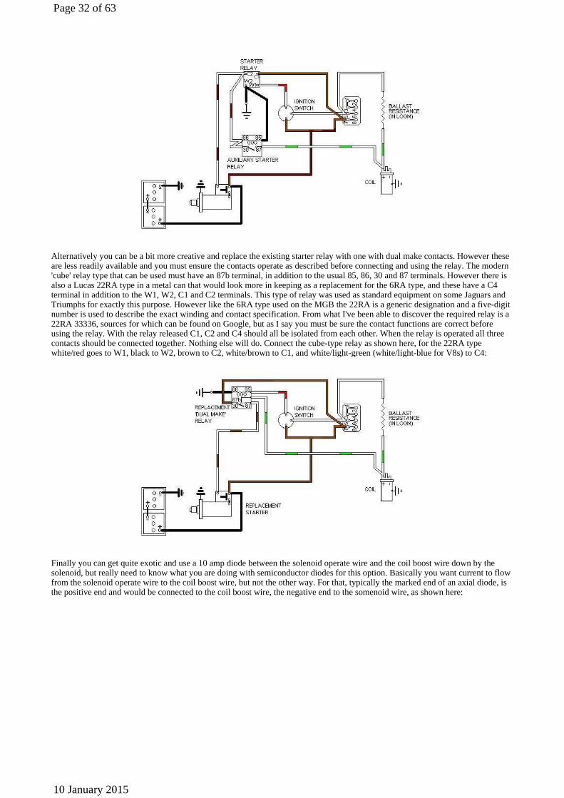
Alternatively you can be a bit more creative and replace the existing starter relay with one with dual make contacts. However these are less readily available and you must ensure the contacts operate as described before connecting and using the relay. The modern 'cube' relay type that can be used must have an 87b terminal, in addition to the usual 85, 86, 30 and 87 terminals. However there is also a Lucas 22RA type in a metal can that would look more in keeping as a replacement for the 6RA type, and these have a C4 terminal in addition to the W1, W2, C1 and C2 terminals. This type of relay was used as standard equipment on some Jaguars and Triumphs for exactly this purpose. However like the 6RA type used on the MGB the 22RA is a generic designation and a five-digit number is used to describe the exact winding and contact specification. From what I've been able to discover the required relay is a 22RA 33336, sources for which can be found on Google, but as I say you must be sure the contact functions are correct before using the relay. With the relay released C1, C2 and C4 should all be isolated from each other. When the relay is operated all three contacts should be connected together. Nothing else will do. Connect the cube-type relay as shown here, for the 22RA type white/red goes to W1, black to W2, brown to C2, white/brown to C1, and white/light-green (white/light-blue for V8s) to C4:
Finally you can get quite exotic and use a 10 amp diode between the solenoid operate wire and the coil boost wire down by the solenoid, but really need to know what you are doing with semiconductor diodes for this option. Basically you want current to flow from the solenoid operate wire to the coil boost wire, but not the other way. For that, typically the marked end of an axial diode, is the positive end and would be connected to the coil boost wire, the negative end to the somenoid wire, as shown here:
Page 32 of 63
10 January 2015

Ignition Coil Polarity This statement (highlighted below) is incorrect. On negative earth cars the distributor (i.e. the earth supply to the coil) should be connected to the - terminal, and the 12v ignition feed (the positive supply to the coil) to the + terminal.
Ignition Voltage Waveforms
Page 33 of 63
10 January 2015

Distributor O-rings Middle-era 25D4 distributor with no groove for an O-ring, note that early and late 25D4s probably had one. Note that the groove in the drive dog, or between it and the distributor body, is definitely NOT for an O-ring as some have claimed. The drive dog rotates when the engine is running of course, and if the housing extends down that far the O-ring would be ripped to pieces - or do absolutely nothing if it didn't.
Page 34 of 63
10 January 2015
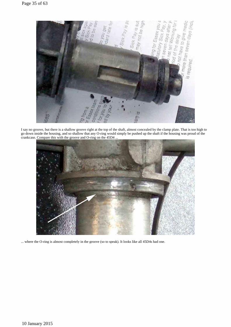
I say no groove, but there is a shallow groove right at the top of the shaft, almost concealed by the clamp plate. That is too high to go down inside the housing, and so shallow that any O-ring would simply be pushed up the shaft if the housing was proud of the crankcase. Compare this with the groove and O-ring on the 45D4 ...
... where the O-ring is almost completely in the groove (so to speak). It looks like all 45D4s had one.
Page 35 of 63
10 January 2015
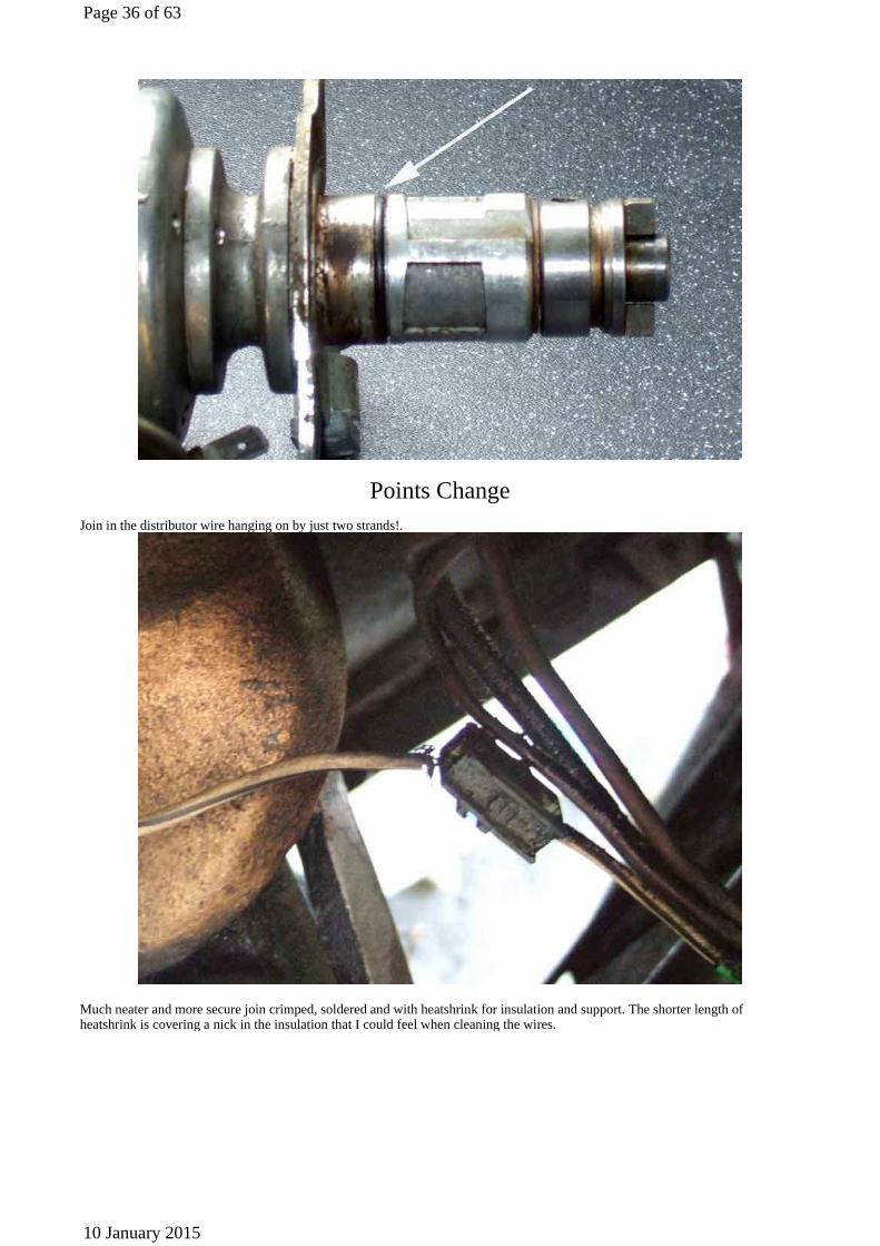
Points Change
Join in the distributor wire hanging on by just two strands!.
Much neater and more secure join crimped, soldered and with heatshrink for insulation and support. The shorter length of heatshrink is covering a nick in the insulation that I could feel when cleaning the wires.
Page 36 of 63
10 January 2015
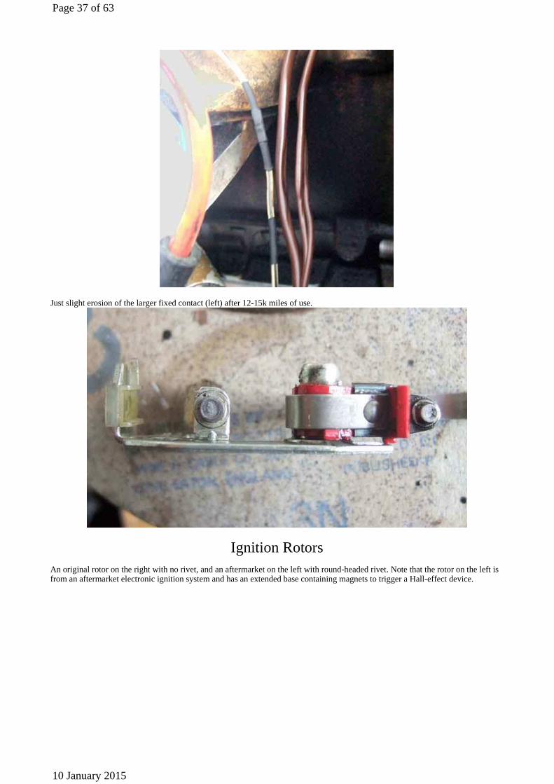
Just slight erosion of the larger fixed contact (left) after 12-15k miles of use.
Ignition Rotors An original rotor on the right with no rivet, and an aftermarket on the left with round-headed rivet. Note that the rotor on the left is from an aftermarket electronic ignition system and has an extended base containing magnets to trigger a Hall-effect device.
Page 37 of 63
10 January 2015
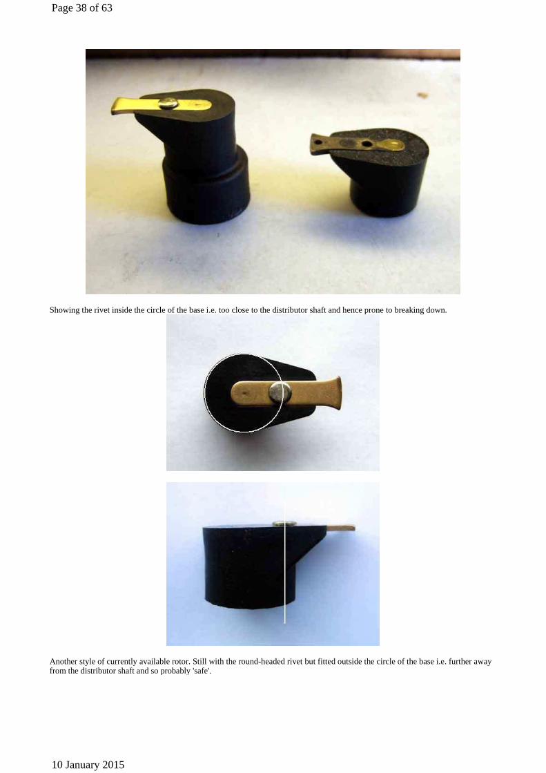
Showing the rivet inside the circle of the base i.e. too close to the distributor shaft and hence prone to breaking down.
Another style of currently available rotor. Still with the round-headed rivet but fitted outside the circle of the base i.e. further away from the distributor shaft and so probably 'safe'.
Page 38 of 63
10 January 2015
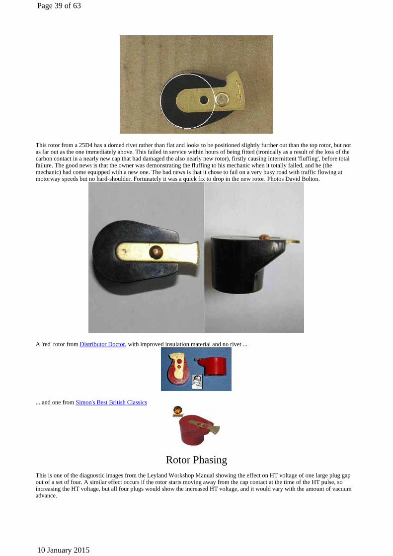
This rotor from a 25D4 has a domed rivet rather than flat and looks to be positioned slightly further out than the top rotor, but not as far out as the one immediately above. This failed in service within hours of being fitted (ironically as a result of the loss of the carbon contact in a nearly new cap that had damaged the also nearly new rotor), firstly causing intermittent 'fluffing', before total failure. The good news is that the owner was demonstrating the fluffing to his mechanic when it totally failed, and he (the mechanic) had come equipped with a new one. The bad news is that it chose to fail on a very busy road with traffic flowing at motorway speeds but no hard-shoulder. Fortunately it was a quick fix to drop in the new rotor. Photos David Bolton.
A 'red' rotor from Distributor Doctor, with improved insulation material and no rivet ...
... and one from Simon's Best British Classics
Rotor Phasing
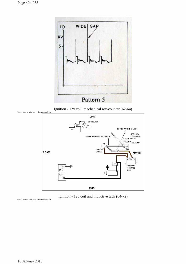
This is one of the diagnostic images from the Leyland Workshop Manual showing the effect on HT voltage of one large plug gap out of a set of four. A similar effect occurs if the rotor starts moving away from the cap contact at the time of the HT pulse, so increasing the HT voltage, but all four plugs would show the increased HT voltage, and it would vary with the amount of vacuum advance.
Page 39 of 63
10 January 2015
Ignition - 12v coil, mechanical rev-counter (62-64) Hover over a wire to confirm the colour
Ignition - 12v coil and inductive tach (64-72) Hover over a wire to confirm the colour
Page 40 of 63
10 January 2015

Note 1: Dynamo up to 1967, alternator after that. Note 2: Tach powered from white up to 1967, from green after that. Note 3: Two-fuse block up to 1969, four-fuse after that.
Ignition - 12v coil, voltage tach (73-74 1/2) Hover over a wire to confirm the colour
Ignition - 6v coil (UK 1974 1/2-1976 and all V8) Hover over a wire to confirm the colour
Page 41 of 63
10 January 2015
Note: On the factory V8 the wire from the coil to the starter solenoid is white with a blue tracer, but the wire from the harness ballast to the coil is white/light-green as shown.
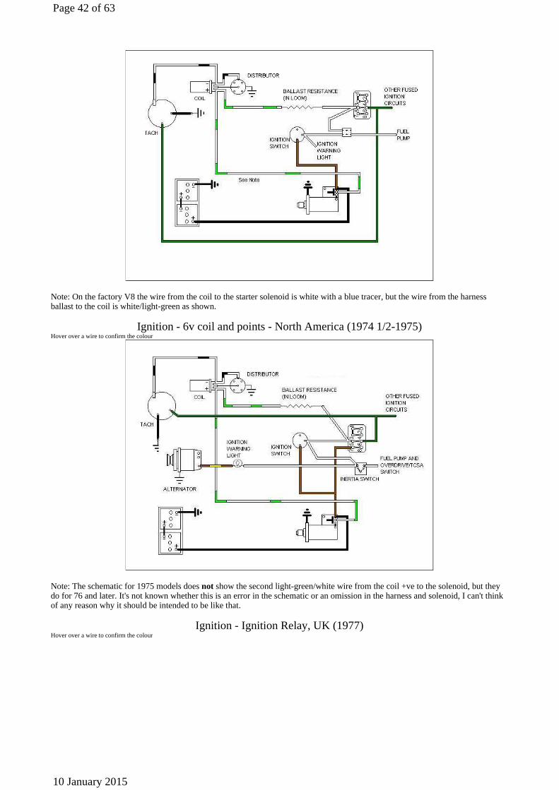
Ignition - 6v coil and points - North America (1974 1/2-1975) Hover over a wire to confirm the colour
Note: The schematic for 1975 models does not show the second light-green/white wire from the coil +ve to the solenoid, but they do for 76 and later. It's not known whether this is an error in the schematic or an omission in the harness and solenoid, I can't think of any reason why it should be intended to be like that.
Ignition - Ignition Relay, UK (1977) Hover over a wire to confirm the colour
Page 42 of 63
10 January 2015

Added January 2010: I've just noticed the Leyland Workshop Manual ('chassis number 410002 on, 1977') and Haynes ('later UK models') have slightly different schematics for late-model cars. This is the Leyland version, possibly up to 1978.
Note 1: There are two separate green circuits - the original circuit fed from the 2nd fuse up in the 4-way block for all the original green circuits, and another fed by an in-line fuse from the white/brown circuit on the relay contact for the cooling fan.
Note 2: There are two separate white circuits - one from the ignition switch feeding the ignition relay, the other feeding the fuel pump and ignition warning light taken off the white/brown circuit from the relay contact.
Note 3: I've seen round black relays on a 1980 UK model with ISO terminal numbering as follows:
Ignition - Ignition Relay, UK (78-on) Hover over a wire to confirm the colour
Updated January 2010: I've just noticed the Leyland Workshop Manual ('chassis number 410002 on, 1977') and Haynes ('later UK
Wire colour Original numberingISO numbering
White from ignition switch W1 85
Black ground W2 86
Brown 12v supply C2 30
White/brown to ignition powered circuitsC1 87
Page 43 of 63
10 January 2015

models') have slightly different schematics for late-model cars. This is the Haynes version, possibly from 1978, definitely for 1980 models.
Note 1: There are three separate green circuits - the original circuit fed from the 2nd fuse up in the 4-way block and two others each fed by their own in-line fuse - one from the white/brown circuit off the relay contact feeding the coolin fan switch, and one from the white from the ignition switch feeding indicators, heater switch, tach, and heated rear window switch.
Note 2: There are two separate white circuits - one from the ignition switch feeding the ignition relay, coil and the in-line fuse for one sub-set of the green circuits, the other feeding the fuel pump and ignition warning light off the white/brown circuit from the relay contact.
Note 3: There seem to be two separate white/brown circuits - one from the relay contact to the fusebox etc, the other from the coil white feeding the in-line for the heated rear window etc.
Note 4: I've seen round black relays on a 1980 UK model with ISO terminal numbering as follows:
Stripped Spark Plug Hole in the V8
The twenty-five thousand mile plug, in apparently good condition
The dreaded coil of alloy that came out with the new plug
Wire colour Original numberingISO numbering
White from ignition switch W1 85
Black ground W2 86
Brown 12v supply C2 30
White/brown to ignition powered circuitsC1 87
Page 44 of 63
10 January 2015
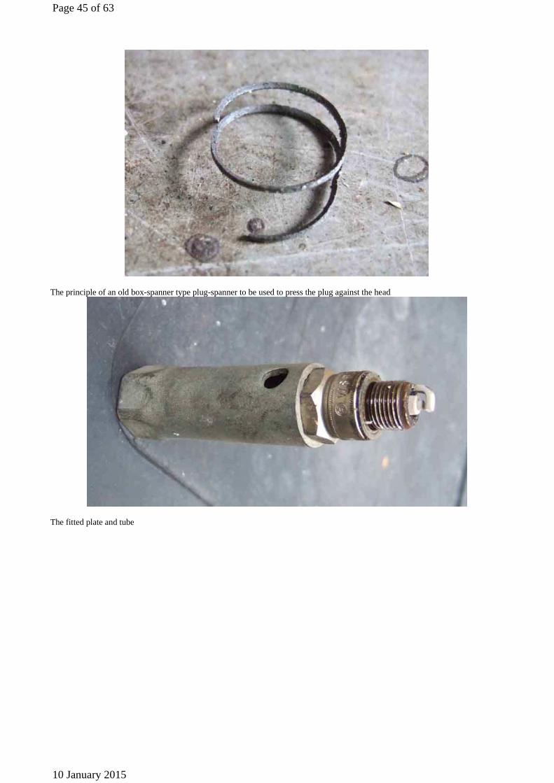
The principle of an old box-spanner type plug-spanner to be used to press the plug against the head
The fitted plate and tube
Page 45 of 63
10 January 2015
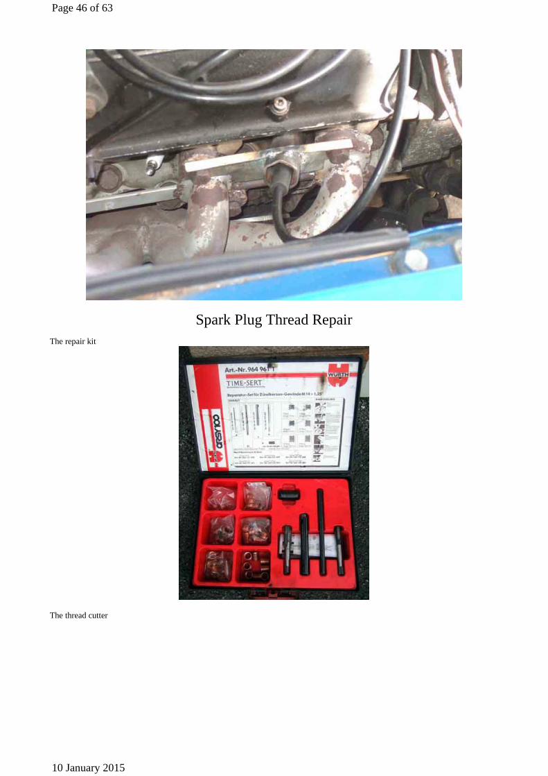
Spark Plug Thread Repair
The repair kit
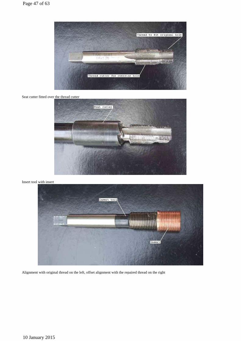
The thread cutter
Page 46 of 63
10 January 2015
Seat cutter fitted over the thread cutter
Insert tool with insert
Alignment with original thread on the left, offset alignment with the repaired thread on the right
Page 47 of 63
10 January 2015

Plug spanner having been a snug fit for many years, wearing off the chrome plating
Box-spanner plug spanner with two of the edges between the hex flats ground down as much as possible ...
... but still needed the other edges ground down a little before it would fit in the hole round the plug
Page 48 of 63
10 January 2015
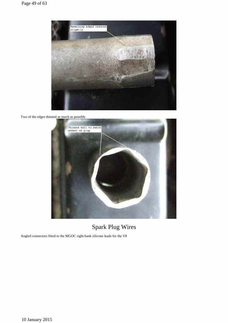
Two of the edges thinned as much as possible
Spark Plug Wires
Angled connectors fitted to the MGOC right-bank silicone leads for the V8
Page 49 of 63
10 January 2015

Separate leads 5 and 7 in the combs with lead 3 to prevent possibly parasitic ignition in cylinder 7 when 5 fires (image from Leyland MGB GT V8 Workshop Manual Supplement)
Timing Lights Basic light using an orange neon discharge tube connected in series with the HT lead. It works, but needs to be used in low ambient light conditions with the timing marks clearly marked with white paint.
Page 50 of 63
10 January 2015
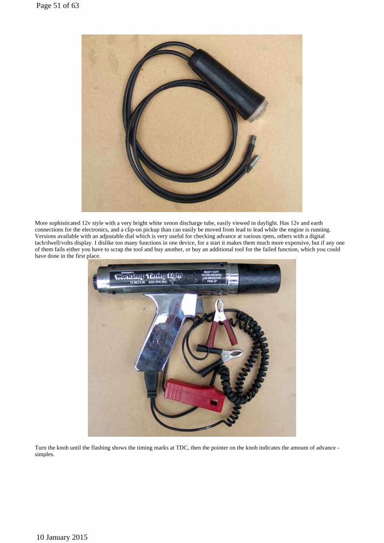
More sophisticated 12v style with a very bright white xenon discharge tube, easily viewed in daylight. Has 12v and earth connections for the electronics, and a clip-on pickup than can easily be moved from lead to lead while the engine is running. Versions available with an adjustable dial which is very useful for checking advance at various rpms, others with a digital tach/dwell/volts display. I dislike too many functions in one device, for a start it makes them much more expensive, but if any one of them fails either you have to scrap the tool and buy another, or buy an additional tool for the failed function, which you could have done in the first place.
Turn the knob until the flashing shows the timing marks at TDC, then the pointer on the knob indicates the amount of advance - simples.
Page 51 of 63
10 January 2015
Vacuum Advance
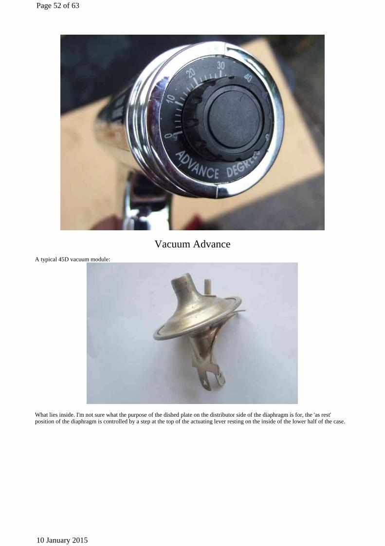
A typical 45D vacuum module:
What lies inside. I'm not sure what the purpose of the dished plate on the distributor side of the diaphragm is for, the 'as rest' position of the diaphragm is controlled by a step at the top of the actuating lever resting on the inside of the lower half of the case.
Page 52 of 63
10 January 2015

The 25D vacuum module. The a ridge on the spring-clip engages with the notches in the knurled wheel to give 'click-stops' for each fraction of a degree of adjustment. The coil spring steadies the vacuum module in the distributor body and prevents vibrations from causing small variations in timing. This is a later 25D with push-on port for rubber and plastic pipe, earlier versions had a threaded boss for a copper pipe with a separation chamber at the carb end. There should also be a small circlip to fit on the end of the threaded rod to stop the knurled wheel turning beyond the fully advanced position. It depends on how many serrations you have around the edge of your knurled wheel, and hence how many clicks for a full turn, but typically about 10 clicks equals one degree of timing adjustment. Mine has 35 serrations, and can go through 7 full turns, which gives plus or minus 12 degrees of timing adjustment from a central position.
The 25D module adjusted to the fully retarded position ...
Page 53 of 63
10 January 2015
... and the fully advanced position:
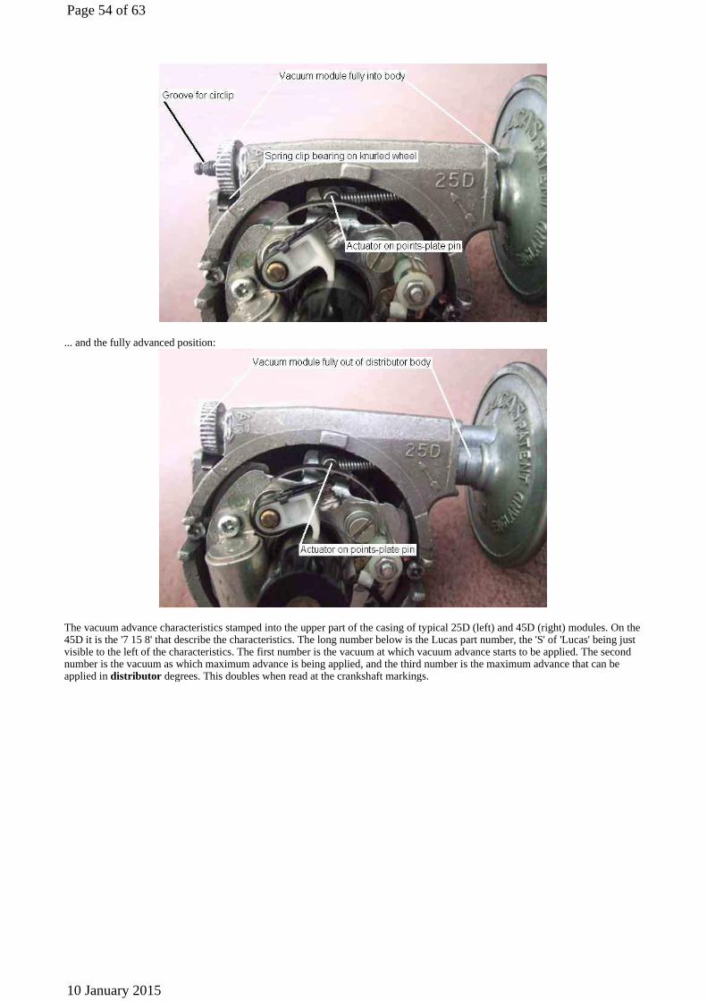
The vacuum advance characteristics stamped into the upper part of the casing of typical 25D (left) and 45D (right) modules. On the 45D it is the '7 15 8' that describe the characteristics. The long number below is the Lucas part number, the 'S' of 'Lucas' being just visible to the left of the characteristics. The first number is the vacuum at which vacuum advance starts to be applied. The second number is the vacuum as which maximum advance is being applied, and the third number is the maximum advance that can be applied in distributor degrees. This doubles when read at the crankshaft markings.
Page 54 of 63
10 January 2015
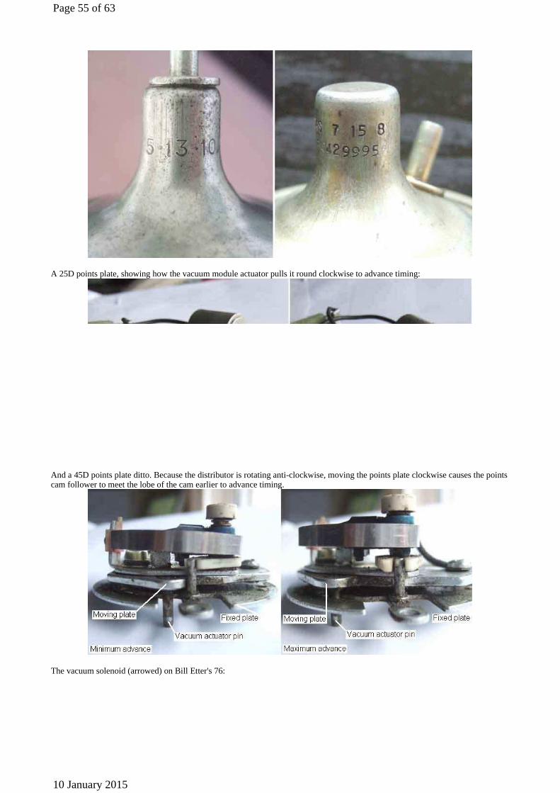
A 25D points plate, showing how the vacuum module actuator pulls it round clockwise to advance timing:
And a 45D points plate ditto. Because the distributor is rotating anti-clockwise, moving the points plate clockwise causes the points cam follower to meet the lobe of the cam earlier to advance timing.
The vacuum solenoid (arrowed) on Bill Etter's 76:
Page 55 of 63
10 January 2015
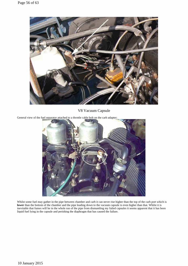
V8 Vacuum Capsule General view of the fuel separator attached to a throttle cable bolt on the carb adapter:
Whilst some fuel may gather in the pipe between chamber and carb it can never rise higher than the top of the carb port which is lower than the bottom of the chamber and the pipe leading down to the vacuum capsule is even higher than that. Whilst it is inevitable that fumes will be in the whole run of the pipe from dismantling my failed capsules it seems apparent that it has been liquid fuel lying in the capsule and perishing the diaphragm that has caused the failure.
Page 56 of 63
10 January 2015

The copper vacuum pipe and separation chamber on early 4-cylinder cars (Image from Clausager's 'Original MGB'):
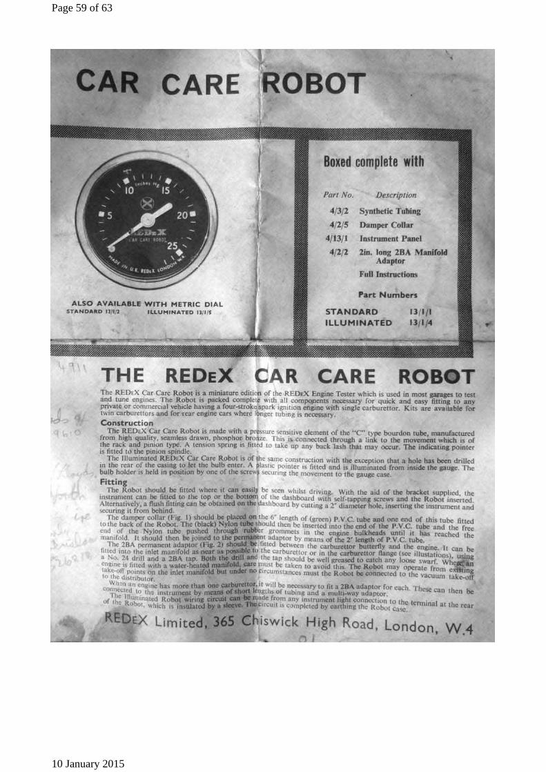
Vacuum Gauge My REDeX gauge, bought in the late 60s
Page 57 of 63
10 January 2015

The component parts
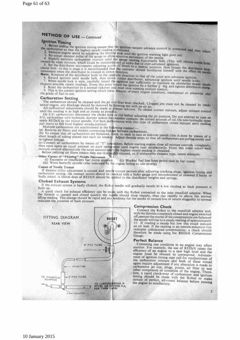
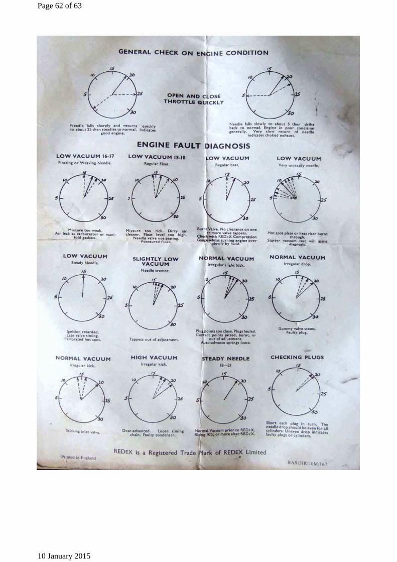
Instructions for installation and use
Page 58 of 63
10 January 2015
Page 59 of 63
10 January 2015

Page 60 of 63
10 January 2015
Page 61 of 63
10 January 2015
Page 62 of 63
10 January 2015

© Copyright 1999 to 2015 I.T. Answers. http://www.mgb-stuff.org.uk/
Page 63 of 63
10 January 2015