centrifugal liquid chillers - surplus group · the york optiview control center, furnished as...
TRANSCRIPT
Centrifugal Liquid ChillersMODEL YT Design Level J
150 THROUGH 850 TONS(527 through 2989 kW)
Utilizing HCFC-123
FORM 160.55-EG1 (901)
��������������
00613VIP
Rated in Accordance with the latest edition ofARI STANDARD 550/590

YORK INTERNATIONAL2
TABLE OF CONTENTS
NOMENCLATURE
YT K3 C4 E2 – CR J S
Special FeaturesModel
Design LevelEvaporator Code
Motor CodeCondenser Code
Power SupplyCompressor Code – for 60 Hz
5 for 50 Hz
The model number denotes the following characteristics of the unit.
Introduction ............................................................................................................. 3
Ratings ................................................................................................................... 4
OptiView Control Center .........................................................................................5
Mechanical Specifications ..................................................................................... 13
Accessories and Modifications .............................................................................. 18
Application Data .................................................................................................... 20
Dimensions (Ft. - In.) ............................................................................................ 30
Dimensions (mm) ................................................................................................. 32
Dimensions (Ft. - In.) – Nozzle Arrangements ...................................................... 34
Evaporators – Compact Water Boxes ............................................................. 34
Condensers – Compact Water Boxes ............................................................. 35
Evaporators – Marine Water Boxes ................................................................ 36
Condensers – Marine Water Boxes ................................................................ 37
Dimensions (mm) – Nozzle Arrangements ........................................................... 38
Evaporators – Compact Water Boxes ............................................................. 38
Condensers – Compact Water Boxes ............................................................. 39
Evaporators – Marine Water Boxes ................................................................ 40
Condensers – Marine Water Boxes ................................................................ 41
Weights – Lbs. ...................................................................................................... 42
Weights – Kg ........................................................................................................ 44
Guide Specifications ............................................................................................. 46
SI Metric Coversion .............................................................................................. 52
FORM 160.55-EG1
3YORK INTERNATIONAL
Introduction
The YORK MAXE™ YT Chillers offer a complete combi-nation of features for total owner satisfaction.
MATCHED COMPONENTS MAXIMIZE EFFICIENCY
Actual chiller efficiency cannot be determined by ana-lyzing the theoretical efficiency of any one chiller com-ponent. It requires a specific combination of heat ex-changer, compressor, and motor performance toachieve the lowest system kW/Ton. YORK MAXE chillertechnology matches chiller system components to pro-vide maximum chiller efficiency under actual – not justtheoretical – operating conditions.
REAL-WORLD ENERGY PERFORMANCE
YORK pioneered the term “Real-World Energy” to illus-trate the energy-saving potential of focusing on chillerperformance during off-design conditions. Off-design isnot only part load, but full load operation as well, withreduced entering condenser water temperatures(ECWTs). This is where chillers operate 99% of the time,and where operating costs add up.
The YK MAXE chillers are the only chillers designed tooperate on a continuous basis with cold ECWT and fullcondenser flow at all load points, taking full advantageof Real-World conditions. This type of operation ben-efits the cooling tower as well; reducing cycling of thefan motor and ensuring good coverage of the coolingfill.
YORK MAXE chillers offer the most efficient Real-Worldoperation of any chiller, meaning lower operating costsand an excellent return on your chiller investment.
OPEN DRIVE DESIGN
Hermetic-motor burnout can cause catastrophic dam-age to a chiller. The entire chiller must be cleaned, andthe refrigerant replaced. YORK MAXE centrifugal chill-ers eliminate this risk by utilizing air-cooled motors. Re-frigerant never comes in contact with the motor, pre-venting contamination of the rest of the chiller.
Insurance companies that offer policies on large air con-ditioning equipment often consider air-cooled motors asignificant advantage over hermetic refrigerant-cooledunits.
HIGH-EFFICIENCY HEAT EXCHANGERS
MAXE chiller heat exchangers offer the latest technologyin heat transfer surface design to give you maximumefficiency and compact design. Water-side andrefrigerant-side design enhancements minimize bothenergy consumption and tube fouling.
SINGLE-STAGE COMPRESSOR DESIGNAND EFFICIENCY PROVEN IN THEMOST DEMANDING APPLICATIONS
Designed to be the most reliable chillers we’ve evermade, YORK MAXE chillers incorporate single-stagecompressor design. With fewer moving parts andstraight-forward, efficient engineering, YORK single-stage compressors have proven durability records inhospitals, chemical plants, gas processing plants, theU.S. Navy, and in other applications where minimaldowntime is a crucial concern.
In thousands of installations worldwide, YORK single-stage compressors are working to reduce energy costs.Lightweight, high strength aluminum compressor impel-lers feature backward-curved vanes for high efficiency.Airfoil shaped pre-rotation vanes minimize flow disrup-tion for the most efficient part-load performance. Pre-cisely positioned and tightly fitted they allow the com-pressor to unload smoothly from 100% to minimum loadfor minimum air conditioning applications.
FACTORY PACKAGINGREDUCES FIELD LABOR COSTS
YORK MAXE centrifugal chillers are designed to keepinstallation costs low. Where installation access is nota problem, the unit can be shipped completely pack-aged, requiring minimal piping and wiring to completethe installation.
For those units utilizing Variable Speed Drive or a fac-tory installed Solid-State Starter, the three power leadsprovide all power to the chiller and its auxiliaries.
TAKE ADVANTAGE OF COLDER COOLING TOWERWATER TEMPERATURES
YORK MAXE centrifugal chillers have been designed totake full advantage of colder cooling tower water tem-peratures, which are naturally available during most op-erating hours. Considerable energy savings are avail-able by letting tower water temperature drop, rather thanartificially holding it above 75°F (23.9°C), especially atlow load, as some chillers require.
U.L. ACCEPTANCE – YOUR ASSURANCE OFRELIABILITY
YORK MAXE centrifugal chillers are approved for listingby Underwriter’s Laboratories for the United States andCanada. Recognition of safety and reliability is your as-surance of trouble-free performance in day-today build-ing operation.

YORK INTERNATIONAL4
Ratings
ARI CERTIFICATION PROGRAM
The performance of YORK MAXE chillers has been cer-tified to the Air Conditioning and Refrigeration Institute(ARI) as complying with the certification sections of thelatest issue of ARI Standard 550/590. Under this Certifi-cation Program, chillers are regularly tested in strictcompliance with this Standard. This provides an inde-pendent, third-party verification of chiller performance.
COMPUTERIZED PERFORMANCE RATINGS
Each chiller is custom-matched to meet the individualbuilding load and energy requirements. A large numberof standard heat exchangers and pass arrangementsare available to provide the best possible match.
It is not practical to provide tabulated performance foreach combination, as the energy requirements at bothfull and part-load vary significantly with each heat ex-changer and pass arrangement. Computerized ratingsare available through each YORK sales office. These
ratings can be tailored to specific job requirements, andare part of the ARI Certification Program.
OFF-DESIGN PERFORMANCE
Since the vast majority of its operating hours are spentat off-design conditions, a chiller should be chosen notonly to meet the full-load design, but also for its abilityto perform efficiently at lower loads and lower towerwater temperatures. It is not uncommon for chillers withthe same full-load kW/TON to have an operating costdifference of over 10% due to part-load operation.
Part-load information can be easily and accurately gen-erated by use of the computer. And because it is soimportant to an owner’s operating budget, this informa-tion has now been standardized within the ARI Certifi-cation Program in the form of an Integrated Part-LoadValue (IPLV), and Non-Standard Part-Load Value(NPLV)
The IPLV / NPLV formulas from ARI Standard 550/590much more closely track actual chiller operations, andprovide a more accurate indication of chiller perfor-mance than the previous IPLV / APLV formula. A moredetailed analysis must take into account actual buildingload profiles, and local weather data. Part-load perfor-mance data should be obtained for each job using itsown design criteria.
Rated in accordance with the lat-est issue of ARI Standard 550/590.

FORM 160.55-EG1
5YORK INTERNATIONAL
OptiView Control Center
The YORK OptiView Control Center, furnished as stan-dard on each chiller, provides the ultimate in efficiency,monitoring, data recording, chiller protection and oper-ating ease. The control center is a factory mounted,wired and tested state-of-the-art microprocessor basedcontrol system for HCFC-123 centrifugal chillers. Thepanel is configured with a 10.4-in. diagonal color LiquidCrystal Display (LCD) surrounded by “soft” keys, whichare redefined with one keystroke based on the screendisplayed at that time. This revolutionary developmentmakes chiller operation quicker and easier than everbefore. Instead of requiring keystroke after keystroketo hunt for information on a small mono-chrome LCDscreen, a single button reveals a wide array of informa-tion on a large, full-color illustration of the appropriatecomponent, which makes information easier to inter-pret. This is all mounted in the middle of a keypad inter-face and installed in a locked enclosure.
LCD display allows graphic animated display of thechiller, chiller sub-systems and system parameters; thisallows the presentation of several operating parametersat once. In addition, the operator may view a graphicalrepresentation of the historical operation of the chilleras well as the present operation. A Status Bar is dis-played at all times on all screens, it contains the Sys-tem – Status Line and Details Line, the Control Source,Access Level, Time and Date. All date representationsand calculations use four digits for the year to provideYear 2000 compliance.
During prelube and coastdown, the system status willinclude a countdown timer indicating the time remain-ing. The control panel is compatible with the YORK SolidState Starter (optional); YORK Variable Speed Drive(VSD) (Optional), Electro-Mechanical (E-M) starter orany customer supplied E-M starter that complies withthe YORK R-1051 standard. The locations of various
chiller parameters are clearly marked and instructionsfor specific operations are provided on many of thescreens. The panel verbiage is available in other lan-guages as an option with English always available. Datacan be displayed in either English or Metric units pluskeypad entry of setpoints to 0. 1 increments.
Security access is provided to prevent unauthorizedchanges of setpoints. This is accomplished with threedifferent levels of access and passwords for each level.There are certain screens, displayed values, program-mable setpoints and manual controls not shown thatare for servicing the chiller. They are only displayed whenlogged in at service access level. Included in this is theAdvanced Diagnostics and troubleshooting informationfor the chiller and the panel.
The control center is supplied through a 1-1/2 KVA trans-former in the compressor motor starter to provide indi-vidual over-current protected power for all controls.Numbered terminal strips for wiring such as RemoteStart/Stop, Flow Switches, Chilled Water Pump andLocal or Remote Cycling devices are provided. ThePanel also provides field interlocks that indicate thechiller status. These contacts include a Remote ModeReady-To-Start, a Cycling Shutdown, a Safety Shutdownand a chiller Run contact. Pressure transducers sensesystem pressures and thermistors sense system tem-peratures. The output of each transducer is a DC volt-age that is analogous to the pressure input. The outputof each thermistor is a DC voltage that is analogous tothe temperature it is sensing.
Setpoints can be changed from a remote location via 0-10VDC, 4-20mA, contact closures or through serial com-munications. The adjustable remote reset range [up to20°F (11.1°C)] provides flexible, efficient use of remotesignal depending on reset needs. Serial data interface
00614VIP

YORK INTERNATIONAL6
OptiView Control Center (continued)
to the YORK ISN Building Automation System (BAS) isthrough the optional General Protocol Interface Card(GPIC), which can be mounted inside the control center.
This printed circuit board requests the required data fromthe Micro Board and makes it available for the YORKISN network. This optional board is available through theYORK BAS group. The operating program is stored innon-volatile memory (EPROM) to eliminate chiller fail-ure due to AC power failure/battery discharge. Pro-grammed setpoints are retained in lithium battery-backedRTC memory for 11 years minimum.
Smart Freeze Point Protection will run the chiller at 36°F(2.22°C) leaving chilled water temperature, and not havenuisance trips on Low Water Temperature. The sophis-ticated program and sensor will monitor the chiller wa-ter temperature to prevent freeze up. Every program-mable point has a pop-up screen with the allowableranges, so that the chiller can not be programmed tooperate outside of its design limits.
When the power is applied to the chiller the HOMEscreen is displayed. This screen displays a visual rep-resentation of the chiller and a collection of data detail-ing important operations and parameters. When thechiller is running, the flow of chilled liquid is animatedby the alternating shades of color moving in and out ofthe pipe nozzles. The primary values that need to bemonitored and controlled are shown on this screen. Theyare as follows:
Display Only
• Chilled Liquid Temperature – Leaving
• Chilled Liquid Temperature – Return
• Condenser Liquid Temperature – Return
• Condenser Liquid Temperature – Leaving
• Motor Run (LED)
• % Full Load Amps
• Operating Hours
• Input Power (kW) (VSD Only)
With the “soft” keys the operator is only one touch awayfrom the 8 main screens that allow access to the ma-jor information and components of the chiller. The 8screens are the SYSTEM, EVAPORATOR, CON-DENSER, COMPRESSOR, OIL SUMP, MOTOR,SETPOINTS and the HISTORY. Also on the Homescreen is the ability to Log IN, Log Out and Print. LogIn and Log Out is the means by which different secu-rity levels are accessed.
The SYSTEM screen gives a general overview of com-mon chiller parameters for both shells. This is an endview of the chiller with a 3-D cutaway of both the shells.From this screen you can view the following:
Display Only
• Discharge Temperature
• Chilled Liquid Temperature – Leaving
• Chilled Liquid Temperature – Return
• Chilled Liquid Temperature – Setpoint
• Evaporator Pressure
• Evaporator Saturation Temperature
• Condenser Liquid Temperature - Leaving
• Condenser Liquid Temperature - Return
• Condenser Pressure
• Condenser Saturation Temperature
• Oil Sump Temperature
• Oil Pressure
• % Full Load Amps
• Current Limit
The EVAPORATOR screen displays a cutaway viewof the chiller evaporator. All setpoints relating to theevaporator side of the chiller are maintained on thisscreen. Animation of the evaporation process indicateswhether the chiller is presently in RUN condition (bub-bling) and liquid flow in the pipes is indicated by alter-nating shades of color moving in and out of the pipes.Adjustable limits on the low water temperaturesetpoints allows the chiller to cycle on and off forgreater efficiency and less cycling. The chiller cyclesoff when the leaving chilled water temperature is be-low setpoint and adjustable from 1°F (.55°C) below toa minimum of 36°F (2.2°C). Restart is adjustable fromsetpoint up to a maximum of 80°F (44.4°C). The Panelwill check for flow to avoid freeze up of the tubes. Ifflow is interrupted, shutdown will occur after a mini-mum of two seconds. From this screen you can per-form the following:
Display Only
• Chilled Liquid Flow Switch (Open/Closed)
• Chilled Liquid Pump (Run/Stop)
• Evaporator Pressure
• Evaporator Saturation Temperature
• Return Chilled Liquid Temperature
• Leaving Chilled Liquid Temperature
• Evaporator Refrigerant Temperature

FORM 160.55-EG1
7YORK INTERNATIONAL
• Small Temperature Difference
• Leaving Chilled Liquid Temperature Setpoints –Setpoint
• Leaving Chilled Liquid Temperature Setpoints –Shutdown
• Leaving Chilled Liquid Temperature Setpoints –Restart
Programmable
• Local Leaving Chilled Liquid Temperature – Range
• Local Leaving Chilled Liquid Temperature – Setpoint
• Leaving Chilled Liquid Temperature Cycling Offset –Shutdown
• Leaving Chilled Liquid Temperature Cycling Offset –Restart
The CONDENSER screen displays a cutaway view ofthe chiller condenser. The liquid flow is animated to in-dicate flow through the condenser. All setpoints relat-ing to the condenser side of the chiller are maintainedon this screen. With the proper access level this screenalso serves as a gateway to controlling the RefrigerantLevel. From this screen you can view the following:
Display Only
• Leaving Condenser Liquid Temperature
• Return Condenser Liquid Temperature
• Condenser Pressure
• Condenser Saturation Temperature
• Small Temperature Difference
• Drop Leg Refrigerant Temperature
• Sub-Cooling Temperature
• High Pressure Switch (Open/Closed)
• Condenser Liquid Flow Switch
• Condenser Liquid Pump (Run/Stop)
The PURGE screen displays a cutaway view of thepurge tank, where all setpoints relating to the purgesystem are maintained on this screen. LEDs depict thestate of the Float switches, Oil Valve solenoid, Air Valvesolenoid and the Purge exhaust count is displayed. Fromthis screen you can view the following:
Display Only
• Air Valve Solenoid (LED)
• Top Float Switch (LED)
• Bottom Float Switch (LED)
• Oil Valve Solenoid (LED)
• Pressure
• Exhaust Count
• Exhaust Window
• Bypass Time Left
Programmable
• Maximum Purges/Hour
The COMPRESSOR screen displays a cutaway viewof the compressor, this reveals the impeller and showsall the conditions associated with the compressor. Whenthe compressor impeller is spinning this indicates thatthe chiller is presently in RUN condition. With the properaccess level, the pre-rotation vanes may be manuallycontrolled. This screen also serves as a gateway tosub-screens for calibrating the prerotation vanes, theproximity probe, configuring the Hot Gas By-Pass, orproviding advanced control of the compressor motorVariable Speed Drive. From this screen you can viewthe following:
Display Only
• Oil Pressure
• Oil Sump Temperature
• Discharge Temperature
• Superheat Temperature
• Vane Motor Switch (LED)
• Vent Line Solenoid (LED)
The OIL SUMP screen displays a close-up view of thechiller oil sump and provides all the necessary setpointsfor maintaining the Variable Speed Oil Pump (VSOP).This screen also allows manual control of the FrequencyCommand sent to the VSOP. From this screen you canperform the following:
Display Only
• Oil Sump Temperature
• Oil Pressure
• Oil Pump Run Output (LED)
• Manual Oil Pump Operation Time Left
Programmable
• Manual Pump
1. The MOTOR “soft” key on the Home screen whenpressed, shows a picture of either a YORKElectro-Mechanical Starter, Solid State Starter or aVariable Speed Drive Screen depending on chillerconfiguration. Programmable pulldown demand toautomatically limit motor loading for minimizing

YORK INTERNATIONAL8
building demand charges. Pulldown time period con-trol over four hours, and verification of time remain-ing in pulldown cycle from display readout. Sepa-rate digital setpoint for current limiting between 30and 100%.
The ELECTRO-MECHANICAL STARTER – (E-M)screen displays a picture of the starter and the follow-ing values. The ones below are common among all threeofferings and the values will be displayed on all types ofstarter screens. From this screen you can perform thefollowing:
Display Only
• Motor Run (LED)
• Motor Current % Full Load Amps
• Current Limit Setpoints
• Pulldown Demand Time Left
Programmable
• Local Motor Current Limit
• Pulldown Demand Limit
• Pulldown Demand Time
The SOLID STATE STARTER – (SSS) screen displaysa picture of the starter and following values that aredisplayed in addition to the common ones listed above.
Display Only
• Input Power
• kW Hours
• Starter Model Voltage – Phase A, B, C
• Current – Phase A, B, C
• Temperature – Phase A, B, C
The VARIABLE SPEED DRIVE – (VSD) screen dis-plays a picture of the VSD and the following values thatare in addition to the common ones listed above. Fromthis screen you can view the following:
Display Only
• Output Voltage
• Output Frequency
• Current – Phase A, B, C
• Input Power
• kW Hours
• Pre-Rotation Vane Position
• Harmonic Filter Data (Filter option only)
• Supply KVA
• Total Power Factor
• Voltage Total Harmonic Distortion –
L1, L2, L3
• Supply Current Total Demand Distortion –
LI, L2, L3
There are two additional screens (Sub-Screens) thathave further VSD information. From these screens youcan view the following:
1) Variable Speed Drive Details
Display Only
• Water Pump Output (LED)
• Precharge Relay Output (LED)
• Trigger SCR Output (LED)
• DC Bus Voltage
• DC Inverter Link Current
• Internal Ambient Temperature
• Converter Heatsink Temperature
• Heatsink Temperature – Phase A, B, C
• Motor HP
• 100% Full Load Amps
2) Harmonic Filter Details (Filter option only)
Display Only
• Operating Mode (Run/Stop)
• DC Bus Voltage
• Supply Contactor (LED)
• Precharge Contactor (LED)
• Phase Rotation
• Total Supply KVA
• Heatsink Temperature (Harmonic Filter)
• Voltage Peak (N-L1, N-L2, N-L3)
• RMS Voltage (L1, L2, L3)
• Voltage Total Harmonic Distortion (L1, L2, L3)
• RMS Filter Current (L1, L2, L3)
• Supply Current Total Demand Distortion
• RMS Supply Current (L1, L2, L3)
The SETPOINTS screen provides a convenient loca-tion for programming the most common setpoints in-volved in the chiller control. The Setpoints are shownon other individual screens but to cut down on need-less searching they are on this one screen. This screenalso serves as a gateway to a sub-screen for definingthe setup of general system parameters. From thisscreen you can perform the following:
OptiView Control Center (continued)
FORM 160.55-EG1
9YORK INTERNATIONAL
Display Only
• Leaving Chilled Liquid Temperature – Setpoint
• Leaving Chilled Liquid Temperature Cycling – Shut-down
• Leaving Chilled Liquid Temperature Cycling – Re-start
• Current Limit Setpoint
Programmable
• Local Leaving Chilled Liquid Temperature – Range
• Local Leaving Chilled Liquid Temperature – Setpoint
• Leaving Chilled Liquid Temperature Cycling Offset –Shutdown
• Leaving Chilled Liquid Temperature Cycling Offset –Restart
• Remote Analog Input Range
• Local Motor Current Limit
• Pulldown Demand Limit
• Pulldown Demand Time
The SETUP is the top level of the general configurationparameters. It allows programming of the time and date,along with specifications as to how the time will be dis-played. In addition, the chiller configuration as deter-mined by the micro board program jumpers and pro-gram switches is displayed. From this screen you canperform the following.
Display Only
• Chilled Liquid Pump Operation: (Displays Standardor Enhanced)
• Motor Type: (Displays Fixed Speed or VariableSpeed)
• Refrigerant Selection: (Displays R-123)
• Anti-Recycle: (Displays Disable or Enabled)
• Power Failure Restart: (Displays Manual or
Automatic)
• Liquid Type: (Water or Brine)
• Coastdown: (Displays Standard or Enhanced)
• Pre-Run: (Displays Standard or Extended)
• Power Line Frequency (VSD only): (Displays 60 Hzor 50 Hz)
Programmable
• Set Date
• Set Time
• Clock (Enabled/Disabled)
• 12/24 Hr.
The following 6 sub-screens can be accessed from thesetup screen:
The SCHEDULE screen contains more programmablevalues than a normal display screen. Each program-mable value is not linked to a specific button; insteadthe select key is used to enable the cursor arrows andcheck key to program the Start/Stop times for any dayof the week up to 6 weeks in advance. The user hasthe ability to define a standard set of Start/Stop timesthat are utilized every week or specify exceptions to cre-ate a special week.
Programmable
• Exception Start/Stop Times
• Schedule (Enable/ Disabled)
• Repeat Sunday Schedule
• Standard Week Start/Stop Times
• Reset All Exception Days
• Select
The USER screen allows definition of the language forthe chiller to display and defines the unit of measure.
Programmable
• System Language
• English / Metric Units
The COMMS screen allows definition of the necessarycommunications parameters.
Programmable
• Chiller ID
• Com 2 Baud Rate
• Com 2 Data Bit(s)
• Com 2 Parity Bit(s)
• Com 2 Stop Bit(s)
• Printer Baud Rate
• Printer Data Bit(s)
• Printer Parity Bit(s)
• Printer Stop Bit(s)
The PRINTER screen allows Definition of the neces-sary communications Parameters for the printer.
Display Only
• Time Remaining Until Next Print
YORK INTERNATIONAL10
Programmable
• Log Start Time
• Output Interval
• Automatic Printer Logging (Enabled/Disabled)
• Print Type
• ACC Auto Map Print (Enable/Disabled)
• ACC Map Report
• Print Report
• Print All Histories
The SALES ORDER screen allows definition of the or-der parameters. Note: This information is loaded at thefactory or by the installation/service technician.
Display Only
• Model Number
• Panel Serial Number
• Chiller Serial Number
• YORK Order Number
• System Information
• Condenser and Evaporator Design Load
Information
• Nameplate Information
The OPERATIONS screen allows definition of param-eters having to do with operation of the chiller. What isdefined is whether the control of the chiller will be Lo-cal, Digital Remote, Analog Remote, Modem Remoteor ISN Remote.
Programmable
• Control Source
The HISTORY screen allows the user to browse throughthe last ten faults; either safety or cycling shutdownswith the conditions while the chiller is running or stopped.The faults are color coded for ease in determining theseverity at a glance, recording the date, time and de-scription. (See Display Messages for Color Codemeanings.)
Display Only
• Last Normal Shutdown
• Last Fault While Running
• Last Ten Faults
Programmable
• Print History
• Print All Histories
By pressing the VIEW DETAILS key you will move tothe HISTORY DETAILS screen. From these screensyou are able to see an on-screen printout of all the sys-tem parameters at the time of the selected shutdown.
Display Only
• History Printout
Programmable
• Page Up
• Page Down
• Print History
Also under the History screen is the TRENDING screen,accessible by the key marked the same. On this screenup to 6 operator-selected parameters selected from alist of over 140, can be plotted in an X/Y graph format.The graph can be customized to record points onceevery second, up to once every hour. There are twotypes of charts that can be created: a single or continu-ous screen. The single screen collects data for onescreen width (450 data points across the x-axis) thenstops. The continuous screen keeps collecting the databut the oldest data drops off the graph from left to rightat the next data collection interval. For ease of identifi-cation, each plotted parameter, title and associated y-axis labeling is color coordinated.
Display Only
• This screen allows the user to view the graphicaltrending of the selected parameters and is a gate-way to the graph setup screens.
Programmable
• Start
• Stop
• y-axis
• x-axis
The TREND SETUP screen is used to configure thetrending screen. The parameters to be trended are se-lected from the Trend Common Slots Screen accessedfrom the Slot #s button or the Master Slot Numbers Listfound in the operating manual. The interval at which allthe parameters are sampled is selected under the Col-lection Interval button. The data point minimum andmaximum values may be adjusted closer within therange to increase viewing resolution.
Programmable
• Chart Type (select Continuous or One Screen)
• Collection Interval
OptiView Control Center (continued)
FORM 160.55-EG1
11YORK INTERNATIONAL
• Select
• Data Point Slot # (1-6)
• Data Point Min (1-6)
• Data Point Max (1-6)
The TREND COMMON SLOTS screen displays theMaster Slot Numbers List of the monitored parameters.
Display Only
• Slot Numbers
Programmable
• Page Up
• Page Down
DISPLAY MESSAGES
The control center continually monitors the operatingsystem displaying and recording the cause of any shut-downs (Safety, Cycling or Normal). The condition of thechiller is displayed at the System Status line that con-tains a message describing the operating state of thechiller; whether it is stopped, running, starting or shut-ting down. A System Details line displays Warning, Cy-cling, Safety, Start Inhibit and other messages that pro-vide further details of Status Bar messages. Messagesare color-coded Green – Normal Operations, Yellow –Warnings, Orange – Cycling Shutdowns, and Red –Safety Shutdowns to aid in identifying problems quickly.
Status Messages include:
• System Ready To Start
• Cycling Shutdown – Auto Restart
• Safety Shutdown – Manual Restart
• System Prelube (with countdown timers)
• System Run (with countdown timers)
• System Coastdown (with countdown timers)
• Start Inhibit
• Vanes Closing Before Shutdown
Run Messages include:
• Motor – High Current Limit
• Leaving Chilled Liquid Control
• Motor Pulldown Limit
Start Inhibit Messages include:
• Anti-Recycle XX Min/Sec
• Vane Motor Switch Open
• Motor Current >15% FLA
• LCSSS – High Temperature Phase X - Stopped
Warning Messages include:
• Real Time Clock Failure
• Condenser or Evaporator Transducer Error
• Setpoint Override
• Condenser – High Pressure Limit
• Evaporator – Low Pressure Limit
• Vanes Uncalibrated – Fixed Speed (VSD optiononly)
• Purge – High Pressure
• Purge – Float Switch Error
• Purge – Excess Purge
• Vanes Uncalibrated (Hot Gas Bypass Option Only)
• External I/O – Serial Communications
(Filter option only)
• Harmonic Filter – Operation Inhibited
• Harmonic Filter – Data Loss
• Harmonic Filter – Input Frequency Range
Routine Shutdown Messages include:
• Remote Stop
• Local Stop
• Place Compressor Switch In Run Position
Cycling Shutdown Messages include:
• Multi-unit Cycling – Contacts Open
• System Cycling – Contacts Open
• Oil – Low Temperature
• Control Panel – Power Failure
• Leaving Chilled Liquid – Low Temperature
• Leaving Chilled Liquid – Flow Switch Open
• Condenser – Flow Switch Open
• Motor Controller – Loss of Current
• Power Fault
• Control Panel – Schedule
LCSSS Only
• Initialization Failed
• Serial Communications
• Shutdown – Requesting Fault Data...
• Stop Contacts Open

YORK INTERNATIONAL12
OptiView Control Center (continued)
• Power Fault
• Low Phase X Temperature Sensor
• Run Signal
• Invalid Current Scale Selection
• Phase Locked Loop
• Low Supply Line Voltage
• High Supply Line Voltage
• Logic Board Processor
• Phase Rotation / Loss
• Logic Board Power Supply
Compressor Motor Variable Speed Drive: CyclingShutdown Messages include (VSD only):
• VSD Shutdown – Requesting Fault Data
• VSD – Stop Contacts Open
• VSD Initialization Failed
• VSD – High Phase A, B, C Instantaneous Current
• VSD – Phase A, B, C Gate Driver
• VSD – Single Phase Input Power
• VSD – High DC Bus Voltage
• VSD – Logic Board Power Supply
• VSD – Low DC Bus Voltage
• VSD – DC Bus Voltage Imbalance
• VSD – Precharge – DC Bus Voltage Imbalance
• VSD – High Internal Ambient Temperature
• VSD – Invalid Current Scale Selection
• VSD – Low Phase A, B, C Inverter Heatsink
Temperature
• VSD – Low Converter Heatsink Temperature
• VSD – Precharge – Low DC Bus Voltage
• VSD – Logic Board Processor
• VSD – Run Signal
• VSD – Serial Communications
(Filter option only)
• Harmonic Filter – Logic Board or Communications
• Harmonic Filter – High DC Bus Voltage
• Harmonic Filter – High Phase A, B, C Current
• Harmonic Filter – Phase Locked Loop
• Harmonic Filter – Precharge – Low DC Bus Voltage
• Harmonic Filter – Low DC Bus Voltage
• Harmonic Filter – DC Bus Voltage Imbalance
• Harmonic Filter – 110% Input Current Overload
• Harmonic Filter – Logic Board Power Supply
• Harmonic Filter – Run Signal
• Harmonic Filter – DC Current Transformer 1
• Harmonic Filter – DC Current Transformer 2
Safety Shutdown Messages include:
• Evaporator – Low Pressure
• Evaporator – Low Pressure – Smart Freeze
• Evaporator – Transducer or Leaving Liquid Probe
• Evaporator – Transducer or Temperature Sensor
• Condenser – High Pressure Contacts Open
• Condenser – High Pressure
• Condenser – Pressure Transducer Out Of Range
• Auxiliary Safety – Contacts Closed
• Discharge – High Temperature
• Discharge – Low Temperature
• Oil – High Temperature
• Oil – Low Differential Pressure
• Oil – High Differential Pressure
• Control Panel – Power Failure
• Watchdog – Software Reboot
LCSSS Only
• Shutdown – Requesting Fault Data..
• High Instantaneous Current
• High Temperature Phase X – Running
• 105% Motor Current Overload
• Motor or Starter – Current Imbalance
• Phase X Shorted SCR
• Open SCR
Compressor Motor VSD: Safety Shutdown Mes-sages include: (VSD only)
• VSD Shutdown – Requesting Fault Data
• VSD Stop contacts Open
• VSD – 105% Motor Current Overload
• VSD – High Phase A, B, C Inverter Heatsink
Temperature
• VSD – High Converter Heatsink Temperature
• VSD – Precharge Lockout
(Filter option only)
• Harmonic Filter – High Heatsink Temperature
• Harmonic Filter – High Total Demand Distortion
FORM 160.55-EG1
13YORK INTERNATIONAL
Mechanical Specifications
GENERAL
The YORK MAXE Centrifugal Liquid Chiller is completelyfactory-packaged including evaporator, condenser,sub-cooler, compressor, motor, lubrication system, con-trol center, and all interconnecting unit piping and wiring.
The initial charge of refrigerant and oil is supplied foreach unit. Oil is shipped in the chiller. RefrigerantHCFC-123 is shipped to the jobsite in cylinders at thetime of installation.
The services of a YORK factory-trained, field servicerepresentative are included to supervise or perform thefinal leak testing, charging, the initial start-up, and con-current operator instructions.
COMPRESSOR
The compressor is a single-stage centrifugal type pow-ered by an open-drive electric motor. The casing is fullyaccessible with vertical circular joints and fabricated ofclose-grain cast iron. The complete operating assem-bly is removable from the compressor and scroll hous-ing. Compressor castings are designed for 15 PSIGworking pressure and hydrostatically pressure testedat 50 PSIG.
The rotor assembly consists of a heat-treated alloy steeldrive shaft and impeller shaft with a lightweight, highstrength, cast aluminum, fully shrouded impeller. Theimpeller is designed for balanced thrust and is dynami-cally balanced and overspeed tested for smooth, vibra-tion free operation.
The insert type journal and thrust bearings are fabri-cated of aluminum alloy and are precision bored andaxially grooved.
The specially engineered, single helical gears withcrowned teeth are designed so that more than one toothis in contact at all times to provide even distribution ofcompressor load and quiet operation. Gears are inte-grally assembled in the compressor rotor support andare film lubricated. Each gear is individually mounted inits own journal and thrust bearings to isolate it from im-peller and motor forces.
The open-drive compressor shaft seal consists of aspring-loaded, precision carbon ring, high temperatureelastomer “O” ring static seal, and stress-relieved, pre-cision lapped collars. The seal features a small facearea and low rubbing speed. It provides an efficient sealunder high pressure conditions. The seal is oil-floodedat all times and is pressure-lubricated during compres-sor operation.
CAPACITY CONTROL
Pre-rotation vanes (PRV) modulate chiller capacity from100% to 10% of design for normal air conditioning ap-plications. Operation is by an external, electric PRV ac-tuator which automatically controls the vane position tomaintain a constant leaving chilled liquid temperature.Rugged air-foil shaped cast manganese bronze vanesare precisely positioned by solid vane linkages con-nected to the electric actuator.
LUBRICATION SYSTEM
Lubrication oil is force-fed to all bearings, gears androtating surfaces by an oil pump which operates priorto startup, continuously during operation and duringcoastdown. A gravity-fed oil reservoir is built into thetop of the compressor to provide lubrication duringcoastdown in the event of a power failure.
An oil reservoir, separate from the compressor, con-tains the submersible oil pump, minimum 3/4 HP pumpmotor and 1000 watt immersion-type oil heater. The oilheater is thermostatically controlled to remove refriger-ant from the oil.
Oil is filtered by an externally mounted 1/2-micron re-placeable cartridge oil filter equipped with service valves.Oil passes through a refrigerant-cooled oil evaporatorlocated in the evaporator shell before entering the com-pressor. An automatic oil return system removes anyoil that may have migrated to the evaporator. Oil pipingis completely factory installed and tested.
MOTOR DRIVELINE
The compressor motor is an open drip-proof, squirrel cage,induction type constructed to YORK design specifications.60 hertz motors operate at 3570 rpm. 50 hertz motorsoperate at 2975 rpm. The open motor is provided with aD-flange, and is factory mounted to a cast iron adaptormounted on the compressor. This unique design allowsthe motor to be rigidly coupled to the compressor to pro-vide factory alignment of motor and compressor shafts. Italso provides a ready access to the motor for repair with-out first removing refrigerant from the chiller.
Motor drive shaft is directly connected to the compres-sor shaft with a flexible disc coupling. Coupling has allmetal construction with no wearing parts to assure longlife, and no lubrication requirements to provide lowmaintenance.
For units utilizing remote electro-mechanical starters, alarge steel terminal box with gasketed front access cover

YORK INTERNATIONAL14
Mechanical Specifications (continued)
is provided for field connected conduit. There are six ter-minals (three for medium voltage) brought through themotor casing into the terminal box. Jumpers are furnishedfor three-lead types of starting. Motor terminal lugs arenot furnished. Overload/overcurrent transformers are fur-nished with all units. For units furnished with factory pack-aged Solid State Starters or Variable Speed Drive, referto the Accessories and Modifications Section.
HEAT EXCHANGERS
Shells
Evaporator and condenser shells are fabricated fromrolled carbon steel plates with fusion welded seams.Carbon steel tube sheets, drilled and reamed to accom-modate the tubes, are welded to the end of each shell.Intermediate tube supports are fabricated from carbonsteel plates, drilled and reamed to eliminate sharpedges, and spaced no more than four feet apart. Therefrigerant side of each shell is designed for 15 PSIGdesign working pressure, tested at 30 PSIG.
Tubes
Heat exchanger tubes are state-of-the-art, high efficiency,internally enhanced type to provide optimum perfor-mance. Tubes in both the evaporator and condenser are3/4" O.D. copper alloy and utilize the “skip-fin” design,providing a smooth internal and external surface at eachintermediate tube support. This provides extra wall thick-ness (up to twice as thick) and non-work hardened cop-per at the support location, extending the life of the heatexchangers. Each tube is roller expanded into the tubesheets providing a leak-proof seal, and are individuallyreplaceable. Tubes are 3/4" OD copper alloy, having plainlands at all tube sheets and intermediate tube supports.
Evaporater
The evaporator is a shell and tube, flooded type heatexchanger. A distributor trough provides uniform distri-bution of refrigerant over the entire shell length to yieldoptimum heat transfer. Highly efficient, aluminum mesheliminators are located above the tube bundle to pre-vent liquid refrigerant carryover into the compressor. A1-1/2" liquid level sight port is conveniently located onthe side of the shell to aid in determining proper refrig-erant charge. A 1" refrigerant charging valve is provided.
Condenser
The condenser is a shell and tube type, with a dis-charge gas baffle to prevent direct high velocity im-pingement on the tubes. The baffle is also used to dis-tribute the refrigerant gas flow properly for most effi-cient heat transfer. An integral sub-cooler is located atthe bottom of the condenser shell providing highly ef-
fective liquid refrigerant subcooling to provide the high-est cycle efficiency.
Water Boxes
The removable water boxes are fabricated of steel. Thedesign working pressure is 150 PSIG (1034 kPa) andthe boxes are tested at 225 PSIG (1551 kPa). Integralsteel water baffles are located and welded within thewater box to provide required pass arrangements.Stub-out water nozzle connections with Victaulic groovesare welded to the water boxes. These nozzle connec-tions are suitable for Victaulic couplings, welding orflanges, and are capped for shipment. Plugged 3/4"drain and vent connections are provided in each evapo-rator water box. Plugged 1/2" drain and vent connec-tions are provided in each condenser water box.
REFRIGERANT FLOW CONTROL
Refrigerant flow to the evaporator is controlled by asingle fixed-orifice with no moving parts. An optionalmicroprocessor controlled variable orifice is availableto ensure optimum refrigerant levels for varying loadand head conditions.
BURSTING DISC
A 2" NPTI frangible carbon bursting disc relief device islocated in the compressor suction line.
HIGH-EFFICIENCY TURBOGUARD PURGE UNIT
This automatic, self-contained, compressorless, highefficiency purge unit uses high pressure oil as a fluidpiston to collect and compress non-condensable gases.A refrigerant-cooled heat exchanger condenses the re-frigerant from the non-condensable gases to assureminimal loss of refrigerant. Purge unit includes a high/low oil level float switch assembly, oil boost pump, areplaceable oil and refrigerant filter-drier, all necessaryvalves and piping, and manual service valves to pro-vide purge unit isolation from the chiller. The Turboguardpurge is factory assembled, mounted, piped and wiredand functions continually while the chiller is operating.
The Turboguard purge system assures high efficiencyat all load conditions as oil pressures (90 PSIA) and re-frigerant temperatures (approximately 40°F) remain rela-tively constant during compressor operation. It operatesautomatically and only while the chiller is in operation. Itcannot be accidentally left on to operate while the ma-chine is shut down, a time when purge efficiency wouldbe so low refrigerant would be pumped to the atmosphere.
Purge exhaust cycles are monitored, and if excessive,provide warning of system leaks to the control center.
FORM 160.55-EG1
15YORK INTERNATIONAL
OPTIVIEW CONTROL CENTER
General
The chiller is controlled by a stand-alone microproces-sor based control center. The chiller control panel pro-vides control of chiller operation and monitoring of chillersensors, actuators, relays and switches.
Control panel
The control panel includes a 10.4-in. diagonal color liq-uid crystal display (LCD) surrounded by “soft” keys whichare redefined based on the screen displayed at that time,mounted in the middle of a keypad interface and installedin a locked enclosure. The screen details all operationsand parameters, using a graphical representation of thechiller and its major components. Panel verbiage is avail-able in other languages as an option, with English al-ways available. Data can be displayed in either Englishor Metric units. Smart Freeze Point Protection will runthe chiller at 36°F (20°C) leaving chilled water tempera-ture, and not have nuisance trips on low water tempera-ture. The sophisticated program and sensor monitors thechiller water temperature to prevent freeze-up. Whenneeded, Hot Gas Bypass is available as an option. Thepanel displays countdown timer messages so the op-erator knows when functions are starting and stopping.Every programmable point has a pop-up screen with theallowable ranges, so that the chiller can not be pro-grammed to operate outside of its design limits.
The chiller control panel also provides:
1. System operating information including:
a. return and leaving chilled liquid temperature
b. return and leaving condenser liquid temperature
c. evaporator and condenser saturation temperature
d. differential oil pressure
e. percent motor current
f. evaporator and condenser saturation temperature
g. compressor discharge temperature
h. oil reservoir temperature
i. operating hours, and
j. number of compressor starts
2. Digital programming of setpoints through the uni-versal keypad including:
a. leaving chilled liquid temperature
b. percent current limit
c. pull-down demand limiting
d. six-week schedule for starting and stopping thechiller, pumps and tower
e. remote reset temperature range
3. Status messages indicating:
a. system ready to start
b. system running
c. system coastdown
d. system safety shutdown – manual restart
e. system cycling shutdown – auto restart
f. system prelube
g. start inhibit
4. The text displayed within the system status and sys-tem details field is displayed as a color-coded mes-sage to indicate severity: red for safety fault, or-ange for cycling faults, yellow for warnings, andgreen for normal messages.
5. Safety shutdowns enunciated through the displayand the status bar, and consist of system status,system details, day, time, cause of shutdown, andtype of restart required. Safety shutdowns with afixed speed drive include:
a. evaporator – low pressure
b. evaporator – transducer or leaving liquid probe
c. evaporator – transducer or temperature sensor
d. condenser – high pressure contacts open
e. condenser – high pressure
f. condenser – pressure transducer out of range
g. auxiliary safety – contacts closed
h. discharge – high temperature
i. discharge – low temperature
j. oil – high temperature
k. oil – low differential pressure
l. oil – high differential pressure
m. oil – sump pressure transducer out of range
n. oil – differential pressure calibration
o. control panel – power failure
p. motor or starter – current imbalance
q. watchdog – software reboot
5.1 Safety shutdowns with a VSD include:
a. VSD shutdown – requesting fault data
b. VSD – stop contacts open
c. VSD – 105% motor current overload
d. VSD – high phase A, B, C inverter heatsinktemp.
e. VSD – high converter heatsink temperature
YORK INTERNATIONAL16
(Filter Option Only)
f. harmonic filter – high heatsink temperature
g. harmonic filter – high total demand distribution
6. Cycling shutdowns enunciated through the displayand the status bar, and consists of system status,system details, day, time, cause of shutdown, andtype of restart required.
Cycling shutdowns with a fixed speed drive include:
a. multiunit cycling – contacts open
b. system cycling – contacts open
c. oil – low temperature differential
d. oil – low temperature
e. control panel – power failure
f. leaving chilled liquid – low temperature
g. leaving chilled liquid – flow switch open
h. motor controller – contacts open
i. motor controller – loss of current
j. power fault
k. control panel – schedule
l. starter – low supply line voltage
m. starter – high supply line voltage
6.1 Cycling shutdowns with a VSD include:
a. VSD shutdown – requesting fault data
b. VSD – stop contacts open
c. VSD – initialization failed
d. VSD – high phase A, B, C instantaneous current
e. VSD – phase A, B, C gate driver
f. VSD – single-phase input power
g. VSD – high DC bus voltage
h. VSD – pre-charge DC bus voltage imbalance
i. VSD – high internal ambient temperature
j. VSD – invalid current scale selection
k. VSD – low phase A, B, C inverter heatsink temp.
l. VSD – low converter heatsink temperature
m. VSD – pre-charge – low DC bus voltage
n. VSD – logic board processor
o. VSD – run signal
p. VSD – serial communications
(Filter Option Only)
q. harmonic filter – logic board or communications
r. harmonic filter – high DC bus voltage
s. harmonic filter – high phase A, B, C current
t. harmonic filter – phase locked loop
u. harmonic filter – precharge – low DC busvoltage
v. harmonic filter – DC bus voltage imbalance
w. harmonic filter – 110% input current overload
x. harmonic filter – logic board power supply
y. harmonic filter – run signal
z. harmonic filter – DC current transformer 1
aa. harmonic filter – DC current transformer 2
7. Security access to prevent unauthorized change ofsetpoints, to allow local or remote control of thechiller, and to allow manual operation of the pre-rotation vanes and oil pump. Access is through IDand password recognition, which is defined by threedifferent levels of user competence: view, operator,and service.
8. Trending data with the ability to customize points ofonce every second to once every hour. The panelwill trend up to 6 different parameters from a list ofover 140, without the need of an external monitor-ing system.
9. The operating program stored in non-volatilememory (EPROM) to eliminate reprogramming thechiller due to AC power failure or battery discharge.Programmed setpoints are retained in lithium bat-tery-backed RTC memory for a minimum of 11 yearswith power removed from the system.
10. A fused connection through a transformer in thecompressor motor starter to provide individual over-current protected power for all controls.
11. A numbered terminal strip for all required field in-terlock wiring.
12. An RS-232 port to output all system operating data,shutdown/cycling message, and a record of the last10 cycling or safety shutdowns to a field-suppliedprinter. Data logs to a printer at a set programmableinterval. This data can be preprogrammed to printfrom 1 minute to 1 day.
Mechanical Specifications (continued)

FORM 160.55-EG1
17YORK INTERNATIONAL
13. The capability to interface with a building automa-tion system to provide:
a. remote chiller start and stop
b. remote leaving chiller liquid temperature adjust
c. remote current limit setpoint adjust
d. remote ready to start contacts
e. safety shutdown contacts
f. cycling shutdown contacts
g. run contacts
CODES AND STANDARDS
• ASME Boiler and Pressure Vessel Code – SectionVIII Division 1.
• ARI Standard 550/590
• c/U.L. – Underwriters Laboratory
• ASHRAE15 – Safety Code for Mechanical
Refrigeration
• ASHRAE Guideline 3 – Reducing Emission of Halo-genated Refrigerants in Refrigeration and Air-Condi-tioning Equipment and Systems
• N.E.C. – National Electrical Code
• OSHA – Occupational Safety and Health Act
ISOLATION MOUNTING
The unit is provided with four vibration isolation mountsconsisting of 1" thick neoprene isolation pads for fieldmounting under the steel mounting pads located on thetube sheets. Suitable for ground floor installations.
REFRIGERANT CONTAINMENT
The standard unit has been designed as a completeand compact factory packaged chiller. As such, it hasminimal sources for leaks. The entire assembly hasbeen thoroughly leak tested at the factory prior to ship-ment. Unit-mounted storage and transfer systems onan operating chiller provide many additional sources forleaks including piping, shutoff valves and relief piping.The YORK chiller includes service valves convenientlylocated to facilitate transfer of refrigerant to a remoterefrigerant storage/recycling system.
PAINT
Exterior surfaces are protected with one coat of Carib-bean blue, durable alkyd-modified, vinyl enamel, ma-chinery paint.
SHIPMENT
Protective covering is furnished on the motor, controlcenter, purge unit and unit-mounted controls. Waternozzles are capped with fitted plastic enclosures.

YORK INTERNATIONAL18
Accessories and ModificationsVARIABLE SPEED DRIVEN
A 460 V - 3 ph - 60 Hz or 380 V - 3 ph - 50 Hz variablespeed drive is factory packaged and mounted on theMAXE chiller. It is designed to vary the compressor mo-tor speed by controlling the frequency and voltage ofthe electrical power to the motor. The adaptive capacitycontrol logic automatically adjusts motor speed andcompressor pre-rotation vane position independently formaximum part-load efficiency by analyzing informationfed to it by sensors located throughout the chiller.
The variable speed drive is mounted in a NEMA-1 en-closure with all power and control wiring between thedrive and chiller factory installed. Electrical lugs for in-coming power wiring are provided, and the entire chillerpackage is U.L. listed.
Standard features include: a door interlocked padlock-able circuit breaker; U.L. listed ground fault protection;overvoltage and undervoltage protection; 3-phase sens-ing motor overcurrent protection; single phase protec-tion; insensitive to phase rotation; overtemperature pro-tection; digital readout at the MAXE chiller control panelof:
• Output Frequency
• Output Voltage
• 3-phase output current
• Input Kilowatts (kW)
• Self diagnostic service parameters
• Kilowatt hours (kWH)
An optional EPRI funded harmonic filter limits electricalpower supply distortion from the variable speed drive tocomply with the guidelines of IEEE Std. 519-1992. Thefilter is unit mounted within the same NEMA-1 enclo-sure and is U.L. listed. The following digital readout isstandard with the optional filter:
• Input KVA
• Total power factor
• 3-phase input voltage
• 3-phase input current
• 3-phase input voltage total harmonic distortion(THD)
• 3-phase input current total demand distortion (TDD)
• Self diagnostic service parameters
SOLID STATE STARTER
The Solid State Starter is a reduced voltage starter thatcontrols and maintains a constant current flow to themotor during startup. It is compact and mounted on thechiller at the motor terminals. Power and control wiringbetween the starter and chiller are factory installed.Available for 200-600 volts, the starter enclosure isNEMA-1 with a hinged access door with lock and key.Electrical lugs for incoming power wiring are provided.
Standard features include: digital readout at the OptiV-iew Control Center of the following.
Display Only
• 3-phase voltage A, B, C
• 3-phase current A, B, C
• Input power (kW)
• kW Hours
• Starter model
• Motor run (LED)
• Motor Current % Full load Amps
• Current Limit Setpoints
• Pulldown Demand Time Left
Programmable
• Local Motor Current Limit
• Pulldown Demand Limit
• Pulldown Demand Time
Other features include: low line voltage; 115-volt con-trol transformer; three-leg-sensing overloads; phase ro-tation and single-phase failure protection; high tempera-ture safety protection; motor current imbalance andundervoltage safeties; open and close SCR protection;momentary power interruption protection. The LCSSSis cooled by a closed loop, fresh water circuit consist-ing of a water-to-water heat exchanger and 1/25 hp cir-culating pump. All interconnecting water piping is fac-tory installed and rated for 150 PSIG working pressure.Optional unit-mounted circuit breaker includes groundfault protection and provides 65,000 amp. Short circuitwithstand rating in accordance with U.L. Standard 508.A non-fused disconnect switch is also available. Bothoptions are padlockable.

FORM 160.55-EG1
19YORK INTERNATIONAL
BAS REMOTE CONTROL
A communication interface permitting complete ex-change of chiller data with any BAS System is availablewith optional ISN translator. ISN translator also allowsBAS System to issue commands to the chiller to con-trol its operation. ISN translators come in two models,controlling up to 4 chillers and 8 chillers respectively.
FACTORY INSULATION OF EVAPORATOR
Factory-applied thermal insulation of the flexible,closed-cell plastic type, 3/4" (19 mm) thick is attachedwith vapor-proof cement to the evaporator shell, flowchamber, tube sheets, suction connection, and (as nec-essary) to the auxiliary tubing. Not included is the insu-lation of water boxes and nozzles. This insulation willnormally prevent sweating in environments with rela-tive humidities up to 75% and dry bulb temperaturesranging from 50° to 90°F (10° to 32.2°C). 1-1/2" (38mm) thick insulation is also available for relative hu-midities up to 90% and dry bulb temperatures rangingfrom 50° to 90°F (10° to 32.2°C).
WATER FLANGES
Four 150 lb. ANSI raised-face flanges for condenserand evaporator water connections, are factory weldedto water nozzles. Companion flanges, bolts, nuts andgaskets are not included.
SPRING ISOLATION MOUNTING
Spring isolation mounting is available instead of stan-dard isolation mounting pads when desired. (Four)level-adjusting, spring-type vibration isolator assemblieswith non-skid pads are provided with mounting brack-ets for field installation. Isolators are designed forone-inch (25.4 mm) deflection.
WATER FLOW SWITCHES
These are paddle-type, vapor-proof water flow switchessuitable for 150 PSIG (1034 kPa) DWP for chilled andcondenser water circuits. Switch for 115V-1-50/60 ser-vice. A chilled water flow switch is required. Condenserwater flow switch is optional.
SEQUENCE CONTROL KIT
For two, three or four units with chilled water circuitsconnected in series or parallel, the kit consists of returnwater thermostat, lead-lag selector switch for sequencestarting, and time delay relay, with NEMA-1 enclosures,designed for 115V-1-50/60 service.
STARTER – FIELD INSTALLED
A field installed, electro-mechanical compressor motorstarter is available, selected for proper size and typefor job requirements and in accordance with YORK Engi-neering Standard (R-1051) for Starters.
MARINE WATER BOXES
Marine water boxes allow service access for cleaningof the heat exchanger tubes without the need to breakthe water piping. Bolted-on covers are arranged forconvenient access. Victaulic nozzle connections arestandard; flanges are optional. Marine water boxes areavailable for condenser and/or evaporator.
KNOCK-DOWN SHIPMENT
The chiller can be shipped knocked down into majorsubassemblies (evaporator, condenser, driveline, etc.)as required to rig into tight spaces. This is particularlyconvenient for existing buildings where equipment roomaccess does not allow rigging a factory packaged chiller.
REFRIGERANT STORAGE / RECYCLING SYSTEM
A refrigerant storage/recycling system is a self-con-tained package consisting of a refrigerant compressorwith oil separator, storage receiver, heater, water-cooledcondenser, filter drier and necessary valves and hosesto remove, replace and distill HCFC-123. All necessarycontrols and safety devices are a permanent part of thesystem. The complete system is portable, beingmounted on swivel casters with lock brakes.

YORK INTERNATIONAL20
Application DataThe following discussion is a user’s guide in the applica-tion and installation of MAXE chillers to ensure the reli-able, trouble-free life for which this equipment was de-signed. While this guide is directed towards normal,water-chilling applications, the YORK sales repre-sentative can provide complete recommendations onother types of applications.
LOCATION
MAXE Chillers are virtually vibration free and may gen-erally be located at any level in a building where theconstruction will support the total system operatingweight.
The unit site must be a floor, mounting pad or founda-tion which is level within 1/4" (6.4 mm) and capable ofsupporting the operating weight of the unit.
Sufficient clearance to permit normal service and main-tenance work should be provided all around and abovethe unit. Additional space should be provided at oneend of the unit to permit cleaning of evaporator and con-denser tubes as required. A doorway or other properlylocated opening may be used.
The chiller should be installed in an indoor locationwhere temperatures range from 40 - 104°F (4.4 - 40°C).
WATER CIRCUITS
Flow Rate – For normal water chilling duty, evaporatorand condenser flow rates are permitted at water veloc-ity levels in the heat exchangers tubes of between 3 ft./sec. and 12 ft./sec. (0.91 m/s and 3.66 m/s). Variableflow applications are possible, and initial chiller selec-tions should be made accordingly to allow proper rangeof flow while maintaining the minimum velocity notedabove. Variable flow in the condenser is not recom-mended, as it generally raises the energy consumptionof the system by keeping the condenser pressure high inthe chiller. Additionally, the rate of fouling in the condenserwill increase at lower water velocities associated withvariable flow, raising system maintenance costs. Cool-ing towers typically have narrow ranges of operation withrespect to flow rates, and will be more effective with fulldesign flow. Ref. Table 1 for flow limits.
Temperature Ranges – For normal water chilling duty,leaving chilled water temperatures may be selected be-tween 38°F (3.3°C) [36°F (2.2°C) with Smart Freezeenabled] and 70°F for water temperature ranges be-tween 3°F and 30°F (1.7°C to 16.7°C).
Water Quality – The practical and economical applica-
tion of liquid chillers requires that the quality of the wa-ter supply for the condenser and evaporator be analyzedby a water treatment specialist. Water quality may affectthe performance of any chiller through corrosion, depo-sition of heat-resistant scale, sedimentation or organicgrowth. These will degrade chiller performance and in-crease operating and maintenance costs. Normally,performance may be maintained by corrective water treat-ment and periodic cleaning of tubes. If water conditionsexist which cannot be corrected by proper water treat-ment, it may be necessary to provide a larger allowancefor fouling, and/or to specify special materials of construc-tion.
General Piping – All chilled water and condenser wa-ter piping should be designed and installed in accor-dance with accepted piping practice. Chilled water andcondenser water pumps should be located to dischargethrough the chiller to assure positive pressure and flowthrough the unit. Piping should include offsets to pro-vide flexibility and should be arranged to prevent drain-age of water from the evaporator and condenser whenthe pumps are shut off. Piping should be adequatelysupported and braced independently of the chiller toavoid the imposition of strain on chiller components.Hangers must allow for alignment of the pipe. Isolatorsin the piping and in the hangers are highly desirable inachiev0ing sound and vibration control.
Convenience Considerations – To facilitate the per-formance of routine maintenance work, some or all ofthe following steps may be taken by the purchaser:Evaporator and condenser water boxes are equippedwith plugged vent and drain connections. If desired, ventand drain valves may be installed with or without pipingto an open drain. Pressure gauges with stop cocks, andstop valves, may be installed in the inlets and outlets ofthe condenser and chilled water line as close as pos-sible to the chiller. An overhead monorail or beam maybe used to facilitate servicing.
Connections – The standard chiller is designed for 150PSIG (1034 kPa) design working pressure in both thechilled water and condenser water circuits. The con-nections (water nozzles) to these circuits are furnishedwith grooves for Victaulic couplings. Piping should bearranged for ease of disassembly at the unit for perfor-mance of such routine maintenance as tube cleaning.All water piping should be thoroughly cleaned of all dirtand debris before final connections are made to thechiller.
Chilled Water – A flow switch must be installed in thechilled water line of every unit. The switch mustbelocated in the horizontal piping close to the unit, wherethe straight horizontal runs on each side of the flow

FORM 160.55-EG1
21YORK INTERNATIONAL
FIG. 1 – PARALLEL EVAPORATORSPARALLEL CONDENSERS
FIG. 2 – SERIES EVAPORATORSPARALLEL CONDENSERS
LD07222
LD07223
S – Temperature Sensor for Chiller Capacity Control
T – Thermostat for Chiller Capacity Control
S – Temperature Sensor for Chiller Capacity Control
T – Thermostat for Chiller Capacity Control
switch are at least five pipe diameters in length. Theswitch must be electrically connected to the chilled wa-ter interlock position in the control center. A waterstrainer of maximum 1/8" (3.2 mm) perforated holesmust be field installed in the chilled water inlet line asclose as possible to the chiller. If located close enoughto the chiller, the chilled water pump may be protectedby the same strainer. The flow switch and strainer as-sure chilled water flow during unit operation. The lossor severe reduction of water flow could seriously impairthe chiller performance or even result in tube freezeup.
Condenser Water – The chiller is engineered for maxi-mum efficiency at both design and part load operationby taking advantage of the colder cooling tower watertemperatures which naturally occur during the wintermonths. Appreciable power savings are realized fromthese reduced heads.
The minimum entering condenser water temperaturefor other full and part load conditions is provided by thefollowing equation:
Min. ECWT = LCHWT - C RANGE + 5 + (15 x %LOAD)100
where:ECWT = entering condensing water temperatureLCHWT = leaving chilled water temperatureC RANGE = condensing water temperature range
At initial startup, entering condensing water tempera-ture may be as much as 25°F colder than the standbychilled water temperature. Cooling tower fan cycling willnormally provide adequate control of entering condenserwater temperature on most installations.
MULTIPLE UNITS
Selection – Many applications require multiple units tomeet the total capacity requirements as well as to pro-vide flexibility and some degree of protection againstequipment shutdown. There are several common unitarrangements for this type of application. The MAXEchiller has been designed to be readily adapted to therequirements of these various arrangements.
Parallel Arrangement (Refer to Fig. 1) – Chillers maybe applied in multiples with chilled and condenser wa-ter circuits connected in parallel between the units. Fig.1 represents a parallel arrangement with two chillers.Parallel chiller arrangements may consist of equally orunequally sized units. When multiple units are in opera-tion, they will load and unload at equal percentages ofdesign full load for the chiller.
Depending on the number of units and operating charac-teristics of the units, loading and unloading schemesshould be designed to optimize the overall efficiency ofchiller plant. It is recommended to use an evaporatorbypass piping arrangement to bypass fluid around evapo-rator of any unit which has cycled off at reduced loadconditions. It is also recommended to alternate the chillercycling order to equalize chiller starts and run hours.
Series Arrangement (Refer to Fig. 2) – The chillersmay be applied in pairs with chilled water circuits con-nected in series and condenser water circuits connectedin parallel. All of the chilled water flows through bothevaporators with each unit handling approximately onehalf of the total load. When the load decreases to acustomer selected load value, one of the units will be

YORK INTERNATIONAL22
shut down by a sequence control. Since all water isflowing through the operating unit, that unit will cool thewater to the desired temperature.
REFRIGERANT RELIEF PIPING
Each chiller is equipped with a frangible carbon burst-ing disc assembly. The purpose of the relief device is toquickly relieve excess pressure of the refrigerant chargeto the atmosphere, as a safety precaution in the eventof an emergency such as a fire. It is set to relieve at aninternal pressure of 15 PSIG and located on thecompressor suction line. It is provided in accordancewith ASHRAE 15 Safety Code and ASME or applicablepressure vessel code.
Sized to the requirements of applicable codes, a ventline must run from the relief device to the outside of thebuilding. This refrigerant relief piping must include avertical-leg dirt trap to catch vent-stack condensation.Vent piping must be arranged to avoid imposing a strainon the relief connection and should include one flexibleconnection.
The discharge of the purge system is also governed bythe same rules as pressure relief devices and may bepiped in conjunction with these devices.
SOUND AND VIBRATION CONSIDERATIONS
A MAXE chiller is not a source of objectionable soundand vibration in normal air conditioning applications.Neoprene isolation mounts are furnished as standardwith each unit. Optional level-adjusting spring isolatorassemblies designed for 1" static deflection are avail-able.
MAXE chiller sound pressure level ratings will be fur-nished on request.
Control of sound and vibration transmission mustbe taken into account in the equipment room construc-tion as well as in the selection and installation of theequipment.
THERMAL INSULATION
No appreciable operating economy can be achieved bythermally insulating the chiller. However, the chiller’s coldsurfaces should be insulated with a vapor barrier insu-lation sufficient to prevent condensation. A chiller canbe factory insulated with 3/4" (19 mm) or 1-1/2" (38 mm)thick insulation, as an option. This insulation will nor-mally prevent condensation in environments with dry
Application Data (continued)
bulb temperatures of 50°F to 90°F (10°C to 32°C) andrelative humidities up to 75% [3/4" (19 mm) thickness]or 90% [1-1/2" (38 mm) thickness]. The insulation ispainted and the surface is flexible and reasonably re-sistant to wear. It is intended for a chiller installed in-doors and, therefore, no protective covering of the in-sulation is usually required. If insulation is applied tothe water boxes at the jobsite, it must be removable topermit access to the tubes for routine maintenance.
VENTILATION
The ASHRAE Standard 15 Safety Code for MechanicalRefrigeration requires that all machinery rooms bevented to the outdoors utilizing mechanical ventilationby one or more power-driven fans. This standard, plusNational Fire Protection Association Standard 90A,state, local and any other related codes should be re-viewed for specific requirements. Since the MAXE chillermotor is air-cooled, ventilation should allow for the re-moval of heat from the motor.
In addition, the ASHRAE Standard 15 requires a refrig-erant vapor detector be employed for all refrigerants. Itis to be located in an area where refrigerant from a leakis likely to concentrate. An alarm is to be activated andthe mechanical ventilation started at a value no greaterthan the TLV (Threshold Limit Value) of the refrigerant.
ELECTRICAL CONSIDERATIONS
Motor Voltage – Low voltage motors (200 to 600 volts)are furnished with six leads. Medium voltage (2300 to4160 volts) motors have three leads. Motor circuit con-ductor size must be in accordance with the NationalElectrical Code (N.E.C.), or other applicable codes, forthe motor full load amperes (FLA). Flexible conduitshould be used for the last several feet to the chiller inorder to provide vibration isolation. Table 2 lists the al-lowable variation in voltage supplied to the chiller mo-tor. The unit name plate is stamped with the specificmotor voltage, and frequency for the appropriate mo-tor.
Starters – A separate starter is not required if the chilleris equipped with a Variable Speed Drive (VSD). TheMAXE chillers are also available with a factory-mountedand wired YORK Solid State Starter for 600 volts andup to 900 HP (671 kW). Other types of remote mountedstarters are available. These electro-mechanical start-ers must be furnished in accordance with YORK Stan-dard Specifications (R-1051). This will ensure thatstarter components, controls, circuits, and terminalmarkings will be suitable for required overall system per-formance.

FORM 160.55-EG1
23YORK INTERNATIONAL
TABLE 1 - WATER FLOW RATE LIMITS (GPM)
EVAPORATORPASS
EVAPORATORCODE MINIMUM MAXIMUM
1 651 2,347
G0 2 326 1,1733 217 7821 755 2,722
G1 2 378 1,3613 252 9071 964 3,473
G3 2 482 1,7373 321 1,1581 1,045 3,766
H1 2 523 1,8833 348 1,2551 1,228 4,423
H3 2 614 2,2123 409 1,4741 1,335 4,811
J1 2 667 2,4053 445 1,6041 1,345 4,846
K4 2 672 2,4233 448 1,6151 1,576 5,679
J3, K6 2 788 2,8403 525 1,8931 1,706 6,148
K1, K7 2 853 3,0743 569 2,0491 2,012 7,251
K3, K9 2 1,006 3,6263 671 2,4171 2,182 7,861
L1, L4 2 1,091 3,9313 727 2,6201 2,556 9,210
L3, L6 2 1,278 4,6063 852 3,070
EVAPORATORPASS
CONDENSERCODE MINIMUM MAXIMUM
1 735 2,647A1
2 367 1,3241 837 3,018
A22 419 1,509
1 959 3,455A3
2 479 1,7281 1,099 3,960
A42 549 1,9801 1,264 4,555
B12 632 2,277
1 1,407 5,071B2
2 703 2,5351 1,569 5,654
B32 784 2,8271 1,753 6,316
B42 876 3,158
1 1,351 4,869C1, C5
2 675 2,4341 1,494 5,385
C2, C62 747 2,6921 1,656 5,968
C3, C72 828 2,984
1 1,840 6,630C4, C8
2 920 3,3151 2,045 7,370
D1, D52 1,022 3,6851 2,276 8,200
D2, D62 1,137 4,100
1 2,534 9,131D3, D7
2 1,267 4,5661 2,827 10,186
D4, D82 1,413 5,093

YORK INTERNATIONAL24
TABLE 1A - WATER FLOW RATE LIMITS (L/S)
Application Data (continued)
EVAPORATORPASS
EVAPORATORCODE MINIMUM MAXIMUM
1 41.1 148.1
G0 2 20.6 74.03 13.7 49.31 47.6 171.8
G1 2 23.9 85.93 15.9 57.21 60.8 219.1
G3 2 30.4 109.63 20.3 73.11 65.9 237.6
H1 2 33.0 118.83 22.0 79.21 77.5 279.1
H3 2 38.7 139.63 25.8 93.01 84.2 303.6
J1 2 42.1 151.83 28.1 101.21 84.9 305.8
K4 2 42.4 152.93 28.3 101.91 99.4 358.3
J3, K6 2 49.7 179.23 33.1 119.41 107.6 387.9
K1, K7 2 53.8 194.03 35.9 129.31 127.0 457.5
K3, K9 2 63.5 228.83 42.3 152.51 137.7 496.0
L1, L4 2 68.8 248.03 45.9 165.31 161.3 581.2
L3, L6 2 80.6 290.63 53.8 193.7
EVAPORATORPASS
CONDENSERCODE MINIMUM MAXIMUM
1 46.4 167.0A1
2 23.2 83.5
1 52.8 190.4A2
2 26.4 95.21 60.5 218.0
A32 30.2 109.01 69.3 249.9
A42 34.6 124.9
1 79.8 287.4B1
2 39.9 143.71 88.8 320.0
B22 44.4 160.01 99.0 356.8
B32 49.5 178.4
1 110.6 398.5B4
2 55.3 199.31 85.2 307.2
C1, C52 42.6 153.61 94.3 339.8
C2, C62 47.1 169.9
1 104.5 376.6C3, C7
2 52.2 188.31 116.1 418.4
C4, C82 58.1 209.21 129.0 465.0
D1, D52 64.5 232.5
1 143.6 517.4D2, D6
2 71.7 258.71 159.9 576.2
D3, D72 79.9 288.11 178.4 642.7
D4, D82 89.2 321.4
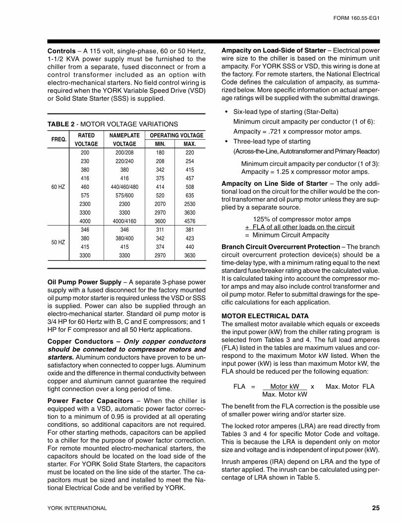
FORM 160.55-EG1
25YORK INTERNATIONAL
Controls – A 115 volt, single-phase, 60 or 50 Hertz,1-1/2 KVA power supply must be furnished to thechiller from a separate, fused disconnect or from acontrol transformer included as an option withelectro-mechanical starters. No field control wiring isrequired when the YORK Variable Speed Drive (VSD)or Solid State Starter (SSS) is supplied.
Oil Pump Power Supply – A separate 3-phase powersupply with a fused disconnect for the factory mountedoil pump motor starter is required unless the VSD or SSSis supplied. Power can also be supplied through anelectro-mechanical starter. Standard oil pump motor is3/4 HP for 60 Hertz with B, C and E compressors; and 1HP for F compressor and all 50 Hertz applications.
Copper Conductors – Only copper conductorsshould be connected to compressor motors andstarters. Aluminum conductors have proven to be un-satisfactory when connected to copper lugs. Aluminumoxide and the difference in thermal conductivity betweencopper and aluminum cannot guarantee the requiredtight connection over a long period of time.
Power Factor Capacitors – When the chiller isequipped with a VSD, automatic power factor correc-tion to a minimum of 0.95 is provided at all operatingconditions, so additional capacitors are not required.For other starting methods, capacitors can be appliedto a chiller for the purpose of power factor correction.For remote mounted electro-mechanical starters, thecapacitors should be located on the load side of thestarter. For YORK Solid State Starters, the capacitorsmust be located on the line side of the starter. The ca-pacitors must be sized and installed to meet the Na-tional Electrical Code and be verified by YORK.
Ampacity on Load-Side of Starter – Electrical powerwire size to the chiller is based on the minimum unitampacity. For YORK SSS or VSD, this wiring is done atthe factory. For remote starters, the National ElectricalCode defines the calculation of ampacity, as summa-rized below. More specific information on actual amper-age ratings will be supplied with the submittal drawings.
• Six-lead type of starting (Star-Delta)
Minimum circuit ampacity per conductor (1 of 6):
Ampacity = .721 x compressor motor amps.
• Three-lead type of starting
(Across-the-Line, Autotransformer and Primary Reactor)
Minimum circuit ampacity per conductor (1 of 3):Ampacity = 1.25 x compressor motor amps.
Ampacity on Line Side of Starter – The only addi-tional load on the circuit for the chiller would be the con-trol transformer and oil pump motor unless they are sup-plied by a separate source.
125% of compressor motor amps+ FLA of all other loads on the circuit= Minimum Circuit Ampacity
Branch Circuit Overcurrent Protection – The branchcircuit overcurrent protection device(s) should be atime-delay type, with a minimum rating equal to the nextstandard fuse/breaker rating above the calculated value.It is calculated taking into account the compressor mo-tor amps and may also include control transformer andoil pump motor. Refer to submittal drawings for the spe-cific calculations for each application.
MOTOR ELECTRICAL DATAThe smallest motor available which equals or exceedsthe input power (kW) from the chiller rating program isselected from Tables 3 and 4. The full load amperes(FLA) listed in the tables are maximum values and cor-respond to the maximum Motor kW listed. When theinput power (kW) is less than maximum Motor kW, theFLA should be reduced per the following equation:
FLA = Motor kW x Max. Motor FLAMax. Motor kW
The benefit from the FLA correction is the possible useof smaller power wiring and/or starter size.
The locked rotor amperes (LRA) are read directly fromTables 3 and 4 for specific Motor Code and voltage.This is because the LRA is dependent only on motorsize and voltage and is independent of input power (kW).
Inrush amperes (IRA) depend on LRA and the type ofstarter applied. The inrush can be calculated using per-centage of LRA shown in Table 5.
FREQ.RATED NAMEPLATE OPERATING VOLTAGE
VOLTAGE VOLTAGE MIN. MAX.200 200/208 180 220
230 220/240 208 254380 380 342 415416 416 375 457
60 HZ 460 440/460/480 414 508575 575/600 520 6352300 2300 2070 2530
3300 3300 2970 36304000 4000/4160 3600 4576346 346 311 381
380 380/400 342 42350 HZ
415 415 374 4403300 3300 2970 3630
TABLE 2 - MOTOR VOLTAGE VARIATIONS
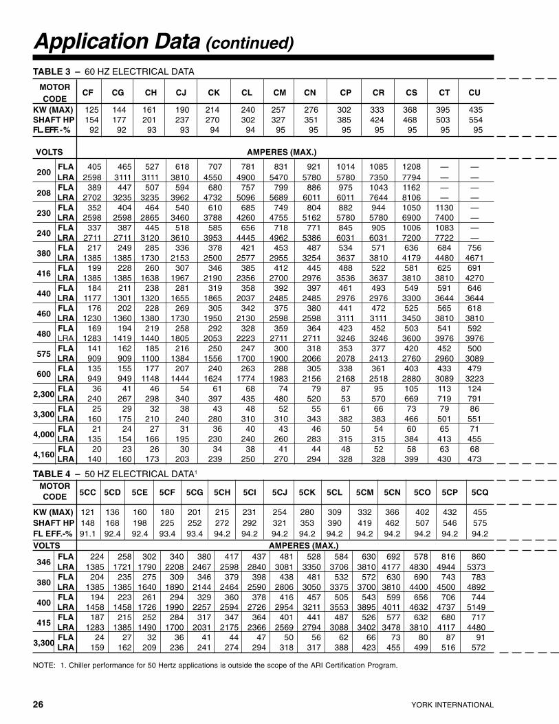
YORK INTERNATIONAL26
Application Data (continued)
NOTE: 1. Chiller performance for 50 Hertz applications is outside the scope of the ARI Certification Program.
TABLE 4 – 50 HZ ELECTRICAL DATA1
MOTOR5CC 5CD 5CE 5CF 5CG 5CH 5CI 5CJ 5CK 5CL 5CM 5CN 5CO 5CP 5CQCODE
KW (MAX) 121 136 160 180 201 215 231 254 280 309 332 366 402 432 455SHAFT HP 148 168 198 225 252 272 292 321 353 390 419 462 507 546 575FL EFF.-% 91.1 92.4 92.4 93.4 93.4 94.2 94.2 94.2 94.2 94.2 94.2 94.2 94.2 94.2 94.2VOLTS AMPERES (MAX.)
346FLA 224 258 302 340 380 417 437 481 528 584 630 692 578 816 860LRA 1385 1721 1790 2208 2467 2598 2840 3081 3350 3706 3810 4177 4830 4944 5373
380FLA 204 235 275 309 346 379 398 438 481 532 572 630 690 743 783LRA 1385 1385 1640 1890 2144 2464 2590 2806 3050 3375 3700 3810 4400 4500 4892
400FLA 194 223 261 294 329 360 378 416 457 505 543 599 656 706 744LRA 1458 1458 1726 1990 2257 2594 2726 2954 3211 3553 3895 4011 4632 4737 5149
415FLA 187 215 252 284 317 347 364 401 441 487 526 577 632 680 717LRA 1283 1385 1490 1700 2031 2175 2366 2569 2794 3088 3402 3478 3810 4117 4480
3,300FLA 24 27 32 36 41 44 47 50 56 62 66 73 80 87 91LRA 159 162 209 236 241 274 294 318 317 388 423 455 499 516 572
VOLTS AMPERES (MAX.)
200FLA 405 465 527 618 707 781 831 921 1014 1085 1208 — —LRA 2598 3111 3111 3810 4550 4900 5470 5780 5780 7350 7794 — —
208FLA 389 447 507 594 680 757 799 886 975 1043 1162 — —LRA 2702 3235 3235 3962 4732 5096 5689 6011 6011 7644 8106 — —
230FLA 352 404 464 540 610 685 749 804 882 944 1050 1130 —LRA 2598 2598 2865 3460 3788 4260 4755 5162 5780 5780 6900 7400 —
240FLA 337 387 445 518 585 656 718 771 845 905 1006 1083 —LRA 2711 2711 3120 3610 3953 4445 4962 5386 6031 6031 7200 7722 —
380FLA 217 249 285 336 378 421 453 487 534 571 636 684 756LRA 1385 1385 1730 2153 2500 2577 2955 3254 3637 3810 4179 4480 4671
416FLA 199 228 260 307 346 385 412 445 488 522 581 625 691LRA 1385 1385 1638 1967 2190 2356 2700 2976 3536 3637 3810 3810 4270
440FLA 184 211 238 281 319 358 392 397 461 493 549 591 646LRA 1177 1301 1320 1655 1865 2037 2485 2485 2976 2976 3300 3644 3644
460FLA 176 202 228 269 305 342 375 380 441 472 525 565 618LRA 1230 1360 1380 1730 1950 2130 2598 2598 3111 3111 3450 3810 3810
480FLA 169 194 219 258 292 328 359 364 423 452 503 541 592LRA 1283 1419 1440 1805 2053 2223 2711 2711 3246 3246 3600 3976 3976
575FLA 141 162 185 216 250 247 300 318 353 377 420 452 500LRA 909 909 1100 1384 1556 1700 1900 2066 2078 2413 2760 2960 3089
600FLA 135 155 177 207 240 263 288 305 338 361 403 433 479LRA 949 949 1148 1444 1624 1774 1983 2156 2168 2518 2880 3089 3223
2,300FLA 36 41 46 54 61 68 74 79 87 95 105 113 124LRA 240 267 298 340 397 435 480 520 53 570 669 719 791
3,300FLA 25 29 32 38 43 48 52 55 61 66 73 79 86LRA 160 175 210 240 280 310 310 343 382 383 466 501 551
4,000FLA 21 24 27 31 36 40 43 46 50 54 60 65 71LRA 135 154 166 195 230 240 260 283 315 315 384 413 455
4,160FLA 20 23 26 30 34 38 41 44 48 52 58 63 68LRA 140 160 173 203 239 250 270 294 328 328 399 430 473
TABLE 3 – 60 HZ ELECTRICAL DATA
MOTORCF CG CH CJ CK CL CM CN CP CR CS CT CU
CODEKW (MAX) 125 144 161 190 214 240 257 276 302 333 368 395 435SHAFT HP 154 177 201 237 270 302 327 351 385 424 468 503 554FL. EFF. - % 92 92 93 93 94 94 95 95 95 95 95 95 95

FORM 160.55-EG1
27YORK INTERNATIONAL
5CR 5CS 5CT 5CU 5CV MOTORCODE
481 518 554 591 630 KW(MAX.)608 658 704 750 800 SHAFT HP94.2 94.7 94.7 94.7 94.7 FL EFF.-%
909 982 1051 1107 1181 FLA3465780 5780 6615 6931 7356 LRA
841 895 957 1008 1075 FLA3805600 5491 5491 6313 6694 LRA
799 850 909 958 1021 FLA4005895 5780 5780 6645 7046 LRA
764 819 876 923 985 FLA4155130 5108 5512 5780 6131 LRA
96 103 110 116 124 FLA3,300614 644 693 725 744 LRA
AMPERES (MAX.) VOLTS
MOTORCV CW CX CY CZ CA CBCODE
478 514 542 578 617 660 703 KW (MAX.)608 655 690 740 790 845 900 SHAFT HP
95 95 95 95.5 95.5 95.5 95.5 FL EFF.-%
AMPERES (MAX.) VOLTS
— — — — — — — FLA200— — — — — — — LRA
— — — — — — — FLA208— — — — — — — LRA
— — — — — — — FLA230— — — — — — — LRA
— — — — — — — FLA240— — — — — — — LRA
817 879 942 997 1065 1126 1200 FLA3805326 5780 6782 5780 6644 7106 7513 LRA
747 810 860 911 973 1029 1096 FLA4164869 5640 5780 5694 6069 6489 6863 LRA
706 579 813 861 920 973 1036 FLA4404209 4783 5367 4783 5249 5529 5529 LRA
675 726 778 824 880 931 991 FLA4604400 5000 5600 5000 5488 5780 5780 LRA
647 696 746 790 843 892 950 FLA4804591 5217 5843 5217 5727 6031 6031 LRA
540 581 622 659 704 744 793 FLA5753550 4039 4440 4300 4200 4694 4963 LRA
518 557 596 632 675 713 760 FLA6003704 4215 4633 4484 4383 4898 5179 LRA
135 146 154 165 176 186 198 FLA2,300867 935 960 1008 1100 1172 1244 LRA
94 102 108 115 123 130 138 FLA3,300576 652 682 719 744 744 863 LRA
78 84 89 95 101 107 114 FLA4,000499 538 540 554 631 674 713 LRA
75 81 85 91 97 103 110 FLA4,160519 560 562 576 656 701 742 LRA

YORK INTERNATIONAL28
TYPE SOLID STAR ACROSSSTARTER STATE
DELTAAUTO TRANSFORMER
THE LINEPRIMARY REACTOR
STARTER
VOLTAGE LOW LOW LOW LOW/HIGH LOW/HIGH LOW/HIGH HIGH HIGH60 HZ 460, 575 200-600 200-600 200-4160 200-4160 200-4160 2300-4160 2300-4160
50 HZ 380-415 346-415 346-415 346-3300 346-3300 346-3300 2300-3300 2300-3300TRANSITION — CLOSED CLOSED CLOSED CLOSED — CLOSED CLOSED
% TAP — — 57.7 65 80 — 65 80
INRUSH 45 33 33 42.3 64 100 65 80AS A % OF LRA
TABLE 5 – MOTOR STARTERS
NOTE: Inrush less than 100% of full load amps (FLA).
COMPRESSOREVAPORATOR CONDENSER
MOTOR CODESCODE 60 HZ 50 HZ
B1, B2 G0, G1, G3 A1, A2, A3, A4 CF Thru CN 5CC Thru 5CLG1, G3 A1, A2, A3, A4
C1, C2, C3 H1, H3 A1, A2, A3, A4, B1, B2, B3, B4CK Thru CP 5CG Thru 5CL
J1, J3 A1, A2, A3, A4, B1, B2, B3, B4K1, K3 B1, B2, B3, B4G1, G3 A1, A2, A3, A4
H1, H3 A1, A2, A3, A4, C1, C2, C3, C4
E1, E2, E3 J1, J3 A1, A2, A3, A4, C1, C2, C3, C4 CN Thru CX 5CK Thru 5CRK1, K3 C1, C2, C3, C4, D1, D2, D3, D4
L1, L3 C1, C2, C3, C4, D1, D2, D3, D4F1 K4, K6, K7, K9 C5, C6, C7, C8, D5, D6, D7, D8 CS Thru CZ
5CN Thru 5CVF2 L4, L6 C5, C6, C7, C8, D5, D6, D7, D8 CA Thru CB
TABLE 6 – AVAILABLE COMPRESSOR/SHELL/MOTOR COMBINATIONS
Application Data (continued)

FORM 160.55-EG1
29YORK INTERNATIONAL
00613VIP

YORK INTERNATIONAL30
Dimensions (Ft. - In.)
NOTES:
1. All dimensions are approximate. Certified dimensions are available on request.
2. For compact water boxes (shown above), determine overall unit length by adding water box depth to tube sheet length. For marine waterboxes, refer to pages 36-37.
3. Water nozzles can be located on either end of unit. Add 1/2" to nozzle length for flanged connections.
4. To determine overall installed height, add 7/8" for isolators.
5. A doorway or other properly located opening may be used for tube removal.
LD07260
LD07224

FORM 160.55-EG1
31YORK INTERNATIONAL
F COMPRESSORSEVAPORATOR – CONDENSER CODES
DIM. K-C K-D L-C L-DA 6' 10-1/2" 7' 4" 7' 0-1/2" 7' 6"B 15' 0" 15' 0" 15' 0" 15' 0"C 9' 10" 10' 2-1/2" 9' 10" 10' 2-1/2"D 1' 6-1/2" 1' 9-1/4" 1' 6-1/2" 1' 9-1/4"E 1' 10-3/4" 1' 10-3/4" 1' 11-3/4" 1' 11-3/4"
E COMPRESSORSEVAPORATOR – CONDENSER CODES
DIM. G-A H-A H-C J-A J-C K-C K-D L-C L-DA 5' 7-3/4" 5' 10-1/2" 6' 3-1/2" 6' 1-1/2" 6' 6-1/2" 6' 10-1/2" 7' 4" 7' 0-1/2" 7' 6"B 13' 0" 13' 0" 13' 0" 13' 0" 13' 0" 13' 0" 13' 0" 13' 0" 13' 0"C 9' 0-1/8" 9' 0-1/8" 9' 5-3/8" 9' 0-1/8" 9' 5-3/8" 9' 5-3/8" 9' 6-1/8" 9' 5-3/8" 9' 6-1/8"D 1' 4" 1' 4" 1' 6-1/2" 1' 4" 1' 6-1/2" 1' 6-1/2" 1' 9-1/4" 1' 6-1/2" 1' 9-1/4"E 1' 5-7/8" 1' 7-1/4" 1' 7-1/4" 1' 8-3/4" 1' 8-3/4" 1' 10-3/4" 1' 10-3/4" 1' 11-3/4" 1' 11-3/4"
C COMPRESSORSEVAPORATOR – CONDENSER CODES
DIM. G-A H-A H-B J-A J-13 K-BA 5' 7-3/4" 5' 10-1/2" 6' 3-1/2" 6' 1-1/2" 6' 6-1/2" 6' 10-1/2"B 13' 0" 13' 0" 13' 0" 13' 0" 13' 0" 13' 0"C 8' 1-1/4" 8' 1-1/4" 8' 4-3/4" 8' 1-1/4" 8' 4-3/4" 8' 4-3/4"D 1' 4" 1' 4" 1' 6-1/2" 1' 4" 1' 6-1/2" 1' 6-1/2"E 1' 5-7/8" 1' 7-1/4" 1' 7-1/4" 1' 8-3/4" 1' 8-3/4" 1' 10-3/4"
B COMPRESSOREVAPORATOR – CONDENSER SHELL
DIM. G-AA 5' 7-3/4"B 13' 0"C 7' 6-1/8"D 1' 4"E 1' 5-7/8"

YORK INTERNATIONAL32
Dimensions (mm)
NOTES:
1. All dimensions are approximate. Certified dimensions are available on request.
2. For compact water boxes (shown above), determine overall unit length by adding water box depth to tube sheet length. For marine waterboxes, refer to pages 40-41.
3. Water nozzles can be located on either end of unit. Add 12 mm to nozzle length for flanged connections.
4. To determine overall installed height, add 22 mm for isolators.
5. A doorway or other properly located opening may be used for tube removal.
LD07226
LD07225
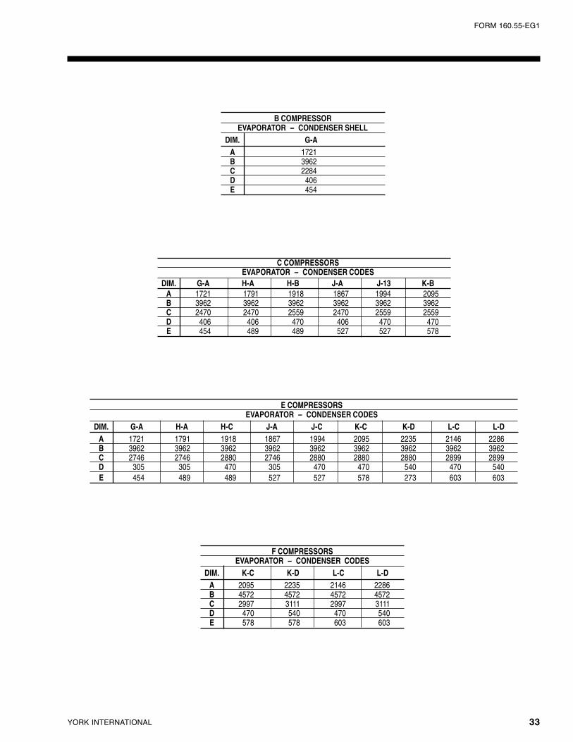
FORM 160.55-EG1
33YORK INTERNATIONAL
F COMPRESSORSEVAPORATOR – CONDENSER CODES
DIM. K-C K-D L-C L-DA 2095 2235 2146 2286B 4572 4572 4572 4572C 2997 3111 2997 3111D 470 540 470 540E 578 578 603 603
E COMPRESSORSEVAPORATOR – CONDENSER CODES
DIM. G-A H-A H-C J-A J-C K-C K-D L-C L-DA 1721 1791 1918 1867 1994 2095 2235 2146 2286B 3962 3962 3962 3962 3962 3962 3962 3962 3962C 2746 2746 2880 2746 2880 2880 2880 2899 2899D 305 305 470 305 470 470 540 470 540E 454 489 489 527 527 578 273 603 603
C COMPRESSORSEVAPORATOR – CONDENSER CODES
DIM. G-A H-A H-B J-A J-13 K-BA 1721 1791 1918 1867 1994 2095B 3962 3962 3962 3962 3962 3962C 2470 2470 2559 2470 2559 2559D 406 406 470 406 470 470E 454 489 489 527 527 578
B COMPRESSOREVAPORATOR – CONDENSER SHELL
DIM. G-AA 1721B 3962C 2284D 406E 454

YORK INTERNATIONAL34
Dimensions (Ft. - In.) – Nozzle Arrangements
NOTES:1 . Standard water nozzles are furnished as welding stub-outs with Victaulic grooves, allowing the option of welding, flanges, or use of
Victaulic couplings. Factory installed, class 150 (ANSI B16.5, round slip-on, forged carbon steel with 1/16" raised face), water flangednozzles are optional. Companion flanges, nuts, bolts and gaskets are not furnished.
2. Add 7/8" for isolators as shown.3. One, two and three pass nozzle arrangements are available only in pairs shown and for all shell codes. Any pair of evaporator nozzles may
be used in combination with any pair of condenser nozzles.4. Evaporator and condenser water must enter the water box through the bottom connection to achieve rated performance.5. Connected piping should allow for removal of compact water boxes for tube access and cleaning.
EVAPORATORS – COMPACT WATER BOXES
LD07227
NOZZLEARRANGEMENTS
NO. OF EVAPORATORPASSES IN-OUT
1A-HH-A
NOZZLEARRANGEMENTS
NO. OF EVAPORATORPASSES IN-OUT
2
E-B
D-CM-JL-K
NOZZLEARRANGEMENTS
NO. OF EVAPORATORPASSES IN-OUT
3P-FG-N
EVAP. NOZZLE PIPE SIZEEVAPORATOR
SHELL NO. OF PASSESNOZZLE DIMENSIONS
CODEGG JJ HH KK
1 2 3 1-PASS 2-PASS 3-PASS 2-PASS 3-PASS 2-PASSG 10" 8" 6" 11-1/2" 1' 2-3/8" 1' 3-1/2" 8-5/8" 7-1/2" 8-3/4"H 12" 8" 6" 1' 0-5/8" 1' 3-3/8" 1' 4-5/8" 9-7/8" 8-5/8" 10"
J 14" 10" 8" 1' 1-3/8" 1' 5-1/8" 1' 6-1/4" 9-5/8" 8-1/2" 9"K 14" 10" 8" 1' 3-1/8" 1' 6-1/8" 1' 7-1/8" 1' 0-1/8" 11-1/8" 10"L 16" 12" 10" 1' 4-7/8" 1' 7-7/8" 1' 8-7/8" 1' 1-7/8" 1' 0-7/8" 10-1/2"

FORM 160.55-EG1
35YORK INTERNATIONAL
NOTES: See page 34.
One and Two Pass Nozzle Arrangements are available only in pairs shown and for all shell codes. Any pair of evaporator nozzles maybeused in combination with any pair of condenser nozzles.
CONDENSERS – COMPACT WATER BOXES
LD07228
NOZZLEARRANGEMENTS*
NO. OF EVAPORATORPASSES IN-OUT
1P-QQ-P
NOZZLEARRANGEMENTS*
NO. OF EVAPORATORPASSES IN-OUT
2R-ST-U
CONDENSER NOZZLE PIPE SIZECONDENSER
SHELLNOZZLE DIMENSIONS
CODENO. OF PASSES
NNPP RR
1 2 2-PASS 2-PASSA 12" 8" 2’ 3-1/2" 1’ 8-1/2" 2’ 10-1/2"B 14" 10" 2’ 3-1/4" 1’ 7" 2’ 11-1/2"
C 14" 10" 2’ 3-1/4" 1’ 7" 12’ 11-1/2"D 16" 12" 2’ 7-5/8" 1’ 9-3/4" 3’ 5-1/2"

YORK INTERNATIONAL36
EVAPORATORS – MARINE WATER BOXES
LD05364
EVAP. E F G HSHELL A C DCODE
1-PASS 2-PASS 3-PASS 1-PASS 2-PASS 3-PASS 1-PASS 2-PASS 3-PASS BackHead
G 2' 0-3/8" 6" 2' 4-5/8" 10-1/8" 9" 8" 9-1/4" 8-1/4" 7-1/4" 1' 7-5/8" 1' 5-5/8" 1' 3-5/8" 5-3/8"H 2' 2-1/8" 4-1/2" 2' 5-3/4" 1' 0-5/8" 10-1/8" 9-1/8" 10-1/2" 8-1/4" 7-1/4" 1' 10-1/8" 1' 5-5/8" 1' 3-5/8" 5-3/8"J 2' 3-3/8" 11" 2' 8-1/2" 11" 10" 9" 10-1/2" 9-1/4" 8-1/4" 1' 10-3/8" 1' 7-7/8" 1' 5-7/8" 5-3/8"
K 2' 5-5/8" 1' 0-1/2" 2' 10" 1' 1-1/8" 1' 0-1-1/8" 11-1/8'' 10-1/2" 9-1/4" 8-1/4' 1' 10-3/8" 1' 7-7/8" 1' 5-7/8" 6-1/2"L 2' 6" 9" 3' 0-7/8" 1' 2-3/8" 11-518" 10-5/8" 11" 11" 9-3/4" 1' 11-5/8" 1' 11-5/8" 1' 9-1/8" 6-3/4"
Dimensions (Ft. - In.) – Nozzle Arrangements

FORM 160.55-EG1
37YORK INTERNATIONAL
CONDENSERS – MARINE WATER BOXES
LD05365
CONDENSERSHELL D E F
G H
CODE1-PASS 2-PASS 1-PASS 2-PASS
2-PASS
A 4' 2-1/4" 1' 10-3/4" 1' 10-5/8" 11-1/8" 8-5/8" 1' 11-5/8" 1' 6-5/8" 5-1/2"
B 4' 4-1/2" 2' 1-1/4" 1' 9-1/4" 1' 0-1/8" 9-5/8" 2' 1 -7/8" 1' 8-7/8" 5-3/4"C 4' 4-1/2" 2' 1-1/4" 1' 9-1/4" 1' 0-1/8" 9-5/8" 2' 1-7/8" 1' 8-7/8" 5-3/4"D 4' 11-5/8" 2' 4" 1' 11-3/4" 1' 0-1/4" 11-1/4" 2' 2-3/8" 2' 0-3/4" 6"
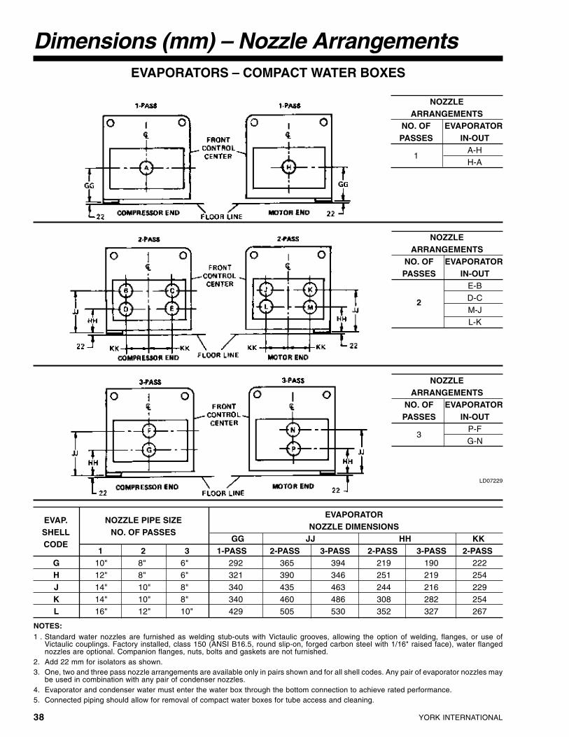
YORK INTERNATIONAL38
Dimensions (mm) – Nozzle ArrangementsEVAPORATORS – COMPACT WATER BOXES
LD07229
NOTES:1 . Standard water nozzles are furnished as welding stub-outs with Victaulic grooves, allowing the option of welding, flanges, or use of
Victaulic couplings. Factory installed, class 150 (ANSI B16.5, round slip-on, forged carbon steel with 1/16" raised face), water flangednozzles are optional. Companion flanges, nuts, bolts and gaskets are not furnished.
2. Add 22 mm for isolators as shown.3. One, two and three pass nozzle arrangements are available only in pairs shown and for all shell codes. Any pair of evaporator nozzles may
be used in combination with any pair of condenser nozzles.4. Evaporator and condenser water must enter the water box through the bottom connection to achieve rated performance.5. Connected piping should allow for removal of compact water boxes for tube access and cleaning.
NOZZLEARRANGEMENTS
NO. OF EVAPORATORPASSES IN-OUT
1A-HH-A
NOZZLEARRANGEMENTS
NO. OF EVAPORATORPASSES IN-OUT
3P-FG-N
EVAP. NOZZLE PIPE SIZEEVAPORATOR
SHELL NO. OF PASSESNOZZLE DIMENSIONS
CODEGG JJ HH KK
1 2 3 1-PASS 2-PASS 3-PASS 2-PASS 3-PASS 2-PASSG 10" 8" 6" 292 365 394 219 190 222H 12" 8" 6" 321 390 346 251 219 254
J 14" 10" 8" 340 435 463 244 216 229K 14" 10" 8" 340 460 486 308 282 254L 16" 12" 10" 429 505 530 352 327 267
NOZZLEARRANGEMENTS
NO. OF EVAPORATORPASSES IN-OUT
2
E-B
D-CM-JL-K

FORM 160.55-EG1
39YORK INTERNATIONAL
CONDENSERS – COMPACT WATER BOXES
LD07230
NOTES: See page 38.
One and Two Pass Nozzle Arrangements are available only in pairs shown and for all shell codes. Any pair of evaporator nozzles maybeused in combination with any pair of condenser nozzles.
NOZZLEARRANGEMENTS*
NO. OF EVAPORATORPASSES IN-OUT
1P-QQ-P
NOZZLEARRANGEMENTS*
NO. OF EVAPORATORPASSES IN-OUT
2R-ST-U
CONDENSER NOZZLE PIPE SIZECONDENSER
SHELLNOZZLE DIMENSIONS
CODENO. OF PASSES
NNPP RR
1 2 2-PASS 2-PASSA 12" 8" 698 521 876B 14" 10" 692 483 902
C 14" 10" 692 483 902D 16" 12" 803 552 1054
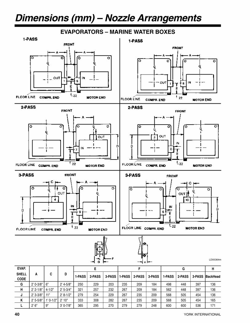
YORK INTERNATIONAL40
Dimensions (mm) – Nozzle ArrangementsEVAPORATORS – MARINE WATER BOXES
LD05364m
EVAP. E F G HSHELL A C DCODE
1-PASS 2-PASS 3-PASS 1-PASS 2-PASS 3-PASS 1-PASS 2-PASS 3-PASS BackHead
G 2' 0-3/8" 6" 2' 4-5/8" 250 229 203 235 209 184 498 448 397 136H 2' 2-1/8" 4-1/2" 2' 5-3/4" 321 257 232 267 209 184 562 448 397 136J 2' 3-3/8" 11" 2' 8-1/2" 279 254 229 267 235 209 568 505 454 136
K 2' 5-5/8" 1' 0-1/2" 2' 10" 333 308 282 267 235 209 568 505 454 165L 2' 6" 9" 3' 0-7/8" 365 295 270 279 279 248 600 600 536 171
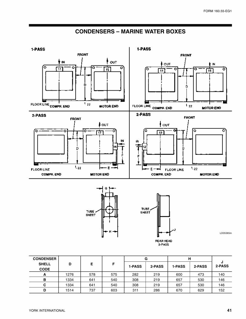
FORM 160.55-EG1
41YORK INTERNATIONAL
CONDENSERS – MARINE WATER BOXES
LD05365m
CONDENSERSHELL D E F
G HJ
CODE1-PASS 2-PASS 1-PASS 2-PASS 2-PASS
A 1276 578 575 282 219 600 473 140
B 1334 641 540 308 219 657 530 146C 1334 641 540 308 219 657 530 146D 1514 737 603 311 286 670 629 152

YORK INTERNATIONAL42
Weights – Lbs.
NOTES:
1. Shipping weights are for a unit including Control Center but DONOT include weight of motor, refrigerant, thermal insulation,marine water boxes or shipping skids. See Table 11 for motorweights. See Form 160.55-PA1 for other additional weights.
2. Operating weights shown include unit (less motor weight), Con-trol Center, oil, water, refrigerant operating charge and factoryinsulation of evaporator. Add motor weights per Table 11.
3. Loading per isolator equals operating weight divided by 4.
4. If optional marine type water boxes are furnished, increase unitweights per Form 160.55-PA1.
SHELL REFRIGERANT CHILLER CHILLERCODES CHARGE (LBS.) SHIPPING (LBS.) OPERATING (LBS.)G0A1 890 11,090 13,015G0A2 890 11,250 13,230G0A3 890 11,435 13,480
G0A4 890 11,645 13,770G1A1 890 11,238 13,220G1A2 890 11,394 13,430
G1A3 890 11,578 13,680G1A4 890 11,792 13,970G3A1 890 11,536 13,630
G3A2 890 11,692 13,840G3A3 890 11,876 14,090G3A4 890 12,090 14,380
TABLE 7 – CHILLER WEIGHTS (LESS MOTOR)B COMPRESSOR
SHELL REFRIGERANT CHILLER CHILLERCODES CHARGE (LBS.) SHIPPING (LBS.) OPERATING (LBS.)G1A1 890 11,815 13,795G1A2 890 11,970 14,010G1A3 890 12,155 14,260
G1A4 890 12,370 14,540G3A1 890 12,112 14,205G3A2 890 12,248 14,400
G3A3 890 12,452 14,665G3A4 890 12,665 14,955H1A1 970 12,590 14,810
H1A2 970 12,745 15,020H1A3 970 12,930 15,270H1A4 970 13,145 15,560
H3A1 970 12,850 15,170H3A2 970 12,990 15,365H3A3 970 13,190 15,630
H3A4 970 13.410 15,925H1B1 970 14,276 16,780H1B2 970 14,496 17,075
H1B3 970 14,740 17,410H1B4 970 15,020 17,790H3B1 970 14,540 17,145
H3B2 970 14,755 17,440H3B3 970 15,000 17,770H3B4 970 15.282 18,150
J1A1 1,130 13,110 15,485J1A2 1,130 13,250 15,840J1A3 1,130 13,450 15,945
J1A4 1,130 13,665 16,395J3A1 1,130 13,465 16,130J3A2 1,130 13,600 16,320
J3A3 1,130 13,805 16,590J3A4 1,130 14.020 16,880J1B1 1,130 14,796 17,620
J1B2 1,130 15,015 17,915J1B3 1,130 15,260 18,245J1B4 1,130 15,540 18,625
J3B1 1,130 15,150 18,100J3B2 1,130 15,368 18,400J3B3 1,130 15,615 18,730
J3B4 1,130 15,895 19,110K1B1 1,270 16,715 20,040K1B2 1,270 16,935 20,335
K1B3 1,270 17,180 20,670K1B4 1,270 17,460 21,050K3B1 1,270 17,145 20,630
K3B2 1,270 17,362 20,925K3B3 1,270 17,610 21,260K3B4 1,270 1 7890 21,640
TABLE 8 – CHILLER WEIGHTS (LESS MOTOR)C COMPRESSOR

FORM 160.55-EG1
43YORK INTERNATIONAL
Weights – Lbs.
TABLE 10 – CHILLER WEIGHTS (LESS MOTOR)F COMPRESSOR
TABLE 9 – CHILLER WEIGHTS (LESS MOTOR)E COMPRESSOR
SHELL REFRIGERANT CHILLER CHILLERCODES CHARGE (LBS.) SHIPPING (LBS.) OPERATING (LBS.)G1A1 890 14,880 16,860G1A2 890 15,035 17,070G1A3 890 15,220 17,325G1A4 890 15,415 17,595G3A1 890 15,210 17,305G3A2 890 15,365 17,515G3A3 890 15,550 17,765G3A4 890 15,745 18,035H1A1 970 15,550 17,765H1A2 970 15,710 17,985H1A3 970 15,890 18,230H1A4 970 16,085 18,500H3C1 970 15,810 18,125H3C2 970 15,965 18,340H3C3 970 16,150 18,590H3C4 970 16,345 18,860H1C1 970 17,590 20,140H1C2 970 17,810 20,440H1C3 970 18,055 20,775H1C4 970 18,335 21,155H3C1 970 17,850 20,500H3C2 970 18,070 20,800H3C3 970 18,316 21,135H3C4 970 18,595 21,515J1A1 1,130 16,460 18,995J1A2 1,130 16,616 19,205J1A3 1,130 16,800 19,455J1A4 1,130 16,995 19,725J3A1 1,130 16,805 19,470J3A2 1,130 16,960 19,680J3A3 1,130 17,145 19,930J3A4 1,130 17,340 20,200J1C1 1,130 18,512 21,380J1C2 1,130 18,730 21,675J1C3 1,130 18,976 22,010J1C4 1.130 19.255 22,390J3C1 1,130 18,860 21,860J3C2 1,130 19,075 22,150J3C3 1,130 19,322 22,490J3C4 1,130 19,600 22.865K1C1 1,270 20,075 23,445K1C2 1,270 20,290 23,740K1C3 1,270 20,540 24,075K1C4 1,270 20,815 24,450K3C1 1,270 20,500 24,030K3C2 1,270 20,720 24,330K3C3 1,270 20,965 24,665K3C4 1,270 21,245 25,045K1D1 1,270 22,085 25,830K1D2 1,270 22,435 26,310K1D3 1,270 22,825 26,840K1D4 1,270 23,270 27,440K3D1 1,270 22,510 26,420K3D2 1,270 22,861 26,895K3D3 1,270 23,253 27,430K3D4 1,270 23,700 28,035L1C1 1,390 21,175 24,800L1C2 1,390 21,395 25,220L1C3 1,390 21,640 25,550L1C4 1.390 21,919 25,930L3C1 1,390 21,700 25,650L3C2 1,390 21,920 25,950L1C3 1,390 22,165 26,285L1C4 1,390 22,443 26,660L1D1 1,390 23,180 27,300L1D2 1,390 23,530 27,780L1D3 1,390 23,921 28,310L1D4 1,390 24,365 28,915L3D1 1,390 23,700 28,030L3D2 1,390 24,060 28,515L3D3 1,390 24,450 29,045L3D4 1,390 24,890 29,645
NOTE:
1. Motor weight shown in Table 11 is typical of 200 thru 600 voltmotors; high voltage motors may be heavier – contact YORK.
TABLE 11 – MOTOR WEIGHTS - LBS.60 HZ 50 HZ
MOTORTYPICAL
MOTORTYPICAL
MOTORTYPICAL
MOTOR TYPICAL
CODE MOTOR
CODEMOTOR
CODEMOTOR
CODEMOTOR
WEIGHT WEIGHT WEIGHT WEIGHTCF 940 CU 2,635 5CC 940 5CO 2,635CG 940 CV 2,635 5CD 940 5CP 2,930CH 940 CW 2,930 5CE 940 5CQ 2,930CJ 940 CX 2,930 5CF 1,440 5CR 2,930CK 1,440 CY 2,930 5CG 1,440 5CS 2,930CL 1,440 CZ 2,930 5CH 1,700 5CT 5,750CM 1,700 CA 5,750 5CI 1,700 5CU 5,750CN 1,700 CB 5,750 5CJ 1,700 5CV 5,750CP 1,700 5CK 1,700CR 1,700 5CL 2,635CS 2,635 5CM 2,635CT 2,635 5CN 2,635
SHELL REFRIGERANT CHILLER CHILLERCODES CHARGE (LBS.) SHIPPING (LBS.) OPERATING (LBS.)K4C5 1,390 22,190 26,845K4C6 1,390 22,440 26,185K4C7 1,390 22,725 26,685K4C8 1,390 23,050 27,010K6C5 1,390 22,535 26,335K6C6 1,390 22,790 26,680K6C7 1,390 23,075 27,066K6C8 1,390 23,400 27,505K7C5 1,530 22,840 26,720K7C6 1,530 23,095 27,065K7C7 1,530 23,380 27,450K7C8 1,530 23,700 27,885K9C5 1,530 23,340 27,415K9C6 1,530 23,595 27,760K9C7 1,530 23,880 28,145K9C8 1.530 24,200 28,580K4D5 1,390 24,476 28,565K4D6 1,390 24,880 29,115K4D7 1,390 25,340 29,400K4D8 1,390 25,850 30,430K6D5 1,390 24,825 29,060K6D6 1,390 25,225 29,600K6D7 1,390 25,680 30,220K6D8 1,390 26,200 30,925K7D5 1,530 25,130 29,445K7D6 1,530 25,530 29,990K7D7 1,530 25,990 30,610K7D8 1,530 26,850 31,655K9D5 1,530 25,630 30,140K9D6 1,530 26,037 30,690K9D7 1,530 26,490 31,305K9D8 1,530 27,000 32,000L4C5 1,590 24,114 28,355L4C6 1,590 24,340 28,670L4C7 1,590 24,655 28,780L4C8 1,590 24,980 29,525L6C5 1,590 24,715 29,190L6C6 1,590 24,970 29,540L6C7 1,590 25,255 29,925L6C8 1,590 25,580 30,365L4D5 1,590 26,345 31,020L4D6 1,590 26,750 31,570L4D7 1,590 27,200 32,180L4D8 1,590 27,720 32,885L6D5 1,590 26,945 31,860L6D6 1,590 27,350 32,410L6D7 1,590 27,800 33,020L6D8 1,590 28,320 33,722

YORK INTERNATIONAL44
NOTES:
1. Shipping weights are for a unit including Control Center but DONOT include weight of motor, refrigerant, thermal insulation,marine water boxes or shipping skids. See Table 11A for motorweights. See Form 160.55-PA1 for other additional weights.
2. Operating weights shown include unit (less motor weight), Con-trol Center, oil, water, refrigerant operating charge and factoryinsulation of evaporator. Add motor weights per Table 11A.
3. Loading per isolator equals operating weight divided by 4.
4. If optional marine type water boxes are furnished, increase unitweights per Form 160.55-PA1.
SHELL REFRIGERANT CHILLER CHILLERCODES CHARGE (Kg) SHIPPING (Kg) OPERATING (Kg)G0A1 404 5030 5404G0A2 404 5103 6001
G0A3 404 5187 6114G0A4 404 5282 6246G1A1 404 5097 5996
G1A2 404 5168 6092G1A3 404 5252 6205G1A4 404 5349 6337
G3A1 404 5233 6182G3A2 404 5303 6281G3A3 404 5387 6391
G3A4 404 5484 6523
TABLE 7A – CHILLER WEIGHTS (LESS MOTOR)B COMPRESSOR
Weights – Kg
SHELL REFRIGERANT CHILLER CHILLERCODES CHARGE (Kg) SHIPPING (Kg) OPERATING (Kg)G1A1 404 5360 6257G1A2 404 5429 6355G1A3 404 5513 6468
G1A4 404 5611 6595G3A1 404 5494 6443G3A2 404 5556 6532
G3A3 404 5648 6652G3A4 404 5745 6783H1A1 440 5711 6718
H1A2 440 5781 6813H1A3 440 5865 6926H1A4 440 5962 7058
H3A1 440 5829 6881H3A2 440 5892 6969H3A3 440 5983 7089
H3A4 440 6083 7223H1B1 440 6475 7611H1B2 440 6575 7745
H1B3 440 6686 7897H1B4 440 6813 8069H3B1 440 6595 7777
H3B2 440 6693 7911H3B3 440 6804 8060H3B4 440 6932 8238
J1A1 512 5947 7024J1A2 512 6010 7185J1A3 512 6101 7233
J1A4 512 6198 7437J3A1 512 6108 7316J3A2 512 6169 7403
J3A3 512 6262 7525J3A4 512 6359 7657J1B1 512 6711 7992
J1B2 512 6811 8126J1B3 512 6922 8276J1B4 512 7049 8448
J3B1 512 6872 8210J3B2 512 6971 8346J3B3 512 7083 8496
J3B4 512 7210 8668K1B1 576 7582 9090K1B2 576 7682 9224
K1B3 576 7793 9376K1B4 576 7920 9548K3B1 576 7777 9358
K3B2 576 7875 9491K3B3 576 7988 9643K3B4 576 8115 9816
TABLE 8A – CHILLER WEIGHTS (LESS MOTOR)C COMPRESSOR
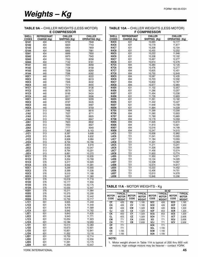
FORM 160.55-EG1
45YORK INTERNATIONAL
Weights – Kg
TABLE 10A – CHILLER WEIGHTS (LESS MOTOR)F COMPRESSOR
TABLE 9A – CHILLER WEIGHTS (LESS MOTOR)E COMPRESSOR
SHELL REFRIGERANT CHILLER CHILLERCODES CHARGE (Kg) SHIPPING (Kg) OPERATING (Kg)G1A1 404 6750 7648G1A2 404 6820 7743G1A3 404 6904 7859G1A4 404 6992 7981G3A1 404 6899 7850G3A2 404 6970 7945G3A3 404 7053 8058G3A4 404 7142 8181H1A1 440 7053 8058H1A2 440 7126 8158H1A3 440 7208 8269H1A4 440 7296 8392H3C1 440 7171 8222H3C2 440 7242 8319H3C3 440 7326 8432H3C4 440 7414 8555H1C1 440 7979 9136H1C2 440 8079 9272H1C3 440 8190 9424H1C4 440 8317 9596H3C1 440 8097 9299H3C2 440 8197 9435H3C3 440 8308 9587H3C4 440 8435 9759J1A1 513 7466 8616J1A2 513 7537 8711J1A3 513 7620 8825J1A4 513 7709 8947J3A1 513 7623 8832J3A2 513 7693 8927J3A3 513 7777 9040J3A4 513 7,865 9,163J1C1 513 8,397 9,698J1C2 513 8,496 9,832J1C3 513 8,608 9,984J1C4 513 8,734 10,156J3C1 513 8,555 9,916J3C2 513 8,652 10,047J3C3 513 8,764 10,201J3C4 513 8,891 10,372K1C1 576 9,106 10,635K1C2 576 9,204 10,768K1C3 576 9,317 10,920K1C4 576 9,442 11,091K3C1 576 9,299 10,900K3C2 576 9,399 11,036K3C3 576 9,510 11,188K3C4 576 9,637 11,360K1D1 576 10,018 11,716K1D2 576 10,177 11,934K1D3 576 10,353 12,175K1D4 576 10,555 12,447K3D1 576 10,211 11,984K3D2 576 10,370 12,200K3D3 576 10,548 12,442K3D4 576 10,750 12,717L1C1 631 9,605 11,249L1C2 631 9,705 11,440L1C3 631 9,816 11,589L1C4 631 9,942 11,762L3C1 631 9,843 11,635L3C2 631 9,943 11,771L1C3 631 10,054 11,923L1C4 631 10,180 12,093L1D1 631 10,514 12,383L1D2 631 10,673 12,601L1D3 631 10,851 12,841L1D4 631 11,052 13,116L3D1 631 10,750 12,714L3D2 631 10,914 12,934L3D3 631 11,091 13,175L3D4 631 11,290 13,447
TABLE 11A - MOTOR WEIGHTS - Kg
NOTE:
1. Motor weight shown in Table 11A is typical of 200 thru 600 voltmotors; high voltage motors may be heavier – contact YORK.
60 HZ 50 HZ
MOTORTYPICAL
MOTORTYPICAL
MOTORTYPICAL
MOTOR TYPICAL
CODE MOTOR
CODEMOTOR
CODEMOTOR
CODEMOTOR
WEIGHT WEIGHT WEIGHT WEIGHTCF 426 CU 1,195 5CC 426 5CO 1,195CG 426 CV 1,195 5CD 426 5CP 1,329CH 426 CW 1,329 5CE 426 5CQ 1,329CJ 426 CX 1,329 5CF 653 5CR 1,329CK 653 CY 1,329 5CG 653 5CS 1,329CL 653 CZ 1,329 5CH 771 5CT 2,608CM 771 CA 2,608 5CI 771 5CU 2,608CN 771 CB 2,608 5CJ 771 5CV 2,608CP 771 5CK 771CR 771 5CL 1,195CS 1,195 5CM 1,195CT 1,195 5CN 1,195
SHELL REFRIGERANT CHILLER CHILLERCODES CHARGE (Kg) SHIPPING (Kg) OPERATING (Kg)K4C5 631 10,065 12,177K4C6 631 10,179 11,877K4C7 631 10,308 12,104K4C8 631 10,455 12,252K6C5 631 10,222 11,946K6C6 631 10,338 12,102K6C7 631 10,467 12,277K6C8 631 10,614 12,476K7C5 694 10,360 12,120K7C6 694 10,476 12,277K7C7 694 10,605 12,451K7C8 694 10,750 12,649K9C5 694 10,587 12,435K9C6 694 10,703 12,592K9C7 694 10,832 12,767K9C8 694 10,977 12,964K4D5 631 11,102 12,957K4D6 631 11,286 13,207K4D7 631 11,494 13,336K4D8 631 11,726 13,803K6D5 631 11,261 13,182K6D6 631 11,442 13,427K6D7 631 11,648 13,708K6D8 631 11,884 14,028K7D5 694 11,399 13,356K7D6 694 11,580 13,603K7D7 694 11,789 13,885K7D8 694 12,179 14,359K9D5 694 11,626 13,672K9D6 694 11,810 13,921K9D7 694 12,016 14,199K9D8 694 12,247 14,515L4C5 721 10,938 12,862L4C6 721 11,041 13,005L4C7 721 11,184 13,055L4C8 721 11,331 13,393L6C5 721 11,211 13,241L6C6 721 11,326 13,399L6C7 721 11,456 13,574L6C8 721 11,603 13,774L4D5 721 11,950 14,071L4D6 721 12,134 14,320L4D7 721 12,338 14,597L4D8 721 12,574 14,917L6D5 721 12,222 14,452L6D6 721 12,406 14,701L6D7 721 12,610 14,978L6D8 721 12,846 15,296
YORK INTERNATIONAL46
Guide Specifications
GENERAL
Furnish and install where indicated on the drawings____YORK MAXE Centrifugal Liquid Chilling-Unit(s). Eachunit shall produce a capacity of ____ tons, cooling ____GPM of ____ from ____ °F to ____ °F when suppliedwith ____ GPM of condenser water at ____ °F. Powerinput shall not exceed ____ kW with an IPLV (NPLV) of____ . The evaporator shall be selected for____ foulingfactor and a maximum liquid pressure drop of ____ ft.Water side shall be designed for 150 PSIG working pres-sure. The condenser shall be selected for ____ foulingfactor and maximum liquid pressure drop of ____ ft.Water side shall be designed for 150 PSIG working pres-sure. Power shall be supplied to the compressor motorat ____ volts – 3-phase – (60)(50) Hertz and controlsat 115 volts – 1-phase –(60) (50). The chiller shall useHCFC-123.
(or)
Furnish and install where indicated on the drawings ___YORK MAXE Centrifugal Liquid Chilling-Unit(s). Eachunit shall produce a capacity of ____ kW, cooling____ L/S of ____ from ____ °C to ____ °C when sup-plied with ____ L/S of condenser water at ____°C. Powerinput shall not exceed ____ kW with an IPLV (NPLV) of____. The evaporator shall be selected for ____m2 C/W fouling factor and maximum liquid pressure drop of____kPa. Water side shall be designed for 10.3 bar gworking pressure. The condenser shall be selected for____ fouling factor and maximum liquid pressure dropof ____ kPa. Water side shall be designed for 10.3 barg working pressure. Power shall be supplied to the com-pressor motor at ____ volts – 3-phase – 50 Hertz andcontrols at 115 volts – 1-phase – 50 Hertz.
Performance shall be certified or rated in accordancewith the latest edition of ARI Standard 550/590 as ap-plicable. Only chillers that are listed in the ARI Certifi-cation Program for Water Chilling Packages using theVapor Compression Cycle are acceptable.
The unit shall be capable of continuous, reliable opera-tion with low ECWT at all load conditions as outlined onthe equipment schedule. An external electric actuatorshall automatically control prerotation vane position.
Each unit shall be completely factory-packaged includ-ing evaporator, condenser, sub-cooler, compressor,open motor, lubrication system, OptiView Control Cen-ter, Variable Speed Drive or Solid State Starter, and allinterconnecting unit piping and wiring. The chiller shallbe painted prior to shipment.
The initial charge of oil shall be shipped inside the chiller;and refrigerant HCFC-123 shall be supplied, shipped incontainers and cylinders for field installation.
(Alternatively, the chiller shall be shipped with the com-pressor and control panel removed (Form 3) or alsowith the shells separated (Form 7) to allow rigging intothe equipment room. All units that ship disassembledshall be assembled and factory run tested prior to dis-assembly and shipment.)
COMPRESSOR
The compressor shall be a single-stage centrifugal typepowered by an open-drive electric motor. The housingshall be fully accessible with vertical circular joints, withthe complete operating assembly removable from thecompressor and scroll housing. Compressor castingsshall be designed for 15 PSIG working pressure andhydrostatically pressure tested at 50 PSIG. The rotorassembly shall consist of a heat-treated alloy steel driveshaft and impeller shaft with a cast aluminum, fullyshrouded impeller. The impeller shall be designed forbalanced thrust, dynamically balanced and overspeedtested for smooth, vibration-free operation. Insert-typejournal and thrust bearings shall be fabricated of alumi-num alloy, precision bored and axially grooved.
Internal single helical gears with crowned teeth shall bedesigned so that more than one tooth is in contact at alltimes to provide even distribution of compressor loadand quiet operation. Each gear shall be individuallymounted in its own journal and thrust bearings to iso-late it from impeller and motor forces. The shaft sealshall be a spring-loaded carbon ring with precisionlapped collar cooled by oil during operation. A gravity-fedoil reservoir shall be built into the top of the compressorto provide lubrication during coastdown in the event ofa power failure.
Capacity control shall be achieved by use of pre-rota-tion vanes to provide fully modulating control from 100%to 10% of full load. The unit shall be capable of operat-ing with lower temperature cooling tower water duringpartload operation in accordance with ARI Standard 550/590. If the unit cannot operate at the minimum load, themanufacturer shall provide a hot-gas-bypass system toallow operation at 10% load, and advise the minimumload and power input of the unit at the pointhot-gas-bypass is actuated. Prerotation vane positionshall be automatically controlled by an external electricactuator to maintain constant leaving chilled water tem-perature.
LUBRICATION SYSTEM
Lubrication oil shall be force-fed to all bearings, gearsand rotating surfaces by an oil pump which operatesprior to startup, continuously during operation and dur-ing coastdown. An oil reservoir, separate from the com-
FORM 160.55-EG1
47YORK INTERNATIONAL
pressor, shall contain a minimum 3/4 HP submersibleoil pump and 1000 watt immersion-type oil heater, ther-mostatically controlled to remove refrigerant from theoil.
Oil shall be filtered by an externally mounted 1/2 mi-cron replaceable cartridge oil filter equipped with ser-vice valves and cooled by a refrigerant-cooled oil coolerbefore entering the compressor. The oil side of the oilcooler shall be provided with service valves. Oil pipingshall be completely factory installed and tested.
MOTOR DRIVELINE
The compressor motor shall be an open drip-proof,squirrel cage, induction type operating at 3570 rpm(2975 rpm for 50 Hz operation).
The open motor shall be provided with a D-flange, toallow it to be rigidly coupled to the compressor to pro-vide factory alignment of motor and compressor shafts,and to allow access to motor for repair without first re-moving refrigerant charge from the chiller.
Motor drive shaft shall be directly connected to the com-pressor shaft with a flexible disc coupling. Coupling shallhave all-metal construction with no wearing parts to as-sure long life, and no lubrication requirements to pro-vide low maintenance.
For units utilizing remote electro-mechanical starters, alarge steel terminal box with gasketed front access covershall be provided for field connected conduit.
Overload/overcurrent transformers shall be furnishedwith all units. (For units furnished with factory packagedSolid State Starters or Variable Speed Drive, refer tothe “Options” section.)
EVAPORATOR
Evaporator shall be of the shell-and-tube, flooded typedesigned for 15 PSIG (103 kPa) working pressure onthe refrigerant side, and be tested at 20 PSIG (138 kPa).Shell shall be fabricated from rolled carbon steel platewith fusion welded seams; have carbon steel tubesheets, drilled and reamed to accommodate the tubes;and intermediate tube supports spaced no more thanfour feet apart. Tubes shall be high-efficiency, internallyenhanced type having plain copper lands at all interme-diate tube supports to provide maximum tube wall thick-ness at the support area. Each tube shall be roller ex-panded into the tube sheets providing a leak-proof seal,and be individually replaceable. Water velocity throughthe tubes shall not exceed 12 FPS. A liquid-level sightglass shall be located on the side of the shell to aid in
determining proper refrigerant charge. Aluminum mesheliminators shall be located above the tube bundle toprevent liquid refrigerant carryover to the compressor.Water boxes shall be removable to permit tube clean-ing and replacement. Stubout water connections hav-ing Victaulic grooves shall be provided. Water boxesshall be designed for 150 PSIG (1034 kPa) design work-ing pressure and be tested at 225 PSIG (1551 kPa).Vent and drain connections with plugs shall be providedon each water box.
CONDENSER
Condenser shall be of the shell-and-tube type, designedfor 15 PSIG (103 kPa) working pressure on the refrig-erant side, and be tested at 20 PSIG (138 kPa). Shellshall be fabricated from rolled carbon-steel plate withfusion welded seams; have carbon steel tube sheets,drilled and reamed to accommodate the tubes; and in-termediate tube supports spaced no more than four feetapart. A refrigerant subcooler shall be provided for im-proved cycle efficiency. Tubes shall be high-efficiency,internally enhanced type having plain copper lands atall intermediate tube supports to provide maximum tubewall thickness at the support area. Each tube shall beroller expanded into the tube sheets providing aleak-proof seal, and be individually replaceable. Watervelocity through the tubes shall not exceed 12 FPS.
Water boxes shall be removable to permit tube clean-ing and replacement. Stubout water connections hav-ing Victaulic grooves shall be provided. Water Boxesshall be designed for 150 PSIG (1034 kPa) design work-ing pressure and be tested at 225 PSIG (1551kPa). Ventand drain connections with plugs shall be provided oneach water box.
REFRIGERANT RELIEF DEVICE
A frangible carbon bursting disc relief device, sized tomeet the requirements of the ASHRAE 15 Safety Codefor Mechanical Refrigeration, shall be provided on thechiller.
REFRIGERANT FLOW CONTROL
Refrigerant flow to the evaporator shall be controlled bya single fixed-orifice with no moving parts.
HIGH EFFICIENCY PURGE UNIT
The chiller shall be supplied with a factory mountedpurge unit providing a positive means for collection andremoval of non-condensibles from the system. It shallbe capable of removing refrigerant from the non-con-
YORK INTERNATIONAL48
Guide Specifications (continued)
densibles and returning it to the chiller. It shall have highefficiency in recapturing the refrigerant at all load andhead conditions. It shall operate automatically and onlywhile the chiller is operating to maintain its high effi-ciency. Manual operation of the purge unit while thechiller is shut down shall not be allowed. A messageshall be provided on the control panel which will alertthe operator at occurrence of excessive purging, indi-cating an abnormal air leak into the unit. The purge unitshall include necessary operating controls, piping, andrefrigerant service valves to isolate the purge unit fromthe chilling unit. The purge unit shall be refrigerant cooledto provide a constant low temperature source for highefficiency purging.
OPTIVIEW CONTROL CENTER
General – The chiller shall be controlled by astand-alone microprocessor based control center. Thechiller control center shall provide control of chiller op-eration and monitoring of chiller sensors, actuators, re-lays and switches.
Control center – The control center shall include a10.4-in. (264 mm) diagonal color liquid crystal display(LCD) surrounded by “soft” keys which are redefinedbased on the screen displayed at that time. This shallbe mounted in the middle of a keypad interface andinstalled in a locked enclosure. The screen shall detailall operations and parameters, using a graphical repre-sentation of the chiller and its major components. Panelverbiage shall be available in other languages as anoption with English always available. Data shall be dis-played in either English or Metric units. Smart FreezePoint Protection shall run the chiller at 36°F (2.2°C) leav-ing chilled water temperature, and not have nuisancetrips on low water temperature. The sophisticated pro-gram and sensor shall monitor the chiller water tem-perature to prevent freezeup. When needed, Hot GasBypass is available as an option. The panel shall dis-play countdown timer messages so the operator knowswhen functions are starting and stopping. Every pro-grammable point shall have a pop-up screen with theallowable ranges, so that the chiller can not be pro-grammed to operate outside of its design limits.
The chiller control center shall also provide:
1. System operating information including:
a. return and leaving chilled liquid temperature
b. return and leaving condenser liquid temperature
c. evaporator and condenser saturation temp.
d. differential oil pressure
e. percent motor current
f. evaporator and condenser saturation temperature
g. compressor discharge temperature
h. oil reservoir temperature
i. compressor thrust bearing positioning and oiltemperature
j. operating hours
k. number of unit starts
2. Digital programming of setpoints through the uni-versal keypad including:
a. leaving chilled liquid temperature
b. percent current limit
c. pull-down demand limiting
d. six-week schedule for starting and stopping thechiller, pumps and tower
e. remote reset temperature range
3. Status messages indicating:
a. system ready to start
b. system running
c. system coastdown
d. system safety shutdown-manual restart
e. system cycling shutdown-auto restart
f. system prelube
g. start inhibit
4. The text displayed within the system status andsystem details field shall be displayed as a colorcoded message to indicate severity: red for safetyfault, orange for cycling faults, yellow for warnings,and green for normal messages.
5. Safety shutdowns enunciated through the displayand the status bar, and consist of system status,system details, day, time, cause of shutdown, andtype of restart required. Safety shutdowns with afixed speed drive shall include:
a. evaporator – low pressure
b. evaporator – transducer or leaving
c. evaporator – transducer or temperature sensor
d. condenser – high pressure contacts open
e. condenser – high pressure
f. condenser – pressure transducer out of range
g. auxiliary safety – contacts closed
h. discharge – high temperature
i. discharge – low temperature
j. oil – high temperature
FORM 160.55-EG1
49YORK INTERNATIONAL
k. oil – low differential pressure
l. oil – high differential pressure
m.oil – sump pressure transducer out of range
n. oil – differential pressure calibration
o. control center – power failure
p. motor or starter – current imbalance
q. watchdog – software reboot
5.1 Safety shutdowns with a Solid State Starter(LCSSS) shall include:
a. shutdown – requesting fault data...
b. high instantaneous current
c. high phase (X) heatsink temperature – running
d. 105% motor current overload
e. motor or starter – current imbalance
f. phase (X) shorted SCR
g. phase rotation
5.2 Safety shutdowns with a VSD Shall include:
a. VSD shutdown – requesting fault data
b. VSD – stop contacts open
c. VSD – 105% motor current overload
d. VSD – high phase A, B, C inverter heatsink temp.
e. VSD – high converter heatsink temperature
(Filter Option Only)
f. harmonic filter – high heatsink temperature
g. harmonic filter – high total demand distribution
6. Cycling shutdowns enunciated through the displayand the status bar, and consists of system status,system details, day, time, cause of shutdown, andtype of restart required. Cycling shutdowns with afixed speed drive shall include:
a. multi unit cycling – contacts open
b. system cycling – contacts open
c. oil – low temperature differential
d. oil – low temperature
e. control center – power failure
f. leaving chilled liquid – low temperature
g. leaving chilled liquid – flow switch open
h. motor controller – contacts open
i. motor controller – loss of current
j. power fault
k. control center – schedule
l. starter – low supply line voltage
m.starter – high supply line voltage
6.1 Cycling shutdowns with a Solid State Starter(LCSSS) shall included:
a initialization failed
b serial communications
c. requesting fault data
d. stop contacts open
e. power fault
f. low phase (X) temperature sensor
g. run signal
h. invalid current scale selection
i. phase locked loop
j. low supply line voltage
k. high supply line voltage
l. logic board processor
m.logic board power supply
n. phase loss
6.2 Cycling shutdowns with a VSD shall include:
a. VSD shutdown –- requesting fault data
b. VSD – stop contacts open
c. VSD initialization failed
d. VSD – high phase A,B,C instantaneous current
e. VSD – phase A,B,C gate driver
f. VSD – single phase input power
g. VSD – high DC bus voltage
h. VSD – pre charge DC bus voltage imbalance
i. VSD – high internal ambient temperature
j. VSD – invalid current scale selection
k. VSD – low phase A, B, C inverter heatsink temp.
l. VSD – low converter heatsink temperature
m.VSD – pre-charge – low DC bus voltage
n. VSD – logic board processor
o. VSD – run signal
p. VSD – serial communications
(Filter Option Only)
q. harmonic filter – logic board or communica-tions
r. harmonic filter – high DC bus voltage
s. harmonic filter – high phase A, B, C current
t. harmonic filter – phase locked loop
u. harmonic filter – precharge – low DC bus voltage
v. harmonic filter – DC bus voltage imbalance
YORK INTERNATIONAL50
w harmonic filter – 110% input current overloadx. harmonic filter – logic board power supply
y. harmonic filter – run signal
z. harmonic filter – DC current transformer 1
aa.harmonic filter – DC current transformer 2
7. Security access to prevent unauthorized changeof setpoints, to allow local or remote control of thechiller, and to allow manual operation of theprerotation vanes and oil pump. Access shall bethrough ID and password recognition, which is de-fined by three different levels of user competence:view, operator, and service.
8. Trending data with the ability to customize pointsof once every second to once every hour. The panelshall trend up to 6 different parameters from a listof over 140, without the need of an external moni-toring system.
9. The operating program stored in non-volatilememory (EPROM) to eliminate reprogramming thechiller due to AC power failure or battery discharge.Programmed setpoints shall be retained in lithiumbattery-backed RTC memory for a minimum of 11years with power removed from the system.
10. A fused connection through a transformer in thecompressor motor starter to provide individualover-current protected power for all controls.
11. A numbered terminal strip for all required field in-terlock wiring.
12. An RS-232 port to output all system operating data,shutdown / cycling message, and a record of thelast 10 cycling or safety shutdowns to a field-suppliedprinter. Data logs to a printer at a set programmableinterval.This data can be preprogrammed to printfrom 1 minute to 1 day.
13. The capability to interface with a building automa-tion system to provide:
a. remote chiller start and stop
b. remote leaving chiller liquid temperature adjust
c. remote current limit setpoint adjust
d. remote ready to start contacts
e. safety shutdown contacts
f. cycling shutdown contacts
g. run contacts
VARIABLE SPEED DRIVE
(OPTION 460V – 3 HP – 60 HZ THROUGH 1050 HP)
(OPTION 400V – 3 HP – 50 HZ THROUGH 90 HP)
A variable speed drive shall be factory installed on thechiller. It shall vary the compressor motor speed by con-trolling the frequency and voltage of the electrical powerto the motor. The adaptive capacity control logic shallautomatically adjust motor speed and compressorpre-rotation vane position independently for maximumpart-load efficiency by analyzing information fed to it bysensors located throughout the chiller.
Drive shall be PWM type utilizing IGBTs with a powerfactor of 0.95 or better at all loads and speeds.
The variable speed drive shall be unit mounted in aNEMA-1 enclosure with all power and control wiringbetween the drive and chiller factory installed, includingpower to the chiller oil pump. Field power wiring shallbe a single-point connection and electrical lugs forincoming power wiring shall be provided. The entirechiller package shall be U.L. listed.
The following features shall be provided: a door inter-locked circuit breaker, capable of being padlocked; U.L.listed ground fault protection; overvoltage and undervol-tage protection; 3-phase sensing motor overcurrent pro-tection; single phase protection; insensitive to phaserotation; overtemperature protection; digital readout atthe chiller unit control panel of:
• Output Frequency
• Output Voltage
• 3-phase output current
• Input Kilowatts (kW) and Kilowatt-hours (kWH)
• Self diagnostic service parameters
Separate meters for this information are not acceptable.
(Optional) A harmonic filter that limits electrical powersupply distortion for the variable speed drive to complywith the guidelines of IEEE Std. 519-1992 shall be pro-vided. The filter shall be unit mounted within the sameNEMA-11 enclosure and shall be U.L. listed. The fol-lowing digital readouts shall be provided at the chillerunit control panel as part of the filter package:
• Input KVA
• Total power factor
• 3-phase input voltage
• 3-phase input current
FORM 160.55-EG1
51YORK INTERNATIONAL
• 3-phase input voltage total harmonic distortion(THD)
• 3-phase input current total demand distortion(TDD)
• Self diagnostic service parameters
Separate meters for this information shall not be acceptable.
FACTORY-INSTALLED COMPRESSOR MOTORSTARTER (OPTION 200-600 VOLTS)
The chiller manufacturer shall furnish a reduced-voltageSolid State Starter for the compressor motor. Startershall be factory-mounted and wired on the chiller. Thestarter shall provide, through the use of silicon control-led rectifiers, a smooth acceleration of the motor with-out current transitions or transients. The starter enclo-sure shall be NEMA 1, with a hinged access door withlock and key. Electrical lugs for incoming power wiringshall be provided.
Standard features include: digital readout at theOptiView Control Center of the following.
Display Only
• 3-phase voltage A, B, C
• 3-phase current A, B, C
• Input power (kW)
• kW Hours
• Starter model
• Motor run (LED)
• Motor Current % Full load Amps
• Current Limit Setpoints
• Pulldown Demand Time Left
Programmable
• Local Motor Current Limit
• Pulldown Demand Limit
• Pulldown Demand Time
Other features include: low line voltage; 115-volt con-trol transformer; three-leg-sensing overloads; phase ro-tation and single-phase failure protection; high tempera-ture safety protection; motor current imbalance andundervoltage safeties; open and close SCR protection;momentary power interruption protection. The LCSSSis cooled by a closed loop, fresh water circuit consist-ing of a water-to-water heat exchanger and 1/25 hp cir-culating pump. All interconnecting water piping is fac-tory installed and rated for 150 PSIG working pressure.Optional unit-mounted circuit breaker includes groundfault protection and provides 65,000 amp. short circuitwithstand rating in accordance with U.L. Standard 508.A non-fused disconnect switch is also available. Bothoptions are padlockable.
REMOTE ELECTRO-MECHANICAL COMPRESSORMOTOR STARTER (OPTION)
A remote electro-mechanical starter of the ____ typeshall be furnished for each compressor motor. Thestarter shall be furnished in accordance with the chillermanufacturer’s starter specifications (R-1051) and asspecified elsewhere in these specifications.
PORTABLE REFRIGERANT STORAGE/ RECYCLINGSYSTEM (OPTION)
A portable, self-contained refrigerant storage/recyclingsystem shall be provided consisting of a refrigerant com-pressor with oil separator, storage receiver, heater,water-cooled condenser, filter drier and necessaryvalves and hoses to remove, replace and distill HCFC-123. All necessary controls and safety devices shall bea permanent part of the system. The complete systemshall be mounted on swivel casters with lock brakes.
STARTUP AND OPERATOR TRAINING
The chiller manufacturer shall include the services of afactory-trained, field service representative to supervisethe final leak testing, charging and the initial startup andconcurrent operator instruction.
Guide Specifications (continued)

Tele. 800-861-1001www.york.com
P.O. Box 1592, York, Pennsylvania USA 17405-1592 Subject to change without notice. Printed in USACopyright © by York International Corporation 2001 ALL RIGHTS RESERVED
Form 160.55-EG1 (901)Supersedes: Form 160.55-EG1 (300)
SI Metric Coversion
FOULING FACTORENGLISH I-P EQUIVALENT SI METRIC
(ft2 °F hr / Btu) (m2 k / kW)0.0001 .0180.00025 .044
0.0005 .0880.00075 .132
TEMPERATURE
To convert degrees Fahrenheit (°F) to degrees Celsius(°C), subtract 32° and multiply by 5/9 or 0.5556.
To convert a temperature range (i.e., 10°F or 12°F chilledwater range) from Fahrenheit to Celsius, multiply by 5/9or 0.5556.
EFFICIENCY
In the English I-P system, chiller efficiency is measuredin kW /ton:
kW / ton = kW inputtons refrigerant effect
In the SI Metric system, chiller efficiency is measuredin Coefficient of Performance (COP).
COP = kW refrigeration effectkW input
kW / ton and COP are related as follows:
kW / ton = 3.516COP
COP = 3.516kW / ton
INTEGRATED PART LOAD VALUE (IPLV)
In the English I-P system, IPLV is calculated by the fol-lowing formula.
1IPLV* =
0.01 + 0.42 + 0.45 + 0.12A B C D
Where: A = kW / ton at 100% Load @ 85°F ECFTB = kW / ton at 75% Load @ 75°F ECFTC = kW ton at 50% Load @ 65°F ECFTD = kW ton at 25% Load @ 65°F ECFT
In SI Metric, the formula is:
IPLV* = 0.01A + 0.42B + 0.45C + 0.12D
Where: A = COP at 100% Load @ 29.4°C ECFTB = COP at 75% Load @ 23.9°C ECFTC = COP at 50% Load @ 18.3°C ECFTD = COP at 25% Load @ 18.3°C ECFT
*NOTE:The Non-Standard Part-Load Value (NPLV)uses the IPLV formula with the following excep-tion: the ECFT for part-load points varies lin-early from the selected EFT to 65°F (18.3°C)from 100% to 50% loads, and fixed at 65°F(18.3°C) for 50% t0 0% loads.
Values provided in this manual are in the English inch-pound (I-P) system. The following factors can be used toconvert from English to the most common SI Metric values.
MEASUREMENT MULTIPLY THIS BY TO OBTAIN THISENGLISH VALUE METRIC VALUE
CAPACITY TONS REFRIGERANT EFFECT (ton) 3.516 KILOWATTS (kW)
POWERKILOWATTS (kW) NO CHANGE KILOWATTS (kW)
HORSEPOWER (hp) 0.7457 KILOWATTS (kW)FLOW RATE GALLONS / MINUTE (gpm) 0.0631 LITERS / SECOND (L/s)
LENGTHFEET (ft.) 304.8 MILLIMETERS (mm)
INCHES (in.) 25.4 MILLIMETERS (mm)WEIGHT POUNDS (lbs.) 0.4536 KILOGRAMS (kg)
VELOCITY FEET / SECOND (fps) 0.3048 METERS / SECOND (m/s)
PRESSURE DROPFEET OF WATER (ft.) 2.989 KILOPASCALS (kPa)
POUNDS / SQ. INCH (psi) 6.895 KILOPASCALS (kPa)