centrifugal pumps for petroleum, petrochemical and natural...
TRANSCRIPT
Centrifugal Pumps for Petroleum, Petrochemical and Natural Gas Industries
ANSI/API STANDARD 610ELEVENTH EDITION, SEPTEMBER 2010
ISO 13709:2009 (Identical), Centrifugal pumpsfor petroleum, petrochemical and natural gas industries
Copyright American Petroleum Institute Provided by IHS under license with API
Not for ResaleNo reproduction or networking permitted without license from IHS
--`,,```,,,,````-`-`,,`,,`,`,,`---

Copyright American Petroleum Institute Provided by IHS under license with API
Not for ResaleNo reproduction or networking permitted without license from IHS
--`,,```,,,,````-`-`,,`,,`,`,,`---
Centrifugal Pumps for Petroleum, Petrochemical and Natural GasIndustries
Downstream Segment
ANSI/API STANDARD 610ELEVENTH EDITION, SEPTEMBER 2010
ISO 13709:2009 (Identical), Centrifugal pumpsfor petroleum, petrochemical and natural gasindustries
Copyright American Petroleum Institute Provided by IHS under license with API
Not for ResaleNo reproduction or networking permitted without license from IHS
--`,,```,,,,````-`-`,,`,,`,`,,`---
Special Notes
API publications necessarily address problems of a general nature. With respect to particular circumstances, local,state, and federal laws and regulations should be reviewed.
Neither API nor any of API's employees, subcontractors, consultants, committees, or other assignees make anywarranty or representation, either express or implied, with respect to the accuracy, completeness, or usefulness of theinformation contained herein, or assume any liability or responsibility for any use, or the results of such use, of anyinformation or process disclosed in this publication. Neither API nor any of API's employees, subcontractors,consultants, or other assignees represent that use of this publication would not infringe upon privately owned rights.
API publications may be used by anyone desiring to do so. Every effort has been made by the Institute to assure theaccuracy and reliability of the data contained in them; however, the Institute makes no representation, warranty, orguarantee in connection with this publication and hereby expressly disclaims any liability or responsibility for loss ordamage resulting from its use or for the violation of any authorities having jurisdiction with which this publication mayconflict.
API publications are published to facilitate the broad availability of proven, sound engineering and operatingpractices. These publications are not intended to obviate the need for applying sound engineering judgmentregarding when and where these publications should be utilized. The formulation and publication of API publicationsis not intended in any way to inhibit anyone from using any other practices.
Any manufacturer marking equipment or materials in conformance with the marking requirements of an API standardis solely responsible for complying with all the applicable requirements of that standard. API does not represent,warrant, or guarantee that such products do in fact conform to the applicable API standard.
Classified areas may vary depending on the location, conditions, equipment, and substances involved in any givensituation. Users of this Standard should consult with the appropriate authorities having jurisdiction.
Users of this Standard should not rely exclusively on the information contained in this document. Sound business, sci-entific, engineering, and safety judgment should be used in employing the information contained herein.
API is not undertaking to meet the duties of employers, manufacturers, or suppliers to warn and properly train andequip their employees, and others exposed, concerning health and safety risks and precautions, nor undertaking theirobligations to comply with authorities having jurisdiction.
Information concerning safety and health risks and proper precautions with respect to particular materials and condi-tions should be obtained from the employer, the manufacturer or supplier of that material, or the material safety datasheet.
All rights reserved. No part of this work may be reproduced, translated, stored in a retrieval system, or transmitted by any means, electronic, mechanical, photocopying, recording, or otherwise, without prior written permission from the publisher. Contact the
Publisher, API Publishing Services, 1220 L Street, NW, Washington, DC 20005.
Copyright © 2010 American Petroleum Institute
Copyright American Petroleum Institute Provided by IHS under license with API
Not for ResaleNo reproduction or networking permitted without license from IHS
--`,,```,,,,````-`-`,,`,,`,`,,`---

API Foreword
Nothing contained in any API publication is to be construed as granting any right, by implication or otherwise, for themanufacture, sale, or use of any method, apparatus, or product covered by letters patent. Neither should anythingcontained in the publication be construed as insuring anyone against liability for infringement of letters patent.
Shall: As used in a standard, "shall" denotes a minimum requirement in order to conform to the specification.
Should: As used in a standard, "should" denotes a recommendation or that which is advised but not required in orderto conform to the specification.
This document was produced under API standardization procedures that ensure appropriate notification andparticipation in the developmental process and is designated as an API standard. Questions concerning theinterpretation of the content of this publication or comments and questions concerning the procedures under whichthis publication was developed should be directed in writing to the Director of Standards, American PetroleumInstitute, 1220 L Street, NW, Washington, DC 20005. Requests for permission to reproduce or translate all or any partof the material published herein should also be addressed to the director.
Generally, API standards are reviewed and revised, reaffirmed, or withdrawn at least every five years. A one-timeextension of up to two years may be added to this review cycle. Status of the publication can be ascertained from theAPI Standards Department, telephone (202) 682-8000. A catalog of API publications and materials is publishedannually by API, 1220 L Street, NW, Washington, DC 20005.
Suggested revisions are invited and should be submitted to the Standards Department, API, 1220 L Street, NW,Washington, DC 20005, [email protected].
iii
Copyright American Petroleum Institute Provided by IHS under license with API
Not for ResaleNo reproduction or networking permitted without license from IHS
--`,,```,,,,````-`-`,,`,,`,`,,`---

Copyright American Petroleum Institute Provided by IHS under license with API
Not for ResaleNo reproduction or networking permitted without license from IHS
--`,,```,,,,````-`-`,,`,,`,`,,`---
iii
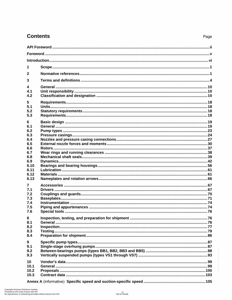
Contents Page
API Foreword ...................................................................................................................................................... ii
Foreword ............................................................................................................................................................. v
Introduction ........................................................................................................................................................ vi
1 Scope ...................................................................................................................................................... 1
2 Normative references ............................................................................................................................ 1
3 Terms and definitions ........................................................................................................................... 4
4 General ................................................................................................................................................. 10 4.1 Unit responsibility ............................................................................................................................... 10 4.2 Classification and designation .......................................................................................................... 10
5 Requirements ....................................................................................................................................... 18 5.1 Units ...................................................................................................................................................... 18 5.2 Statutory requirements ....................................................................................................................... 18 5.3 Requirements ....................................................................................................................................... 18
6 Basic design ........................................................................................................................................ 19 6.1 General ................................................................................................................................................. 19 6.2 Pump types .......................................................................................................................................... 23 6.3 Pressure casings ................................................................................................................................. 24 6.4 Nozzles and pressure casing connections ....................................................................................... 27 6.5 External nozzle forces and moments ................................................................................................ 30 6.6 Rotors ................................................................................................................................................... 37 6.7 Wear rings and running clearances .................................................................................................. 38 6.8 Mechanical shaft seals........................................................................................................................ 39 6.9 Dynamics .............................................................................................................................................. 42 6.10 Bearings and bearing housings ......................................................................................................... 56 6.11 Lubrication ........................................................................................................................................... 61 6.12 Materials ............................................................................................................................................... 61 6.13 Nameplates and rotation arrows ........................................................................................................ 66
7 Accessories ......................................................................................................................................... 67 7.1 Drivers .................................................................................................................................................. 67 7.2 Couplings and guards ......................................................................................................................... 70 7.3 Baseplates ............................................................................................................................................ 71 7.4 Instrumentation ................................................................................................................................... 74 7.5 Piping and appurtenances ................................................................................................................. 74 7.6 Special tools ........................................................................................................................................ 76
8 Inspection, testing, and preparation for shipment .......................................................................... 76 8.1 General ................................................................................................................................................. 76 8.2 Inspection ............................................................................................................................................. 77 8.3 Testing .................................................................................................................................................. 79 8.4 Preparation for shipment .................................................................................................................... 86
9 Specific pump types ............................................................................................................................ 87 9.1 Single-stage overhung pumps ........................................................................................................... 87 9.2 Between-bearings pumps (types BB1, BB2, BB3 and BB5) ........................................................... 88 9.3 Vertically suspended pumps (types VS1 through VS7) .................................................................. 93
10 Vendor's data ....................................................................................................................................... 99 10.1 General ................................................................................................................................................. 99 10.2 Proposals ........................................................................................................................................... 100 10.3 Contract data ..................................................................................................................................... 103
Annex A (informative) Specific speed and suction-specific speed ........................................................... 105
Copyright American Petroleum Institute Provided by IHS under license with API
Not for ResaleNo reproduction or networking permitted without license from IHS
--`,,```,,,,````-`-`,,`,,`,`,,`---
iv
Annex B (normative) Cooling water and lubrication system schematics ................................................ 106
Annex C (normative) Hydraulic power recovery turbines .......................................................................... 115
Annex D (normative) Standard baseplates .................................................................................................. 119
Annex E (informative) Inspector's checklist ................................................................................................ 121
Annex F (normative) Criteria for piping design .......................................................................................... 123
Annex G (informative) Materials class selection guidance ........................................................................ 137
Annex H (normative) Materials and material specifications for pump parts ........................................... 139
Annex I (normative) Lateral analysis ............................................................................................................ 147
Annex J (normative) Determination of residual unbalance ....................................................................... 154
Annex K (informative) Shaft stiffness and bearing system life ................................................................. 160
Annex L (informative) Vendor drawing and data requirements ................................................................ 166
Annex M (informative) Test data summary .................................................................................................. 175
Annex N (informative) Pump datasheets and electronic data exchange .................................................. 179
Annex O (informative) API Regional Annex ................................................................................................. 201
Bibliography ................................................................................................................................................... 202
Copyright American Petroleum Institute Provided by IHS under license with API
Not for ResaleNo reproduction or networking permitted without license from IHS
--`,,```,,,,````-`-`,,`,,`,`,,`---
v
Foreword
ISO (the International Organization for Standardization) is a worldwide federation of national standards bodies (ISO member bodies). The work of preparing International Standards is normally carried out through ISO technical committees. Each member body interested in a subject for which a technical committee has been established has the right to be represented on that committee. International organizations, governmental and non-governmental, in liaison with ISO, also take part in the work. ISO collaborates closely with the International Electrotechnical Commission (IEC) on all matters of electrotechnical standardization.
International Standards are drafted in accordance with the rules given in the ISO/IEC Directives, Part 2.
The main task of technical committees is to prepare International Standards. Draft International Standards adopted by the technical committees are circulated to the member bodies for voting. Publication as an International Standard requires approval by at least 75 % of the member bodies casting a vote.
Attention is drawn to the possibility that some of the elements of this document may be the subject of patent rights. ISO shall not be held responsible for identifying any or all such patent rights.
ISO 13709 was prepared by Technical Committee ISO/TC 115, Pumps, Subcommittee SC 3, Installation and special application, in collaboration with Technical Committee ISO/TC 67, Materials, equipment and offshore structures for petroleum, petrochemical and natural gas industries, SC 6, Processing equipment and systems.
This second edition cancels and replaces the first edition (ISO 13709:2003), which has been technically revised.
Copyright American Petroleum Institute Provided by IHS under license with API
Not for ResaleNo reproduction or networking permitted without license from IHS
--`,,```,,,,````-`-`,,`,,`,`,,`---
vi
Introduction
It is necessary that users of this International Standard be aware that further or differing requirements can be needed for individual applications. This International Standard is not intended to inhibit a vendor from offering, or the purchaser from accepting, alternative equipment or engineering solutions for the individual application. This can be particularly appropriate where there is innovative or developing technology. Where an alternative is offered, it is necessary that the vendor identify any variations from this International Standard and provide details.
A bullet ( ) at the beginning of a clause or subclause indicates that either a decision is required or the purchaser
is required to provide further information. It is necessary that this information should be indicated on data sheets or stated in the enquiry or purchase order (see examples in Annex N).
In this International Standard, where practical, US Customary, or other, units are included in parentheses for information.
Copyright American Petroleum Institute Provided by IHS under license with API
Not for ResaleNo reproduction or networking permitted without license from IHS
--`,,```,,,,````-`-`,,`,,`,`,,`---
API Standard 610/ISO 13709
1
Centrifugal pumps for petroleum, petrochemical and natural gas industries
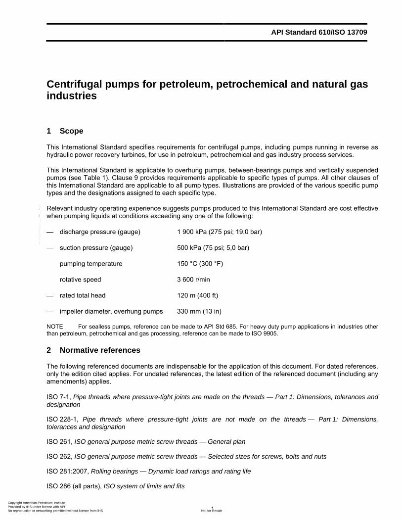
1 Scope
This International Standard specifies requirements for centrifugal pumps, including pumps running in reverse as hydraulic power recovery turbines, for use in petroleum, petrochemical and gas industry process services.
This International Standard is applicable to overhung pumps, between-bearings pumps and vertically suspended pumps (see Table 1). Clause 9 provides requirements applicable to specific types of pumps. All other clauses of this International Standard are applicable to all pump types. Illustrations are provided of the various specific pump types and the designations assigned to each specific type.
Relevant industry operating experience suggests pumps produced to this International Standard are cost effective when pumping liquids at conditions exceeding any one of the following:
discharge pressure (gauge) 1 900 kPa (275 psi; 19,0 bar)
suction pressure (gauge) 500 kPa (75 psi; 5,0 bar)
pumping temperature 150 °C (300 °F)
rotative speed 3 600 r/min
rated total head 120 m (400 ft)
impeller diameter, overhung pumps 330 mm (13 in)
NOTE For sealless pumps, reference can be made to API Std 685. For heavy duty pump applications in industries other than petroleum, petrochemical and gas processing, reference can be made to ISO 9905.
2 Normative references
The following referenced documents are indispensable for the application of this document. For dated references, only the edition cited applies. For undated references, the latest edition of the referenced document (including any amendments) applies.
ISO 7-1, Pipe threads where pressure-tight joints are made on the threads — Part 1: Dimensions, tolerances and designation
ISO 228-1, Pipe threads where pressure-tight joints are not made on the threads — Part 1: Dimensions, tolerances and designation
ISO 261, ISO general purpose metric screw threads — General plan
ISO 262, ISO general purpose metric screw threads — Selected sizes for screws, bolts and nuts
ISO 281:2007, Rolling bearings — Dynamic load ratings and rating life
ISO 286 (all parts), ISO system of limits and fits
Copyright American Petroleum Institute Provided by IHS under license with API
Not for ResaleNo reproduction or networking permitted without license from IHS
--`,,```,,,,````-`-`,,`,,`,`,,`---
2 CENTRIFUGAL PUMPS FOR PETROLEUM, PETROCHEMICAL AND NATURAL GAS INDUSTRIES
ISO 724, ISO general-purpose metric screw threads — Basic dimensions
ISO 965 (all parts), ISO general-purpose metric screw threads — Tolerances
ISO 1940-1, Mechanical vibration — Balance quality requirements for rotors in a constant (rigid) state — Part 1: Specification and verification of balance tolerances
ISO 3117, Tangential keys and keyways
ISO 4200, Plain end steel tubes, welded and seamless — General tables of dimensions and masses per unit length
ISO 5753, Rolling bearings — Radial internal clearance
ISO 7005-1, Metallic flanges — Part 1: Steel flanges for industrial and general service piping systems
ISO 7005-2, Metallic flanges — Part 2: Cast iron flanges
ISO 8501 (all parts), Preparation of steel substrates before application of paints and related products — Visual assessment of surface cleanliness
ISO 9606 (all parts), Approval testing of welders — Fusion welding1)
ISO 9906, Rotodynamic pumps — Hydraulic performance acceptance tests2)
ISO 10438:2007 (all parts), Petroleum, petrochemical and natural gas industries — Lubrication, shaft-sealing and control-oil systems and auxiliaries
ISO 10441, Petroleum, petrochemical and natural gas industries — Flexible couplings for mechanical power transmission — Special-purpose applications
ISO 10721-2, Steel structures — Part 2: Fabrication and erection
ISO 11342, Mechanical vibration — Methods and criteria for the mechanical balancing of flexible rotors
ISO 14120, Safety of machinery — Guards — General requirements for the design and construction of fixed and movable guards
ISO 14691, Petroleum, petrochemical and natural gas industries — Flexible couplings for mechanical power transmission — General-purpose applications
ISO 15156-1, Petroleum and natural gas industries — Materials for use in H2S-containing environments in oil and gas production — Part 1: General principles for selection of cracking-resistant materials
ISO 15609 (all parts), Specification and qualification of welding procedures for metallic materials — Welding procedure specification
ISO 15649, Petroleum and natural gas industries — Piping
ISO/TR 17766, Centrifugal pumps handling viscous liquids — Performance corrections
ISO 21049:2004, Pumps — Shaft sealing systems for centrifugal and rotary pumps
IEC 60034-1, Rotating electrical machines — Part 1: Rating and performance
1) Some parts of ISO 9606 are under revision and some revised parts have been published with Qualification test of welders as the main title.
2) To be published. (Revision of ISO 9906:1999) Copyright American Petroleum Institute Provided by IHS under license with API
Not for ResaleNo reproduction or networking permitted without license from IHS
--`,,```,,,,````-`-`,,`,,`,`,,`---
API STANDARD 610/ISO 13709 3
IEC 60034-2-1, Rotating electrical machines — Part 2-1: Standard methods for determining losses and efficiency from tests (excluding machines for traction vehicles)
IEC 60079 (all parts), Electrical apparatus for explosive gas atmospheres3)
EN 953, Safety of machinery — Guards — General requirements for the design and construction of fixed and movable guards
EN 13445 (all parts), Unfired pressure vessels
EN 13463-1, Non-electrical equipment for use in potentially explosive atmospheres — Part 1: Basic method and requirements
ANSI/ABMA 7, Shaft and Housing Fits for Metric Radial Ball and Roller Bearings (Except Tapered Roller
Bearings) Conforming to Basic Boundary Plan 4)
ANSI/AGMA 9000, Flexible Couplings — Potential Unbalance Classification5)
ANSI/AGMA 9002, Bores and Keyways for Flexible Couplings (Inch Series)
ANSI/AMT B15.1, Safety Standard for Mechanical Power Transmission Apparatus6)
ANSI/API Std 541, Form-Wound Squirrel-Cage Induction Motors — 500 Horsepower and Larger
ANSI/API Std 611, General-Purpose Steam Turbines for Petroleum, Chemical, and Gas Industry Services
ANSI/API Std 670, Machinery Protection Systems
ANSI/API Std 671/ISO 10441, Special Purpose Couplings for Petroleum, Chemical and Gas Industry Services
ANSI/ASME B1.1, Unified Inch Screw Threads, UN and UNR Thread Form7)
ANSI/ASME B16.1, Gray Iron Pipe Flanges and Flanged Fittings: Classes 25, 125 and 250
ANSI/ASME B16.5, Pipe Flanges and Flanged Fittings: NPS 1/2 through NPS 24 Metric/Inch Standard
ANSI/ASME B16.11, Forged Steel Fittings, Socket-Welding and Threaded
ANSI/ASME B16.42, Ductile Iron Pipe Flanges and Flanged Fittings, Classes 150 and 300
ANSI/ASME B16.47, Larger Diameter Steel Flanges: NPS 26 Through NPS 60
ANSI/ASME B18.18.2M, Inspection and Quality Assurance for High-Volume Machine Assembly Fasteners
ANSI/ASME B31.3, Process Piping
ANSI/HI 1.6, Centrifugal Tests8)
ANSI/HI 2.6, American National Standard for Vertical Pump Tests
3) Many parts of this standard have Explosive atmospheres as the main title.
4) American Bearing Manufacturers Association, 2025 M Street, NW, Suite 800, Washington, DC 20036, USA.
5) American Gear Manufacturers Association, 1500 King Street, Suite 201, Alexandria, VA 22314, USA.
6) American National Standards Institute, 1819 L Street, Suite 600, Washington, D.C. 20036, USA.
7) American Society of Mechanical Engineers, Three Park Avenue, New York, NY 10016-5990, USA.
8) Hydraulic Institute, 9 Sylvan Way, Parsippany, NJ 07054, USA. Copyright American Petroleum Institute Provided by IHS under license with API
Not for ResaleNo reproduction or networking permitted without license from IHS
--`,,```,,,,````-`-`,,`,,`,`,,`---
4 CENTRIFUGAL PUMPS FOR PETROLEUM, PETROCHEMICAL AND NATURAL GAS INDUSTRIES
API Std 547, General-Purpose Form-Wound Squirrel Cage Induction Motors — 250 Horsepower and Larger
API Std 677, General-Purpose Gear Units for Petroleum, Chemical and Gas Industry Services
ASME, Boiler and pressure vessel code BPVC, Section V, Nondestructive Examination
ASME, Boiler and pressure vessel code BPVC, Section VIII, Rules for Construction of Pressure Vessels
ASME, Boiler and pressure vessel code BPVC, Section IX, Welding and Brazing Qualifications
DIN 910, Heavy-duty hexagon head screw plugs9)
IEEE 841, IEEE Standard for Petroleum and Chemical Industry — Severe Duty Totally Enclosed Fan-Cooled
(TEFC) Squirrel Cage Induction Motors — Up to and Including 500 hp10)
MSS SP-55, Quality Standard for Steel Castings for Valves, Flanges and Fittings and Other Piping Components — Visual Method for Evaluation of Surface Irregularities11)
NACE MR0103, Materials Resistant to Sulfide Stress Cracking in Corrosive Petroleum Refining Environments12)
NFPA 70:2008, National Electrical Code13)
SSPC SP 6, Commercial Blast Cleaning14)
3 Terms and definitions
For the purposes of this document, the following terms and definitions apply.
3.1 axially split split with the principal joint parallel to the shaft centreline
3.2 allowable operating region portion of a pump's hydraulic coverage over which the pump is allowed to operate, based on vibration within the upper limit of this International Standard or temperature rise or other limitation, specified by the manufacturer
3.3 barrel pump horizontal pump of the double-casing type
3.4 barrier fluid externally supplied fluid, at a pressure above the pump seal chamber pressure, introduced into an Arrangement 3 seal (pressurized dual mechanical seal) to completely isolate the pump process liquid from the environment
9) Deutsches Institut für Normung, Burggrafenstrasse 6, Berlin, Germany D-10787.
10) Institute of Electrical & Electronics Engineers, 445 Hoes Lane, Piscataway, NJ 08855-1331, USA.
11) Manufacturers Standardization Society of The Valve and Fittings Industry Inc., 127 Park Street N.E., Vienna, VA 22180-4602, USA.
12) National Association of Corrosion Engineers, Houston, Texas, USA.
13) National Fire Protection Association, 1 Batterymarch Park, Quincy, MA 02169-7471, USA.
14) Society for Protective Coatings, 40 24th Street, 6th Floor, Pittsburgh, PA 15222-4643, USA. Copyright American Petroleum Institute Provided by IHS under license with API
Not for ResaleNo reproduction or networking permitted without license from IHS
--`,,```,,,,````-`-`,,`,,`,`,,`---
API STANDARD 610/ISO 13709 5
3.5 best efficiency point BEP flowrate at which a pump achieves its highest efficiency at rated impeller diameter
NOTE The best efficiency point flowrate at maximum impeller diameter is used to determine pump specific speed and suction specific speed. The best efficiency point flowrate at reduced impeller diameters is similarly reduced from the value at maximum impeller diameter.
3.6 buffer fluid externally supplied fluid, at a pressure lower than the pump seal chamber pressure, used as a lubricant and/or to provide a diluent in an Arrangement 2 seal (unpressurized dual mechanical seal)
3.7 cartridge-type element assembly of all the parts of the pump except for the casing
3.8 classically stiff characterized by the first dry critical speed being above the pump's maximum continuous speed by the following:
20 % for rotors designed for wet running only
30 % for rotors designed to be able to run dry
3.9 critical speed shaft rotational speed at which the rotor-bearing-support system is in a state of resonance
3.10 datum elevation elevation to which values of NPSH are referred (see 6.1.8)
cf. net positive suction head (3.33)
3.11 design manufacturer's calculated parameter
NOTE ―Design‖ is a term that may be used by the equipment manufacturer to describe various parameters, such as design power, design pressure, design temperature, or design speed. This term should be used only by the equipment manufacturer and not in the purchaser's specifications.
3.12 double casing type of pump construction in which the pressure casing is separate from the pumping elements contained in the casing
NOTE Examples of pumping elements include diffuser, diaphragms, bowls and volute inner casings.
3.13 drive-train component item of the equipment used in series to drive the pump
EXAMPLES Motor, gear, turbine, engine, fluid drive, clutch.
3.14 dry critical speed rotor critical speed calculated assuming that there are no liquid effects, that the rotor is supported only at its bearings and that the bearings are of infinite stiffness
Copyright American Petroleum Institute Provided by IHS under license with API
Not for ResaleNo reproduction or networking permitted without license from IHS
--`,,```,,,,````-`-`,,`,,`,`,,`---
6 CENTRIFUGAL PUMPS FOR PETROLEUM, PETROCHEMICAL AND NATURAL GAS INDUSTRIES
3.15 element bundle assembly of the rotor plus the internal stationary parts of a centrifugal pump
3.16 hydraulic power recovery turbine HPRT turbomachine designed to recover power from a fluid stream
3.17 hydrodynamic bearing bearing that uses the principles of hydrodynamic lubrication
3.18 identical pump pump of the same size, hydraulic design, number of stages, rotational speed, clearances, type of shaft seal (axial face or breakdown bushing), type of bearings, coupling mass, coupling overhang, and pumping the same liquid
3.19 maximum allowable speed highest speed at which the manufacturer's design permits continuous operation
3.20 maximum allowable temperature maximum continuous temperature for which the manufacturer has designed the pump (or any part to which the term is referred) when pumping the specified liquid at the specified maximum operating pressure (does not include mechanical seal)
cf. pressure casing (3.43)
3.21 maximum allowable working pressure MAWP maximum continuous pressure for which the manufacturer has designed the pump (or any part to which the term is referred) when pumping the specified liquid at the specified maximum operating temperature (does not include mechanical seal)
3.22 maximum discharge pressure maximum specified suction pressure plus the maximum differential pressure the pump with the furnished impeller is able to develop when operating at rated speed with liquid of the specified normal relative density (specific gravity)
3.23 maximum dynamic sealing pressure highest pressure expected at the seals during any specified operating condition and during start-up and shut-down
NOTE Both dynamic and static sealing pressures are important to selection of the mechanical seal. They are dependent on the pump suction pressure, operating point and pump clearances. They are also affected by the pressure of the seal flush. This pressure is specified to the seal vendor. See ISO 21049 or ANSI/API Std 682/ISO 21049.
3.24 maximum operating temperature highest temperature of the pumped liquid, including upset conditions, to which the pump is exposed
NOTE This temperature is specified to the seal vendor. See ISO 21049 or ANSI/API Std 682/ISO 21049.
Copyright American Petroleum Institute Provided by IHS under license with API
Not for ResaleNo reproduction or networking permitted without license from IHS
--`,,```,,,,````-`-`,,`,,`,`,,`---

API STANDARD 610/ISO 13709 7
3.25 maximum static sealing pressure highest pressure, excluding pressures encountered during hydrostatic testing, to which the seals can be subjected while the pump is shut down
3.26 maximum suction pressure highest suction pressure to which the pump is subjected during operation (non-transient; does not include waterhammer)
3.27 minimum allowable speed lowest speed at which the manufacturer's design permits continuous operation
NOTE The speed is expressed in units of revolutions per minute.
3.28 minimum continuous stable flow lowest flow at which the pump can operate without exceeding the vibration limits imposed by this International Standard
3.29 minimum continuous thermal flow lowest flow at which the pump can operate without its operation being impaired by the temperature rise of the pumped liquid
3.30 minimum design metal temperature lowest mean metal temperature (through the thickness) expected in service, including operation upsets, auto-refrigeration and temperature of the surrounding environment, for which the equipment is designed
3.31 multistage pump pump with three or more stages
See 4.2.
3.32 nominal pipe size NPS designation, usually followed by a size designation number, corresponding approximately to the outside diameter of the pipe
NOTE The NPS is expressed in inches.
3.33 NPSH net positive suction head absolute inlet total head above the head equivalent to the vapour pressure referred to the NPSH datum plane
NOTE NPSH is expressed in metres (feet) of head of the pumped liquid.
3.34 net positive suction head available NPSHA NPSH determined by the purchaser for the pumping system with the liquid at the rated flow and normal pumping temperature
Copyright American Petroleum Institute Provided by IHS under license with API
Not for ResaleNo reproduction or networking permitted without license from IHS
--`,,```,,,,````-`-`,,`,,`,`,,`---

8 CENTRIFUGAL PUMPS FOR PETROLEUM, PETROCHEMICAL AND NATURAL GAS INDUSTRIES
3.35 net positive suction head required NPSH3 NPSH that results in a 3 % loss of head (first-stage head in a multistage pump) determined by the vendor by testing with water
3.36 normal operating point point at which the pump is expected to operate under normal process conditions
3.37 normal-wear part part normally restored or replaced at each pump overhaul
EXAMPLES Wear rings, inter-stage bushings, balancing device, throat bushing, seal faces, bearings and gaskets.
3.38 observed inspection observed test inspection or test where the purchaser is notified of the timing of the inspection or test and the inspection or test is performed as scheduled, regardless of whether the purchaser or his representative is present
3.39 oil-mist lubrication lubrication provided by oil mist produced by atomization and transported to the bearing housing, or housings, by compressed air
3.40 operating region portion of a pump's hydraulic coverage over which the pump operates
3.41 overhung pump pump whose impeller is supported by a cantilever shaft from its bearing assembly
3.42 preferred operating region portion of a pump's hydraulic coverage over which the pump's vibration is within the base limit of this International Standard
3.43 pressure casing composite of all stationary pressure-containing parts of the pump, including all nozzles, seal glands, seal chambers and auxiliary connections but excluding the stationary and rotating members of mechanical seals
NOTE The atmospheric side of the seal gland, the seal flush (piping) plan, auxiliary piping and valves are not part of the pressure casing.
3.44 purchaser owner, or owner's agent, who issues the order and specification to the vendor
3.45 pure oil-mist lubrication
dry sump system in which the mist both lubricates the bearing(s) and purges the housing and there is no oil level in the sump
3.46 purge oil-mist lubrication
wet sump systems in which the mist only purges the bearing housing Copyright American Petroleum Institute Provided by IHS under license with API
Not for ResaleNo reproduction or networking permitted without license from IHS
--`,,```,,,,````-`-`,,`,,`,`,,`---

API STANDARD 610/ISO 13709 9
3.47 radially split split with the principal joint perpendicular to the shaft centreline
3.48 rated operating point point at which the vendor certifies that pump performance is within the tolerances stated in this International Standard
NOTE Normally, the rated operating point is the specified operating point with the highest flow.
3.49 relative density specific gravity property of a liquid expressed as the ratio of the liquid's density to that of water at standard temperature
NOTE Standard temperature is 4 °C (39,2 °F).
3.50 rotor assembly of all the rotating parts of a centrifugal pump
3.51 similar pump pump that is accepted, by agreement between purchaser and manufacturer as sufficiently similar to not require a lateral analysis, taking into account the factors listed for an identical pump (3.18)
3.52 specific speed index relating flow, total head and rotational speed for pumps of similar geometry
3.53 stage one impeller and associated diffuser or volute and return channel, if required
3.54 suction-specific speed index relating flow, NPSH3 and rotative speed for pumps of similar geometry
3.55 throat bushing device that forms a restrictive close clearance around the sleeve (or shaft) between the seal or inner seal of a dual seal cartridge and the impeller
3.56 total indicator reading total indicated runout TIR difference between the maximum and minimum readings of a dial indicator or similar device, monitoring a face or cylindrical surface, during one complete revolution of the monitored surface
NOTE For a perfectly cylindrical surface, the indicator reading implies an eccentricity equal to half the reading. For a perfectly flat face the indicator reading gives an out-of-squareness equal to the reading. If the diameter in question is not perfectly cylindrical or flat, interpretation of the meaning of TIR is more complex and can represent ovality or lobing.
3.57 trip speed
electric motor driver -synchronous speed at maximum supply frequency
Copyright American Petroleum Institute Provided by IHS under license with API
Not for ResaleNo reproduction or networking permitted without license from IHS
--`,,```,,,,````-`-`,,`,,`,`,,`---

10 CENTRIFUGAL PUMPS FOR PETROLEUM, PETROCHEMICAL AND NATURAL GAS INDUSTRIES
3.58 trip speed
variable-speed driver variable- -speed at which the independent emergency over-speed device operates to shut down the driver
3.59 unit responsibility responsibility for coordinating the documentation, delivery and technical aspects of the equipment and all auxiliary systems included in the scope of the order
NOTE The technical aspects for consideration include, but are not limited to, such factors as the power requirements, speed, rotation, general arrangement, couplings, dynamics, lubrication, sealing system, material test reports, instrumentation, piping, conformance to specifications and testing of components.
3.60 vendor supplier manufacturer or manufacturer's agent that supplies the equipment and is normally responsible for service support
3.61 vertical in-line pump vertical-axis, single-stage overhung pump whose suction and discharge connections have a common centreline that intersects the shaft axis
NOTE Types VS6 and VS7 are not considered in-line pumps.
3.62 vertically suspended pump vertical-axis pump whose liquid end is suspended from a column and mounting plate
NOTE The pump's liquid end is usually submerged in the pumped liquid.
3.63 wet critical speed rotor critical speed calculated considering the additional support and damping produced by the action of the pumped liquid within internal running clearances at the operating conditions and allowing for stiffness and damping within the bearings
3.64 witnessed test witnessed inspection inspection or test for which the purchaser is notified of the timing of the inspection or test and a hold is placed on the inspection or test until the purchaser or his representative is in attendance
4 General
4.1 Unit responsibility
Unless otherwise specified, the pump vendor shall have unit responsibility. The pump vendor shall ensure that all sub-vendors comply with the requirements of this International Standard and all reference documents.
4.2 Classification and designation
4.2.1 Description of codes
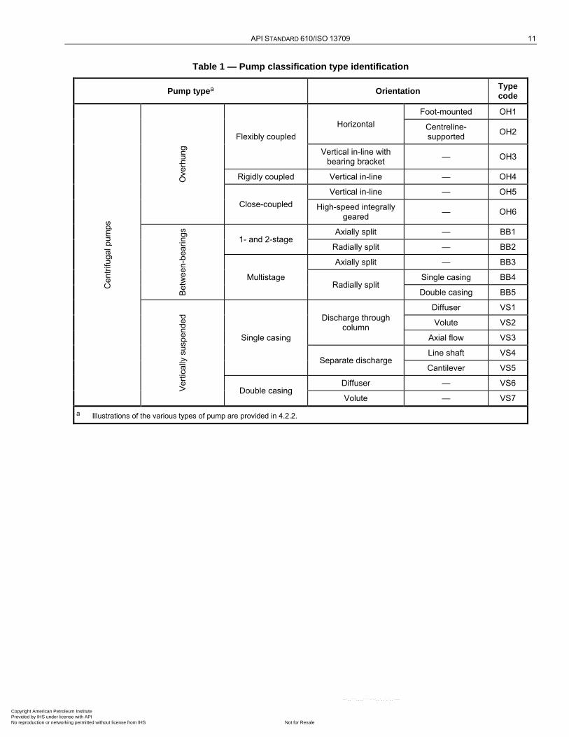
The pumps described in this International Standard are classified and designated by type codes, as shown in Table 1.
Copyright American Petroleum Institute Provided by IHS under license with API
Not for ResaleNo reproduction or networking permitted without license from IHS
--`,,```,,,,````-`-`,,`,,`,`,,`---
API STANDARD 610/ISO 13709 11
Table 1 — Pump classification type identification
Pump typea Orientation Type code
Centr
ifu
gal p
um
ps
Ove
rhu
ng
Flexibly coupled
Horizontal
Foot-mounted OH1
Centreline- supported
OH2
Vertical in-line with bearing bracket
— OH3
Rigidly coupled Vertical in-line — OH4
Close-coupled
Vertical in-line — OH5
High-speed integrally geared
— OH6
Betw
een-b
eari
ngs
1- and 2-stage Axially split — BB1
Radially split — BB2
Multistage
Axially split — BB3
Radially split Single casing BB4
Double casing BB5
Vert
ically
suspend
ed
Single casing
Discharge through column
Diffuser VS1
Volute VS2
Axial flow VS3
Separate discharge Line shaft VS4
Cantilever VS5
Double casing Diffuser — VS6
Volute — VS7
a Illustrations of the various types of pump are provided in 4.2.2.
Copyright American Petroleum Institute Provided by IHS under license with API
Not for ResaleNo reproduction or networking permitted without license from IHS
--`,,```,,,,````-`-`,,`,,`,`,,`---
12 CENTRIFUGAL PUMPS FOR PETROLEUM, PETROCHEMICAL AND NATURAL GAS INDUSTRIES
4.2.2 Pump designations and descriptions
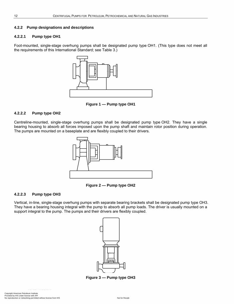
4.2.2.1 Pump type OH1
Foot-mounted, single-stage overhung pumps shall be designated pump type OH1. (This type does not meet all the requirements of this International Standard; see Table 3.)
Figure 1 — Pump type OH1
4.2.2.2 Pump type OH2
Centreline-mounted, single-stage overhung pumps shall be designated pump type OH2. They have a single bearing housing to absorb all forces imposed upon the pump shaft and maintain rotor position during operation. The pumps are mounted on a baseplate and are flexibly coupled to their drivers.
Figure 2 — Pump type OH2
4.2.2.3 Pump type OH3
Vertical, in-line, single-stage overhung pumps with separate bearing brackets shall be designated pump type OH3. They have a bearing housing integral with the pump to absorb all pump loads. The driver is usually mounted on a support integral to the pump. The pumps and their drivers are flexibly coupled.
Figure 3 — Pump type OH3
Copyright American Petroleum Institute Provided by IHS under license with API
Not for ResaleNo reproduction or networking permitted without license from IHS
--`,,```,,,,````-`-`,,`,,`,`,,`---
API STANDARD 610/ISO 13709 13
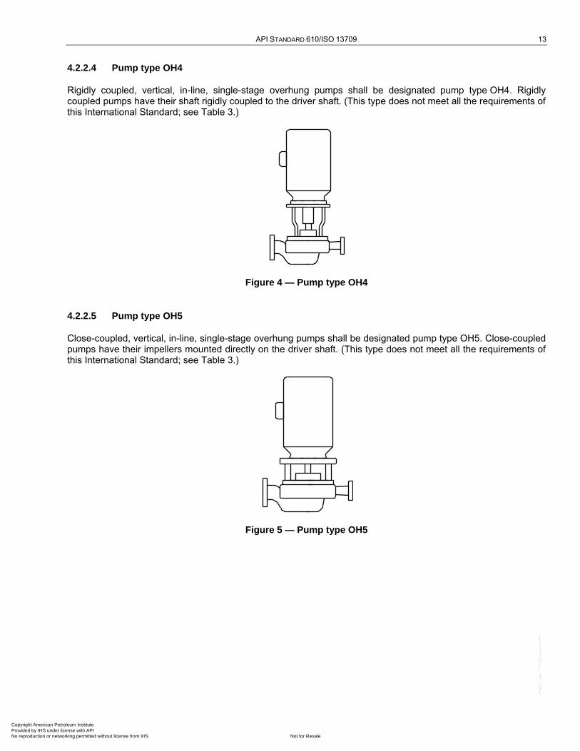
4.2.2.4 Pump type OH4
Rigidly coupled, vertical, in-line, single-stage overhung pumps shall be designated pump type OH4. Rigidly coupled pumps have their shaft rigidly coupled to the driver shaft. (This type does not meet all the requirements of this International Standard; see Table 3.)
Figure 4 — Pump type OH4
4.2.2.5 Pump type OH5
Close-coupled, vertical, in-line, single-stage overhung pumps shall be designated pump type OH5. Close-coupled pumps have their impellers mounted directly on the driver shaft. (This type does not meet all the requirements of this International Standard; see Table 3.)
Figure 5 — Pump type OH5
Copyright American Petroleum Institute Provided by IHS under license with API
Not for ResaleNo reproduction or networking permitted without license from IHS
--`,,```,,,,````-`-`,,`,,`,`,,`---

14 CENTRIFUGAL PUMPS FOR PETROLEUM, PETROCHEMICAL AND NATURAL GAS INDUSTRIES
4.2.2.6 Pump type OH6
High-speed, integral, gear-driven, single-stage overhung pumps shall be designated pump type OH6. These pumps have a speed-increasing gearbox integral with the pump. The impeller is mounted directly to the gearbox output shaft. There is no coupling between the gearbox and pump; however, the gearbox is flexibly coupled to its driver. The pumps may be oriented vertically or horizontally.
Figure 6 — Pump type OH6
4.2.2.7 Pump type BB1
Axially split, one- and two-stage, between-bearings pumps shall be designated pump type BB1.
Figure 7 — Pump type BB1
Copyright American Petroleum Institute Provided by IHS under license with API
Not for ResaleNo reproduction or networking permitted without license from IHS
--`,,```,,,,````-`-`,,`,,`,`,,`---
API STANDARD 610/ISO 13709 15
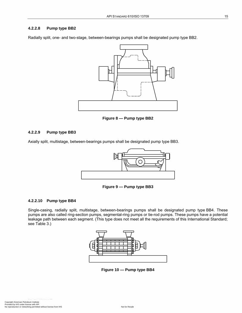
4.2.2.8 Pump type BB2
Radially split, one- and two-stage, between-bearings pumps shall be designated pump type BB2.
Figure 8 — Pump type BB2
4.2.2.9 Pump type BB3
Axially split, multistage, between-bearings pumps shall be designated pump type BB3.
Figure 9 — Pump type BB3
4.2.2.10 Pump type BB4
Single-casing, radially split, multistage, between-bearings pumps shall be designated pump type BB4. These pumps are also called ring-section pumps, segmental-ring pumps or tie-rod pumps. These pumps have a potential leakage path between each segment. (This type does not meet all the requirements of this International Standard; see Table 3.)
Figure 10 — Pump type BB4
Copyright American Petroleum Institute Provided by IHS under license with API
Not for ResaleNo reproduction or networking permitted without license from IHS
--`,,```,,,,````-`-`,,`,,`,`,,`---
16 CENTRIFUGAL PUMPS FOR PETROLEUM, PETROCHEMICAL AND NATURAL GAS INDUSTRIES
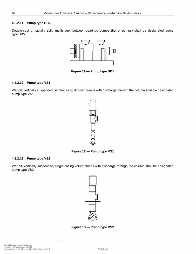
4.2.2.11 Pump type BB5
Double-casing, radially split, multistage, between-bearings pumps (barrel pumps) shall be designated pump type BB5.
Figure 11 — Pump type BB5
4.2.2.12 Pump type VS1
Wet pit, vertically suspended, single-casing diffuser pumps with discharge through the column shall be designated pump type VS1.
Figure 12 — Pump type VS1
4.2.2.13 Pump type VS2
Wet pit, vertically suspended, single-casing volute pumps with discharge through the column shall be designated pump type VS2.
Figure 13 — Pump type VS2
Copyright American Petroleum Institute Provided by IHS under license with API
Not for ResaleNo reproduction or networking permitted without license from IHS
--`,,```,,,,````-`-`,,`,,`,`,,`---
API STANDARD 610/ISO 13709 17
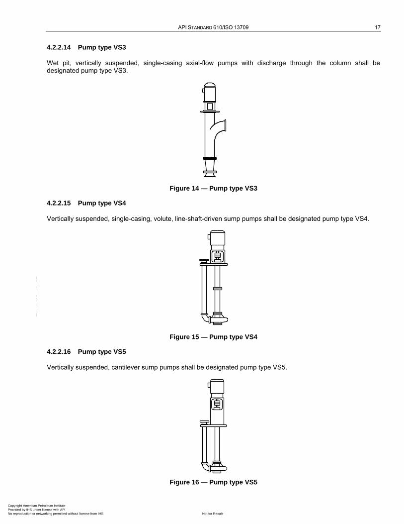
4.2.2.14 Pump type VS3
Wet pit, vertically suspended, single-casing axial-flow pumps with discharge through the column shall be designated pump type VS3.
Figure 14 — Pump type VS3
4.2.2.15 Pump type VS4
Vertically suspended, single-casing, volute, line-shaft-driven sump pumps shall be designated pump type VS4.
Figure 15 — Pump type VS4
4.2.2.16 Pump type VS5
Vertically suspended, cantilever sump pumps shall be designated pump type VS5.
Figure 16 — Pump type VS5
Copyright American Petroleum Institute Provided by IHS under license with API
Not for ResaleNo reproduction or networking permitted without license from IHS
--`,,```,,,,````-`-`,,`,,`,`,,`---
18 CENTRIFUGAL PUMPS FOR PETROLEUM, PETROCHEMICAL AND NATURAL GAS INDUSTRIES
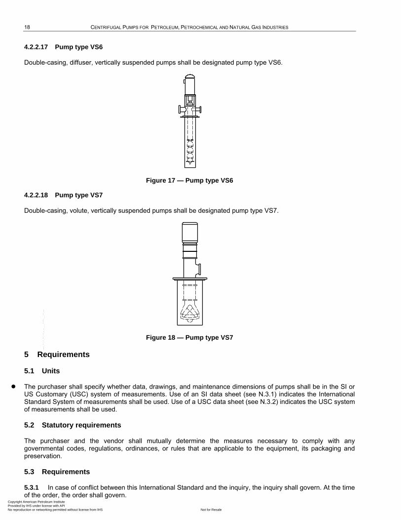
4.2.2.17 Pump type VS6
Double-casing, diffuser, vertically suspended pumps shall be designated pump type VS6.
Figure 17 — Pump type VS6
4.2.2.18 Pump type VS7
Double-casing, volute, vertically suspended pumps shall be designated pump type VS7.
Figure 18 — Pump type VS7
5 Requirements
5.1 Units
The purchaser shall specify whether data, drawings, and maintenance dimensions of pumps shall be in the SI or US Customary (USC) system of measurements. Use of an SI data sheet (see N.3.1) indicates the International Standard System of measurements shall be used. Use of a USC data sheet (see N.3.2) indicates the USC system of measurements shall be used.
5.2 Statutory requirements
The purchaser and the vendor shall mutually determine the measures necessary to comply with any governmental codes, regulations, ordinances, or rules that are applicable to the equipment, its packaging and preservation.
5.3 Requirements
5.3.1 In case of conflict between this International Standard and the inquiry, the inquiry shall govern. At the time of the order, the order shall govern.
Copyright American Petroleum Institute Provided by IHS under license with API
Not for ResaleNo reproduction or networking permitted without license from IHS
--`,,```,,,,````-`-`,,`,,`,`,,`---
API STANDARD 610/ISO 13709 19
5.3.2 Where requirements specific to a particular pump type in Clause 9 conflict with any other clauses, the requirements of Clause 9 shall govern.
6 Basic design
6.1 General
6.1.1 The equipment (including auxiliaries) covered by this International Standard shall be designed and constructed for a minimum service life of 20 years (excluding normal-wear parts as identified in Table 20) and at least 3 years of uninterrupted operation. Shutting down the equipment to perform vendor-specified maintenance or inspection does not meet the continuous uninterrupted operation requirement. It is recognized that these requirements are design criteria and that service or duty severity, mis-operation or improper maintenance can result in a machine failing to meet these criteria.
6.1.2 The purchaser shall specify the operating conditions, the liquid properties, site conditions and utility conditions, including all data shown on the process data sheet (Annex N). The purchaser shall specify whether the pump is intended for use as an HPRT and whether Annex C shall apply.
6.1.3 The equipment shall be capable of operation at the normal and rated operating points and any other anticipated operating conditions specified by the purchaser.
6.1.4 Pumps shall be capable of at least a 5 % head increase at rated conditions by replacement of the impeller(s) with one(s) of larger diameter or different hydraulic design, variable-speed capability or use of a blank stage.
This requirement is intended to prevent a change in selection caused by refinement of hydraulic requirements after the pump has been purchased. It is not intended to accommodate future expandability. If there is a future operating requirement, it should be specified separately and considered in selection.
6.1.5 Pumps shall be capable of operating at least up to the maximum continuous speed. The maximum continuous speed shall be
a) equal to the speed corresponding to the synchronous speed at maximum supply frequency for electrical motors;
b) at least 105 % of rated speed for variable-speed pumps, and any fixed-speed pump sparing or spared by a pump whose driver is capable of exceeding rated speed.
6.1.6 Variable-speed pumps shall be designed for excursions to trip speed without damage.
6.1.7 The conditions in the seal chamber required to maintain a stable film at the seal faces, including temperature, pressure and flow, as well as provisions for assuring the adequacy of the design for sealing against atmospheric pressure when pumps are idle in vacuum service, shall be agreed upon by the pump vendor and the seal manufacturer, approved by the purchaser, and noted on the data sheet.
Provision for sealing against atmospheric pressure in vacuum service is especially important when handling liquids near their vapour pressure (such as liquefied petroleum gases). During operation, the seal chamber pressure shall be at least a gauge pressure of 35 kPa (0,35 bar; 5 psi); see ISO 21049.
6.1.8 The vendor shall specify on the data sheets the NPSH3 based on water [at a temperature of less than 55 °C (130 °F)] at the rated flow and rated speed. A reduction or correction factor for liquids other than water (such as hydrocarbons) shall not be applied.
The purchaser should consider an appropriate NPSH margin in addition to the NPSH3 specified. An NPSH margin is the NPSH that exists in excess of the pump's NPSH3. It is usually desirable to have an operating NPSH margin that is sufficient at all flows (from minimum continuous stable flow to maximum expected operating flow) to protect the pump from damage caused by flow recirculation, separation and cavitation. The vendor should be consulted about recommended NPSH margins for the specific pump type and intended service.
Copyright American Petroleum Institute Provided by IHS under license with API
Not for ResaleNo reproduction or networking permitted without license from IHS
--`,,```,,,,````-`-`,,`,,`,`,,`---

20 CENTRIFUGAL PUMPS FOR PETROLEUM, PETROCHEMICAL AND NATURAL GAS INDUSTRIES
In establishing the NPSHA, the purchaser and the vendor should recognize the relationship between minimum continuous stable flow and the pump's suction-specific speed. In general, minimum continuous stable flow increases as suction-specific speed increases. However, other factors, such as the pump's energy level and hydraulic design, the pumped liquid and the NPSH margin, also affect the pump's ability to operate satisfactorily over a wide flow range. Pump design that addresses low-flow operation is an evolving technology, and selection of suction-specific speed levels and NPSH margins should take into account current industry and vendor experience.
Unless otherwise specified, the datum elevation shall be the shaft centreline for horizontal pumps, the suction-nozzle centreline for vertical in-line pumps, and the top of the foundation for vertically suspended pumps.
6.1.9 The pump suction-specific speed shall be calculated in accordance with Annex A and, if specified, limited as stated on the data sheet.
6.1.10 Pumps that handle liquids more viscous than water shall have their water performance corrected in accordance with ISO/TR 17766. Correction factors used for viscous liquid shall be submitted with both sales proposal curves and final test curves.
NOTE For the purpose of this provision, ANSI/HI 9.6.7 is equivalent to ISO/TR 17766.
6.1.11 Pumps that have stable head/flowrate curves (continuous head rise to shutoff) are preferred for all applications and are required if parallel operation is specified. If parallel operation is specified, the head rise from rated point to shutoff shall be at least 10 %. If a discharge orifice is used as a means of providing a continuous rise to shutoff, this use shall be stated in the proposal.
6.1.12 Pumps shall have a preferred operating region of 70 % to 120 % of best efficiency flowrate of the pump as furnished. Rated flow shall be within the region of 80 % to 110 % of best efficiency flowrate of the pump as furnished.
Setting limits for the preferred operating region and the location of rated flow is not intended to lead to the development of additional sizes of small pumps or preclude the use of high-specific-speed pumps. Small pumps that are known to operate satisfactorily at flows outside the specified limits and high-specific-speed pumps that may have a narrower preferred operating region than specified should be offered, where appropriate, and their preferred operating region clearly shown on the proposal curve. The pump specific speed shall be calculated in accordance with Annex A.
NOTE ―Best efficiency flowrate of the pump as furnished‖ refers to the pump with the impeller diameter properly selected to meet head-flowrate performance requirements as stated on the data sheet.
It is recognized that very low-specific-speed pumps might not be able to reach flowrates beyond 105 % to 110 % of BEP. In such cases, the expected flow limitations shall be indicated on the proposal curves (see 10.2.4).
6.1.13 The best efficiency point flowrate for the pump as furnished should preferably be between the rated point and the normal point.
6.1.14 If specified, the vendor shall provide both maximum sound pressure and sound power level data per octave band for the equipment. Control of the sound pressure level (SPL) of all equipment furnished shall be a joint effort of the purchaser and the vendor who has unit responsibility. The equipment furnished by the vendor shall conform to the maximum allowable sound pressure level specified. ISO 3740[7], ISO 3744[8] and ISO 3746[9] may be consulted for guidance.
6.1.15 Pumps with heads greater than 200 m (650 ft) per stage and with more than 225 kW (300 hp) per stage shall be deemed high-energy pumps and can require special provisions to reduce vane passing-frequency vibration and low-frequency vibration at reduced flowrates. For these pumps, the radial clearance between the diffuser vane or volute tongue (cutwater) and the periphery of the impeller blade shall be at least 3 % of the maximum impeller blade-tip radius for diffuser designs and at least 6 % of the maximum blade-tip radius for volute designs. The maximum impeller blade-tip radius is the radius of the largest impeller that can be used within the pump casing (see 6.1.4). The clearance, P, expressed as a percentage, is calculated as given in Equation (1):
Copyright American Petroleum Institute Provided by IHS under license with API
Not for ResaleNo reproduction or networking permitted without license from IHS
--`,,```,,,,````-`-`,,`,,`,`,,`---
API STANDARD 610/ISO 13709 21
2 1 1100 /P R R R (1)
where
R2 is the radius of volute or diffuser inlet tip;
R1 is the maximum impeller blade tip radius.
It is common practice for the impellers of pumps covered by this clause to be modified after initial test to correct hydraulic performance by underfiling, overfiling or ―V‖-cutting; see 8.3.3.7 c). Any such modifications shall be documented in accordance with 10.3.4.1.
6.1.16 Pumps operating above 3 600 r/min and absorbing more than 300 kW (400 hp) per stage can require even larger clearances and other special construction features. For these pumps, specific requirements should be agreed upon by the purchaser and the vendor, considering actual operating experience with the specific pump types.
6.1.17 The need for cooling shall be determined by the vendor, and the method shall be agreed upon by the purchaser. Fan cooling should be the first choice. If fan cooling is inadequate, one of the plans in Annex B shall be selected. The cooling system shall be suitable for operation with the coolant type, pressure and temperature specified by the purchaser. The vendor shall specify the required flow. To avoid condensation, the minimum temperature at the cooling-water inlet to bearing housings should be above the ambient air temperature.
6.1.18 Jackets, if provided, shall have clean-out connections arranged so that the entire passageway can be mechanically cleaned, flushed and drained.
6.1.19 Jacket systems, if provided, shall be designed to prevent the process stream from leaking into the jacket. Jacket passages shall not open into casing joints.
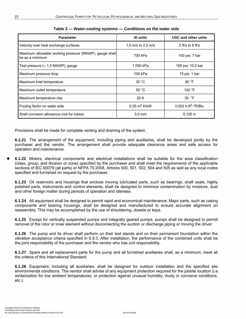
6.1.20 Unless otherwise specified, water-cooling systems shall be designed for the conditions on the water side as given in Table 2.
Copyright American Petroleum Institute Provided by IHS under license with API
Not for ResaleNo reproduction or networking permitted without license from IHS
--`,,```,,,,````-`-`,,`,,`,`,,`---
22 CENTRIFUGAL PUMPS FOR PETROLEUM, PETROCHEMICAL AND NATURAL GAS INDUSTRIES
Table 2 — Water-cooling systems — Conditions on the water side
Parameter SI units USC and other units
Velocity over heat exchange surfaces 1,5 m/s to 2,5 m/s 5 ft/s to 8 ft/s
Maximum allowable working pressure (MAWP), gauge shall be as a minimum
700 kPa 100 psi; 7 bar
Test pressure ( 1,5 MAWP), gauge 1 050 kPa 150 psi; 10,5 bar
Maximum pressure drop 100 kPa 15 psi, 1 bar
Maximum inlet temperature 30 °C 90 °F
Maximum outlet temperature 50 °C 120 °F
Maximum temperature rise 20 K 30 °F
Fouling factor on water side 0,35 m2 K/kW 0,002 h-ft2-°R/Btu
Shell corrosion allowance (not for tubes) 3,0 mm 0,125 in
Provisions shall be made for complete venting and draining of the system.
6.1.21 The arrangement of the equipment, including piping and auxiliaries, shall be developed jointly by the purchaser and the vendor. The arrangement shall provide adequate clearance areas and safe access for operation and maintenance.
6.1.22 Motors, electrical components and electrical installations shall be suitable for the area classification (class, group, and division or zone) specified by the purchaser and shall meet the requirements of the applicable sections of IEC 60079 (all parts) or NFPA 70:2008, Articles 500, 501, 502, 504 and 505 as well as any local codes specified and furnished on request by the purchaser.
6.1.23 Oil reservoirs and housings that enclose moving lubricated parts, such as bearings, shaft seals, highly polished parts, instruments and control elements, shall be designed to minimize contamination by moisture, dust and other foreign matter during periods of operation and idleness.
6.1.24 All equipment shall be designed to permit rapid and economical maintenance. Major parts, such as casing components and bearing housings, shall be designed and manufactured to ensure accurate alignment on reassembly. This may be accomplished by the use of shouldering, dowels or keys.
6.1.25 Except for vertically suspended pumps and integrally geared pumps, pumps shall be designed to permit removal of the rotor or inner element without disconnecting the suction or discharge piping or moving the driver.
6.1.26 The pump and its driver shall perform on their test stands and on their permanent foundation within the vibration acceptance criteria specified in 6.9.3. After installation, the performance of the combined units shall be the joint responsibility of the purchaser and the vendor who has unit responsibility.
6.1.27 Spare and all replacement parts for the pump and all furnished auxiliaries shall, as a minimum, meet all the criteria of this International Standard.
6.1.28 Equipment, including all auxiliaries, shall be designed for outdoor installation and the specified site environmental conditions. The vendor shall advise of any equipment protection required for the jobsite location (i.e. winterization for low ambient temperatures, or protection against unusual humidity, dusty or corrosive conditions, etc.).
Copyright American Petroleum Institute Provided by IHS under license with API
Not for ResaleNo reproduction or networking permitted without license from IHS
--`,,```,,,,````-`-`,,`,,`,`,,`---

API STANDARD 610/ISO 13709 23
6.1.29 Bolting and threads
6.1.29.1 The details of threading shall conform to ISO 261, ISO 262, ISO 724 and ISO 965 (all parts), or to ANSI/ASME B1.1. The vendor shall advise the type of bolting used on the pump.
6.1.29.2 When ANSI/ASME B1.1 threads have been specified, the thread series shall be the variable-pitch series UNC. The threads shall be Class 2 for bolting, studs and nuts. For other threads and nuts, they shall be Class 2 or 3.
6.1.29.3 When ISO 261 and ISO 262 have been specified, the thread series shall be coarse. Threads shall be Class 6g for bolting and studs, and Class 6H for nuts.
6.1.30 Commercial fasteners shall be manufactured in accordance with the requirements of ANSI/ASME B18.18.2M or shall be procured from distributors having quality plans in accordance with ANSI/ASME B18.18.2M.
6.1.31 Adequate clearance shall be provided at all bolting locations to permit the use of socket or box wrenches.
6.1.32 Unless otherwise specified or agreed, studs shall be supplied on all main casing joints, and all other joints and connections shall be supplied with external hexagon-head bolting.
6.1.33 Fasteners (excluding washers and headless set-screws) shall have the material grade and manufacturer's identification symbols applied to one end of studs 10 mm (3/8 in) in diameter and larger and to the heads of bolts 6 mm (1/4 in) in diameter and larger. If the available area is inadequate, the grade symbol may be marked on one end and the manufacturer's identification symbol marked on the other end. Studs shall be marked on the exposed end.
NOTE A set-screw is a headless screw with a hexagonal socket in one end.
6.1.34 Pressure casing fasteners shall be not less than 12 mm (0,5 in) diameter.
6.2 Pump types
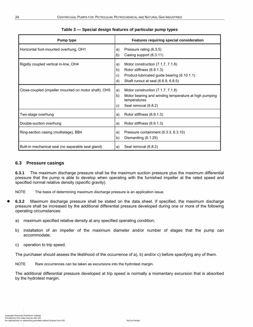
The pump types listed in Table 3 have special design features and shall be furnished only if specified by the purchaser and if the manufacturer has proven experience for the specific application. Table 3 lists the features requiring special consideration for these pump types, and gives in parentheses the relevant subclause(s) of this International Standard.
Copyright American Petroleum Institute Provided by IHS under license with API
Not for ResaleNo reproduction or networking permitted without license from IHS
--`,,```,,,,````-`-`,,`,,`,`,,`---
24 CENTRIFUGAL PUMPS FOR PETROLEUM, PETROCHEMICAL AND NATURAL GAS INDUSTRIES
Table 3 — Special design features of particular pump types
Pump type Features requiring special consideration
Horizontal foot-mounted overhung, OH1 a) Pressure rating (6.3.5)
b) Casing support (6.3.11)
Rigidly coupled vertical in-line, OH4 a) Motor construction (7.1.7, 7.1.8)
b) Rotor stiffness (6.9.1.3)
c) Product-lubricated guide bearing (6.10.1.1)
d) Shaft runout at seal (6.6.9, 6.8.5)
Close-coupled (impeller mounted on motor shaft), OH5 a) Motor construction (7.1.7, 7.1.8)
b) Motor bearing and winding temperature at high pumping temperatures
c) Seal removal (6.8.2)
Two-stage overhung a) Rotor stiffness (6.9.1.3)
Double-suction overhung a) Rotor stiffness (6.9.1.3)
Ring-section casing (multistage), BB4 a) Pressure containment (6.3.3, 6.3.10)
b) Dismantling (6.1.25)
Built-in mechanical seal (no separable seal gland) a) Seal removal (6.8.2)
6.3 Pressure casings
6.3.1 The maximum discharge pressure shall be the maximum suction pressure plus the maximum differential pressure that the pump is able to develop when operating with the furnished impeller at the rated speed and specified normal relative density (specific gravity).
NOTE The basis of determining maximum discharge pressure is an application issue.
6.3.2 Maximum discharge pressure shall be stated on the data sheet. If specified, the maximum discharge pressure shall be increased by the additional differential pressure developed during one or more of the following operating circumstances:
a) maximum specified relative density at any specified operating condition;
b) installation of an impeller of the maximum diameter and/or number of stages that the pump can accommodate;
c) operation to trip speed.
The purchaser should assess the likelihood of the occurrence of a), b) and/or c) before specifying any of them.
NOTE Rare occurrences can be taken as excursions into the hydrotest margin.
The additional differential pressure developed at trip speed is normally a momentary excursion that is absorbed by the hydrotest margin.
Copyright American Petroleum Institute Provided by IHS under license with API
Not for ResaleNo reproduction or networking permitted without license from IHS
--`,,```,,,,````-`-`,,`,,`,`,,`---
API STANDARD 610/ISO 13709 25
6.3.3 The pressure casing shall be designed to
a) operate without leakage or internal contact between rotating and stationary components while subject simultaneously to the MAWP (and maximum operating temperature) and the worst-case combination of twice the allowable nozzle loads of Table 5 applied through each nozzle;
b) withstand the hydrostatic test (see 8.3.2).
NOTE The twice-nozzle-load requirement is a pressure-casing design criterion. Allowable nozzle loads for piping designers are the values given in Table 5, which, in addition to pressure casing design, include other factors that affect allowable nozzle loads, such as casing support and baseplate stiffness.
6.3.4 The tensile stress used in the design of the pressure casing for any material shall not exceed 0,25 times the minimum ultimate tensile strength or 0,67 times the minimum yield strength for that material, whichever is lower, across the full range of specified operating temperatures. For castings, the design tensile stress values shall be multiplied by the appropriate casting factor, as shown in Table 4. The manufacturer, in his proposal, shall state the source of the material properties from those listed in Table H.2 (i.e. ISO, ASTM, UNS, EN, JIS), as well as the casting factors applied. National material standards other than those listed in Table H.2, may be used with specific purchaser approval.
NOTE 1 In general, the criteria in 6.3.3 result in deflection (strain) being the determining consideration in the design of pump casings with respect to pressure retention and nozzle loads. Ultimate tensile or yield strength is seldom the limiting factor.
NOTE 2 For bolting, the allowable tensile stress is used to determine the total bolting area based on hydrostatic load or gasket preload. It is recognized that to provide the initial load required to obtain a reliable bolted joint, it is necessary that the bolting be tightened to produce a tensile stress higher than the design tensile stress. Values in the range of 0,7 to 0,9 times yield are common.
Table 4 — Casting factors
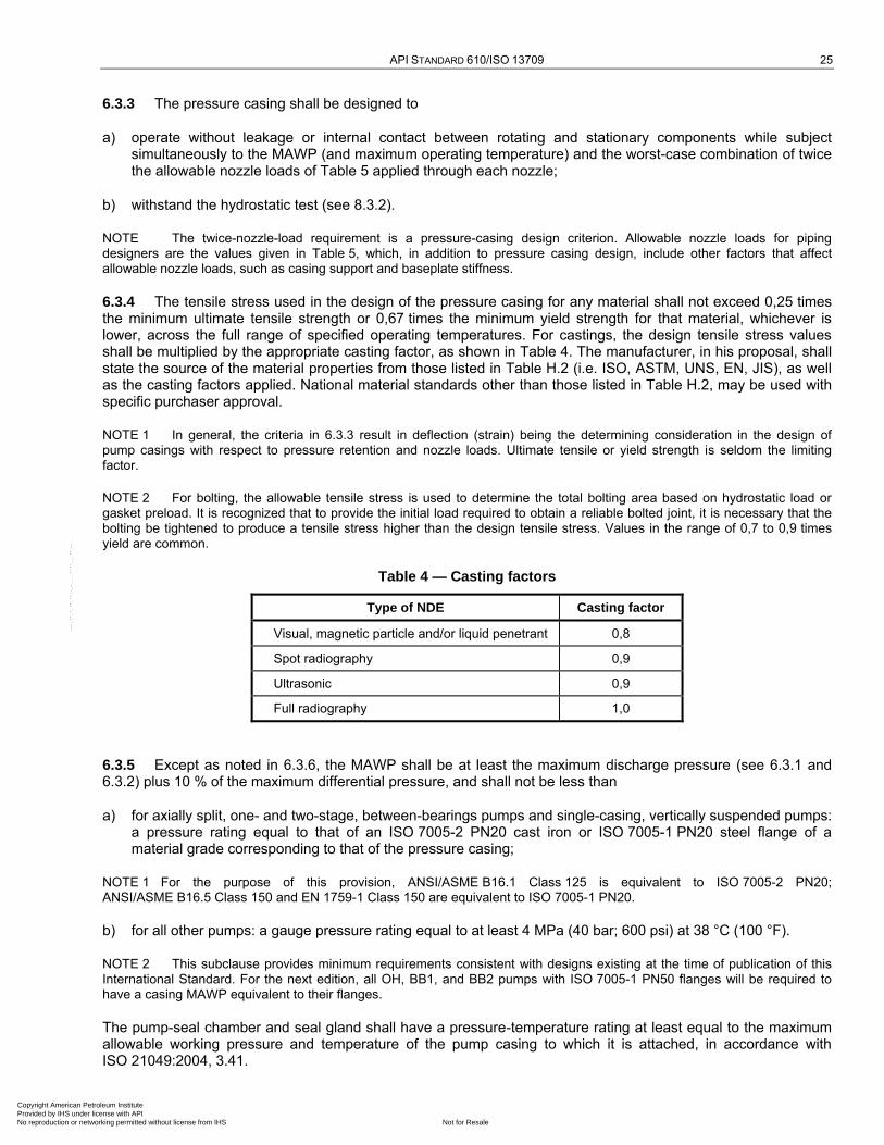
Type of NDE Casting factor
Visual, magnetic particle and/or liquid penetrant 0,8
Spot radiography 0,9
Ultrasonic 0,9
Full radiography 1,0
6.3.5 Except as noted in 6.3.6, the MAWP shall be at least the maximum discharge pressure (see 6.3.1 and 6.3.2) plus 10 % of the maximum differential pressure, and shall not be less than
a) for axially split, one- and two-stage, between-bearings pumps and single-casing, vertically suspended pumps: a pressure rating equal to that of an ISO 7005-2 PN20 cast iron or ISO 7005-1 PN20 steel flange of a material grade corresponding to that of the pressure casing;
NOTE 1 For the purpose of this provision, ANSI/ASME B16.1 Class 125 is equivalent to ISO 7005-2 PN20; ANSI/ASME B16.5 Class 150 and EN 1759-1 Class 150 are equivalent to ISO 7005-1 PN20.
b) for all other pumps: a gauge pressure rating equal to at least 4 MPa (40 bar; 600 psi) at 38 °C (100 °F).
NOTE 2 This subclause provides minimum requirements consistent with designs existing at the time of publication of this International Standard. For the next edition, all OH, BB1, and BB2 pumps with ISO 7005-1 PN50 flanges will be required to have a casing MAWP equivalent to their flanges.
The pump-seal chamber and seal gland shall have a pressure-temperature rating at least equal to the maximum allowable working pressure and temperature of the pump casing to which it is attached, in accordance with ISO 21049:2004, 3.41.
Copyright American Petroleum Institute Provided by IHS under license with API
Not for ResaleNo reproduction or networking permitted without license from IHS
--`,,```,,,,````-`-`,,`,,`,`,,`---
26 CENTRIFUGAL PUMPS FOR PETROLEUM, PETROCHEMICAL AND NATURAL GAS INDUSTRIES
NOTE 3 The 10 % differential pressure margin is intended to accommodate head increases (6.1.4), higher speed in variable-speed pumps (6.1.5) and head (testing) tolerance [see 8.3.3.3 b)].
NOTE 4 For the purposes of this provision, ANSI/ASME B16.5 Class 300 and EN 1759-1 Class 300 are equivalent to ISO 7005-1 PN50.
6.3.6 Unless otherwise specified, vertically suspended, double-casing, integral gear-driven (type OH6) and horizontal, multistage pumps may be designed for dual pressure ratings. If specified, suction regions shall be designed for the same MAWP as the discharge section. The purchaser should consider installation of relief valves on the suction side of such installations.
6.3.7 The pressure casing shall be designed with a corrosion allowance to meet the requirements of 6.1.1. Unless otherwise specified, the minimum corrosion allowance shall be 3 mm (0,12 in).
The vendor is encouraged to propose alternative corrosion allowances for consideration if materials of construction with superior corrosion resistance are employed and if they result in lower cost without affecting safety and reliability.
6.3.8 The inner casing of double-casing pumps shall be designed to withstand the maximum differential pressure or 350 kPa (3,5 bar; 50 psi), whichever is greater.
6.3.9 Unless otherwise specified, pumps with radially split casings are required in services for any of the following operating conditions:
a) pumping temperature of 200 °C (400 °F) or higher (a lower temperature limit should be considered if thermal shock is probable);
b) liquids with a relative density of less than 0,7 at the specified pumping temperature;
c) liquids at a rated discharge gauge pressure above 10 MPa (100 bar; 1 450 psi).
Axially split casings have been used successfully beyond the limits given above, generally for off-plot applications at higher pressure or lower relative density (specific gravity). The success of such applications depends on the margin between design pressure and rated pressure, the manufacturer's experience with similar applications, the design and manufacture of the split joint, and the user's ability to correctly remake the split joint in the field. The purchaser should take these factors into account before specifying an axially split casing for conditions beyond the above limits.
6.3.10 Radially split casings shall have metal-to-metal fits, with confined controlled-compression gaskets, such as an O-ring or a spiral-wound type. Gaskets other than spiral-wound may be proposed and furnished if proven suitable for service and approved by the purchaser. Radially split pressure casing joints and bolting shall be designed to seat a spiral-wound gasket (see 9.3.2.3 for VS type pumps).
NOTE Table H.1 shows only spiral-wound gaskets for casing joints. Spiral-wound gaskets are generally preferred because they are perceived by users to have had better availability, are more conducive to material identification, have a broader chemical compatibility and temperature range, contact a wider sealing surface (are less susceptible to leakage because of sealing surface irregularities) and are easier to handle and store than O-rings. ISO 21049 and
ANSI/API Std 682/ISO 21049, specifically require O-ring gaskets on low-temperature [ 175 °C (350 °F)] pressure-seal gland
plates.
6.3.11 Centreline-supported pump casings shall be used for all horizontal pumps except as allowed in 9.2.1.2.
6.3.12 O-ring sealing surfaces, including all grooves and bores, shall have a maximum surface roughness average value, Ra, of 1,6 µm (63 µin) for static O-rings and 0,8 µm (32 µin) for the surface against which dynamic O-rings slide. Bores shall have a minimum 3 mm (0,12 in) radius or a minimum 1,5 mm (0,06 in) chamfered lead-in for static O-rings and a minimum 2 mm (0,08 in) chamfered lead-in for dynamic O-rings. Chamfers shall have a maximum angle of 30°.
6.3.13 Jackscrews shall be provided to facilitate disassembly of the casing. One of the contacting faces shall be relieved (counterbored or recessed) to prevent a leaking joint or an improper fit caused by marring of the face.
Copyright American Petroleum Institute Provided by IHS under license with API
Not for ResaleNo reproduction or networking permitted without license from IHS
--`,,```,,,,````-`-`,,`,,`,`,,`---
API STANDARD 610/ISO 13709 27
6.3.14 The use of threaded holes in pressure parts shall be minimized. To prevent leakage in pressure sections of casings, metal, equal in thickness to at least half the nominal bolt or stud diameter, plus the allowance for corrosion, shall be left around and below the bottom of drilled and threaded holes.
6.3.15 Internal bolting shall be of a material fully resistant to corrosive attack by the pumped liquid.
6.3.16 If the manufacture of cast pressure-casing parts requires the use of openings for core support, core removal or waterway inspection and cleaning, these openings shall be designed so they can be closed by welding, using an appropriate, qualified weld procedure, during the completion of casting manufacture.
6.4 Nozzles and pressure casing connections
6.4.1 Casing opening sizes
6.4.1.1 Openings for nozzles and other pressure casing connections shall be standard pipe sizes. Openings of DN 32, DN 65, DN 90, DN 125, DN 175 and DN 225 (NPS 1 1/4, NPS 2 1/2, NPS 3 1/2, NPS 5, NPS 7 and NPS 9) shall not be used.
6.4.1.2 Casing connections other than suction and discharge nozzles shall be at least DN 15 (NPS 1/2) for pumps with discharge nozzle openings DN 50 (NPS 2) and smaller. Connections shall be at least DN 20 (NPS 3/4) for pumps with discharge nozzle openings DN 80 (NPS 3) and larger, except that connections for seal flush piping and gauges may be DN 15 (NPS 1/2) regardless of pump size.
6.4.2 Suction and discharge nozzles
6.4.2.1 Suction and discharge nozzles shall be flanged, except those on pumps with forged casings, which shall be flanged or machined and studded. One- and two-stage pumps shall have suction and discharge flanges of equal rating. If the pump is supplied with machined and studded connections, the pump vendor shall provide drawings showing the dimensions of break-out spool pieces to allow the pump to be conveniently removed from the piping.
6.4.2.2 Cast iron flanges shall be flat-faced and, except as noted in 6.4.2.4, conform to the dimensional requirements of ISO 7005-2 and the flange finish requirements of ANSI/ASME B16.1 or ANSI/ASME B16.42. PN20 (Class 125) flanges shall have a minimum thickness equal to that of PN40 (Class 250) flanges for sizes DN 200 (NPS 8) and smaller.
6.4.2.3 Flanges other than cast iron shall, as a minimum requirement, conform to the dimensional requirements of ISO 7005-1 PN50 except as noted in 6.4.2.4 and the flange finish requirements of ANSI/ASME B16.5 or ANSI/ASME B16.47.
NOTE For the purpose of this provision, ANSI/ASME B16.5 Class 300 and ANSI/ASME B16.47 Class 300 and EN 1759-1 Class 300 are equivalent to ISO 7005-1 PN50.
6.4.2.4 Flanges in all materials that are thicker or have a larger outside diameter than required by the relevant ISO or ASME standards in this International Standard are acceptable. Non-standard (oversized) flanges shall be completely dimensioned on the arrangement drawing. If oversized flanges require studs or bolts of non-standard length, this requirement shall be identified on the arrangement drawing.
6.4.2.5 Flanges shall be full faced or spot faced on the back and shall be designed for through bolting, except for jacketed casings.
6.4.2.6 To minimize nozzle loading and facilitate installation of piping, machined faces of pump flanges shall be parallel to the plane as shown on the general arrangement drawing within 0,5°. Bolt holes or studs shall straddle centrelines parallel to the main axes of the pump.
6.4.3 Auxiliary connections
6.4.3.1 All auxiliary connections to the pressure casing, except the seal gland, shall terminate in a flange meeting the requirements of 6.4.2.2. or 6.4.2.3. These connections shall be integrally flanged, socket welded or
Copyright American Petroleum Institute Provided by IHS under license with API
Not for ResaleNo reproduction or networking permitted without license from IHS
--`,,```,,,,````-`-`,,`,,`,`,,`---
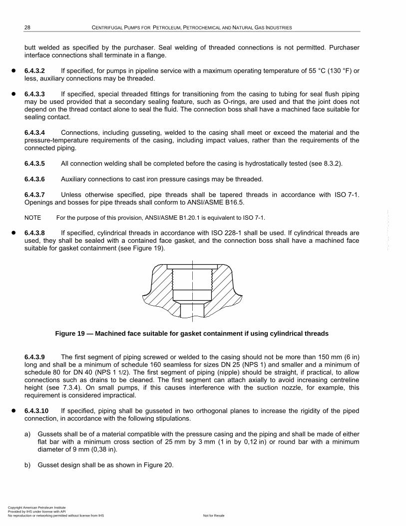
28 CENTRIFUGAL PUMPS FOR PETROLEUM, PETROCHEMICAL AND NATURAL GAS INDUSTRIES
butt welded as specified by the purchaser. Seal welding of threaded connections is not permitted. Purchaser interface connections shall terminate in a flange.
6.4.3.2 If specified, for pumps in pipeline service with a maximum operating temperature of 55 °C (130 °F) or less, auxiliary connections may be threaded.
6.4.3.3 If specified, special threaded fittings for transitioning from the casing to tubing for seal flush piping may be used provided that a secondary sealing feature, such as O-rings, are used and that the joint does not depend on the thread contact alone to seal the fluid. The connection boss shall have a machined face suitable for sealing contact.
6.4.3.4 Connections, including gusseting, welded to the casing shall meet or exceed the material and the pressure-temperature requirements of the casing, including impact values, rather than the requirements of the connected piping.
6.4.3.5 All connection welding shall be completed before the casing is hydrostatically tested (see 8.3.2).
6.4.3.6 Auxiliary connections to cast iron pressure casings may be threaded.
6.4.3.7 Unless otherwise specified, pipe threads shall be tapered threads in accordance with ISO 7-1. Openings and bosses for pipe threads shall conform to ANSI/ASME B16.5.
NOTE For the purpose of this provision, ANSI/ASME B1.20.1 is equivalent to ISO 7-1.
6.4.3.8 If specified, cylindrical threads in accordance with ISO 228-1 shall be used. If cylindrical threads are used, they shall be sealed with a contained face gasket, and the connection boss shall have a machined face suitable for gasket containment (see Figure 19).
Figure 19 — Machined face suitable for gasket containment if using cylindrical threads
6.4.3.9 The first segment of piping screwed or welded to the casing should not be more than 150 mm (6 in) long and shall be a minimum of schedule 160 seamless for sizes DN 25 (NPS 1) and smaller and a minimum of schedule 80 for DN 40 (NPS 1 1/2). The first segment of piping (nipple) should be straight, if practical, to allow connections such as drains to be cleaned. The first segment can attach axially to avoid increasing centreline height (see 7.3.4). On small pumps, if this causes interference with the suction nozzle, for example, this requirement is considered impractical.
6.4.3.10 If specified, piping shall be gusseted in two orthogonal planes to increase the rigidity of the piped connection, in accordance with the following stipulations.
a) Gussets shall be of a material compatible with the pressure casing and the piping and shall be made of either flat bar with a minimum cross section of 25 mm by 3 mm (1 in by 0,12 in) or round bar with a minimum diameter of 9 mm (0,38 in).
b) Gusset design shall be as shown in Figure 20.
Copyright American Petroleum Institute Provided by IHS under license with API
Not for ResaleNo reproduction or networking permitted without license from IHS
--`,,```,,,,````-`-`,,`,,`,`,,`---
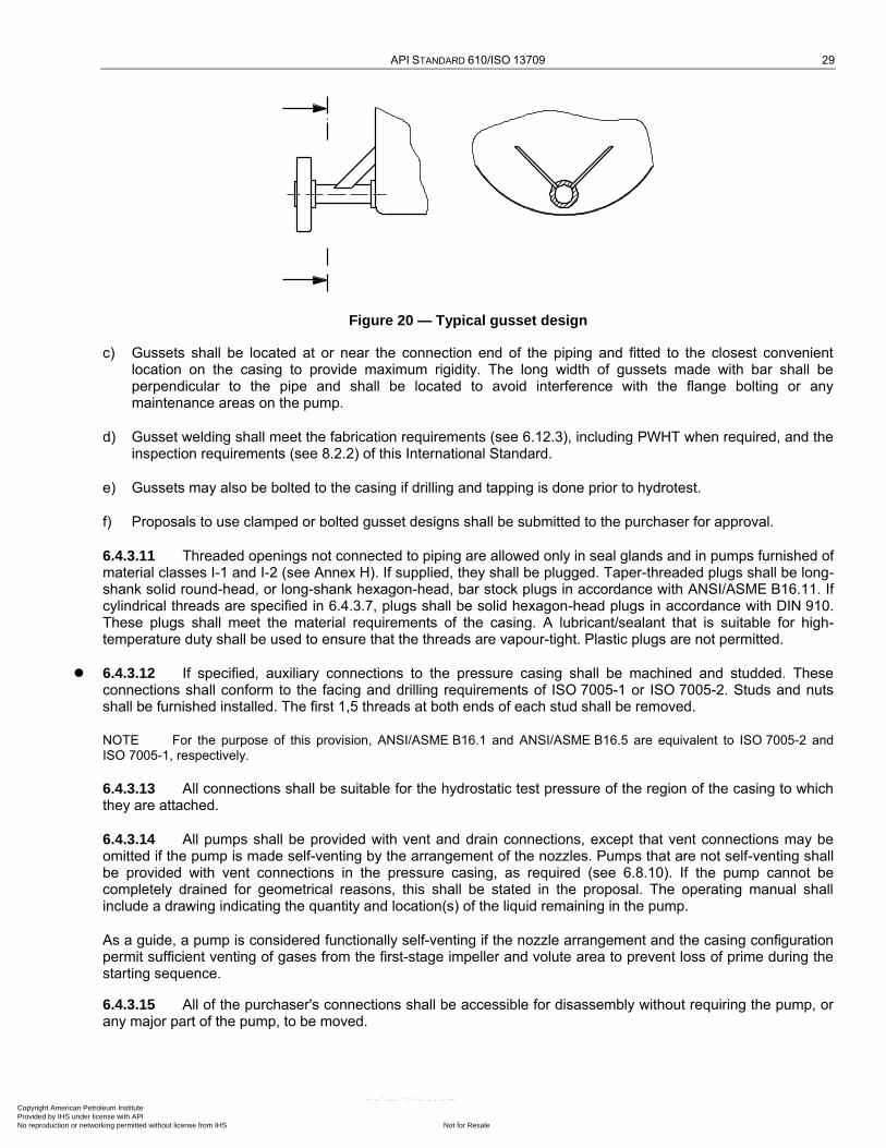
API STANDARD 610/ISO 13709 29
Figure 20 — Typical gusset design
c) Gussets shall be located at or near the connection end of the piping and fitted to the closest convenient location on the casing to provide maximum rigidity. The long width of gussets made with bar shall be perpendicular to the pipe and shall be located to avoid interference with the flange bolting or any maintenance areas on the pump.
d) Gusset welding shall meet the fabrication requirements (see 6.12.3), including PWHT when required, and the inspection requirements (see 8.2.2) of this International Standard.
e) Gussets may also be bolted to the casing if drilling and tapping is done prior to hydrotest.
f) Proposals to use clamped or bolted gusset designs shall be submitted to the purchaser for approval.
6.4.3.11 Threaded openings not connected to piping are allowed only in seal glands and in pumps furnished of material classes I-1 and I-2 (see Annex H). If supplied, they shall be plugged. Taper-threaded plugs shall be long-shank solid round-head, or long-shank hexagon-head, bar stock plugs in accordance with ANSI/ASME B16.11. If cylindrical threads are specified in 6.4.3.7, plugs shall be solid hexagon-head plugs in accordance with DIN 910. These plugs shall meet the material requirements of the casing. A lubricant/sealant that is suitable for high-temperature duty shall be used to ensure that the threads are vapour-tight. Plastic plugs are not permitted.
6.4.3.12 If specified, auxiliary connections to the pressure casing shall be machined and studded. These connections shall conform to the facing and drilling requirements of ISO 7005-1 or ISO 7005-2. Studs and nuts shall be furnished installed. The first 1,5 threads at both ends of each stud shall be removed.
NOTE For the purpose of this provision, ANSI/ASME B16.1 and ANSI/ASME B16.5 are equivalent to ISO 7005-2 and ISO 7005-1, respectively.
6.4.3.13 All connections shall be suitable for the hydrostatic test pressure of the region of the casing to which they are attached.
6.4.3.14 All pumps shall be provided with vent and drain connections, except that vent connections may be omitted if the pump is made self-venting by the arrangement of the nozzles. Pumps that are not self-venting shall be provided with vent connections in the pressure casing, as required (see 6.8.10). If the pump cannot be completely drained for geometrical reasons, this shall be stated in the proposal. The operating manual shall include a drawing indicating the quantity and location(s) of the liquid remaining in the pump.
As a guide, a pump is considered functionally self-venting if the nozzle arrangement and the casing configuration permit sufficient venting of gases from the first-stage impeller and volute area to prevent loss of prime during the starting sequence.
6.4.3.15 All of the purchaser's connections shall be accessible for disassembly without requiring the pump, or any major part of the pump, to be moved.
Copyright American Petroleum Institute Provided by IHS under license with API
Not for ResaleNo reproduction or networking permitted without license from IHS
--`,,```,,,,````-`-`,,`,,`,`,,`---
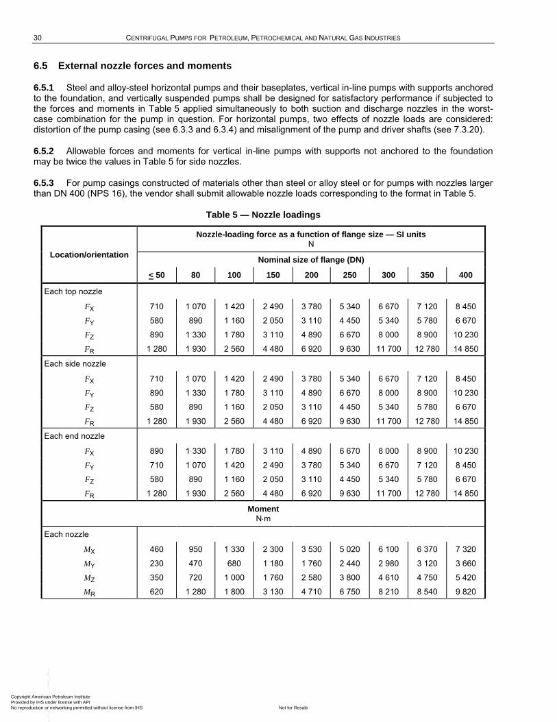
30 CENTRIFUGAL PUMPS FOR PETROLEUM, PETROCHEMICAL AND NATURAL GAS INDUSTRIES
6.5 External nozzle forces and moments
6.5.1 Steel and alloy-steel horizontal pumps and their baseplates, vertical in-line pumps with supports anchored to the foundation, and vertically suspended pumps shall be designed for satisfactory performance if subjected to the forces and moments in Table 5 applied simultaneously to both suction and discharge nozzles in the worst-case combination for the pump in question. For horizontal pumps, two effects of nozzle loads are considered: distortion of the pump casing (see 6.3.3 and 6.3.4) and misalignment of the pump and driver shafts (see 7.3.20).
6.5.2 Allowable forces and moments for vertical in-line pumps with supports not anchored to the foundation may be twice the values in Table 5 for side nozzles.
6.5.3 For pump casings constructed of materials other than steel or alloy steel or for pumps with nozzles larger than DN 400 (NPS 16), the vendor shall submit allowable nozzle loads corresponding to the format in Table 5.
Table 5 — Nozzle loadings
Location/orientation
Nozzle-loading force as a function of flange size — SI units N
Nominal size of flange (DN)
< 50 80 100 150 200 250 300 350 400
Each top nozzle
FX 710 1 070 1 420 2 490 3 780 5 340 6 670 7 120 8 450
FY 580 890 1 160 2 050 3 110 4 450 5 340 5 780 6 670
FZ 890 1 330 1 780 3 110 4 890 6 670 8 000 8 900 10 230
FR 1 280 1 930 2 560 4 480 6 920 9 630 11 700 12 780 14 850
Each side nozzle
FX 710 1 070 1 420 2 490 3 780 5 340 6 670 7 120 8 450
FY 890 1 330 1 780 3 110 4 890 6 670 8 000 8 900 10 230
FZ 580 890 1 160 2 050 3 110 4 450 5 340 5 780 6 670
FR 1 280 1 930 2 560 4 480 6 920 9 630 11 700 12 780 14 850
Each end nozzle
FX 890 1 330 1 780 3 110 4 890 6 670 8 000 8 900 10 230
FY 710 1 070 1 420 2 490 3 780 5 340 6 670 7 120 8 450
FZ 580 890 1 160 2 050 3 110 4 450 5 340 5 780 6 670
FR 1 280 1 930 2 560 4 480 6 920 9 630 11 700 12 780 14 850
Moment N m
Each nozzle
MX 460 950 1 330 2 300 3 530 5 020 6 100 6 370 7 320
MY 230 470 680 1 180 1 760 2 440 2 980 3 120 3 660
MZ 350 720 1 000 1 760 2 580 3 800 4 610 4 750 5 420
MR 620 1 280 1 800 3 130 4 710 6 750 8 210 8 540 9 820
Copyright American Petroleum Institute Provided by IHS under license with API
Not for ResaleNo reproduction or networking permitted without license from IHS
--`,,```,,,,````-`-`,,`,,`,`,,`---
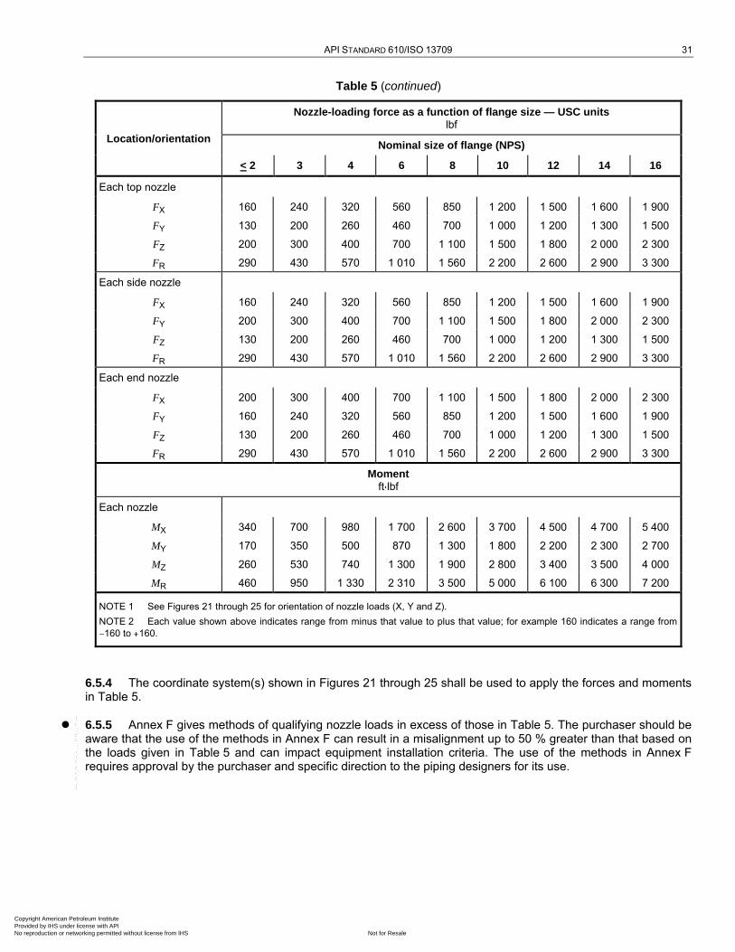
API STANDARD 610/ISO 13709 31
Table 5 (continued)
Location/orientation
Nozzle-loading force as a function of flange size — USC units lbf
Nominal size of flange (NPS)
< 2 3 4 6 8 10 12 14 16
Each top nozzle
FX 160 240 320 560 850 1 200 1 500 1 600 1 900
FY 130 200 260 460 700 1 000 1 200 1 300 1 500
FZ 200 300 400 700 1 100 1 500 1 800 2 000 2 300
FR 290 430 570 1 010 1 560 2 200 2 600 2 900 3 300
Each side nozzle
FX 160 240 320 560 850 1 200 1 500 1 600 1 900
FY 200 300 400 700 1 100 1 500 1 800 2 000 2 300
FZ 130 200 260 460 700 1 000 1 200 1 300 1 500
FR 290 430 570 1 010 1 560 2 200 2 600 2 900 3 300
Each end nozzle
FX 200 300 400 700 1 100 1 500 1 800 2 000 2 300
FY 160 240 320 560 850 1 200 1 500 1 600 1 900
FZ 130 200 260 460 700 1 000 1 200 1 300 1 500
FR 290 430 570 1 010 1 560 2 200 2 600 2 900 3 300
Moment ft lbf
Each nozzle
MX 340 700 980 1 700 2 600 3 700 4 500 4 700 5 400
MY 170 350 500 870 1 300 1 800 2 200 2 300 2 700
MZ 260 530 740 1 300 1 900 2 800 3 400 3 500 4 000
MR 460 950 1 330 2 310 3 500 5 000 6 100 6 300 7 200
NOTE 1 See Figures 21 through 25 for orientation of nozzle loads (X, Y and Z).
NOTE 2 Each value shown above indicates range from minus that value to plus that value; for example 160 indicates a range from
160 to 160.
6.5.4 The coordinate system(s) shown in Figures 21 through 25 shall be used to apply the forces and moments in Table 5.
6.5.5 Annex F gives methods of qualifying nozzle loads in excess of those in Table 5. The purchaser should be aware that the use of the methods in Annex F can result in a misalignment up to 50 % greater than that based on the loads given in Table 5 and can impact equipment installation criteria. The use of the methods in Annex F requires approval by the purchaser and specific direction to the piping designers for its use.
Copyright American Petroleum Institute Provided by IHS under license with API
Not for ResaleNo reproduction or networking permitted without license from IHS
--`,,```,,,,````-`-`,,`,,`,`,,`---
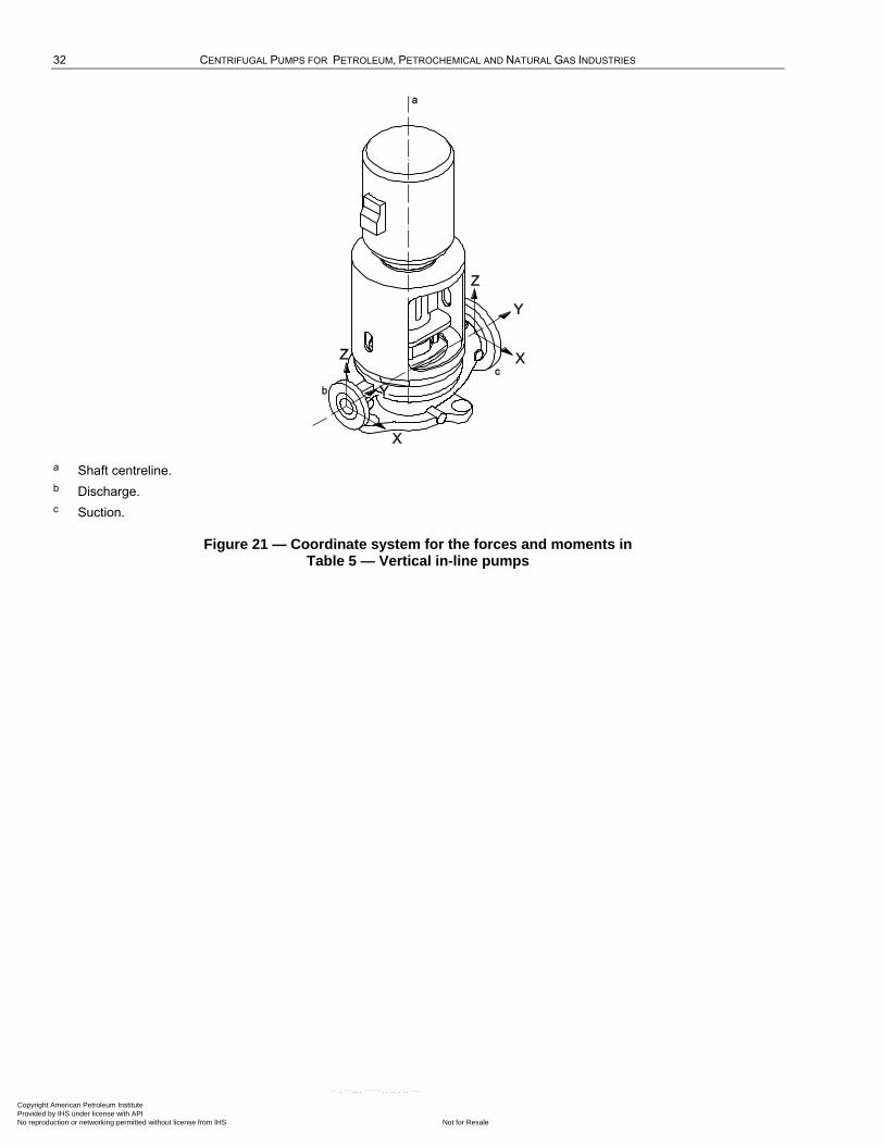
32 CENTRIFUGAL PUMPS FOR PETROLEUM, PETROCHEMICAL AND NATURAL GAS INDUSTRIES
a Shaft centreline.
b Discharge.
c Suction.
Figure 21 — Coordinate system for the forces and moments in Table 5 — Vertical in-line pumps
Copyright American Petroleum Institute Provided by IHS under license with API
Not for ResaleNo reproduction or networking permitted without license from IHS
--`,,```,,,,````-`-`,,`,,`,`,,`---
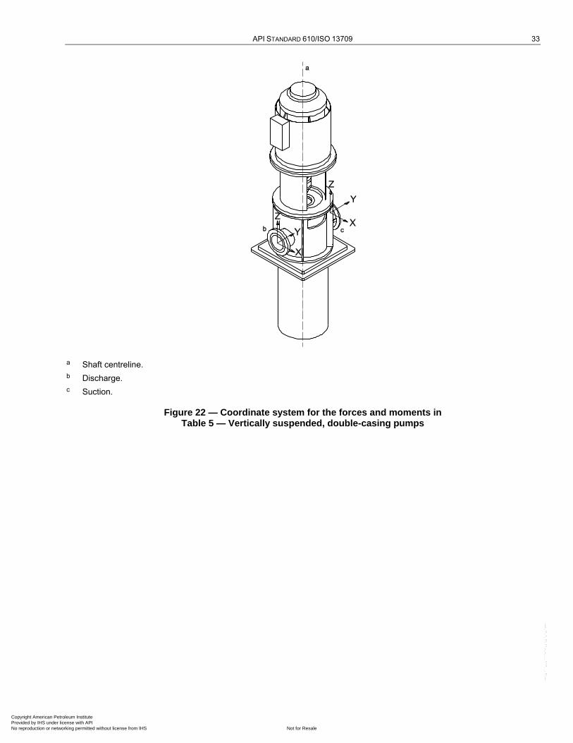
API STANDARD 610/ISO 13709 33
a Shaft centreline.
b Discharge.
c Suction.
Figure 22 — Coordinate system for the forces and moments in Table 5 — Vertically suspended, double-casing pumps
Copyright American Petroleum Institute Provided by IHS under license with API
Not for ResaleNo reproduction or networking permitted without license from IHS
--`,,```,,,,````-`-`,,`,,`,`,,`---
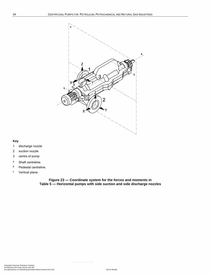
34 CENTRIFUGAL PUMPS FOR PETROLEUM, PETROCHEMICAL AND NATURAL GAS INDUSTRIES
Key
1 discharge nozzle
2 suction nozzle
3 centre of pump
a Shaft centreline.
b Pedestal centreline.
c Vertical plane.
Figure 23 — Coordinate system for the forces and moments in Table 5 — Horizontal pumps with side suction and side discharge nozzles
Copyright American Petroleum Institute Provided by IHS under license with API
Not for ResaleNo reproduction or networking permitted without license from IHS
--`,,```,,,,````-`-`,,`,,`,`,,`---
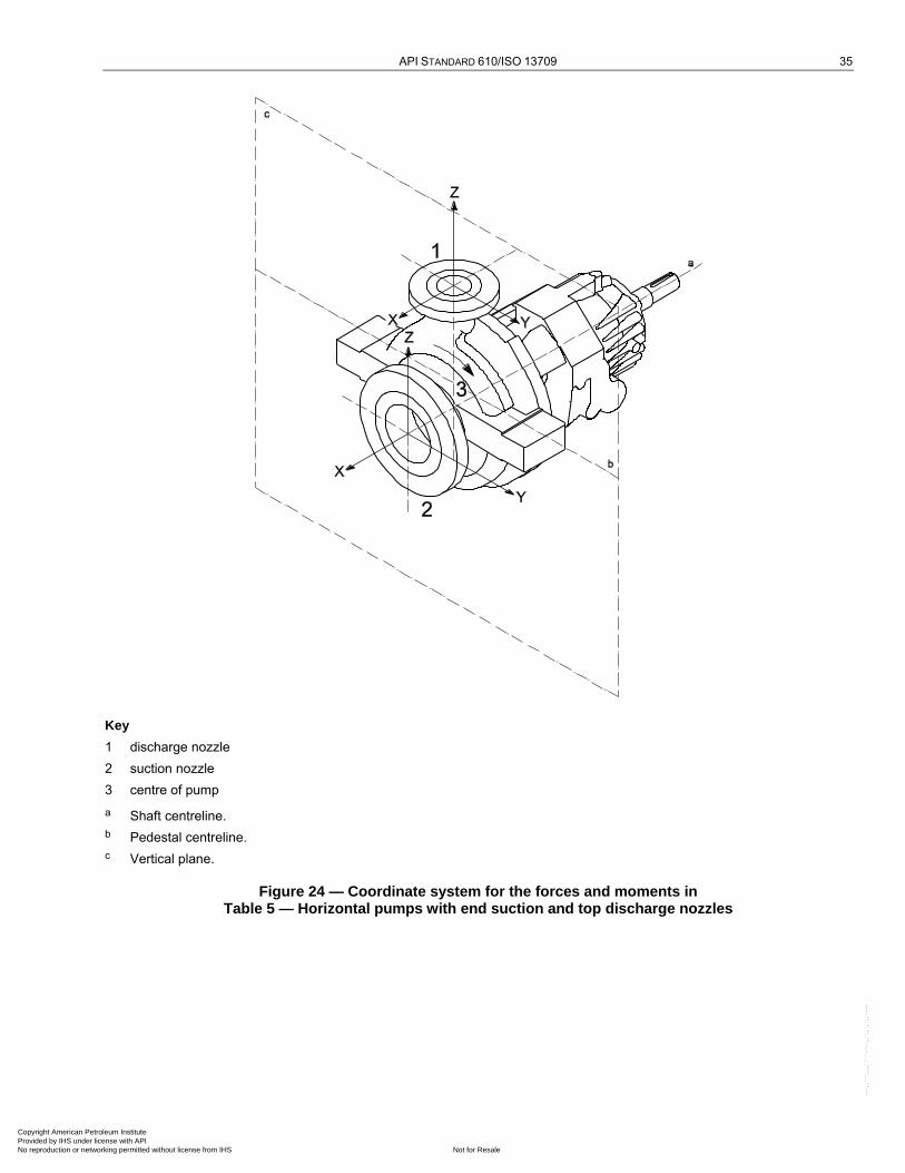
API STANDARD 610/ISO 13709 35
Key
1 discharge nozzle
2 suction nozzle
3 centre of pump
a Shaft centreline.
b Pedestal centreline.
c Vertical plane.
Figure 24 — Coordinate system for the forces and moments in Table 5 — Horizontal pumps with end suction and top discharge nozzles
Copyright American Petroleum Institute Provided by IHS under license with API
Not for ResaleNo reproduction or networking permitted without license from IHS
--`,,```,,,,````-`-`,,`,,`,`,,`---
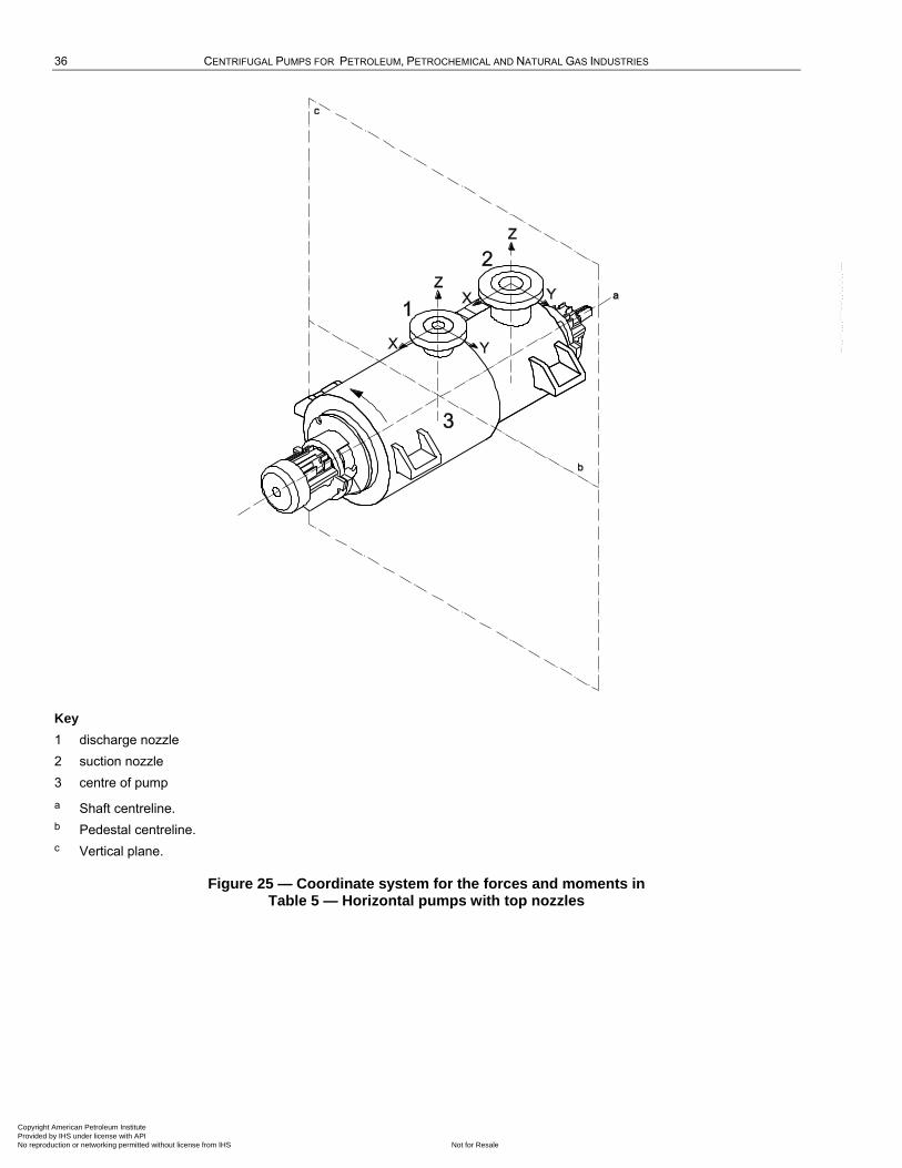
36 CENTRIFUGAL PUMPS FOR PETROLEUM, PETROCHEMICAL AND NATURAL GAS INDUSTRIES
Key
1 discharge nozzle
2 suction nozzle
3 centre of pump
a Shaft centreline.
b Pedestal centreline.
c Vertical plane.
Figure 25 — Coordinate system for the forces and moments in Table 5 — Horizontal pumps with top nozzles
Copyright American Petroleum Institute Provided by IHS under license with API
Not for ResaleNo reproduction or networking permitted without license from IHS
--`,,```,,,,````-`-`,,`,,`,`,,`---
API STANDARD 610/ISO 13709 37
6.6 Rotors
6.6.1 Unless otherwise specified, impellers shall be of the fully enclosed, semi-open or open type.
Enclosed (closed) impellers are less sensitive to axial position and, therefore, preferable for long shaft assemblies where axial displacement due to thermal expansion/contraction or to thrust can be substantial. Semi-open impellers can offer a higher efficiency, due to the elimination of disc friction from one shroud. The running clearances for semi-open impellers in vertical pumps can be adjusted from the coupling or top of the motor, thus possibly restoring efficiency and pump output without disassembly of pump parts. The open impeller is typically of an axial-flow propeller type designed for large capacities at low heads; the open impeller is also used for volute sump pumps with a separate discharge.
6.6.2 Impellers shall be single-piece castings, forgings or fabrications.
NOTE Impellers made as forgings or fabrications have machined waterways, which can offer improved performance for low-specific-speed designs.
6.6.3 Impellers shall be keyed to the shaft. Pinning of impellers to the shaft is not acceptable. With the purchaser's approval, collets may be used in vertically suspended pumps. Overhung impellers shall be secured to the shaft by a cap screw or cap nut that does not expose shaft threads. The securing device shall be threaded to tighten by liquid drag on the impeller during normal rotation, and a positive mechanical locking method (for example a staked and corrosion-resistant set-screw or a tongue-type washer) is required. Cap screws shall have fillets and a reduced-diameter shank to reduce stress concentrations.
6.6.4 All shaft keyways shall have fillet radii in accordance with ISO 3117.
NOTE For the purpose of this provision, ANSI/ASME B17.1 is equivalent to ISO 3117.
6.6.5 Impellers shall have solid hubs. Impellers may be made from a cored pattern if the core is completely filled with a suitable metal that has a melting point of not less than 260 °C (500 °F) for pumps with cast-iron casings and not less than 540 °C (1 000 °F) for pumps with cast-steel casings.
NOTE The requirement to fill cored impeller hubs is intended to minimize the danger to personnel if and when impellers are removed by heating.
6.6.6 For shafts that require sleeve gaskets to pass over threads, at least 1,5 mm (0,06 in) radial clearance shall be provided between the threads and the internal diameter of the gasket, and the diameter transition shall be chamfered in accordance with 6.3.12.
6.6.7 The shaft-to-seal sleeve fit(s) shall be F7/h6 in accordance with ISO 286 (all parts).
6.6.8 Areas of shafts that can be damaged by set-screws shall be relieved to facilitate the removal of sleeves or other components.
6.6.9 Shafts shall be machined and finished throughout their length so that the TIR is not more than 25 µm (0,001 in).
6.6.10 If non-contacting vibration probes are furnished in accordance with 7.4.2.2, the shaft sensing areas (both radial vibration and axial position) for observation by radial vibration probes shall
a) be concentric with the bearing journals;
b) be free from stencil and scribe marks or any other surface discontinuity, such as an oil hole or a keyway, for a minimum distance of one probe tip diameter on each side of the probe;
c) not be metallized, sleeved or plated on rotors of materials that exhibit consistent electrical properties;
d) have a final surface finish of 0,8 µm (32 µin) Ra or smoother, preferably obtained by honing or burnishing;
Copyright American Petroleum Institute Provided by IHS under license with API
Not for ResaleNo reproduction or networking permitted without license from IHS
--`,,```,,,,````-`-`,,`,,`,`,,`---
38 CENTRIFUGAL PUMPS FOR PETROLEUM, PETROCHEMICAL AND NATURAL GAS INDUSTRIES
e) be properly demagnetized to the levels specified in ANSI/API Std 670, or otherwise treated so that the combined total electrical and mechanical runout does not exceed the following:
1) for areas observed by radial vibration probes, 25 % of the allowed peak-to-peak vibration amplitude or 6 µm (0,25 mil), whichever is greater;
2) for areas to be observed by axial position probes, 13 µm (0,5 mil).
6.6.11 If the shaft is made of material that exhibits inconsistent electrical properties, the shaft-sensing areas may be produced by shrink-fitting sleeves or ―target rings‖ to the shaft. Target rings shall be finished in accordance with 6.6.10 and shall be identified in the technical documentation. Materials known to exhibit inconsistent electrical properties are high chromium alloys such as 17-4 PH, duplex stainless steel and many austenitic stainless steels.
6.6.12 If it is specified that equipment shall have provisions for mounting non-contacting vibration probes (7.4.2.2), the shaft shall be prepared in accordance with the requirements of 6.6.10 and ANSI/API Std 670.
6.6.13 If non-contacting vibration probes are furnished, accurate records of electrical and mechanical runout for the full 360° at each probe location shall be included in the mechanical test report.
6.6.14 If the vendor can demonstrate that electrical or mechanical runout is present, the demonstrated amount of runout can be vectorially subtracted from the measured vibration during the factory test as long as it does not exceed 25 % of the allowed peak-to-peak vibration amplitude or 6,5 µm (0,25 mil), whichever is less.
6.7 Wear rings and running clearances
6.7.1 Radial running clearances shall be used to limit internal leakage and, where necessary, balance axial thrust. Impeller pumping vanes or close axial clearances shall not be used to balance axial thrust. Renewable wear rings shall be provided in the pump casing. Impellers shall have either integral wear surfaces or renewable wear rings.
6.7.2 Mating wear surfaces of hardenable materials shall have a difference in Brinell hardness number of at least 50 unless both the stationary and the rotating wear surfaces have Brinell hardness numbers of at least 400.
6.7.3 Renewable wear rings, if used, shall be held in place by a press fit with locking pins, screws (axial or radial) or by tack welding. The diameter of a hole in a wear ring for a radial pin or threaded dowel shall not be more than one-third the width of the wear ring.
6.7.4 Running clearances shall meet the requirements of 6.7.4 a) to 6.7.4 c).
a) When establishing internal running clearances between wear rings and other moving parts, consideration shall be given to pumping temperatures, suction conditions, the liquid properties, the thermal expansion and galling characteristics of the materials, and pump efficiency. Clearances shall be sufficient to assure dependability of operation and freedom from seizure under all specified operating conditions.
b) For cast iron, bronze, hardened martensitic stainless steel and materials with similarly low galling tendencies, the minimum clearances given in Table 6 shall be used. For materials with higher galling tendencies and for all materials operating at temperatures above 260 °C (500 °F), 125 µm (0,005 in) shall be added to these diametral clearances.
c) For non-metallic wear-ring materials with very low or no galling tendencies (see Table H.3), clearances less than those given in Table 6 may be proposed by the vendor. Factors such as distortion and thermal gradients shall be considered, to ensure clearances are sufficient to provide dependability of operation and freedom from seizure under all specified operating conditions.
NOTE There are published data showing successful applications of non-metallic wear-ring materials with API clearances (see 6.7.4) reduced by 50 %. Reasonable reductions in clearances are believed to be dependent on the materials applied and other service conditions, such as cleanliness and temperature.
Copyright American Petroleum Institute Provided by IHS under license with API
Not for ResaleNo reproduction or networking permitted without license from IHS
--`,,```,,,,````-`-`,,`,,`,`,,`---
API STANDARD 610/ISO 13709 39
Table 6 — Minimum internal running clearances
Diameter of rotating member at clearance
Minimum diametral clearance
Diameter of rotating member at clearance
Minimum diametral clearance
mm mm in in
50 0,25 2,000 0,010
50 to 64,99 0,28 2,000 to 2,499 0,011
65 to 79,99 0,30 2,500 to 2,999 0,012
80 to 89,99 0,33 3,000 to 3,499 0,013
90 to 99,99 0,35 3,500 to 3,999 0,014
100 to 114,99 0,38 4,000 to 4,499 0,015
115 to 124,99 0,40 4,500 to 4,999 0,016
125 to 149,99 0,43 5,000 to 5,999 0,017
150 to 174,99 0,45 6,000 to 6,999 0,018
175 to 199,99 0,48 7,000 to 7,999 0,019
200 to 224,99 0,50 8,000 to 8,999 0,020
225 to 249,99 0,53 9,000 to 9,999 0,021
250 to 274,99 0,55 10,000 to 10,999 0,022
275 to 299,99 0,58 11,000 to 11,999 0,023
300 to 324,99 0,60 12,000 to 12,999 0,024
325 to 349,99 0,63 13,000 to 13,999 0,025
350 to 374,99 0,65 14,000 to 14,999 0,026
375 to 399,99 0,68 15,000 to 15,999 0,027
400 to 424,99 0,70 16,000 to 16,999 0,028
425 to 449,99 0,73 17,000 to 17,999 0,029
450 to 474,99 0,75 18,000 to 18,999 0,030
475 to 499,99 0,78 19,000 to 19,999 0,031
500 to 524,99 0,80 20,000 to 20,999 0,032
525 to 549,99 0,83 21,000 to 21,999 0,033
550 to 574,99 0,85 22,000 to 22,999 0,034
575 to 599,99 0,88 23,000 to 23,999 0,035
600 to 624,99 0,90 24,000 to 24,999 0,036
625 to 649,99a 0,95 25,000 to 25,999 0,037
a For diameters greater than 649,99 mm (25,999 in), the minimum diametral clearances shall be 0,95 mm (0,037 in) plus 1 µm for
each additional 1 mm of diameter or fraction thereof (0,001 in for each additional 1 in).
6.8 Mechanical shaft seals
6.8.1 Pumps shall be equipped with mechanical seals and sealing systems in accordance with ISO 21049. Pump and seal interface dimensions shall be in accordance with Table 7 and Figure 26 of this International Standard. The purchaser shall specify the category of seal required. The purchaser should use the data sheets in ISO 21049 for this purpose.
NOTE For the purpose of this provision, ANSI/API Std 682/ISO 21049, is equivalent to ISO 21049.
Copyright American Petroleum Institute Provided by IHS under license with API
Not for ResaleNo reproduction or networking permitted without license from IHS
--`,,```,,,,````-`-`,,`,,`,`,,`---
40 CENTRIFUGAL PUMPS FOR PETROLEUM, PETROCHEMICAL AND NATURAL GAS INDUSTRIES
6.8.2 The seal cartridge shall be removable without disturbing the driver.
6.8.3 The seal chamber shall conform to the dimensions shown in Figure 26 and Table 7. For pumps with flange and pressure ratings in excess of the minimum values in 6.3.5, the gland stud size and circle may increase. Larger studs shall be furnished only if required to meet the stress requirements of 6.3.4 or to sufficiently compress spiral-wound gaskets in accordance with manufacturer's specifications.
Dimensions in millimetres (inches)
a) Single seal
b) Dual seal
Key
1 gland studs (four)
2 optional outside gland rabbet
l total length to nearest obstruction
l1 length from seal chamber face to nearest obstruction
Figure 26 — Chamber diagrams
Copyright American Petroleum Institute Provided by IHS under license with API
Not for ResaleNo reproduction or networking permitted without license from IHS
--`,,```,,,,````-`-`,,`,,`,`,,`---
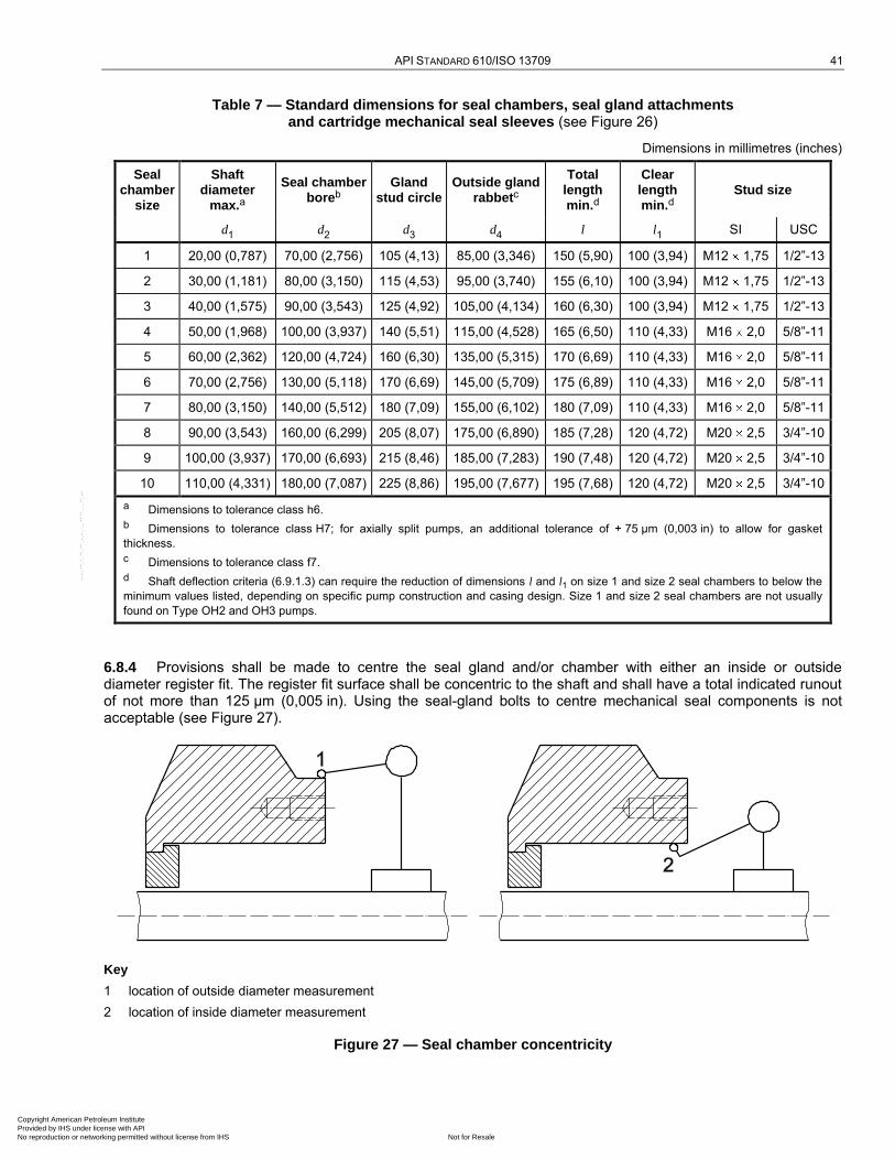
API STANDARD 610/ISO 13709 41
Table 7 — Standard dimensions for seal chambers, seal gland attachments and cartridge mechanical seal sleeves (see Figure 26)
Dimensions in millimetres (inches)
Seal chamber
size
Shaft diameter
max.a
Seal chamber boreb
Gland stud circle
Outside gland rabbetc
Total length min.d
Clear length min.d
Stud size
d1 d2 d3 d4 l l1 SI USC
1 20,00 (0,787) 70,00 (2,756) 105 (4,13) 85,00 (3,346) 150 (5,90) 100 (3,94) M12 1,75 1/2‖-13
2 30,00 (1,181) 80,00 (3,150) 115 (4,53) 95,00 (3,740) 155 (6,10) 100 (3,94) M12 1,75 1/2‖-13
3 40,00 (1,575) 90,00 (3,543) 125 (4,92) 105,00 (4,134) 160 (6,30) 100 (3,94) M12 1,75 1/2‖-13
4 50,00 (1,968) 100,00 (3,937) 140 (5,51) 115,00 (4,528) 165 (6,50) 110 (4,33) M16 2,0 5/8‖-11
5 60,00 (2,362) 120,00 (4,724) 160 (6,30) 135,00 (5,315) 170 (6,69) 110 (4,33) M16 2,0 5/8‖-11
6 70,00 (2,756) 130,00 (5,118) 170 (6,69) 145,00 (5,709) 175 (6,89) 110 (4,33) M16 2,0 5/8‖-11
7 80,00 (3,150) 140,00 (5,512) 180 (7,09) 155,00 (6,102) 180 (7,09) 110 (4,33) M16 2,0 5/8‖-11
8 90,00 (3,543) 160,00 (6,299) 205 (8,07) 175,00 (6,890) 185 (7,28) 120 (4,72) M20 2,5 3/4‖-10
9 100,00 (3,937) 170,00 (6,693) 215 (8,46) 185,00 (7,283) 190 (7,48) 120 (4,72) M20 2,5 3/4‖-10
10 110,00 (4,331) 180,00 (7,087) 225 (8,86) 195,00 (7,677) 195 (7,68) 120 (4,72) M20 2,5 3/4‖-10
a Dimensions to tolerance class h6.
b Dimensions to tolerance class H7; for axially split pumps, an additional tolerance of 75 µm (0,003 in) to allow for gasket
thickness.
c Dimensions to tolerance class f7.
d Shaft deflection criteria (6.9.1.3) can require the reduction of dimensions l and l1 on size 1 and size 2 seal chambers to below the
minimum values listed, depending on specific pump construction and casing design. Size 1 and size 2 seal chambers are not usually
found on Type OH2 and OH3 pumps.
6.8.4 Provisions shall be made to centre the seal gland and/or chamber with either an inside or outside diameter register fit. The register fit surface shall be concentric to the shaft and shall have a total indicated runout of not more than 125 µm (0,005 in). Using the seal-gland bolts to centre mechanical seal components is not acceptable (see Figure 27).
Key
1 location of outside diameter measurement
2 location of inside diameter measurement
Figure 27 — Seal chamber concentricity
Copyright American Petroleum Institute Provided by IHS under license with API
Not for ResaleNo reproduction or networking permitted without license from IHS
--`,,```,,,,````-`-`,,`,,`,`,,`---

42 CENTRIFUGAL PUMPS FOR PETROLEUM, PETROCHEMICAL AND NATURAL GAS INDUSTRIES
6.8.5 Seal chamber face runout (TIR) shall not exceed 0,5 µm/mm (0,000 5 in/in) of seal chamber bore (see Figure 28).
Key
1 location of face runout measurement
Figure 28 — Seal chamber face runout
6.8.6 The mating joint between the seal gland and the seal chamber face shall incorporate a confined gasket to prevent blowout. The gasket shall be of the controlled-compression type, for example an O-ring or a spiral-wound gasket, with a metal-to-metal joint contact. If space or design limitations make this requirement impractical, an alternative seal gland design shall be submitted to the purchaser for approval.
6.8.7 Specified seal and pump connections shall be identified by symbols permanently marked into the component (such as stamped, cast or chemically etched). Symbols shall be in accordance with those specified in ISO 21049.
6.8.8 Seal glands and seal chambers shall have provision for only those connections required by the seal flush plan. If additional tapped connection points are specified and are not used, they shall be plugged in accordance with 6.4.3.11.
6.8.9 Seal chambers shall be designed with space available to provide for an additional flush port to approximately the centre of the chamber and extending vertically upward. If specified, this port shall be drilled and machined for a piping connection. Tapered pipe thread connections are not allowed.
6.8.10 Provision shall be made to ensure complete venting of the seal chamber.
6.8.11 If specified, jackets shall be provided on seal chambers for heating. Heating requirements shall be agreed upon by the purchaser, vendor, and seal manufacturer for high-melting-point products.
6.8.12 Mechanical seals and glands for all pumps, except vertically suspended pumps shipped without drivers mounted, shall be installed in the pump before shipment and shall be clean and ready for initial service. If seals require final adjustment or installation in the field, the vendor shall attach a metal tag warning of this requirement.
6.8.13 The vendor and purchaser shall agree on the maximum static and dynamic sealing pressures that can be anticipated to occur in the seal chamber and the vendor shall state these values on the data sheet [see 3.23 and 3.25].
6.9 Dynamics
6.9.1 General
6.9.1.1 The topics of critical speed and lateral analysis are covered under each specific pump type in Clause 9.
Copyright American Petroleum Institute Provided by IHS under license with API
Not for ResaleNo reproduction or networking permitted without license from IHS
--`,,```,,,,````-`-`,,`,,`,`,,`---
API STANDARD 610/ISO 13709 43
6.9.1.2 The rotor of one- and two-stage pumps shall be designed so its first dry-bending critical speed is at least 20 % above the pump's maximum continuous operating speed.
6.9.1.3 To obtain satisfactory seal performance, the shaft stiffness shall limit the total deflection under the most severe dynamic conditions over the allowable operating range of the pump with maximum diameter impeller(s) and the specified speed and liquid to 50 µm (0,002 in) at the primary seal faces. This shaft-deflection limit may be achieved by a combination of shaft diameter, shaft span or overhang, and casing design (including the use of dual volutes or diffusers). For one- and two-stage pumps, no credit shall be taken for the liquid stiffening effects of impeller wear rings. For multistage pumps, liquid stiffening effects shall be considered and calculations shall be performed at both one and two times the nominal design clearances. The liquid stiffness of product-lubricated bearings and bearing bushings shall be calculated at both one and two times the nominal design clearances.
6.9.2 Torsional analysis
6.9.2.1 There are three general types of torsional analyses that are normally performed on pumps:
a) undamped natural frequency analysis: determination of the unit's torsional natural frequencies and associated mode shapes and generation of a Campbell diagram to determine potential resonance points;
b) steady-state damped response analysis: evaluation of the resonance points uncovered in the undamped analysis via a forced response analysis that utilizes representative values for excitation magnitudes and damping; the results are cyclic torques and stresses in all shaft elements in the model, which can then be used to evaluate the structural adequacy of the machine;
c) transient torsional analysis: similar to a steady-state damped response analysis, except that it is done for the transient condition and its results are cyclic torques and stresses as functions of time; by far, the most common application for this analysis type is the start-up of a synchronous motor.
A flow chart for the torsional analysis is shown in Figure 29.
Copyright American Petroleum Institute Provided by IHS under license with API
Not for ResaleNo reproduction or networking permitted without license from IHS
--`,,```,,,,````-`-`,,`,,`,`,,`---
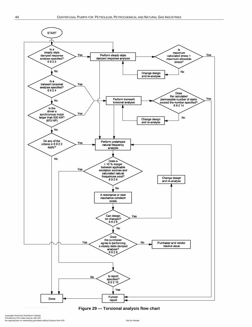
44 CENTRIFUGAL PUMPS FOR PETROLEUM, PETROCHEMICAL AND NATURAL GAS INDUSTRIES
Figure 29 — Torsional analysis flow chart
Copyright American Petroleum Institute Provided by IHS under license with API
Not for ResaleNo reproduction or networking permitted without license from IHS
--`,,```,,,,````-`-`,,`,,`,`,,`---
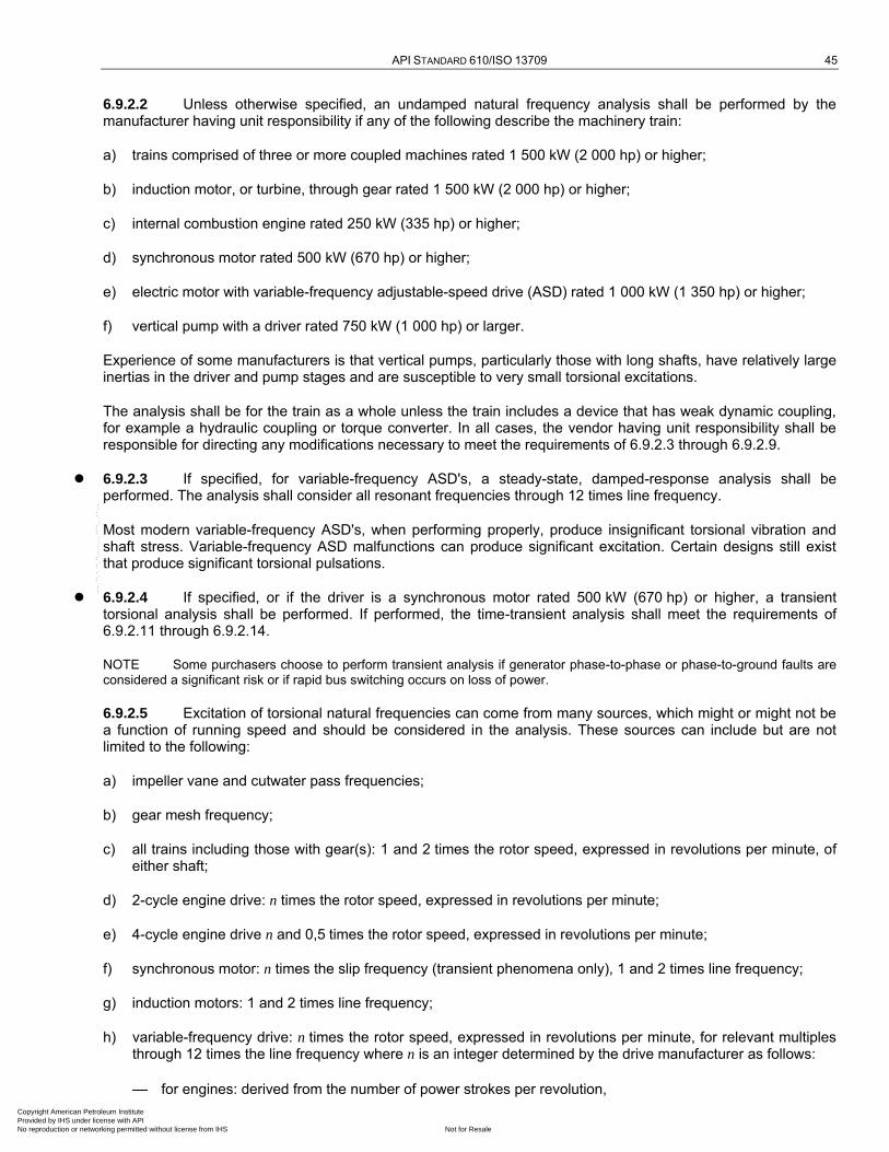
API STANDARD 610/ISO 13709 45
6.9.2.2 Unless otherwise specified, an undamped natural frequency analysis shall be performed by the manufacturer having unit responsibility if any of the following describe the machinery train:
a) trains comprised of three or more coupled machines rated 1 500 kW (2 000 hp) or higher;
b) induction motor, or turbine, through gear rated 1 500 kW (2 000 hp) or higher;
c) internal combustion engine rated 250 kW (335 hp) or higher;
d) synchronous motor rated 500 kW (670 hp) or higher;
e) electric motor with variable-frequency adjustable-speed drive (ASD) rated 1 000 kW (1 350 hp) or higher;
f) vertical pump with a driver rated 750 kW (1 000 hp) or larger.
Experience of some manufacturers is that vertical pumps, particularly those with long shafts, have relatively large inertias in the driver and pump stages and are susceptible to very small torsional excitations.
The analysis shall be for the train as a whole unless the train includes a device that has weak dynamic coupling, for example a hydraulic coupling or torque converter. In all cases, the vendor having unit responsibility shall be responsible for directing any modifications necessary to meet the requirements of 6.9.2.3 through 6.9.2.9.
6.9.2.3 If specified, for variable-frequency ASD's, a steady-state, damped-response analysis shall be performed. The analysis shall consider all resonant frequencies through 12 times line frequency.
Most modern variable-frequency ASD's, when performing properly, produce insignificant torsional vibration and shaft stress. Variable-frequency ASD malfunctions can produce significant excitation. Certain designs still exist that produce significant torsional pulsations.
6.9.2.4 If specified, or if the driver is a synchronous motor rated 500 kW (670 hp) or higher, a transient torsional analysis shall be performed. If performed, the time-transient analysis shall meet the requirements of 6.9.2.11 through 6.9.2.14.
NOTE Some purchasers choose to perform transient analysis if generator phase-to-phase or phase-to-ground faults are considered a significant risk or if rapid bus switching occurs on loss of power.
6.9.2.5 Excitation of torsional natural frequencies can come from many sources, which might or might not be a function of running speed and should be considered in the analysis. These sources can include but are not limited to the following:
a) impeller vane and cutwater pass frequencies;
b) gear mesh frequency;
c) all trains including those with gear(s): 1 and 2 times the rotor speed, expressed in revolutions per minute, of either shaft;
d) 2-cycle engine drive: n times the rotor speed, expressed in revolutions per minute;
e) 4-cycle engine drive n and 0,5 times the rotor speed, expressed in revolutions per minute;
f) synchronous motor: n times the slip frequency (transient phenomena only), 1 and 2 times line frequency;
g) induction motors: 1 and 2 times line frequency;
h) variable-frequency drive: n times the rotor speed, expressed in revolutions per minute, for relevant multiples through 12 times the line frequency where n is an integer determined by the drive manufacturer as follows:
for engines: derived from the number of power strokes per revolution,
Copyright American Petroleum Institute Provided by IHS under license with API
Not for ResaleNo reproduction or networking permitted without license from IHS
--`,,```,,,,````-`-`,,`,,`,`,,`---
46 CENTRIFUGAL PUMPS FOR PETROLEUM, PETROCHEMICAL AND NATURAL GAS INDUSTRIES
for motors: derived from the number of poles.
6.9.2.6 The torsional natural frequencies of the complete train shall be at least 10 % above or 10 % below any possible excitation frequency within the specified range of operating speeds (from minimum to maximum continuous speed).
6.9.2.7 Torsional natural frequencies at two or more times running speeds shall preferably be avoided in systems in which corresponding excitation frequencies occur. If the natural frequency cannot be moved, it shall be shown to have no adverse effect.
6.9.2.8 If torsional resonances are calculated to fall within the margin specified in 6.9.2.6 (and the purchaser and the vendor have agreed that all efforts to remove the resonance from within the limiting frequency range have been exhausted), a steady-state, damped-response analysis shall be performed to demonstrate that the resonances have no adverse effect on the complete train. The assumptions made in this analysis regarding the magnitude of excitation and the degree of damping shall be clearly stated. The acceptance criteria for this analysis shall be agreed upon by the purchaser and the vendor.
NOTE Typically, steady-state, damped torsional analyses of pumps driven by pulse-width-modulated variable-frequency drives have shown acceptably low stresses at the resonant conditions; these have no adverse effects on the machinery train.
6.9.2.9 Unless otherwise specified, if only a steady-state, undamped torsional analysis is performed, a Campbell diagram with a tabulation of the mass elastic data and brief explanation of the calculation method may be furnished to the purchaser in lieu of a report.
6.9.2.10 If specified, or if either a steady-state, damped-response analysis or a transient torsional analysis is performed, the manufacturer shall furnish a detailed report of the torsional analysis. The report shall include the following:
a) description of the method(s) used to calculate the natural frequencies;
b) diagram of the mass elastic system;
c) table of the mass moment and torsional stiffness of each element of the mass elastic system;
d) Campbell diagram;
e) mode-shape diagram with peak stresses shown for each resonant frequency, if a stress analysis is performed.
6.9.2.11 In addition to the parameters used to perform the steady-state, undamped torsional analysis specified in 6.9.2.2, the following shall be included in the transient torsional analysis:
a) motor average torque, as well as pulsating torque (direct and quadrature axis) vs. speed characteristics;
b) load torque vs. speed characteristics.
c) electrical-system characteristics affecting the motor terminal voltage or the assumptions made concerning the terminal voltage, including the method of starting, such as across the line, or some method of reduced voltage starting.
6.9.2.12 The analysis shall generate the maximum torque as well as a torque vs. time history for each of the shafts in the train.
The maximum torques shall be used to evaluate the peak torque capability of coupling components, gearing and interference fits of components, such as coupling hubs. The torque vs. time history shall be used to develop a cumulative damage-fatigue analysis of shafting, keys and coupling components.
6.9.2.13 Appropriate fatigue properties and stress concentrations shall be used.
Copyright American Petroleum Institute Provided by IHS under license with API
Not for ResaleNo reproduction or networking permitted without license from IHS
--`,,```,,,,````-`-`,,`,,`,`,,`---

API STANDARD 610/ISO 13709 47
6.9.2.14 An appropriate cumulative fatigue algorithm shall be used to develop a value for the safe number of starts. The purchaser and vendor shall mutually agree as to the safe number of starts.
NOTE Values used depend on the analytical model used and the vendor's experience. Values of 1 000 to 1 500 starts are common. ANSI/API Std 541 requires 5 000 starts. This is a reasonable assumption for a motor since it does not add significant cost to the design. The driven equipment, however, would be over-designed to meet this requirement.
EXAMPLE A 20-year life with 1 start per week equals 1 040 starts. Equipment of this type normally starts once every few years rather than once per week. It is necessary, therefore, to specify a reasonable number of starts.
6.9.3 Vibration
6.9.3.1 Centrifugal pump vibration varies with flow, usually being a minimum in the vicinity of best efficiency point flowrate and increasing as flow is increased or decreased. The change in vibration as flow is varied from best efficiency point flowrate depends upon the pump's energy density, its specific speed and its suction-specific speed. In general, the change in vibration increases with increasing energy density, higher specific speed and higher suction-specific speed.
With these general characteristics, a centrifugal pump's operating flow range can be divided into two regions, one termed the best efficiency or preferred operating region, over which the pump exhibits low vibration, the other termed the allowable operating region, with the limits, both high and low, defined as those flowrates at which the pump's vibration reaches a higher but still ―acceptable‖ level. Figure 30 illustrates the concept. Factors other than vibration, for example, temperature rise with decreasing flow or NPSH3 with increasing flow, can dictate a narrower allowable operating region. See also 6.1.12.
The allowable operating region shall be stated in the proposal. If the allowable operating region is limited by a factor other than vibration, that factor shall also be stated in the proposal.
6.9.3.2 During the performance test, overall vibration measurements over a range of 5 Hz to 1 000 Hz and a Fast Fourier Transform (FFT) spectrum shall be made at each test point except shutoff. The vibration measurements shall be made at the following locations:
a) on the bearing housing(s) or equivalent location(s) of all pumps, at the positions shown on Figures 31 through 33;
b) on the shaft of pumps with hydrodynamic bearings with proximity probes, if the pump has provisions for proximity probes.
6.9.3.3 The FFT spectra shall include the range of frequencies from 5 Hz to 2Z times running speed (where Z is the number of impeller vanes; in multistage pumps with different impellers, Z is the highest number of impeller vanes in any stage). If specified the plotted spectra shall be included with the pump test results.
NOTE The discrete frequencies 1,0, 2,0, and Z times running speed are associated with various pump phenomena, and
are, therefore, of particular interest in the spectra.
Copyright American Petroleum Institute Provided by IHS under license with API
Not for ResaleNo reproduction or networking permitted without license from IHS
--`,,```,,,,````-`-`,,`,,`,`,,`---
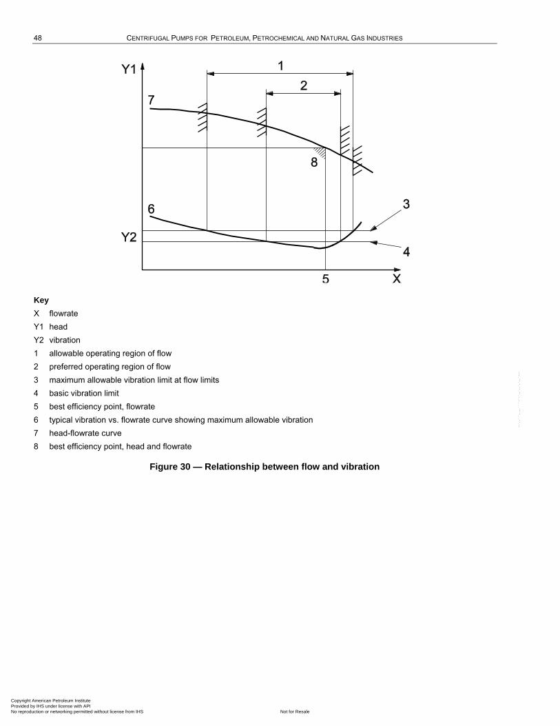
48 CENTRIFUGAL PUMPS FOR PETROLEUM, PETROCHEMICAL AND NATURAL GAS INDUSTRIES
Key
X flowrate
Y1 head
Y2 vibration
1 allowable operating region of flow
2 preferred operating region of flow
3 maximum allowable vibration limit at flow limits
4 basic vibration limit
5 best efficiency point, flowrate
6 typical vibration vs. flowrate curve showing maximum allowable vibration
7 head-flowrate curve
8 best efficiency point, head and flowrate
Figure 30 — Relationship between flow and vibration
Copyright American Petroleum Institute Provided by IHS under license with API
Not for ResaleNo reproduction or networking permitted without license from IHS
--`,,```,,,,````-`-`,,`,,`,`,,`---

API STANDARD 610/ISO 13709 49
Dimensions in millimetres (inches), unless otherwise specified
Key
1 dimple (see 6.10.2.9)
2 optional arrangement for mounting vibration-measuring equipment (see 6.10.2.10)
A axial
H horizontal
V vertical
Figure 31 — Locations for taking vibration readings on OH and BB type pumps
Copyright American Petroleum Institute Provided by IHS under license with API
Not for ResaleNo reproduction or networking permitted without license from IHS
--`,,```,,,,````-`-`,,`,,`,`,,`---
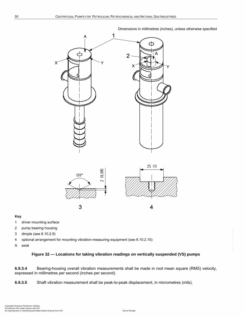
50 CENTRIFUGAL PUMPS FOR PETROLEUM, PETROCHEMICAL AND NATURAL GAS INDUSTRIES
Dimensions in millimetres (inches), unless otherwise specified
Key
1 driver mounting surface
2 pump bearing housing
3 dimple (see 6.10.2.9)
4 optional arrangement for mounting vibration-measuring equipment (see 6.10.2.10)
A axial
Figure 32 — Locations for taking vibration readings on vertically suspended (VS) pumps
6.9.3.4 Bearing-housing overall vibration measurements shall be made in root mean square (RMS) velocity, expressed in millimetres per second (inches per second).
6.9.3.5 Shaft vibration measurement shall be peak-to-peak displacement, in micrometres (mils).
Copyright American Petroleum Institute Provided by IHS under license with API
Not for ResaleNo reproduction or networking permitted without license from IHS
--`,,```,,,,````-`-`,,`,,`,`,,`---

API STANDARD 610/ISO 13709 51
Dimensions in millimetres (inches), unless otherwise specified
a) Vertical in-line (OH3) pump b) High-speed integrally geared (OH6) pump
c) Dimples (see 6.10.2.9)
d) Arrangement for mounting vibration-measuring equipment
(see 6.10.2.10)
Key
1 driver mounting surface
2 pump bearing housing
3 gearbox housing
4 suction flange
5 discharge flange
6 threaded connection for stud-mounting vibration sensor
A axial
Figure 33 — Locations for taking vibration readings on [a)] vertical in-line (OH3) and [b)] high-speed integrally geared (OH6) pumps
6.9.3.6 The vibration measured during the performance test shall not exceed the values shown in the following:
Table 8 for overhung and between-bearing pumps;
Table 9 for vertically suspended pumps;
Figure 34 for high energy pumps.
Pumps furnished with proximity probes shall meet both bearing-housing and shaft-vibration limits.
Copyright American Petroleum Institute Provided by IHS under license with API
Not for ResaleNo reproduction or networking permitted without license from IHS
--`,,```,,,,````-`-`,,`,,`,`,,`---
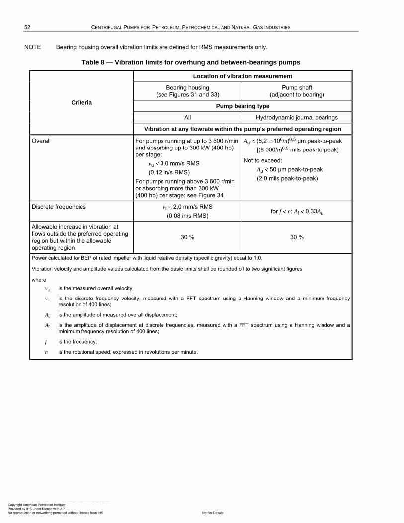
52 CENTRIFUGAL PUMPS FOR PETROLEUM, PETROCHEMICAL AND NATURAL GAS INDUSTRIES
NOTE Bearing housing overall vibration limits are defined for RMS measurements only.
Table 8 — Vibration limits for overhung and between-bearings pumps
Criteria
Location of vibration measurement
Bearing housing (see Figures 31 and 33)
Pump shaft (adjacent to bearing)
Pump bearing type
All Hydrodynamic journal bearings
Vibration at any flowrate within the pump's preferred operating region
Overall For pumps running at up to 3 600 r/min and absorbing up to 300 kW (400 hp) per stage:
vu 3,0 mm/s RMS
(0,12 in/s RMS)
For pumps running above 3 600 r/min or absorbing more than 300 kW (400 hp) per stage: see Figure 34
Au (5,2 106/n)0,5 µm peak-to-peak
[(8 000/n)0,5 mils peak-to-peak]
Not to exceed:
Au 50 µm peak-to-peak
(2,0 mils peak-to-peak)
Discrete frequencies vf 2,0 mm/s RMS
(0,08 in/s RMS) for f n: Af 0,33Au
Allowable increase in vibration at flows outside the preferred operating region but within the allowable operating region
30 % 30 %
Power calculated for BEP of rated impeller with liquid relative density (specific gravity) equal to 1,0.
Vibration velocity and amplitude values calculated from the basic limits shall be rounded off to two significant figures
where
vu is the measured overall velocity;
vf is the discrete frequency velocity, measured with a FFT spectrum using a Hanning window and a minimum frequency
resolution of 400 lines;
Au is the amplitude of measured overall displacement;
Af is the amplitude of displacement at discrete frequencies, measured with a FFT spectrum using a Hanning window and a
minimum frequency resolution of 400 lines;
f is the frequency;
n is the rotational speed, expressed in revolutions per minute.
Copyright American Petroleum Institute Provided by IHS under license with API
Not for ResaleNo reproduction or networking permitted without license from IHS
--`,,```,,,,````-`-`,,`,,`,`,,`---
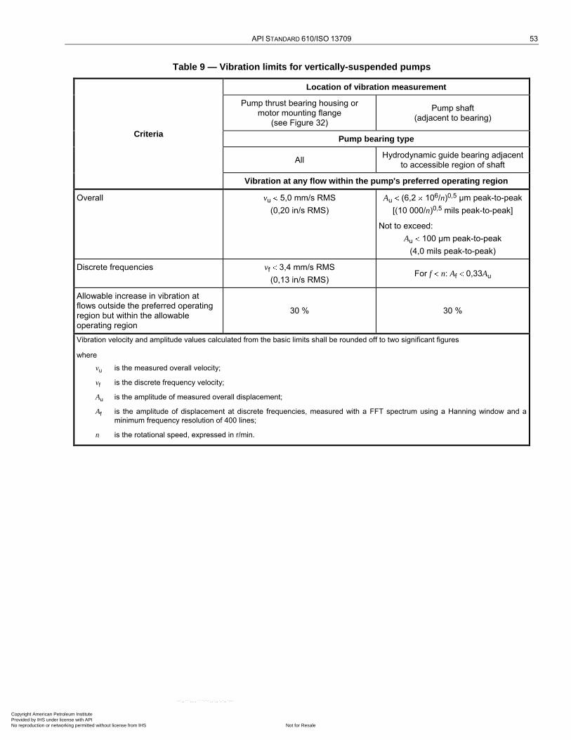
API STANDARD 610/ISO 13709 53
Table 9 — Vibration limits for vertically-suspended pumps
Criteria
Location of vibration measurement
Pump thrust bearing housing or motor mounting flange
(see Figure 32)
Pump shaft (adjacent to bearing)
Pump bearing type
All Hydrodynamic guide bearing adjacent
to accessible region of shaft
Vibration at any flow within the pump's preferred operating region
Overall vu 5,0 mm/s RMS
(0,20 in/s RMS)
Au (6,2 106/n)0,5 µm peak-to-peak
[(10 000/n)0,5 mils peak-to-peak]
Not to exceed:
Au 100 µm peak-to-peak
(4,0 mils peak-to-peak)
Discrete frequencies vf 3,4 mm/s RMS
(0,13 in/s RMS) For f n: Af 0,33Au
Allowable increase in vibration at flows outside the preferred operating region but within the allowable operating region
30 % 30 %
Vibration velocity and amplitude values calculated from the basic limits shall be rounded off to two significant figures
where
vu is the measured overall velocity;
vf is the discrete frequency velocity;
Au is the amplitude of measured overall displacement;
Af is the amplitude of displacement at discrete frequencies, measured with a FFT spectrum using a Hanning window and a
minimum frequency resolution of 400 lines;
n is the rotational speed, expressed in r/min.
Copyright American Petroleum Institute Provided by IHS under license with API
Not for ResaleNo reproduction or networking permitted without license from IHS
--`,,```,,,,````-`-`,,`,,`,`,,`---
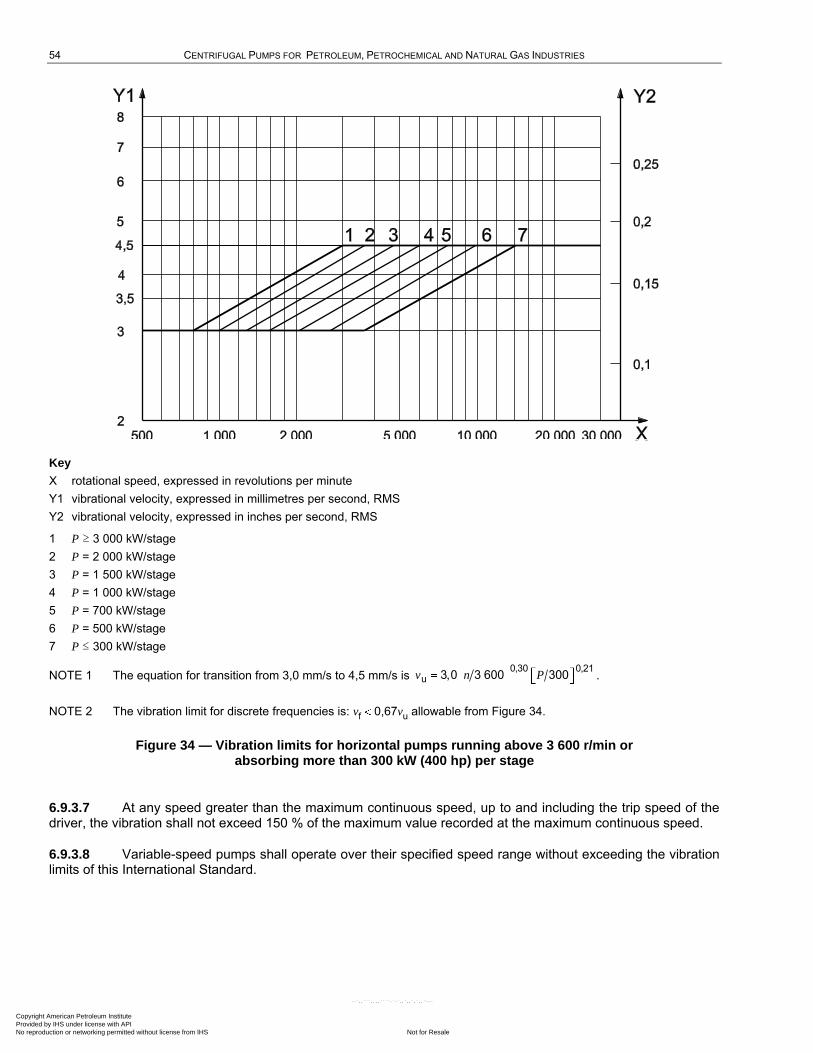
54 CENTRIFUGAL PUMPS FOR PETROLEUM, PETROCHEMICAL AND NATURAL GAS INDUSTRIES
Key
X rotational speed, expressed in revolutions per minute
Y1 vibrational velocity, expressed in millimetres per second, RMS
Y2 vibrational velocity, expressed in inches per second, RMS
1 P ≥ 3 000 kW/stage
2 P = 2 000 kW/stage
3 P = 1 500 kW/stage
4 P = 1 000 kW/stage
5 P = 700 kW/stage
6 P = 500 kW/stage
7 P ≤ 300 kW/stage
NOTE 1 The equation for transition from 3,0 mm/s to 4,5 mm/s is v n P0,30 0,21
u 3,0 3 600 300 .
NOTE 2 The vibration limit for discrete frequencies is: vf 0,67vu allowable from Figure 34.
Figure 34 — Vibration limits for horizontal pumps running above 3 600 r/min or absorbing more than 300 kW (400 hp) per stage
6.9.3.7 At any speed greater than the maximum continuous speed, up to and including the trip speed of the driver, the vibration shall not exceed 150 % of the maximum value recorded at the maximum continuous speed.
6.9.3.8 Variable-speed pumps shall operate over their specified speed range without exceeding the vibration limits of this International Standard.
Copyright American Petroleum Institute Provided by IHS under license with API
Not for ResaleNo reproduction or networking permitted without license from IHS
--`,,```,,,,````-`-`,,`,,`,`,,`---
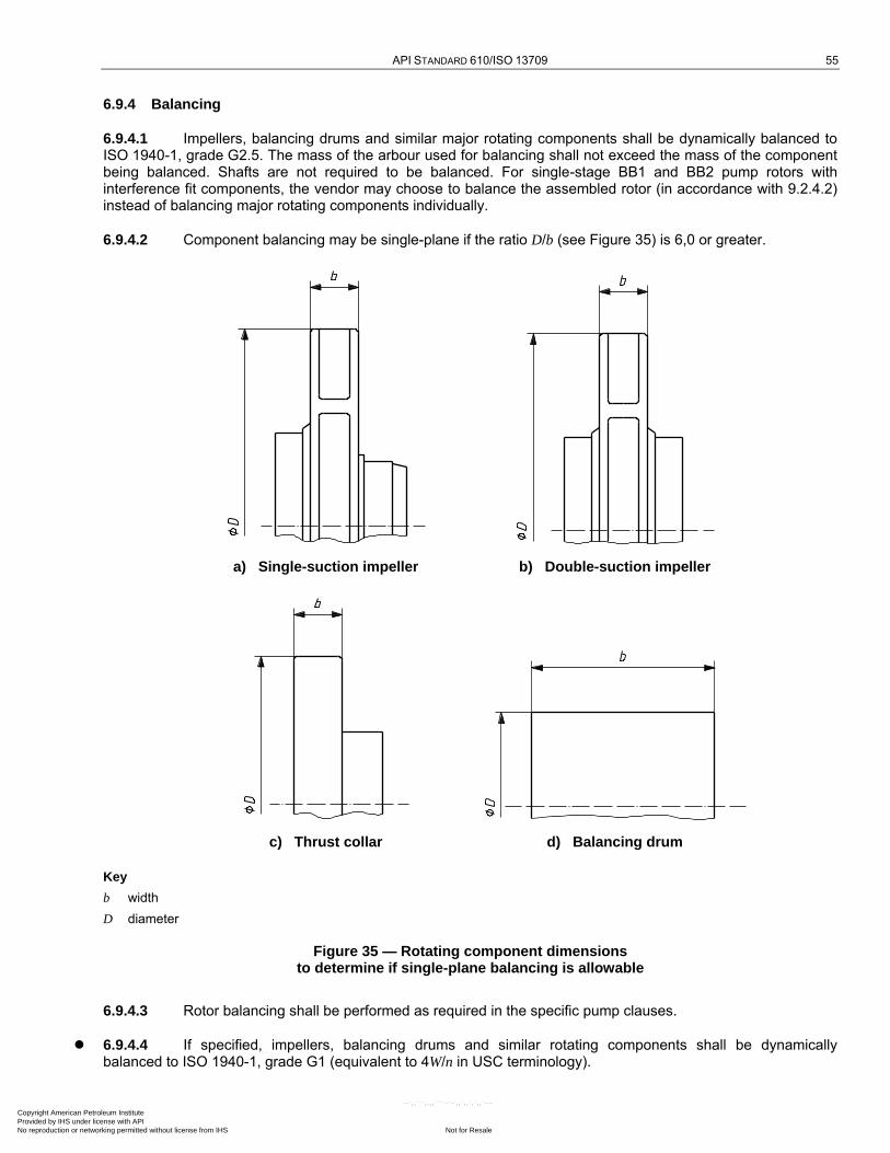
API STANDARD 610/ISO 13709 55
6.9.4 Balancing
6.9.4.1 Impellers, balancing drums and similar major rotating components shall be dynamically balanced to ISO 1940-1, grade G2.5. The mass of the arbour used for balancing shall not exceed the mass of the component being balanced. Shafts are not required to be balanced. For single-stage BB1 and BB2 pump rotors with interference fit components, the vendor may choose to balance the assembled rotor (in accordance with 9.2.4.2) instead of balancing major rotating components individually.
6.9.4.2 Component balancing may be single-plane if the ratio D/b (see Figure 35) is 6,0 or greater.
a) Single-suction impeller b) Double-suction impeller
c) Thrust collar d) Balancing drum
Key
b width
D diameter
Figure 35 — Rotating component dimensions to determine if single-plane balancing is allowable
6.9.4.3 Rotor balancing shall be performed as required in the specific pump clauses.
6.9.4.4 If specified, impellers, balancing drums and similar rotating components shall be dynamically balanced to ISO 1940-1, grade G1 (equivalent to 4W/n in USC terminology).
Copyright American Petroleum Institute Provided by IHS under license with API
Not for ResaleNo reproduction or networking permitted without license from IHS
--`,,```,,,,````-`-`,,`,,`,`,,`---
56 CENTRIFUGAL PUMPS FOR PETROLEUM, PETROCHEMICAL AND NATURAL GAS INDUSTRIES
In USC units, where the symbol W is used for mass, unbalance is expressed in Equation (2):
U KW n (2)
where
U is the unbalance per plane, expressed in ounce-inches;
K is a constant;
W is the component mass (for components), expressed in pounds; or the load per balancing machine journal (for rotors), expressed in pounds;
n is the rotational speed of the pump, expressed in revolutions per minute.
KW/n is a balance tolerance denominated solely in USC units. In International Standards, unbalance is expressed as a balance quality grade of ISO 1940-1. Each of the ISO balance quality grades covers a range of unbalance. The nominal equivalent USC unit limits given throughout this International Standard correspond approximately to the midpoint of the ISO range.
With modern balancing machines, it is feasible to balance components mounted on their arbours to U 4W/n (USC units) (nominally equivalent to ISO grade G1), or even lower depending upon the mass of the assembly, and to verify the unbalance of the assembly with a residual unbalance check. However, the mass eccentricity, e,
associated with unbalance less than U 8W/n (USC units) (nominally equivalent to ISO grade G2.5) is so small
[e.g. U 4W/n (USC units) gives e 0,000 070 in for an assembly intended to run at 3 600 r/min] that it cannot be maintained if the assembly is dismantled and remade. Balance grades below G2.5 (8W/n) (USC units) are, therefore, not repeatable for components.
6.10 Bearings and bearing housings
6.10.1 Bearings
6.10.1.1 Each shaft shall be supported by two radial bearings and one double-acting axial (thrust) bearing which might or might not be combined with one of the radial bearings. Bearings shall be one of the following arrangements:
rolling-element radial and thrust;
hydrodynamic radial and rolling-element thrust;
hydrodynamic radial and thrust.
Unless otherwise specified, the bearing type and arrangement shall be selected in accordance with the limitations in Table 10.
6.10.1.2 Thrust bearings shall be sized for continuous operation under all specified conditions, including maximum differential pressure and comply with the following.
a) All loads shall be determined at design internal clearances and also at twice design internal clearances.
b) Thrust forces for flexible metal-element couplings shall be calculated on the basis of the maximum allowable deflection permitted by the coupling manufacturer.
If a sleeve-bearing motor (without a thrust bearing) is directly connected to the pump shaft with a coupling, the coupling-transmitted thrust shall be assumed to be the maximum motor thrust.
c) In addition to thrust from the rotor and any internal gear reactions due to the most extreme allowable conditions, the axial force transmitted through flexible couplings shall be considered a part of the duty of any thrust bearing.
d) Thrust bearings shall provide full-load capabilities if the pump's normal direction of rotation is reversed.
Copyright American Petroleum Institute Provided by IHS under license with API
Not for ResaleNo reproduction or networking permitted without license from IHS
--`,,```,,,,````-`-`,,`,,`,`,,`---

API STANDARD 610/ISO 13709 57
6.10.1.3 Single-row, deep-groove ball bearings shall have a radial internal clearance in accordance with ISO 5753 Group 3 [larger than ―N‖ (Normal) internal clearance]. Single- or double-row bearings shall not have filling slots. Non-metallic cages shall not be used. Greater internal clearances can reduce the temperature rise of the lubricant. However, vibration velocities can be increased with greater clearances. The vendor shall ensure that the values for temperature rise (6.10.2.4) and vibration (6.9.3.6) meet the requirements of this International Standard.
NOTE For the purpose of this provision, ANSI/ABMA 20 Group 3 is equivalent to ISO 5753 Group 3.
6.10.1.4 Ball thrust bearings shall be of the paired, single-row, 40° (0,7 rad) angular contact type (7 000 series) with machined brass cages. Non-metallic cages shall not be used. Pressed steel cages may be used if approved by the purchaser. Unless otherwise specified, bearings shall be mounted in a paired arrangement installed back-to-back. The need for bearing clearance or preload shall be determined by the vendor to suit the application and meet the bearing life requirements of this International Standard.
NOTE There are applications where alternative bearing arrangements can be preferable, particularly where bearings operate continuously with minimal axial loads.
6.10.1.5 Rolling-element bearing life (basic rating life, L10h, for each bearing or bearing pair) shall be calculated in accordance with ISO 281 and be equivalent to at least 25 000 h with continuous operation at rated conditions, and at least 16 000 h at maximum radial and axial loads and rated speed.
NOTE 1 ISO 281 defines basic rating life, L10, in units of millions of revolutions. Industry practice is to convert this to hours and to refer to it as L10h.
NOTE 2 For the purpose of this provision, ANSI/ABMA 9 is equivalent to ISO 281.
6.10.1.6 Bearing system life (the calculated life of the combined system of bearings in the pump) shall be equivalent to at least 25 000 h with continuous operation at rated conditions, and at least 16 000 h at maximum radial and axial loads and rated speed. The system life shall be calculated as given in Equation (3):
2 33 2 3 2 3 2
10h,system 10hA 10hB 10h1 1 ... 1 NL L L L (3)
where
L10hA is the basic rating life, L10h, in accordance with ISO 281 for bearing A;
L10hB is the basic rating life, L10h, in accordance with ISO 281 for bearing B;
L10hN is the basic rating life, L10h, in accordance with ISO 281 for bearing N;
N is the number of bearings.
If specified, the bearing system life calculations shall be furnished. See Clause K.2 for a discussion of bearing system life.
NOTE A bearing system L10h life of 25 000 h and 16 000 h requires that the L10h life of each individual bearing be significantly higher.
6.10.1.7 If loads exceed the capability of paired, angular-contact bearings as described in 6.10.1.5, alternative rolling-element arrangements may be proposed.
6.10.1.8 Rolling-element bearings shall be located, retained and mounted in accordance with the following.
a) Bearings shall be retained on the shaft with an interference fit and fitted into the housing with a diametral clearance, both in accordance with ANSI/ABMA 7.
b) Bearings shall be mounted directly on the shaft. Bearing carriers are acceptable only with purchaser approval. Copyright American Petroleum Institute Provided by IHS under license with API
Not for ResaleNo reproduction or networking permitted without license from IHS
--`,,```,,,,````-`-`,,`,,`,`,,`---
58 CENTRIFUGAL PUMPS FOR PETROLEUM, PETROCHEMICAL AND NATURAL GAS INDUSTRIES
c) Bearings shall be located on the shaft using shoulders, collars or other positive locating devices. Snap rings and spring-type washers are not acceptable.
d) The device used to lock thrust bearings to shafts shall be restricted to a nut with a tongue-type lock washer.
NOTE This subclause applies to all rolling-element bearings, including both ball and roller types. For certain roller bearings, such as cylindrical roller types with separable races, bearing-housing diametral clearance might not be appropriate.
6.10.2 Bearing housings
6.10.2.1 Bearing housings shall be arranged so that bearings can be replaced without disturbing pump drives or mountings.
6.10.2.2 Bearing housings for oil-lubricated non-pressure-fed bearings shall be provided with threaded and plugged fill and drain openings of at least DN 15 (NPS 1/2). The housings shall be equipped with constant-level sight feed oilers at least 1,2 dl (4 fl oz) in volume, with a positive level positioner (not an external screw), heat-resistant glass containers and protective wire cages. Means shall be provided, such as a bulls-eye or an overfill plug, for detecting overfilling of the housings. A permanent indication of the proper oil level shall be accurately located and clearly marked on the outside of the bearing housing with permanent metal tags, marks inscribed in the castings, or other durable means. The sight glass (bulls-eye) shall be located such that the proper oil level elevation is at the midpoint (at 50 % up or down the viewing area).The purchaser shall specify if a particular model of oiler is required.
6.10.2.3 Bearing housings for pressure-lubricated hydrodynamic bearings shall be arranged to minimize foaming. The drain system shall be adequate to maintain the oil and foam level below shaft end seals.
6.10.2.4 Sufficient cooling, including an allowance for fouling, shall be provided to maintain oil and bearing temperatures as follows, based on the specified operating conditions and an ambient temperature of 43 °C (110 °F):
a) for pressurized systems, oil outlet temperature below 70 °C (160 °F) and bearing metal temperatures (if bearing-temperature sensors are supplied) less than 93 °C (200 °F); during shop testing, and under the most adverse specified operating conditions, the bearing-oil temperature rise shall not exceed 28 K (50 °R);
b) for ring-oiled or splash systems, an oil-sump temperature below 82 °C (180 °F); during shop testing, the sump oil temperature rise shall not exceed 40 K (70 °R) above the ambient temperature in the test cell measured at the time of each reading and (if bearing-temperature sensors are supplied) outer ring temperatures shall not exceed 93 °C (200 °F).
NOTE Pumps equipped with ring-oiled or splash lubrication systems normally do not reach temperature stabilization during performance tests of short duration and sometimes not even in 4 h tests. Temperature-stabilization testing is addressed in 8.3.4.2.1.
Copyright American Petroleum Institute Provided by IHS under license with API
Not for ResaleNo reproduction or networking permitted without license from IHS
--`,,```,,,,````-`-`,,`,,`,`,,`---
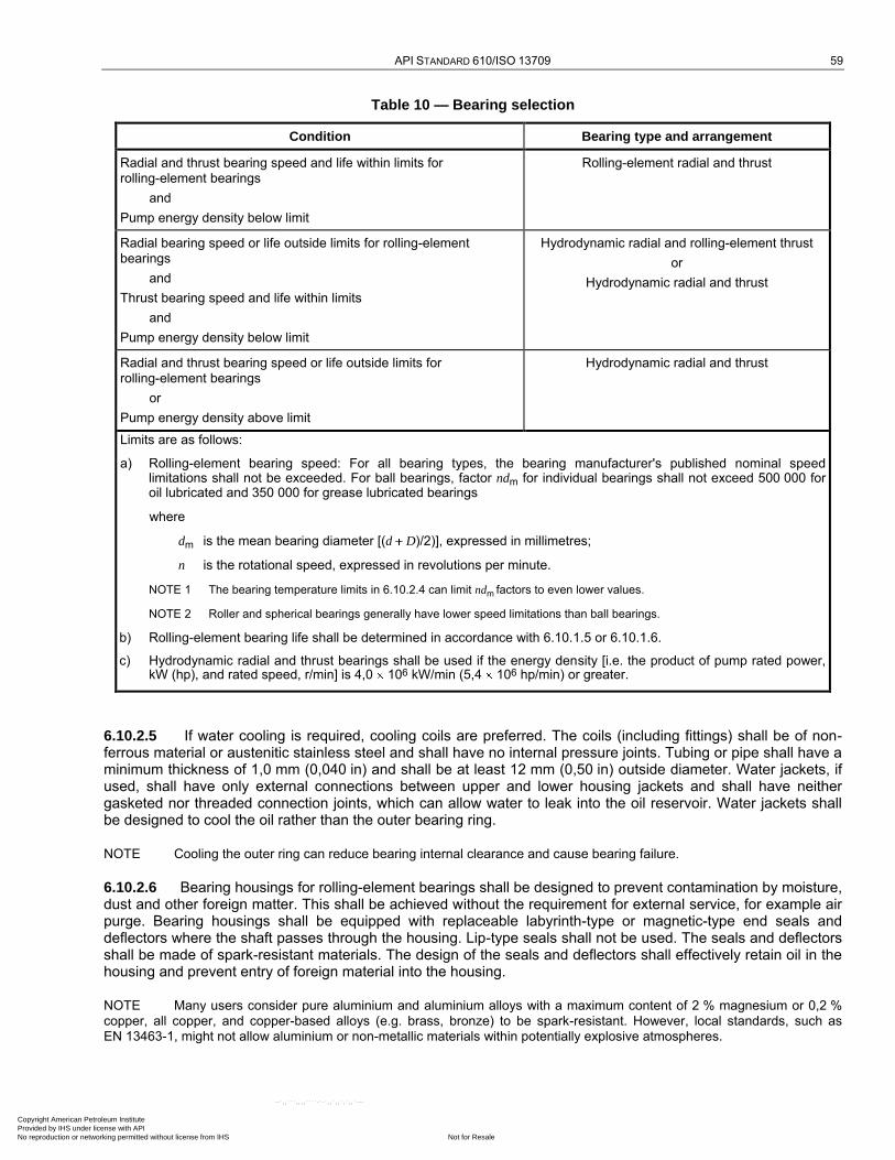
API STANDARD 610/ISO 13709 59
Table 10 — Bearing selection
Condition Bearing type and arrangement
Radial and thrust bearing speed and life within limits for rolling-element bearings
and
Pump energy density below limit
Rolling-element radial and thrust
Radial bearing speed or life outside limits for rolling-element bearings
and
Thrust bearing speed and life within limits
and
Pump energy density below limit
Hydrodynamic radial and rolling-element thrust
or
Hydrodynamic radial and thrust
Radial and thrust bearing speed or life outside limits for rolling-element bearings
or
Pump energy density above limit
Hydrodynamic radial and thrust
Limits are as follows:
a) Rolling-element bearing speed: For all bearing types, the bearing manufacturer's published nominal speed limitations shall not be exceeded. For ball bearings, factor ndm for individual bearings shall not exceed 500 000 for oil lubricated and 350 000 for grease lubricated bearings
where
dm is the mean bearing diameter [(d D)/2)], expressed in millimetres;
n is the rotational speed, expressed in revolutions per minute.
NOTE 1 The bearing temperature limits in 6.10.2.4 can limit ndm factors to even lower values.
NOTE 2 Roller and spherical bearings generally have lower speed limitations than ball bearings.
b) Rolling-element bearing life shall be determined in accordance with 6.10.1.5 or 6.10.1.6.
c) Hydrodynamic radial and thrust bearings shall be used if the energy density [i.e. the product of pump rated power, kW (hp), and rated speed, r/min] is 4,0 106 kW/min (5,4 106 hp/min) or greater.
6.10.2.5 If water cooling is required, cooling coils are preferred. The coils (including fittings) shall be of non-ferrous material or austenitic stainless steel and shall have no internal pressure joints. Tubing or pipe shall have a minimum thickness of 1,0 mm (0,040 in) and shall be at least 12 mm (0,50 in) outside diameter. Water jackets, if used, shall have only external connections between upper and lower housing jackets and shall have neither gasketed nor threaded connection joints, which can allow water to leak into the oil reservoir. Water jackets shall be designed to cool the oil rather than the outer bearing ring.
NOTE Cooling the outer ring can reduce bearing internal clearance and cause bearing failure.
6.10.2.6 Bearing housings for rolling-element bearings shall be designed to prevent contamination by moisture, dust and other foreign matter. This shall be achieved without the requirement for external service, for example air purge. Bearing housings shall be equipped with replaceable labyrinth-type or magnetic-type end seals and deflectors where the shaft passes through the housing. Lip-type seals shall not be used. The seals and deflectors shall be made of spark-resistant materials. The design of the seals and deflectors shall effectively retain oil in the housing and prevent entry of foreign material into the housing.
NOTE Many users consider pure aluminium and aluminium alloys with a maximum content of 2 % magnesium or 0,2 % copper, all copper, and copper-based alloys (e.g. brass, bronze) to be spark-resistant. However, local standards, such as EN 13463-1, might not allow aluminium or non-metallic materials within potentially explosive atmospheres.
Copyright American Petroleum Institute Provided by IHS under license with API
Not for ResaleNo reproduction or networking permitted without license from IHS
--`,,```,,,,````-`-`,,`,,`,`,,`---
60 CENTRIFUGAL PUMPS FOR PETROLEUM, PETROCHEMICAL AND NATURAL GAS INDUSTRIES
6.10.2.7 If oil-mist lubrication is specified, the requirements of 6.10.2.7.1 or 6.10.2.7.2 shall apply.
6.10.2.7.1 For pure oil-mist lubrication, bearings and bearing housings shall meet the following requirements.
a) A threaded 6 mm (NPS 1/4) oil-mist inlet connection shall be provided on the housing or end cover for each of the spaces between the rolling element bearing or bearing set and the bearing housing end seal.
b) Oil-mist fitting connections shall be located so that oil mist can flow through rolling element bearings.
NOTE Reclassifiers and oil-mist fittings are normally installed in the field.
c) Oil rings or flingers and constant-level oilers shall not be provided, and a mark indicating the oil level is not required.
d) Drain-back and any other (feed hole) oil passages in the bearing housing shall be plugged to prevent the oil mist from bypassing the bearings(s).
e) Water cooling systems shall not be provided.
NOTE At process operating temperatures above 300 °C (570 °F), bearing housings with pure oil-mist lubrication can require special features to reduce heating of the bearing races by heat transfer. Typical features are
heat sink type flingers;
stainless steel shafts having low thermal conductivity;
thermal barriers;
fan cooling;
purge oil-mist lubrication (in place of pure oil mist) with oil (sump) cooling.
6.10.2.7.2 For purge oil-mist lubrication, bearings and bearing housings shall meet the following requirements in a) to d) below.
a) A threaded 6 mm or 12 mm (NPS 1/4 or 1/2) oil-mist connection shall be located in the top half of the bearing housing to act also as a vent-and-fill connection.
b) Constant-level oilers shall be provided, and a mark indicating the oil level is required on the bearing housing. Bearing lubrication is by a conventional oil bath, flinger or oil ring system.
c) Constant-level sight feed oilers shall be equipped with overflow control to allow excess coalesced oil from the mist system to drain from the bearing housing so that oil level in the sump is maintained at proper level. The oil shall be contained to prevent it from draining onto the baseplate.
d) Constant-level sight feed oilers shall be piped so that they operate at the internal pressure of the bearing housing, do not vent excess mist at the bearing housing, or allow oil to drip to the baseplate.
6.10.2.7.3 For both pure and purge mist applications, a drain connection shall be located on the bottom of the bearing housing to provide complete oil drainage (see 6.10.2.7.5).
6.10.2.7.4 Shielded or sealed bearings shall not be used in conjunction with either pure or purge oil-mist systems.
6.10.2.7.5 The oil-mist supply, reclassifier(s) and drain fitting shall be provided by the purchaser. Unless otherwise specified, directional reclassifiers, if required, shall be provided by the machine manufacturer.
6.10.2.8 Housings for ring oil-lubricated bearings shall be provided with (plugged) ports positioned to allow visual inspection of the oil rings while the pump is running.
Copyright American Petroleum Institute Provided by IHS under license with API
Not for ResaleNo reproduction or networking permitted without license from IHS
--`,,```,,,,````-`-`,,`,,`,`,,`---
API STANDARD 610/ISO 13709 61
6.10.2.9 All bearing housings shall be dimpled at the locations shown on Figures 31 through 33 to facilitate consistent-vibration measurements. The dimples shall be suitable for accurate location of a hand-held vibration transducer with an extension ―wand‖. Dimples shall be either cast or machined and shall be nominally 2 mm (0,080 in) deep with an included angle of 120°.
6.10.2.10 If specified, bearing housings shall have a threaded connection(s) for permanently mounting vibration transducers in accordance with ANSI/API Std 670. If metric fasteners are supplied, the threads shall be M8 1,25. See Figures 31 through 33.
6.10.2.11 If specified, a flat surface at least 25 mm (1 in) in diameter shall be supplied for the location of magnetic-based vibration-measuring equipment.
6.10.2.12 The purchaser shall specify whether synthetic oil shall be used. If specified, the purchaser shall specify the oil type. The vendor shall ensure that bearing-housing internal paint, if used, is compatible with the specified oil.
6.11 Lubrication
6.11.1 Unless otherwise specified, bearings and bearing housings shall be designed for oil lubrication using a mineral (hydrocarbon) oil.
6.11.2 The operation and maintenance manual shall describe how the lubrication system circulates oil.
6.11.3 If specified, provisions shall be made for either pure oil or purge oil-mist lubrication (see 6.10.2.7 for requirements).
6.11.4 If specified, rolling-element bearings shall be grease-lubricated in accordance with the following.
a) Grease life (re-lubrication interval) shall be estimated using the method recommended by the bearing manufacturer or an alternative method approved by the purchaser.
b) Grease lubrication shall not be used if the estimated grease life is less than 2 000 h.
c) If the estimated grease life is 2 000 h or greater but less than 25 000 h, provision shall be made for re-greasing the bearings in service and for the effective discharge of old or excess grease, and the vendor shall advise the purchaser of the required re-greasing interval.
d) If the estimated grease life is 25 000 h or more, grease nipples or any other system for the addition of grease in service shall not be fitted.
6.12 Materials
6.12.1 General
6.12.1.1 The purchaser shall specify the material class for pump parts. Table G.1 provides a guide showing material classes that can be appropriate for various services. Alternative materials recommended for the service by the vendor, including material that can improve life and performance in service, may also be included in the proposal and listed on the final data sheets.
6.12.1.2 The material specification of all components listed in Table H.1 shall be clearly stated in the vendor's proposal. Materials shall be identified by reference to applicable International Standards, including the material grade (Tables H.2 and H.3 may be used for guidance). If International Standard materials are not available, internationally recognized national or other standards may be used. If no such designations are available, the vendor's material specification, giving physical properties, chemical composition and test requirements, shall be included in the proposal.
6.12.1.3 The material specification of all gaskets and O-rings exposed to the pumped liquid shall be identified in the proposal. O-rings shall be selected and their application limited in accordance with ISO 21049.
Copyright American Petroleum Institute Provided by IHS under license with API
Not for ResaleNo reproduction or networking permitted without license from IHS
--`,,```,,,,````-`-`,,`,,`,`,,`---

62 CENTRIFUGAL PUMPS FOR PETROLEUM, PETROCHEMICAL AND NATURAL GAS INDUSTRIES
6.12.1.4 Pump parts having strength or pressure-integrity requirements are designated as ―full compliance‖ materials in Table H.1 and shall meet all the requirements of the agreed specifications. For any other part (e.g. if corrosion resistance is the primary concern), it is necessary to comply only with the specified chemical composition. Auxiliary piping materials are covered in 7.5.
6.12.1.5 The vendor shall specify the optional tests and inspection procedures that are necessary to ensure that materials are satisfactory for the service. The purchaser shall specify if any additional tests and inspections are required, especially for materials used for components or in services considered critical by the purchaser. Purchaser-specified test and inspection requirements should be identified in the ―remarks‖ section of the data sheets (Annex N).
6.12.1.6 Pump materials shall be in accordance with Table H.1. Cast iron construction (Class I-1 or I-2 in Table H.1) may be offered only for services with a maximum allowable gauge working pressure not exceeding 1 725 kPa (17,25 bar; 250 psi) (see 6.3.5).
6.12.1.7 If austenitic stainless steel parts exposed to conditions that can promote intergranular corrosion are fabricated, hard-faced, overlaid or repaired by welding, they shall be made of low-carbon or stabilized grades.
NOTE Overlays or hard surfaces that contain more than 0,10 % carbon can sensitize both low-carbon and stabilized grades of austenitic stainless steel unless a buffer layer that is not sensitive to intergranular corrosion is applied.
6.12.1.8 If specified, the vendor shall furnish material certificates that include chemical analysis and mechanical properties for the heats from which the material is supplied for pressure-containing castings and forgings, impellers and shafts. Unless otherwise specified, piping nipples, auxiliary piping components, and bolting are excluded from this requirement.
6.12.1.9 The purchaser shall specify any erosive or corrosive agents (including trace quantities) present in the process liquids and in the site environment, including constituents that can cause stress-corrosion cracking or attack elastomers.
NOTE 1 Typical agents of concern are hydrogen sulfide, amines, chlorides, bromides, iodides, cyanides, fluorides, naphthenic acid and polythionic acid. Other agents affecting elastomer selection include ketones, ethylene oxide, sodium hydroxide, methanol, benzene and solvents.
NOTE 2 If chlorides are present in the pumped liquid in a concentration above 10 mg/kg (10 ppm), it is necessary to use caution when applying stainless steel.
6.12.1.10 If specified, coatings of a type agreed between the purchaser and the vendor shall be applied to impellers and other wetted parts to minimize erosion or to improve efficiency. If coatings are applied to rotating components, the acceptance balance shall be performed after coatings have been applied. The sequence of procedures for balancing and coating of rotating components shall be agreed between the purchaser and the vendor. The ―remarks‖ section of the data sheets (see Annex N) should be used for stating these coating requirements.
Rotating parts should be balanced before coating in order to minimize balance corrections to coated areas. By minimizing the area to be recoated, a final correction after coating repair might not be required.
6.12.1.11 If mating parts, such as studs and nuts of austenitic stainless steel or materials with similar galling tendencies, are used, they shall be lubricated with an anti-seizure compound compatible with the material(s) and specified process liquid(s).
NOTE The torque loading values required to achieve the necessary preload can vary considerably depending upon the thread lubricant.
6.12.1.12 The purchaser shall specify the amount of wet H2S that can be present, considering normal operation, start-up, shutdown, idle standby, upsets, or unusual operating conditions such as catalyst regeneration.
In many applications, small amounts of wet H2S are sufficient to require materials resistant to sulfide stress-corrosion cracking. If trace quantities of wet H2S are known to be present or if there is any uncertainty about the
Copyright American Petroleum Institute Provided by IHS under license with API
Not for ResaleNo reproduction or networking permitted without license from IHS
--`,,```,,,,````-`-`,,`,,`,`,,`---

API STANDARD 610/ISO 13709 63
amount of wet H2S that can be present, the purchaser should consider specifying that reduced-hardness materials are required.
6.12.1.12.1 The purchaser shall specify if reduced-hardness materials are required.
6.12.1.12.2 If reduced-hardness materials are specified in 6.12.1.12.1, they shall be supplied in accordance with NACE MR0103.
NOTE NACE MR0103 applied to oil refineries, LNG plants and chemical plants. NACE MR0103 applies to materials potentially subject to sulfide stress-corrosion cracking.
6.12.1.12.3 If specified, reduced-hardness materials shall be supplied in accordance with ISO 15156-1.
NOTE 1 For the purposes of this provision, ANSI/NACE MR0175 is equivalent to ISO 15156-1.
NOTE 2 ISO 15156 (all parts), which is the equivalent of ANSI/NACE MR0175, applies to material potentially subject to sulfide and chloride stress-corrosion cracking in oil and gas production facilities and natural gas sweetening plants.
6.12.1.12.4 If reduced-hardness materials are specified, ferrous material not covered by NACE MR0103 or ISO 15156-1 (ANSI/NACE MR0175) shall have a yield strength not exceeding 620 N/mm2 (90 000 psi) and a hardness not exceeding HRC 22. Components that are fabricated by welding shall be postweld heat-treated, if required, so that both the welds and heat-affected zones meet the yield strength and hardness requirements.
NOTE For the purposes of this provision, ANSI/NACE MR0175 is equivalent to ISO 15156-1.
6.12.1.12.5 If reduced hardness materials are specified, the following components, as a minimum, shall have reduced hardness:
a) pressure casing;
b) shafting (including wetted shaft nuts);
c) pressure-retaining mechanical seal components (excluding the seal ring and mating ring);
d) wetted bolting;
e) bowls.
Double-casing-pump inner-casing parts that are in compression, such as diffusers, are not considered pressure-casing parts.
6.12.1.12.6 Renewable impeller wear rings that it is necessary to through-harden above HRC 22 for proper pump operation shall not be used if reduced-hardness materials are specified. Impellers may be provided with either hard-coated or surface-hardened integral wear surfaces or renewable wear rings. If approved by the purchaser, in lieu of furnishing renewable wear rings, wear surfaces may be surface-hardened or hardened by the application of a suitable coating.
6.12.1.13 Low carbon steels can be notch-sensitive and be susceptible to brittle fracture, even at ambient (room) temperatures. Therefore, only fully killed, normalized steels made to fine-grain practice shall be used.
6.12.1.14 If dissimilar materials with significantly different electrochemical potentials are placed in contact in the presence of an electrolytic solution, galvanic couples can be created that can result in serious corrosion of the less noble material. The vendor shall select materials to avoid conditions that can result in galvanic corrosion. Where such conditions cannot be avoided, the purchaser and the vendor shall agree on the material selection and any other precautions necessary. See NACE Corrosion Engineer's Reference Book [89] for one source for selection of suitable materials in these situations.
Copyright American Petroleum Institute Provided by IHS under license with API
Not for ResaleNo reproduction or networking permitted without license from IHS
--`,,```,,,,````-`-`,,`,,`,`,,`---
64 CENTRIFUGAL PUMPS FOR PETROLEUM, PETROCHEMICAL AND NATURAL GAS INDUSTRIES
6.12.1.15 Bearing housings, load-carrying bearing housing covers and brackets between the pump casings or heads and the bearing housings shall be steel except for pumps constructed in accordance with Table H.1, Classes I-1 or I-2. Driver supports for vertical pumps that utilize thrust bearings in the driver to support the shaft shall be steel.
6.12.2 Castings
6.12.2.1 Surfaces of castings shall be cleaned by sandblasting, shot blasting, chemical cleaning or any other standard method to meet the visual requirements of MSS SP-55. Mould-parting fins and remains of gates and risers shall be chipped, filed or ground flush.
6.12.2.2 The use of chaplets in pressure castings shall be held to a minimum. The chaplets shall be clean and corrosion-free (plating is permitted), and of a composition compatible with the casting. Chaplets shall not be used in impeller castings.
6.12.2.3 Ferrous pressure boundary and impeller castings shall not be repaired by welding, peening, plugging, burning in or impregnating, except as allowed by the following.
a) Weldable grades of steel castings may be repaired by welding in accordance with 6.12.3. Weld repairs shall be inspected according to the same quality standard used to inspect the casting.
b) Iron castings may be repaired by plugging within the limits of the applicable material specification. The holes drilled for plugs shall be carefully examined, using liquid penetrant, to ensure that all defective material has been removed. All repairs that are not covered by material specifications shall be subject to the purchaser's approval.
6.12.2.4 Fully enclosed, cored voids that become fully enclosed by methods such as plugging, welding or assembly shall not be used.
6.12.2.5 If specified, for casting repairs made in the vendor's shop, repair procedures including weld maps shall be submitted for purchaser's approval. The purchaser shall specify if approval is required before proceeding with repair. Repairs made at the foundry level shall be controlled by the casting material specification (―producing specification‖).
6.12.2.6 Pressure-containing castings of carbon steel shall be furnished in the normalized and tempered or quenched and tempered condition.
6.12.3 Welding
6.12.3.1 Welding and weld repairs shall be performed by operators and in accordance with procedures qualified to the requirements of Table 11. Alternative standards may be proposed by the vendor for the purchaser's approval. The welding and material inspection data sheet in Annex N may be used for this purpose.
Table 11 — Welding requirements
Requirement Applicable code or standard
Welder/operator qualification ASME BPVC IX or ISO 9606 (all parts)
Welding procedure qualification Applicable material specification or, where weld procedures are not covered by the material specification, ISO 15609 (all parts), ASME BPVC IX or ANSI/ASME B31.3
Non-pressure-retaining structural welding, such as baseplates or supports
ISO 10721-2
Magnetic-particle or liquid-penetrant examination of
the plate edges
ASME BPVC VIII, Division 1, UG-93(d)(34)
Post-weld heat-treatment Applicable material specification, EN 13445-4, ASME BPVC VIII,
Division 1, UW 40, or ANSI/ASME B31.3
Post-weld heat-treatment of casing fabrication welds Applicable material specification, EN 13445-4, or ASME BPVC VIII, Division 1
Copyright American Petroleum Institute Provided by IHS under license with API
Not for ResaleNo reproduction or networking permitted without license from IHS
--`,,```,,,,````-`-`,,`,,`,`,,`---
API STANDARD 610/ISO 13709 65
NOTE For the purpose of this provision, ANSI/AWS D1.1/D1.1M is equivalent to ISO 10721-2.
6.12.3.2 The vendor shall be responsible for the review of all repairs and repair welds to ensure they are properly heat-treated and non-destructively examined for soundness and compliance with the applicable qualified procedures (see 6.12.3.1 and 8.2.2.1).
6.12.3.3 Pressure-containing casings made of wrought materials or combinations of wrought and cast materials shall conform to the conditions specified in a) through d) as follows. These requirements do not apply to casing nozzles and auxiliary connections; see 6.12.3.4.
a) Accessible surfaces of welds shall be inspected by magnetic-particle or liquid-penetrant examination after back chipping or gouging and again after post-weld heat-treatment or, for austenitic stainless steels, after solution annealing.
b) Pressure-containing welds, including welds of the casing to axial-joint and radial-joint flanges, shall be full-penetration welds.
c) If dimensional stability of such a casing component is required for the integrity of pump operation, then post-weld heat-treatment shall be performed regardless of thickness.
d) Plate edges shall be inspected by magnetic-particle or liquid-penetrant examination as required by internationally recognized standards, such as ASME BPVC, Section VIII, Division 1, UG-93 (d)(3).
6.12.3.4 Connections welded to pressure casings shall be installed as specified in a) through e) as follows.
a) Attachment of suction and discharge nozzles shall be by means of full-fusion, full-penetration welds using welding neck flanges. Dissimilar metal weldments shall not be used.
b) Auxiliary piping welded to alloy steel casings shall be of a material with the same nominal properties as the casing material or shall be of low-carbon austenitic stainless steel. Other materials compatible with the casing material and intended service may be used with the purchaser's approval.
c) Post-weld heat-treatment, if required, shall be carried out after all welds, including piping welds, have been completed.
d) If specified, proposed connection designs shall be submitted to the purchaser for approval before fabrication. The drawing shall show weld designs, size, materials, and pre-weld and post-weld heat-treatments.
e) Suction and discharge nozzle welds shall be inspected by magnetic-particle or liquid-penetrant examination after back chipping or gouging and again after post-weld heat-treatment or, for austenitic stainless steels, after solution annealing. The purchaser shall specify if the following additional examinations shall be performed:
1) magnetic-particle or liquid-penetrant examination of auxiliary connection welds;
2) ultrasonic or radiographic examination of any casing welds.
6.12.4 Low-temperature service
6.12.4.1 The purchaser shall specify the minimum design metal temperature to which the pump will be subjected in service. This temperature shall be used to establish impact test requirements. Normally, this is the lower of the minimum surrounding ambient temperature or minimum liquid pumping temperature. However, the purchaser may specify a minimum design metal temperature based on pump liquid properties, such as auto refrigeration at reduced pressures.
Copyright American Petroleum Institute Provided by IHS under license with API
Not for ResaleNo reproduction or networking permitted without license from IHS
--`,,```,,,,````-`-`,,`,,`,`,,`---
66 CENTRIFUGAL PUMPS FOR PETROLEUM, PETROCHEMICAL AND NATURAL GAS INDUSTRIES
6.12.4.2 To avoid brittle failures, materials of construction for low-temperature service shall be suitable for the minimum design metal temperature in accordance with the codes and other requirements specified. The purchaser and the vendor shall agree on any special precautions necessary, with regards to conditions that can occur during operation, maintenance, transportation, erection, commissioning and testing.
The suitability of a material for application at temperatures below the ductile-brittle transition temperature is affected by the selection of fabrication methods and welding procedures. The published design-allowable stresses for metallic materials in internationally recognized standards, such as the ASME BPVC and ANSI standards, are based on minimum tensile properties. Some standards do not differentiate between rimmed, semi-killed, fully killed hot-rolled and normalized material, nor do they take into account whether materials were produced under fine- or course-grain practices. The vendor should, therefore, exercise caution in the selection of materials, fabrication methods and welding procedures for parts intended for services below 40 °C (100 °F).
6.12.4.3 The purchaser shall specify whether EN 13445 (all parts) or ASME BPVC, Section VIII, Division 1, shall apply with regard to impact-testing requirements.
6.12.4.4 The governing thickness used to determine impact-testing requirements shall be the greater of the following:
a) nominal thickness of the largest butt-welded joint;
b) largest nominal section for pressure containment, excluding:
1) structural support sections, such as feet or lugs,
2) sections with increased thickness required for rigidity to mitigate shaft deflection,
3) structural sections required for attachment or inclusion of mechanical features such as jackets or seal chambers;
c) one-fourth of the nominal flange thickness, including parting flange thickness for axially split casings (in recognition that the predominant flange stress is not a membrane stress).
6.12.4.5 If ASME BPVC, Section VIII, Division 1, is specified (see 6.12.4.3), the following shall apply.
a) All pressure-retaining steels applied at a specified minimum design metal temperature below °C ( 20 °F) shall have a Charpy V-notch impact test of the base metal and the weld joint unless they are exempt in accordance with ASME BPVC, Section VIII, Division 1, UHA-51.
b) Carbon steel and low-alloy steel pressure-retaining parts applied at a specified minimum design metal
temperature between 30 °C ( 20 °F) and 40 °C (100 °F) shall require impact testing as follows.
Impact testing is not required for parts with a governing thickness of 25 mm (1 in) or less.
Impact testing exemptions for parts with a governing thickness greater than 25 mm (1 in) shall be established in accordance with ASME BPVC, Section VIII, Division 1, UCS-66. Minimum design metal temperature without impact testing may be reduced as shown in Figure UCS-66.1. If the material is not exempt, Charpy V-notch impact test results shall meet the minimum impact energy requirements of ASME BPVC, Section VIII, Division 1, UG-84.
6.13 Nameplates and rotation arrows
6.13.1 A nameplate shall be securely attached at a readily visible location on the equipment and on any other major piece of auxiliary equipment.
Copyright American Petroleum Institute Provided by IHS under license with API
Not for ResaleNo reproduction or networking permitted without license from IHS
--`,,```,,,,````-`-`,,`,,`,`,,`---

API STANDARD 610/ISO 13709 67
6.13.2 The nameplate shall be stamped with the following information, in units consistent with the data sheet:
a) purchaser's item number;
b) vendor's size and model number;
c) pump serial number;
d) rated flow;
e) rated head;
f) casing hydrostatic test pressure;
g) speed;
h) manufacturer's bearing identification numbers (if applicable);
i) maximum allowable working pressure (MAWP);
j) temperature basis for MAWP.
6.13.3 In addition to being stamped on the nameplate, the pump serial number shall be plainly and permanently marked on the pump casing.
6.13.4 Rotation arrows shall be cast in or attached to each major item of rotating equipment at a readily visible location.
6.13.5 Nameplates and rotation arrows (if attached) shall be of austenitic stainless steel or of nickel-copper alloy [equivalent to Monel15)]. Attachment pins shall be of the same material as the nameplate or rotation arrow. Welding is not permitted as an attachment method.
7 Accessories
7.1 Drivers
7.1.1 The driver shall be sized to meet the maximum specified operating conditions, including bearing, mechanical seal, external gear, and coupling losses, as applicable, and shall be in accordance with the applicable specifications, as stated in the inquiry specification, data sheets and order. The driver shall be suitable for satisfactory operation under the utility and site conditions specified.
7.1.2 The driver shall be sized to accommodate specified process variations such as changes in pressure, temperature, or properties of the liquid handled, as well as specified special plant start-up conditions.
7.1.3 Unless otherwise specified, for drive-train components that have a mass greater than 225 kg (500 lb), the equipment feet shall be provided with vertical jackscrews.
7.1.4 Motors shall have nameplate power ratings, excluding the service factor (if any), at least equal to the percentages of power at pump rated conditions given in Table 12. However, the power at rated conditions shall not exceed the motor nameplate rating. The smallest acceptable motor power rating to be supplied is 4 kW (5 hp). If it appears that this procedure leads to unnecessary oversizing of the motor, an alternative proposal shall be submitted for the purchaser's approval.
15) MonelTM is an example of a suitable product available commercially. This information is given for the convenience of users of this International Standard and does not constitute an endorsement by API/ISO of this product.
Copyright American Petroleum Institute Provided by IHS under license with API
Not for ResaleNo reproduction or networking permitted without license from IHS
--`,,```,,,,````-`-`,,`,,`,`,,`---
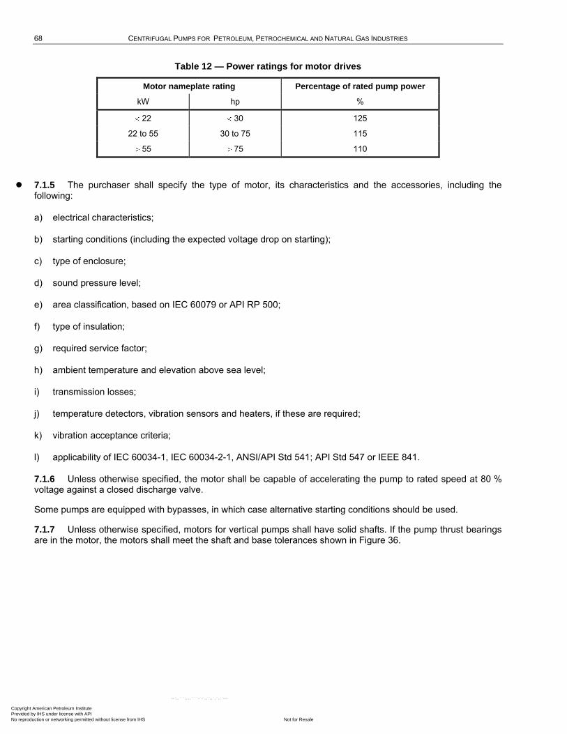
68 CENTRIFUGAL PUMPS FOR PETROLEUM, PETROCHEMICAL AND NATURAL GAS INDUSTRIES
Table 12 — Power ratings for motor drives
Motor nameplate rating Percentage of rated pump power
kW hp %
22 30 125
22 to 55 30 to 75 115
55 75 110
7.1.5 The purchaser shall specify the type of motor, its characteristics and the accessories, including the following:
a) electrical characteristics;
b) starting conditions (including the expected voltage drop on starting);
c) type of enclosure;
d) sound pressure level;
e) area classification, based on IEC 60079 or API RP 500;
f) type of insulation;
g) required service factor;
h) ambient temperature and elevation above sea level;
i) transmission losses;
j) temperature detectors, vibration sensors and heaters, if these are required;
k) vibration acceptance criteria;
l) applicability of IEC 60034-1, IEC 60034-2-1, ANSI/API Std 541; API Std 547 or IEEE 841.
7.1.6 Unless otherwise specified, the motor shall be capable of accelerating the pump to rated speed at 80 % voltage against a closed discharge valve.
Some pumps are equipped with bypasses, in which case alternative starting conditions should be used.
7.1.7 Unless otherwise specified, motors for vertical pumps shall have solid shafts. If the pump thrust bearings are in the motor, the motors shall meet the shaft and base tolerances shown in Figure 36.
Copyright American Petroleum Institute Provided by IHS under license with API
Not for ResaleNo reproduction or networking permitted without license from IHS
--`,,```,,,,````-`-`,,`,,`,`,,`---
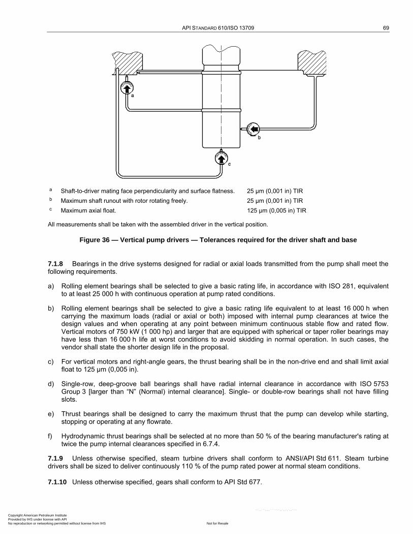
API STANDARD 610/ISO 13709 69
a Shaft-to-driver mating face perpendicularity and surface flatness. 25 µm (0,001 in) TIR
b Maximum shaft runout with rotor rotating freely. 25 µm (0,001 in) TIR
c Maximum axial float. 125 µm (0,005 in) TIR
All measurements shall be taken with the assembled driver in the vertical position.
Figure 36 — Vertical pump drivers — Tolerances required for the driver shaft and base
7.1.8 Bearings in the drive systems designed for radial or axial loads transmitted from the pump shall meet the following requirements.
a) Rolling element bearings shall be selected to give a basic rating life, in accordance with ISO 281, equivalent to at least 25 000 h with continuous operation at pump rated conditions.
b) Rolling element bearings shall be selected to give a basic rating life equivalent to at least 16 000 h when carrying the maximum loads (radial or axial or both) imposed with internal pump clearances at twice the design values and when operating at any point between minimum continuous stable flow and rated flow. Vertical motors of 750 kW (1 000 hp) and larger that are equipped with spherical or taper roller bearings may have less than 16 000 h life at worst conditions to avoid skidding in normal operation. In such cases, the vendor shall state the shorter design life in the proposal.
c) For vertical motors and right-angle gears, the thrust bearing shall be in the non-drive end and shall limit axial float to 125 µm (0,005 in).
d) Single-row, deep-groove ball bearings shall have radial internal clearance in accordance with ISO 5753 Group 3 [larger than ―N‖ (Normal) internal clearance]. Single- or double-row bearings shall not have filling slots.
e) Thrust bearings shall be designed to carry the maximum thrust that the pump can develop while starting, stopping or operating at any flowrate.
f) Hydrodynamic thrust bearings shall be selected at no more than 50 % of the bearing manufacturer's rating at twice the pump internal clearances specified in 6.7.4.
7.1.9 Unless otherwise specified, steam turbine drivers shall conform to ANSI/API Std 611. Steam turbine drivers shall be sized to deliver continuously 110 % of the pump rated power at normal steam conditions.
7.1.10 Unless otherwise specified, gears shall conform to API Std 677.
Copyright American Petroleum Institute Provided by IHS under license with API
Not for ResaleNo reproduction or networking permitted without license from IHS
--`,,```,,,,````-`-`,,`,,`,`,,`---
70 CENTRIFUGAL PUMPS FOR PETROLEUM, PETROCHEMICAL AND NATURAL GAS INDUSTRIES
7.2 Couplings and guards
7.2.1 Unless otherwise specified, couplings and guards between drivers and driven equipment shall be supplied and mounted by the vendor with unit responsibility.
7.2.2 Unless otherwise specified, all-metal flexible element, spacer-type couplings manufactured in accordance with AGMA 9000 Class 9 shall be provided. Additionally, couplings shall comply with the following.
a) Flexible elements shall be of corrosion-resistant material.
b) Couplings shall be designed to positively retain the spacer if a flexible element ruptures.
NOTE 1 The use of bolt heads or flexible element fasteners alone to retain the spacer if a flexible membrane ruptures might not provide adequate support because they are subject to wear if and when failure occurs.
c) Coupling hubs shall be steel.
d) The distance between the pump and driver shaft ends (distance between shaft ends, or DBSE) shall be greater than the seal cartridge length for all pumps other than OH type or at least 125 mm (5 in) and shall permit removal of the coupling, bearing housing, bearings, seal and rotor, as applicable, without disturbing the driver, driver coupling hub, pump coupling hub or the suction and discharge piping. For Types BB and VS pumps, this dimension, DBSE, shall always be greater than the total seal length, l, listed in Table 7, and shall be included on the pump data sheet (Annex N).
NOTE 2 The DBSE dimension usually corresponds to the nominal coupling spacer length.
e) Provision shall be made for the attachment of alignment equipment without the requirement to remove the spacer or dismantle the coupling in any way.
NOTE 3 One way of achieving this is to provide at least 25 mm (1 in) of bare shaft between the coupling hub and the bearing housing where alignment brackets can be located.
f) Couplings operating at speeds in excess of 3 800 r/min shall meet the requirements of ISO 10441 or ANSI/API Std 671/ISO 10441 for component balancing and assembly balance check.
7.2.3 If specified, couplings shall be balanced to ISO 1940-1, grade G6.3.
7.2.4 If specified, couplings shall meet the requirements of ISO 14691, ISO 10441 or ANSI/API Std 671/ISO 10441.
7.2.5 Information on shafts, keyway dimensions (if any), and shaft end movements due to end play and thermal effects shall be furnished to the vendor supplying the coupling.
7.2.6 Flexible couplings shall be keyed to the shaft. Keys, keyways and fits shall conform to AGMA 9002, Commercial Class. Shaft coupling keyways shall be cut to accommodate a rectangular cross section key. Sled-runner type keys and keyways shall not be provided. Keys shall be fabricated and fitted to minimize unbalance.
7.2.7 Couplings and coupling to shaft junctures shall be rated for at least the maximum driver power, including the driver service factor.
7.2.8 For shaft diameters greater than 60 mm (2,5 in) and if it is necessary to remove the coupling hub to service the mechanical seal, the hub shall be mounted with a taper fit. The coupling fit taper for keyed couplings shall be 1 in 16 [60 mm/m (0,75 in/ft), diametral]. Other mounting methods and tapers shall be agreed upon by the purchaser and the vendor. Coupling hubs with cylindrical bores may be supplied with slip fits to the shaft and set screws that bear on the key.
Appropriate assembly and maintenance procedures should be used to assure that taper fit couplings have an interference fit. Slip fits on cylindrical bores allow adjustment of the coupling axial position in the field without application of heat.
Copyright American Petroleum Institute Provided by IHS under license with API
Not for ResaleNo reproduction or networking permitted without license from IHS
--`,,```,,,,````-`-`,,`,,`,`,,`---
API STANDARD 610/ISO 13709 71
7.2.9 Coupling hubs designed for interference fits to the shaft shall be furnished with tapped puller holes at least 10 mm (0,38 in) in diameter to aid in removal.
7.2.10 If specified, couplings shall be fitted hydraulically.
7.2.11 If specified, couplings shall be fitted with a proprietary clamping device. Acceptable clamping devices may include tapered bushes, frictional locking assemblies and shrink discs. The vendor responsible for the final machining of the hub bores shall select a suitable rating/size device to suit the coupling and the application.
Care should be exercised in the selection of these devices, as some are not inherently self-centring and may introduce eccentricity and unbalance into the coupling assembly. This effect shall be evaluated and allowed for when determining coupling potential unbalance.
7.2.12 If the vendor is not required to mount the driver, the fully machined half-coupling shall be delivered to the driver manufacturer's plant or any other designated location, together with the necessary instructions for mounting the half-coupling on the driver shaft.
7.2.13 Each coupling shall have a coupling guard that is removable without disturbing the coupled elements. Each coupling guard shall meet the following requirements:
a) enclose the coupling and the shafts to prevent personnel from contacting moving parts during operation of the equipment train; allowable access dimensions shall comply with specified standards, such as ISO 14120, EN 953 or ANSI/AMT B15.1;
b) be constructed with sufficient stiffness (rigidity) to withstand a 900 N (200 lbf) static point load in any direction without the guard contacting moving parts;
c) be fabricated from sheet (solid or perforated), plate, or expanded metal; any openings shall conform to ISO 14120, EN 953 or ANSI/AMT B15.1, but in no case shall exceed 10 mm (0,375 in); guards of woven wire shall not be used;
d) be constructed of steel, brass, aluminium or non-metallic (polymer) materials, as suitable;
7.2.14 If specified, coupling guards shall be constructed of an agreed spark-resistant material (see 6.10.2.6, note).
7.2.15 If specified for coupling guards with potentially explosive atmospheres, an ―ignition hazard assessment‖ (risk analysis) in accordance with EN 13463-1 shall be conducted and a suitable report provided.
7.3 Baseplates
7.3.1 Single-piece drain-rim or drain-pan baseplates shall be furnished for horizontal pumps. The purchaser shall specify the rim or pan type as follows:
a) drain rim surrounding the entire baseplate;
b) drain pan surrounding the entire baseplate;
c) partial drain pan that covers the entire width of the baseplate.
The rim or pan of the baseplate shall be sloped at least 1 in 120 towards the pump end, where a tapped drain opening of at least DN 50 (NPS 2) shall be located to effect complete drainage.
Copyright American Petroleum Institute Provided by IHS under license with API
Not for ResaleNo reproduction or networking permitted without license from IHS
--`,,```,,,,````-`-`,,`,,`,`,,`---

72 CENTRIFUGAL PUMPS FOR PETROLEUM, PETROCHEMICAL AND NATURAL GAS INDUSTRIES
7.3.2 The baseplate shall extend under the pump and drive-train components so that any leakage is contained within the baseplate. To minimize accidental damage to components, all pipe joints and pipe flange faces, including pump suction and discharge flanges, shall be within the drain-pan or drain-rim collection area. All other projections of the equipment supplied shall fall within the maximum perimeter of the baseplate. Oversized junction boxes may overhang the perimeter of the baseplate with the purchaser's approval.
7.3.3 If driver and pump size permit, baseplates shall have standardized dimensions as given in Annex D and shall be designed for grouting. These baseplates shall be referred to as ―Standard baseplates, numbers 0,5 to 12.‖
7.3.4 The height of the pump-shaft centreline above the baseplate shall be minimized. Adequate clearance shall be provided between the casing drain connection and the baseplate so that drain piping the same size as the connection can be installed without the use of a street (male-female) elbow.
7.3.5 Mounting pads shall be provided for the pump and all drive-train components, such as motors and gears. The pads shall be larger than the foot of the mounted equipment, including extra width of shims under drive-train components, to allow levelling of the baseplate without removal of the equipment. The pads shall be fully machined flat and parallel. Corresponding surfaces shall be in the same plane within 150 µm/m (0,002 in/ft) of distance between the pads.
If specified, this requirement shall be demonstrated in the pump-vendor's shop prior to mounting of the equipment and with the baseplate supported at the foundation bolt holes only. This demonstration can be performed only when the clamps are released in the milling machine after completion of machining.
Installed baseplate flatness can be affected by transportation, handling and installation procedures beyond the vendor's scope. Installation practices in API RP 686 should be followed.
7.3.6 All pads for drive-train components shall be machined to allow for the installation of shims at least 3 mm (0,12 in) thick under each component. If the vendor mounts the components, a set of stainless steel shims (shim packs) at least 3 mm (0,12 in) thick shall be furnished. Shim packs shall not be thicker than 13 mm (0,5 in) nor contain more than 5 shims. All shim packs shall straddle the hold-down bolts and vertical jackscrews, and extend at least 5 mm (1/4 in) beyond the outer edges of the equipment feet. If the vendor does not mount the components, the pads shall not be drilled and shims shall not be provided. Shims shall not be used under the pump.
If specified, in addition to shim packs, a stainless steel spacer plate of not less than 5 mm (0,200 in) thickness, machined on both sides, and of the same length and width as the specific mounting feet, shall be furnished and installed under all equipment feet, including the pump, driver, and any speed increaser or reducer.
7.3.7 All joints, including deck plate to structural members, shall be continuously seal-welded on both sides to prevent crevice corrosion. Stitch welding, top or bottom, is unacceptable.
7.3.8 The bottom of the baseplate between structural members shall be open if the baseplate is designed to be installed and grouted to a concrete foundation. Accessibility shall be provided for grouting under all load-carrying members. The bottom of the baseplate shall be in one plane to permit use of a single level foundation.
7.3.9 The underside of fabricated baseplates beneath the pump and driver supports shall be welded to reinforcing cross-members, and the members shall be shaped to lock positively into the grout.
7.3.10 All baseplates shall be provided with at least one grout hole having a clear area of at least 125 cm2 (19 in2) and no dimension less than 75 mm (3 in) in each bulkhead section. These holes shall be located to permit filling the entire cavity under the baseplate without creating air pockets. If practical, the holes shall be accessible for grouting with the pump and driver installed on the baseplate. Grout holes in the drip pan area shall have 13 mm (0,5 in) raised lip edges. If the holes are located in an area where liquids can impinge on the exposed grout, metallic covers with a minimum thickness of 1,5 mm (0,06 in, 16 gauge) shall be provided. Vent holes at least 13 mm (0,5 in) in diameter shall be provided at the highest point in each bulkhead section of the baseplate.
7.3.11 The outside corners of the baseplate in contact with the grout shall have at least 50 mm (2 in) radii in the plan view (see Figure D.1).
Copyright American Petroleum Institute Provided by IHS under license with API
Not for ResaleNo reproduction or networking permitted without license from IHS
--`,,```,,,,````-`-`,,`,,`,`,,`---
API STANDARD 610/ISO 13709 73
7.3.12 Unless otherwise specified, the vendor shall commercially sand-blast, in accordance with ISO 8501 Grade Sa2 or SSPC SP 6, all grout contact surfaces of the baseplate, and coat those surfaces with a primer compatible with epoxy grout.
Grouts other than epoxy can require alternative surface preparation. Full bond-strength of epoxy is not generally necessary (7.3.9).
7.3.13 If specified, the baseplate and pedestal support assembly shall be sufficiently rigid to be mounted without grouting.
7.3.14 If specified, the baseplate shall be supplied without a deck plate, i.e. open deck design.
7.3.15 The baseplate shall be provided with lifting lugs for at least a four-point lift. Lifting the baseplate, complete with all equipment mounted, shall not permanently distort or otherwise damage the baseplate or the machinery mounted on it.
7.3.16 Lifting lugs attached to the equipment shall be designed using a maximum allowable stress of one-third of the specified minimum yield strength of the material.
7.3.17 Transverse and axial alignment positioning jackscrews shall be provided for drive-train components having a mass greater that 225 kg (500 lb) to facilitate transverse horizontal and longitudinal adjustments. The lugs holding these positioning screws shall be attached to the baseplate so that the lugs do not interfere with the installation or removal of the component. These screws shall be at least M12 (1/2"-13). To prevent distortion, machining of mounting pads shall be deferred until welding on the baseplate in close proximity to the mounting pads has been completed.
7.3.18 Vertical levelling screws shall be provided on the outside perimeter of the baseplate adjacent to each anchor bolt to minimize distortion during the process of installation and to carry the weight of the baseplate, pump, and drive-train components without excessive deflection.
7.3.19 The vendor shall provide for sufficient anchor bolting to withstand nozzle reaction forces during pump start-up and operation.
Anchor bolts are in the purchaser's scope.
7.3.20 To minimize misalignment of the pump and driver shafts due to piping load effects, the pump and its baseplate shall be constructed with sufficient structural stiffness to limit displacement of the pump shaft at the drive end of the shaft or at the register fit of the coupling hub to the values shown in Table 13. These values are the acceptance criteria for the nozzle load test in 7.3.21. Grout shall not be used as a means of obtaining the required stiffness during this test.
It is recognized that grout can significantly increase the stiffness of the baseplate assembly; by neglecting this effect, the adequacy of the baseplate can easily be verified at the vendor's shop. It is also noted that thermal growth, piping fabrication errors, and alignment error all contribute to the actual deflection values achieved in the field. Adherence to the nozzle load values in Table 5 limits the total deflection at the pump and drive shaft ends to approximately 250 µm (0,010 in) (see Annex F).
7.3.21 If specified, the vendor shall test to demonstrate that the pump and its baseplate assembly, anchored at foundation bolt hole locations, are in compliance with 7.3.20. The pump casing shall be subjected to moments MYc and MZc applied to either nozzle, but not both, such that the corresponding shaft displacements can be measured and recorded. MYc and MZc shall not be applied simultaneously to either nozzle. The shaft displacement measurements shall be absolute (not relative to the baseplate). For record purposes, the vendor's test data shall include a schematic drawing of test set-up, the calculated moment loads (MYc and MZc), and the applied moment loads and their corresponding displacements at the drive end of the pump shaft.
Copyright American Petroleum Institute Provided by IHS under license with API
Not for ResaleNo reproduction or networking permitted without license from IHS
--`,,```,,,,````-`-`,,`,,`,`,,`---
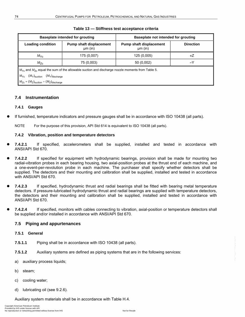
74 CENTRIFUGAL PUMPS FOR PETROLEUM, PETROCHEMICAL AND NATURAL GAS INDUSTRIES
Table 13 — Stiffness test acceptance criteria
Baseplate intended for grouting Baseplate not intended for grouting
Loading condition Pump shaft displacement µm (in)
Pump shaft displacement µm (in)
Direction
MYc 175 (0,007) 125 (0,005) Z
MZc 75 (0,003) 50 (0,002) Y
MYc and MZc equal the sum of the allowable suction and discharge nozzle moments from Table 5.
MYc (MY)suction (MY)discharge
MZc (MZ)suction (MZ)discharge
7.4 Instrumentation
7.4.1 Gauges
If furnished, temperature indicators and pressure gauges shall be in accordance with ISO 10438 (all parts).
NOTE For the purpose of this provision, API Std 614 is equivalent to ISO 10438 (all parts).
7.4.2 Vibration, position and temperature detectors
7.4.2.1 If specified, accelerometers shall be supplied, installed and tested in accordance with ANSI/API Std 670.
7.4.2.2 If specified for equipment with hydrodynamic bearings, provision shall be made for mounting two radial-vibration probes in each bearing housing, two axial-position probes at the thrust end of each machine, and a one-event-per-revolution probe in each machine. The purchaser shall specify whether detectors shall be supplied. The detectors and their mounting and calibration shall be supplied, installed and tested in accordance with ANSI/API Std 670.
7.4.2.3 If specified, hydrodynamic thrust and radial bearings shall be fitted with bearing metal temperature detectors. If pressure-lubricated hydrodynamic thrust and radial bearings are supplied with temperature detectors, the detectors and their mounting and calibration shall be supplied, installed and tested in accordance with ANSI/API Std 670.
7.4.2.4 If specified, monitors with cables connecting to vibration, axial-position or temperature detectors shall be supplied and/or installed in accordance with ANSI/API Std 670.
7.5 Piping and appurtenances
7.5.1 General
7.5.1.1 Piping shall be in accordance with ISO 10438 (all parts).
7.5.1.2 Auxiliary systems are defined as piping systems that are in the following services:
a) auxiliary process liquids;
b) steam;
c) cooling water;
d) lubricating oil (see 9.2.6).
Auxiliary system materials shall be in accordance with Table H.4.
Copyright American Petroleum Institute Provided by IHS under license with API
Not for ResaleNo reproduction or networking permitted without license from IHS
--`,,```,,,,````-`-`,,`,,`,`,,`---
API STANDARD 610/ISO 13709 75
NOTE Auxiliary connections are discussed in 6.4.3.
7.5.1.3 The piping systems shall be fully assembled and installed. If this requirement causes difficulty in shipping and handling, alternative arrangements are acceptable with purchaser approval.
7.5.1.4 If specified, barrier/buffer fluid reservoirs shall be designed for mounting off the pump baseplate and shall be shipped separately. These reservoirs shall be fully assembled, except that the fluid-circulation tubing shall not be supplied.
7.5.1.5 The vendor shall furnish and locate all piping systems, including mounted appurtenances, within the confines of the baseplate.
7.5.1.6 If specified, each piping system shall be manifolded to a single purchaser's inlet or outlet connection near the edge and within the confines of the baseplate.
NOTE The data sheet allows selection of this option for vent, cooling water and drain connections.
7.5.1.7 The bolting requirements of 6.1.30 apply to the connection of auxiliary piping to the equipment. Flange fasteners on stainless steel piping systems in lubricating oil service need not be stainless steel unless specified. If the purchaser does not specify stainless steel fasteners, they shall be low-alloy steel (e.g. ASTM A193/A193M, Grade B7) and the purchaser shall specify whether they shall be coated (such as by PTFE coating or galvanizing in accordance with ISO 10684 or ASTM A153/A153M) or painted.
7.5.1.8 Plugs shall comply with 6.4.3.11.
7.5.2 Auxiliary process liquid piping
7.5.2.1 Auxiliary process-liquid piping includes vent lines, drain lines, balance lines, product flushing lines and lines for injection of external fluid.
7.5.2.2 Piping components shall have a pressure-temperature rating at least equal to MAWP of the pump casing, but in no case less than ISO 7005 PN50 (ASME Class 300) flange at ambient temperature (6.3.5).
7.5.2.3 Piping and components subject to the process liquid shall have a corrosion/erosion resistance equal to or better than that of the casing. Otherwise, all components shall be steel.
7.5.2.4 Orifice openings shall not be less than 3 mm (0,12 in) in diameter. Orifice hole size shall be stamped on the orifice plate. The purchaser shall specify orifice tagging or labelling requirements.
7.5.2.5 Drain valves and a drain manifold shall be supplied for pumps that require more than one drain connection. The drain manifold shall be inside the drain pan limits.
Drain valves are not required for pumps that can be drained with one drain connection. The vendor shall provide space on the baseplate for a purchaser-supplied drain valve inside the pump drain pan or drain rim.
7.5.2.6 Unless valves are specified, threaded vent and drain connections shall be plugged. Carbon steel plugs shall be used with cast iron casings.
7.5.2.7 If heating or cooling is provided, each exchanger component shall be suitable for the process liquid and cooling water to which it is exposed.
7.5.2.8 The purchaser shall specify where flanges are required in place of socket-welded unions. With purchaser approval, socket-welded unions may be used in place of flanges at the first connection from the seal gland.
NOTE Threaded connections are allowed on gland connections (see 6.4.3.11). If the remainder of the piping arrangement is flanged, repeated assembly and disassembly can overstress this threaded connection, since adjustment is possible only in 90° increments. Socket-welded unions supplied in stainless steel tend to leak after repeated assembly and disassembly.
7.5.2.9 Threaded piping joints may be used only on seal glands, instrumentation connections and for pumps of cast iron construction (Class I-1 or I-2 in Table H.1).
Copyright American Petroleum Institute Provided by IHS under license with API
Not for ResaleNo reproduction or networking permitted without license from IHS
--`,,```,,,,````-`-`,,`,,`,`,,`---
76 CENTRIFUGAL PUMPS FOR PETROLEUM, PETROCHEMICAL AND NATURAL GAS INDUSTRIES
7.5.2.10 Transmitters and pressure gauges shall have block-and-bleed valves.
7.5.3 Cooling-water piping
7.5.3.1 The arrangement of cooling-water piping shall conform to Figures B.2 to B.7, as applicable.
7.5.3.2 The cooling-water piping shall be designed for the conditions in 6.1.20.
7.6 Special tools
7.6.1 If special tools and fixtures are required to disassemble, assemble, or maintain the unit, they shall be included in the quotation and furnished as part of the initial supply of the machine. For multiple-unit installations, the requirements for quantities of special tools and fixtures shall be agreed upon by the purchaser and the vendor. These or similar special tools shall be used during shop assembly and post-test disassembly of the equipment.
7.6.2 If special tools are provided, they shall be packaged in separate, rugged metal boxes and marked ―special tools for (tag/item number)‖. Each tool shall be stamped or tagged to indicate its intended use.
8 Inspection, testing, and preparation for shipment
8.1 General
8.1.1 The purchaser shall specify the extent of his participation in the inspection and testing.
a) If shop inspection and testing have been specified, the purchaser and the vendor shall coordinate manufacturing hold points and inspector's visits.
b) The expected dates of testing shall be communicated at least 30 days in advance and the actual dates confirmed as agreed. Unless otherwise agreed, the vendor shall give at least five working days advanced notification of a witnessed or observed inspection or test.
For smaller pumps where set-up and test time is short, five days notice may require the removal of the pump from the test stand between preliminary and witness tests.
All witnessed inspections and tests are hold points. For observed tests, the purchaser should expect to be in the factory longer than for a witnessed test.
c) If specified, witnessed mechanical and performance tests shall require a written notification of a successful preliminary test. The vendor and purchaser shall agree whether or not to maintain the machine test set-up or whether the machine can be removed from the test stand between the preliminary and witnessed tests.
Many purchasers prefer not to have preliminary tests prior to witnessed tests, in order to understand any difficulties encountered during testing. If this is the case, purchasers should make it clear to the vendor.
8.1.2 The vendor shall notify sub-vendors of the purchaser's inspection and testing requirements.
8.1.3 After advance notification to the vendor by the purchaser, the purchaser's representative shall have reasonable access to all vendor and sub-vendor plants where manufacturing, testing or inspection of the equipment is in progress. The level of access shall be agreed upon.
8.1.4 Equipment, materials and utilities for the specified inspections and tests shall be provided by the vendor.
8.1.5 If specified, the purchaser's representative, the vendor's representative, or both, shall indicate compliance in accordance with an inspector's checklist such as that provided in Annex E by initialling, dating and submitting the completed checklist to the purchaser before shipment.
8.1.6 The purchaser's representative shall have access to the vendor's quality programme for review.
Copyright American Petroleum Institute Provided by IHS under license with API
Not for ResaleNo reproduction or networking permitted without license from IHS
--`,,```,,,,````-`-`,,`,,`,`,,`---

API STANDARD 610/ISO 13709 77
8.2 Inspection
8.2.1 General
8.2.1.1 The vendor shall keep the following data available for at least 20 years:
a) necessary or specified certification of materials, such as mill test reports;
b) test data and results to verify that the requirements of the specification have been met;
c) if specified, details of all repairs and records of all heat-treatment performed as part of a repair procedure;
d) results of quality control tests and inspections;
e) as-built running clearances;
f) other data specified by the purchaser or required by applicable codes and regulations (see 10.3.1 and 10.3.2).
8.2.1.2 Pressure-containing parts shall not be painted until the specified inspection and testing of the parts is complete.
8.2.1.3 In addition to the requirements of 6.12.1.5, the purchaser may specify the following:
a) parts that shall be subjected to surface and subsurface examinations;
b) type of examination required, such as magnetic-particle, liquid-penetrant, radiographic and ultrasonic examinations.
8.2.1.4 All preliminary running tests and mechanical checks shall be completed by the vendor before the purchaser's final inspection.
8.2.2 Pressure-casing materials inspection
8.2.2.1 Unless otherwise specified, pressure-casing materials shall be inspected in accordance with the requirements of Table 14.
NOTE Although the pump is designed to meet specific pressure and temperature requirements and the casing is hydrostatically tested in accordance with the requirements of this International Standard, this alone does not guarantee that the material is of a suitable quality for the service. Casting quality can be affected by considerable variations in material processing. Material standards, such as ASTM, provide minimum requirements for the material itself, but castings can be subject to areas of shrinkage, gas porosity, hot tears, sand inclusions, improper weld repairs, etc. In addition, some materials are prone to grain boundary tears or cracks that can propagate under in-service stresses caused by temperature, pressure, vibration and pipe strain.
Copyright American Petroleum Institute Provided by IHS under license with API
Not for ResaleNo reproduction or networking permitted without license from IHS
--`,,```,,,,````-`-`,,`,,`,`,,`---
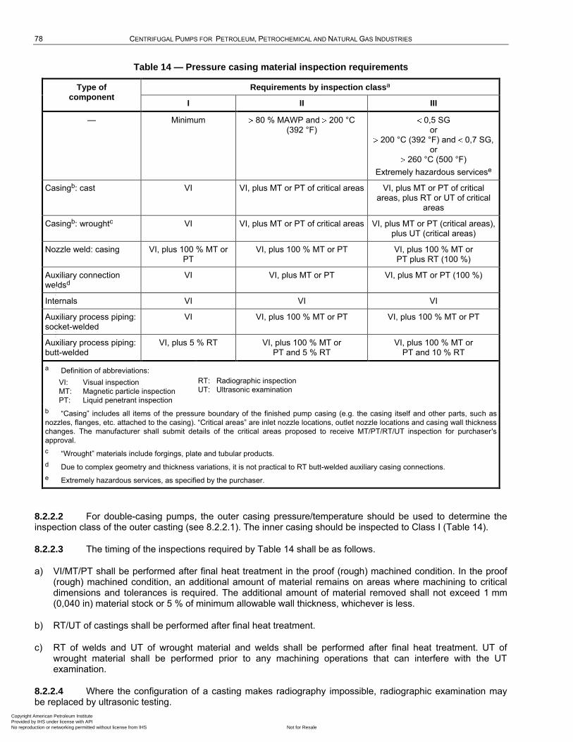
78 CENTRIFUGAL PUMPS FOR PETROLEUM, PETROCHEMICAL AND NATURAL GAS INDUSTRIES
Table 14 — Pressure casing material inspection requirements
Type of component
Requirements by inspection classa
I II III
— Minimum 80 % MAWP and 200 °C (392 °F)
0,5 SG or
200 °C (392 °F) and 0,7 SG, or
260 °C (500 °F)
Extremely hazardous servicese
Casingb: cast VI VI, plus MT or PT of critical areas VI, plus MT or PT of critical areas, plus RT or UT of critical
areas
Casingb: wroughtc VI VI, plus MT or PT of critical areas VI, plus MT or PT (critical areas), plus UT (critical areas)
Nozzle weld: casing VI, plus 100 % MT or PT
VI, plus 100 % MT or PT VI, plus 100 % MT or PT plus RT (100 %)
Auxiliary connection weldsd
VI VI, plus MT or PT VI, plus MT or PT (100 %)
Internals VI VI VI
Auxiliary process piping: socket-welded
VI VI, plus 100 % MT or PT VI, plus 100 % MT or PT
Auxiliary process piping: butt-welded
VI, plus 5 % RT VI, plus 100 % MT or PT and 5 % RT
VI, plus 100 % MT or PT and 10 % RT
a Definition of abbreviations:
VI: Visual inspection
MT: Magnetic particle inspection
PT: Liquid penetrant inspection
RT: Radiographic inspection
UT: Ultrasonic examination
b ―Casing‖ includes all items of the pressure boundary of the finished pump casing (e.g. the casing itself and other parts, such as
nozzles, flanges, etc. attached to the casing). ―Critical areas‖ are inlet nozzle locations, outlet nozzle locations and casing wall thickness
changes. The manufacturer shall submit details of the critical areas proposed to receive MT/PT/RT/UT inspection for purchaser's
approval.
c ―Wrought‖ materials include forgings, plate and tubular products.
d Due to complex geometry and thickness variations, it is not practical to RT butt-welded auxiliary casing connections.
e Extremely hazardous services, as specified by the purchaser.
8.2.2.2 For double-casing pumps, the outer casing pressure/temperature should be used to determine the inspection class of the outer casting (see 8.2.2.1). The inner casing should be inspected to Class I (Table 14).
8.2.2.3 The timing of the inspections required by Table 14 shall be as follows.
a) VI/MT/PT shall be performed after final heat treatment in the proof (rough) machined condition. In the proof (rough) machined condition, an additional amount of material remains on areas where machining to critical dimensions and tolerances is required. The additional amount of material removed shall not exceed 1 mm (0,040 in) material stock or 5 % of minimum allowable wall thickness, whichever is less.
b) RT/UT of castings shall be performed after final heat treatment.
c) RT of welds and UT of wrought material and welds shall be performed after final heat treatment. UT of wrought material shall be performed prior to any machining operations that can interfere with the UT examination.
8.2.2.4 Where the configuration of a casting makes radiography impossible, radiographic examination may be replaced by ultrasonic testing.
Copyright American Petroleum Institute Provided by IHS under license with API
Not for ResaleNo reproduction or networking permitted without license from IHS
--`,,```,,,,````-`-`,,`,,`,`,,`---
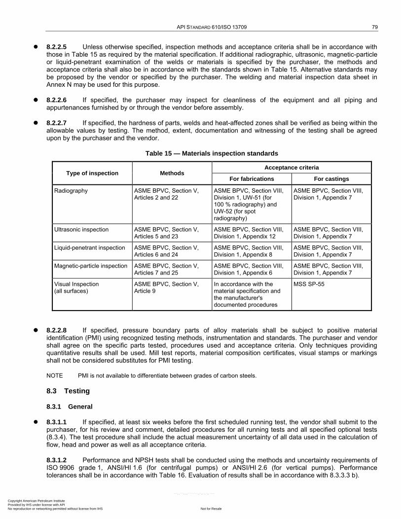
API STANDARD 610/ISO 13709 79
8.2.2.5 Unless otherwise specified, inspection methods and acceptance criteria shall be in accordance with those in Table 15 as required by the material specification. If additional radiographic, ultrasonic, magnetic-particle or liquid-penetrant examination of the welds or materials is specified by the purchaser, the methods and acceptance criteria shall also be in accordance with the standards shown in Table 15. Alternative standards may be proposed by the vendor or specified by the purchaser. The welding and material inspection data sheet in Annex N may be used for this purpose.
8.2.2.6 If specified, the purchaser may inspect for cleanliness of the equipment and all piping and appurtenances furnished by or through the vendor before assembly.
8.2.2.7 If specified, the hardness of parts, welds and heat-affected zones shall be verified as being within the allowable values by testing. The method, extent, documentation and witnessing of the testing shall be agreed upon by the purchaser and the vendor.
Table 15 — Materials inspection standards
Type of inspection Methods Acceptance criteria
For fabrications For castings
Radiography ASME BPVC, Section V, Articles 2 and 22
ASME BPVC, Section VIII, Division 1, UW-51 (for 100 % radiography) and UW-52 (for spot radiography)
ASME BPVC, Section VIII, Division 1, Appendix 7
Ultrasonic inspection ASME BPVC, Section V, Articles 5 and 23
ASME BPVC, Section VIII, Division 1, Appendix 12
ASME BPVC, Section VIII, Division 1, Appendix 7
Liquid-penetrant inspection ASME BPVC, Section V, Articles 6 and 24
ASME BPVC, Section VIII, Division 1, Appendix 8
ASME BPVC, Section VIII, Division 1, Appendix 7
Magnetic-particle inspection ASME BPVC, Section V, Articles 7 and 25
ASME BPVC, Section VIII, Division 1, Appendix 6
ASME BPVC, Section VIII, Division 1, Appendix 7
Visual Inspection (all surfaces)
ASME BPVC, Section V, Article 9
In accordance with the material specification and the manufacturer's documented procedures
MSS SP-55
8.2.2.8 If specified, pressure boundary parts of alloy materials shall be subject to positive material identification (PMI) using recognized testing methods, instrumentation and standards. The purchaser and vendor shall agree on the specific parts tested, procedures used and acceptance criteria. Only techniques providing quantitative results shall be used. Mill test reports, material composition certificates, visual stamps or markings shall not be considered substitutes for PMI testing.
NOTE PMI is not available to differentiate between grades of carbon steels.
8.3 Testing
8.3.1 General
8.3.1.1 If specified, at least six weeks before the first scheduled running test, the vendor shall submit to the purchaser, for his review and comment, detailed procedures for all running tests and all specified optional tests (8.3.4). The test procedure shall include the actual measurement uncertainty of all data used in the calculation of flow, head and power as well as all acceptance criteria.
8.3.1.2 Performance and NPSH tests shall be conducted using the methods and uncertainty requirements of ISO 9906 grade 1, ANSI/HI 1.6 (for centrifugal pumps) or ANSI/HI 2.6 (for vertical pumps). Performance tolerances shall be in accordance with Table 16. Evaluation of results shall be in accordance with 8.3.3.3 b).
Copyright American Petroleum Institute Provided by IHS under license with API
Not for ResaleNo reproduction or networking permitted without license from IHS
--`,,```,,,,````-`-`,,`,,`,`,,`---
80 CENTRIFUGAL PUMPS FOR PETROLEUM, PETROCHEMICAL AND NATURAL GAS INDUSTRIES
8.3.1.3 Mechanical seals shall not be used during the hydrostatic test but shall be used during all running or performance tests.
8.3.2 Hydrostatic test
8.3.2.1 The intent of a hydrostatic test of a centrifugal pump casing is to ensure that the design and construction of the pump pressure containing components and joints are leak-free from ambient conditions to the maximum operation conditions defined on the data sheet.
8.3.2.2 All pressure-casing components shall be hydrostatically tested as assemblies. The test shall be conducted with liquid at a minimum of 1,5 times the maximum allowable working pressure, MAWP.
8.3.2.3 The test set-up and/or apparatus shall not provide stiffening that improves the integrity of any joint.
8.3.2.4 Gaskets used during hydrostatic testing of an assembled pressure casing, less seal glands, shall be of the same design as those supplied with the pump and shall be installed without sealant.
8.3.2.5 The test liquid shall be at a temperature higher than the nil-ductility transition temperature of the material being tested.
8.3.2.6 If the part tested will operate at a temperature at which the strength of a material is below the strength of that material at the testing temperature, the hydrostatic test pressure shall be multiplied by a factor obtained by dividing the allowable working stress for the material at the testing temperature by that at the rated operating temperature. The stress values used shall be determined in accordance with 6.3.4. For piping, the stress shall conform to ISO 15649 or ASME B31.3, as specified. The pressure thus obtained shall then be the minimum pressure at which the hydrostatic test shall be performed. The data sheets shall list actual hydrostatic test pressures.
8.3.2.7 The hydrostatic test liquid shall include a wetting agent to reduce surface tension if one or more of the following conditions exists.
a) The liquid pumped has a relative density (specific gravity) of less than 0,7 at the pumping temperature.
b) The pumping temperature is higher than 260 °C (500 °F).
c) The casing is cast from a new or altered pattern.
d) The materials are known to have poor castability.
8.3.2.8 The chloride content of liquids used to test austenitic stainless steel materials shall not exceed 50 mg/kg (50 ppm). To prevent deposition of chlorides as a result of evaporative drying, all residual liquid shall be removed from the tested parts at the conclusion of the test.
NOTE Chloride content is limited in order to prevent stress-corrosion cracking.
8.3.2.9 Hydrostatic testing is permitted without the seal-gland plate or removable seal chamber installed. The mechanical seal shall not be included in the hydrostatic test of the pump case. Gland plates and removable seal chambers shall be tested as specified in ISO 21049. Seal chambers that are integral with the pump are not considered removable.
NOTE For the purposes of this provision, ANSI/API Std 682/ISO 21049, is equivalent to ISO 21049.
8.3.2.10 Austenitic or duplex stainless steel pressure-casing components may be hydrostatically tested in the proof (rough) machined condition. See 8.2.2.3.
Any areas that are machined after hydrostatic testing shall be identified on the hydrotest report.
NOTE Because of the residual stresses resulting from final liquid quenching and relatively low proportional limits inherent in these materials, small amounts of permanent deformation can occur at critical dimensions during hydrostatic testing. By allowing a small amount of material to remain at these critical areas during hydrostatic testing, the necessity to add material by welding to restore close-tolerance dimensions after hydrotest is avoided.
Copyright American Petroleum Institute Provided by IHS under license with API
Not for ResaleNo reproduction or networking permitted without license from IHS
--`,,```,,,,````-`-`,,`,,`,`,,`---
API STANDARD 610/ISO 13709 81
8.3.2.11 Tests shall be maintained for a sufficient period of time to permit complete examination of parts under pressure. The hydrostatic test shall be considered satisfactory if neither leaks nor seepage through the pressure-containing parts and joints occur within 30 min. Large, heavy, pressure-containing parts can require a longer testing period as agreed upon by the purchaser and the vendor. Seepage past internal closures required for testing of segmented cases and operation of a test pump to maintain pressure are acceptable.
8.3.2.12 Double-casing pumps, horizontal multistage pumps, integral-gear pumps (as described in 6.3.6), and other special-design pumps as approved by the purchaser may be segmentally tested. Seepage past internal closures required for testing of segmented cases and operation of a test pump to maintain pressure is acceptable.
8.3.2.13 Piping systems fabricated by welding shall be hydrostatically tested. Testing and stress levels shall be in accordance with ISO 15649 or ANSI/ASME B31.3 as specified.
NOTE It is not necessary to hydrostatically test piping systems assembled with tubing or threaded connections after assembly.
8.3.2.14 Unless otherwise specified, single-stage overhung-pump casing components with a radial joint (mean gasket diameter) 610 mm (24 in) in diameter or less may be hydrostatically tested as components or subassemblies provided that joint design integrity has been proven by qualification testing for the specific size of pump and pressure rating in question.
8.3.2.15 Cooling passages and components, including jackets for bearings, seal chambers, oil coolers and seal coolers, shall be tested at a minimum gauge pressure of 1 000 kPa (10 bar; 150 psi).
8.3.2.16 Steam, cooling-water and lubricating-oil piping, if fabricated by welding, shall be tested at 1,5 times maximum operating gauge pressure or 1 050 kPa (10,5 bar; 150 psi), whichever is greater.
8.3.3 Performance test
8.3.3.1 Unless otherwise specified, each pump shall be given a performance test.
8.3.3.2 The following requirements of a) through i) shall be met while the pump is operating on the test stand and before the performance test is performed.
a) The contract seals and bearings shall be used in the pump for the performance test.
b) If approved by the purchaser, substitute seals may be used during the performance test if needed to prevent damage to the contract seals or if the contract seals are not compatible with the test liquid. See ISO 21049:2004, 10.3.5.
c) The seal (or seals) shall not have a leakage rate during any phase of the pump performance test that is in excess of that specified in ISO 21049:2004, A.1.3, or as otherwise agreed by the vendor and purchaser. Any unacceptable leakage during the pump performance test requires a disassembly and repair to the seal. If the seal is disassembled or removed, the seal shall be retested with an air test of the pump using the criteria defined in 8.3.3.7 d).
When the pump is on the test stand and water is used as the test liquid, liquid seals suitable for testing on water shall exhibit no visible signs of leakage. ISO 21049:2004, A.1.3, should be reviewed to confirm that a zero-visible-leakage criterion is appropriate for the seals being tested. Notably, pressurized dual seals with high barrier-fluid pressures [greater than 4 000 kPa (40 bar; 600 psi)] should be reviewed.
NOTE For the purpose of this provision, ANSI/API Std 682/ISO 21049, is equivalent to ISO 21049.
d) If specified, seal leakage during test shall require the assembled pump and seal to be rerun to demonstrate satisfactory seal performance.
e) All lubricating-oil pressures, viscosities and temperatures shall be within the range of operating values recommended in the vendor's operating instructions for the specified unit being tested.
f) Bearings specified as normally lubricated from a pure oil-mist system shall be pre-lubricated prior to performance testing using a suitable hydrocarbon oil.
Copyright American Petroleum Institute Provided by IHS under license with API
Not for ResaleNo reproduction or networking permitted without license from IHS
--`,,```,,,,````-`-`,,`,,`,`,,`---
82 CENTRIFUGAL PUMPS FOR PETROLEUM, PETROCHEMICAL AND NATURAL GAS INDUSTRIES
g) All joints and connections shall be checked for tightness and any leaks shall be corrected.
h) All warning, protective and control devices used during the test shall be checked and adjusted as required.
i) Unless otherwise agreed, performance tests shall be performed using water at a temperature not exceeding 55 °C (130 °F).
8.3.3.3 Unless otherwise specified, the performance test shall be conducted as specified in a) through e) as follows.
a) The vendor shall take test data, including head, flowrate, power and vibration at a minimum of five points. These points will normally be
1) shutoff (no vibration data required),
2) minimum continuous stable flow (beginning of allowable operating region),
3) between 95 % and 99 % of rated flow,
4) between rated flow and 105 % of rated flow,
5) approximately the best efficiency flow (if rated flow is not within 5 % of best efficiency flowrate),
6) end of allowable operating region.
b) The test data shall be fit to a spline or appropriate polynomial (typically third or fourth order) for head and for power using a least squares method. The rated/guarantee flow shall be inserted into the resulting equation and a value for head and power calculated. These values shall be corrected for speed, viscosity and density (specific gravity). The corrected values of head and power shall be within the tolerance bands allowed in Table 16.
In the case of high-energy pumps (see 6.1.15), integral-gear and multistage pumps, it might not be feasible to test at shutoff.
c) Unless otherwise agreed, the test speed shall be within 3 % of the rated speed shown on the pump data sheet (see example in Annex N). Test results shall be corrected to rated speed.
d) The vendor shall maintain a complete, detailed log of all final tests and shall prepare the required number of copies, certified for correctness. Data shall include test curves and a summary of test performance data compared to guarantee points (see 10.2.4, 10.3.2.2 and example in Annex M).
e) If specified, in addition to formal submittal of final data in accordance with 10.3.2.2, curves and test data (corrected for speed, specific gravity and viscosity) shall be submitted within 24 h after completion of performance testing for purchaser's engineering review and acceptance prior to shipment.
Copyright American Petroleum Institute Provided by IHS under license with API
Not for ResaleNo reproduction or networking permitted without license from IHS
--`,,```,,,,````-`-`,,`,,`,`,,`---

API STANDARD 610/ISO 13709 83
Table 16 — Performance tolerances
Condition Rated point
% Shutoff
%
Rated differential head:
0 m to 75 m (0 ft to 250 ft) 3 10a
75 m to 300 m ( 250 ft to 1 000 ft) 3 8a
300 m (1 000 ft) 3 5a
Rated power 4b —
Efficiency c
Rated NPSH 0 —
a If a rising head flow curve is specified (see 6.1.11), the negative tolerance specified here shall be allowed only if the test curve still
shows a rising characteristic.
b With test results corrected to rated conditions [see 8.3.3.3 b)] for flow, speed, density (specific gravity) and viscosity, it is necessary
that the power not exceed 104 % of the rated value, from all causes (cumulative tolerances are not acceptable).
c The uncertainty of test efficiency by the test code specified is 2,5 %; therefore, efficiency is not included in the pump's rated
performance. In those applications where efficiency is of prime importance to the purchaser, a specific value and related tolerance
should be negotiated at the time of the order (see 8.3.3.4).
8.3.3.4 For higher-power pumps ( 1 MW), performance tolerances other than those in Table 16 can be appropriate. If specified, pump efficiency at rated flow shall be quoted to the tolerance given by the purchaser and shall be included in the pump's rated performance. If a tolerance is specified for rated efficiency, an additional test point as close to rated flow as practical shall be taken. The rated efficiency and tolerance shall be consistent with the test code being used, with particular attention to the uncertainty of efficiency determined by test to that code.
The purchaser should expect that adding efficiency with a specific tolerance to the pump's rated performance usually affects pump cost and delivery.
8.3.3.5 During the performance test, the requirements of a) through d) as follows shall be met.
a) Vibration values shall be recorded at each test point except shutoff during the test in accordance with 6.9.3.2. Vibration values shall not exceed those given in 6.9.3.6.
b) For ring and splash-oil systems, oil temperatures shall be recorded at the beginning and the end of the test. For pressurized systems, bearing metal temperatures shall be recorded at the beginning and the end of the test. The duration of the test shall be indicated on the test report.
c) Pumps shall operate within bearing temperature limits as defined in 6.10.2.4 and shall not display signs of unusual operation, such as noise caused by cavitation.
d) When operated at rated speed, pumps shall perform within the tolerances given in Table 16 [see 8.3.3.3 b)].
8.3.3.6 If specified, the performance test shall be conducted with test stand NPSHA controlled to no more than 110 % of the NPSHA specified on the data sheet.
NOTE It is the purpose of this test to evaluate pump performance with the specified NPSHA at pump suction.
8.3.3.7 The requirements of a) through d) as follows shall be met after the performance test is completed.
a) If it is necessary to dismantle a pump after the performance test for the sole purpose of machining impellers to meet the tolerances for differential head, no retest is required unless the reduction in diameter exceeds
Copyright American Petroleum Institute Provided by IHS under license with API
Not for ResaleNo reproduction or networking permitted without license from IHS
--`,,```,,,,````-`-`,,`,,`,`,,`---

84 CENTRIFUGAL PUMPS FOR PETROLEUM, PETROCHEMICAL AND NATURAL GAS INDUSTRIES
5 % of the original diameter. The diameter of the impeller at the time of shop test, as well as the final diameter of the impeller, shall be recorded on a certified shop test curve that shows the operating characteristics after the diameter of the impeller has been reduced.
b) If specified, disassembly of multistage pumps for any head adjustment (including less than 5 % diameter change) after test, shall be cause for retest.
c) If it is necessary to dismantle a pump for any other correction, such as hydraulic performance, NPSH or mechanical operation, the initial test shall not be acceptable, and the final performance test shall be run after the correction is made.
d) If it is necessary to disturb the mechanical seal assembly following the performance test, or if the test seal faces are replaced with the job seal faces, the final seal assembly shall be air-tested as follows:
1) pressurize each sealing section independently with clean air to a test gauge pressure of 172 kPa (1,72 bar; 25 psi);
2) isolate the test set-up from the pressurizing source and maintain the pressure for a minimum of 5 min, or
5 min per 30 l (1 ft3) of test volume, whichever is greater;
3) The maximum allowable pressure drop during the test shall be 14 kPa (0,14 bar; 2 psi).
8.3.3.8 Unless otherwise specified, pumps shall not be disassembled after final performance testing. The pump, including the seal chamber, shall be drained to the extent practical, filled with a water-displacing inhibitor within 4 h of testing and redrained.
8.3.4 Optional tests
8.3.4.1 General
If specified, the shop tests described in 8.3.4.2 through 8.3.4.7 shall be performed. Test details and required data (such as vibration and temperature data) shall be agreed upon by the purchaser and the vendor prior to conducting the tests.
8.3.4.2 Mechanical run test
8.3.4.2.1 If specified, the pump shall be run on the test stand at the rated flow until oil temperature stabilization (6.10.2.4) has been achieved.
8.3.4.2.2 If specified, the pump shall be mechanically run at the rated flow for 4 h.
8.3.4.3 NPSH required test
8.3.4.3.1 If specified, NPSH3 shall be determined at each test point identified in 8.3.3.3 a) except shut-off.
8.3.4.3.2 A 3 % drop in head (first stage head on pumps with two or more stages) shall be interpreted as indicating performance impairment, thus the terminology NPSH3. The first-stage head of pumps with two or more stages shall be measured using a separate connection to the first-stage discharge if possible. If this is not feasible, testing of the first stage only should be considered. With purchaser approval, first-stage head may be determined by dividing total developed head by the number of stages.
Copyright American Petroleum Institute Provided by IHS under license with API
Not for ResaleNo reproduction or networking permitted without license from IHS
--`,,```,,,,````-`-`,,`,,`,`,,`---

API STANDARD 610/ISO 13709 85
8.3.4.3.3 The NPSH required test shall determine the actual NPSH required at a 3 % head drop. Unless otherwise specified or agreed, curves shall be developed at constant flow by reducing the NPSHA to a point where the head curves break away from that developed with sufficient NPSHA (8.3.4.3.2) by at least 3 %. The NPSH required test shall start with at least the same NPSHA as the performance test and at least twice the NPSH3 shown on the proposal curve. The first two test points shall not differ by more than the uncertainty of the head measurement. If the second test point at the same flowrate shows a decrease in differential head then the NPSHA shall be increased to a value sufficient to establish two consecutive points of equal head. The first two points shall be separated by a minimum of 1 m (3 ft) of NPSHA. These NPSH3 curves shall be developed and submitted in accordance with Hydraulic Institute Standards (ANSI/HI 1.6) or ISO 9906, as specified. The test shall not proceed beyond a 20 % head breakdown (20 % of first-stage head for multistage pumps).
NOTE If 8.3.3.6 is specified, it is possible that the head has already been affected by insufficient NPSHA, so starting at a higher NPSHA is desirable.
8.3.4.3.4 NPSH3 at the rated point shall not exceed the quoted value (see Table 16). Dismantling to correct NPSH3 performance requires a retest (see 8.3.3.7 and 8.3.3.8).
8.3.4.4 Complete unit test
8.3.4.4.1 If specified, the pump and driver train, complete with all auxiliaries that make up the unit, shall be tested together. If specified, torsional vibration measurements shall be made to verify the vendor's analysis. The complete-unit test shall be performed in place of or in addition to separate tests of individual components specified by the purchaser.
8.3.4.4.2 The acceptable vibration limits of each component of the train shall be as per its applicable standards and specifications, except for reciprocating engines (in this case, limits shall be mutually agreed upon by purchaser, pump vendor and engine supplier).
8.3.4.5 Sound level test
If specified, sound level tests shall be performed as agreed between the purchaser and the vendor.
NOTE ISO 3740, ISO 3744, and ISO 3746 may be consulted for guidance.
8.3.4.6 Auxiliary equipment test
If specified, auxiliary equipment, such as oil systems, gears and control systems, shall be tested in the vendor's shop. Details of the auxiliary equipment test(s) shall be developed jointly by the purchaser and the vendor.
8.3.4.7 Bearing-housing resonance test
If a resonance test is specified, the bearing housing(s) shall be excited by impact or other suitable means with the pump unpiped, and the natural frequency(ies) shall be determined from the response. A separation margin shall exist between the natural frequency(ies) and the following excitation frequencies:
a) multiples of running speed, expressed in revolutions per minute: 1,0; 2,0; 3,0;
b) multiples of vane passing frequency: 1,0; 2,0.
Test acceptance criteria shall be agreed upon between the purchaser and the vendor.
Copyright American Petroleum Institute Provided by IHS under license with API
Not for ResaleNo reproduction or networking permitted without license from IHS
--`,,```,,,,````-`-`,,`,,`,`,,`---
86 CENTRIFUGAL PUMPS FOR PETROLEUM, PETROCHEMICAL AND NATURAL GAS INDUSTRIES
8.4 Preparation for shipment
8.4.1 Unless otherwise specified, equipment shall be prepared for domestic shipment. Domestic shipment preparation shall make the equipment suitable for outdoor storage for a period of at least six months with no disassembly required before operation except possibly inspection of bearings and seals. Preparation for longer storage or export shipment is more rigorous and, if specified, shall be provided by the vendor following agreed procedures.
8.4.2 The equipment shall be prepared for shipment after all testing and inspection has been completed and the equipment has been released by the purchaser. The preparation shall include that specified in 8.4.2.1 through 8.4.2.9.
8.4.2.1 Rotors shall be blocked if necessary. Blocked rotors shall be identified by means of corrosion-resistant tags attached with stainless steel wire.
8.4.2.2 Internal surfaces of bearing housings and carbon-steel oil-systems components shall be coated with an oil-soluble rust preventive that is compatible with the lubricating oil.
8.4.2.3 Bearing assemblies shall be fully protected from the entry of moisture and dirt. If vapour-phase inhibitor crystals in bags are installed in large cavities, the bags shall be attached in an accessible area for ease of removal. If applicable, bags shall be installed in wire cages attached to flanged covers and bag locations shall be indicated by corrosion-resistant tags attached with stainless steel wire.
8.4.2.4 Exterior surfaces, except for machined surfaces, shall be given at least one coat of the manufacturer's standard paint. The paint shall not contain lead or chromates. It is not necessary to paint stainless steel parts. The undersides of baseplates shall be prepared for grout in accordance with 7.3.12.
8.4.2.5 Exterior machined surfaces, except for corrosion-resistant material, shall be coated with a rust preventive.
8.4.2.6 Flanged openings shall be provided with metal closures at least 5 mm (0,19 in) thick, with elastomeric gaskets and at least four full-diameter bolts. For studded openings, all nuts required for the intended service shall be used to secure closures.
8.4.2.7 Threaded openings shall be provided with steel caps or steel plugs in accordance with 6.4.3.11.
8.4.2.8 Openings that have been bevelled for welding shall be provided with closures designed to prevent entrance of foreign materials and damage to the bevel.
8.4.2.9 Exposed shafts and shaft couplings shall be wrapped with waterproof, mouldable waxed cloth or volatile-corrosion inhibitor paper. The seams shall be sealed with oil-proof adhesive tape.
8.4.3 Auxiliary piping connections furnished on the purchased equipment shall be impression-stamped or permanently tagged to agree with the vendor's connection table or general arrangement drawing. Service and connection designations shall be indicated. Symbols for all pump connections, including plugged connections, shall be in accordance with Annex B.
8.4.4 Lifting points and lifting lugs shall be clearly identified.
8.4.5 The equipment shall be identified with item and serial numbers. Material shipped separately shall be identified with securely affixed, corrosion-resistant metal tags indicating the item and serial number of the equipment for which it is intended. Crated equipment shall be shipped with duplicate packing lists, one inside and one on the outside of the shipping container.
8.4.6 One copy of the manufacturer's standard installation manual shall be packed and shipped with the equipment.
8.4.7 The vendor shall provide the purchaser with API RP 686-compliant instructions for the preservation of the integrity of the storage preparation at the job site and before start-up.
Copyright American Petroleum Institute Provided by IHS under license with API
Not for ResaleNo reproduction or networking permitted without license from IHS
--`,,```,,,,````-`-`,,`,,`,`,,`---
API STANDARD 610/ISO 13709 87
8.4.8 Horizontal pumps, and all furnished drivers and auxiliaries, shall be shipped fully assembled on their baseplates, except as noted below. Coupling spacers with bolts and other items, such as minimum flow orifices that are not part of the assembled pumping unit, shall be separately boxed, tagged and securely attached to the baseplate.
8.4.9 Drivers for vertical pumps and horizontal drivers with a mass over 200 kg (450 lb) may be removed after shop mounting and alignment and shipped separately but alongside pump. Vertical pumps with suction cans shall be shipped with the suction cans (barrels) removed.
8.4.10 If it is necessary to ship other major components separately, prior purchaser approval is required.
8.4.11 Metal filter elements and screens shall be cleaned and reinstalled prior to shipment. Non-metallic filter elements shall be shipped and installed in an unused condition.
8.4.12 Suitable rust preventatives shall be oil-soluble and compatible with all pumped liquids.
9 Specific pump types
9.1 Single-stage overhung pumps
9.1.1 Horizontal (type OH2) pumps
9.1.1.1 Rear pump bearing housing supports are not permitted.
9.1.1.2 The distance between the pump and driver shaft ends (distance between shaft ends, or DBSE) shall permit removal of the coupling spacer and back pullout assembly without disturbing the driver, coupling hubs or casing.
9.1.1.3 If specified, the shaft flexibility index shall be calculated by the vendor in accordance with K.1 and stated on the data sheet.
The design and operation requirements for overhung pump rotors are detailed in several areas of this standard. K.1 lists these requirements and establishes a standardized process of calculating a shaft flexibility index that may be used to evaluate these latter parameters and to establish a baseline for the comparison of shaft flexibility.
9.1.2 Vertical in-line (type OH3) pumps
9.1.2.1 A flat contact surface shall be provided on the bottom of the casing to make the pump stable if freestanding on a pad or foundation. The ratio of the unit centre of gravity height to the contact surface width shall be no greater than 3:1. This stability shall be achieved through the design of the casing or by a permanent external stand.
9.1.2.2 Pumps shall be designed so that they can either float with the suction and discharge pipe, or be bolted to a pad or foundation.
Flange loading on the pump can increase if the purchaser elects to bolt the unit down. This should be addressed in the piping design.
9.1.2.3 A minimum DN 15 (NPS 1/2) tapped drain connection shall be provided so that no liquid collects on the cover or driver support.
9.1.2.4 The pump and seal chamber shall be continuously vented with a high point connection in either the seal chamber or seal flush piping. Purchaser approval is necessary for systems that require manual venting.
If venting to the atmosphere is not acceptable, the vent should be connected to the process piping at an elevation above the seal chamber.
Copyright American Petroleum Institute Provided by IHS under license with API
Not for ResaleNo reproduction or networking permitted without license from IHS
--`,,```,,,,````-`-`,,`,,`,`,,`---
88 CENTRIFUGAL PUMPS FOR PETROLEUM, PETROCHEMICAL AND NATURAL GAS INDUSTRIES
9.1.2.5 The distance between the pump and driver shaft ends (distance between shaft ends, or DBSE) shall permit removal of the coupling spacer and back pullout assembly without disturbing the driver, coupling hubs or casing.
9.1.2.6 If specified, a device that allows direct rigging or lifting of the back-pullout assembly from outside the motor support with the driver in place shall be provided.
9.1.2.7 With the purchaser's approval, bearing housings may be arranged for grease lubrication (6.11.4). The stabilized bearing-housing temperature shall not exceed 82 °C (180 °F) when operating at an ambient temperature of 43 °C (110 °F). Recommended greases shall be suitable for operation at these temperatures.
9.1.2.8 Drivers shall be aligned in the vendor's shop prior to shipment.
9.1.3 Integral gear-driven (type OH6) pumps
9.1.3.1 The impeller shall be keyed or splined to the gearbox output shaft.
9.1.3.2 Integral-gear pumps can require removal of the driver to allow disassembly of the rotor and the seal assembly.
9.1.3.3 Impeller type shall be selected for the application and may be open, semi-open, or fully enclosed.
9.1.3.4 The need for a rotor lateral analysis shall be determined as described in 9.2.4.1. A lateral analysis should be specified only for unique, new or critical pumps.
NOTE Lateral critical speeds can be of concern with type OH6 pumps. Normally, pumps of this type are thoroughly investigated during development, and typical rotor dynamics are available and applicable.
9.1.3.5 Single-piece hydrodynamic radial bearings may be used.
9.1.3.6 Temperature and pressure gauges mounted directly on the gearbox shall be in accordance with ISO 10438 (all parts) except that the diameter of the gauges shall be 50 mm (2,0 in). If specified, separable threaded solid-bar thermowells shall be supplied for temperature gauges.
9.1.3.7 Inducers, impellers and similar major rotating components shall be dynamically balanced to ISO 1940-1, grade G2.5, or to a residual unbalance of 7 g·mm (0,01 oz·in), whichever is greater. If possible, the mass of the arbour used for balancing shall not exceed the mass of the component being balanced. The resulting vibration measured during the performance test shall not exceed the levels in Table 8.
9.2 Between-bearings pumps (types BB1, BB2, BB3 and BB5)
9.2.1 Pressure casings
9.2.1.1 Axially split casings may have a composition sheet gasket or a metal-to-metal joint; the vendor's bid shall state which is being offered.
9.2.1.2 Pumps for service temperatures below 150 °C (300 °F) may be foot-mounted.
9.2.1.3 For pumps with axially split casings, lifting lugs or tapped holes for eyebolts shall be provided for lifting only the top half of the casing and shall be so tagged. Methods for lifting the assembled machine shall be specified by the vendor [see 10.2.2.1 a) and Annex L].
9.2.1.4 If specified, proposed connection designs shall be submitted to the purchaser for approval before fabrication. The drawing shall show weld designs, size, materials, and pre-weld and post-weld heat treatments.
9.2.1.5 For pumps with machined and studded suction and discharge nozzles, the vendor shall provide the minimum acceptable length for break-out spool pieces to facilitate maintenance activity. Spool pieces should be provided by the purchaser.
Copyright American Petroleum Institute Provided by IHS under license with API
Not for ResaleNo reproduction or networking permitted without license from IHS
--`,,```,,,,````-`-`,,`,,`,`,,`---
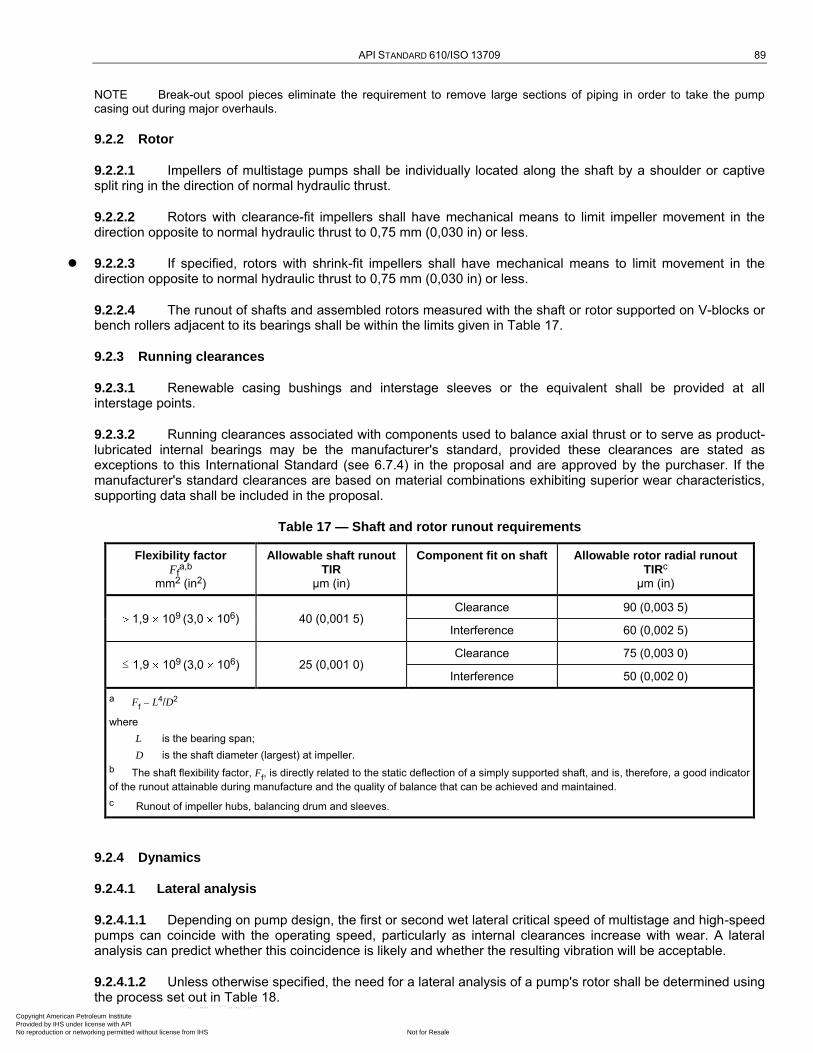
API STANDARD 610/ISO 13709 89
NOTE Break-out spool pieces eliminate the requirement to remove large sections of piping in order to take the pump casing out during major overhauls.
9.2.2 Rotor
9.2.2.1 Impellers of multistage pumps shall be individually located along the shaft by a shoulder or captive split ring in the direction of normal hydraulic thrust.
9.2.2.2 Rotors with clearance-fit impellers shall have mechanical means to limit impeller movement in the direction opposite to normal hydraulic thrust to 0,75 mm (0,030 in) or less.
9.2.2.3 If specified, rotors with shrink-fit impellers shall have mechanical means to limit movement in the direction opposite to normal hydraulic thrust to 0,75 mm (0,030 in) or less.
9.2.2.4 The runout of shafts and assembled rotors measured with the shaft or rotor supported on V-blocks or bench rollers adjacent to its bearings shall be within the limits given in Table 17.
9.2.3 Running clearances
9.2.3.1 Renewable casing bushings and interstage sleeves or the equivalent shall be provided at all interstage points.
9.2.3.2 Running clearances associated with components used to balance axial thrust or to serve as product-lubricated internal bearings may be the manufacturer's standard, provided these clearances are stated as exceptions to this International Standard (see 6.7.4) in the proposal and are approved by the purchaser. If the manufacturer's standard clearances are based on material combinations exhibiting superior wear characteristics, supporting data shall be included in the proposal.
Table 17 — Shaft and rotor runout requirements
Flexibility factor Ff
a,b mm2 (in2)
Allowable shaft runout TIR
µm (in)
Component fit on shaft Allowable rotor radial runout TIRc
µm (in)
1,9 109 (3,0 106) 40 (0,001 5)
Clearance 90 (0,003 5)
Interference 60 (0,002 5)
≤ 1,9 109 (3,0 106) 25 (0,001 0)
Clearance 75 (0,003 0)
Interference 50 (0,002 0)
a Ff L4/D2
where
L is the bearing span;
D is the shaft diameter (largest) at impeller.
b The shaft flexibility factor, Ff, is directly related to the static deflection of a simply supported shaft, and is, therefore, a good indicator
of the runout attainable during manufacture and the quality of balance that can be achieved and maintained.
c Runout of impeller hubs, balancing drum and sleeves.
9.2.4 Dynamics
9.2.4.1 Lateral analysis
9.2.4.1.1 Depending on pump design, the first or second wet lateral critical speed of multistage and high-speed pumps can coincide with the operating speed, particularly as internal clearances increase with wear. A lateral analysis can predict whether this coincidence is likely and whether the resulting vibration will be acceptable.
9.2.4.1.2 Unless otherwise specified, the need for a lateral analysis of a pump's rotor shall be determined using the process set out in Table 18.
Copyright American Petroleum Institute Provided by IHS under license with API
Not for ResaleNo reproduction or networking permitted without license from IHS
--`,,```,,,,````-`-`,,`,,`,`,,`---
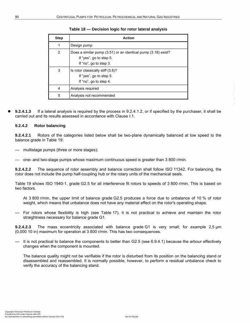
90 CENTRIFUGAL PUMPS FOR PETROLEUM, PETROCHEMICAL AND NATURAL GAS INDUSTRIES
Table 18 — Decision logic for rotor lateral analysis
Step Action
1 Design pump
2 Does a similar pump (3.51) or an identical pump (3.18) exist?
If ―yes‖, go to step 5.
If ―no‖, go to step 3.
3 Is rotor classically stiff (3.8)?
If ―yes‖, go to step 5.
If ―no‖, go to step 4.
4 Analysis required
5 Analysis not recommended
9.2.4.1.3 If a lateral analysis is required by the process in 9.2.4.1.2, or if specified by the purchaser, it shall be carried out and its results assessed in accordance with Clause I.1.
9.2.4.2 Rotor balancing
9.2.4.2.1 Rotors of the categories listed below shall be two-plane dynamically balanced at low speed to the balance grade in Table 19:
multistage pumps (three or more stages);
one- and two-stage pumps whose maximum continuous speed is greater than 3 800 r/min.
9.2.4.2.2 The sequence of rotor assembly and balance correction shall follow ISO 11342. For balancing, the rotor does not include the pump half-coupling hub or the rotary units of the mechanical seals.
Table 19 shows ISO 1940-1, grade G2.5 for all interference fit rotors to speeds of 3 800 r/min. This is based on two factors.
At 3 800 r/min, the upper limit of balance grade G2.5 produces a force due to unbalance of 10 % of rotor weight, which means that unbalance does not have any material effect on the rotor's operating shape.
For rotors whose flexibility is high (see Table 17), it is not practical to achieve and maintain the rotor straightness necessary for balance grade G1.
9.2.4.2.3 The mass eccentricity associated with balance grade G1 is very small; for example 2,5 µm (0,000 10 in) maximum for operation at 3 800 r/min. This has two consequences.
It is not practical to balance the components to better than G2.5 (see 6.9.4.1) because the arbour effectively changes when the component is mounted.
The balance quality might not be verifiable if the rotor is disturbed from its position on the balancing stand or disassembled and reassembled. It is normally possible, however, to perform a residual unbalance check to verify the accuracy of the balancing stand.
Copyright American Petroleum Institute Provided by IHS under license with API
Not for ResaleNo reproduction or networking permitted without license from IHS
--`,,```,,,,````-`-`,,`,,`,`,,`---
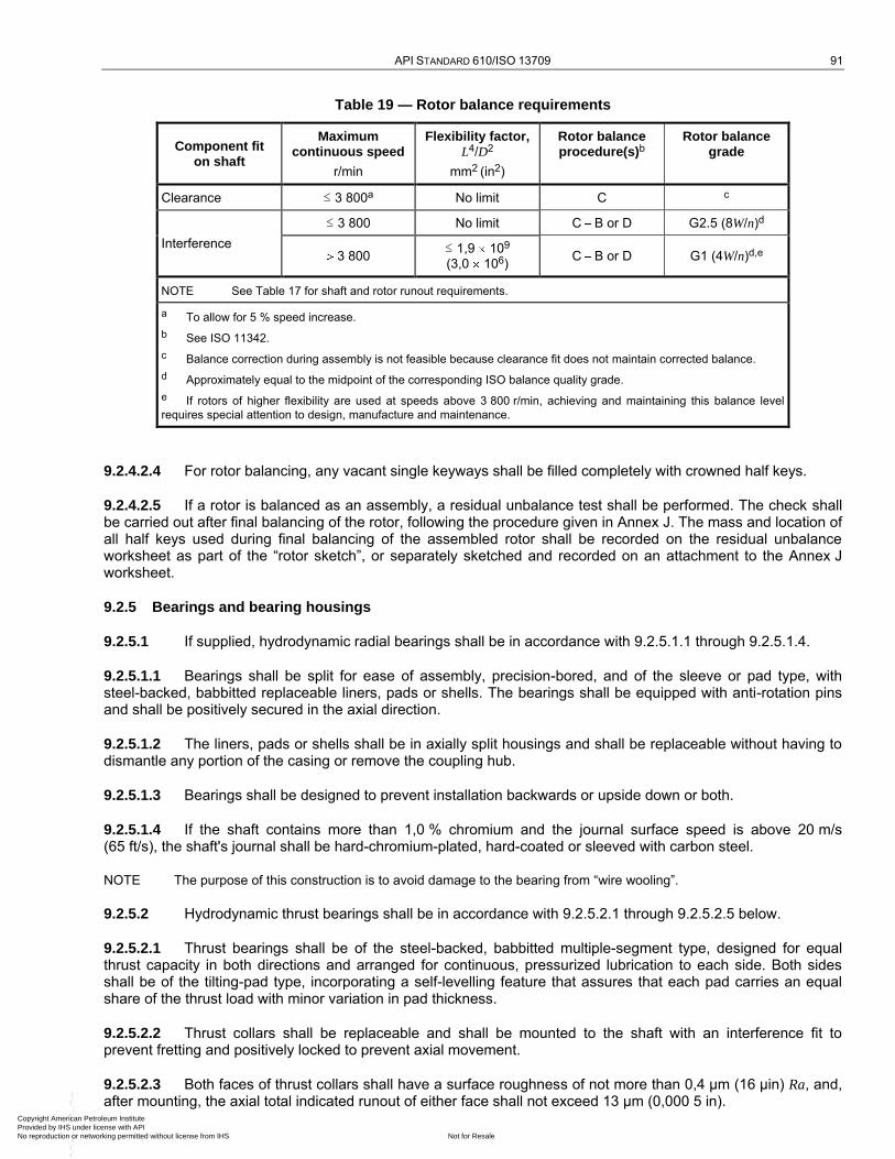
API STANDARD 610/ISO 13709 91
Table 19 — Rotor balance requirements
Component fit on shaft
Maximum continuous speed
r/min
Flexibility factor, L4/D2
mm2 (in2)
Rotor balance procedure(s)b
Rotor balance grade
Clearance ≤ 3 800a No limit C c
Interference
≤ 3 800 No limit C B or D G2.5 (8W/n)d
3 800 ≤ 1,9 109
(3,0 106) C B or D G1 (4W/n)d,e
NOTE See Table 17 for shaft and rotor runout requirements.
a To allow for 5 % speed increase.
b See ISO 11342.
c Balance correction during assembly is not feasible because clearance fit does not maintain corrected balance.
d Approximately equal to the midpoint of the corresponding ISO balance quality grade.
e If rotors of higher flexibility are used at speeds above 3 800 r/min, achieving and maintaining this balance level
requires special attention to design, manufacture and maintenance.
9.2.4.2.4 For rotor balancing, any vacant single keyways shall be filled completely with crowned half keys.
9.2.4.2.5 If a rotor is balanced as an assembly, a residual unbalance test shall be performed. The check shall be carried out after final balancing of the rotor, following the procedure given in Annex J. The mass and location of all half keys used during final balancing of the assembled rotor shall be recorded on the residual unbalance worksheet as part of the ―rotor sketch‖, or separately sketched and recorded on an attachment to the Annex J worksheet.
9.2.5 Bearings and bearing housings
9.2.5.1 If supplied, hydrodynamic radial bearings shall be in accordance with 9.2.5.1.1 through 9.2.5.1.4.
9.2.5.1.1 Bearings shall be split for ease of assembly, precision-bored, and of the sleeve or pad type, with steel-backed, babbitted replaceable liners, pads or shells. The bearings shall be equipped with anti-rotation pins and shall be positively secured in the axial direction.
9.2.5.1.2 The liners, pads or shells shall be in axially split housings and shall be replaceable without having to dismantle any portion of the casing or remove the coupling hub.
9.2.5.1.3 Bearings shall be designed to prevent installation backwards or upside down or both.
9.2.5.1.4 If the shaft contains more than 1,0 % chromium and the journal surface speed is above 20 m/s (65 ft/s), the shaft's journal shall be hard-chromium-plated, hard-coated or sleeved with carbon steel.
NOTE The purpose of this construction is to avoid damage to the bearing from ―wire wooling‖.
9.2.5.2 Hydrodynamic thrust bearings shall be in accordance with 9.2.5.2.1 through 9.2.5.2.5 below.
9.2.5.2.1 Thrust bearings shall be of the steel-backed, babbitted multiple-segment type, designed for equal thrust capacity in both directions and arranged for continuous, pressurized lubrication to each side. Both sides shall be of the tilting-pad type, incorporating a self-levelling feature that assures that each pad carries an equal share of the thrust load with minor variation in pad thickness.
9.2.5.2.2 Thrust collars shall be replaceable and shall be mounted to the shaft with an interference fit to prevent fretting and positively locked to prevent axial movement.
9.2.5.2.3 Both faces of thrust collars shall have a surface roughness of not more than 0,4 µm (16 µin) Ra, and, after mounting, the axial total indicated runout of either face shall not exceed 13 µm (0,000 5 in).
Copyright American Petroleum Institute Provided by IHS under license with API
Not for ResaleNo reproduction or networking permitted without license from IHS
--`,,```,,,,````-`-`,,`,,`,`,,`---
92 CENTRIFUGAL PUMPS FOR PETROLEUM, PETROCHEMICAL AND NATURAL GAS INDUSTRIES
9.2.5.2.4 Thrust bearings shall be sized for the maximum, continuous, applied load (see 6.10.1.2). At this load, and the corresponding rotative speed, the following parameters shall be met:
a) minimum oil-film thickness of 8 µm (0,000 3 in);
b) maximum unit pressure (load divided by area) of 3 500 kPa (35 bar; 500 psi);
c) maximum calculated babbitt surface temperature of 130 °C (265 °F).
If specified, thrust-bearing sizing shall be reviewed and approved by the purchaser.
The limits given above correspond to a design factor of two or more, based on the bearing's ultimate capacity. The calculated babbitt surface temperature is a design value and is not representative of actual babbitt temperatures under these conditions. Bearings sized to meet the above criteria have the following allowable metal temperatures on shop test and in the field (see 6.10.2.4):
shop test on water and normal operation in the field [see 8.3.3.5 c)]: 93 °C (200 °F);
field alarm or trip: 115 °C (240 °F).
9.2.5.2.5 Thrust bearings shall be arranged to allow axial positioning of each rotor relative to the casing and the setting of the bearing's clearance or preload.
9.2.5.3 If the inlet oil temperature exceeds 50 °C (120 °F), special consideration shall be given to bearing design, oil flow and allowable temperature rise. Oil outlets from thrust bearings shall be as recommended by the bearing manufacturer for the collar speed and lubrication method involved. Oil connections on bearing housings shall be in accordance with 7.5.
9.2.5.4 Axially split bearing housings shall have a metal-to-metal split joint whose halves are located by means of cylindrical dowels.
9.2.6 Lubrication
9.2.6.1 If specified, or if recommended by the vendor and approved by the purchaser, a pressure-lubrication system shall be furnished to supply oil at a suitable pressure to the pump bearings, the driver and any other driven equipment, including gears.
9.2.6.2 External pressure-lubrication systems shall comply with the requirements of ISO 10438-3. Figure B.8 and Table B.1 show details of the minimum acceptable system for equipment furnished to this International Standard.
9.2.6.3 If oil is supplied from a common system to two or more machines (such as a pump, a gear and a motor), the oil's characteristics shall be suitable for all equipment supplied. The vendor having unit responsibility shall obtain approval from the purchaser and the other equipment vendors for the oil selection.
NOTE The typical lubricants employed in a common oil system are mineral (hydrocarbon) oils that correspond to ISO Grades 32 through 68, as specified in ISO 3448.
9.2.6.4 If specified, the pressure-lubrication system shall conform to the requirements of ISO 10438-2. For such a lubrication system, data sheets should be supplied.
9.2.7 Testing
9.2.7.1 For pressure-lubricated bearings, test stand oil and oil system components downstream of the filters shall meet the cleanliness requirements specified in ISO 10438-3.
9.2.7.2 During the shop test of pumps with pressure-lubricated bearings, the oil flowrate to each bearing housing shall be measured and recorded.
Copyright American Petroleum Institute Provided by IHS under license with API
Not for ResaleNo reproduction or networking permitted without license from IHS
--`,,```,,,,````-`-`,,`,,`,`,,`---
API STANDARD 610/ISO 13709 93
9.2.7.3 All purchased vibration probes, transducers and oscillator-demodulators shall be in use during the test. If vibration probes are not furnished by the vendor or if the purchased probes are not compatible with shop readout facilities, shop probes and readouts that meet the accuracy requirements of ANSI/API Std 670 shall be used. The vibration measured with this instrumentation shall be the basis for acceptance or rejection of the pump (see 6.9.3.6).
9.2.7.4 With the purchaser's approval, single-stage, double-suction pumps may be assembled for testing by driving from the opposite end of the pump when compared to the general arrangement for the contract pump and driver. No retest is required after final assembly. If such an arrangement is required, it shall be stated in the proposal.
NOTE This is sometimes required to accommodate test stand piping constraints.
9.2.7.5 If specified, hydrodynamic bearings shall be removed, inspected by the purchaser or his representative, and reassembled after the performance test is completed.
9.2.8 Preparation for shipment
9.2.8.1 If a spare rotor or element is purchased, it shall be prepared for unheated indoor storage for three years. Storage preparation shall include treatment with a rust preventive and enclosure in a vapour-barrier envelope with slow-release vapour-phase inhibitor. The rotor or element shall be boxed for the type of shipment specified. A rotor shall have a resilient material (but not lead, TFE or PTFE), at least 3 mm (0,12 in) thick, between the rotor and its support cradle; support shall not be at the rotor's journals. An element shall have its rotor secured to prevent movement within the stator.
9.2.8.2 If specified, spare rotors and cartridge-type elements shall be prepared for vertical storage. A rotor shall be supported from its coupling end with a fixture designed to support 1,5 times the rotor's mass without damaging the shaft. A cartridge-type element shall be supported from the casing cover (with the rotor hanging from its thrust bearing).
9.2.8.3 If specified, a shipping and storage container designed to store the rotor or cartridge vertically shall be provided.
9.2.8.4 If specified, the shipping and storage container shall be designed to allow inert-gas inhibition during storage.
9.3 Vertically suspended pumps (types VS1 through VS7)
9.3.1 General
9.3.1.1 Specified discharge pressure shall be at the purchaser discharge connection. Hydraulic performance shall be corrected for column static and friction head losses. Bowl or pump casing performance curves shall be furnished with the correction indicated.
9.3.1.2 It is not necessary that bearing housings for vertically suspended pumps be arranged so that bearings can be replaced without disturbing pump drives or mountings.
9.3.2 Pressure casings
9.3.2.1 Jackscrews and casing alignment dowels are not required for rabbeted bowl assemblies.
9.3.2.2 Pumps shall be provided with vent connections for suction barrels and seal chambers.
9.3.2.3 Assemblies designed for O-ring seals only do not require flanges and bolting designed to seat a spiral-wound gasket (see 6.3.10).
Copyright American Petroleum Institute Provided by IHS under license with API
Not for ResaleNo reproduction or networking permitted without license from IHS
--`,,```,,,,````-`-`,,`,,`,`,,`---
94 CENTRIFUGAL PUMPS FOR PETROLEUM, PETROCHEMICAL AND NATURAL GAS INDUSTRIES
9.3.3 Rotors
9.3.3.1 All pump shafts shall be machined or ground and finished throughout their entire length. The total indicated runout shall not exceed 40 µm/m (0,000 5 in/ft) of length. Total runout shall not exceed 80 µm (0,003 in) over total shaft length.
For pumps with a shaft length over 4 500 mm (177 in), the vendor may propose an alternative total indicated runout [over 80 µm (0,003 in)] limit to the purchaser for approval.
9.3.3.2 The pump shaft shall be in one piece unless otherwise approved by the purchaser (because of total shaft length or shipping restrictions).
9.3.4 Wear parts and running clearances
9.3.4.1 Renewable casing bushings shall be provided at all interstage and other bushing locations. However, the interstage pressure differential and the character of the liquid handled (for example, dirty or non-lubricating) should determine the need for corresponding shaft sleeves.
9.3.4.2 The running clearances specified in 6.7.4 do not apply to the clearances of bushings. The clearances used shall be stated in the proposal and approved by the purchaser.
9.3.4.3 Pumps with semi-open impellers in an erosive service shall have a replaceable casing liner.
9.3.5 Dynamics
If specified, the vendor shall furnish a dynamic analysis of the pump and its support structure to confirm acceptability of the design. The purchaser and the vendor shall agree on the extent, method and acceptance criteria for this analysis.
Vertically suspended pumps are generally flexible structures with running speeds located between natural frequencies. As such, they are susceptible to resonant vibration if their separation margins are not verified during design. The basic structural elements typically include the foundation, pump structures and motor frames. Typically, the deflection of the foundation represents less than 5 % of the total deflection of the structural elements. If foundation data are not available when the analysis is being conducted, an agreed-upon value should be used. Generally, a 20 % margin of separation should be maintained between the natural frequency of the motor support structure and the operating speed.
9.3.6 Bushings and bearings
9.3.6.1 Bushings shall be suitably corrosion-resistant and abrasion-resistant for the specified product and temperature. The maximum spacing between shaft bushings shall be in accordance with Figure 37 in order to maintain the first critical speed above the maximum allowable continuous speed.
9.3.6.2 Thrust bearings that are integral with the driver shall meet the requirements of 7.1.8. Thrust bearings and housings integral with the pump shall meet the applicable requirements of 6.10. To allow axial rotor adjustment and oil lubrication, the thrust bearing shall be mounted with an interference fit on a slide-fit, key-driven sleeve.
9.3.6.3 Except for sump pumps of type VS4, the first-stage impeller shall be located between bushings.
NOTE Although between-bushing first-stage impellers can result in superior rotor support, certain applications, such as for sumps, require superior suction performance and can benefit from an overhung first-stage impeller arrangement.
9.3.7 Lubrication
Bushings in vertical pumps are normally lubricated by the liquid pumped. Alternative methods of lubrication shall be proposed if the pumped liquid is not suitable.
Copyright American Petroleum Institute Provided by IHS under license with API
Not for ResaleNo reproduction or networking permitted without license from IHS
--`,,```,,,,````-`-`,,`,,`,`,,`---
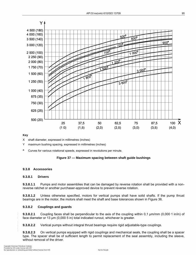
API STANDARD 610/ISO 13709 95
Key
X shaft diameter, expressed in millimetres (inches)
Y maximum bushing spacing, expressed in millimetres (inches)
a Curves for various rotational speeds, expressed in revolutions per minute.
Figure 37 — Maximum spacing between shaft guide bushings
9.3.8 Accessories
9.3.8.1 Drivers
9.3.8.1.1 Pumps and motor assemblies that can be damaged by reverse rotation shall be provided with a non-reverse ratchet or another purchaser-approved device to prevent reverse rotation.
9.3.8.1.2 Unless otherwise specified, motors for vertical pumps shall have solid shafts. If the pump thrust bearings are in the motor, the motors shall meet the shaft and base tolerances shown in Figure 36.
9.3.8.2 Couplings and guards
9.3.8.2.1 Coupling faces shall be perpendicular to the axis of the coupling within 0,1 µm/mm (0,000 1 in/in) of face diameter or 13 µm (0,000 5 in) total indicated runout, whichever is greater.
9.3.8.2.2 Vertical pumps without integral thrust bearings require rigid adjustable-type couplings.
9.3.8.2.3 On vertical pumps equipped with rigid couplings and mechanical seals, the coupling shall be a spacer type. The spacer shall be of sufficient length to permit replacement of the seal assembly, including the sleeve, without removal of the driver.
Copyright American Petroleum Institute Provided by IHS under license with API
Not for ResaleNo reproduction or networking permitted without license from IHS
--`,,```,,,,````-`-`,,`,,`,`,,`---
96 CENTRIFUGAL PUMPS FOR PETROLEUM, PETROCHEMICAL AND NATURAL GAS INDUSTRIES
9.3.8.3 Mounting plates
9.3.8.3.1 If specified, the mounting plate for double-casing pumps shall be separate from the main body flange and located sufficiently below it to permit the use of through-bolting on the body flange (see Figure 38).This results in a higher joint integrity and should be considered for critical and cryogenic services.
9.3.8.3.2 A minimum of four alignment-positioning screws shall be provided for each drive-train component that has a mass greater than 250 kg (500 lb) to facilitate horizontal adjustment.
9.3.8.3.3 If specified, pumps shall be provided with a separate sole plate for bolting and grouting to the foundation (see Figure 38). This plate shall be machined on its top surface for mounting of the discharge head, can or motor support.
9.3.8.3.4 The outside corners of the sole plate or mounting plate imbedded in the grout shall have at least 50 mm (2 in) radii in the plan view (see Figure D.1).
9.3.8.4 Piping and appurtenances
If mechanical seals and drivers are not installed prior to shipment, the seal piping system shall not be fully assembled.
9.3.9 Testing
9.3.9.1 Pumps shall be tested as complete assemblies. Tests using only bowls and impellers are not recommended. In cases where assembled-unit testing is impractical, the vendor shall submit alternative testing procedures with the proposal. Suction cans, if supplied, are not required for performance testing.
9.3.9.2 If specified, a resonance test with the pump unpiped shall be conducted on the pump structure/driver frame assembly. The test shall be performed as follows.
Excite the assembly by making an impact on the driver frame in the direction of the discharge flange.
Determine the natural frequencies by the response.
Excite the assembly by making an impact on the driver frame at 90° to the direction of the discharge flange.
Determine the natural frequencies by the response.
The natural frequencies so determined shall be at least 10 % below the minimum continuous operating speed or shall be at least 10 % above the maximum continuous operating speed.
9.3.10 Single-case diffuser (VS1) and volute (VS2) pumps
9.3.10.1 The components that constitute the pressure casing are the casing (bowls), column and discharge head.
NOTE It is not necessary that bowls on VS1 pumps in S-6 materials be 12 % chrome; they can be carbon steel.
9.3.10.2 Line shafts may be open or enclosed. For enclosed line shafts, the type of lubrication shall be approved by the purchaser.
Open line-shafting is lubricated by the pumped liquid. If the pumped liquid is not suitable as a lubricant, enclosed line-shafting may be provided to ensure a clean lubrication supply for line-shaft bearings.
9.3.10.3 The discharge-head mounting surface shall be suitable for both grouting and mounting on a machined sole plate.
9.3.10.4 Thrust restraints are required at the pump if an expansion joint is installed on the discharge nozzle. Design review of the proposed installation and piping by the vendor is recommended.
9.3.10.5 If specified, line shafting shall be furnished with hardened sleeves under each bushing. Copyright American Petroleum Institute Provided by IHS under license with API
Not for ResaleNo reproduction or networking permitted without license from IHS
--`,,```,,,,````-`-`,,`,,`,`,,`---

API STANDARD 610/ISO 13709 97
9.3.10.6 Unless otherwise specified, integral bushing spiders and rabbeted fits shall be used for all column sizes.
9.3.10.7 Unless otherwise specified, bowls shall be flanged and shall have metal-to-metal rabbeted fits.
Key
1 suction flange 7 main body flange through-bolting (typical)
2 main body flange 8 hold-down bolts (typical)
3 mounting flange 9 anchor bolts (typical)
4 sole plate 10 grout
5 pump head 11 can (outer casing)
6 discharge flange
Figure 38 — Typical mounting for vertically suspended, double-case pumps (VS6 and VS7) with sole plate
9.3.11 Single-casing axial flow (VS3) pumps
9.3.11.1 The components that constitute the pressure casing are the casing (bowl), column and discharge head.
9.3.11.2 Unless otherwise specified, integral bushing spiders and rabbeted fits shall be used for all column sizes.
9.3.11.3 Bowls shall have metal-to-metal rabbeted fits.
9.3.12 Single-casing line shaft (VS4) and cantilever (VS5) pumps
9.3.12.1 For VS4 pumps, bushings shall be provided to support the shaft and impeller.
9.3.12.2 VS5 pumps shall comply with a) through d) as follows.
a) The rotor shall be cantilevered from its bearing assembly. Submerged bottom bushings are not used to guide the shaft.
Copyright American Petroleum Institute Provided by IHS under license with API
Not for ResaleNo reproduction or networking permitted without license from IHS
--`,,```,,,,````-`-`,,`,,`,`,,`---

98 CENTRIFUGAL PUMPS FOR PETROLEUM, PETROCHEMICAL AND NATURAL GAS INDUSTRIES
b) The shaft stiffness shall limit total deflection, without the use of a casing bushing, such that the impeller does not contact the pump casing under the most severe dynamic conditions over the complete head-flow curve with a maximum diameter impeller and at the maximum speed and liquid density.
c) Cantilever type pumps shall have their first dry critical speed, for their rotors, 30 % above their maximum allowable continuous speed.
d) For cantilever-type VS5 pumps, the shaft total indicated runout shall not exceed 50 µm (0,002 in) as measured on the shaft directly above the mechanical seal or stuffing box.
9.3.12.3 For open-system sump-pump service, the pressure-containing components of the type VS4 and type VS5 pumps are the casing, suction cover and discharge line. For closed-system pressurized or vacuum tank service, the seal chamber, pump cover plate and tank cover also become pressure-containing components.
9.3.12.4 For VS4 pumps, the thrust bearing shall be designed for either grease or oil-mist lubrication. Bushings may be lubricated with water, grease or product, or be self-lubricated. Type VS5 pump bearings shall be grease-lubricated. The stabilized bearing housing temperature shall not exceed 82 °C (180 °F) when operating at an ambient temperature of 43 °C (110 °F). Recommended greases shall be suitable for operation at these temperatures.
9.3.12.5 Mechanical seals are typically not supplied on VS4 and VS5 pumps unless required for closed-system service.
9.3.12.6 Lifting lugs shall be provided in the cover plate for lifting the pump assembly, including the driver.
9.3.12.7 The discharge nozzle and cover plate shall be designed as required in 6.3.3.
If the pump is mounted in a vessel, the pump-mounting nozzle of the vessel should also be designed to withstand the allowable nozzle loads. See 6.5 for allowable nozzle loads.
9.3.12.8 Cover-plate joints shall be vapour-tight for closed-system services. The cover-plate design and mounting shall be agreed to by the purchaser and vendor.
9.3.12.9 Mechanical seals, if supplied, shall be located at the cover plate to seal the vapour in the supply tank or vessel. Mechanical seals normally seal vapour; however, they shall be designed to operate in liquid in the event of tank or vessel overfilling. The seal chamber shall have provisions for a high-point vent.
9.3.12.10 Pump-out vanes may be used in lieu of wear rings to reduce leakage back to the sump.
9.3.12.11 Typically, spacer couplings are not used on VS4 and VS5 type pumps. Coupling hubs shall be supplied with slip fits to the shaft. The coupling hubs and keys shall be secured to the shaft with set-screws to facilitate final coupling adjustment.
9.3.13 Double-casing diffuser (VS6) and volute (VS7) pumps
9.3.13.1 The components that constitute the pressure casing of type VS6 pumps are the discharge head and the suction can. The components that constitute the pressure casing of type VS7 pumps are the outer casing (complete with the discharge nozzle), the head plate and the suction pipe.
9.3.13.2 If specified, bowls and column pipe shall be hydrostatically tested with liquid at a minimum of 1,5 times the maximum differential pressure developed by the bowl assembly. Hydrostatic testing shall be conducted in accordance with the requirements of 8.3.2.
9.3.13.3 Complete outer-case venting shall be ensured by means of a high-point vent connection.
9.3.13.4 Provision shall be made to ensure complete venting of the inner assembly within the seal chamber or associated auxiliary process piping.
9.3.13.5 If specified, the suction can shall be supplied with a drain piped to the surface.
9.3.13.6 Column sections shall incorporate integral bushing spiders and rabbeted fits for all column sizes. Copyright American Petroleum Institute Provided by IHS under license with API
Not for ResaleNo reproduction or networking permitted without license from IHS
--`,,```,,,,````-`-`,,`,,`,`,,`---
API STANDARD 610/ISO 13709 99
10 Vendor's data
10.1 General
10.1.1 The vendor shall furnish the information specified in 10.2 and 10.3.
10.1.2 The vendor's data shall be present on transmittal (cover) letters, title pages and in title blocks or other prominent position on drawings, and shall include the following information:
a) purchaser's/owner's corporate name;
b) job/project number;
c) equipment item number and service name;
d) inquiry or purchaser-order number;
e) any other identification specified in the inquiry or purchaser order;
f) vendor's identifying proposal number, shop order number, serial number, or other reference required to completely identify return correspondence.
10.1.3 If specified, a coordination meeting shall be held, preferably at the vendor's plant, within four to six weeks after order commitment. Unless otherwise specified, the vendor shall prepare and distribute an agenda prior to this meeting, which as a minimum, shall include a review of the following items:
a) purchase order, scope of supply, unit responsibility, and sub-vendor items;
b) data sheets;
c) applicable specifications and previously agreed-upon exceptions;
d) schedules for transmittal of data, production and testing;
e) quality assurance programme and procedures;
f) inspection, expediting and testing;
g) schematics and bills of material for auxiliary systems;
h) physical orientation of the equipment, piping and auxiliary systems;
i) coupling selection and rating;
j) thrust and journal bearing sizing, estimated loadings and specific configurations;
k) rotor dynamic analyses (lateral, torsional and transient torsional, as required; commonly not available for 10 weeks to 12 weeks);
l) equipment performance, alternative operating conditions, start-up, shutdown and any operating limitations;
m) scope and details of any pulsation or vibration analysis;
n) instrumentation and controls;
o) identification of items for stress analysis or other design reviews;
p) other technical items.
Copyright American Petroleum Institute Provided by IHS under license with API
Not for ResaleNo reproduction or networking permitted without license from IHS
--`,,```,,,,````-`-`,,`,,`,`,,`---
100 CENTRIFUGAL PUMPS FOR PETROLEUM, PETROCHEMICAL AND NATURAL GAS INDUSTRIES
10.2 Proposals
10.2.1 General
10.2.1.1 The vendor shall forward the original proposal and the specified number of copies to the addressee specified in the inquiry documents. As a minimum, the proposal shall include the data specified in 10.2.2 through 10.2.5, as well as a specific statement that the system and all its components are in strict accordance with this International Standard. If the system and components are not in strict accordance, the vendor shall include a list that details and explains each deviation. The vendor shall provide details to enable the purchaser to evaluate any proposed alternative designs. All correspondence shall be clearly identified in accordance with 10.1.2.
10.2.1.2 Clearances less than those required by Table 6 shall be stated as an exception to this International Standard in the proposal.
10.2.2 Drawings
10.2.2.1 The drawings indicated on the Vendor drawing and data requirements (VDDR) form (see example in Annex L) shall be included in the proposal. As a minimum, the following data shall be furnished:
a) general arrangement or outline drawing for each major skid or system, showing direction of rotation, size and location of major purchaser connections; overall dimensions; maintenance clearance dimensions; overall masses; erection masses; maximum maintenance masses (indicated for each piece), lifting points and methods of lifting the assembled machine and, if applicable, the standard baseplate number (see Annex D);
b) cross-sectional drawings showing the details of the proposed equipment;
c) schematics of all auxiliary systems, including the seal flush, lubricating oil, control and electrical systems. Bills of material shall be included.
10.2.2.2 If typical drawings, schematics and bills of material are used, they shall be marked up to show the correct mass and dimension data and to reflect the actual equipment and scope proposed.
10.2.3 Technical data
The following data shall be included in the proposal:
a) purchaser's data sheets, with complete vendor's information entered thereon and literature to fully describe details of the offering;
b) predicted noise data (6.1.14);
c) Vendor drawing and data requirements form (see example in Annex L), indicating the schedule according to which the vendor agrees to transmit all the data specified as part of the purchase order;
d) schedule for shipment of the equipment, in weeks after receipt of the order;
e) list of major wearing components, showing interchangeability with other items on the project or the owner's existing machines;
f) list of spare parts recommended for start-up and normal maintenance purposes (see Table 20);
g) list of the special tools furnished for maintenance (see 7.6.1);
h) description of any special weather protection and winterization required for start-up, operation and periods of idleness, under the site conditions specified on the data sheets; this description shall clearly indicate the protection being furnished by the purchaser as well as that included in the vendor's scope of supply;
i) complete tabulation of utility requirements, e.g. steam, water, electricity, air, gas, lubricating oil (including the quantity and supply pressure of the oil required, and the heat load being removed by the oil), and the nameplate power rating and operating power requirements of auxiliary drivers; approximate data shall be clearly indicated as such;
Copyright American Petroleum Institute Provided by IHS under license with API
Not for ResaleNo reproduction or networking permitted without license from IHS
--`,,```,,,,````-`-`,,`,,`,`,,`---
API STANDARD 610/ISO 13709 101
j) description of any optional or additional tests and inspection procedures for materials as required by 8.3.4 or 8.2.2;
k) description of any special requirements whether specified in the purchaser's inquiry or as outlined in 6.1.9, 6.1.10, 6.1.11, 6.3.4, 6.4.3.10, 6.4.3.12, 6.9.3.1, 6.12.1.1, 6.12.1.2, 6.12.1.3, 7.1.4, 7.1.8, 9.2.1.1, 9.2.3.2, 9.2.7.4, 9.3.4.2, 9.3.9.1, 10.2.1.2, 10.2.2.1, and 10.3.4.2;
l) if specified, a list of similar machines installed and operating under similar conditions;
m) any start-up, shutdown or operating restrictions required to protect the integrity of the equipment;
n) calculated specific speed;
o) any test facility limitations that can require the vendor to assemble and drive single-stage, double-suction pumps from the opposite end for testing (see 9.2.7.4);
p) list of any components that can be construed as being of alternative design, hence requiring purchaser's acceptance (6.2)
10.2.4 Curves
The vendor shall provide complete performance curves, including differential head, efficiency, water NPSH3, and power, expressed as functions of flowrate. Except for low specific-speed designs where it is not feasible, the curves shall be extended to at least 120 % of flowrate at peak efficiency, and the rated operating point shall be indicated. The head curve for maximum and minimum impeller diameters shall be included. The impeller identification number, specific speed and suction-specific speed shall be shown on the curves. If applicable, the curves shall indicate viscosity corrections. Minimum flow (both thermal and stable), preferred and allowable operating regions, and any limitations of operation shall be indicated.
10.2.5 Options
If specified, the vendor shall furnish an outline of the procedures used for each of the special or optional tests that have been specified by the purchaser or proposed by the vendor.
Copyright American Petroleum Institute Provided by IHS under license with API
Not for ResaleNo reproduction or networking permitted without license from IHS
--`,,```,,,,````-`-`,,`,,`,`,,`---
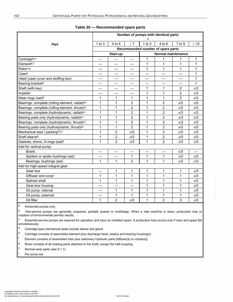
102 CENTRIFUGAL PUMPS FOR PETROLEUM, PETROCHEMICAL AND NATURAL GAS INDUSTRIES
Table 20 — Recommended spare parts
Part
Number of pumps with identical parts n
1 to 3 4 to 6 ≥ 7 1 to 3 4 to 6 7 to 9 ≥ 10
Recommended number of spare parts
Start-up Normal maintenance
Cartridgeb,e — — — 1 1 1 1
Elementb,f — — — 1 1 1 1
Rotorc,g — — — 1 1 1 1
Casea — — — — — — 1
Head (case cover and stuffing box) — — — — — — 1
Bearing bracketa — — — — — — 1
Shaft (with key) — — — 1 1 2 n/3
Impeller — — — 1 1 2 n/3
Wear rings (set)h 1 1 1 1 1 2 n/3
Bearings, complete (rolling element, radial)a,i 1 1 2 1 2 n/3 n/3
Bearings, complete (rolling element, thrust)a,i 1 1 2 1 2 n/3 n/3
Bearings, complete (hydrodynamic, radial)a,i 1 1 2 1 2 n/3 n/3
Bearing pads only (hydrodynamic, radial)a,i 1 1 2 1 2 n/3 n/3
Bearings, complete (hydrodynamic, thrust)a,i 1 1 2 1 2 n/3 n/3
Bearing pads only (hydrodynamic, thrust)a,i 1 1 2 1 2 n/3 n/3
Mechanical seal / packingd,h,i 1 2 n/3 1 2 n/3 n/3
Shaft sleeveh 1 2 n/3 1 2 n/3 n/3
Gaskets, shims, O-rings (set)h 1 2 n/3 1 2 n/3 n/3
Add for vertical pump:
Bowls — — — — — n/3 —
Spiders or spider bushings (set) — — 1 1 1 n/3 n/3
Bearings, bushings (set) 1 1 2 1 1 n/3 n/3
Add for high-speed integral gear:
Gear box — 1 1 1 1 1 n/3
Diffuser and cover 1 1 1 1 1 1 n/3
Splined shaft 1 1 1 1 1 1 n/3
Gear-box housing — — — 1 1 1 n/3
Oil pump, internal — 1 1 1 1 1 n/3
Oil pump, external — 1 1 1 1 1 n/3
Oil filter 1 2 n/3 1 2 3 n/3
a Horizontal pumps only.
b Vital-service pumps are generally unspared, partially spared or multistage. When a vital machine is down, production loss or
violation of environmental permits results.
c Essential-service pumps are required for operation and have an installed spare. A production loss occurs only if main and spare fail
simultaneously.
d Cartridge-type mechanical seals include sleeve and gland.
e Cartridge consists of assembled element plus discharge head, seal(s) and bearing housing(s).
f Element consists of assembled rotor plus stationary hydraulic parts [diffuser(s) or volute(s)].
g Rotor consists of all rotating parts attached to the shaft, except the half-coupling.
h Normal-wear parts (see 6.1.1).
i Per pump set.
Copyright American Petroleum Institute Provided by IHS under license with API
Not for ResaleNo reproduction or networking permitted without license from IHS
--`,,```,,,,````-`-`,,`,,`,`,,`---
API STANDARD 610/ISO 13709 103
10.3 Contract data
10.3.1 General
10.3.1.1 Contract data shall be furnished by the vendor in accordance with the agreed VDDR form (see example in Annex L).
10.3.1.2 Each drawing shall have a title block in the lower right-hand corner with the date of certification, vendor's data specified in 10.1.2, revision number and date and title. Similar information shall be provided on all other documents.
10.3.1.3 The purchaser and vendor shall agree to the timing and extent of drawing and data review. Review by the purchaser does not constitute permission to deviate from any requirements in the order unless specifically agreed upon in writing.
10.3.1.4 A complete list of vendor data shall be included with the first issue of the major drawings. This list shall contain titles, drawing numbers and a schedule for transmission of all the data the vendor is furnishing (see example in Annex L).
10.3.2 Drawings and technical data
10.3.2.1 The drawings and data furnished by the vendor shall contain sufficient information so that, together with the manuals specified in 10.3.5, the purchaser can properly install, operate and maintain the equipment covered by the purchase order. A completed ISO 13709 summary detailed in Annex N shall be included in the as-built data to document the pump. All contract drawings and data shall be clearly legible (8-point minimum font size even if reduced from a larger size drawing), shall cover the scope of the agreed VDDR form (see example in Annex L) and shall satisfy the applicable detailed descriptions.
Dimensional outline drawings shall indicate the tolerance for pump suction and discharge nozzle face and centreline locations referenced from the centreline of the nearest baseplate anchor-bolt hole. The centreline of baseplate anchor-bolt hole locations shall indicate the tolerance from a common reference point on the baseplate.
10.3.2.2 Certified test curves and data (see example in Annex M) shall be submitted within 15 days after testing and shall include head, power recalculated to the proper specific gravity and efficiency plotted against flowrate. If applicable, viscosity corrections shall be indicated. The water-NPSH3 curve shall be included, drawn from actual test data, for an impeller cast from the same pattern. The curve sheet shall include the maximum and minimum diameters of the impeller design supplied, the identification number of the impeller or impellers, and the pump serial number.
10.3.2.3 If specified, a generic casing drawing defining casing retirement thickness(es) in critical areas shall be provided. The retirement thickness(es) shall be based on failure to comply with any of the criteria in 6.3.3. and 6.3.4.
10.3.3 Progress reports
The vendor shall submit progress reports to the purchaser at the intervals specified on the VDDR form (see example in Annex L).
10.3.4 Parts lists and recommended spares
10.3.4.1 The vendor shall submit complete parts lists for all equipment and accessories supplied. The lists shall include manufacturer's unique part numbers, materials of construction and delivery times. Materials shall be identified as specified in 6.12.1. Each part shall be completely identified and shown on cross-sectional or assembly-type drawings so that the purchaser can determine the interchangeability of these parts with other equipment. Parts that have been modified from standard dimensions and/or finish to satisfy specific performance requirements shall be uniquely identified by part number for interchangeability and future duplication purposes. Standard purchased items, including gaskets and O-rings, shall be identified by the original manufacturer's name, part number, material and pressure rating, if applicable.
Copyright American Petroleum Institute Provided by IHS under license with API
Not for ResaleNo reproduction or networking permitted without license from IHS
--`,,```,,,,````-`-`,,`,,`,`,,`---
104 CENTRIFUGAL PUMPS FOR PETROLEUM, PETROCHEMICAL AND NATURAL GAS INDUSTRIES
10.3.4.2 The vendor shall indicate on each of these complete parts lists all those parts that are recommended as start-up or maintenance spares and the recommended stocking quantities of each. These should include spare parts recommendations of sub-suppliers that were not available for inclusion in the vendor's original proposal. The vendor shall forward the lists to the purchaser promptly after receipt of the reviewed drawings and in time to permit order and delivery of the parts before field start-up. The transmittal letter shall include the data specified in 10.1.2.
10.3.5 Data manuals
10.3.5.1 General
The vendor shall provide sufficient written instructions and all necessary drawings to enable the purchaser to install, operate and maintain all of the equipment covered by the purchase order. This information shall be compiled in a manual or manuals with a cover sheet showing the information listed in 10.1.2, an index sheet, and a complete list of the enclosed drawings by title and drawing number. The manual or manuals shall be prepared specifically for the equipment covered by the purchase order. Pre-printed sections that are model-specific may be included, but ―typical‖ manuals are unacceptable.
Vendor manuals shall also be furnished in an agreed-upon electronic format that reflect the ―as supplied‖ equipment, with any safeguards considered necessary for legal protection of all parties.
10.3.5.2 Installation manual
All information required for the proper installation of the equipment shall be compiled in a manual that shall be issued no later than the time of issue of final certified drawings. For this reason, it may be separate from the operating and maintenance instructions. This manual shall contain information on alignment and grouting procedures, normal and maximum utility requirements, centres of mass, rigging provisions and procedures, and all other installation data. All drawings and data specified in 10.2.2 and 10.2.3 that are pertinent to proper installation shall be included as part of this manual.
10.3.5.3 Manual for operating, maintenance and technical data
A manual containing operating, maintenance and technical data shall be sent at the time of shipment. In addition to covering operation at all specified process conditions, this manual shall include a section that provides special instructions for operation at specified extreme environmental conditions. The manual shall also include sketches that show the location of the centre of gravity and rigging provisions to permit the removal of the top half of the casings, rotors and any subassemblies having a mass greater than 135 kg (300 lb). As a minimum, the manual shall also include all of the data listed in Annex L that are not uniquely related to installation.
Copyright American Petroleum Institute Provided by IHS under license with API
Not for ResaleNo reproduction or networking permitted without license from IHS
--`,,```,,,,````-`-`,,`,,`,`,,`---
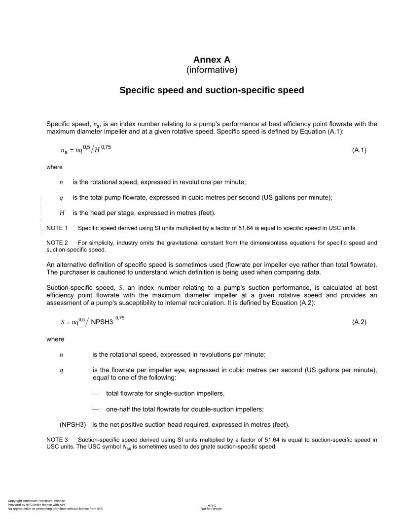
105
Annex A (informative)
Specific speed and suction-specific speed
Specific speed, ns, is an index number relating to a pump's performance at best efficiency point flowrate with the maximum diameter impeller and at a given rotative speed. Specific speed is defined by Equation (A.1):
n nq H0,5 0,75s (A.1)
where
n is the rotational speed, expressed in revolutions per minute;
q is the total pump flowrate, expressed in cubic metres per second (US gallons per minute);
H is the head per stage, expressed in metres (feet).
NOTE 1 Specific speed derived using SI units multiplied by a factor of 51,64 is equal to specific speed in USC units.
NOTE 2 For simplicity, industry omits the gravitational constant from the dimensionless equations for specific speed and suction-specific speed.
An alternative definition of specific speed is sometimes used (flowrate per impeller eye rather than total flowrate). The purchaser is cautioned to understand which definition is being used when comparing data.
Suction-specific speed, S, an index number relating to a pump's suction performance, is calculated at best efficiency point flowrate with the maximum diameter impeller at a given rotative speed and provides an assessment of a pump's susceptibility to internal recirculation. It is defined by Equation (A.2):
S nq0,750,5 NPSH3 (A.2)
where
n is the rotational speed, expressed in revolutions per minute;
q is the flowrate per impeller eye, expressed in cubic metres per second (US gallons per minute), equal to one of the following:
total flowrate for single-suction impellers,
one-half the total flowrate for double-suction impellers;
(NPSH3) is the net positive suction head required, expressed in metres (feet).
NOTE 3 Suction-specific speed derived using SI units multiplied by a factor of 51,64 is equal to suction-specific speed in USC units. The USC symbol Nss is sometimes used to designate suction-specific speed.
Copyright American Petroleum Institute Provided by IHS under license with API
Not for ResaleNo reproduction or networking permitted without license from IHS
--`,,```,,,,````-`-`,,`,,`,`,,`---
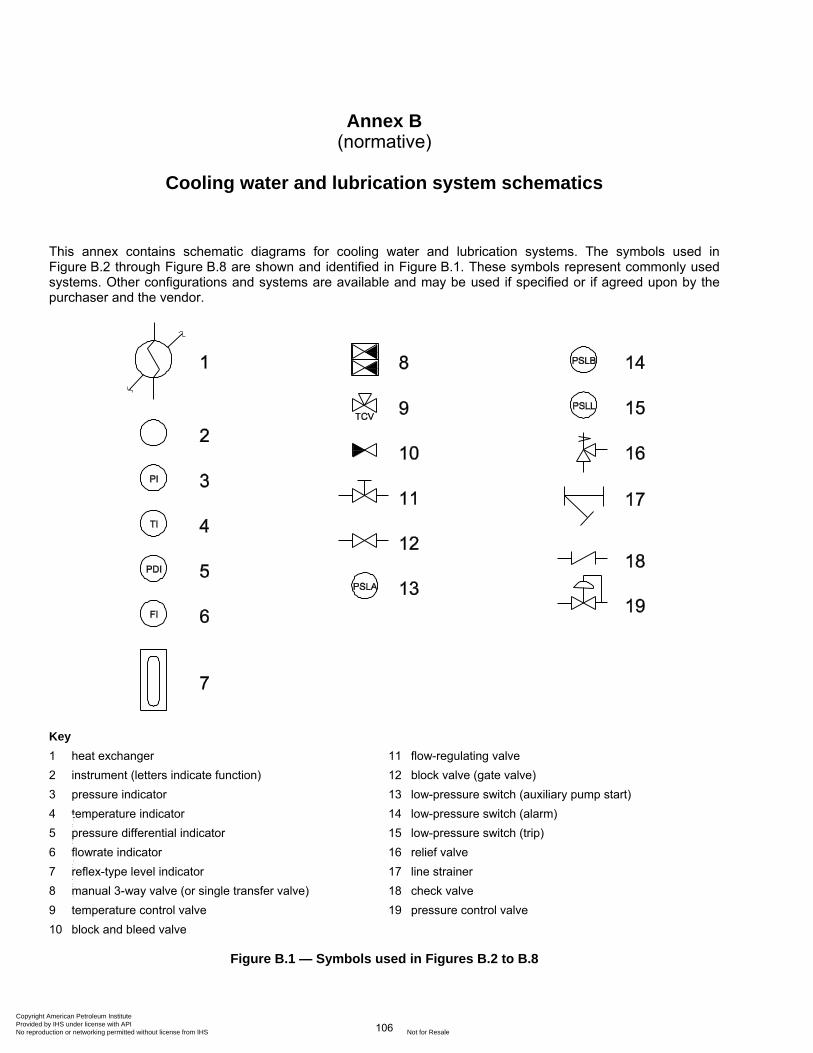
106
Annex B (normative)
Cooling water and lubrication system schematics
This annex contains schematic diagrams for cooling water and lubrication systems. The symbols used in Figure B.2 through Figure B.8 are shown and identified in Figure B.1. These symbols represent commonly used systems. Other configurations and systems are available and may be used if specified or if agreed upon by the purchaser and the vendor.
Key
1 heat exchanger 11 flow-regulating valve
2 instrument (letters indicate function) 12 block valve (gate valve)
3 pressure indicator 13 low-pressure switch (auxiliary pump start)
4 temperature indicator 14 low-pressure switch (alarm)
5 pressure differential indicator 15 low-pressure switch (trip)
6 flowrate indicator 16 relief valve
7 reflex-type level indicator 17 line strainer
8 manual 3-way valve (or single transfer valve) 18 check valve
9 temperature control valve 19 pressure control valve
10 block and bleed valve
Figure B.1 — Symbols used in Figures B.2 to B.8
Copyright American Petroleum Institute Provided by IHS under license with API
Not for ResaleNo reproduction or networking permitted without license from IHS
--`,,```,,,,````-`-`,,`,,`,`,,`---
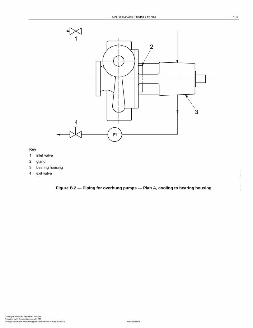
API STANDARD 610/ISO 13709 107
Key
1 inlet valve
2 gland
3 bearing housing
4 exit valve
Figure B.2 — Piping for overhung pumps — Plan A, cooling to bearing housing
Copyright American Petroleum Institute Provided by IHS under license with API
Not for ResaleNo reproduction or networking permitted without license from IHS
--`,,```,,,,````-`-`,,`,,`,`,,`---
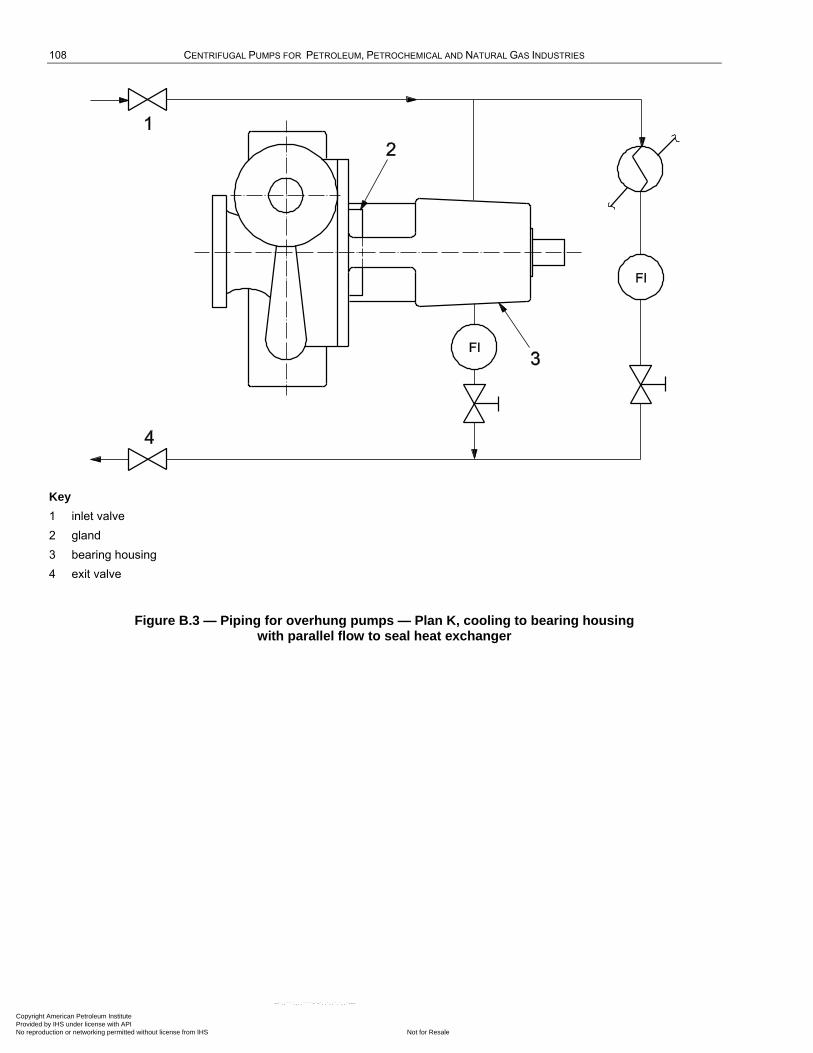
108 CENTRIFUGAL PUMPS FOR PETROLEUM, PETROCHEMICAL AND NATURAL GAS INDUSTRIES
Key
1 inlet valve
2 gland
3 bearing housing
4 exit valve
Figure B.3 — Piping for overhung pumps — Plan K, cooling to bearing housing with parallel flow to seal heat exchanger
Copyright American Petroleum Institute Provided by IHS under license with API
Not for ResaleNo reproduction or networking permitted without license from IHS
--`,,```,,,,````-`-`,,`,,`,`,,`---
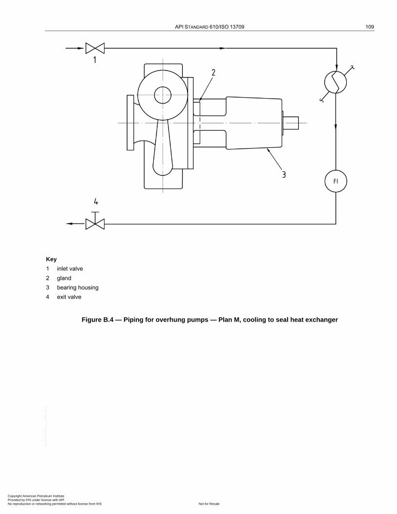
API STANDARD 610/ISO 13709 109
Key
1 inlet valve
2 gland
3 bearing housing
4 exit valve
Figure B.4 — Piping for overhung pumps — Plan M, cooling to seal heat exchanger
Copyright American Petroleum Institute Provided by IHS under license with API
Not for ResaleNo reproduction or networking permitted without license from IHS
--`,,```,,,,````-`-`,,`,,`,`,,`---
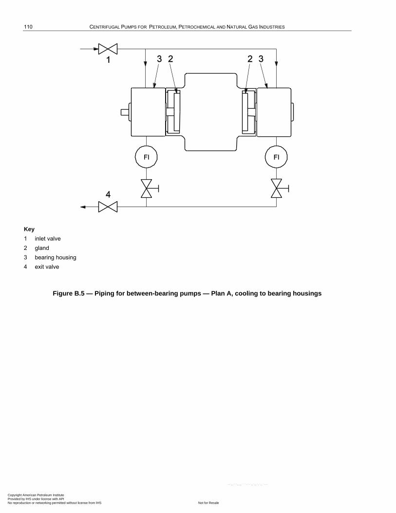
110 CENTRIFUGAL PUMPS FOR PETROLEUM, PETROCHEMICAL AND NATURAL GAS INDUSTRIES
Key
1 inlet valve
2 gland
3 bearing housing
4 exit valve
Figure B.5 — Piping for between-bearing pumps — Plan A, cooling to bearing housings
Copyright American Petroleum Institute Provided by IHS under license with API
Not for ResaleNo reproduction or networking permitted without license from IHS
--`,,```,,,,````-`-`,,`,,`,`,,`---
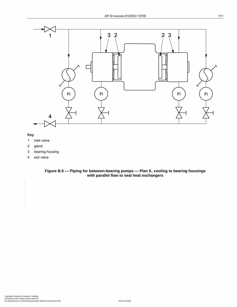
API STANDARD 610/ISO 13709 111
Key
1 inlet valve
2 gland
3 bearing housing
4 exit valve
Figure B.6 — Piping for between-bearing pumps — Plan K, cooling to bearing housings with parallel flow to seal heat exchangers
Copyright American Petroleum Institute Provided by IHS under license with API
Not for ResaleNo reproduction or networking permitted without license from IHS
--`,,```,,,,````-`-`,,`,,`,`,,`---
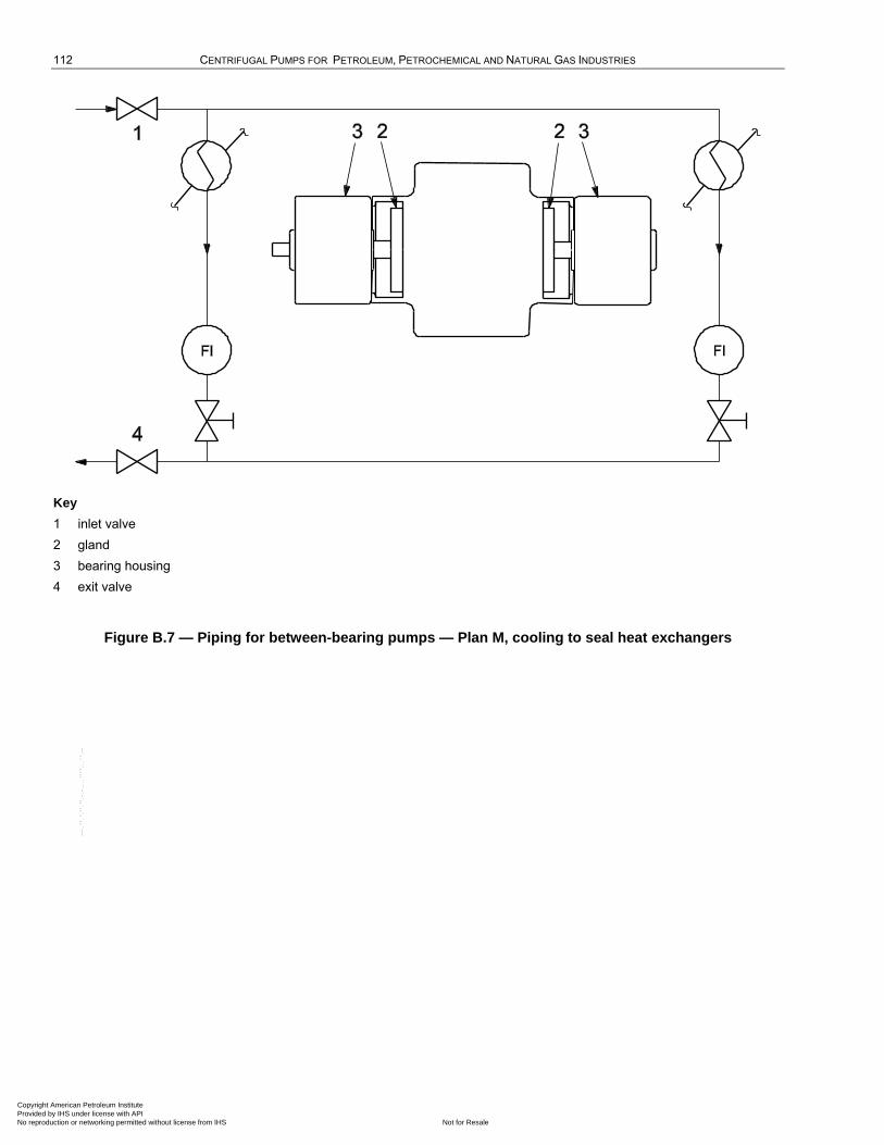
112 CENTRIFUGAL PUMPS FOR PETROLEUM, PETROCHEMICAL AND NATURAL GAS INDUSTRIES
Key
1 inlet valve
2 gland
3 bearing housing
4 exit valve
Figure B.7 — Piping for between-bearing pumps — Plan M, cooling to seal heat exchangers
Copyright American Petroleum Institute Provided by IHS under license with API
Not for ResaleNo reproduction or networking permitted without license from IHS
--`,,```,,,,````-`-`,,`,,`,`,,`---

API STANDARD 610/ISO 13709 113
See Table B.1 for description of key items and console class.
NOTE 1 In the title, ―BP0‖ indicates that the baseplate is part of equipment, ―BP1‖ indicates a stand-alone console, reservoir-mounted. The P&IDs are similar.
NOTE 2 Figure modified from ISO 10438-2:2007, Figure B.1. For the purposes of this provision, API 614-08 is the equivalent of ISO 10438-2:2007.
Figure B.8 — Class II-P0-R1-H0-BP0-C1F2-C0-PV1-TV1-BB0 or Class II-P0-R1-H0-BP1-C1F2-C0-PV1-TV1-BB0
Copyright American Petroleum Institute Provided by IHS under license with API
Not for ResaleNo reproduction or networking permitted without license from IHS
--`,,```,,,,````-`-`,,`,,`,`,,`---
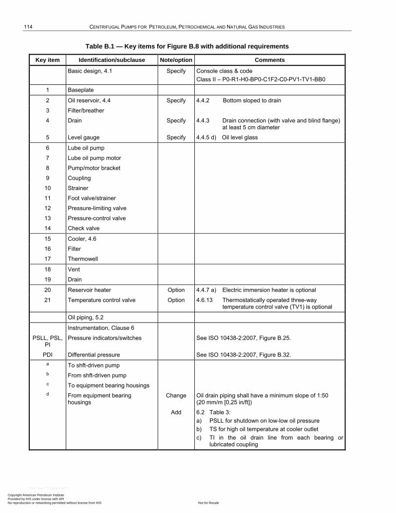
114 CENTRIFUGAL PUMPS FOR PETROLEUM, PETROCHEMICAL AND NATURAL GAS INDUSTRIES
Table B.1 — Key items for Figure B.8 with additional requirements
Key item Identification/subclause Note/option Comments
Basic design, 4.1 Specify Console class & code
Class II – P0-R1-H0-BP0-C1F2-C0-PV1-TV1-BB0
1 Baseplate
2 Oil reservoir, 4.4 Specify 4.4.2 Bottom sloped to drain
3 Filter/breather
4 Drain Specify 4.4.3 Drain connection (with valve and blind flange) at least 5 cm diameter
5 Level gauge Specify 4.4.5 d) Oil level glass
6 Lube oil pump
7 Lube oil pump motor
8 Pump/motor bracket
9 Coupling
10 Strainer
11 Foot valve/strainer
12 Pressure-limiting valve
13 Pressure-control valve
14 Check valve
15 Cooler, 4.6
16 Filter
17 Thermowell
18 Vent
19 Drain
20 Reservoir heater Option 4.4.7 a) Electric immersion heater is optional
21 Temperature control valve Option 4.6.13 Thermostatically operated three-way temperature control valve (TV1) is optional
Oil piping, 5.2
Instrumentation, Clause 6
PSLL, PSL, PI
Pressure indicators/switches See ISO 10438-2:2007, Figure B.25.
PDI Differential pressure See ISO 10438-2:2007, Figure B.32.
a To shft-driven pump
b From shft-driven pump
c To equipment bearing housings
d From equipment bearing housings
Change Oil drain piping shall have a minimum slope of 1:50 (20 mm/m [0,25 in/ft])
Add 6.2 Table 3:
a) PSLL for shutdown on low-low oil pressure
b) TS for high oil temperature at cooler outlet
c) TI in the oil drain line from each bearing or lubricated coupling
Copyright American Petroleum Institute Provided by IHS under license with API
Not for ResaleNo reproduction or networking permitted without license from IHS
--`,,```,,,,````-`-`,,`,,`,`,,`---
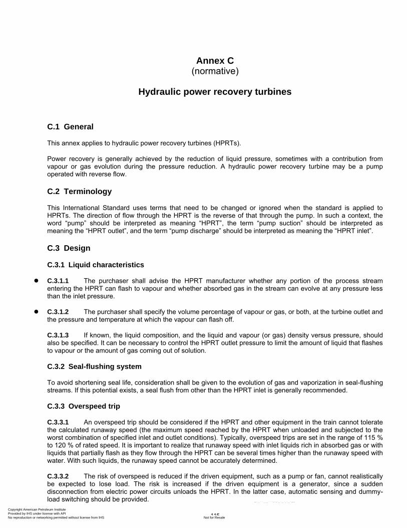
115
Annex C (normative)
Hydraulic power recovery turbines
C.1 General
This annex applies to hydraulic power recovery turbines (HPRTs).
Power recovery is generally achieved by the reduction of liquid pressure, sometimes with a contribution from vapour or gas evolution during the pressure reduction. A hydraulic power recovery turbine may be a pump operated with reverse flow.
C.2 Terminology
This International Standard uses terms that need to be changed or ignored when the standard is applied to HPRTs. The direction of flow through the HPRT is the reverse of that through the pump. In such a context, the word ―pump‖ should be interpreted as meaning ―HPRT‖, the term ―pump suction‖ should be interpreted as meaning the ―HPRT outlet‖, and the term ―pump discharge‖ should be interpreted as meaning the ―HPRT inlet‖.
C.3 Design
C.3.1 Liquid characteristics
C.3.1.1 The purchaser shall advise the HPRT manufacturer whether any portion of the process stream entering the HPRT can flash to vapour and whether absorbed gas in the stream can evolve at any pressure less than the inlet pressure.
C.3.1.2 The purchaser shall specify the volume percentage of vapour or gas, or both, at the turbine outlet and the pressure and temperature at which the vapour can flash off.
C.3.1.3 If known, the liquid composition, and the liquid and vapour (or gas) density versus pressure, should also be specified. It can be necessary to control the HPRT outlet pressure to limit the amount of liquid that flashes to vapour or the amount of gas coming out of solution.
C.3.2 Seal-flushing system
To avoid shortening seal life, consideration shall be given to the evolution of gas and vaporization in seal-flushing streams. If this potential exists, a seal flush from other than the HPRT inlet is generally recommended.
C.3.3 Overspeed trip
C.3.3.1 An overspeed trip should be considered if the HPRT and other equipment in the train cannot tolerate the calculated runaway speed (the maximum speed reached by the HPRT when unloaded and subjected to the worst combination of specified inlet and outlet conditions). Typically, overspeed trips are set in the range of 115 % to 120 % of rated speed. It is important to realize that runaway speed with inlet liquids rich in absorbed gas or with liquids that partially flash as they flow through the HPRT can be several times higher than the runaway speed with water. With such liquids, the runaway speed cannot be accurately determined.
C.3.3.2 The risk of overspeed is reduced if the driven equipment, such as a pump or fan, cannot realistically be expected to lose load. The risk is increased if the driven equipment is a generator, since a sudden disconnection from electric power circuits unloads the HPRT. In the latter case, automatic sensing and dummy-load switching should be provided.
Copyright American Petroleum Institute Provided by IHS under license with API
Not for ResaleNo reproduction or networking permitted without license from IHS
--`,,```,,,,````-`-`,,`,,`,`,,`---

116 CENTRIFUGAL PUMPS FOR PETROLEUM, PETROCHEMICAL AND NATURAL GAS INDUSTRIES
C.3.3.3 Rotor systems that have low inertia and are subject to accidental unloading should be equipped with a quick-acting brake to prevent damage from overspeed.
C.3.4 Dual drivers
NOTE See Figures C.1 a) and b).
C.3.4.1 If an HPRT is used to assist another driver, the considerations in C.3.4.2 through C.3.4.5 apply.
C.3.4.2 The main driver should be rated to drive the train without assistance from the HPRT.
C.3.4.3 An overrunning clutch (that is a clutch that transmits torque in one direction and freewheels in the other) should generally be used between the HPRT and the train to allow the driven equipment to operate during HPRT maintenance and to permit start-up of the train before the HPRT process stream is lined up.
C.3.4.4 Flow to the HPRT can vary widely and frequently. If the flow drops to about 40 % of the rated flow, the HPRT stops producing power and a drag can be imposed on the main driver. An overrunning clutch prevents this drag.
C.3.4.5 The HPRT should never be placed between the main driver and the driven equipment.
C.3.5 Generators
NOTE See Figure C.1 c).
If a generator is driven by an HPRT on a gas-rich process stream, the generator should be generously sized. The output power of HPRTs can be as much as 20 % to 30 % or more above that predicted by water tests, as a result of the effects of evolved gas or flashed liquid.
C.3.6 Throttle valves
For most applications, valves used to control flow to the HPRT should be placed upstream and near the inlet of the HPRT (see Figure C.1). Placement upstream allows the mechanical seals to operate at the outlet pressure of the HPRT and, for gas-rich streams, permits the gas to evolve, which increases the power output.
C.3.7 Bypass valves
Regardless of the arrangement of the HPRT train, a full-flow bypass valve with modulation capability should be installed. Common control of the modulating bypass valve and the HPRT inlet control valve is normally achieved by means of a split-level arrangement (see Figure C.1).
C.3.8 Relief valves
To protect the HPRT outlet casing integrity and mechanical seals from possible downstream back-pressure transients, a relief valve installed in the HPRT outlet piping circuit should be considered (see Figure C.1).
Copyright American Petroleum Institute Provided by IHS under license with API
Not for ResaleNo reproduction or networking permitted without license from IHS
--`,,```,,,,````-`-`,,`,,`,`,,`---
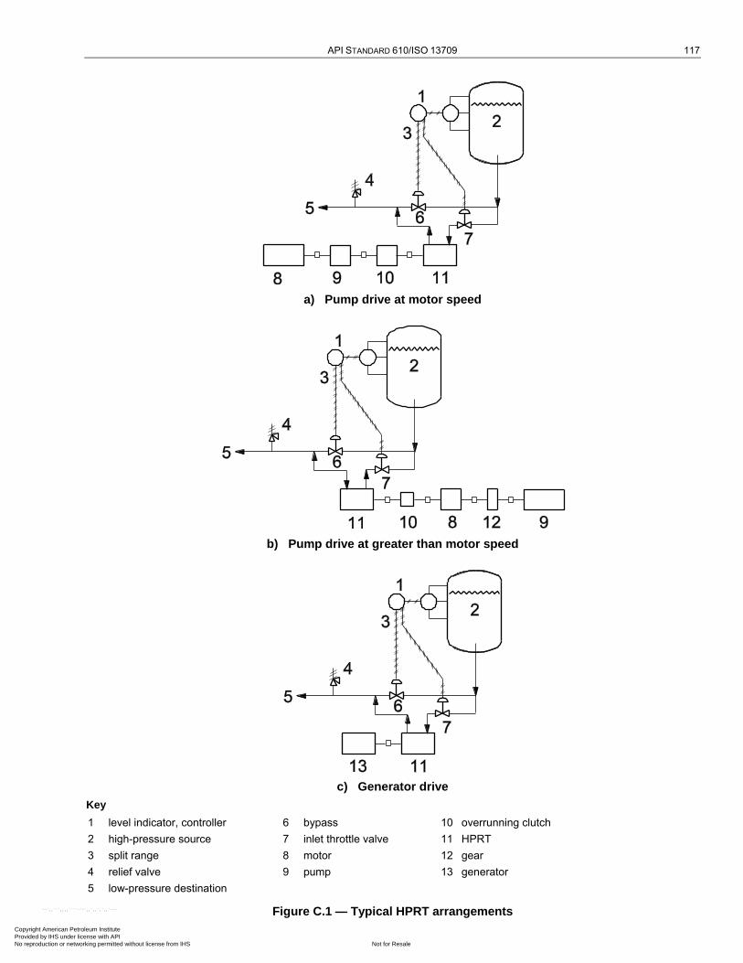
API STANDARD 610/ISO 13709 117
a) Pump drive at motor speed
b) Pump drive at greater than motor speed
c) Generator drive
Key
1 level indicator, controller 6 bypass 10 overrunning clutch
2 high-pressure source 7 inlet throttle valve 11 HPRT
3 split range 8 motor 12 gear
4 relief valve 9 pump 13 generator
5 low-pressure destination
Figure C.1 — Typical HPRT arrangements
Copyright American Petroleum Institute Provided by IHS under license with API
Not for ResaleNo reproduction or networking permitted without license from IHS
--`,,```,,,,````-`-`,,`,,`,`,,`---
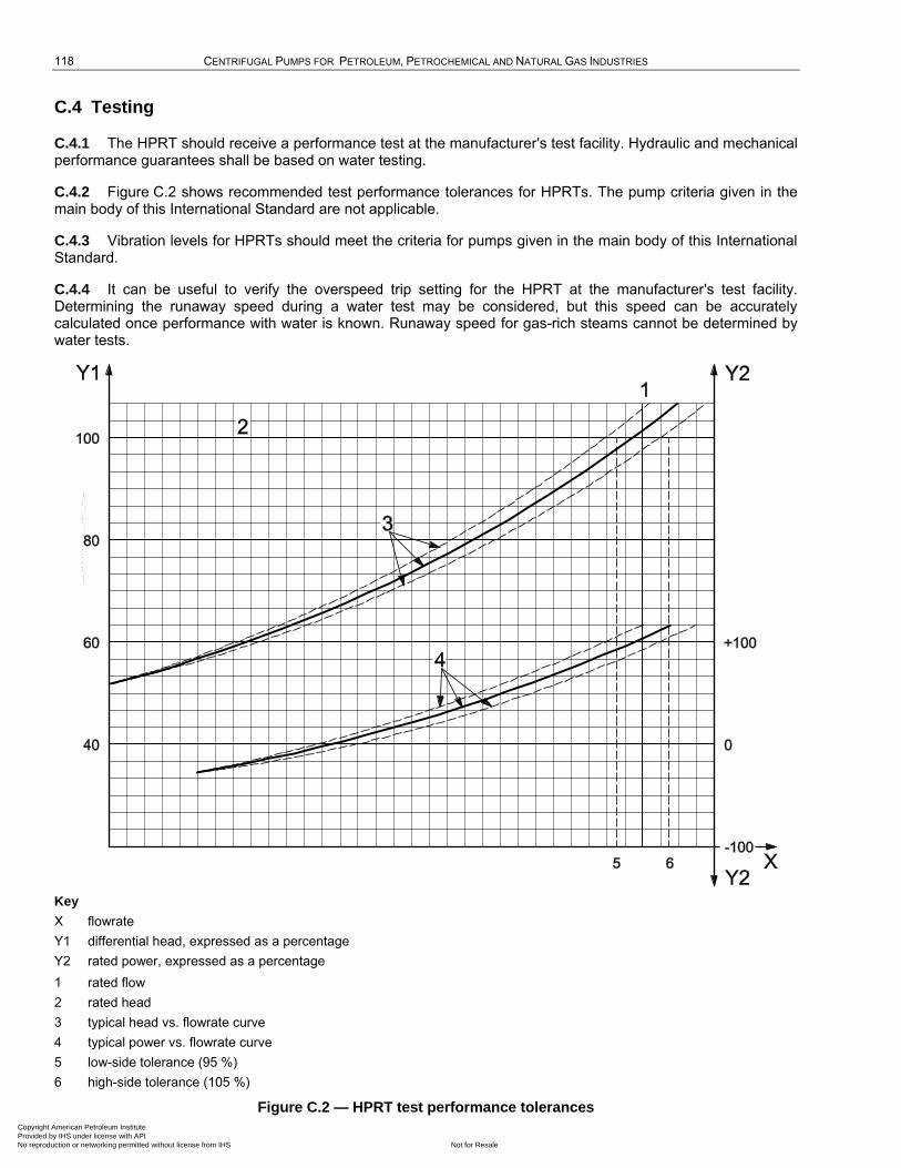
118 CENTRIFUGAL PUMPS FOR PETROLEUM, PETROCHEMICAL AND NATURAL GAS INDUSTRIES
C.4 Testing
C.4.1 The HPRT should receive a performance test at the manufacturer's test facility. Hydraulic and mechanical performance guarantees shall be based on water testing.
C.4.2 Figure C.2 shows recommended test performance tolerances for HPRTs. The pump criteria given in the main body of this International Standard are not applicable.
C.4.3 Vibration levels for HPRTs should meet the criteria for pumps given in the main body of this International Standard.
C.4.4 It can be useful to verify the overspeed trip setting for the HPRT at the manufacturer's test facility. Determining the runaway speed during a water test may be considered, but this speed can be accurately calculated once performance with water is known. Runaway speed for gas-rich steams cannot be determined by water tests.
Key
X flowrate
Y1 differential head, expressed as a percentage
Y2 rated power, expressed as a percentage
1 rated flow
2 rated head
3 typical head vs. flowrate curve
4 typical power vs. flowrate curve
5 low-side tolerance (95 %)
6 high-side tolerance (105 %)
Figure C.2 — HPRT test performance tolerances
Copyright American Petroleum Institute Provided by IHS under license with API
Not for ResaleNo reproduction or networking permitted without license from IHS
--`,,```,,,,````-`-`,,`,,`,`,,`---

119
Annex D (normative)
Standard baseplates
Table D.1 — Dimensions of standard baseplates
Dimensions in millimetres (inches)
Baseplate number
Number of holes per side
l1 13 (0,5)
l2 25 (1,0)
l3 3 (0,12)
l4 3 (0,12)
l5 3 (0,12)
0,5 3 760 (30,0) 1 230 (48,5) 465 (18,25) 465 (18,25) 685 (27,0)
1 3 760 (30,0) 1 535 (60,5) 615 (24,25) 615 (24,25) 685 (27,0)
1,5 3 760 (30,0) 1 840 (72,5) 770 (30,25) 770 (30,25) 685 (27,0)
2 4 760 (30,0) 2 145 (84,5) 920 (36,25) 615 (24,16) 685 (27,0)
2,5 3 915 (36,0) 1 535 (60,5) 615 (24,25) 615 (24,25) 840 (33,0)
3 3 915 (36,0) 1 840 (72,5) 770 (30,25) 770 (30,25) 840 (33,0)
3,5 4 915 (36,0) 2 145 (84,5) 920 (36,25) 615 (24,16) 840 (33,0)
4 4 915 (36,0) 2 450 (96,5) 1 075 (42,25) 715 (28,16) 840 (33,0)
5 3 1 065 (42,0) 1 840 (72,5) 770 (30,25) 770 (30,25) 990 (39,0)
5,5 4 1 065 (42,0) 2 145 (84,5) 920 (36,25) 615 (24,16) 990 (39,0)
6 4 1 065 (42,0) 2 450 (96,5) 1 075 (42,25) 715 (28,16) 990 (39,0)
6,5 5 1 065 (42,0) 2 755 (108,5) 1 225 (48,25) 615 (24,12) 990 (39,0)
7 4 1 245 (49,0) 2 145 (84,5) 920 (36,25) 615 (24,16) 1 170 (46,0)
7,5 4 1 245 (49,0) 2 450 (96,5) 1 075 (42,25) 715 (28,16) 1 170 (46,0)
8 5 1 245 (49,0) 2 755 (108,5) 1 225 (48,25) 615 (24,12) 1 170 (46,0)
9 4 1 395 (55,0) 2 145 (84,5) 920 (36,25) 615 (24,16) 1 320 (52,0)
9,5 4 1 395 (55,0) 2 450 (96,5) 1 075 (42,25) 715 (28,16) 1 320 (52,0)
10 5 1 395 (55,0) 2 755 (108,5) 1 225 (48,25) 615 (24,12) 1 320 (52,0)
11 4 1 550 (61,0) 2 145 (84,5) 920 (36,25) 615 (24,16) 1 475 (58,0)
11,5 4 1 550 (61,0) 2 450 (96,5) 1 075 (42,25) 715 (28,16) 1 475 (58,0)
12 5 1 550 (61,0) 2 755 (108,5) 1 225 (48,25) 615 (24,12) 1 475 (58,0)
NOTE See Figure D.1 for explanation of dimensions.
Copyright American Petroleum Institute Provided by IHS under license with API
Not for ResaleNo reproduction or networking permitted without license from IHS
--`,,```,,,,````-`-`,,`,,`,`,,`---
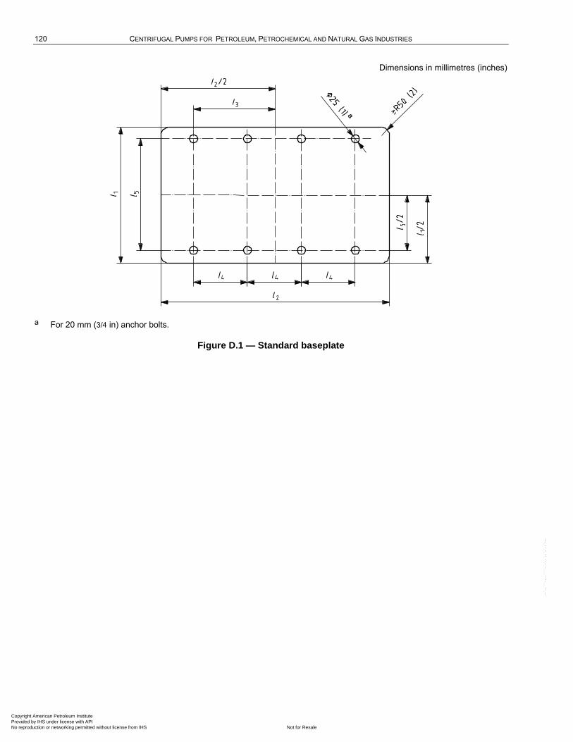
120 CENTRIFUGAL PUMPS FOR PETROLEUM, PETROCHEMICAL AND NATURAL GAS INDUSTRIES
Dimensions in millimetres (inches)
a For 20 mm (3/4 in) anchor bolts.
Figure D.1 — Standard baseplate
Copyright American Petroleum Institute Provided by IHS under license with API
Not for ResaleNo reproduction or networking permitted without license from IHS
--`,,```,,,,````-`-`,,`,,`,`,,`---
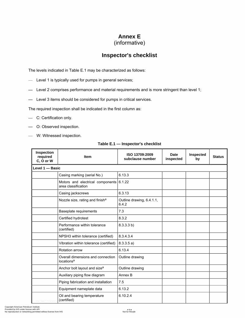
121
Annex E (informative)
Inspector's checklist
The levels indicated in Table E.1 may be characterized as follows:
Level 1 is typically used for pumps in general services;
Level 2 comprises performance and material requirements and is more stringent than level 1;
Level 3 items should be considered for pumps in critical services.
The required inspection shall be indicated in the first column as:
C: Certification only.
O: Observed inspection.
W: Witnessed inspection.
Table E.1 — Inspector's checklist
Inspection required
C, O or W Item
ISO 13709:2009 subclause number
Date inspected
Inspected by
Status
Level 1 — Basic
Casing marking (serial No.) 6.13.3
Motors and electrical components area classification
6.1.22
Casing jackscrews 6.3.13
Nozzle size, rating and finisha Outline drawing, 6.4.1.1, 6.4.2
Baseplate requirements 7.3
Certified hydrotest 8.3.2
Performance within tolerance (certified)
8.3.3.3 b)
NPSH3 within tolerance (certified) 8.3.4.3.4
Vibration within tolerance (certified) 8.3.3.5 a)
Rotation arrow 6.13.4
Overall dimensions and connection locationsa
Outline drawing
Anchor bolt layout and sizea Outline drawing
Auxiliary piping flow diagram Annex B
Piping fabrication and installation 7.5
Equipment nameplate data 6.13.2
Oil and bearing temperature (certified)
6.10.2.4
Copyright American Petroleum Institute Provided by IHS under license with API
Not for ResaleNo reproduction or networking permitted without license from IHS
--`,,```,,,,````-`-`,,`,,`,`,,`---
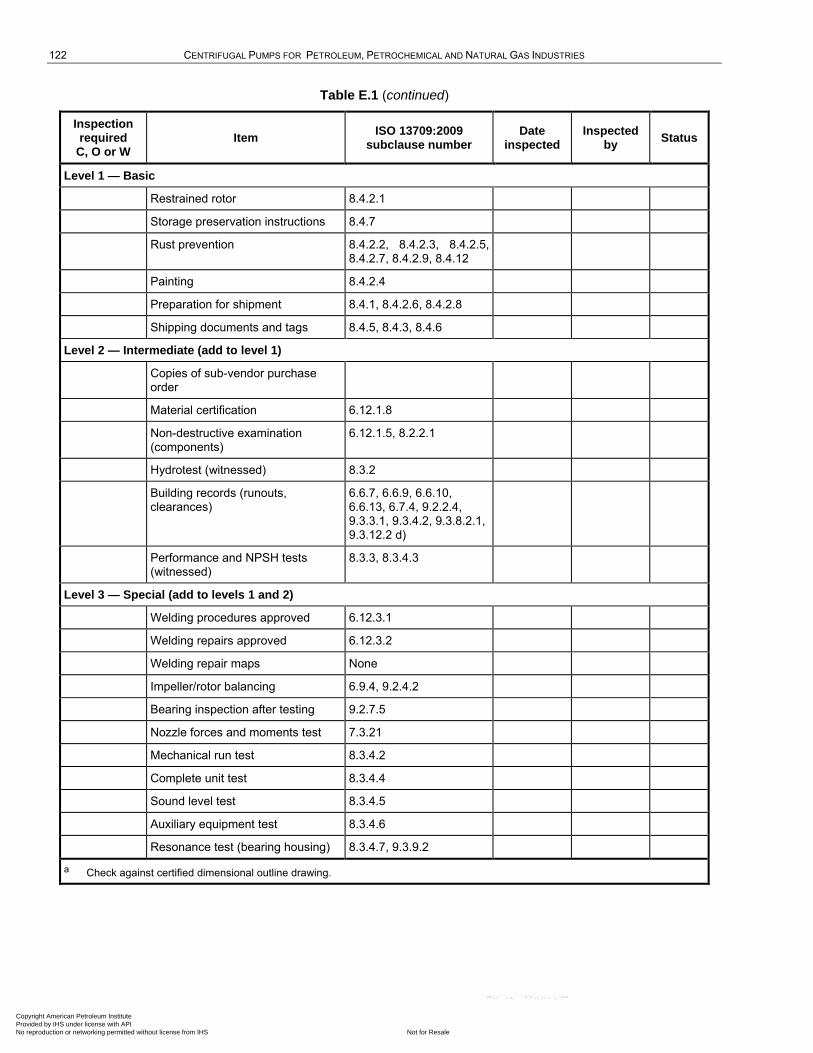
122 CENTRIFUGAL PUMPS FOR PETROLEUM, PETROCHEMICAL AND NATURAL GAS INDUSTRIES
Table E.1 (continued)
Inspection required
C, O or W Item
ISO 13709:2009 subclause number
Date inspected
Inspected by
Status
Level 1 — Basic
Restrained rotor 8.4.2.1
Storage preservation instructions 8.4.7
Rust prevention 8.4.2.2, 8.4.2.3, 8.4.2.5, 8.4.2.7, 8.4.2.9, 8.4.12
Painting 8.4.2.4
Preparation for shipment 8.4.1, 8.4.2.6, 8.4.2.8
Shipping documents and tags 8.4.5, 8.4.3, 8.4.6
Level 2 — Intermediate (add to level 1)
Copies of sub-vendor purchase order
Material certification 6.12.1.8
Non-destructive examination (components)
6.12.1.5, 8.2.2.1
Hydrotest (witnessed) 8.3.2
Building records (runouts, clearances)
6.6.7, 6.6.9, 6.6.10, 6.6.13, 6.7.4, 9.2.2.4, 9.3.3.1, 9.3.4.2, 9.3.8.2.1, 9.3.12.2 d)
Performance and NPSH tests (witnessed)
8.3.3, 8.3.4.3
Level 3 — Special (add to levels 1 and 2)
Welding procedures approved 6.12.3.1
Welding repairs approved 6.12.3.2
Welding repair maps None
Impeller/rotor balancing 6.9.4, 9.2.4.2
Bearing inspection after testing 9.2.7.5
Nozzle forces and moments test 7.3.21
Mechanical run test 8.3.4.2
Complete unit test 8.3.4.4
Sound level test 8.3.4.5
Auxiliary equipment test 8.3.4.6
Resonance test (bearing housing) 8.3.4.7, 9.3.9.2
a Check against certified dimensional outline drawing.
Copyright American Petroleum Institute Provided by IHS under license with API
Not for ResaleNo reproduction or networking permitted without license from IHS
--`,,```,,,,````-`-`,,`,,`,`,,`---
123
Annex F (normative)
Criteria for piping design
F.1 Horizontal pumps
F.1.1 Acceptable piping configurations should not cause excessive misalignment between the pump and driver. Piping configurations that produce component nozzle loads lying within the ranges specified in Table 5 limit casing distortion to one-half the pump vendor's design criterion (see 6.3.3) and ensure pump shaft displacement of less than 250 µm (0,010 in).
F.1.2 Piping configurations that produce loads outside the ranges specified in Table 5 are also acceptable without consultation with the pump vendor if the conditions specified in F.1.2 a) through F.1.2 c) as follows are satisfied. Satisfying these conditions ensures that any pump casing distortion is within the vendor's design criteria (see 6.3.3) and that the displacement of the pump shaft is less than 380 µm (0,015 in).
a) The individual component forces and moments acting on each pump nozzle flange shall not exceed the range specified in Table 5 (T4) by a factor of more than 2.
b) The resultant applied force (FRSA, FRDA) and the resultant applied moment (MRSA, MRDA) acting on each pump-nozzle flange shall satisfy the appropriate interaction equations as given in Equations (F.1) and (F.2):
[FRSA/(1,5 FRST4)] [MRSA/(1,5 MRST4)] 2 (F.1)
[FRDA/(1,5 FRDT4)] [MRDA/(1,5 MRDT4)] 2 (F.2)
c) The applied component forces and moments acting on each pump nozzle flange shall be translated to the centre of the pump. The magnitude of the resultant applied force, FRCA, the resultant applied moment, MRCA, and the applied moment shall be limited by Equations (F.3) to (F.5). (The sign convention shown in Figures 21 through 25 and the right-hand rule should be used in evaluating these equations.)
FRCA 1,5(FRST4 FRDT4) (F.3)
MYCA 2,0(MYST4 MYDT4) (F.4)
MRCA 1,5(MRST4 MRDT4) (F.5)
where
FRCA [(FXCA)2 (FYCA)2 (FZCA)2]0,5
where
FXCA FXSA FXDA
FYCA FYSA FYDA
FZCA FZSA FZDA
MRCA [(MXCA)2 (MYCA)2 (MZCA)2]0,5
Copyright American Petroleum Institute Provided by IHS under license with API
Not for ResaleNo reproduction or networking permitted without license from IHS
--`,,```,,,,````-`-`,,`,,`,`,,`---
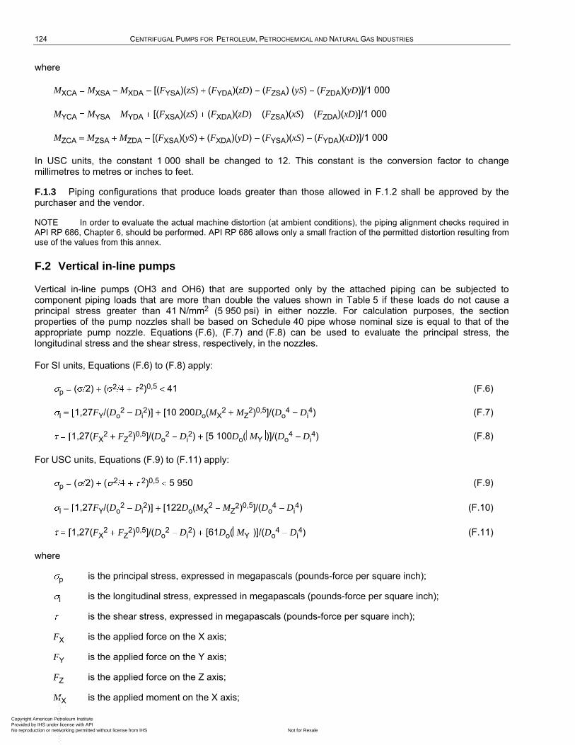
124 CENTRIFUGAL PUMPS FOR PETROLEUM, PETROCHEMICAL AND NATURAL GAS INDUSTRIES
where
MXCA MXSA MXDA [(FYSA)(zS) (FYDA)(zD) (FZSA) (yS) (FZDA)(yD)]/1 000
MYCA MYSA MYDA [(FXSA)(zS) (FXDA)(zD) (FZSA)(xS) (FZDA)(xD)]/1 000
MZCA MZSA MZDA [(FXSA)(yS) (FXDA)(yD) (FYSA)(xS) (FYDA)(xD)]/1 000
In USC units, the constant 1 000 shall be changed to 12. This constant is the conversion factor to change millimetres to metres or inches to feet.
F.1.3 Piping configurations that produce loads greater than those allowed in F.1.2 shall be approved by the purchaser and the vendor.
NOTE In order to evaluate the actual machine distortion (at ambient conditions), the piping alignment checks required in API RP 686, Chapter 6, should be performed. API RP 686 allows only a small fraction of the permitted distortion resulting from use of the values from this annex.
F.2 Vertical in-line pumps
Vertical in-line pumps (OH3 and OH6) that are supported only by the attached piping can be subjected to component piping loads that are more than double the values shown in Table 5 if these loads do not cause a principal stress greater than 41 N/mm2 (5 950 psi) in either nozzle. For calculation purposes, the section properties of the pump nozzles shall be based on Schedule 40 pipe whose nominal size is equal to that of the appropriate pump nozzle. Equations (F.6), (F.7) and (F.8) can be used to evaluate the principal stress, the longitudinal stress and the shear stress, respectively, in the nozzles.
For SI units, Equations (F.6) to (F.8) apply:
p ( 2) ( 2 2)0,5 41 (F.6)
l 1,27FY/(Do2 Di
2)] [10 200Do(MX2 MZ
2)0,5]/(Do4 Di
4) (F.7)
1,27(FX2 FZ
2)0,5]/(Do2 Di
2) [5 100Do( MY )]/(Do4 Di
4) (F.8)
For USC units, Equations (F.9) to (F.11) apply:
p ( 2) ( 2 2)0,5 5 950 (F.9)
l 1,27FY/(Do2 Di
2)] [122Do(MX2 MZ
2)0,5]/(Do4 Di
4) (F.10)
1,27(FX2 FZ
2)0,5]/(Do2 Di
2) [61Do( MY )]/(Do4 Di
4) (F.11)
where
p is the principal stress, expressed in megapascals (pounds-force per square inch);
l is the longitudinal stress, expressed in megapascals (pounds-force per square inch);
is the shear stress, expressed in megapascals (pounds-force per square inch);
FX is the applied force on the X axis;
FY is the applied force on the Y axis;
FZ is the applied force on the Z axis;
MX is the applied moment on the X axis;
Copyright American Petroleum Institute Provided by IHS under license with API
Not for ResaleNo reproduction or networking permitted without license from IHS
--`,,```,,,,````-`-`,,`,,`,`,,`---
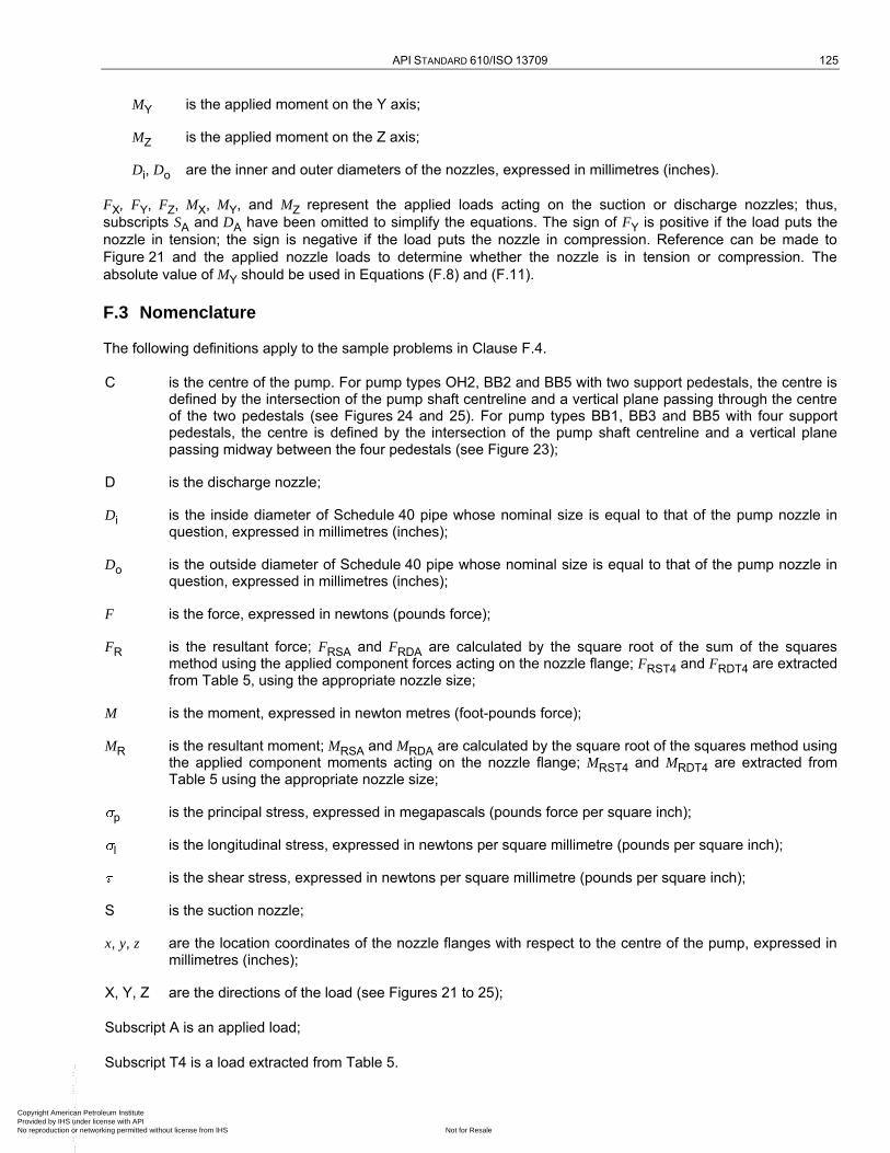
API STANDARD 610/ISO 13709 125
MY is the applied moment on the Y axis;
MZ is the applied moment on the Z axis;
Di, Do are the inner and outer diameters of the nozzles, expressed in millimetres (inches).
FX, FY, FZ, MX, MY, and MZ represent the applied loads acting on the suction or discharge nozzles; thus,
subscripts SA and DA have been omitted to simplify the equations. The sign of FY is positive if the load puts the
nozzle in tension; the sign is negative if the load puts the nozzle in compression. Reference can be made to
Figure 21 and the applied nozzle loads to determine whether the nozzle is in tension or compression. The
absolute value of MY should be used in Equations (F.8) and (F.11).
F.3 Nomenclature
The following definitions apply to the sample problems in Clause F.4.
C is the centre of the pump. For pump types OH2, BB2 and BB5 with two support pedestals, the centre is defined by the intersection of the pump shaft centreline and a vertical plane passing through the centre of the two pedestals (see Figures 24 and 25). For pump types BB1, BB3 and BB5 with four support pedestals, the centre is defined by the intersection of the pump shaft centreline and a vertical plane passing midway between the four pedestals (see Figure 23);
D is the discharge nozzle;
Di is the inside diameter of Schedule 40 pipe whose nominal size is equal to that of the pump nozzle in question, expressed in millimetres (inches);
Do is the outside diameter of Schedule 40 pipe whose nominal size is equal to that of the pump nozzle in question, expressed in millimetres (inches);
F is the force, expressed in newtons (pounds force);
FR is the resultant force; FRSA and FRDA are calculated by the square root of the sum of the squares method using the applied component forces acting on the nozzle flange; FRST4 and FRDT4 are extracted from Table 5, using the appropriate nozzle size;
M is the moment, expressed in newton metres (foot-pounds force);
MR is the resultant moment; MRSA and MRDA are calculated by the square root of the squares method using the applied component moments acting on the nozzle flange; MRST4 and MRDT4 are extracted from Table 5 using the appropriate nozzle size;
p is the principal stress, expressed in megapascals (pounds force per square inch);
l is the longitudinal stress, expressed in newtons per square millimetre (pounds per square inch);
is the shear stress, expressed in newtons per square millimetre (pounds per square inch);
S is the suction nozzle;
x, y, z are the location coordinates of the nozzle flanges with respect to the centre of the pump, expressed in millimetres (inches);
X, Y, Z are the directions of the load (see Figures 21 to 25);
Subscript A is an applied load;
Subscript T4 is a load extracted from Table 5.
Copyright American Petroleum Institute Provided by IHS under license with API
Not for ResaleNo reproduction or networking permitted without license from IHS
--`,,```,,,,````-`-`,,`,,`,`,,`---
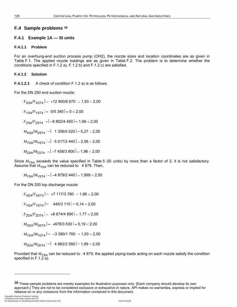
126 CENTRIFUGAL PUMPS FOR PETROLEUM, PETROCHEMICAL AND NATURAL GAS INDUSTRIES
F.4 Sample problems 16
F.4.1 Example 1A — SI units
F.4.1.1 Problem
For an overhung-end suction process pump (OH2), the nozzle sizes and location coordinates are as given in Table F.1. The applied nozzle loadings are as given in Table F.2. The problem is to determine whether the conditions specified in F.1.2 a), F.1.2 b) and F.1.2 c) are satisfied.
F.4.1.2 Solution
F.4.1.2.1 A check of condition F.1.2 a) is as follows.
For the DN 250 end suction nozzle:
FXSA/FXST4 12 900/6 670 1,93 2,00
FYSA/FYST4 0/5 340 0 2,00
FZSA/FZST4 8 852/4 450 1,99 2,00
MXSA/MXST4 1 356/5 020 0,27 2,00
MYSA/MYST4 5 017/2 440 2,06 2,00
MZSA/MZST4 7 458/3 800 1,96 2,00
Since MYSA exceeds the value specified in Table 5 (SI units) by more than a factor of 2, it is not satisfactory. Assume that MYSA can be reduced to 4 879. Then,
MYSA/MYST4 4 879/2 440 1,999 2,00
For the DN 200 top discharge nozzle:
FXDA/FXDT4 7 117/3 780 1,88 2,00
FYDA/FYDT4 445/3 110 0,14 2,00
FZDA/FZDT4 8 674/4 890 1,77 2,00
MXDA/MXDT4 678/3 530 0,19 2,00
MYDA/MYDT4 3 390/1 760 1,93 2,00
MZDA/MZDT4 4 882/2 580 1,89 2,00
Provided that MYSA can be reduced to 4 879, the applied piping loads acting on each nozzle satisfy the condition specified in F.1.2 a).
16 These sample problems are merely examples for illustration purposes only. [Each company should develop its own approach.] They are not to be considered exclusive or exhaustive in nature. API makes no warranties, express or implied for reliance on or any omissions from the information contained in this document.
Copyright American Petroleum Institute Provided by IHS under license with API
Not for ResaleNo reproduction or networking permitted without license from IHS
--`,,```,,,,````-`-`,,`,,`,`,,`---
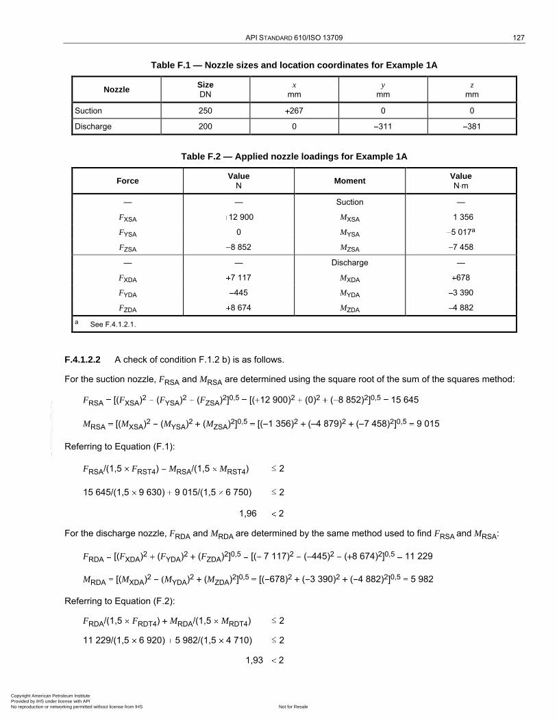
API STANDARD 610/ISO 13709 127
Table F.1 — Nozzle sizes and location coordinates for Example 1A
Nozzle Size DN
x
mm
y
mm
z
mm
Suction 250 267 0 0
Discharge 200 0 311 381
Table F.2 — Applied nozzle loadings for Example 1A
Force Value
N Moment
Value N m
— — Suction —
FXSA 12 900 MXSA 1 356
FYSA 0 MYSA 5 017a
FZSA 8 852 MZSA 7 458
— — Discharge —
FXDA 7 117 MXDA 678
FYDA 445 MYDA 3 390
FZDA 8 674 MZDA 4 882
a See F.4.1.2.1.
F.4.1.2.2 A check of condition F.1.2 b) is as follows.
For the suction nozzle, FRSA and MRSA are determined using the square root of the sum of the squares method:
FRSA [(FXSA)2 (FYSA)2 (FZSA)2]0,5 [( 12 900)2 (0)2 ( 8 852)2]0,5 15 645
MRSA [(MXSA)2 (MYSA)2 (MZSA)2]0,5 [( 1 356)2 ( 4 879)2 ( 7 458)2]0,5 9 015
Referring to Equation (F.1):
FRSA/(1,5 FRST4) MRSA/(1,5 MRST4) ≤ 2
15 645/(1,5 9 630) 9 015/(1,5 6 750) ≤ 2
1,96 2
For the discharge nozzle, FRDA and MRDA are determined by the same method used to find FRSA and MRSA:
FRDA [(FXDA)2 (FYDA)2 (FZDA)2]0,5 [( 7 117)2 ( 445)2 ( 8 674)2]0,5 11 229
MRDA [(MXDA)2 (MYDA)2 (MZDA)2]0,5 [( 678)2 ( 3 390)2 ( 4 882)2]0,5 5 982
Referring to Equation (F.2):
FRDA/(1,5 FRDT4) MRDA/(1,5 MRDT4) ≤ 2
11 229/(1,5 6 920) 5 982/(1,5 4 710) ≤ 2
1,93 2
Copyright American Petroleum Institute Provided by IHS under license with API
Not for ResaleNo reproduction or networking permitted without license from IHS
--`,,```,,,,````-`-`,,`,,`,`,,`---
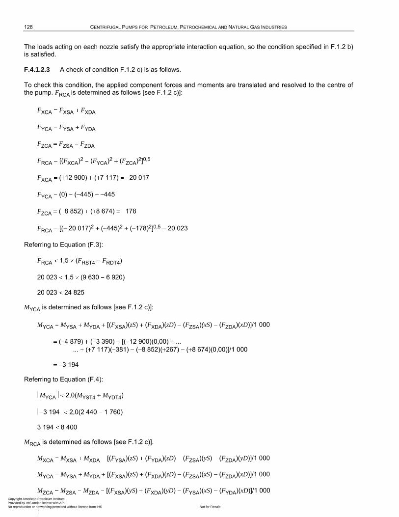
128 CENTRIFUGAL PUMPS FOR PETROLEUM, PETROCHEMICAL AND NATURAL GAS INDUSTRIES
The loads acting on each nozzle satisfy the appropriate interaction equation, so the condition specified in F.1.2 b) is satisfied.
F.4.1.2.3 A check of condition F.1.2 c) is as follows.
To check this condition, the applied component forces and moments are translated and resolved to the centre of the pump. FRCA is determined as follows [see F.1.2 c)]:
FXCA FXSA FXDA
FYCA FYSA FYDA
FZCA FZSA FZDA
FRCA [(FXCA)2 (FYCA)2 (FZCA)2]0,5
FXCA ( 12 900) ( 7 117) 20 017
FYCA (0) ( 445) 445
FZCA ( 8 852) ( 8 674) 178
FRCA [( 20 017)2 ( 445)2 ( 178)2]0,5 20 023
Referring to Equation (F.3):
FRCA 1,5 (FRST4 FRDT4)
20 023 1,5 (9 630 6 920)
20 023 24 825
MYCA is determined as follows [see F.1.2 c)]:
MYCA MYSA MYDA [(FXSA)(zS) (FXDA)(zD) (FZSA)(xS) (FZDA)(xD)]/1 000
( 4 879) ( 3 390) [( 12 900)(0,00) ...
... ( 7 117)( 381) ( 8 852)( 267) ( 8 674)(0,00)]/1 000
3 194
Referring to Equation (F.4):
MYCA 2,0(MYST4 MYDT4)
3 194 2,0(2 440 1 760)
3 194 8 400
MRCA is determined as follows [see F.1.2 c)].
MXCA MXSA MXDA [(FYSA)(zS) (FYDA)(zD) (FZSA)(yS) (FZDA)(yD)]/1 000
MYCA MYSA MYDA [(FXSA)(zS) (FXDA)(zD) (FZSA)(xS) (FZDA)(xD)]/1 000
MZCA MZSA MZDA [(FXSA)(yS) (FXDA)(yD) (FYSA)(xS) (FYDA)(xD)]/1 000 Copyright American Petroleum Institute Provided by IHS under license with API
Not for ResaleNo reproduction or networking permitted without license from IHS
--`,,```,,,,````-`-`,,`,,`,`,,`---
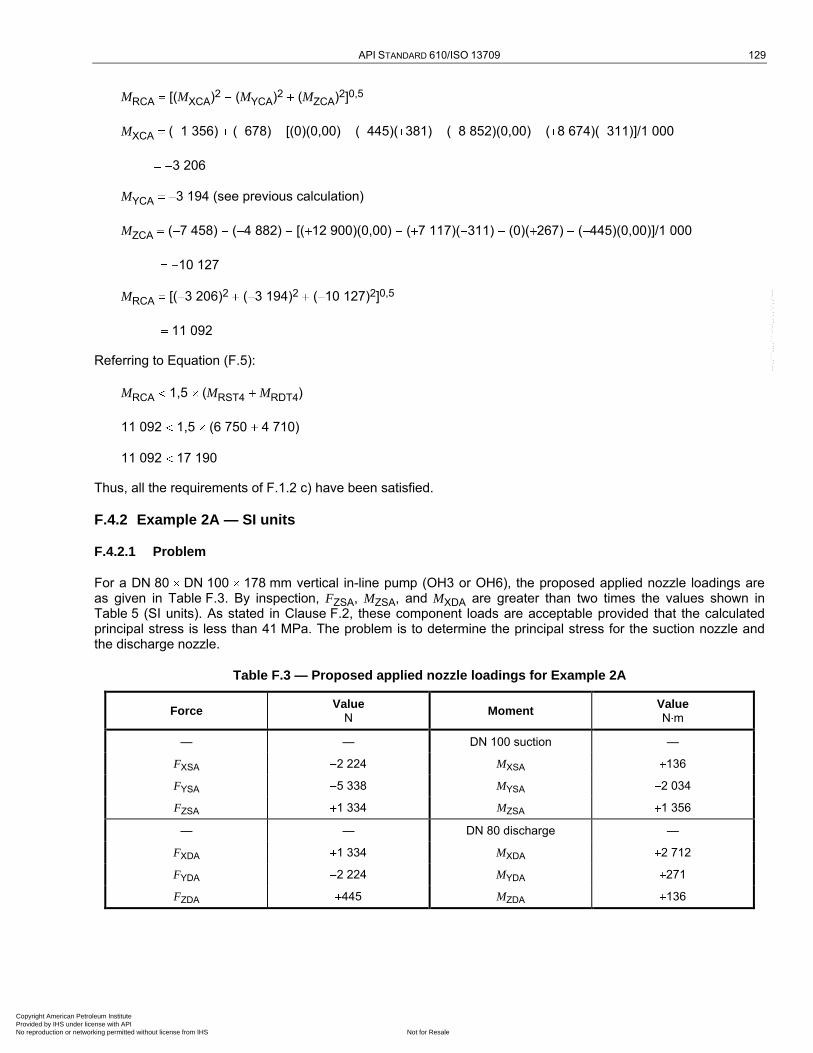
API STANDARD 610/ISO 13709 129
MRCA [(MXCA)2 (MYCA)2 (MZCA)2]0,5
MXCA ( 1 356) ( 678) [(0)(0,00) ( 445)( 381) ( 8 852)(0,00) ( 8 674)( 311)]/1 000
3 206
MYCA 3 194 (see previous calculation)
MZCA ( 7 458) ( 4 882) [( 12 900)(0,00) ( 7 117)( 311) (0)( 267) ( 445)(0,00)]/1 000
10 127
MRCA [( 3 206)2 ( 3 194)2 ( 10 127)2]0,5
11 092
Referring to Equation (F.5):
MRCA 1,5 (MRST4 MRDT4)
11 092 1,5 (6 750 4 710)
11 092 17 190
Thus, all the requirements of F.1.2 c) have been satisfied.
F.4.2 Example 2A — SI units
F.4.2.1 Problem
For a DN 80 DN 100 178 mm vertical in-line pump (OH3 or OH6), the proposed applied nozzle loadings are as given in Table F.3. By inspection, FZSA, MZSA, and MXDA are greater than two times the values shown in Table 5 (SI units). As stated in Clause F.2, these component loads are acceptable provided that the calculated principal stress is less than 41 MPa. The problem is to determine the principal stress for the suction nozzle and the discharge nozzle.
Table F.3 — Proposed applied nozzle loadings for Example 2A
Force Value
N Moment
Value N m
— — DN 100 suction —
FXSA 2 224 MXSA 136
FYSA 5 338 MYSA 2 034
FZSA 1 334 MZSA 1 356
— — DN 80 discharge —
FXDA 1 334 MXDA 2 712
FYDA 2 224 MYDA 271
FZDA 445 MZDA 136
Copyright American Petroleum Institute Provided by IHS under license with API
Not for ResaleNo reproduction or networking permitted without license from IHS
--`,,```,,,,````-`-`,,`,,`,`,,`---
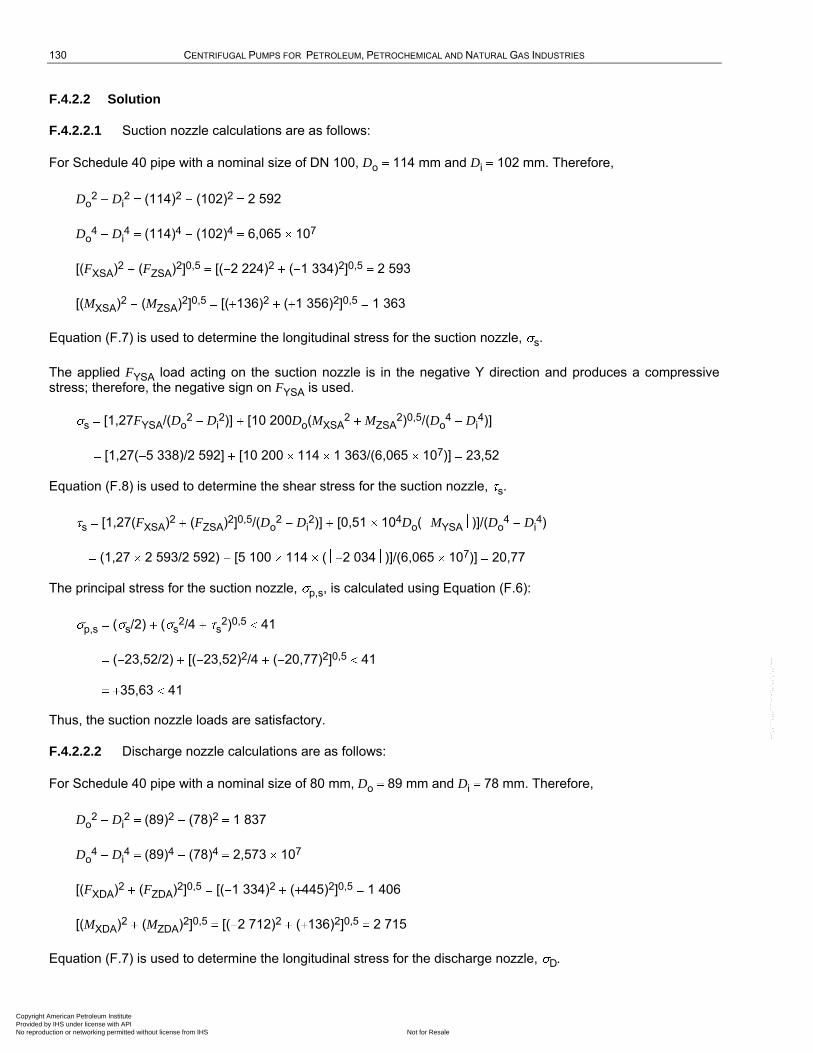
130 CENTRIFUGAL PUMPS FOR PETROLEUM, PETROCHEMICAL AND NATURAL GAS INDUSTRIES
F.4.2.2 Solution
F.4.2.2.1 Suction nozzle calculations are as follows:
For Schedule 40 pipe with a nominal size of DN 100, Do 114 mm and Di 102 mm. Therefore,
Do2 Di
2 (114)2 (102)2 2 592
Do4 Di
4 (114)4 (102)4 6,065 107
[(FXSA)2 (FZSA)2]0,5 [( 2 224)2 ( 1 334)2]0,5 2 593
[(MXSA)2 (MZSA)2]0,5 [( 136)2 ( 1 356)2]0,5 1 363
Equation (F.7) is used to determine the longitudinal stress for the suction nozzle, s.
The applied FYSA load acting on the suction nozzle is in the negative Y direction and produces a compressive stress; therefore, the negative sign on FYSA is used.
s [1,27FYSA/(Do2 Di
2)] [10 200Do(MXSA2 MZSA
2)0,5/(Do4 Di
4)]
[1,27( 5 338)/2 592] [10 200 114 1 363/(6,065 107)] 23,52
Equation (F.8) is used to determine the shear stress for the suction nozzle, s.
s [1,27(FXSA)2 (FZSA)2]0,5/(Do2 Di
2)] [0,51 104Do( MYSA )]/(Do4 Di
4)
(1,27 2 593/2 592) [5 100 114 ( 2 034 )]/(6,065 107)] 20,77
The principal stress for the suction nozzle, p,s, is calculated using Equation (F.6):
p,s ( s/2) ( s2/4 s
2)0,5 41
( 23,52/2) [( 23,52)2/4 ( 20,77)2]0,5 41
35,63 41
Thus, the suction nozzle loads are satisfactory.
F.4.2.2.2 Discharge nozzle calculations are as follows:
For Schedule 40 pipe with a nominal size of 80 mm, Do 89 mm and Di 78 mm. Therefore,
Do2 Di
2 (89)2 (78)2 1 837
Do4 Di
4 (89)4 (78)4 2,573 107
[(FXDA)2 (FZDA)2]0,5 [( 1 334)2 ( 445)2]0,5 1 406
[(MXDA)2 (MZDA)2]0,5 [( 2 712)2 ( 136)2]0,5 2 715
Equation (F.7) is used to determine the longitudinal stress for the discharge nozzle, D.
Copyright American Petroleum Institute Provided by IHS under license with API
Not for ResaleNo reproduction or networking permitted without license from IHS
--`,,```,,,,````-`-`,,`,,`,`,,`---
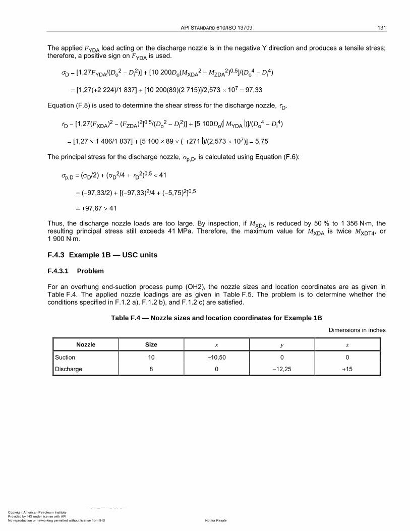
API STANDARD 610/ISO 13709 131
The applied FYDA load acting on the discharge nozzle is in the negative Y direction and produces a tensile stress; therefore, a positive sign on FYDA is used.
D [1,27FYDA/(Do2 Di
2)] [10 200Do(MXDA2 MZDA
2)0,5]/(Do4 Di
4)
[1,27( 2 224)/1 837] [10 200(89)(2 715)]/2,573 107 97,33
Equation (F.8) is used to determine the shear stress for the discharge nozzle, D.
D [1,27(FXDA)2 (FZDA)2]0,5/(Do2 Di
2)] [5 100Do( MYDA )]/(Do4 Di
4)
[1,27 1 406/1 837] [5 100 89 ( 271 )/(2,573 107)] 5,75
The principal stress for the discharge nozzle, p,D, is calculated using Equation (F.6):
p,D ( D/2) ( D2/4 D
2)0,5 41
( 97,33/2) [( 97,33)2/4 ( 5,75)2]0,5
97,67 41
Thus, the discharge nozzle loads are too large. By inspection, if MXDA is reduced by 50 % to 1 356 N m, the resulting principal stress still exceeds 41 MPa. Therefore, the maximum value for MXDA is twice MXDT4, or 1 900 N m.
F.4.3 Example 1B — USC units
F.4.3.1 Problem
For an overhung end-suction process pump (OH2), the nozzle sizes and location coordinates are as given in Table F.4. The applied nozzle loadings are as given in Table F.5. The problem is to determine whether the conditions specified in F.1.2 a), F.1.2 b), and F.1.2 c) are satisfied.
Table F.4 — Nozzle sizes and location coordinates for Example 1B
Dimensions in inches
Nozzle Size x y z
Suction 10 10,50 0 0
Discharge 8 0 12,25 15
Copyright American Petroleum Institute Provided by IHS under license with API
Not for ResaleNo reproduction or networking permitted without license from IHS
--`,,```,,,,````-`-`,,`,,`,`,,`---
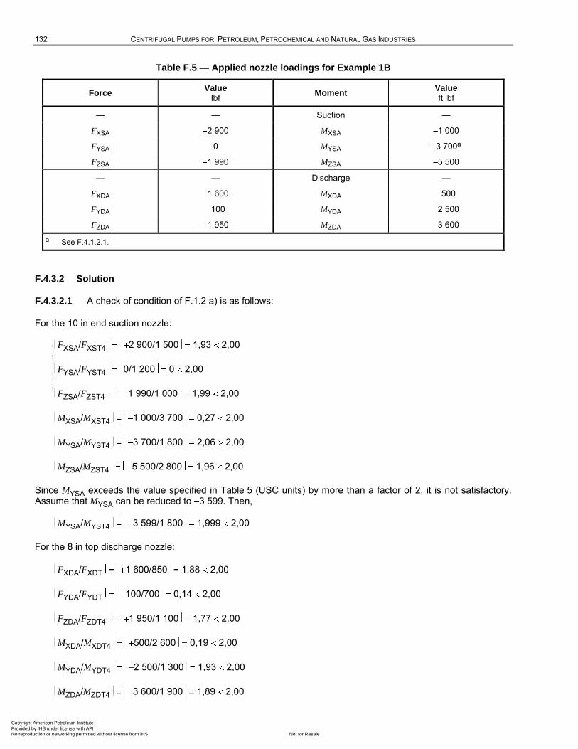
132 CENTRIFUGAL PUMPS FOR PETROLEUM, PETROCHEMICAL AND NATURAL GAS INDUSTRIES
Table F.5 — Applied nozzle loadings for Example 1B
Force Value
lbf Moment
Value ft lbf
— — Suction —
FXSA 2 900 MXSA 1 000
FYSA 0 MYSA 3 700a
FZSA 1 990 MZSA 5 500
— — Discharge —
FXDA 1 600 MXDA 500
FYDA 100 MYDA 2 500
FZDA 1 950 MZDA 3 600
a See F.4.1.2.1.
F.4.3.2 Solution
F.4.3.2.1 A check of condition of F.1.2 a) is as follows:
For the 10 in end suction nozzle:
FXSA/FXST4 2 900/1 500 1,93 2,00
FYSA/FYST4 0/1 200 0 2,00
FZSA/FZST4 1 990/1 000 1,99 2,00
MXSA/MXST4 1 000/3 700 0,27 2,00
MYSA/MYST4 3 700/1 800 2,06 2,00
MZSA/MZST4 5 500/2 800 1,96 2,00
Since MYSA exceeds the value specified in Table 5 (USC units) by more than a factor of 2, it is not satisfactory. Assume that MYSA can be reduced to 3 599. Then,
MYSA/MYST4 3 599/1 800 1,999 2,00
For the 8 in top discharge nozzle:
FXDA/FXDT 1 600/850 1,88 2,00
FYDA/FYDT 100/700 0,14 2,00
FZDA/FZDT4 1 950/1 100 1,77 2,00
MXDA/MXDT4 500/2 600 0,19 2,00
MYDA/MYDT4 2 500/1 300 1,93 2,00
MZDA/MZDT4 3 600/1 900 1,89 2,00
Copyright American Petroleum Institute Provided by IHS under license with API
Not for ResaleNo reproduction or networking permitted without license from IHS
--`,,```,,,,````-`-`,,`,,`,`,,`---

API STANDARD 610/ISO 13709 133
Provided that MYSA can be reduced to 3 599, the applied piping loads acting on each nozzle satisfy the condition specified in F.1.2 a).
F.4.3.2.2 A check of condition F.1.2 b) is as follows:
For the suction nozzle, FRSA and MRSA are determined using the square root of the sum of the squares method:
FRSA [(FXSA)2 (FYSA)2 (FZSA)2]0,5 [( 2 900)2 (0)2 ( 1 990)2]0,5 3 517
MRSA [(MXSA)2 (MYSA)2 (MZSA)2]0,5 [( 1 000)2 ( 3 599)2 ( 5 500)2]0,5 6 649
Referring to Equation (F.1),
FRSA/(1,5 FRST4) MRSA/(1,5 MRST4) 2
3 517/(1,5 2 200) 6 649/(1,5 5 000) 2
1,95 2
For the discharge nozzle, FRDA and MRDA are determined by the same method used to find FRSA and MRSA:
FRDA [(FXDA)2 (FYDA)2 (FZDA)2]0,5 [( 1 600)2 ( 100)2 ( 1 950)2]0,5 2 524
MRDA [MXDA)2 (MYDA)2 (MZDA)2]0,5 [( 500)2 ( 2 500)2 ( 3 600)2]0,5 4 411
Referring to Equation (F.2),
FRDA/(1,5 FRDT4) MRDA/(1,5 MRDT4) 2
2 524/(1,5 1 560) 4 411/(1,5 3 500) 2
1,92 2
The loads acting on each nozzle satisfy the appropriate interaction equation, so the condition specified in F.1.2 b) is satisfied.
F.4.3.2.3 A check of condition F.1.2 c) is as follows.
To check this condition, the applied component forces and moments are translated and resolved to the centre of the pump. FRCA is determined as follows [see F.1.2 c)]:
FXCA FXSA FXDA
FYCA FYSA FYDA
FZCA FZSA FZDA
FRCA [(FXCA)2 (FYCA)2 (FZCA)2]0,5
FXCA ( 2 900) ( 1 600) 4 500
FYCA (0) ( 100) 100
FZCA ( 1 990) ( 1 950) 40
FRCA [( 4 500)2 ( 100)2 ( 40)2]0,5 4 501
Copyright American Petroleum Institute Provided by IHS under license with API
Not for ResaleNo reproduction or networking permitted without license from IHS
--`,,```,,,,````-`-`,,`,,`,`,,`---
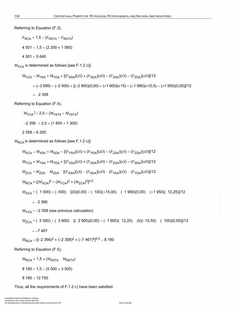
134 CENTRIFUGAL PUMPS FOR PETROLEUM, PETROCHEMICAL AND NATURAL GAS INDUSTRIES
Referring to Equation (F.3),
FRCA 1,5 (FRST4 FRDT4)
4 501 1,5 (2 200 1 560)
4 501 5 640
MYCA is determined as follows [see F.1.2 c)]:
MYCA MYSA MYDA [(FXSA)(zS) (FXDA)(zD) (FZSA)(xS) (FZDA)(xD)]/12
( 3 599) ( 2 500) [( 2 900)(0,00) ( 1 600)( 15) ( 1 990)( 10,5) ( 1 950)(0,00)]/12
2 358
Referring to Equation (F.4),
MYCA 2,0 (MYST4 MYDT4)
2 358 2,0 (1 800 1 300)
2 358 6 200
MRCA is determined as follows [see F.1.2 c)]:
MXCA MXSA MXDA [(FYSA)(zS) (FYDA)(zD) (FZSA)(yS) (FZDA)(yD)]/12
MYCA MYSA MYDA [(FXSA)(zS) (FXDA)(zD) (FZSA)(xS) (FZDA)(xD)]/12
MZCA MZSA MZDA [(FXSA)(yS) (FXDA)(yD) (FYSA)(xS) (FYDA)(xD)]/12
MRCA [(MXCA)2 (MYCA)2 (MZCA)2]0,5
MXCA ( 1 000) ( 500) [(0)(0,00) ( 100)( 15,00) ( 1 990)(0,00) ( 1 950)( 12,25)]/12
2 366
MYCA 2 358 (see previous calculation)
MZCA ( 5 500) ( 3 600) [( 2 900)(0,00) ( 1 600)( 12,25) (0)( 10,50) ( 100)(0,00)]/12
7 467
MRCA [( 2 366)2 ( 2 358)2 ( 7 467)2]0,5 8 180
Referring to Equation (F.5),
MRCA 1,5 (MRST4 MRDT4)
8 180 1,5 (5 000 3 500)
8 180 12 750
Thus, all the requirements of F.1.2 c) have been satisfied.
Copyright American Petroleum Institute Provided by IHS under license with API
Not for ResaleNo reproduction or networking permitted without license from IHS
--`,,```,,,,````-`-`,,`,,`,`,,`---

API STANDARD 610/ISO 13709 135
F.4.4 Example 2B — USC units
F.4.4.1 Problem
For a NPS 3 NPS 4 7 in vertical in-line pump (OH3 or OH6), the proposed applied nozzle loadings are as given in Table F.6. By inspection, FZSA, MZSA, and MXDA are greater than two times the values shown in Table 5 (USC units). As stated in Clause F.2, these component loads are acceptable provided that the calculated principal stress is less than 5 950 psi. The problem is to determine the principal stress for the suction nozzle and the discharge nozzle.
Table F.6 — Proposed applied nozzle loadings for Example 2B
Force Value
lbf Moment
Value ft lbf
— — NPS 4 suction —
FXSA 500 MXSA 100
FYSA 1 200 MYSA 1 500
FZSA 300 MZSA 1 000
— — NPS 3 discharge —
FXDA 300 MXDA 2 000
FYDA 500 MYDA 200
FZDA 100 MZDA 100
F.4.4.2 Solution
F.4.4.2.1 Suction nozzle calculations are as follows.
For Schedule 40 pipe with a nominal size of 4 in, Do 4,500 in and Di 4,026 in. Therefore,
Do2 Di
2 (4,500)2 (4,026)2 4,04
Do4 Di
4 (4,500)4 (4,026)4 147,34
[(FXSA)2 (FZSA)2]0,5 [( 500)2 ( 300)2]0,5 583
[(MXSA)2 (MZSA)2]0,5 [( 100)2 ( 1 000)2]0,5 1 005
Equation (F.10) is used to determine the longitudinal stress for the suction nozzle, l,s.
The applied FYSA load acting on the suction nozzle is in the negative Y direction and produces a compressive stress; therefore, the negative sign on FYSA is used.
l,s [1,27FYSA/(Do2 Di
2)] [122Do(MXSA2 MZSA
2)0,5]/(Do4 Di
4)
[1,27 ( 1 200)/4,04] [122 4,500 1 005)]/147,34
3 367
Copyright American Petroleum Institute Provided by IHS under license with API
Not for ResaleNo reproduction or networking permitted without license from IHS
--`,,```,,,,````-`-`,,`,,`,`,,`---
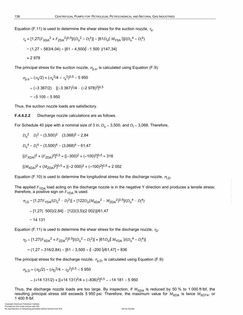
136 CENTRIFUGAL PUMPS FOR PETROLEUM, PETROCHEMICAL AND NATURAL GAS INDUSTRIES
Equation (F.11) is used to determine the shear stress for the suction nozzle, s.
s [1,27(FXSA2 FZSA
2)0,5]/(Do2 Di
2)] [61Do( MYSA )]/(Do4 Di
4)
(1,27 583/4,04) [61 4,500( 1 500 )/147,34]
2 978
The principal stress for the suction nozzle, p,s, is calculated using Equation (F.9):
p,s ( s/2) ( s2/4 s
2)0,5 5 950
( 3 367/2) [( 3 367)2/4 ( 2 978)2]0,5
5 105 5 950
Thus, the suction nozzle loads are satisfactory.
F.4.4.2.2 Discharge nozzle calculations are as follows.
For Schedule 40 pipe with a nominal size of 3 in, Do 3,500, and Di 3,068. Therefore,
Do2 Di
2 (3,500)2 (3,068)2 2,84
Do4 Di
4 (3,500)4 (3,068)4 61,47
[(FXDA)2 (FZDA)2]0,5 [( 300)2 ( 100)2]0,5 316
[(MXDA)2 (MZDA)2]0,5 [( 2 000)2 ( 100)2]0,5 2 002
Equation (F.10) is used to determine the longitudinal stress for the discharge nozzle, l,D.
The applied FYDA load acting on the discharge nozzle is in the negative Y direction and produces a tensile stress; therefore, a positive sign on FYDA is used.
l,D [1,27FYDA/(Do2 Di
2)] [122Do(MXDA2 MZDA
2)0,5]/(Do4 Di
4)
[1,27( 500)/2,84] [122(3,5)(2 002)]/61,47
14 131
Equation (F.11) is used to determine the shear stress for the discharge nozzle, D.
D [1,27(FXDA2 FZDA
2)0,5]/(Do2 Di
2)] [61Do( MYDA )/(Do4 Di
4)]
(1,27 316/2,84) [61 3,500 ( 200 )/61,47] 836
The principal stress for the discharge nozzle, p,D, is calculated using Equation (F.9):
p,D ( D/2) ( D2/4 D
2)0,5 5 950
( 14 131/2) [( 14 131)2/4 ( 836)2]0,5 14 181 5 950
Thus, the discharge nozzle loads are too large. By inspection, if MXDA is reduced by 50 % to 1 000 ft·lbf, the resulting principal stress still exceeds 5 950 psi. Therefore, the maximum value for MXDA is twice MXDT4, or 1 400 ft·lbf.
Copyright American Petroleum Institute Provided by IHS under license with API
Not for ResaleNo reproduction or networking permitted without license from IHS
--`,,```,,,,````-`-`,,`,,`,`,,`---
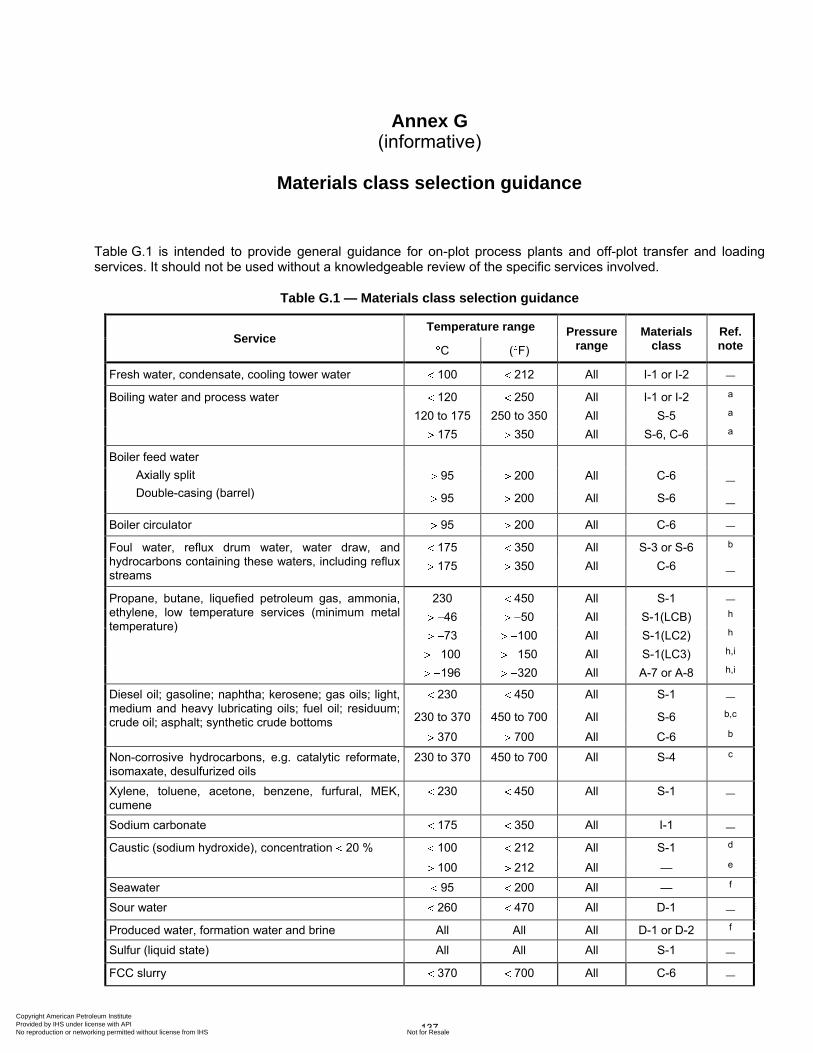
137
Annex G (informative)
Materials class selection guidance
Table G.1 is intended to provide general guidance for on-plot process plants and off-plot transfer and loading services. It should not be used without a knowledgeable review of the specific services involved.
Table G.1 — Materials class selection guidance
Service Temperature range Pressure
range Materials
class Ref. note C ( F)
Fresh water, condensate, cooling tower water 100 212 All I-1 or I-2 —
Boiling water and process water 120 250 All I-1 or I-2 a
120 to 175 250 to 350 All S-5 a
175 350 All S-6, C-6 a
Boiler feed water
Axially split
Double-casing (barrel)
95 200 All C-6 —
95 200 All S-6 —
Boiler circulator 95 200 All C-6 —
Foul water, reflux drum water, water draw, and hydrocarbons containing these waters, including reflux streams
175 350 All S-3 or S-6 b
175 350 All C-6 —
Propane, butane, liquefied petroleum gas, ammonia, ethylene, low temperature services (minimum metal temperature)
230 450 All S-1 —
46 50 All S-1(LCB) h
73 100 All S-1(LC2) h
100 150 All S-1(LC3) h,i
196 320 All A-7 or A-8 h,i
Diesel oil; gasoline; naphtha; kerosene; gas oils; light,
medium and heavy lubricating oils; fuel oil; residuum; crude oil; asphalt; synthetic crude bottoms
230 450 All S-1 —
230 to 370 450 to 700 All S-6 b,c
370 700 All C-6 b
Non-corrosive hydrocarbons, e.g. catalytic reformate, isomaxate, desulfurized oils
230 to 370 450 to 700 All S-4 c
Xylene, toluene, acetone, benzene, furfural, MEK, cumene
230 450 All S-1 —
Sodium carbonate 175 350 All I-1 —
Caustic (sodium hydroxide), concentration 20 % 100 212 All S-1 d
100 212 All — e
Seawater 95 200 All — f
Sour water 260 470 All D-1 —
Produced water, formation water and brine All All All D-1 or D-2 f
Sulfur (liquid state) All All All S-1 —
FCC slurry 370 700 All C-6 —
Copyright American Petroleum Institute Provided by IHS under license with API
Not for ResaleNo reproduction or networking permitted without license from IHS
--`,,```,,,,````-`-`,,`,,`,`,,`---
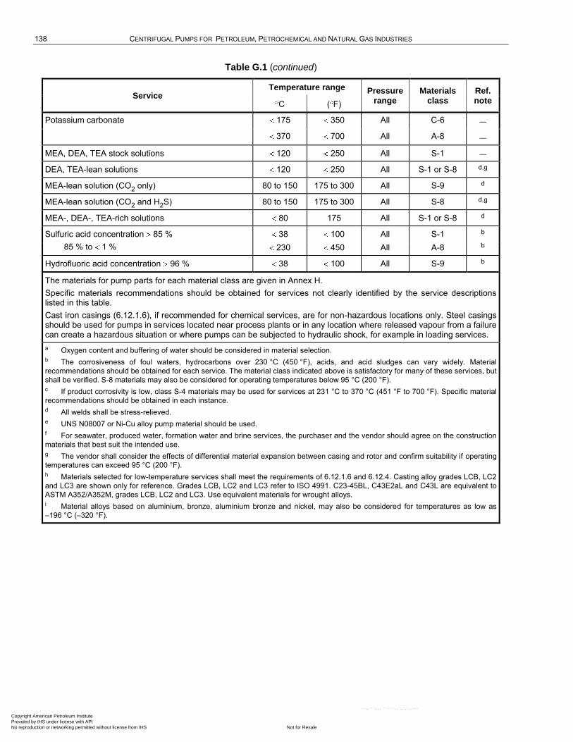
138 CENTRIFUGAL PUMPS FOR PETROLEUM, PETROCHEMICAL AND NATURAL GAS INDUSTRIES
Table G.1 (continued)
Service Temperature range Pressure
range Materials
class Ref. note C ( F)
Potassium carbonate 175 350 All C-6 —
370 700 All A-8 —
MEA, DEA, TEA stock solutions 120 250 All S-1 —
DEA, TEA-lean solutions 120 250 All S-1 or S-8 d,g
MEA-lean solution (CO2 only) 80 to 150 175 to 300 All S-9 d
MEA-lean solution (CO2 and H2S) 80 to 150 175 to 300 All S-8 d,g
MEA-, DEA-, TEA-rich solutions 80 175 All S-1 or S-8 d
Sulfuric acid concentration 85 %
85 % to 1 %
38 100 All S-1 b
230 450 All A-8 b
Hydrofluoric acid concentration 96 % 38 100 All S-9 b
The materials for pump parts for each material class are given in Annex H.
Specific materials recommendations should be obtained for services not clearly identified by the service descriptions listed in this table.
Cast iron casings (6.12.1.6), if recommended for chemical services, are for non-hazardous locations only. Steel casings should be used for pumps in services located near process plants or in any location where released vapour from a failure can create a hazardous situation or where pumps can be subjected to hydraulic shock, for example in loading services.
a Oxygen content and buffering of water should be considered in material selection.
b The corrosiveness of foul waters, hydrocarbons over 230 °C (450 °F), acids, and acid sludges can vary widely. Material
recommendations should be obtained for each service. The material class indicated above is satisfactory for many of these services, but
shall be verified. S-8 materials may also be considered for operating temperatures below 95 °C (200 °F).
c If product corrosivity is low, class S-4 materials may be used for services at 231 °C to 370 °C (451 °F to 700 °F). Specific material
recommendations should be obtained in each instance.
d All welds shall be stress-relieved.
e UNS N08007 or Ni-Cu alloy pump material should be used.
f For seawater, produced water, formation water and brine services, the purchaser and the vendor should agree on the construction
materials that best suit the intended use.
g The vendor shall consider the effects of differential material expansion between casing and rotor and confirm suitability if operating
temperatures can exceed 95 °C (200 °F).
h Materials selected for low-temperature services shall meet the requirements of 6.12.1.6 and 6.12.4. Casting alloy grades LCB, LC2
and LC3 are shown only for reference. Grades LCB, LC2 and LC3 refer to ISO 4991. C23-45BL, C43E2aL and C43L are equivalent to
ASTM A352/A352M, grades LCB, LC2 and LC3. Use equivalent materials for wrought alloys.
i Material alloys based on aluminium, bronze, aluminium bronze and nickel, may also be considered for temperatures as low as
–196 °C (–320 °F).
Copyright American Petroleum Institute Provided by IHS under license with API
Not for ResaleNo reproduction or networking permitted without license from IHS
--`,,```,,,,````-`-`,,`,,`,`,,`---
139
Annex H (normative)
Materials and material specifications for pump parts
Table H.1 lists material classes for the purchaser to select (see 6.12.1.2).
Tables H.2, H.3, and H.4 may be used for guidance regarding materials specifications. If these tables are used, it should not be assumed that the material specifications are acceptable without taking full account of the service in which they will be applied. Table H.2 lists corresponding international materials that may be considered acceptable. These materials represent family/type and grade only. The final required condition or hardness level (where appropriate) is not specified. These materials might not be interchangeable for all applications.
Copyright American Petroleum Institute Provided by IHS under license with API
Not for ResaleNo reproduction or networking permitted without license from IHS
--`,,```,,,,````-`-`,,`,,`,`,,`---
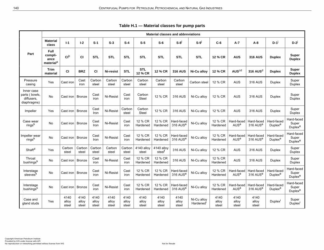
140 CENTRIFUGAL PUMPS FOR PETROLEUM, PETROCHEMICAL AND NATURAL GAS INDUSTRIES
Table H.1 — Material classes for pump parts
Part
Material classes and abbreviations
Material
class I-1 I-2 S-1 S-3 S-4 S-5 S-6 S-8l S-9l C-6 A-7 A-8 D-1j D-2j
Full
compli-
ance
materiala
CIb CI STL STL STL STL STL STL STL 12 % CR AUS 316 AUS Duplex Super
Duplex
Trim
material CI BRZ CI Ni-resist STL
STL
12 % CR 12 % CR 316 AUS Ni-Cu alloy 12 % CR AUScd 316 AUSd Duplex
Super
Duplex
Pressure
casing Yes Cast iron
Cast
iron
Carbon
steel
Carbon
steel
Carbon
steel
Carbon
steel
Carbon
steel
Carbon
steel Carbon steel 12 % CR AUS 316 AUS Duplex
Super
Duplex
Inner case
parts ( bowls,
diffusers,
diaphragms)
No Cast iron Bronze Cast
iron Ni-Resist
Cast
iron
Carbon
Steel 12 % CR 316 AUS Ni-Cu alloy 12 % CR AUS 316 AUS Duplex
Super
Duplex
Impeller Yes Cast iron Bronze Cast
Iron Ni-Resist
Carbon
steel
Carbon
Steel 12 % CR 316 AUS Ni-Cu alloy 12 % CR AUS 316 AUS Duplex
Super
Duplex
Case wear
ringsk No Cast iron Bronze
Cast
Iron Ni-Resist
Cast
iron
12 % CR
Hardened
12 % CR
Hardened
Hard-faced
316 AUSe Ni-Cu alloy
12 % CR
Hardened
Hard-faced
AUSe
Hard-faced
316 AUSe
Hard-faced
Duplexe
Hard-faced
Super
Duplexe
Impeller wear
ringsk No Cast iron Bronze
Cast
Iron Ni-Resist
Cast
iron
12 % CR
Hardened
12 % CR
Hardened
Hard-faced
316 AUSe Ni-Cu alloy
12 % CR
Hardened
Hard-faced
AUSe
Hard-faced
316 AUSe
Hard-faced
Duplexe
Hard-faced
Super
Duplexe
Shaftd Yes Carbon
steel
Carbon
steel
Carbon
steel
Carbon
steel
Carbon
steel
4140 alloy
steel
4140 alloy
steelf 316 AUS Ni-Cu alloy 12 % CR AUS 316 AUS Duplex
Super
Duplex
Throat
bushingsk No Cast iron Bronze
Cast
iron Ni-Resist
Cast
iron
12 % CR
Hardened
12 % CR
Hardened 316 AUS Ni-Cu alloy
12 % CR
Hardened AUS 316 AUS Duplex
Super
Duplex
Interstage
sleevesk No Cast iron Bronze
Cast
iron Ni-Resist
Cast
iron
12 % CR
Hardened
12 % CR
Hardened
Hard-faced
316 AUSe Ni-Cu alloy
12 % CR
Hardened
Hard-faced
AUSe
Hard-faced
316 AUSe
Hard-faced
Duplexe
Hard-faced
Super
Duplexe
Interstage
bushingsk No Cast iron Bronze
Cast
iron Ni-Resist
Cast
iron
12 % CR
Hardened
12 % CR
Hardened
Hard-faced
316 AUSe Ni-Cu alloy
12 % CR
Hardened
Hard-faced
AUSe
Hard-faced
316 AUSe
Hard-faced
Duplexe
Hard-faced
Super
Duplexe
Case and
gland studs Yes
4140
alloy
steel
4140
alloy
steel
4140
alloy
steel
4140
alloy
steel
4140
alloy
steel
4140
alloy
steel
4140
alloy
steel
4140
alloy
steel
Ni-Cu alloy
Hardenedi
4140
alloy
steel
4140
alloy
steel
4140
alloy
steel
Duplexi Super
Duplexi
Copyright American Petroleum Institute Provided by IHS under license with API
Not for ResaleNo reproduction or networking permitted without license from IHS
--`,,```,,,,````-`-`,,`,,`,`,,`---
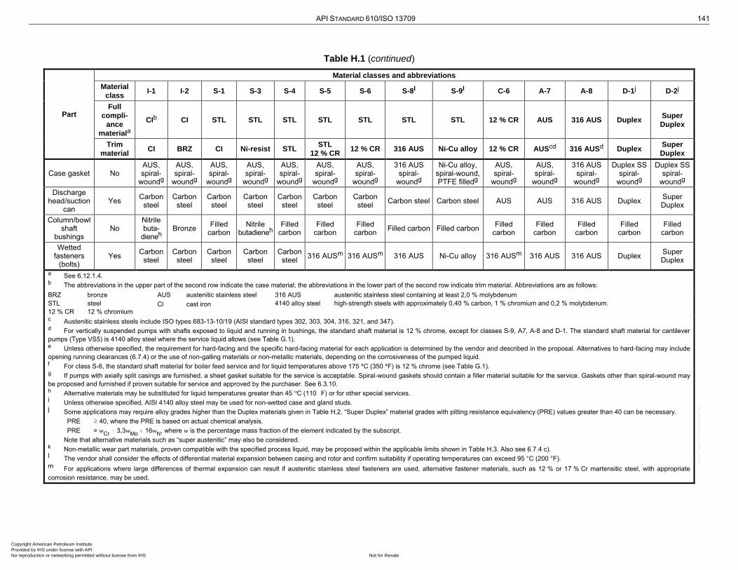
API STANDARD 610/ISO 13709 141
Table H.1 (continued)
Part
Material classes and abbreviations
Material
class I-1 I-2 S-1 S-3 S-4 S-5 S-6 S-8l S-9l C-6 A-7 A-8 D-1j D-2j
Full
compli-
ance
materiala
CIb CI STL STL STL STL STL STL STL 12 % CR AUS 316 AUS Duplex Super
Duplex
Trim
material CI BRZ CI Ni-resist STL
STL
12 % CR 12 % CR 316 AUS Ni-Cu alloy 12 % CR AUScd 316 AUSd Duplex
Super
Duplex
Case gasket No AUS, spiral-
woundg
AUS, spiral-
woundg
AUS, spiral-
woundg
AUS, spiral-
woundg
AUS, spiral-
woundg
AUS, spiral-
woundg
AUS, spiral-
woundg
316 AUS spiral-
woundg
Ni-Cu alloy, spiral-wound, PTFE filledg
AUS, spiral-
woundg
AUS, spiral-
woundg
316 AUS spiral-
woundg
Duplex SS spiral-
woundg
Duplex SS spiral-
woundg
Discharge head/suction
can Yes
Carbon steel
Carbon steel
Carbon steel
Carbon steel
Carbon steel
Carbon steel
Carbon steel
Carbon steel Carbon steel AUS AUS 316 AUS Duplex Super Duplex
Column/bowl shaft
bushings No
Nitrile buta-
dieneh Bronze
Filled carbon
Nitrile butadieneh
Filled carbon
Filled carbon
Filled carbon
Filled carbon Filled carbon Filled
carbon Filled
carbon Filled
carbon Filled
carbon Filled
carbon
Wetted fasteners
(bolts) Yes
Carbon steel
Carbon steel
Carbon steel
Carbon steel
Carbon steel
316 AUSm 316 AUSm 316 AUS Ni-Cu alloy 316 AUSm 316 AUS 316 AUS Duplex Super Duplex
a See 6.12.1.4. b The abbreviations in the upper part of the second row indicate the case material; the abbreviations in the lower part of the second row indicate trim material. Abbreviations are as follows:
BRZ bronze
STL steel
12 % CR 12 % chromium
AUS austenitic stainless steel
Cl cast iron
316 AUS austenitic stainless steel containing at least 2,0 % molybdenum
4140 alloy steel high-strength steels with approximately 0,40 % carbon, 1 % chromium and 0,2 % molybdenum.
c Austenitic stainless steels include ISO types 683-13-10/19 (AISI standard types 302, 303, 304, 316, 321, and 347). d For vertically suspended pumps with shafts exposed to liquid and running in bushings, the standard shaft material is 12 % chrome, except for classes S-9, A7, A-8 and D-1. The standard shaft material for cantilever
pumps (Type VS5) is 4140 alloy steel where the service liquid allows (see Table G.1). e Unless otherwise specified, the requirement for hard-facing and the specific hard-facing material for each application is determined by the vendor and described in the proposal. Alternatives to hard-facing may include
opening running clearances (6.7.4) or the use of non-galling materials or non-metallic materials, depending on the corrosiveness of the pumped liquid. f For class S-6, the standard shaft material for boiler feed service and for liquid temperatures above 175 C (350 F) is 12 % chrome (see Table G.1). g If pumps with axially split casings are furnished, a sheet gasket suitable for the service is acceptable. Spiral-wound gaskets should contain a filler material suitable for the service. Gaskets other than spiral-wound may
be proposed and furnished if proven suitable for service and approved by the purchaser. See 6.3.10. h Alternative materials may be substituted for liquid temperatures greater than 45 C (110 F) or for other special services. i Unless otherwise specified, AISI 4140 alloy steel may be used for non-wetted case and gland studs. j Some applications may require alloy grades higher than the Duplex materials given in Table H.2. ―Super Duplex‖ material grades with pitting resistance equivalency (PRE) values greater than 40 can be necessary.
PRE ≥ 40, where the PRE is based on actual chemical analysis.
PRE = wCr
3,3wMo
16wN
, where w is the percentage mass fraction of the element indicated by the subscript.
Note that alternative materials such as “super austenitic‖ may also be considered. k Non-metallic wear part materials, proven compatible with the specified process liquid, may be proposed within the applicable limits shown in Table H.3. Also see 6.7.4 c). l The vendor shall consider the effects of differential material expansion between casing and rotor and confirm suitability if operating temperatures can exceed 95 °C (200 °F). m For applications where large differences of thermal expansion can result if austenitic stainless steel fasteners are used, alternative fastener materials, such as 12 % or 17 % Cr martensitic steel, with appropriate
corrosion resistance, may be used.
Copyright American Petroleum Institute Provided by IHS under license with API
Not for ResaleNo reproduction or networking permitted without license from IHS
--`,,```,,,,````-`-`,,`,,`,`,,`---
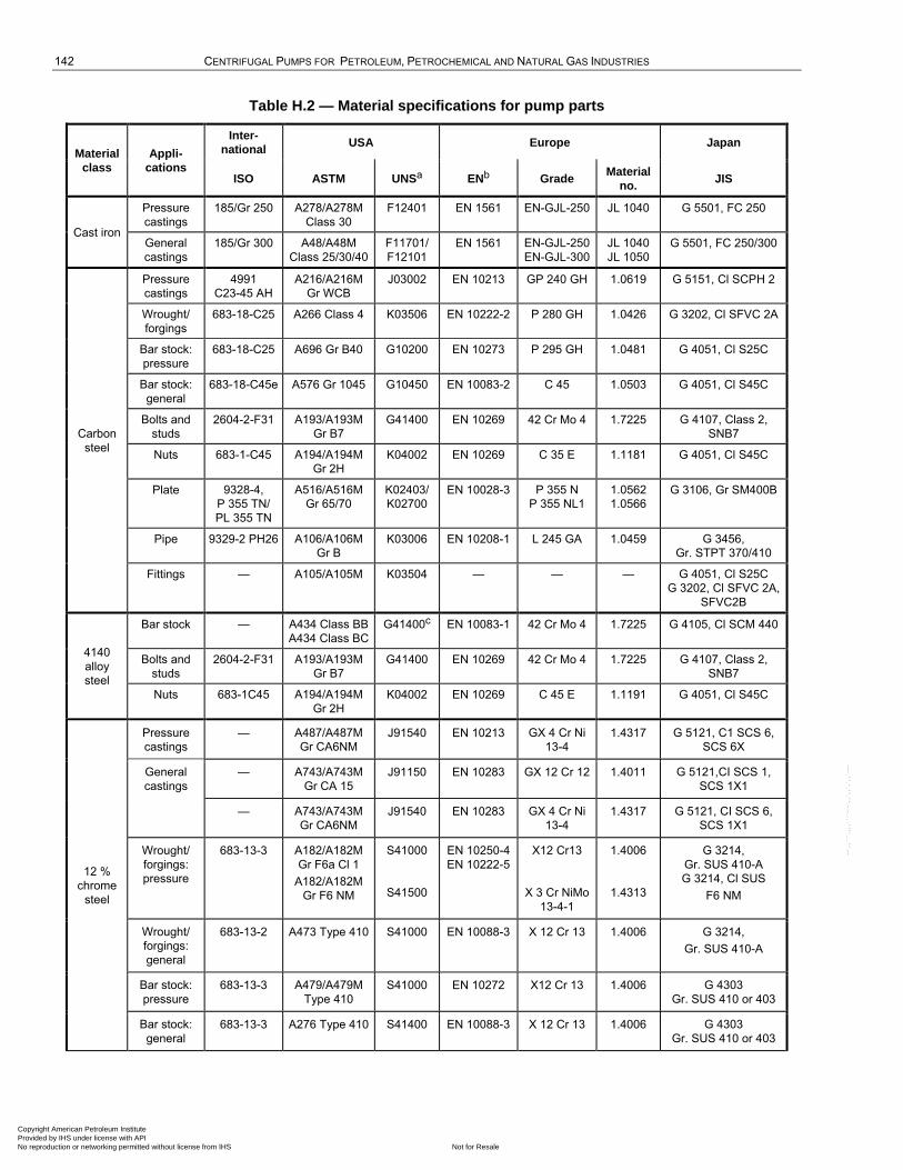
142 CENTRIFUGAL PUMPS FOR PETROLEUM, PETROCHEMICAL AND NATURAL GAS INDUSTRIES
Table H.2 — Material specifications for pump parts
Material
class
Appli-
cations
Inter-
national USA Europe Japan
ISO ASTM UNSa ENb Grade Material
no. JIS
Cast iron
Pressure
castings
185/Gr 250 A278/A278M
Class 30
F12401 EN 1561 EN-GJL-250 JL 1040 G 5501, FC 250
General
castings
185/Gr 300 A48/A48M
Class 25/30/40
F11701/
F12101
EN 1561 EN-GJL-250
EN-GJL-300
JL 1040
JL 1050
G 5501, FC 250/300
Carbon
steel
Pressure
castings
4991
C23-45 AH
A216/A216M
Gr WCB
J03002 EN 10213 GP 240 GH 1.0619 G 5151, Cl SCPH 2
Wrought/
forgings
683-18-C25 A266 Class 4 K03506 EN 10222-2 P 280 GH 1.0426 G 3202, Cl SFVC 2A
Bar stock:
pressure
683-18-C25 A696 Gr B40 G10200 EN 10273 P 295 GH 1.0481 G 4051, Cl S25C
Bar stock:
general
683-18-C45e A576 Gr 1045 G10450 EN 10083-2 C 45 1.0503 G 4051, Cl S45C
Bolts and
studs
2604-2-F31 A193/A193M
Gr B7
G41400 EN 10269 42 Cr Mo 4 1.7225 G 4107, Class 2,
SNB7
Nuts 683-1-C45 A194/A194M
Gr 2H
K04002 EN 10269 C 35 E 1.1181 G 4051, Cl S45C
Plate 9328-4,
P 355 TN/
PL 355 TN
A516/A516M
Gr 65/70
K02403/
K02700
EN 10028-3 P 355 N
P 355 NL1
1.0562
1.0566
G 3106, Gr SM400B
Pipe 9329-2 PH26 A106/A106M
Gr B
K03006 EN 10208-1 L 245 GA 1.0459 G 3456,
Gr. STPT 370/410
Fittings — A105/A105M K03504 — — — G 4051, Cl S25C
G 3202, Cl SFVC 2A,
SFVC2B
4140
alloy
steel
Bar stock — A434 Class BB
A434 Class BC
G41400c EN 10083-1 42 Cr Mo 4 1.7225 G 4105, Cl SCM 440
Bolts and
studs
2604-2-F31 A193/A193M
Gr B7
G41400 EN 10269 42 Cr Mo 4 1.7225 G 4107, Class 2,
SNB7
Nuts 683-1C45 A194/A194M
Gr 2H
K04002 EN 10269 C 45 E 1.1191 G 4051, Cl S45C
12 %
chrome
steel
Pressure
castings
— A487/A487M
Gr CA6NM
J91540 EN 10213 GX 4 Cr Ni
13-4
1.4317 G 5121, C1 SCS 6,
SCS 6X
General
castings
— A743/A743M
Gr CA 15
J91150 EN 10283 GX 12 Cr 12 1.4011 G 5121,CI SCS 1,
SCS 1X1
— A743/A743M
Gr CA6NM
J91540 EN 10283 GX 4 Cr Ni
13-4
1.4317 G 5121, CI SCS 6,
SCS 1X1
Wrought/
forgings:
pressure
683-13-3 A182/A182M
Gr F6a Cl 1
A182/A182M
Gr F6 NM
S41000
S41500
EN 10250-4
EN 10222-5
X12 Cr13
X 3 Cr NiMo
13-4-1
1.4006
1.4313
G 3214,
Gr. SUS 410-A
G 3214, Cl SUS
F6 NM
Wrought/
forgings:
general
683-13-2 A473 Type 410 S41000 EN 10088-3 X 12 Cr 13 1.4006 G 3214,
Gr. SUS 410-A
Bar stock:
pressure
683-13-3 A479/A479M
Type 410
S41000 EN 10272 X12 Cr 13 1.4006 G 4303
Gr. SUS 410 or 403
Bar stock:
general
683-13-3 A276 Type 410 S41400 EN 10088-3 X 12 Cr 13 1.4006 G 4303
Gr. SUS 410 or 403
Copyright American Petroleum Institute Provided by IHS under license with API
Not for ResaleNo reproduction or networking permitted without license from IHS
--`,,```,,,,````-`-`,,`,,`,`,,`---
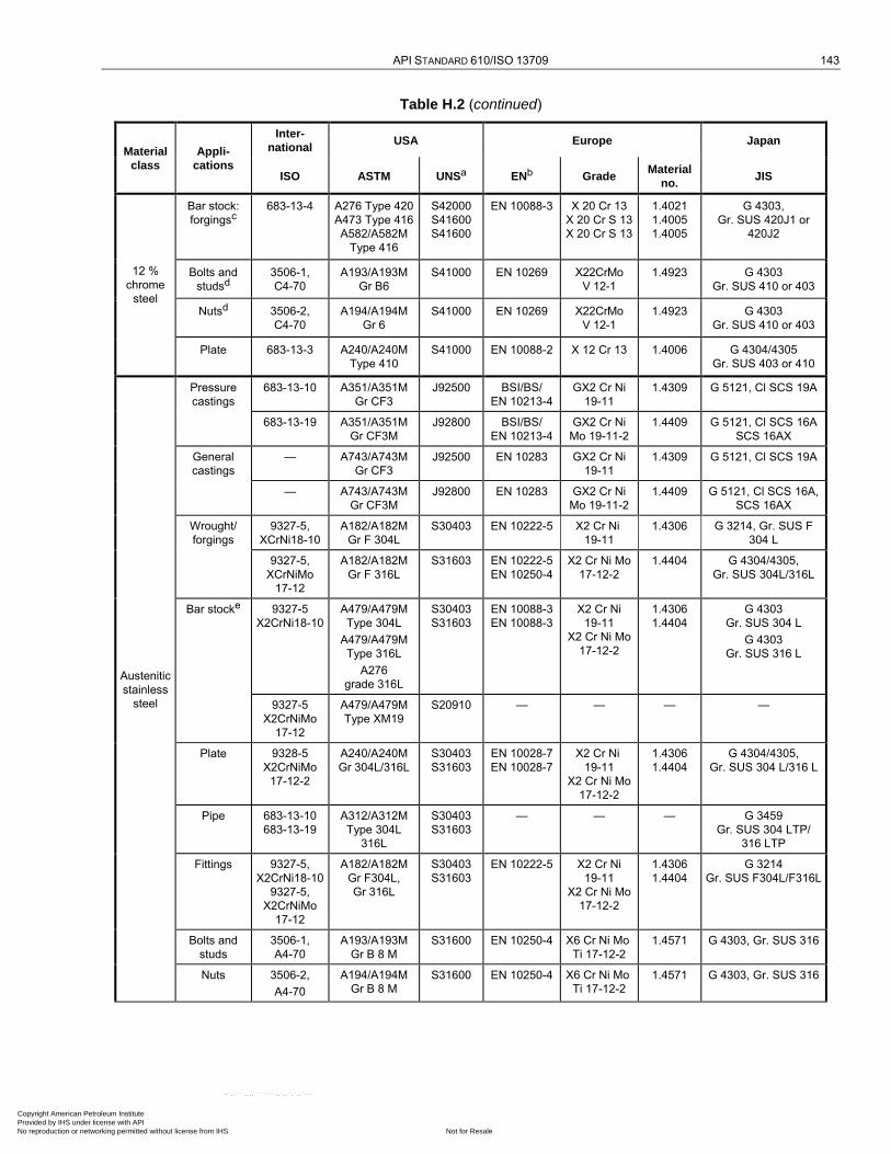
API STANDARD 610/ISO 13709 143
Table H.2 (continued)
Material
class
Appli-
cations
Inter-
national USA Europe Japan
ISO ASTM UNSa ENb Grade Material
no. JIS
12 %
chrome
steel
Bar stock:
forgingsc
683-13-4 A276 Type 420
A473 Type 416
A582/A582M
Type 416
S42000
S41600
S41600
EN 10088-3 X 20 Cr 13
X 20 Cr S 13
X 20 Cr S 13
1.4021
1.4005
1.4005
G 4303,
Gr. SUS 420J1 or
420J2
Bolts and
studsd
3506-1,
C4-70
A193/A193M
Gr B6
S41000 EN 10269 X22CrMo
V 12-1
1.4923 G 4303
Gr. SUS 410 or 403
Nutsd 3506-2,
C4-70
A194/A194M
Gr 6
S41000 EN 10269 X22CrMo
V 12-1
1.4923 G 4303
Gr. SUS 410 or 403
Plate 683-13-3 A240/A240M
Type 410
S41000 EN 10088-2 X 12 Cr 13 1.4006 G 4304/4305
Gr. SUS 403 or 410
Austenitic
stainless
steel
Pressure
castings
683-13-10 A351/A351M
Gr CF3
J92500 BSI/BS/
EN 10213-4
GX2 Cr Ni
19-11
1.4309 G 5121, Cl SCS 19A
683-13-19 A351/A351M
Gr CF3M
J92800 BSI/BS/
EN 10213-4
GX2 Cr Ni
Mo 19-11-2
1.4409 G 5121, Cl SCS 16A
SCS 16AX
General
castings
— A743/A743M
Gr CF3
J92500 EN 10283 GX2 Cr Ni
19-11
1.4309 G 5121, Cl SCS 19A
— A743/A743M
Gr CF3M
J92800 EN 10283 GX2 Cr Ni
Mo 19-11-2
1.4409 G 5121, Cl SCS 16A,
SCS 16AX
Wrought/
forgings
9327-5,
XCrNi18-10
A182/A182M
Gr F 304L
S30403 EN 10222-5 X2 Cr Ni
19-11
1.4306 G 3214, Gr. SUS F
304 L
9327-5,
XCrNiMo
17-12
A182/A182M
Gr F 316L
S31603 EN 10222-5
EN 10250-4
X2 Cr Ni Mo
17-12-2
1.4404 G 4304/4305,
Gr. SUS 304L/316L
Bar stocke 9327-5
X2CrNi18-10
A479/A479M
Type 304L
A479/A479M
Type 316L
A276
grade 316L
S30403
S31603
EN 10088-3
EN 10088-3
X2 Cr Ni
19-11
X2 Cr Ni Mo
17-12-2
1.4306
1.4404
G 4303
Gr. SUS 304 L
G 4303
Gr. SUS 316 L
9327-5
X2CrNiMo
17-12
A479/A479M
Type XM19
S20910 — — — —
Plate 9328-5
X2CrNiMo
17-12-2
A240/A240M
Gr 304L/316L
S30403
S31603
EN 10028-7
EN 10028-7
X2 Cr Ni
19-11
X2 Cr Ni Mo
17-12-2
1.4306
1.4404
G 4304/4305,
Gr. SUS 304 L/316 L
Pipe 683-13-10
683-13-19
A312/A312M
Type 304L
316L
S30403
S31603
— — — G 3459
Gr. SUS 304 LTP/
316 LTP
Fittings 9327-5,
X2CrNi18-10
9327-5,
X2CrNiMo
17-12
A182/A182M
Gr F304L,
Gr 316L
S30403
S31603
EN 10222-5 X2 Cr Ni
19-11
X2 Cr Ni Mo
17-12-2
1.4306
1.4404
G 3214
Gr. SUS F304L/F316L
Bolts and
studs
3506-1,
A4-70
A193/A193M
Gr B 8 M
S31600 EN 10250-4 X6 Cr Ni Mo
Ti 17-12-2
1.4571 G 4303, Gr. SUS 316
Nuts 3506-2,
A4-70
A194/A194M
Gr B 8 M
S31600 EN 10250-4 X6 Cr Ni Mo
Ti 17-12-2
1.4571 G 4303, Gr. SUS 316
Copyright American Petroleum Institute Provided by IHS under license with API
Not for ResaleNo reproduction or networking permitted without license from IHS
--`,,```,,,,````-`-`,,`,,`,`,,`---
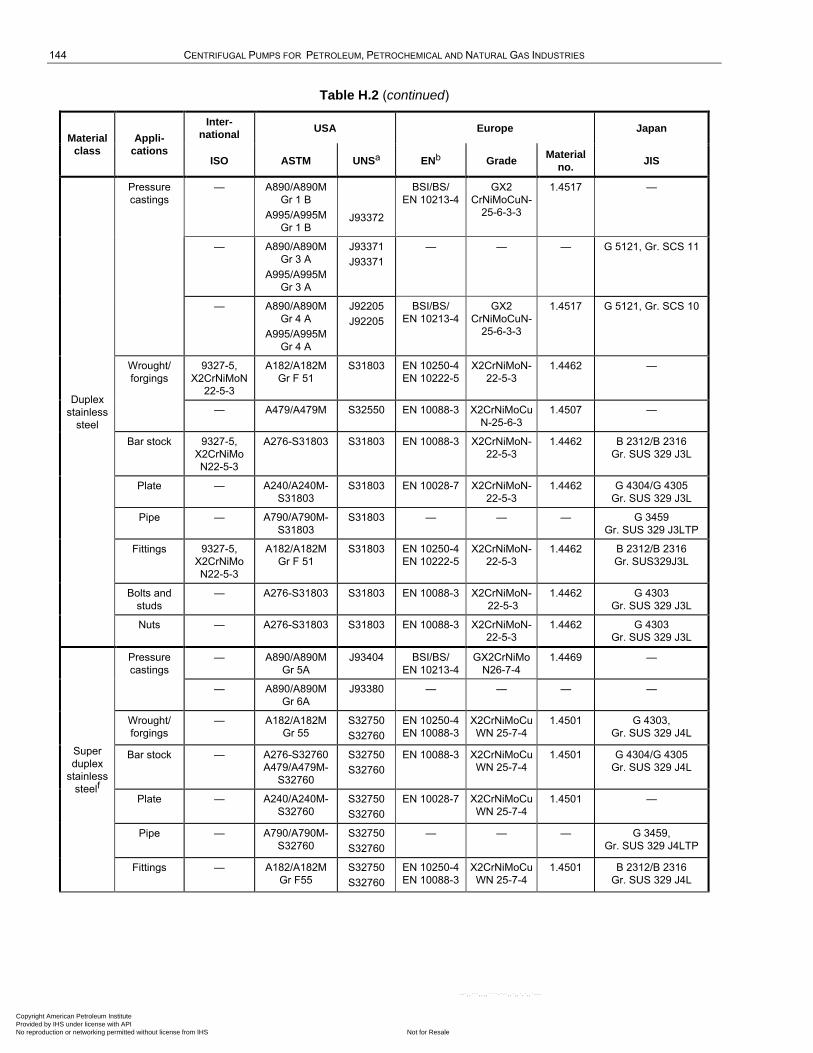
144 CENTRIFUGAL PUMPS FOR PETROLEUM, PETROCHEMICAL AND NATURAL GAS INDUSTRIES
Table H.2 (continued)
Material
class
Appli-
cations
Inter-
national USA Europe Japan
ISO ASTM UNSa ENb Grade Material
no. JIS
Duplex
stainless
steel
Pressure
castings
— A890/A890M
Gr 1 B
A995/A995M
Gr 1 B
J93372
BSI/BS/
EN 10213-4
GX2
CrNiMoCuN-
25-6-3-3
1.4517 —
— A890/A890M
Gr 3 A
A995/A995M
Gr 3 A
J93371
J93371
— — — G 5121, Gr. SCS 11
— A890/A890M
Gr 4 A
A995/A995M
Gr 4 A
J92205
J92205
BSI/BS/
EN 10213-4
GX2
CrNiMoCuN-
25-6-3-3
1.4517 G 5121, Gr. SCS 10
Wrought/
forgings
9327-5,
X2CrNiMoN
22-5-3
A182/A182M
Gr F 51
S31803 EN 10250-4
EN 10222-5
X2CrNiMoN-
22-5-3
1.4462 —
— A479/A479M S32550 EN 10088-3 X2CrNiMoCu
N-25-6-3
1.4507 —
Bar stock 9327-5,
X2CrNiMo
N22-5-3
A276-S31803 S31803 EN 10088-3 X2CrNiMoN-
22-5-3
1.4462 B 2312/B 2316
Gr. SUS 329 J3L
Plate — A240/A240M-
S31803
S31803 EN 10028-7 X2CrNiMoN-
22-5-3
1.4462 G 4304/G 4305
Gr. SUS 329 J3L
Pipe — A790/A790M-
S31803
S31803 — — — G 3459
Gr. SUS 329 J3LTP
Fittings 9327-5,
X2CrNiMo
N22-5-3
A182/A182M
Gr F 51
S31803 EN 10250-4
EN 10222-5
X2CrNiMoN-
22-5-3
1.4462 B 2312/B 2316
Gr. SUS329J3L
Bolts and
studs
— A276-S31803 S31803 EN 10088-3 X2CrNiMoN-
22-5-3
1.4462 G 4303
Gr. SUS 329 J3L
Nuts — A276-S31803 S31803 EN 10088-3 X2CrNiMoN-
22-5-3
1.4462 G 4303
Gr. SUS 329 J3L
Super
duplex
stainless
steelf
Pressure
castings
— A890/A890M
Gr 5A
J93404 BSI/BS/
EN 10213-4
GX2CrNiMo
N26-7-4
1.4469 —
— A890/A890M
Gr 6A
J93380 — — — —
Wrought/
forgings
— A182/A182M
Gr 55
S32750
S32760
EN 10250-4
EN 10088-3
X2CrNiMoCu
WN 25-7-4
1.4501 G 4303,
Gr. SUS 329 J4L
Bar stock — A276-S32760
A479/A479M-
S32760
S32750
S32760
EN 10088-3 X2CrNiMoCu
WN 25-7-4
1.4501 G 4304/G 4305
Gr. SUS 329 J4L
Plate — A240/A240M-
S32760
S32750
S32760
EN 10028-7 X2CrNiMoCu
WN 25-7-4
1.4501 —
Pipe — A790/A790M-
S32760
S32750
S32760
— — — G 3459,
Gr. SUS 329 J4LTP
Fittings — A182/A182M
Gr F55
S32750
S32760
EN 10250-4
EN 10088-3
X2CrNiMoCu
WN 25-7-4
1.4501 B 2312/B 2316
Gr. SUS 329 J4L
Copyright American Petroleum Institute Provided by IHS under license with API
Not for ResaleNo reproduction or networking permitted without license from IHS
--`,,```,,,,````-`-`,,`,,`,`,,`---

API STANDARD 610/ISO 13709 145
Table H.2 (continued)
Material
class
Appli-
cations
Inter-
national USA Europe Japan
ISO ASTM UNSa ENb Grade Material
no. JIS
Super
duplex
stainless
steelf
Bolts and
studs
— A276-S32760 S32750
S32760
EN 10088-3 X2CrNiMoCu
WN 25-7-4
1.4501 G 4303
Gr. SUS 329 J4L
Nuts — A276-S32760 S32750
S32760
EN 10088-3 X2CrNiMoCu
WN 25-7-4
1.4501 G 4303
Gr. SUS 329 J4L
a UNS (unified numbering system) designation for chemistry only.
b Where EN standards do not yet exist, European national standards are available, e.g. AFNOR, BS, DIN, etc.
c Do not use for shafts in the hardened condition (over 302 HB).
d Special, normally use 4140 alloy steel.
e For shafts, standard grades of austenitic stainless steel may be substituted in place of low-carbon (L) grades.
f Super Duplex stainless steel classified with pitting resistance equivalent (PRE) number greater than or equal to 40:
PRE = wCr 3,3wMo 16wN, where w is the percentage mass fraction of the element indicated by the subscript.
Table H.3 — Non-metallic wear part materials
Material
Temperature limits °C (°F)
Limiting pressure differential per wear part linear measure
of 25 mm (1,0 in) kPa (bar; psi)
Application
min. max.
Polyether ether ketone (PEEK)
Chopped-carbon-fibre filled
–30 (–20) 135 (275) 2 000 (20; 300) Stationary parts
Polyether ether ketone (PEEK)
Continuous-carbon-fibre wound
–30 (–20) 230 (450) 3 500 (35; 500), or
14 000 (140; 2 000) if suitably supported
Stationary or rotating
PFA/CF reinforced composite
20 % mass fraction random X-Y oriented carbon-fibre
–46 (–50) 230 (450) 2 000 (20; 300) Stationary parts
Carbon graphite
Resin-impregnated
–50 (–55)
285 (550)
2 000 (20; 300)
Stationary parts
Babbitt-impregnated –100 (–150) 150 (300) 2 750 (27,5; 400)
Nickel-impregnated –195 (–320) 400 (750) 3 500 (35; 500)
Copper-impregnated –100 (–150)
Non-metallic wear part materials that are proven compatible with the specified process liquid may be proposed within the above limits.
See 6.7.4 c).
Such materials may be selected as wear components for mating against a suitably selected metallic component such as hardened 12 %
Cr steel or hard-faced austenitic stainless steel. Materials may be used beyond these limits if proven application experience can be
provided, and if approved by the purchaser.
Copyright American Petroleum Institute Provided by IHS under license with API
Not for ResaleNo reproduction or networking permitted without license from IHS
--`,,```,,,,````-`-`,,`,,`,`,,`---
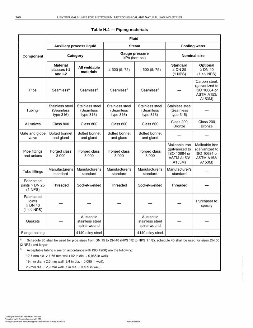
146 CENTRIFUGAL PUMPS FOR PETROLEUM, PETROCHEMICAL AND NATURAL GAS INDUSTRIES
Table H.4 — Piping materials
Component
Fluid
Auxiliary process liquid Steam Cooling water
Category Gauge pressure
kPa (bar; psi) Nominal size
Material classes I-1
and I-2
All weldable materials
≤ 500 (5; 75) 500 (5; 75) Standard ≤ DN 25 (1 NPS)
Optional ≥ DN 40
(1 1/2 NPS)
Pipe Seamlessa Seamlessa Seamlessa Seamlessa —
Carbon steel, (galvanized to ISO 10684 or ASTM A153/
A153M)
Tubingb Stainless steel
(Seamless type 316)
Stainless steel (Seamless type 316)
Stainless steel (Seamless type 316)
Stainless steel (Seamless type 316)
Stainless steel (Seamless type 316)
—
All valves Class 800 Class 800 Class 800 Class 800 Class 200
Bronze Class 200
Bronze
Gate and globe valve
Bolted bonnet and gland
Bolted bonnet and gland
Bolted bonnet and gland
Bolted bonnet and gland
— —
Pipe fittings and unions
Forged class 3 000
Forged class 3 000
Forged class 3 000
Forged class 3 000
Malleable iron (galvanized to ISO 10684 or ASTM A153/
A153M)
Malleable iron (galvanized to ISO 10684 or ASTM A153/
A153M)
Tube fittings Manufacturer's
standard Manufacturer's
standard Manufacturer's
standard Manufacturer's
standard Manufacturer's
standard —
Fabricated joints ≤ DN 25
(1 NPS) Threaded Socket-welded Threaded Socket-welded Threaded —
Fabricated joints
≥ DN 40 (1 1/2 NPS)
— — — — — Purchaser to
specify
Gaskets — Austenitic
stainless steel spiral-wound
_ Austenitic
stainless steel spiral-wound
— —
Flange bolting — 4140 alloy steel — 4140 alloy steel — —
a Schedule 80 shall be used for pipe sizes from DN 15 to DN 40 (NPS 1/2 to NPS 1 1/2); schedule 40 shall be used for sizes DN 50
(2 NPS) and larger.
b Acceptable tubing sizes (in accordance with ISO 4200) are the following:
12,7 mm dia. 1,66 mm wall (1/2 in dia. 0,065 in wall);
19 mm dia. 2,6 mm wall (3/4 in dia. 0,095 in wall);
25 mm dia. 2,9 mm wall (1 in dia. 0,109 in wall).
Copyright American Petroleum Institute Provided by IHS under license with API
Not for ResaleNo reproduction or networking permitted without license from IHS
--`,,```,,,,````-`-`,,`,,`,`,,`---

147
Annex I (normative)
Lateral analysis
I.1 Lateral analysis
I.1.1 General
If a lateral analysis is required (see 9.2.4.1), the method and assessment of results shall be as specified in I.1.2 through I.1.5. Table I.1 illustrates the analysis process. The method and assessment specified are peculiar to horizontal-axis liquid-handling turbomachines.
Table I.1 — Rotor lateral analysis logic diagram
Step If… then…
1 the pump and conditions of service are identical or similar to an existing pump with a proven operating record,
analysis is not needed.
2 the rotor is classically stiff (6.9.1.2), analysis is not needed.
3 neither 1 nor 2 is true, analysis is required.
I.1.2 Natural frequencies
The report shall state the following:
a) the rotor's first, second and third ―dry‖ bending natural frequencies (see 6.9.1.2);
NOTE 1 The ―dry‖ bending natural frequencies serve as useful reference points for subsequent analysis of the damped natural frequencies.
NOTE 2 Usual design practice is to investigate overhung modes, coupling and thrust collar, and set their first bending natural frequency at separation margin at least 20 % above the highest potential excitation frequency (based on maximum continuous speed) before carrying out lateral analysis of the rotor.
b) all the rotor's damped natural frequencies within the frequency range zero to 2,2 times maximum continuous speed, which shall be calculated for the speed range 25 % to 125 % of rated, taking account of the following:
1) stiffness and damping at the following internal running clearances at the expected temperature:
as-new clearances, with water,
as-new clearances, with the pumped liquid,
2 (two times) the as-new clearances, with the pumped liquid;
2) stiffness and damping at the shaft seals (if labyrinth type);
Copyright American Petroleum Institute Provided by IHS under license with API
Not for ResaleNo reproduction or networking permitted without license from IHS
--`,,```,,,,````-`-`,,`,,`,`,,`---

148 CENTRIFUGAL PUMPS FOR PETROLEUM, PETROCHEMICAL AND NATURAL GAS INDUSTRIES
3) stiffness and damping within the bearings for the average clearance and oil temperature. The effect of bearing stiffness and damping in pumps is generally minor in comparison to that of the internal running clearances; therefore, it is sufficient to analyse the bearings at their average clearance and oil temperature;
4) mass and stiffness of the bearing support structure;
5) inertia of the pump half-coupling hub and half the coupling spacer;
NOTE Though the higher order damped natural frequencies can be close to impeller vane passing frequency, there is no experience in liquid-handling turbomachines pointing to rotor-dynamics problems caused by such proximity. This is deemed a consequence of the complex mode shape(s), relatively low excitation energy and sufficient damping at the higher frequencies involved.
c) values or the basis of the stiffness and damping coefficients used in the calculation.
I.1.3 Separation margins and damping
For both as-new and 2 as-new clearances, the damping factor versus separation margin between any bending natural frequency and the synchronous run line shall be within the ―acceptable‖ region shown on Figure I.1. If this condition cannot be satisfied, the damped response to unbalance shall be determined (see I.1.4).
NOTE In liquid-handling turbomachines, the first assessment of a rotor's dynamic characteristics is based on damping versus separation margin, rather than amplification factor versus separation margin. Two factors account for this basis. First, the rotor's natural frequencies increase with rotative speed, a consequence of the differential pressure across internal clearances also increasing with rotative speed. On a Campbell diagram (see Figure I.2), this means that the closer separations are between the running speed and natural frequencies rather than between the running speed and the critical speeds. Because the amplification factor at the closer separations is not related to synchronous (unbalance) excitation of the rotor, it can be developed only by an approximate calculation based on the damping. Second, employing damping allows the specification of a minimum value for natural frequency to running speed ratios from 0,8 to 0,4, thereby assuring that the rotor is free from significant subsynchronous vibration.
The logarithmic decrement, , is related to the damping factor, , as given in Equation (I.1):
(2 ) (1 2)0,5 (I.1)
For up to 0,4, the approximate relationships given in Equation (I.2) between , and amplification factor, Fa, are sufficiently accurate for practical purposes:
2
1/(2 × Fa) (I.2)
In liquid-handling turbomachines, critically damped conditions correspond to the following:
≥ 0,15
≥ 0,95
Fa ≤ 3,33
NOTE 1 The values given for critically damped conditions in liquid-handling turbomachines differ from those in API standards for gas- or vapour-handling turbomachines. The difference reflects successful operating experience with liquid-handling turbomachines designed using the values in this annex.
NOTE 2 Damping of ≥ 0,08 over the range fni/frun 0,8 to 0,4 is supported by design and operating experience with liquid-handling turbomachines, which demonstrates that designs satisfying this requirement have not suffered problems with subsynchronous rotor vibration.
Copyright American Petroleum Institute Provided by IHS under license with API
Not for ResaleNo reproduction or networking permitted without license from IHS
--`,,```,,,,````-`-`,,`,,`,`,,`---
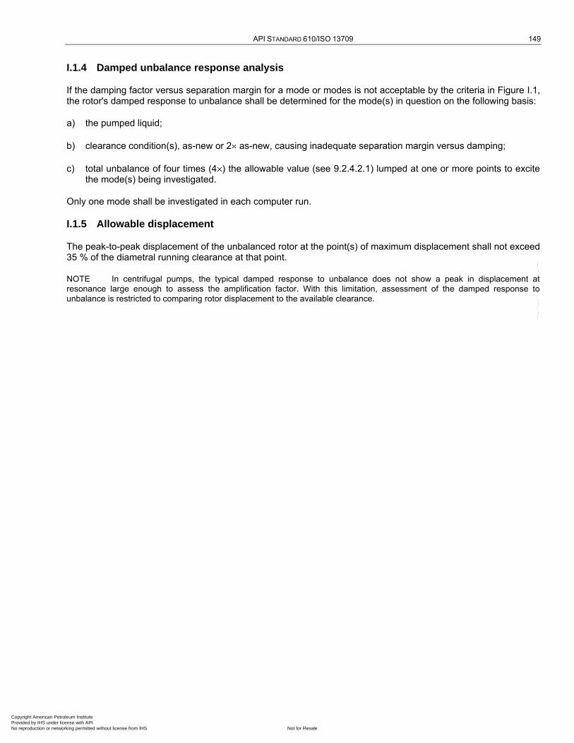
API STANDARD 610/ISO 13709 149
I.1.4 Damped unbalance response analysis
If the damping factor versus separation margin for a mode or modes is not acceptable by the criteria in Figure I.1, the rotor's damped response to unbalance shall be determined for the mode(s) in question on the following basis:
a) the pumped liquid;
b) clearance condition(s), as-new or 2 as-new, causing inadequate separation margin versus damping;
c) total unbalance of four times (4 ) the allowable value (see 9.2.4.2.1) lumped at one or more points to excite the mode(s) being investigated.
Only one mode shall be investigated in each computer run.
I.1.5 Allowable displacement
The peak-to-peak displacement of the unbalanced rotor at the point(s) of maximum displacement shall not exceed 35 % of the diametral running clearance at that point.
NOTE In centrifugal pumps, the typical damped response to unbalance does not show a peak in displacement at resonance large enough to assess the amplification factor. With this limitation, assessment of the damped response to unbalance is restricted to comparing rotor displacement to the available clearance.
Copyright American Petroleum Institute Provided by IHS under license with API
Not for ResaleNo reproduction or networking permitted without license from IHS
--`,,```,,,,````-`-`,,`,,`,`,,`---
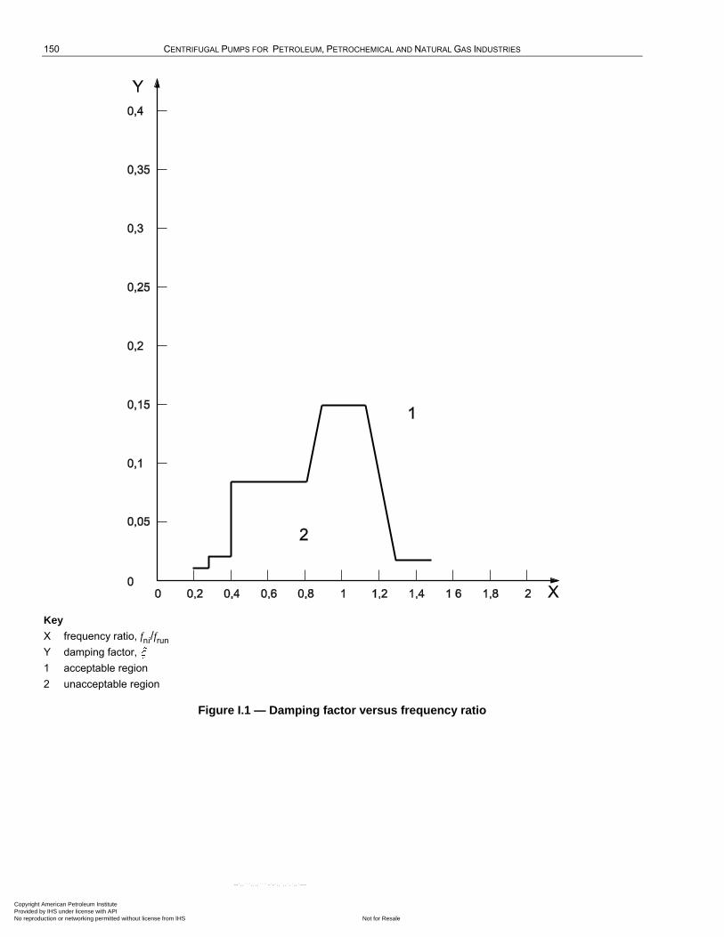
150 CENTRIFUGAL PUMPS FOR PETROLEUM, PETROCHEMICAL AND NATURAL GAS INDUSTRIES
Key
X frequency ratio, fni/frun
Y damping factor,
1 acceptable region
2 unacceptable region
Figure I.1 — Damping factor versus frequency ratio
Copyright American Petroleum Institute Provided by IHS under license with API
Not for ResaleNo reproduction or networking permitted without license from IHS
--`,,```,,,,````-`-`,,`,,`,`,,`---
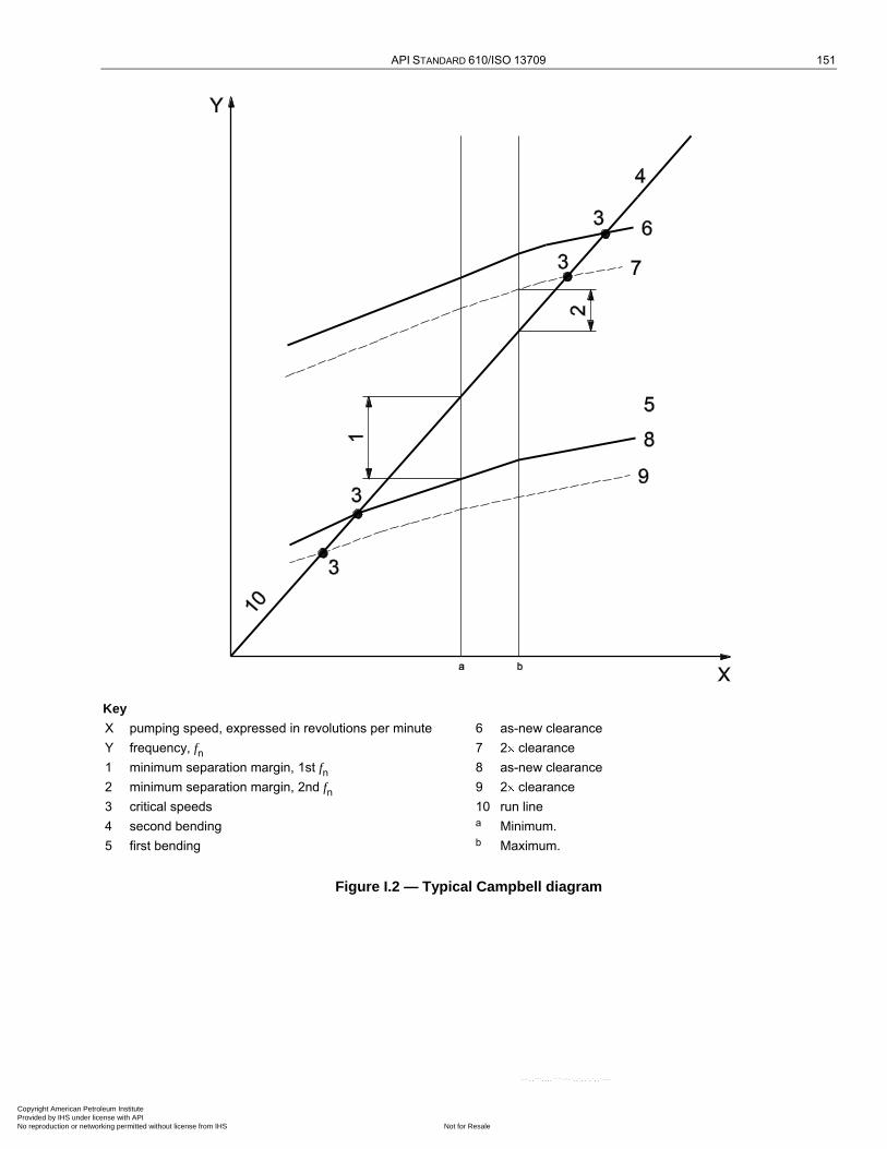
API STANDARD 610/ISO 13709 151
Key
X pumping speed, expressed in revolutions per minute 6 as-new clearance
Y frequency, fn 7 2 clearance
1 minimum separation margin, 1st fn 8 as-new clearance
2 minimum separation margin, 2nd fn 9 2 clearance
3 critical speeds 10 run line
4 second bending a Minimum.
5 first bending b Maximum.
Figure I.2 — Typical Campbell diagram
Copyright American Petroleum Institute Provided by IHS under license with API
Not for ResaleNo reproduction or networking permitted without license from IHS
--`,,```,,,,````-`-`,,`,,`,`,,`---
152 CENTRIFUGAL PUMPS FOR PETROLEUM, PETROCHEMICAL AND NATURAL GAS INDUSTRIES
I.2 Shop verification of rotor dynamic characteristics
I.2.1 If specified, the dynamic characteristics of the rotor shall be verified during the shop test. The rotor's actual response to unbalance shall be the basis for confirming the validity of the damped lateral analysis. This response is measured during either variable-speed operation from rated speed down to 75 % of the first critical speed or during coast-down. If the damped response to unbalance was not determined in the original rotor analysis (see I.1.4), this response shall be determined for a pump with new clearances handling water before proceeding with shop verification. The test unbalances shall be vectorially added in phase with the residual unbalance, at locations determined by the manufacturer (usually at the coupling and/or thrust collar).
NOTE The principal objective of shop verification by response to unbalance is to verify the existence of a critical speed (vibration peak) within the tolerance of the calculated value, or, if the analysis predicted a highly damped critical speed, the absence of a vibration peak within tolerance of the calculated value. Shop verification by this method is feasible only for pumps that have sleeve bearings and that are furnished with proximity probe pairs at each journal bearing.
I.2.2 The magnitude and location of the test unbalance(s) shall be determined from a calibration of the rotor's sensitivity to unbalance. The calibration shall be performed by obtaining the vibration orbits at each bearing,
filtered to rotor speed (1 ), during two trial runs as follows:
a) with the rotor as-built;
b) with trial unbalance weights added 90° from the maximum displacement in run a).
The magnitude of the test unbalances should be such that the calculated maximum shaft displacement caused by the resultant total unbalance (residual plus test) is 150 % to 200 % of the allowable displacement from Table 8 or Table 9 at the bearing probes, but shall not exceed eight times the maximum allowable rotor unbalance.
I.2.3 During the test, the rotor's speed, vibration displacement and corresponding phase angle, filtered to rotor
speed (1 ), shall be measured and recorded.
I.2.4 The rotor's characteristics shall be considered verified if the following requirements are met:
a) observed critical speed(s) (distinct vibration peak and appropriate phase shift) within 10 % of the calculated value(s);
b) measured vibration amplitudes within 35 % of the calculated values.
Highly damped critical speeds might not be observable, therefore the absence of rotor response in the region of a calculated highly damped critical speed is verification of the analysis.
I.2.5 If the acceptance criteria given in I.2.4 are not met, the stiffness or damping coefficients, or both, used in the natural frequency calculation shall be adjusted to produce agreement between the calculated and measured
results. The coefficients of one type of element, annular clearances with L/D 0,15, annular clearances
L/D 0,15, impeller interaction, and bearings shall be adjusted with the same correction factor. Once agreement is reached, the same correction factors shall be applied to the calculation of the rotor's natural frequencies and damping for the pumped liquid, and the rotor's separation margins versus damping factors rechecked for acceptability.
Of the coefficients used in rotor lateral analysis, those for damping in annular clearances have the highest uncertainty and are, therefore, usually the first that are adjusted. The stiffness coefficients of annular clearances typically have a low uncertainty and, therefore, should be adjusted only on the basis of supporting data. Adjustments of bearing coefficients require specific justification because the typical values are based on reliable empirical data.
I.2.6 Alternative methods of verifying the rotor's dynamic characteristics, for example variable-frequency excitation with the pump at running speed to determine the rotor's natural frequencies, are available. The use of alternative methods and the interpretation of the results shall be agreed between the purchaser and manufacturer.
Copyright American Petroleum Institute Provided by IHS under license with API
Not for ResaleNo reproduction or networking permitted without license from IHS
--`,,```,,,,````-`-`,,`,,`,`,,`---
API STANDARD 610/ISO 13709 153
I.3 Documentation
The report on a lateral analysis shall include the following:
a) results of initial assessment (see 9.2.4.1.1);
b) fundamental rotor data used for the analysis, which may be the fundamental model;
c) Campbell diagram (see Figure I.2);
d) plot of damping ratio versus separation margin;
e) mode shape at the critical speed(s) for which the damped response to unbalance is determined (see I.1.4);
f) Bode plot(s) from shop verification by unbalance (see I.2.3);
g) summary of analysis corrections to reach agreement with shop verification (see I.2.5).
Items e) through g) shall be furnished only if the activity documented is required by the analysis or specified by the purchaser.
Copyright American Petroleum Institute Provided by IHS under license with API
Not for ResaleNo reproduction or networking permitted without license from IHS
--`,,```,,,,````-`-`,,`,,`,`,,`---
154
Annex J (normative)
Determination of residual unbalance
J.1 General
This annex describes the procedure used to determine residual unbalance in machine rotors. Although some balancing machines may be set up to read out the exact amount of unbalance, the calibration can be in error. The only sure method of determining residual unbalance is to test the rotor with a known amount of unbalance.
J.2 Terms and definitions
J.2.1 residual unbalance amount of unbalance remaining in a rotor after balancing
NOTE Unless otherwise specified, residual unbalance is expressed in gram-millimetres (g mm) [ounce-inches (oz in)].
J.3 Maximum allowable residual unbalance
J.3.1 The maximum allowable residual unbalance per plane shall be determined from Table 19.
J.3.2 If the actual static load on each journal is not known, assume that the total rotor mass is equally supported by the bearings. For example, a two-bearing rotor with a mass of 2 700 kg (6 000 lb) can be assumed to impose a mass of 1 350 kg (3 000 lb) on each journal.
J.4 Residual unbalance check
J.4.1 General
J.4.1.1 When the balancing machine readings indicate that the rotor has been balanced to within the specified tolerance, a residual unbalance check shall be performed before the rotor is removed from the balancing machine.
J.4.1.2 To check the residual unbalance, a known trial mass is attached to the rotor sequentially in 6 (or 12, if specified by the purchaser) equally spaced radial positions, each at the same radial distance. The check is run in each correction plane, and the readings in each plane are plotted on a graph using the procedure specified in J.4.2.
J.4.2 Procedure
J.4.2.1 Select a trial mass and radius that provides between one and two times the maximum allowable residual unbalance [that is, if Umax is 1 440 g mm (2 oz in), the trial mass is expected to cause 1 440 g mm to 2 880 g mm (2 oz in to 4 oz in) of unbalance].
J.4.2.2 Starting at the last known heavy spot in each correction plane, mark off the specified number of radial positions (6 or 12) in equal (60° or 30°) increments around the rotor. Add the trial mass to the last known heavy spot in one plane. If the rotor has been balanced very precisely and the final heavy spot cannot be determined, add the trial mass to any one of the marked radial positions.
J.4.2.3 To verify that an appropriate trial mass has been selected, operate the balancing machine and record the reading on the meter. If the reading is at the upper limit of the meter range, a smaller trial mass shall be used.
Copyright American Petroleum Institute Provided by IHS under license with API
Not for ResaleNo reproduction or networking permitted without license from IHS
--`,,```,,,,````-`-`,,`,,`,`,,`---
API STANDARD 610/ISO 13709 155
If there is little or no meter reading, a larger trial mass shall be used. Little or no meter reading generally indicates that the rotor was either not balanced correctly, or the balancing machine is not sensitive enough, or the balancing machine is faulty (e.g. a faulty transducer). Whatever the error, it shall be corrected before proceeding with the residual check.
J.4.2.4 Locate the mass at each of the equally spaced positions in turn, and record the amount of unbalance indicated on the meter for each position. Repeat the initial position as a check. All verification shall be performed using only one sensitivity range on the balance machine.
J.4.2.5 Plot the readings on the residual unbalance work sheet and calculate the amount of residual unbalance (see Figures J.1 and J.2). The maximum meter reading occurs when the trial mass is added at the rotor's heavy spot; the minimum reading occurs when the trial mass is located opposite the heavy spot. Thus, the plotted readings are expected to form an approximate circle (see Figures J.3 and J.4). An average of the maximum and minimum meter readings represents the effect of the trial mass. The distance of the circle's centre from the origin of the polar plot represents the residual unbalance in that plane.
J.4.2.6 Repeat the steps described in J.4.2.1 through J.4.2.5 for each balance plane. If the specified maximum allowable residual unbalance is exceeded in any balance plane, the rotor shall be balanced more precisely and checked again. If a correction is made to any balance plane, the residual unbalance check shall be repeated in all planes.
J.4.2.7 For progressively balanced rotors, a residual unbalance check shall be performed after the addition and balancing of the first rotor component, and at the completion of balancing of the entire rotor, as a minimum.
NOTE This ensures that time is not wasted and rotor components are not subjected to unnecessary material removal in attempting to balance a multiple-component rotor with a faulty balancing machine.
Copyright American Petroleum Institute Provided by IHS under license with API
Not for ResaleNo reproduction or networking permitted without license from IHS
--`,,```,,,,````-`-`,,`,,`,`,,`---

156 CENTRIFUGAL PUMPS FOR PETROLEUM, PETROCHEMICAL AND NATURAL GAS INDUSTRIES
Equipment (rotor) No.: ______________
Purchase order No.: ______________
Correction plane (inlet, drive end, etc. — use sketch): ______________
Balancing speed: ______________ r/min
n = maximum allowable rotor speed: ______________ r/min
m (or W) = mass of journal (closest to this correction plane): ______________ kg (lb)
Umax = maximum allowable residual unbalance = 6 350m/n (4W/n)
6 350 ______ kg/______ r/min; (4 ______lb/______r/min) ______________ g mm (oz in)
Trial unbalance (2 Umax) ______________ g mm (oz in)
R = radius of mass placement: ______________ mm (in)
Trial unbalance mass = Trial unbalance/R
_____ g mm/_____ mm (_____ oz in/______in) ______________ g (oz)
NOTE Conversion information: 1 oz = 28,350 g
Test data Rotor sketch
Position Trial mass
angular location Balancing machine amplitude readout
1
2
3
4
5
6
7
Test data — Graphic analysis
Step 1: Plot data on the polar chart (Figure J.2). Scale the chart so the largest and smallest amplitudes will fit conveniently.
Step 2: With a compass, draw the best-fit circle through the six points and mark the centre of this circle.
Step 3: Measure the diameter of the circle in units of scale chosen in Step 1 and record. ______________ units
Step 4: Record the trial unbalance from above. ______________ g mm (oz in)
Step 5: Double the trial unbalance in Step 4 (may use
twice the actual residual unbalance). ______________ g mm (oz in)
Step 6: Divide the answer in Step 5 by the answer in Step 3. ______________ scale factor
You now have a correlation between the units on the polar chart and the actual balance.
Figure J.1 — Residual unbalance work sheet
Copyright American Petroleum Institute Provided by IHS under license with API
Not for ResaleNo reproduction or networking permitted without license from IHS
--`,,```,,,,````-`-`,,`,,`,`,,`---
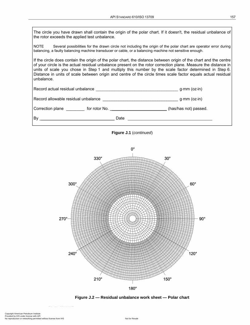
API STANDARD 610/ISO 13709 157
The circle you have drawn shall contain the origin of the polar chart. If it doesn't, the residual unbalance of the rotor exceeds the applied test unbalance.
NOTE Several possibilities for the drawn circle not including the origin of the polar chart are operator error during balancing, a faulty balancing machine transducer or cable, or a balancing machine not sensitive enough.
If the circle does contain the origin of the polar chart, the distance between origin of the chart and the centre of your circle is the actual residual unbalance present on the rotor correction plane. Measure the distance in units of scale you chose in Step 1 and multiply this number by the scale factor determined in Step 6. Distance in units of scale between origin and centre of the circle times scale factor equals actual residual unbalance.
Record actual residual unbalance ____________________________________ g mm (oz in)
Record allowable residual unbalance _________________________________ g mm (oz in)
Correction plane ________ for rotor No. ________________________ (has/has not) passed.
By ________________________________ Date _____________________________________
Figure J.1 (continued)
Figure J.2 — Residual unbalance work sheet — Polar chart
Copyright American Petroleum Institute Provided by IHS under license with API
Not for ResaleNo reproduction or networking permitted without license from IHS
--`,,```,,,,````-`-`,,`,,`,`,,`---
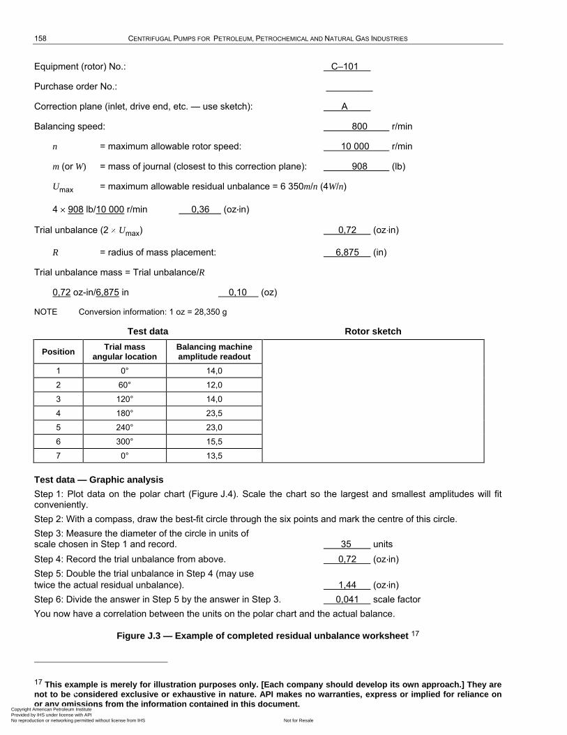
158 CENTRIFUGAL PUMPS FOR PETROLEUM, PETROCHEMICAL AND NATURAL GAS INDUSTRIES
Equipment (rotor) No.: C–101
Purchase order No.: _________
Correction plane (inlet, drive end, etc. — use sketch): A
Balancing speed: 800 r/min
n = maximum allowable rotor speed: 10 000 r/min
m (or W) = mass of journal (closest to this correction plane): 908 (lb)
Umax = maximum allowable residual unbalance = 6 350m/n (4W/n)
4 908 lb/10 000 r/min 0,36 (oz in)
Trial unbalance (2 Umax) 0,72 (oz in)
R = radius of mass placement: 6,875 (in)
Trial unbalance mass = Trial unbalance/R
0,72 oz-in/6,875 in 0,10 (oz)
NOTE Conversion information: 1 oz = 28,350 g
Test data Rotor sketch
Position Trial mass
angular location
Balancing machine
amplitude readout
1 0° 14,0
2 60° 12,0
3 120° 14,0
4 180° 23,5
5 240° 23,0
6 300° 15,5
7 0° 13,5
Test data — Graphic analysis
Step 1: Plot data on the polar chart (Figure J.4). Scale the chart so the largest and smallest amplitudes will fit conveniently.
Step 2: With a compass, draw the best-fit circle through the six points and mark the centre of this circle.
Step 3: Measure the diameter of the circle in units of scale chosen in Step 1 and record. 35 units
Step 4: Record the trial unbalance from above. 0,72 (oz in)
Step 5: Double the trial unbalance in Step 4 (may use
twice the actual residual unbalance). 1,44 (oz in)
Step 6: Divide the answer in Step 5 by the answer in Step 3. 0,041 scale factor
You now have a correlation between the units on the polar chart and the actual balance.
Figure J.3 — Example of completed residual unbalance worksheet 17
17 This example is merely for illustration purposes only. [Each company should develop its own approach.] They are not to be considered exclusive or exhaustive in nature. API makes no warranties, express or implied for reliance on or any omissions from the information contained in this document.
Copyright American Petroleum Institute Provided by IHS under license with API
Not for ResaleNo reproduction or networking permitted without license from IHS
--`,,```,,,,````-`-`,,`,,`,`,,`---
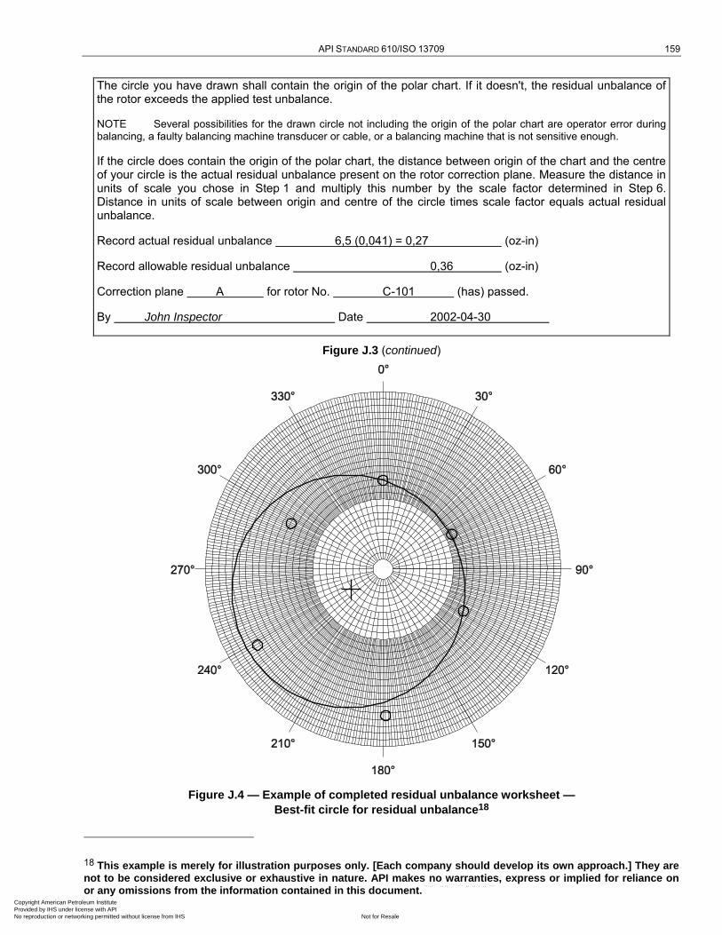
API STANDARD 610/ISO 13709 159
The circle you have drawn shall contain the origin of the polar chart. If it doesn't, the residual unbalance of the rotor exceeds the applied test unbalance.
NOTE Several possibilities for the drawn circle not including the origin of the polar chart are operator error during balancing, a faulty balancing machine transducer or cable, or a balancing machine that is not sensitive enough.
If the circle does contain the origin of the polar chart, the distance between origin of the chart and the centre of your circle is the actual residual unbalance present on the rotor correction plane. Measure the distance in units of scale you chose in Step 1 and multiply this number by the scale factor determined in Step 6. Distance in units of scale between origin and centre of the circle times scale factor equals actual residual unbalance.
Record actual residual unbalance 6,5 (0,041) = 0,27 (oz-in)
Record allowable residual unbalance 0,36 (oz-in)
Correction plane A for rotor No. C-101 (has) passed.
By John Inspector Date 2002-04-30
Figure J.3 (continued)
Figure J.4 — Example of completed residual unbalance worksheet —
Best-fit circle for residual unbalance18
18 This example is merely for illustration purposes only. [Each company should develop its own approach.] They are
not to be considered exclusive or exhaustive in nature. API makes no warranties, express or implied for reliance on or any omissions from the information contained in this document.
Copyright American Petroleum Institute Provided by IHS under license with API
Not for ResaleNo reproduction or networking permitted without license from IHS
--`,,```,,,,````-`-`,,`,,`,`,,`---
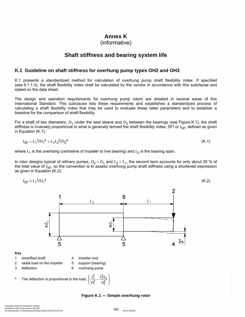
160
Annex K (informative)
Shaft stiffness and bearing system life
K.1 Guideline on shaft stiffness for overhung pump types OH2 and OH3
K.1 presents a standardized method for calculation of overhung pump shaft flexibility index. If specified (see 9.1.1.3), the shaft flexibility index shall be calculated by the vendor in accordance with this subclause and stated on the data sheet.
The design and operation requirements for overhung pump rotors are detailed in several areas of this International Standard. This subclause lists these requirements and establishes a standardized process of calculating a shaft flexibility index that may be used to evaluate these latter parameters and to establish a baseline for the comparison of shaft flexibility.
For a shaft of two diameters, D1 under the seal sleeve and D2 between the bearings (see Figure K.1), the shaft stiffness is inversely proportional to what is generally termed the shaft flexibility index, SFI or ISF, defined as given in Equation (K.1):
ISF L13/D1
4 L1L22/D2
4 (K.1)
where L1 is the overhang (centreline of impeller to line bearing) and L2 is the bearing span.
In rotor designs typical of refinery pumps, D2 D1 and L2 L1, the second term accounts for only about 20 % of the total value of ISF, so the convention is to assess overhung pump shaft stiffness using a shortened expression as given in Equation (K.2):
ISF L13/D1
4 (K.2)
Key
1 simplified shaft 4 impeller end
2 radial load on the impeller 5 support (bearing)
3 deflection 6 overhang pump
a The deflection is proportional to the load, 3 21 1 24 41 2
L L L
D D.
Figure K.1 — Simple overhung rotor
Copyright American Petroleum Institute Provided by IHS under license with API
Not for ResaleNo reproduction or networking permitted without license from IHS
--`,,```,,,,````-`-`,,`,,`,`,,`---
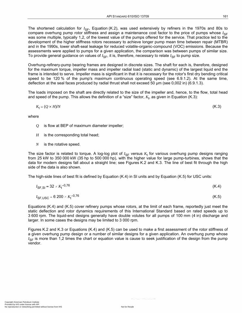
API STANDARD 610/ISO 13709 161
The shortened calculation for ISF, Equation (K.2), was used extensively by refiners in the 1970s and 80s to compare overhung pump rotor stiffness and assign a maintenance cost factor to the price of pumps whose ISF was some multiple, typically 1,2, of the lowest value of the pumps offered for the service. That practice led to the development of the higher stiffness rotors necessary to achieve longer pump mean time between repair (MTBR) and in the 1990s, lower shaft-seal leakage for reduced volatile-organic-compound (VOC) emissions. Because the assessments were applied to pumps for a given application, the comparison was between pumps of similar size. To provide general guidance on values of ISF, it is, therefore, necessary to relate ISF to pump size.
Overhung-refinery-pump bearing frames are designed in discrete sizes. The shaft for each is, therefore, designed for the maximum torque, impeller mass and impeller radial load (static and dynamic) of the largest liquid end the frame is intended to serve. Impeller mass is significant in that it is necessary for the rotor's first dry bending critical speed to be 120 % of the pump's maximum continuous operating speed (see 6.9.1.2). At the same time, deflection at the seal faces produced by radial thrust shall not exceed 50 µm (see 0,002 in) (6.9.1.3).
The loads imposed on the shaft are directly related to the size of the impeller and, hence, to the flow, total head and speed of the pump. This allows the definition of a ―size‖ factor, Kt, as given in Equation (K.3):
Kt (Q H)/N (K.3)
where
Q is flow at BEP of maximum diameter impeller;
H is the corresponding total head;
N is the rotative speed.
The size factor is related to torque. A log-log plot of ISF versus Kt for various overhung pump designs ranging from 25 kW to 350 000 kW (35 hp to 500 000 hp), with the higher value for large pump-turbines, shows that the data for modern designs fall about a straight line; see Figures K.2 and K.3. The line of best fit through the high side of the data is also shown.
The high-side lines of best fit is defined by Equation (K.4) in SI units and by Equation (K.5) for USC units:
ISF,SI 32 Kt–0,76 (K.4)
ISF,USC 6 200 Kt–0,76 (K.5)
Equations (K.4) and (K.5) cover refinery pumps whose rotors, at the limit of each frame, reportedly just meet the static deflection and rotor dynamics requirements of this International Standard based on rated speeds up to 3 600 rpm. The liquid-end designs generally have double volutes for all pumps of 100 mm (4 in) discharge and larger. In some cases the designs may be limited to 3 000 rpm.
Figures K.2 and K.3 or Equations (K.4) and (K.5) can be used to make a first assessment of the rotor stiffness of a given overhung pump design or a number of similar designs for a given application. An overhung pump whose ISF is more than 1,2 times the chart or equation value is cause to seek justification of the design from the pump vendor.
Copyright American Petroleum Institute Provided by IHS under license with API
Not for ResaleNo reproduction or networking permitted without license from IHS
--`,,```,,,,````-`-`,,`,,`,`,,`---
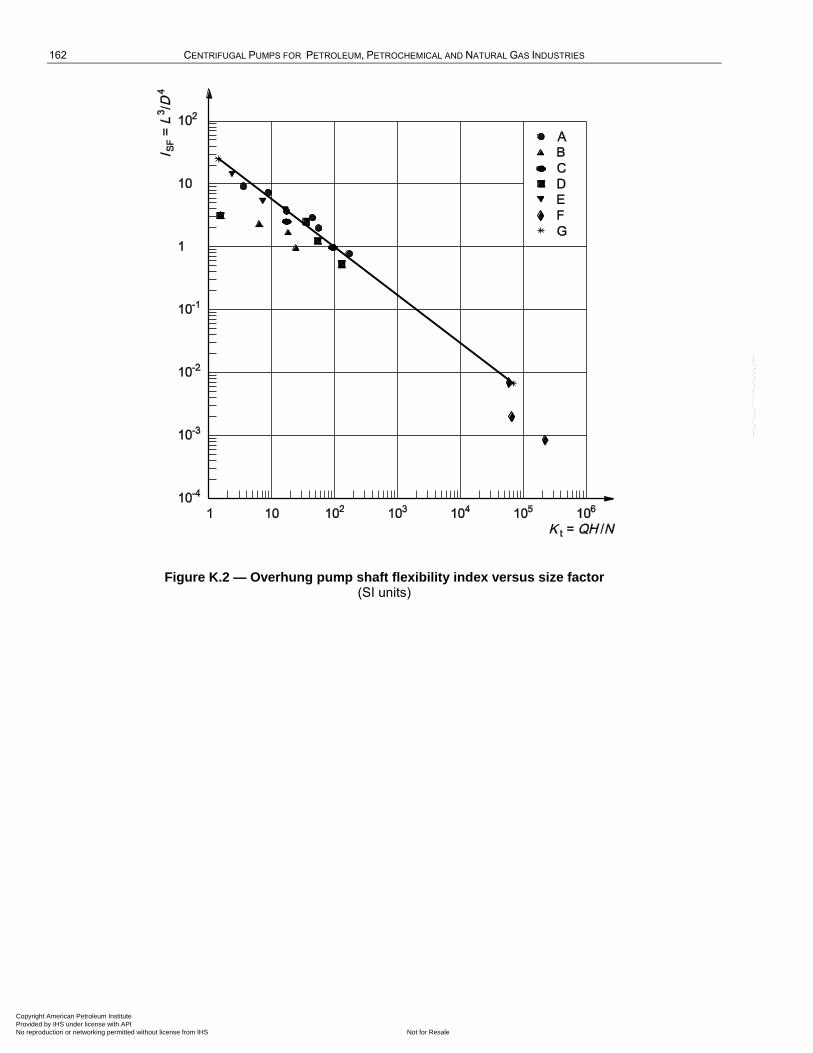
162 CENTRIFUGAL PUMPS FOR PETROLEUM, PETROCHEMICAL AND NATURAL GAS INDUSTRIES
Figure K.2 — Overhung pump shaft flexibility index versus size factor (SI units)
Copyright American Petroleum Institute Provided by IHS under license with API
Not for ResaleNo reproduction or networking permitted without license from IHS
--`,,```,,,,````-`-`,,`,,`,`,,`---
API STANDARD 610/ISO 13709 163
Figure K.3 — Overhung pump shaft flexibility index versus size factor (USC units)
K.2 Bearing system life considerations for OH2, OH3, BB1, BB2 and BB3 pumps
K.2 presents a method of calculating bearing system life. If specified, bearing system life calculations shall be furnished (see 6.10.1.6).
Bearing system life (the calculated life of the combined system of bearings in the pump) shall be equivalent to at least 25 000 h with continuous operation at rated conditions, and at least 16 000 h at maximum radial and axial loads and rated speed. This clause contains a discussion of these requirements.
This International Standard (ANSI/API Std 610/ISO 13709) requires that pumps be designed for 20 years life and 3 years continuous service. Thus, it is necessary that the bearing ―system,‖ not just the individual bearings alone, be designed for a minimum life of 3 years. This is not normally a problem and most user reliability statistics show that bearing life is not a major determinant of overall pump reliability. In cases where bearing life is an issue, the root causes are usually related to lubrication.
Historically, this International Standard has required that ―individual‖ bearings be designed for a minimum L10h life of 25 000 h and 16 000 h at the maximum radial and axial loads and rated speed. Bearing-system life, L10h,sys, is calculated using Equation (K.6), and therefore, is shorter than the shortest life of the individual bearings in the system:
L10h,sys [(1/L10hA)3/2 (1/L10hB)3/2 ... (1/L10hN)3/2] 2/3 (K.6)
where
L10hA is the basic rating life, L10h, in accordance with ISO 281 for bearing A; Copyright American Petroleum Institute Provided by IHS under license with API
Not for ResaleNo reproduction or networking permitted without license from IHS
--`,,```,,,,````-`-`,,`,,`,`,,`---
164 CENTRIFUGAL PUMPS FOR PETROLEUM, PETROCHEMICAL AND NATURAL GAS INDUSTRIES
L10hB is the basic rating life, L10h, in accordance with ISO 281 for bearing B;
L10hN is the basic rating life, L10h, in accordance with ISO 281 for bearing N.
EXAMPLE 1 If a pump has two bearings of equal L10h life (not very likely) and a bearing system life of 25 000 h, the individual bearings would have a L10h life of approximately 37 500 h. Note that because rolling-element bearings are manufactured in standard sizes, it is unlikely that any particular pump would have a calculated L10h life of exactly 37 500 h for both bearings in the system.
EXAMPLE 2 If one bearing has a calculated L10h life of 100 000 h (not unusual), it is necessary for the other bearing in the system to have a calculated L10h life of only about 25 700 h to give a bearing system life of approximately 25 000 h.
OH2, OH3, and to a lesser extent, BB1, BB2 and BB3, pumps are not totally ―engineered pumps‖ in that each component is not necessarily ―designed‖ for a particular purchaser's order requirements. They are generally ―design lines of pumps‖, or pumps that are ―pre-engineered‖ by the manufacturer to meet the requirements of this International Standard within a particular range of operating conditions for specific applications. This is particularly true for BB designs that can have multiple rotor and volute designs within one case pattern using several bearing housing and seal chamber designs. These ―pre-engineered‖ pumps may then be modified, as required, to meet unique applications and purchaser requirements. In the design/product line development process for these pumps, the manufacturer chooses a set of extreme conditions within which he desires to sell ―standard pumps‖. These conditions vary according to the manufacturer's experience with the breadth of services his customers require. These conditions can be chosen to encompass 98 % of all refinery services into which he has sold pumps in, say, a 10 year period.
Once the range of operating conditions has been established, the manufacturer chooses a number of bearing-frame sizes. For most pump manufacturers, this is either three or four sizes for these types of pumps. The manufacturer then matches his available or anticipated sets of hydraulics to the various bearing frames. For each bearing frame, there is a set of hydraulics that imposes the greatest loads on the bearings and frame. For this set of hydraulics, it is necessary that the minimum bearing system life meet the requirements of this International Standard. However, it is completely possible that there are sets of operating conditions or service parameters (such as high suction pressure, low running speed, operating pumps outside the preferred or allowable operating regions) where this pump does not meet all the requirements of this International Standard. For these conditions, the manufacturer has a number of options, including modifying the pump design to meet all the requirements, limiting the pump operating range or negotiation with the purchaser to accept a slightly lower bearing-system life in order to reduce cost or improve overall bearing performance. This can be beneficial if operating conditions are such that bearing loads vary significantly and can result in loads that are too low for optimal bearing performance.
For all other sets of hydraulics, the bearing loads are lower. The equation for bearing life, L10h, as a function of load is given by Equation (K.7), taken from ISO 281:2007, Equation (4):
L10 (Cr /Pr) x (K.7)
where
Cr is the dynamic load rating of the bearing;
Pr is the equivalent dynamic load;
x is 3 for ball bearings and 10/3 for roller bearings.
One can find methods of determining the bearing loads for a pump in the Hydraulic Institute Standards.
Copyright American Petroleum Institute Provided by IHS under license with API
Not for ResaleNo reproduction or networking permitted without license from IHS
--`,,```,,,,````-`-`,,`,,`,`,,`---
API STANDARD 610/ISO 13709 165
Examining Equation (K.6), one can see that for a given bearing, with a given load, a reduction in applied load of 10 % results in an increase in bearing life of approximately 37 %. This means that the calculated bearing-system life for all pumps with a given bearing frame is much greater than the bearing-system life requirement of this International Standard that is applied to the largest set of hydraulics for that bearing frame. Further, for the largest bearing frame, the system life is also greater if the impeller is at less-than-maximum diameter, if the specific gravity is low or if the suction pressure is lower than that used in the limiting case. Further, because bearings with the smallest size having ratings that exceed the calculated loads are chosen, even the largest set of hydraulics can well have a much higher calculated bearing-system life. This gives some insight as to why the historical requirement of 25 000 h L10h life for individual bearings has not been a problem.
It is noted that there are rolling element bearings much larger and with much higher dynamic load ratings that are used in pumps compliant with this International Standard. The application of rolling-element bearings is limited by bearing size and the speed of rotation. It has been found by the pump industry that large bearings running at two-pole speeds (3 000 and 3 600 nominal r/min) tend to run ―hot‖ and can exceed the maximum bearing temperature requirements of this International Standard. As a result of this, all manufacturers limit angular-contact thrust bearings to about 7 315 or 7 316 sizes for two-pole machines. These correspond to shaft sizes of 75 mm and 80 mm (2,95 in and 3,15 in), respectively.
While hot running is detrimental to lubricant and bearing life, the most problematic issue is ball skidding in lightly loaded bearings. If a pump manufacturer applies larger bearings for each frame size, it is necessary that he limit the application of each bearing frame to hydraulics that provide bearing loads sufficient to minimize ball skidding. This means additional bearing-frame sizes can be required to cover all pump sizes in a given product line, thus reducing component production volume, interchangeability and stocking opportunities.
The issue of bearing-system life is an application limitation for pumps of ―standard designs‖.
Copyright American Petroleum Institute Provided by IHS under license with API
Not for ResaleNo reproduction or networking permitted without license from IHS
--`,,```,,,,````-`-`,,`,,`,`,,`---
166
Annex L (informative)
Vendor drawing and data requirements
L.1 General
Figure L.1 shows an example distribution record (schedule). A more detailed description of the entries, keyed to the list number (a, b, c, etc.), is given in L.2.1 for the pump and in L.2.2 for the motor.
Copyright American Petroleum Institute Provided by IHS under license with API
Not for ResaleNo reproduction or networking permitted without license from IHS
--`,,```,,,,````-`-`,,`,,`,`,,`---
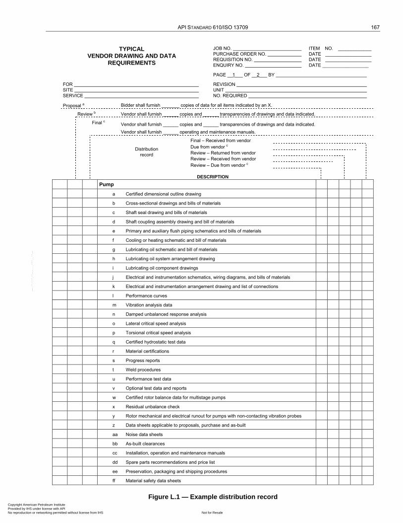
API STANDARD 610/ISO 13709 167
TYPICAL VENDOR DRAWING AND DATA
REQUIREMENTS
JOB NO.
PURCHASE ORDER NO.
REQUISITION NO.
ENQUIRY NO.
ITEM NO. _____________
DATE __________________
DATE __________________
DATE __________________
PAGE __1___ OF __2___ BY
FOR
SITE
SERVICE
REVISION
UNIT
NO. REQUIRED
Proposal a Bidder shall furnish _______ copies of data for all items indicated by an X.
Review b Vendor shall furnish ______ copies and ______ transparencies of drawings and data indicated.
Final c Vendor shall furnish ______ copies and ______ transparencies of drawings and data indicated.
Vendor shall furnish ______ operating and maintenance manuals.
Distribution
record
Final – Received from vendor
Due from vendor c
Review – Returned from vendor
Review – Received from vendor
Review – Due from vendor c
DESCRIPTION
Pump
a Certified dimensional outline drawing
b Cross-sectional drawings and bills of materials
c Shaft seal drawing and bills of materials
d Shaft coupling assembly drawing and bill of materials
e Primary and auxiliary flush piping schematics and bills of materials
f Cooling or heating schematic and bill of materials
g Lubricating oil schematic and bill of materials
h Lubricating oil system arrangement drawing
i Lubricating oil component drawings
j Electrical and instrumentation schematics, wiring diagrams, and bills of materials
k Electrical and instrumentation arrangement drawing and list of connections
l Performance curves
m Vibration analysis data
n Damped unbalanced response analysis
o Lateral critical speed analysis
p Torsional critical speed analysis
q Certified hydrostatic test data
r Material certifications
s Progress reports
t Weld procedures
u Performance test data
v Optional test data and reports
w Certified rotor balance data for multistage pumps
x Residual unbalance check
y Rotor mechanical and electrical runout for pumps with non-contacting vibration probes
z Data sheets applicable to proposals, purchase and as-built
aa Noise data sheets
bb As-built clearances
cc Installation, operation and maintenance manuals
dd Spare parts recommendations and price list
ee Preservation, packaging and shipping procedures
ff Material safety data sheets
Figure L.1 — Example distribution record Copyright American Petroleum Institute Provided by IHS under license with API
Not for ResaleNo reproduction or networking permitted without license from IHS
--`,,```,,,,````-`-`,,`,,`,`,,`---
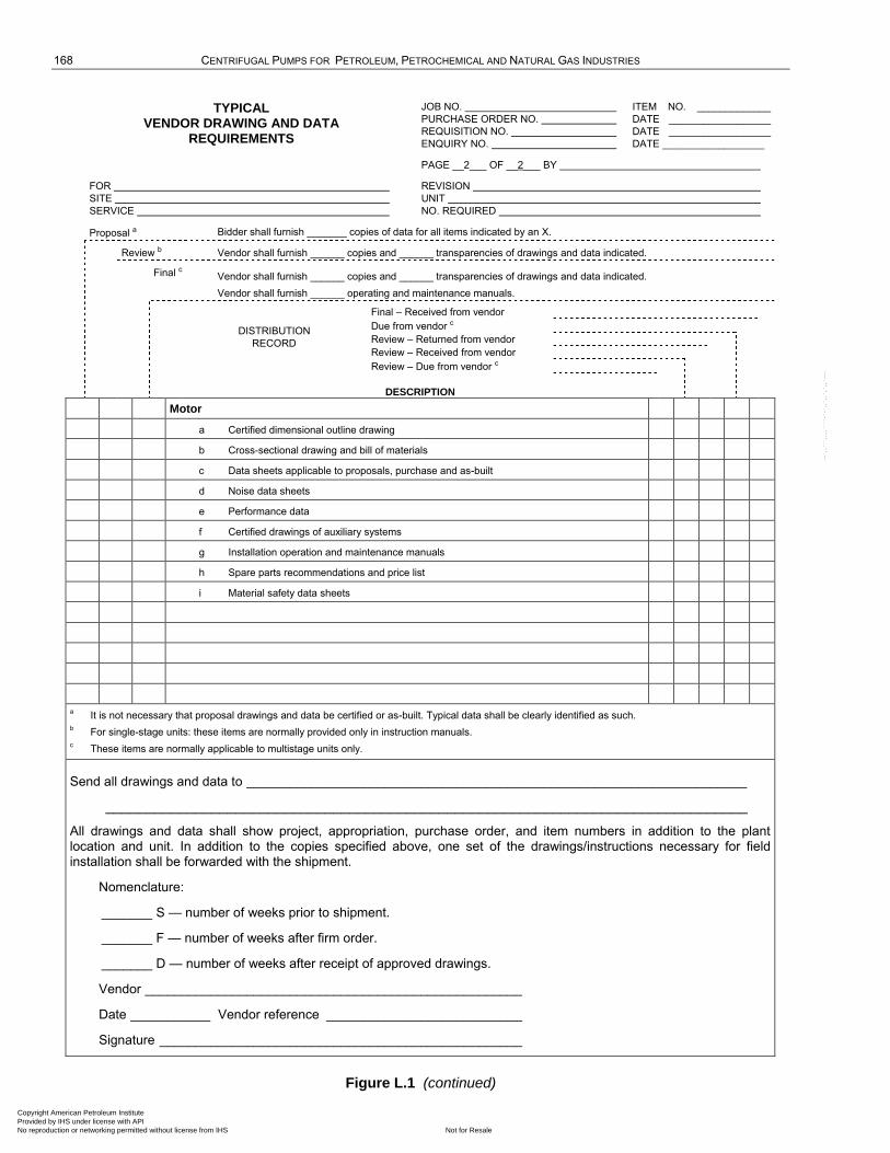
168 CENTRIFUGAL PUMPS FOR PETROLEUM, PETROCHEMICAL AND NATURAL GAS INDUSTRIES
TYPICAL VENDOR DRAWING AND DATA
REQUIREMENTS
JOB NO.
PURCHASE ORDER NO.
REQUISITION NO.
ENQUIRY NO.
ITEM NO. _____________
DATE __________________
DATE __________________
DATE __________________
PAGE __2___ OF __2___ BY
FOR
SITE
SERVICE
REVISION
UNIT
NO. REQUIRED
Proposal a Bidder shall furnish _______ copies of data for all items indicated by an X.
Review b Vendor shall furnish ______ copies and ______ transparencies of drawings and data indicated.
Final c Vendor shall furnish ______ copies and ______ transparencies of drawings and data indicated.
Vendor shall furnish ______ operating and maintenance manuals.
DISTRIBUTION
RECORD
Final – Received from vendor
Due from vendor c
Review – Returned from vendor
Review – Received from vendor
Review – Due from vendor c
DESCRIPTION
Motor
a Certified dimensional outline drawing
b Cross-sectional drawing and bill of materials
c Data sheets applicable to proposals, purchase and as-built
d Noise data sheets
e Performance data
f Certified drawings of auxiliary systems
g Installation operation and maintenance manuals
h Spare parts recommendations and price list
i Material safety data sheets
a It is not necessary that proposal drawings and data be certified or as-built. Typical data shall be clearly identified as such.
b For single-stage units: these items are normally provided only in instruction manuals.
c These items are normally applicable to multistage units only.
Send all drawings and data to _____________________________________________________________________
_______________________________________________________________________________
All drawings and data shall show project, appropriation, purchase order, and item numbers in addition to the plant location and unit. In addition to the copies specified above, one set of the drawings/instructions necessary for field installation shall be forwarded with the shipment.
Nomenclature:
_______ S — number of weeks prior to shipment.
_______ F — number of weeks after firm order.
_______ D — number of weeks after receipt of approved drawings.
Vendor ____________________________________________________
Date ___________ Vendor reference ___________________________
Signature __________________________________________________
Figure L.1 (continued)
Copyright American Petroleum Institute Provided by IHS under license with API
Not for ResaleNo reproduction or networking permitted without license from IHS
--`,,```,,,,````-`-`,,`,,`,`,,`---
API STANDARD 610/ISO 13709 169
L.2 Description
L.2.1 Pump
a) Certified dimensional outline drawing, including the following:
1) size, rating and location of all purchaser connections,
2) approximate overall and handling masses,
3) overall dimensions, and maintenance and dismantling clearances,
4) shaft centreline height,
5) dimensions of baseplates (if furnished) complete with diameters, number and locations of bolt holes, and the thicknesses of sections through which it is necessary that the bolts pass,
6) grouting details,
7) forces and moments for suction and discharge nozzles,
8) centre of gravity and lifting points,
9) shaft end separation and alignment data,
10) direction of rotation,
11) winterization, tropicalization and/or noise attenuation details, if required;
b) cross-sectional drawings and bills of materials;
c) shaft seal drawing and bill of materials;
d) shaft coupling assembly drawing and bill of materials, including allowable misalignment tolerances and the style of the coupling guard;
e) primary and auxiliary sealing schematic and bill of materials, including seal fluid, liquid flows, pressure, pipe and valve sizes, instrumentation, and orifice sizes;
f) cooling or heating schematic and bill of materials, including cooling or heating media, liquid flows, pressure, pipe and valve sizes, instrumentation, and orifice sizes;
g) lubricating oil schematic and bill of materials, including the following:
1) oil flowrates, temperatures and pressures at each use point,
2) control, alarm and trip settings (pressure and recommended temperatures),
3) total head loads,
4) utility requirements, including electricity, water and air,
5) pipe, valve and orifice sizes,
6) instrumentation, safety devices, control schemes, and wiring diagrams;
h) lubricating oil system arrangement drawing, including size, rating, and location of all purchaser connections;
i) lubricating oil component drawings and data, including the following: Copyright American Petroleum Institute Provided by IHS under license with API
Not for ResaleNo reproduction or networking permitted without license from IHS
--`,,```,,,,````-`-`,,`,,`,`,,`---
170 CENTRIFUGAL PUMPS FOR PETROLEUM, PETROCHEMICAL AND NATURAL GAS INDUSTRIES
1) pumps and drivers,
2) coolers, filters and reservoir,
3) instrumentation,
4) spare parts lists and recommendations;
j) electrical and instrumentation schematics, wiring diagrams and bills of materials, including the following:
1) vibration alarm and shutdown limits,
2) bearing temperature alarm and shutdown limits,
3) lubricating oil temperature alarm and shutdown limits,
4) driver;
k) electrical and instrumentation arrangement drawing and list of connections;
l) performance curves;
m) vibration analysis data;
n) damped unbalanced response analysis;
o) lateral critical speed analysis: the required number of lateral critical analysis reports, no later than 3 months after the date of order. The reports shall be as required in I.1.2 and I.1.3.
p) torsional critical speed analysis: the required number of torsional critical analysis reports, no later than 3 months after the date of order. The reports shall be as required in 6.9.2.10.
q) certified hydrostatic test data;
r) material certifications: the vendor's physical and chemical data from mill reports (or certification) of pressure parts, impellers and shafts;
s) progress reports detailing the cause of any delays: the reports shall include engineering, purchasing, manufacturing and testing schedules for all major components. Planned and actual dates, and the percentage completed, shall be indicated for each milestone in the schedule.
t) weld procedures;
u) performance test data: certified shop logs of the performance test, record of shop test data (which the vendor shall maintain for at least 20 years after the date of shipment); the vendor shall submit certified copies of the test data to the purchaser before shipment;
v) optional tests data and reports: optional tests data and reports include NPSH required test, complete unit test, sound level test, auxiliary equipment test, bearing housing resonance test, and any other tests mutually agreed upon by the purchaser and vendor;
w) certified rotor balance data for multistage pumps;
x) residual unbalance check;
y) rotor mechanical and electrical runout for pumps designed to use non-contacting vibration probes;
z) data sheets applicable to proposals, purchase, and as-built;
Copyright American Petroleum Institute Provided by IHS under license with API
Not for ResaleNo reproduction or networking permitted without license from IHS
--`,,```,,,,````-`-`,,`,,`,`,,`---
API STANDARD 610/ISO 13709 171
aa) noise data sheets;
bb) as-built clearances;
cc) instruction manuals describing installation, operation and maintenance procedures; each manual shall include the following sections:
1) Section 1 — Installation:
i) storage,
ii) foundation,
iii) grouting,
iv) setting equipment, rigging procedures, component masses and lifting diagram,
v) alignment,
vi) piping recommendations,
vii) composite outline drawing for pump/driver train, including anchor-bolt locations,
viii) dismantling clearances;
2) Section 2 — Operation:
i) start-up, including tests and checks before start-up,
ii) routine operational procedures,
iii) lubricating oil recommendations;
3) Section 3 — Disassembly and assembly:
i) rotor in pump casing,
ii) journal bearings,
iii) thrust bearings (including clearance and preload on rolling element bearings),
iv) seals,
v) thrust collars, if applicable,
vi) allowable wear of running clearances,
vii) fits and clearances for rebuilding,
viii) routine maintenance procedures and intervals;
4) Section 4 — Performance curves, including differential head, efficiency, water NPSH3, and brake horsepower versus flowrate for all operating conditions specified on the data sheets;
5) Section 5 — Vibration data:
i) vibration analysis data,
ii) lateral critical speed analysis, Copyright American Petroleum Institute Provided by IHS under license with API
Not for ResaleNo reproduction or networking permitted without license from IHS
--`,,```,,,,````-`-`,,`,,`,`,,`---
172 CENTRIFUGAL PUMPS FOR PETROLEUM, PETROCHEMICAL AND NATURAL GAS INDUSTRIES
iii) torsional critical speed analysis;
6) Section 6 — As-built data:
i) as-built data sheets,
ii) as-built clearances,
iii) rotor balance data for multi-stage pumps,
iv) noise data sheets,
v) performance data;
7) Section 7 — Drawing and data requirements:
i) certified dimensional outline drawing and list of connections,
ii) cross-sectional drawing and bill of materials,
iii) shaft seal drawing and bill of materials,
iv) lubricating oil arrangement drawing and list of connections,
v) lubricating oil component drawings and data, and bills of materials,
vi) electrical and instrumentation schematics, wiring diagrams and bills of materials,
vii) electrical and instrumentation arrangement drawing and list of connections,
viii) coupling assembly drawing and bill of materials,
ix) primary and auxiliary seal schematic and bill of materials,
x) primary and auxiliary seal piping, instrumentation, arrangement and list of connections,
xi) cooling and heating schematic and bill of materials,
xii) cooling or heating piping, instrumentation arrangement and list of connections;
dd) spare parts recommendations and price list;
ee) preservation, packaging and shipping procedure;
ff) material safety data sheets.
L.2.2 Motor
a) Certified dimensional outline drawing for motor and all auxiliary equipment, including the following:
1) size, location, and purpose of all purchaser connections, including conduit, instrumentation, and any piping or ducting,
2) ASME rating and facing for any flanged connections,
3) size and location of anchor bolt holes and thicknesses of sections through which bolts must pass,
4) total mass of each item of equipment (motor and auxiliary equipment) plus loading diagrams, heaviest mass, and name of the part,
Copyright American Petroleum Institute Provided by IHS under license with API
Not for ResaleNo reproduction or networking permitted without license from IHS
--`,,```,,,,````-`-`,,`,,`,`,,`---

API STANDARD 610/ISO 13709 173
5) overall dimensions and all horizontal and vertical clearances necessary for dismantling, and the approximate location of lifting lugs,
6) shaft centreline height,
7) shaft end dimensions, plus tolerances for the coupling,
8) direction of rotation;
b) cross-sectional drawing and bill of materials, including the axial rotor float;
c) data sheets applicable to proposals, purchase, and as-built;
d) noise data sheets;
e) performance data including the following:
1) for induction motors 150 kW (200 hp) and smaller:
i) efficiency and power factor at one-half, three-quarter, and full load,
ii) speed-torque curves;
2) for induction motors larger than 150 kW (200 hp) and larger, certified test reports for all test run and performance curves as follows:
i) time-current heating curve,
ii) speed-torque curves at 70 %, 80 %, 90 % and 100 % of rated voltage,
iii) efficiency and power factor curves from 0 to rated service factor,
iv) current versus load curves from 0 to rated service factor,
v) current versus speed curves from 0 to 100 % of rated speed;
f) certified drawings of auxiliary systems, including wiring diagrams, for each auxiliary system supplied; the drawings shall clearly indicate the extent of the system being supplied by the manufacturer and the extent being supplied by others;
g) motor instruction manuals describing installation, operating and maintenance procedures. Each manual shall include the following sections:
1) Section 1 — Installation:
i) storage,
ii) setting motor, rigging procedures, component masses and lifting diagram,
iii) piping and conduit recommendations,
iv) composite outline drawing for motor, including locations of anchor-bolt holes,
v) dismantling clearances;
2) Section 2 — Operation:
i) start-up, including check before start-up,
Copyright American Petroleum Institute Provided by IHS under license with API
Not for ResaleNo reproduction or networking permitted without license from IHS
--`,,```,,,,````-`-`,,`,,`,`,,`---

174 CENTRIFUGAL PUMPS FOR PETROLEUM, PETROCHEMICAL AND NATURAL GAS INDUSTRIES
ii) normal shutdown,
iii) operating limits, including number of successive starts,
iv) lubricating oil recommendations;
3) Section 3 — Disassembly and assembly instructions:
i) rotor in motor,
ii) journal bearings,
iii) seals,
iv) routine maintenance procedures and intervals;
4) Section 4 — Performance data required by L.2.2 e):
5) Section 5 — Data sheets:
i) as-built data sheets,
ii) noise data sheets;
6) Section 6 — Drawing and data requirements:
i) certified dimensional outline drawing for motor and all auxiliary equipment, with list of connections,
ii) cross-sectional drawing and bill of materials;
h) spare parts recommendations and price list;
i) material safety data sheets.
Copyright American Petroleum Institute Provided by IHS under license with API
Not for ResaleNo reproduction or networking permitted without license from IHS
--`,,```,,,,````-`-`,,`,,`,`,,`---
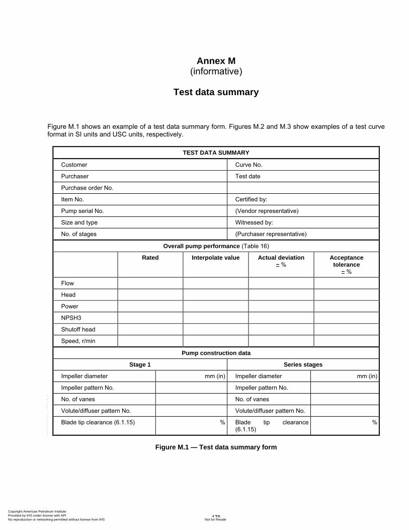
175
Annex M (informative)
Test data summary
Figure M.1 shows an example of a test data summary form. Figures M.2 and M.3 show examples of a test curve format in SI units and USC units, respectively.
TEST DATA SUMMARY
Customer Curve No.
Purchaser Test date
Purchase order No.
Item No. Certified by:
Pump serial No. (Vendor representative)
Size and type Witnessed by:
No. of stages (Purchaser representative)
Overall pump performance (Table 16)
Rated Interpolate value Actual deviation %
Acceptance tolerance
%
Flow
Head
Power
NPSH3
Shutoff head
Speed, r/min
Pump construction data
Stage 1 Series stages
Impeller diameter mm (in) Impeller diameter mm (in)
Impeller pattern No. Impeller pattern No.
No. of vanes No. of vanes
Volute/diffuser pattern No. Volute/diffuser pattern No.
Blade tip clearance (6.1.15) % Blade tip clearance (6.1.15)
%
Figure M.1 — Test data summary form
Copyright American Petroleum Institute Provided by IHS under license with API
Not for ResaleNo reproduction or networking permitted without license from IHS
--`,,```,,,,````-`-`,,`,,`,`,,`---
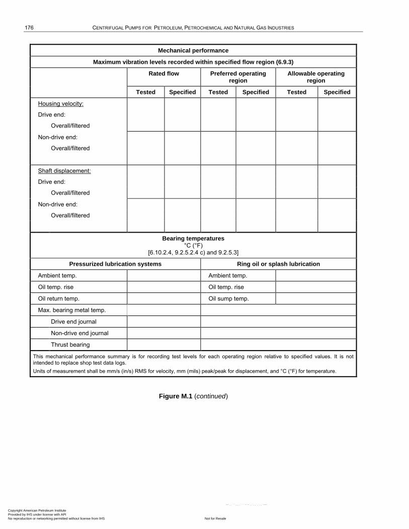
176 CENTRIFUGAL PUMPS FOR PETROLEUM, PETROCHEMICAL AND NATURAL GAS INDUSTRIES
Mechanical performance
Maximum vibration levels recorded within specified flow region (6.9.3)
Rated flow Preferred operating region
Allowable operating region
Tested Specified Tested Specified Tested Specified
Housing velocity:
Drive end:
Overall/filtered
Non-drive end:
Overall/filtered
Shaft displacement:
Drive end:
Overall/filtered
Non-drive end:
Overall/filtered
Bearing temperatures °C (°F)
[6.10.2.4, 9.2.5.2.4 c) and 9.2.5.3]
Pressurized lubrication systems Ring oil or splash lubrication
Ambient temp. Ambient temp.
Oil temp. rise Oil temp. rise
Oil return temp. Oil sump temp.
Max. bearing metal temp.
Drive end journal
Non-drive end journal
Thrust bearing
This mechanical performance summary is for recording test levels for each operating region relative to specified values. It is not
intended to replace shop test data logs.
Units of measurement shall be mm/s (in/s) RMS for velocity, mm (mils) peak/peak for displacement, and °C (°F) for temperature.
Figure M.1 (continued)
Copyright American Petroleum Institute Provided by IHS under license with API
Not for ResaleNo reproduction or networking permitted without license from IHS
--`,,```,,,,````-`-`,,`,,`,`,,`---
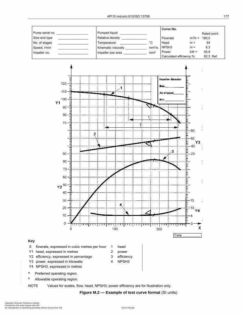
API STANDARD 610/ISO 13709 177
Pump serial no. __________________
Size and type _________________
No. of stages _________________
Speed, r/min _________________
Impeller no. _________________
Pumped liquid _______________
Relative density ______________
Temperature _______________ °C
Kinematic viscosity ____________ mm2/s
Impeller eye area _____________ mm2
Curve No.
Rated point
Flowrate m3/h = 180,0
Head m = 94
NPSH3 m = 6,3
Power kW = 55,9
Calculated efficiency %: 82,3 Ref.
Key
X flowrate, expressed in cubic metres per hour 1 head
Y1 head, expressed in metres 2 power
Y2 efficiency, expressed in percentage 3 efficiency
Y3 power, expressed in kilowatts 4 NPSH3
Y4 NPSH3, expressed in metres
a Preferred operating region.
b Allowable operating region.
NOTE Values for scales, flow, head, NPSH3, power efficiency are for illustration only.
Figure M.2 — Example of test curve format (SI units)
Copyright American Petroleum Institute Provided by IHS under license with API
Not for ResaleNo reproduction or networking permitted without license from IHS
--`,,```,,,,````-`-`,,`,,`,`,,`---
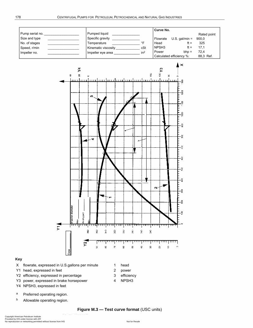
178 CENTRIFUGAL PUMPS FOR PETROLEUM, PETROCHEMICAL AND NATURAL GAS INDUSTRIES
Pump serial no. ___________________
Size and type _________________
No. of stages _________________
Speed, r/min _________________
Impeller no. _________________
Pumped liquid _______________
Specific gravity _______________
Temperature _______________ °F
Kinematic viscosity _____________ cSt
Impeller eye area ______________ in2
Curve No.
Rated point
Flowrate U.S. gal/min = 900,0
Head ft = 325
NPSH3 ft = 17,1
Power bhp = 72,4
Calculated efficiency %: 88,3 Ref.
Key
X flowrate, expressed in U.S.gallons per minute 1 head
Y1 head, expressed in feet 2 power
Y2 efficiency, expressed in percentage 3 efficiency
Y3 power, expressed in brake horsepower 4 NPSH3
Y4 NPSH3, expressed in feet
a Preferred operating region.
b Allowable operating region.
Figure M.3 — Test curve format (USC units)
Copyright American Petroleum Institute Provided by IHS under license with API
Not for ResaleNo reproduction or networking permitted without license from IHS
--`,,```,,,,````-`-`,,`,,`,`,,`---

179
Annex N (informative)
Pump datasheets and electronic data exchange
N.1 Pump data sheets
This annex contains typical datasheets for use by the purchaser and the vendor as shown in Figure N.1 and Figure N.2. The datasheets, in both SI and USC units, are copies of the electronic form of the datasheets (Microsoft Excel Spreadsheets). In the electronic form, selection of the units on the datasheet will automatically change all the units on the datasheet to the units selected. Note however, that this electronic datasheet does not contain in-built calculations, therefore changing the units will not impact any data entered onto the datasheet.
The datasheet is intended to be used in its electronic format and as such, there are numerous cells that contain dropdown selections. As these selections are not presented to the user until the cell is selected, the copies in this document indicate which cells contain a drop-down selection in the shaded areas. Another feature of the electronic datasheet is that when the user selects a data entry cell, if there is a cross reference back to the standard a pop-up box will appear indicating the reference paragraph and some or all of the content of the referenced paragraph.
To assist the reader a document map (See Figure N.3), which is basically the datasheet less all content, has been prepared which lists the content of the drop-down selection at each line as applicable. In addition to the drop-down list, there are some lines with numbers listed on the left-hand side of the area. These numbers are the numbers of the crossed referenced paragraphs, which pop-up as mentioned above.
In all instances the document map lists the information on the same line as the electronic datasheet.
N.2 Electronic data exchange (EDE)
The information contained in pump data sheets may also be transmitted digitally rather than via a conventional data sheet format. This is suitable when pump purchaser and supplier have systems that can process digital information rather than paper-based data sheets. Direct electronic transfer can be achieved with a transfer protocol that is adopted by both purchaser and supplier. It is necessary that this transfer protocol also be commercially neutral for it to be accepted by all parties. Such a method improves the operating efficiencies of both parties if their internal data systems can import/export via this neutral protocol. Examples of these systems include
a) for the purchaser:
1) pump specifications database,
2) bid tab program,
3) system analysis program,
4) as-built asset management program;
b) for the supplier:
1) pump selection system,
2) pump configuration and quotation development system,
3) order management system and bill-of-material management system. Copyright American Petroleum Institute Provided by IHS under license with API
Not for ResaleNo reproduction or networking permitted without license from IHS
--`,,```,,,,````-`-`,,`,,`,`,,`---
180 CENTRIFUGAL PUMPS FOR PETROLEUM, PETROCHEMICAL AND NATURAL GAS INDUSTRIES
Those interested in adopting electronic data exchange (EDE) are encouraged to reference the EDE technology and implementation standard, BSR/HI 50.7, for the digital transfer of centrifugal pump data. This standard provides implementation details and examples towards adopting EDE that is suitable for ANSI/API Std 610/ISO 13709 centrifugal pump data. Additional interpretive information is also available at http://www.pumps.org/ede.
BSR/HI 50.7 was developed and supported by the Hydraulic Institute and the FIATECH automating equipment information exchange (AEX) project, in cooperation with the API. Information on the EDE technology and the AEX XML schemas is available on line at www.fiatech.org/aex.html.
A complete listing of all data fields in the electronic data sheets N.3.1 through N.3.3 and their corresponding XML structures are found in BSR/HI 50.7 www.pumps.org/ede or via FIATECH at www.fiatech.org/aex.html.
Copyright American Petroleum Institute Provided by IHS under license with API
Not for ResaleNo reproduction or networking permitted without license from IHS
--`,,```,,,,````-`-`,,`,,`,`,,`---
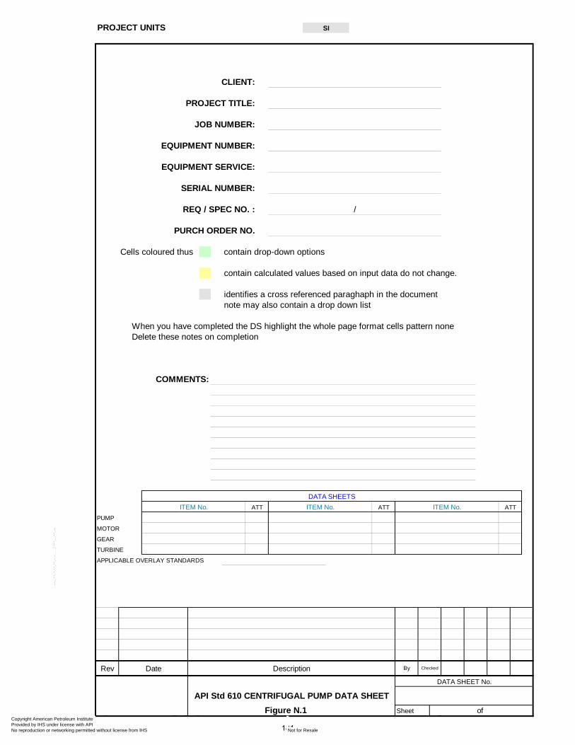
CLIENT:
PROJECT TITLE:
JOB NUMBER:
EQUIPMENT NUMBER:
EQUIPMENT SERVICE:
SERIAL NUMBER:
REQ / SPEC NO. : /
PURCH ORDER NO.
Cells coloured thus contain drop-down options
contain calculated values based on input data do not change.
identifies a cross referenced paraghaph in the documentnote may also contain a drop down list
When you have completed the DS highlight the whole page format cells pattern noneDelete these notes on completion
COMMENTS:
PUMP
MOTOR
GEAR
TURBINE
APPLICABLE OVERLAY STANDARDS
Rev Date Description
DATA SHEET No.
API Std 610 CENTRIFUGAL PUMP DATA SHEETFigure N.1 Sheet of
By Checked
ITEM No. ATT
SIPROJECT UNITS
DATA SHEETSATTITEM No. ATTITEM No.
181
Copyright American Petroleum Institute Provided by IHS under license with API
Not for ResaleNo reproduction or networking permitted without license from IHS
--`,,```,,,,````-`-`,,`,,`,`,,`---
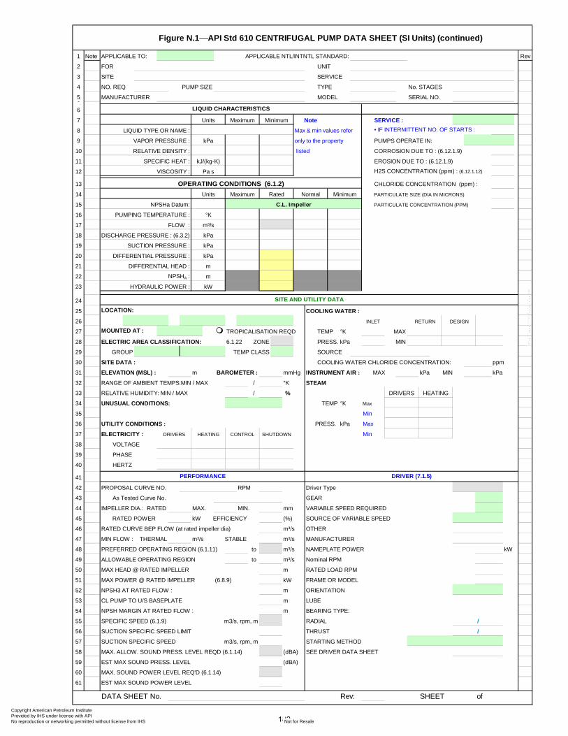
Figure N.1⎯API Std 610 CENTRIFUGAL PUMP DATA SHEET (SI Units) (continued)
1 Note APPLICABLE TO: APPLICABLE NTL/INTNTL STANDARD: Rev
2 FOR UNIT
3 SITE SERVICE
4 NO. REQ PUMP SIZE TYPE No. STAGES
5 MANUFACTURER MODEL SERIAL NO.6
6
7 SERVICE :
8 LIQUID TYPE OR NAME : Max & min values refer • IF INTERMITTENT NO. OF STARTS :
9 VAPOR PRESSURE : only to the property PUMPS OPERATE IN:
10 listed CORROSION DUE TO : (6.12.1.9)
11 SPECIFIC HEAT : EROSION DUE TO : (6.12.1.9)
12 VISCOSITY : H2S CONCENTRATION (ppm) : (6.12.1.12)
13 CHLORIDE CONCENTRATION (ppm) :
14 PARTICULATE SIZE (DIA IN MICRONS)
15 NPSHa Datum: PARTICULATE CONCENTRATION (PPM)
16 PUMPING TEMPERATURE :
17 FLOW :
18 DISCHARGE PRESSURE : (6.3.2)
19 SUCTION PRESSURE :
20
21
22
23
24
25 LOCATION: COOLING WATER :
26
27 MOUNTED AT : TEMP °K MAX
28 ELECTRIC AREA CLASSIFICATION: 6.1.22 ZONE PRESS. kPa MIN
29 GROUP TEMP CLASS SOURCE
30 SITE DATA : COOLING WATER CHLORIDE CONCENTRATION: ppm
31 ELEVATION (MSL) : m BAROMETER : mmHg INSTRUMENT AIR : MAX kPa MIN kPa
32 RANGE OF AMBIENT TEMPS:MIN / MAX / °K STEAM
33 RELATIVE HUMIDITY: MIN / MAX / %
34 UNUSUAL CONDITIONS: TEMP °K Max
35 Min
36 UTILITY CONDITIONS : PRESS. kPa Max
37 ELECTRICITY : Min
38 VOLTAGE
39 PHASE
40 HERTZ
41
42 PROPOSAL CURVE NO. RPM Driver Type
43 As Tested Curve No. GEAR
44 IMPELLER DIA.: RATED MAX. MIN. mm VARIABLE SPEED REQUIRED
45 RATED POWER kW EFFICIENCY (%) SOURCE OF VARIABLE SPEED
46 RATED CURVE BEP FLOW (at rated impeller dia) m³/s OTHER
47 MIN FLOW : THERMAL m³/s STABLE m³/s MANUFACTURER
48 PREFERRED OPERATING REGION (6.1.11) to m³/s NAMEPLATE POWER kW
49 ALLOWABLE OPERATING REGION to m³/s Nominal RPM
50 MAX HEAD @ RATED IMPELLER m RATED LOAD RPM
51 MAX POWER @ RATED IMPELLER (6.8.9) kW FRAME OR MODEL
52 NPSH3 AT RATED FLOW : m ORIENTATION
53 CL PUMP TO U/S BASEPLATE m LUBE
54 NPSH MARGIN AT RATED FLOW : m BEARING TYPE:
55 SPECIFIC SPEED (6.1.9) m3/s, rpm, m RADIAL
56 SUCTION SPECIFIC SPEED LIMIT THRUST
57 SUCTION SPECIFIC SPEED m3/s, rpm, m STARTING METHOD
58 MAX. ALLOW. SOUND PRESS. LEVEL REQD (6.1.14) (dBA) SEE DRIVER DATA SHEET
59 EST MAX SOUND PRESS. LEVEL (dBA)
60 MAX. SOUND POWER LEVEL REQ'D (6.1.14)
61 EST MAX SOUND POWER LEVEL
DATA SHEET No. Rev: SHEET of
m³/s
kPa
/
/
DRIVER (7.1.5)PERFORMANCE
Units NoteMaximum
LIQUID CHARACTERISTICS
RELATIVE DENSITY :
Pa s
OPERATING CONDITIONS (6.1.2)
kJ/(kg-K)
Minimum
DIFFERENTIAL PRESSURE : kPa
DIFFERENTIAL HEAD :
kPa
DESIGN
Units Normal
m
kPa
°K
Minimum
NPSHA :
HYDRAULIC POWER :
m
kW
SITE AND UTILITY DATA
HEATINGDRIVERS CONTROL SHUTDOWN
RETURN
TROPICALISATION REQD
INLET
HEATINGDRIVERS
C.L. Impeller
Maximum Rated
182
Copyright American Petroleum Institute Provided by IHS under license with API
Not for ResaleNo reproduction or networking permitted without license from IHS
--`,,```,,,,````-`-`,,`,,`,`,,`---

Figure N.1⎯API Std 610 CENTRIFUGAL PUMP DATA SHEET (SI Units) (continued)
1 Note Rev
2 API PUMP TYPE: [Based on API 610 definitions] CASING MOUNTING:
3 CASING TYPE: (6.3.10)
4 NOZZLE CONNECTIONS: (6.5.5) OH3 BACKPULLOUT LIFTING DEVICE REQD. (9.1.2.6)
5 CASE PRESSURE RATING:
6 SUCTION MAWP : (6.3.6) kPa @ °K
7 DISCHARGE HYDROTEST : kPa @ °K
8 PRESSURE CASING AUX. CONNECTIONS: (6.4.3.2)
9 HYDROTEST OH PUMP AS ASSEMBLY
10 BALANCE/LEAK OFF SUCT'N PRESS. REGIONS DESIGNED FOR MAWP
11 DRAIN ROTATION: (VIEWED FROM COUPLING END)
12 VENT • IMPELLERS INDIVIDUALLY SECURED :
13 PRESSURE GAGE • BOLT OH 3/4/5 PUMP TO PAD / FOUNDATION :
14 TEMP GAGE • PROVIDE SOLEPLATE FOR OH 3/4/5 PUMPS
15 WARM-UP LINE ROTOR:
16 SHAFT FLEXIBILITY INDEX (SFI) (9.1.1.3)
17 Drain Valve Supplied By First Critical Speed Wet (Multi stage pumps only)
18 DRAINS MANIFOLDED COMPONENT BALANCE TO ISO 1940 G1.0
19 VENT Valve Supplied By SHRINK FIT -LIMITED MOVEMENT IMPELLERS (9.2.2.3)
20 VENTS MANIFOLDED
21 THREADED CONS FOR PIPELINE SERVICE & < 50°C (6.4.3.2) COUPLING:(7.2.3) (7.2.13.f)
22 SPECIAL FITTINGS FOR TRANSITIONING (6.4.3.3) MANUFACTURER
23 CYLINDRICAL THREADS REQUIRED (6.4.3.8) MODEL
24 GUSSET SUPPORT REQUIRED RATING (POWER/100 RPM)
25 MACHINED AND STUDDED CONNECTIONS (6.4.3.12) SPACER LENGTH mm
26 VS 6 DRAIN SERVICE FACTOR
27 DRAIN TO SKID EDGE RIGID
28 COUPLING WITH HYDRAULIC FIT (7.2.10)
29 COUPLING BALANCED TO ISO 1940-1 G6.3 (7.2.3)
30 APPENDIX H CLASS COUPLING WITH PROPRIETARY CLAMPING DEVICE (7.2.11)
31 MIN DESIGN METAL TEMP (6.12.4.1) °K
32 REDUCED-HARDNESS MATERIALS REQ'D (6.12.1.12.1) COUPLING IN COMPLIANCE WITH (7.2.4)
33 Applicable Hardness Standard (6.12.1.12.3) COUPLING GUARD STANDARD PER (7.2.13.a)
34 BARREL : Window on Coupling Guard
35 CASE :
36 DIFFUSERS
37 IMPELLER : API BASEPLATE NUMBER :
38 IMPELLER WEAR RING : BASEPLATE CONSTRUCTION (7.3.14)
39 CASE WEAR RING : BASEPLATE DRAINAGE (7.3.1)
40 SHAFT: MOUNTING :
41 Bowl (if VS-type) NON-GROUT CONSTRUCTION : (7.3.13)
42 Inspection Class VERTICAL LEVELING SCREWS :
43 LONGITUDINAL DRIVER POSITIONING SCREWS :
44 BEARING (TYPE / NUMBER): (6.11.4) SUPPLIED WITH : GROUT AND VENT HOLES
45 RADIAL / DRAIN CONNECTION
46 THRUST / MOUNTING PADS SIZED FOR BASEPLATE LEVELING (7.3.5)
47 REVIEW AND APPROVE THRUST BEARING SIZE : (9.2.5.2.4) MOUNTING PADS TO BE MACHINED (7.3.6)
48 PROVIDE SPACER PLATE UNDER ALL EQUIPMENT FEET
49 LUBRICATION : (6.10.2.2) (6.11.3) (9.6.1) OTHER
50 PRESSURE LUBE SYSTEM TO ISO 10438- (9.2.6.5)
50 ISO 10438 DATA SHEETS ATTACHED
51 Pressurized Lube Oil System mtd on pump baseplate REMARKS :
52 Location of Pressurized Lube Oil System mounted on baseplate :
53
54 INTERCONNECTING PIPING PROVIDED BY
55
56 OIL VISC. ISO GRADE VG
57 CONSTANT LEVEL OILER :
DATA SHEET No. Rev: SHEET of
CONSTRUCTION
BEARINGS AND LUBRICATION (6.10.1.1)
Facing Rating
BASEPLATE
No.
MATERIAL (6.12.1.1)
Facing
TypeSize
Size Position
Posn.
Rating
183
Copyright American Petroleum Institute Provided by IHS under license with API
Not for ResaleNo reproduction or networking permitted without license from IHS
--`,,```,,,,````-`-`,,`,,`,`,,`---
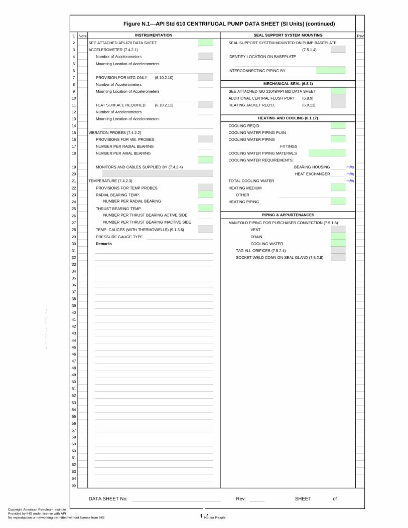
Figure N.1⎯API Std 610 CENTRIFUGAL PUMP DATA SHEET (SI Units) (continued)
1 Note Rev
2 SEE ATTACHED API-670 DATA SHEET SEAL SUPPORT SYSTEM MOUNTED ON PUMP BASEPLATE
3 ACCELEROMETER (7.4.2.1) (7.5.1.4)
4 Number of Accelerometers IDENTIFY LOCATION ON BASEPLATE
5 Mounting Location of Accelerometers
6 INTERCONNECTING PIPING BY
7 PROVISION FOR MTG ONLY (6.10.2.10)
8 Number of Accelerometers
9 Mounting Location of Accelerometers SEE ATTACHED ISO 21049/API 682 DATA SHEET
10 ADDITIONAL CENTRAL FLUSH PORT (6.8.9)
11 FLAT SURFACE REQUIRED (6.10.2.11) HEATING JACKET REQ'D. (6.8.11)
12 Number of Accelerometers
13 Mounting Location of Accelerometers
14 COOLING REQ'D
15 VIBRATION PROBES (7.4.2.2) COOLING WATER PIPING PLAN
16 PROVISIONS FOR VIB. PROBES COOLING WATER PIPING
17 NUMBER PER RADIAL BEARING FITTINGS
18 NUMBER PER AXIAL BEARING COOLING WATER PIPING MATERIALS
COOLING WATER REQUIREMENTS:
19 MONITORS AND CABLES SUPPLIED BY (7.4.2.4) BEARING HOUSING m³/s
20 HEAT EXCHANGER m³/s
21 TEMPERATURE (7.4.2.3) TOTAL COOLING WATER m³/s
22 PROVISIONS FOR TEMP PROBES HEATING MEDIUM
23 RADIAL BEARING TEMP. OTHER
24 NUMBER PER RADIAL BEARING HEATING PIPING
25 THRUST BEARING TEMP.
26 NUMBER PER THRUST BEARING ACTIVE SIDE
27 NUMBER PER THRUST BEARING INACTIVE SIDE MANIFOLD PIPING FOR PURCHASER CONNECTION (7.5.1.6)
28 TEMP. GAUGES (WITH THERMOWELLS) (9.1.3.6) VENT
29 PRESSURE GAUGE TYPE DRAIN
30 Remarks COOLING WATER
31 TAG ALL ORIFICES (7.5.2.4)
32 SOCKET WELD CONN ON SEAL GLAND (7.5.2.8)
33
34
35
36
37
38
39
40
41
42
43
44
45
46
47
48
49
50
51
52
53
54
55
56
57
58
59
60
61
62
63
64
65
DATA SHEET No. Rev: SHEET of
INSTRUMENTATION SEAL SUPPORT SYSTEM MOUNTING
PIPING & APPURTENANCES
MECHANICAL SEAL (6.8.1)
HEATING AND COOLING (6.1.17)
184
Copyright American Petroleum Institute Provided by IHS under license with API
Not for ResaleNo reproduction or networking permitted without license from IHS
--`,,```,,,,````-`-`,,`,,`,`,,`---
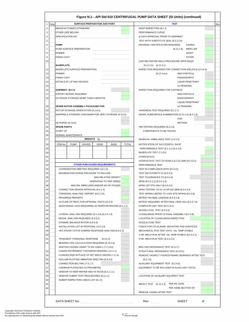
Figure N.1⎯API Std 610 CENTRIFUGAL PUMP DATA SHEET (SI Units) (continued)
1 Note Rev
2 MANUFACTURER'S STANDARD SHOP INSPECTION (8.1.1)
3 OTHER (SEE BELOW) PERFORMANCE CURVE
4 SPECIFICATION NO. & DATA APPROVAL PRIOR TO SHIPMENT.
5 TEST WITH SUBSTITUTE SEAL (8.3.3.2.b)
6 PUMP: MATERIAL CERTIFICATION REQUIRED CASING
7 PUMP SURFACE PREPARATION (6.12.1.8) IMPELLER
8 PRIMER SHAFT
9 FINISH COAT OTHER
10 CASTING REPAIR WELD PROCEDURE APPR REQD
BASEPLATE: (6.12.2.5) (6.12.3.1)
11 BASEPLATE SURFACE PREPARATION INSPECTION REQUIRED FOR CONNECTION WELDS (6.12.3.4.d)
12 PRIMER: (6.12.3.4.e) MAG PARTICLE
13 FINISH COAT RADIOGRAPHY
14 DETAILS OF LIFTING DEVICES LIQUID PENETRANT
15 ULTRASONIC
16 SHIPMENT: (8.4.1) INSPECTION REQUIRED FOR CASTINGS
17 EXPORT BOXING REQUIRED MAG PARTICLE
18 OUTDOOR STORAGE MORE THAN 6 MONTHS RADIOGRAPHY
LIQUID PENETRANT
19 SPARE ROTOR ASSEMBLY PACKAGED FOR: ULTRASONIC
20 ROTOR STORAGE ORIENTATION (9.2.8.2) HARDNESS TEST REQUIRED (8.2.2.7)
21 SHIPPING & STORAGE CONTAINER FOR VERT STORAGE (9.2.8.3) ADDNL SUBSURFACE EXAMINATION (6.12.1.5) (8.2.1.3)
22 FOR
23 N2 PURGE (9.2.8.4) METHOD
24 SPARE PARTS PMI TESTING REQUIRED (8.2.2.8)
25 START-UP COMPONENTS TO BE TESTED
26 NORMAL MAINTENANCE
27 WEIGHTS kg RESIDUAL UNBALANCE TEST (J.4.1.2)
28 NOTIFICATION OF SUCCESSFUL SHOP
29 PERFORMANCE TEST (8.1.1.c) (8.3.3.5)
30 BASEPLATE TEST (7.3.21)
31 HYDROSTATIC
32 HYDROSTATIC TEST OF BOWLS & COLUMN (9.3.13.2)
33 PERFORMANCE TEST
34 COORDINATION MEETING REQUIRED (10.1.3) TEST IN COMPLIANCE WITH (8.3.3.2)
35 MAXIMUM DISCHARGE PRESSURE TO INCLUDE TEST DATA POINTS TO (8.3.3.3)
36 MAX RELATIVE DENSITY TEST TOLERANCES TO (8.3.3.4)
37 OPERATION TO TRIP SPEED NPSH (8.3.4.3.1) (8.3.4.3.4)
38 MAX DIA. IMPELLERS AND/OR NO OF STAGES NPSH-1ST STG ONLY (8.3.4.3.2)
39 CONNECTION DESIGN APPROVAL (9.2.1.4) NPSH TESTING TO HI 1.6 OR ISO 9906 (8.3.4.3.3)
40 TORSIONAL ANALYSIS / REPORT (6.9.2.10) TEST NPSHA LIMITED TO 110% SITE NPSHA (8.3.3.6)
41 PROGRESS REPORTS RETEST ON SEAL LEAKAGE (8.3.3.2.d)
42 OUTLINE OF PROC FOR OPTIONAL TESTS (10.2.5) RETEST REQUIRED AFTER FINAL HEAD ADJ (8.3.3.7.b)
43 ADDITIONNAL DATA REQUIRING 20 YEARS RETENTION (8.2.1.1) COMPLETE UNIT TEST (8.3.4.4.1)
44 SOUND LEVEL TEST (8.3.4.5)
45 LATERAL ANALYSIS REQUIRED (9.1.3.4) (9.2.4.1.3) CLEANLINESS PRIOR TO FINAL ASSEMBLY (8.2.2.6)
46 MODAL ANALYSIS REQUIRED (9.3.9.2) LOCATION OF CLEANLINESS INSPECTION
47 DYNAMIC BALANCE ROTOR (6.9.4.4) NOZZLE LOAD TEST
48 INSTALLATION LIST IN PROPOSAL (10.2.3.l) CHECK FOR CO-PLANAR MOUNTING PAD SURFACES
49 VFD STEADY STATE DAMPED RESPONSE ANALYSIS (6.9.2.3) MECHANICAL RUN TEST UNTIL OIL TEMP STABLE
50 4 HR. MECH RUN AFTER OIL TEMP STABLE (8.3.4.2.1)
51 TRANSIENT TORSIONAL RESPONSE (6.9.2.4) 4 HR. MECH RUN TEST (8.3.4.2.2)
52 BEARING LIFE CALCULATIONS REQUIRED (6.10.1.6)
IGNITION HAZARD ASSMT TO EN 13463-1 (7.2.13.e) BRG HSG RESONANCE TEST (8.3.4.7)
53 CASING RETIREMENT THICKNESS DRAWING (10.3.2.3) STRUCTURAL RESONANCE TEST (9.3.9.2)
54 FLANGES RQD IN PLACE OF SKT WELD UNIONS (7.5.2.8) REMOVE / INSPECT HYDRODYNAMIC BEARINGS AFTER TEST
55 INCLUDE PLOTTED VIBRATION SPECTRA (6.9.3.3) (9.2.7.5)
56 CONNECTION BOLTING (7.5.1.7) AUXILIARY EQUIPMENT TEST (8.3.4.6)
57 CADMIUM PLATED BOLTS PROHIBITED EQUIPMENT TO BE INCLUDED IN AUXILLIARY TESTS
58 VENDOR TO KEEP REPAIR AND HT RCDS (8.2.1.1.c)
59 VENDOR SUBMIT TEST PROCEDURES (8.3.1.1) LOCATION OF AUXILIARY EQUIPENT TEST
60 SUBMIT INSPECTION CHECK LIST (8.1.5)
61 IMPACT TEST (6.12.4.3) PER EN 13445
62 PER ASME SECTION VIII
REMOVE CASING AFTER TEST
DATA SHEET No. Rev: SHEET of
OTHER PURCHASER REQUIREMENTS
TESTSURFACE PREPARATION AND PAINT
ITEM No PUMP DRIVER BASEGEAR TOTAL
185
Copyright American Petroleum Institute Provided by IHS under license with API
Not for ResaleNo reproduction or networking permitted without license from IHS
--`,,```,,,,````-`-`,,`,,`,`,,`---

Figure N.1⎯API Std 610 VERTICAL PUMP SUPPLEMENTAL DATA SHEET (SI Units) (continued)
1 Note VERTICAL TYPE (FIG 1.1) Rev
2 REMARKS
3
4
6
7 PUMP THRUST: (+) UP (-) DOWN LINE SHAFT:
8 STATIC THRUST N N LINE SHAFT DIAMETER mm
9 AT MIN FLOW N N TUBE DIAMETER mm
10 AT RATED FLOW N N LINE SHAFT COUPLING:
11 AT MAX FLOW N N LINESHAFT CONNECTION
12 MAX THRUST N N
13 SOLEPLATE REQUIRED • SUCTION STRAINER TYPE
14 SOLEPLATE Length x Width m X m • LEVEL CONTROL
15 SOLEPLATE THICKNESS mm IMPELLER COLLETS ACCEPTABLE
16 MOUNTING FLANGE REQUIRED HARDENED SLEEVES UNDER BEARINGS (9.3.10.5)
17 COLUMN PIPE: RESONANCE TEST
18 DIAMETER mm STRUCTURAL ANALYSIS (9.3.5)
19 LENGTH m
20 NUMBER DRIVER ALIGNMENT SCREWS
21 SPACING m SUCTION CAN
22 GUIDE BUSHINGS: SUCTION CAN THICKNESS mm
23 NUMBER LENGTH m
24 LINE SHAFT BEARING SPACING mm DIAMETER mm
25 GUIDE BUSHING LUBE: SEPARTATE MOUNTING PLATE (9.3.8.3.1)
26 PROVIDE SEPARATE SOLEPLATE (9.3.8.3.3)
27 DRAIN PIPED TO SURFACE (9.3.13.5)
28 BOWL HEAD CALCULATION REQUIRED
29
30 SUCTION CAN / BARREL: LINESHAFT SLEEVES :
31 DISCHARGE HEAD • BEARING RETAINER :
32 BOWL SHAFT : SHAFT ENCLOSING TUBE :
33 LINESHAFT : DISCHARGE COLUMN :
34 LINESHAFT HARDFACING : PRESSURE RATING:
35 BELLMOUTH : HEAD
36 BOWL BEARING : COLUMN PIPE
37 LINESHAFT BEARING : BOWL
38
39 SUMP DIMENSIONS :
40 GRADE ELEVATION 1 m
41 LOW LIQUID LEVEL 2 m
42 C.L. OF DISCHARGE 3 m
43 SUMP DEPTH l 1 m
44 PUMP LENGTH l 2 m
45 GRADE TO DISCH. l 3 m
46 GRADE TO LOW LIQUID LVL l 4 m
47 GRADE TO 1ST STG IMPL'R. l 5 m
48 SUBMERGENCE REQ'D l 6 m
49 SUMP DIAMETER Φd m
50
51
52
53 Φd54
55
56
57
DATA SHEET No. Rev: SHEET of
MAWP HYDRO
SUMP ARRANGEMENT
MATERIALS (additional)
VERTICAL PUMPS VERTICAL PUMPS (CONT'D)
l 1l 2 l 5
l 3l 4
l 61 2 3
186
Copyright American Petroleum Institute Provided by IHS under license with API
Not for ResaleNo reproduction or networking permitted without license from IHS
--`,,```,,,,````-`-`,,`,,`,`,,`---
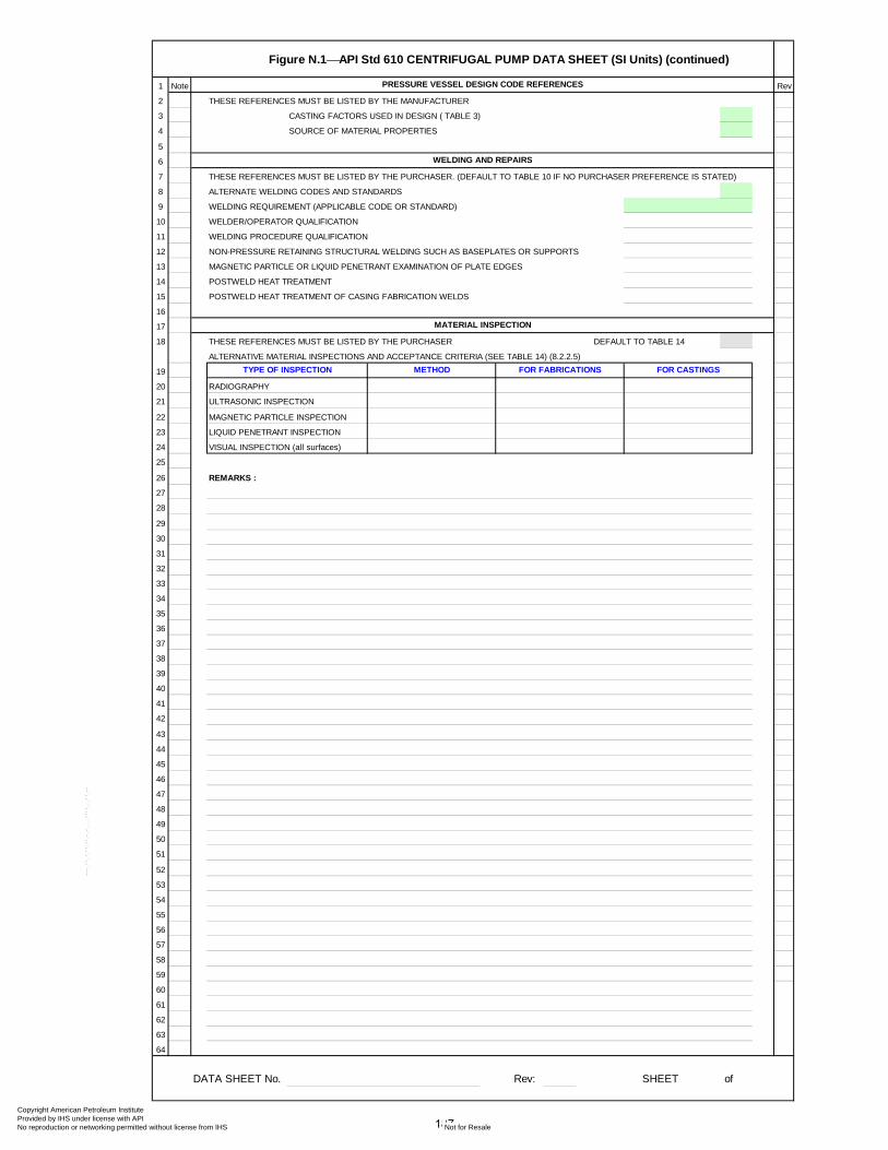
Figure N.1⎯API Std 610 CENTRIFUGAL PUMP DATA SHEET (SI Units) (continued)
1 Note Rev
2 THESE REFERENCES MUST BE LISTED BY THE MANUFACTURER
3 CASTING FACTORS USED IN DESIGN ( TABLE 3)
4 SOURCE OF MATERIAL PROPERTIES
5
6
7 THESE REFERENCES MUST BE LISTED BY THE PURCHASER. (DEFAULT TO TABLE 10 IF NO PURCHASER PREFERENCE IS STATED)
8 ALTERNATE WELDING CODES AND STANDARDS
9 WELDING REQUIREMENT (APPLICABLE CODE OR STANDARD)
10 WELDER/OPERATOR QUALIFICATION
11 WELDING PROCEDURE QUALIFICATION
12 NON-PRESSURE RETAINING STRUCTURAL WELDING SUCH AS BASEPLATES OR SUPPORTS
13 MAGNETIC PARTICLE OR LIQUID PENETRANT EXAMINATION OF PLATE EDGES
14 POSTWELD HEAT TREATMENT
15 POSTWELD HEAT TREATMENT OF CASING FABRICATION WELDS
16
17
18 THESE REFERENCES MUST BE LISTED BY THE PURCHASER DEFAULT TO TABLE 14
ALTERNATIVE MATERIAL INSPECTIONS AND ACCEPTANCE CRITERIA (SEE TABLE 14) (8.2.2.5)
19
20 RADIOGRAPHY
21 ULTRASONIC INSPECTION
22 MAGNETIC PARTICLE INSPECTION
23 LIQUID PENETRANT INSPECTION
24 VISUAL INSPECTION (all surfaces)
25
26 REMARKS :
27
28
29
30
31
32
33
34
35
36
37
38
39
40
41
42
43
44
45
46
47
48
49
50
51
52
53
54
55
56
57
58
59
60
61
62
63
64
DATA SHEET No. Rev: SHEET of
METHOD FOR FABRICATIONS FOR CASTINGS
PRESSURE VESSEL DESIGN CODE REFERENCES
WELDING AND REPAIRS
MATERIAL INSPECTION
TYPE OF INSPECTION
187
Copyright American Petroleum Institute Provided by IHS under license with API
Not for ResaleNo reproduction or networking permitted without license from IHS
--`,,```,,,,````-`-`,,`,,`,`,,`---

CLIENT:
PROJECT TITLE:
JOB NUMBER:
EQUIPMENT NUMBER:
EQUIPMENT SERVICE:
SERIAL NUMBER:
REQ / SPEC NO. : /
PURCH ORDER NO.
Cells coloured thus contain drop-down options
contain calculated values based on input data do not change.
identifies a cross referenced paraghaph in the documentnote may also contain a drop down list
When you have completed the DS highlight the whole page format cells pattern noneDelete these notes on completion
COMMENTS:
PUMP
MOTOR
GEAR
TURBINE
APPLICABLE OVERLAY STANDARDS
Rev Date Description
DATA SHEET No.
API Std 610 CENTRIFUGAL PUMP DATA SHEETFigure N.2 Sheet of
By Checked
ITEM No. ATT
CustomaryPROJECT UNITS
DATA SHEETSATTITEM No. ATTITEM No.
188
Copyright American Petroleum Institute Provided by IHS under license with API
Not for ResaleNo reproduction or networking permitted without license from IHS
--`,,```,,,,````-`-`,,`,,`,`,,`---
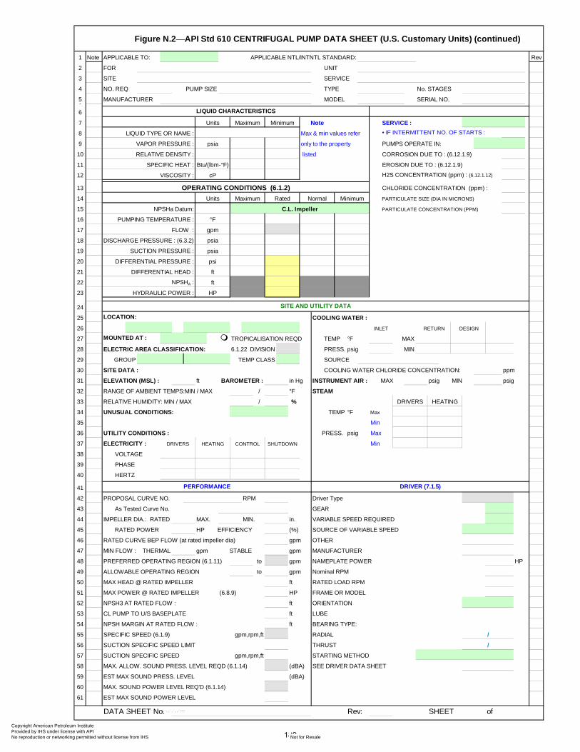
Figure N.2⎯API Std 610 CENTRIFUGAL PUMP DATA SHEET (U.S. Customary Units) (continued)
1 Note APPLICABLE TO: APPLICABLE NTL/INTNTL STANDARD: Rev
2 FOR UNIT
3 SITE SERVICE
4 NO. REQ PUMP SIZE TYPE No. STAGES
5 MANUFACTURER MODEL SERIAL NO.6
6
7 SERVICE :
8 LIQUID TYPE OR NAME : Max & min values refer • IF INTERMITTENT NO. OF STARTS :
9 VAPOR PRESSURE : only to the property PUMPS OPERATE IN:
10 listed CORROSION DUE TO : (6.12.1.9)
11 SPECIFIC HEAT : EROSION DUE TO : (6.12.1.9)
12 VISCOSITY : H2S CONCENTRATION (ppm) : (6.12.1.12)
13 CHLORIDE CONCENTRATION (ppm) :
14 PARTICULATE SIZE (DIA IN MICRONS)
15 NPSHa Datum: PARTICULATE CONCENTRATION (PPM)
16 PUMPING TEMPERATURE :
17 FLOW :
18 DISCHARGE PRESSURE : (6.3.2)
19 SUCTION PRESSURE :
20
21
22
23
24
25 LOCATION: COOLING WATER :
26
27 MOUNTED AT : TEMP °F MAX
28 ELECTRIC AREA CLASSIFICATION: 6.1.22 DIVISION PRESS. psig MIN
29 GROUP TEMP CLASS SOURCE
30 SITE DATA : COOLING WATER CHLORIDE CONCENTRATION: ppm
31 ELEVATION (MSL) : ft BAROMETER : in Hg INSTRUMENT AIR : MAX psig MIN psig
32 RANGE OF AMBIENT TEMPS:MIN / MAX / °F STEAM
33 RELATIVE HUMIDITY: MIN / MAX / %
34 UNUSUAL CONDITIONS: TEMP °F Max
35 Min
36 UTILITY CONDITIONS : PRESS. psig Max
37 ELECTRICITY : Min
38 VOLTAGE
39 PHASE
40 HERTZ
41
42 PROPOSAL CURVE NO. RPM Driver Type
43 As Tested Curve No. GEAR
44 IMPELLER DIA.: RATED MAX. MIN. in. VARIABLE SPEED REQUIRED
45 RATED POWER HP EFFICIENCY (%) SOURCE OF VARIABLE SPEED
46 RATED CURVE BEP FLOW (at rated impeller dia) gpm OTHER
47 MIN FLOW : THERMAL gpm STABLE gpm MANUFACTURER
48 PREFERRED OPERATING REGION (6.1.11) to gpm NAMEPLATE POWER HP
49 ALLOWABLE OPERATING REGION to gpm Nominal RPM
50 MAX HEAD @ RATED IMPELLER ft RATED LOAD RPM
51 MAX POWER @ RATED IMPELLER (6.8.9) HP FRAME OR MODEL
52 NPSH3 AT RATED FLOW : ft ORIENTATION
53 CL PUMP TO U/S BASEPLATE ft LUBE
54 NPSH MARGIN AT RATED FLOW : ft BEARING TYPE:
55 SPECIFIC SPEED (6.1.9) gpm,rpm,ft RADIAL
56 SUCTION SPECIFIC SPEED LIMIT THRUST
57 SUCTION SPECIFIC SPEED gpm,rpm,ft STARTING METHOD
58 MAX. ALLOW. SOUND PRESS. LEVEL REQD (6.1.14) (dBA) SEE DRIVER DATA SHEET
59 EST MAX SOUND PRESS. LEVEL (dBA)
60 MAX. SOUND POWER LEVEL REQ'D (6.1.14)
61 EST MAX SOUND POWER LEVEL
DATA SHEET No. Rev: SHEET of
gpm
psia
/
/
DRIVER (7.1.5)PERFORMANCE
Units NoteMaximum
LIQUID CHARACTERISTICS
RELATIVE DENSITY :
cP
OPERATING CONDITIONS (6.1.2)
Btu/(lbm-°F)
Minimum
DIFFERENTIAL PRESSURE : psi
DIFFERENTIAL HEAD :
psia
DESIGN
Units Normal
ft
psia
°F
Minimum
NPSHA :
HYDRAULIC POWER :
ft
HP
SITE AND UTILITY DATA
HEATINGDRIVERS CONTROL SHUTDOWN
RETURN
TROPICALISATION REQD
INLET
HEATINGDRIVERS
C.L. Impeller
Maximum Rated
189
Copyright American Petroleum Institute Provided by IHS under license with API
Not for ResaleNo reproduction or networking permitted without license from IHS
--`,,```,,,,````-`-`,,`,,`,`,,`---
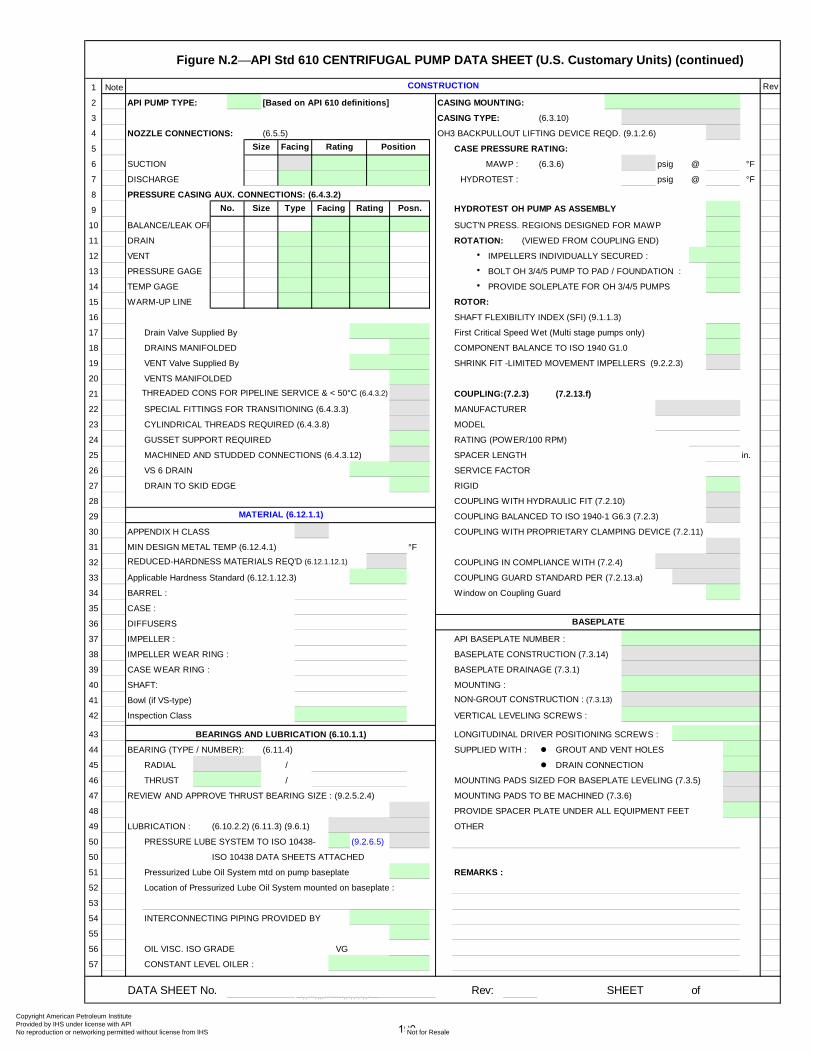
Figure N.2⎯API Std 610 CENTRIFUGAL PUMP DATA SHEET (U.S. Customary Units) (continued)
1 Note Rev
2 API PUMP TYPE: [Based on API 610 definitions] CASING MOUNTING:
3 CASING TYPE: (6.3.10)
4 NOZZLE CONNECTIONS: (6.5.5) OH3 BACKPULLOUT LIFTING DEVICE REQD. (9.1.2.6)
5 CASE PRESSURE RATING:
6 SUCTION MAWP : (6.3.6) psig @ °F
7 DISCHARGE HYDROTEST : psig @ °F
8 PRESSURE CASING AUX. CONNECTIONS: (6.4.3.2)
9 HYDROTEST OH PUMP AS ASSEMBLY
10 BALANCE/LEAK OFF SUCT'N PRESS. REGIONS DESIGNED FOR MAWP
11 DRAIN ROTATION: (VIEWED FROM COUPLING END)
12 VENT • IMPELLERS INDIVIDUALLY SECURED :
13 PRESSURE GAGE • BOLT OH 3/4/5 PUMP TO PAD / FOUNDATION :
14 TEMP GAGE • PROVIDE SOLEPLATE FOR OH 3/4/5 PUMPS
15 WARM-UP LINE ROTOR:
16 SHAFT FLEXIBILITY INDEX (SFI) (9.1.1.3)
17 Drain Valve Supplied By First Critical Speed Wet (Multi stage pumps only)
18 DRAINS MANIFOLDED COMPONENT BALANCE TO ISO 1940 G1.0
19 VENT Valve Supplied By SHRINK FIT -LIMITED MOVEMENT IMPELLERS (9.2.2.3)
20 VENTS MANIFOLDED
21 THREADED CONS FOR PIPELINE SERVICE & < 50°C (6.4.3.2) COUPLING:(7.2.3) (7.2.13.f)
22 SPECIAL FITTINGS FOR TRANSITIONING (6.4.3.3) MANUFACTURER
23 CYLINDRICAL THREADS REQUIRED (6.4.3.8) MODEL
24 GUSSET SUPPORT REQUIRED RATING (POWER/100 RPM)
25 MACHINED AND STUDDED CONNECTIONS (6.4.3.12) SPACER LENGTH in.
26 VS 6 DRAIN SERVICE FACTOR
27 DRAIN TO SKID EDGE RIGID
28 COUPLING WITH HYDRAULIC FIT (7.2.10)
29 COUPLING BALANCED TO ISO 1940-1 G6.3 (7.2.3)
30 APPENDIX H CLASS COUPLING WITH PROPRIETARY CLAMPING DEVICE (7.2.11)
31 MIN DESIGN METAL TEMP (6.12.4.1) °F
32 REDUCED-HARDNESS MATERIALS REQ'D (6.12.1.12.1) COUPLING IN COMPLIANCE WITH (7.2.4)
33 Applicable Hardness Standard (6.12.1.12.3) COUPLING GUARD STANDARD PER (7.2.13.a)
34 BARREL : Window on Coupling Guard
35 CASE :
36 DIFFUSERS
37 IMPELLER : API BASEPLATE NUMBER :
38 IMPELLER WEAR RING : BASEPLATE CONSTRUCTION (7.3.14)
39 CASE WEAR RING : BASEPLATE DRAINAGE (7.3.1)
40 SHAFT: MOUNTING :
41 Bowl (if VS-type) NON-GROUT CONSTRUCTION : (7.3.13)
42 Inspection Class VERTICAL LEVELING SCREWS :
43 LONGITUDINAL DRIVER POSITIONING SCREWS :
44 BEARING (TYPE / NUMBER): (6.11.4) SUPPLIED WITH : GROUT AND VENT HOLES
45 RADIAL / DRAIN CONNECTION
46 THRUST / MOUNTING PADS SIZED FOR BASEPLATE LEVELING (7.3.5)
47 REVIEW AND APPROVE THRUST BEARING SIZE : (9.2.5.2.4) MOUNTING PADS TO BE MACHINED (7.3.6)
48 PROVIDE SPACER PLATE UNDER ALL EQUIPMENT FEET
49 LUBRICATION : (6.10.2.2) (6.11.3) (9.6.1) OTHER
50 PRESSURE LUBE SYSTEM TO ISO 10438- (9.2.6.5)
50 ISO 10438 DATA SHEETS ATTACHED
51 Pressurized Lube Oil System mtd on pump baseplate REMARKS :
52 Location of Pressurized Lube Oil System mounted on baseplate :
53
54 INTERCONNECTING PIPING PROVIDED BY
55
56 OIL VISC. ISO GRADE VG
57 CONSTANT LEVEL OILER :
DATA SHEET No. Rev: SHEET of
CONSTRUCTION
BEARINGS AND LUBRICATION (6.10.1.1)
Facing Rating
BASEPLATE
No.
MATERIAL (6.12.1.1)
Facing
TypeSize
Size Position
Posn.
Rating
190
Copyright American Petroleum Institute Provided by IHS under license with API
Not for ResaleNo reproduction or networking permitted without license from IHS
--`,,```,,,,````-`-`,,`,,`,`,,`---
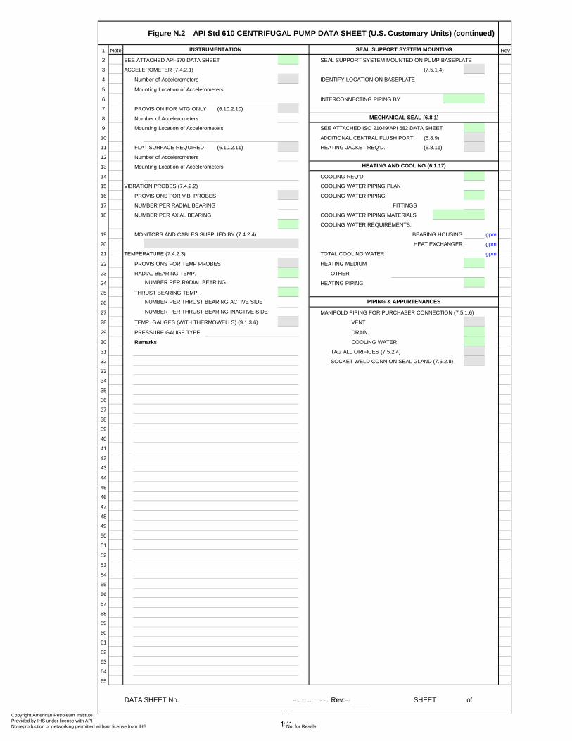
Figure N.2⎯API Std 610 CENTRIFUGAL PUMP DATA SHEET (U.S. Customary Units) (continued)
1 Note Rev
2 SEE ATTACHED API-670 DATA SHEET SEAL SUPPORT SYSTEM MOUNTED ON PUMP BASEPLATE
3 ACCELEROMETER (7.4.2.1) (7.5.1.4)
4 Number of Accelerometers IDENTIFY LOCATION ON BASEPLATE
5 Mounting Location of Accelerometers
6 INTERCONNECTING PIPING BY
7 PROVISION FOR MTG ONLY (6.10.2.10)
8 Number of Accelerometers
9 Mounting Location of Accelerometers SEE ATTACHED ISO 21049/API 682 DATA SHEET
10 ADDITIONAL CENTRAL FLUSH PORT (6.8.9)
11 FLAT SURFACE REQUIRED (6.10.2.11) HEATING JACKET REQ'D. (6.8.11)
12 Number of Accelerometers
13 Mounting Location of Accelerometers
14 COOLING REQ'D
15 VIBRATION PROBES (7.4.2.2) COOLING WATER PIPING PLAN
16 PROVISIONS FOR VIB. PROBES COOLING WATER PIPING
17 NUMBER PER RADIAL BEARING FITTINGS
18 NUMBER PER AXIAL BEARING COOLING WATER PIPING MATERIALS
COOLING WATER REQUIREMENTS:
19 MONITORS AND CABLES SUPPLIED BY (7.4.2.4) BEARING HOUSING gpm
20 HEAT EXCHANGER gpm
21 TEMPERATURE (7.4.2.3) TOTAL COOLING WATER gpm
22 PROVISIONS FOR TEMP PROBES HEATING MEDIUM
23 RADIAL BEARING TEMP. OTHER
24 NUMBER PER RADIAL BEARING HEATING PIPING
25 THRUST BEARING TEMP.
26 NUMBER PER THRUST BEARING ACTIVE SIDE
27 NUMBER PER THRUST BEARING INACTIVE SIDE MANIFOLD PIPING FOR PURCHASER CONNECTION (7.5.1.6)
28 TEMP. GAUGES (WITH THERMOWELLS) (9.1.3.6) VENT
29 PRESSURE GAUGE TYPE DRAIN
30 Remarks COOLING WATER
31 TAG ALL ORIFICES (7.5.2.4)
32 SOCKET WELD CONN ON SEAL GLAND (7.5.2.8)
33
34
35
36
37
38
39
40
41
42
43
44
45
46
47
48
49
50
51
52
53
54
55
56
57
58
59
60
61
62
63
64
65
DATA SHEET No. Rev: SHEET of
INSTRUMENTATION SEAL SUPPORT SYSTEM MOUNTING
PIPING & APPURTENANCES
MECHANICAL SEAL (6.8.1)
HEATING AND COOLING (6.1.17)
191
Copyright American Petroleum Institute Provided by IHS under license with API
Not for ResaleNo reproduction or networking permitted without license from IHS
--`,,```,,,,````-`-`,,`,,`,`,,`---
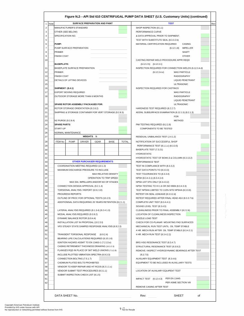
Figure N.2⎯API Std 610 CENTRIFUGAL PUMP DATA SHEET (U.S. Customary Units) (continued)
1 Note Rev
2 MANUFACTURER'S STANDARD SHOP INSPECTION (8.1.1)
3 OTHER (SEE BELOW) PERFORMANCE CURVE
4 SPECIFICATION NO. & DATA APPROVAL PRIOR TO SHIPMENT.
5 TEST WITH SUBSTITUTE SEAL (8.3.3.2.b)
6 PUMP: MATERIAL CERTIFICATION REQUIRED CASING
7 PUMP SURFACE PREPARATION (6.12.1.8) IMPELLER
8 PRIMER SHAFT
9 FINISH COAT OTHER
10 CASTING REPAIR WELD PROCEDURE APPR REQD
BASEPLATE: (6.12.2.5) (6.12.3.1)
11 BASEPLATE SURFACE PREPARATION INSPECTION REQUIRED FOR CONNECTION WELDS (6.12.3.4.d)
12 PRIMER: (6.12.3.4.e) MAG PARTICLE
13 FINISH COAT RADIOGRAPHY
14 DETAILS OF LIFTING DEVICES LIQUID PENETRANT
15 ULTRASONIC
16 SHIPMENT: (8.4.1) INSPECTION REQUIRED FOR CASTINGS
17 EXPORT BOXING REQUIRED MAG PARTICLE
18 OUTDOOR STORAGE MORE THAN 6 MONTHS RADIOGRAPHY
LIQUID PENETRANT
19 SPARE ROTOR ASSEMBLY PACKAGED FOR: ULTRASONIC
20 ROTOR STORAGE ORIENTATION (9.2.8.2) HARDNESS TEST REQUIRED (8.2.2.7)
21 SHIPPING & STORAGE CONTAINER FOR VERT STORAGE (9.2.8.3) ADDNL SUBSURFACE EXAMINATION (6.12.1.5) (8.2.1.3)
22 FOR
23 N2 PURGE (9.2.8.4) METHOD
24 SPARE PARTS PMI TESTING REQUIRED (8.2.2.8)
25 START-UP COMPONENTS TO BE TESTED
26 NORMAL MAINTENANCE
27 WEIGHTS lb RESIDUAL UNBALANCE TEST (J.4.1.2)
28 NOTIFICATION OF SUCCESSFUL SHOP
29 PERFORMANCE TEST (8.1.1.c) (8.3.3.5)
30 BASEPLATE TEST (7.3.21)
31 HYDROSTATIC
32 HYDROSTATIC TEST OF BOWLS & COLUMN (9.3.13.2)
33 PERFORMANCE TEST
34 COORDINATION MEETING REQUIRED (10.1.3) TEST IN COMPLIANCE WITH (8.3.3.2)
35 MAXIMUM DISCHARGE PRESSURE TO INCLUDE TEST DATA POINTS TO (8.3.3.3)
36 MAX RELATIVE DENSITY TEST TOLERANCES TO (8.3.3.4)
37 OPERATION TO TRIP SPEED NPSH (8.3.4.3.1) (8.3.4.3.4)
38 MAX DIA. IMPELLERS AND/OR NO OF STAGES NPSH-1ST STG ONLY (8.3.4.3.2)
39 CONNECTION DESIGN APPROVAL (9.2.1.4) NPSH TESTING TO HI 1.6 OR ISO 9906 (8.3.4.3.3)
40 TORSIONAL ANALYSIS / REPORT (6.9.2.10) TEST NPSHA LIMITED TO 110% SITE NPSHA (8.3.3.6)
41 PROGRESS REPORTS RETEST ON SEAL LEAKAGE (8.3.3.2.d)
42 OUTLINE OF PROC FOR OPTIONAL TESTS (10.2.5) RETEST REQUIRED AFTER FINAL HEAD ADJ (8.3.3.7.b)
43 ADDITIONNAL DATA REQUIRING 20 YEARS RETENTION (8.2.1.1) COMPLETE UNIT TEST (8.3.4.4.1)
44 SOUND LEVEL TEST (8.3.4.5)
45 LATERAL ANALYSIS REQUIRED (9.1.3.4) (9.2.4.1.3) CLEANLINESS PRIOR TO FINAL ASSEMBLY (8.2.2.6)
46 MODAL ANALYSIS REQUIRED (9.3.9.2) LOCATION OF CLEANLINESS INSPECTION
47 DYNAMIC BALANCE ROTOR (6.9.4.4) NOZZLE LOAD TEST
48 INSTALLATION LIST IN PROPOSAL (10.2.3.l) CHECK FOR CO-PLANAR MOUNTING PAD SURFACES
49 VFD STEADY STATE DAMPED RESPONSE ANALYSIS (6.9.2.3) MECHANICAL RUN TEST UNTIL OIL TEMP STABLE
50 4 HR. MECH RUN AFTER OIL TEMP STABLE (8.3.4.2.1)
51 TRANSIENT TORSIONAL RESPONSE (6.9.2.4) 4 HR. MECH RUN TEST (8.3.4.2.2)
52 BEARING LIFE CALCULATIONS REQUIRED (6.10.1.6)
IGNITION HAZARD ASSMT TO EN 13463-1 (7.2.13.e) BRG HSG RESONANCE TEST (8.3.4.7)
53 CASING RETIREMENT THICKNESS DRAWING (10.3.2.3) STRUCTURAL RESONANCE TEST (9.3.9.2)
54 FLANGES RQD IN PLACE OF SKT WELD UNIONS (7.5.2.8) REMOVE / INSPECT HYDRODYNAMIC BEARINGS AFTER TEST
55 INCLUDE PLOTTED VIBRATION SPECTRA (6.9.3.3) (9.2.7.5)
56 CONNECTION BOLTING (7.5.1.7) AUXILIARY EQUIPMENT TEST (8.3.4.6)
57 CADMIUM PLATED BOLTS PROHIBITED EQUIPMENT TO BE INCLUDED IN AUXILLIARY TESTS
58 VENDOR TO KEEP REPAIR AND HT RCDS (8.2.1.1.c)
59 VENDOR SUBMIT TEST PROCEDURES (8.3.1.1) LOCATION OF AUXILIARY EQUIPENT TEST
60 SUBMIT INSPECTION CHECK LIST (8.1.5)
61 IMPACT TEST (6.12.4.3) PER EN 13445
62 PER ASME SECTION VIII
REMOVE CASING AFTER TEST
DATA SHEET No. Rev: SHEET of
OTHER PURCHASER REQUIREMENTS
TESTSURFACE PREPARATION AND PAINT
ITEM No PUMP DRIVER BASEGEAR TOTAL
192
Copyright American Petroleum Institute Provided by IHS under license with API
Not for ResaleNo reproduction or networking permitted without license from IHS
--`,,```,,,,````-`-`,,`,,`,`,,`---
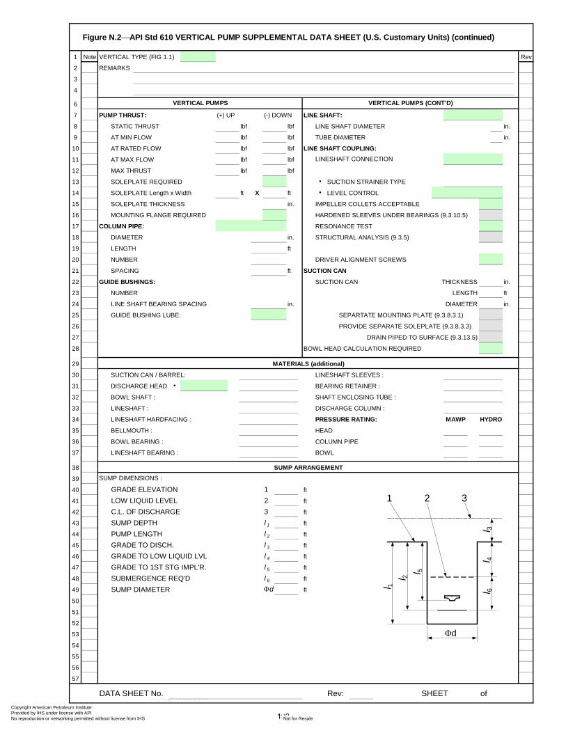
Figure N.2⎯API Std 610 VERTICAL PUMP SUPPLEMENTAL DATA SHEET (U.S. Customary Units) (continued)
1 Note VERTICAL TYPE (FIG 1.1) Rev
2 REMARKS
3
4
6
7 PUMP THRUST: (+) UP (-) DOWN LINE SHAFT:
8 STATIC THRUST lbf lbf LINE SHAFT DIAMETER in.
9 AT MIN FLOW lbf lbf TUBE DIAMETER in.
10 AT RATED FLOW lbf lbf LINE SHAFT COUPLING:
11 AT MAX FLOW lbf lbf LINESHAFT CONNECTION
12 MAX THRUST lbf lbf
13 SOLEPLATE REQUIRED • SUCTION STRAINER TYPE
14 SOLEPLATE Length x Width ft X ft • LEVEL CONTROL
15 SOLEPLATE THICKNESS in. IMPELLER COLLETS ACCEPTABLE
16 MOUNTING FLANGE REQUIRED HARDENED SLEEVES UNDER BEARINGS (9.3.10.5)
17 COLUMN PIPE: RESONANCE TEST
18 DIAMETER in. STRUCTURAL ANALYSIS (9.3.5)
19 LENGTH ft
20 NUMBER DRIVER ALIGNMENT SCREWS
21 SPACING ft SUCTION CAN
22 GUIDE BUSHINGS: SUCTION CAN THICKNESS in.
23 NUMBER LENGTH ft
24 LINE SHAFT BEARING SPACING in. DIAMETER in.
25 GUIDE BUSHING LUBE: SEPARTATE MOUNTING PLATE (9.3.8.3.1)
26 PROVIDE SEPARATE SOLEPLATE (9.3.8.3.3)
27 DRAIN PIPED TO SURFACE (9.3.13.5)
28 BOWL HEAD CALCULATION REQUIRED
29
30 SUCTION CAN / BARREL: LINESHAFT SLEEVES :
31 DISCHARGE HEAD • BEARING RETAINER :
32 BOWL SHAFT : SHAFT ENCLOSING TUBE :
33 LINESHAFT : DISCHARGE COLUMN :
34 LINESHAFT HARDFACING : PRESSURE RATING:
35 BELLMOUTH : HEAD
36 BOWL BEARING : COLUMN PIPE
37 LINESHAFT BEARING : BOWL
38
39 SUMP DIMENSIONS :
40 GRADE ELEVATION 1 ft
41 LOW LIQUID LEVEL 2 ft
42 C.L. OF DISCHARGE 3 ft
43 SUMP DEPTH l 1 ft
44 PUMP LENGTH l 2 ft
45 GRADE TO DISCH. l 3 ft
46 GRADE TO LOW LIQUID LVL l 4 ft
47 GRADE TO 1ST STG IMPL'R. l 5 ft
48 SUBMERGENCE REQ'D l 6 ft
49 SUMP DIAMETER Φd ft
50
51
52
53 Φd54
55
56
57
DATA SHEET No. Rev: SHEET of
MAWP HYDRO
SUMP ARRANGEMENT
MATERIALS (additional)
VERTICAL PUMPS VERTICAL PUMPS (CONT'D)
l 1l 2 l 5
l 3l 4
l 61 2 3
193
Copyright American Petroleum Institute Provided by IHS under license with API
Not for ResaleNo reproduction or networking permitted without license from IHS
--`,,```,,,,````-`-`,,`,,`,`,,`---
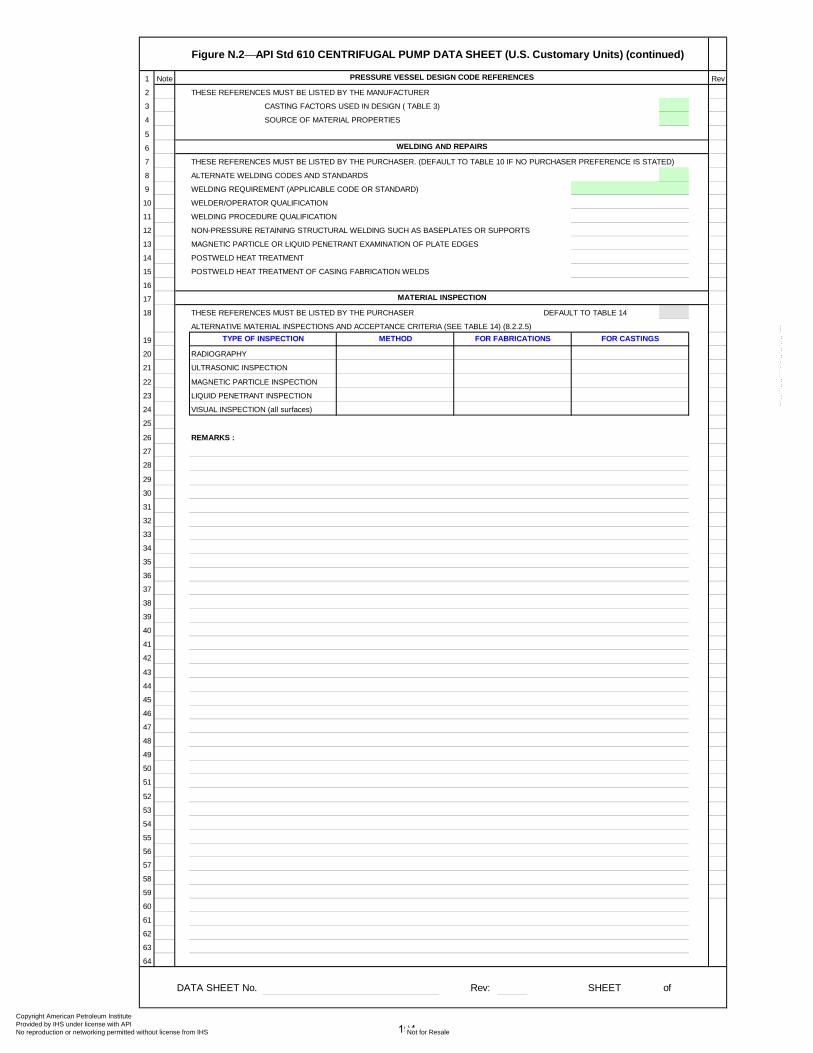
Figure N.2⎯API Std 610 CENTRIFUGAL PUMP DATA SHEET (U.S. Customary Units) (continued)
1 Note Rev
2 THESE REFERENCES MUST BE LISTED BY THE MANUFACTURER
3 CASTING FACTORS USED IN DESIGN ( TABLE 3)
4 SOURCE OF MATERIAL PROPERTIES
5
6
7 THESE REFERENCES MUST BE LISTED BY THE PURCHASER. (DEFAULT TO TABLE 10 IF NO PURCHASER PREFERENCE IS STATED)
8 ALTERNATE WELDING CODES AND STANDARDS
9 WELDING REQUIREMENT (APPLICABLE CODE OR STANDARD)
10 WELDER/OPERATOR QUALIFICATION
11 WELDING PROCEDURE QUALIFICATION
12 NON-PRESSURE RETAINING STRUCTURAL WELDING SUCH AS BASEPLATES OR SUPPORTS
13 MAGNETIC PARTICLE OR LIQUID PENETRANT EXAMINATION OF PLATE EDGES
14 POSTWELD HEAT TREATMENT
15 POSTWELD HEAT TREATMENT OF CASING FABRICATION WELDS
16
17
18 THESE REFERENCES MUST BE LISTED BY THE PURCHASER DEFAULT TO TABLE 14
ALTERNATIVE MATERIAL INSPECTIONS AND ACCEPTANCE CRITERIA (SEE TABLE 14) (8.2.2.5)
19
20 RADIOGRAPHY
21 ULTRASONIC INSPECTION
22 MAGNETIC PARTICLE INSPECTION
23 LIQUID PENETRANT INSPECTION
24 VISUAL INSPECTION (all surfaces)
25
26 REMARKS :
27
28
29
30
31
32
33
34
35
36
37
38
39
40
41
42
43
44
45
46
47
48
49
50
51
52
53
54
55
56
57
58
59
60
61
62
63
64
DATA SHEET No. Rev: SHEET of
METHOD FOR FABRICATIONS FOR CASTINGS
PRESSURE VESSEL DESIGN CODE REFERENCES
WELDING AND REPAIRS
MATERIAL INSPECTION
TYPE OF INSPECTION
194
Copyright American Petroleum Institute Provided by IHS under license with API
Not for ResaleNo reproduction or networking permitted without license from IHS
--`,,```,,,,````-`-`,,`,,`,`,,`---
Figure N.3⎯CENTRIFUGAL PUMP DATA SHEET
1 Note PROPOSAL, PURCHASE, AS-BUILT Rev
2
3
4
56
6
7 CONTINUOUS, INTERMITTENT
8
9 PARALLEL, SERIES
10
11
12
13
14
15 6.1.2 C.L. IMPELLER, TOP OF FOUNDATION
16
17
18
19
20
21
22
23
24
25
26 INDOOR, OUTDOOR HEATED, UNHEATED UNDER ROOF
27 GRADE, MEZANINE PARTIAL SIDES
28 6.1.22 0, 1, 2, SAFE
29 Group Temp Class
30 CLASS I/GROUP A T1 T3B
31 CLASS I/GROUP B T2 T3C
32 CLASS I/GROUP C T2A T4
33 CLASS I/GROUP D T2B T4A
34 MINING T2C T5
35 CLASS II/GROUP E Conditions T2D T6
36 CLASS II/GROUP F DUST T3
37 CLASS II/GROUP G FUMES T3A
38 CLASS III DUST & FUMES T3B
39 OTHER T3C
40
41
42
43 YES, NO
44 YES, NO
45 MOTOR, GEAR COUPLING, OTHER
46
47
48
49
50
51
52 HORIZONTAL, VERTICAL
53
54
55
56
57 OPEN VAVE (FULLY-LOADED)
58 CLOSED-VALVE (UNLOADED) START
59
60
61
DATA SHEET No. Rev: SHEET of
SITE AND UTILITY DATA
DRIVER (7.1.5)PERFORMANCE
LIQUID CHARACTERISTICS
OPERATING CONDITIONS (6.1.2)
195
Copyright American Petroleum Institute Provided by IHS under license with API
Not for ResaleNo reproduction or networking permitted without license from IHS
--`,,```,,,,````-`-`,,`,,`,`,,`---
Figure N.3⎯CENTRIFUGAL PUMP DATA SHEET (continued)
1 Note Rev
2 OH1, OH2, OH3, OH4, OH5, OH6, BB1, BB2, BB3, BB4, BB5, CENTERLINE, FOOT, IN-LINE, NEAR CENTERLINE, VERTICAL
3 VS1, VS2, VS3, VS4, VS5, VS6, VS7 SUMP COVER PLATE, SEPARATE MOUNTING PLATE, SEPARATE SOLE PLATE
4 6.5.5 Facing Rating Position 6.3.10 SINGLE VOLUTE, MULTIPLE VOLUTE, DIFFUSER5 FF 150 END 9.1.2.6 YES, NO6 RF 300 TOP7 RTJ 600 SIDE8 900 IN-LINE9 1500 BOTTOM YES, NO
10 BELL YES, NO
11 6.4.3.2 Type Facing Rating Position CCW, CW
12 SW FF TOP YES, NOT, BOTH DIRECTIONS
13 SWF RF SIDE YES, NO
14 RTJ IN-LINE YES, NO
15
16
17 SUPPLIER, PURCHASER 9.1.1.3 YES, NO, N/A
18 YES, NO YES, NO, N/A
19 SUPPLIER, PURCHASER 9.2.2.3 YES, NO, N/A
20 YES, NO
21 6.4.3.2 YES, NO
22 6.4.3.3 YES, NO
23 6.4.3.8 YES, NO
24 YES, NO
25 6.4.3.12 YES, NO
26 INTERNAL, EXTERNAL, N/A
27 YES, NO YES, NO N/A
28 7.2.10 YES, NO N/A29 7.2.3 YES, NO N/A30 I-1, I-2, S-1, S-2, S-3, S-4, S-5, S-6, S-7, S-8, S-9, C-6, A-7, A-8, D-131 7.2.11 YES, NO, N/A32 6.12.1.12.1 YES, NO 7.2.4 ISO 14691, ISO 10441, API 671, API 610 COMPLIANT, MFR STD33 6.12.1.12.3 NA, ISO 15156, MR0103, MR0175 7.2.13.A ISO 14120, EN 953, ANSI B16.134 YES, NO, N/A3536
37 0.5, 1, 1.5, 2, 3, 3.5, 4, 5, 5.5, 6, 6.5, 7, 7.5, 8, 9, 9.5, 10, 11, 11.5, 12, N/A
387.3.14
397.3.1
40
41 LEVEL 1, LEVEL 2, LEVEL 3 7.3.13 NOT REQUIRED, REQUIRED42 REQUIRED, NOT REQUIRED
43 REQUIRED, NOT REQUIRED44 YES, NO45 6.11.4 BALL, ROLLER, SLEEVE, TILT PAD YES, NO46 6.11.4 BALL, ROLLER, SLEEVE, TILT PAD 7.3.5 YES, NO47 9.2.5.2.4 YES, NO 7.3.6 YES, NO48 GREASE, FLOOD, RING OIL, FLINGER, PRESSURE LUBE YES, NO
49 PURGE OIL MIST, PURE OIL MIST
50 2, 3 (9.2.6.5) YES, NO
50
51 YES, NO5253
54 PURCHASER, SUPPLIER5556
57 REQUIRED, NOT REQUIRED
DATA SHEET No. Rev: SHEET of
CONSTRUCTION
BASEPLATE
1251502503006009001500
OPEN BEAM SUPPORT, FULL TOP DECKING, PARTIAL TOP DECKING, OPEN DECKING
ENTIRE BASEPLATE DRAIN RIM, ENTIRE BASEPLATE DRAIN PAN, PARTIAL DRAIN PAN
MATERIAL (6.12.1.1)
BEARINGS AND LUBRICATION (6.10.1.1)
GROUTED, BOLTED ON STEEL WORK, THREE POINT MOUNT, FOUR POINT MOUNT, STILT MOUNTED
196
Copyright American Petroleum Institute Provided by IHS under license with API
Not for ResaleNo reproduction or networking permitted without license from IHS
--`,,```,,,,````-`-`,,`,,`,`,,`---
Figure N.3⎯CENTRIFUGAL PUMP DATA SHEET (continued)
1 Note Rev
2 YES, NO, N/A
3 7.5.1.4 YES, NO, N/A
4
5
6 PURCHASER, SUPPLLIER
7 6.10.2.10 YES, NO, N/A
8
9 YES, NO, N/A
10 6.8.9 YES, NO, N/A
11 6.10.2.11 YES, NO, N/A 6.8.11 YES, NO, N/A
12
13
14 YES, NO, N/A
15
16 7.4.2.2 YES, NO, N/A PIPE, TUBE
17
18 CS, GALVANIZED, STAINLESS STEEL
YES, NO, N/A
19
20
21
22 7.4.2.3 YES, NO, N/A STEAM, OTHER
23 YES, NO, N/A
24 PIPE, TUBE
25 YES, NO, N/A
26
27
28 9.1.3.6 YES, NO, N/A YES, NO, N/A
29 YES, NO, N/A
30 YES, NO, N/A
31 7.5.2.4 YES, NO, N/A
32 7.5.2.8 YES, NO, N/A
33
34
35
36
37
38
39
40
41
42
43
44
45
46
47
48
49
50
51
52
53
54
55
56
57
58
59
60
61
62
63
64
65
DATA SHEET No. Rev: SHEET of
INSTRUMENTATION SEAL SUPPORT SYSTEM MOUNTING
PIPING & APPURTENANCES
MECHANICAL SEAL (6.8.1)
HEATING AND COOLING (6.1.17)
197
Copyright American Petroleum Institute Provided by IHS under license with API
Not for ResaleNo reproduction or networking permitted without license from IHS
--`,,```,,,,````-`-`,,`,,`,`,,`---
Figure N.3⎯CENTRIFUGAL PUMP DATA SHEET (continued)
1 Note Rev
2 YES, NO 8.1.1 YES, NO
3 YES, NO
4 YES, NO
5 8.3.3.2.B YES, NO
6 YES, NO
7 6.12.1.8 YES, NO
8 YES, NO
9 YES, NO
10 YES, NO
6.1.12.2.5, 6.12.3.1
11
12 6.12.3.4.E YES, NO
13 YES, NO
14 YES, NO
15 YES, NO
16 8.4.1 DOMESTIC, EXPORT
17 YES, NO YES, NO
18 YES, NO YES, NO
YES, NO
19 YES, NO
20 9.2.8.2 HORIZONTAL, VERTICAL 8.2.2.7 YES, NO
21 6.12.1.5, 8.2.1.3 YES, NO
22 YES, NON
23 YES, NON
24 8.2.2.8 YES, NO
25 YES, NO
26 YES, NO
27 WEIGHTS J.4.1.2 YES, NO
28
29 8.1.1.C, 8.3.3.5 YES, NO
30 7.3.21 YES, NO
31 NON-WIT, WIT, OBSERVE
32 9.3.13.2 NON-WIT, WIT, OBSERVE
33 NON-WIT, WIT, OBSERVE
34 10.1.3 YES, NO 8.3.3.2 8.3.3.2, MFR STD
35 8.3.3.3 8.3.3.3, MFR STD
36 YES, NO 8.3.3.4 TABLE 15, AGREED LIMITS
37 YES, NO 8.3.4.3.1, 8.3.4.3.4 NON-WIT, WIT, OBSERVE
38 YES, NO 8.3.4.3.2 NON-WIT, WIT, OBSERVE
39 9.2.1.4 YES, NO 8.3.4.3.3 NON-WIT, WIT, OBSERVE
40 6.9.2.10 YES, NO 8.3.3.6 YES, NO
41 YES, NO 8.3.3.2.D NON-WIT, WIT, OBSERVE
42 10.2.5 YES, NO 8.3.3.7.B NON-WIT, WIT, OBSERVE
43 8.2.1.1 8.3.4.4.1 NON-WIT, WIT, OBSERVE
44 YES, NO 8.3.4.5 NON-WIT, WIT, OBSERVE
45 9.1.3.4, 9.2.4.1.3 YES, NO 8.2.2.6 NON-WIT, WIT, OBSERVE
46 9.3.9.2 YES, NO @ SUPPLIER'S, @ SUB-SUPPLIER'S
47 6.9.4.4 YES, NO NON-WIT, WIT, OBSERVE
48 10.2.3.I YES, NO NON-WIT, WIT, OBSERVE
49 NON-WIT, WIT, OBSERVE
50 6.9.2.3 YES, NO 8.3.4.2.1 NON-WIT, WIT, OBSERVE
51 6.9.2.4 YES, NO 8.3.4.2.2 NON-WIT, WIT, OBSERVE
52 6.10.1.6 YES, NO
7.2.13.e YES, NO 8.3.4.7 NON-WIT, WIT, OBSERVE
53 10.3.2.3 YES, NO 9.3.9.2 NON-WIT, WIT, OBSERVE
54 7.5.2.8 YES, NO
55 6.9.3.3 YES, NO 9.2.7.5 NON-WIT, WIT, OBSERVE
56 7.5.1.7 PTFE COATED, ASTM 153 GAVVANIZED, PAINTED, SS 8.3.4.6 NON-WIT, WIT, OBSERVE
57 YES, NO
58 8.2.1.1.C YES, NO
59 8.3.11 YES, NO
60 8.1.5 YES, NO
61 6.12.4.3 NON-WIT, WIT, OBSERVE
62 NON-WIT, WIT, OBSERVE
NON-WIT, WIT, OBSERVE
DATA SHEET No. Rev: SHEET of
OTHER PURCHASER REQUIREMENTS
TESTSURFACE PREPARATION AND PAINT
198
Copyright American Petroleum Institute Provided by IHS under license with API
Not for ResaleNo reproduction or networking permitted without license from IHS
--`,,```,,,,````-`-`,,`,,`,`,,`---
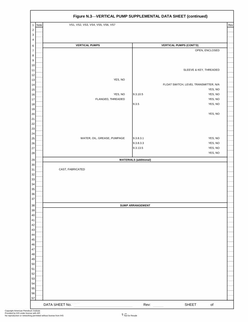
Figure N.3⎯VERTICAL PUMP SUPPLEMENTAL DATA SHEET (continued)
1 Note VS1, VS2, VS3, VS4, VS5, VS6, VS7 Rev
2
3
4
6
7 OPEN, ENCLOSED
8
9
10
11 SLEEVE & KEY, THREADED
12
13 YES, NO
14 FLOAT SWITCH, LEVEL TRANSMITTER, N/A
15 YES, NO
16 YES, NO 9.3.10.5 YES, NO
17 FLANGED, THREADED YES, NO
18 9.3.5 YES, NO
19
20 YES, NO
21
22
23
24
25 WATER, OIL, GREASE, PUMPAGE 9.3.8.3.1 YES, NO
26 9.3.8.3.3 YES, NO
27 9.3.13.5 YES, NO
28 YES, NO
29
30
31 CAST, FABRICATED
32
33
34
35
36
37
38
39
40
41
42
43
44
45
46
47
48
49
50
51
52
53
54
55
56
57
DATA SHEET No. Rev: SHEET of
VERTICAL PUMPS VERTICAL PUMPS (CONT'D)
SUMP ARRANGEMENT
MATERIALS (additional)
199
Copyright American Petroleum Institute Provided by IHS under license with API
Not for ResaleNo reproduction or networking permitted without license from IHS
--`,,```,,,,````-`-`,,`,,`,`,,`---
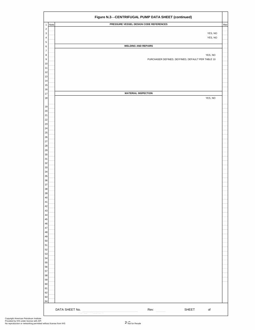
Figure N.3⎯CENTRIFUGAL PUMP DATA SHEET (continued)
1 Note Rev
2
3 YES, NO
4 YES, NO
5
6
7
8 YES, NO
9 PURCHASER DEFINED, DEF
10
11
12
13
14
15
16
17
18 YES, NO
19
20
21
22
23
24
25
26
27
28
29
30
31
32
33
34
35
36
37
38
39
40
41
42
43
44
45
46
47
48
49
50
51
52
53
54
55
56
57
58
59
60
61
62
63
64
DATA SHEET No. Rev: SHEET of
FINED, DEFAULT PER TABLE 10
PRESSURE VESSEL DESIGN CODE REFERENCES
WELDING AND REPAIRS
MATERIAL INSPECTION
200
Copyright American Petroleum Institute Provided by IHS under license with API
Not for ResaleNo reproduction or networking permitted without license from IHS
--`,,```,,,,````-`-`,,`,,`,`,,`---

201
Annex O (informative)
API Regional Annex
The API Subcommittee on Mechanical Equipment has identified following editorial revisions for the National Adoption of ISO 13709.
Clause/Subclause/Table/Figure Modification
Footnote 13 Changed zip code to ―02169-7471‖
Section 1.0, 2nd
paragraph, 2nd
line Changed ―…types of pump.‖ to ―…types of pumps.‖
Table 2 Changed Maximum Temperature Rise in USC units to 30oF
Section 6.7.4 c) Changed from ―Table H.4‖ to ―Table H.3‖
Section 6.8.13 Changed reference from ―see 6.3.5 c)‖ to ―see 3.23 and 3.25‖
Section 6.9.3.6 Second dash – Added semi-colon at end
Section 6.9.3.6, Third dash – Removed the ―75‖ from ―…energy pumps75‖
Section 6.12.4.5 a) Changed ―29oC‖ to ―30
oC‖
Section 7.1.3 Changed ―250 kg‖ to ―225 kg‖
Section 7.3.17 Changed ―250 kg‖ to ―225 kg‖
Section 8.3.3.2 Changed to read ―a) through i)‖
Section 8.3.3.7 c) Changed wording for clarity
Section 8.3.4.3.4 Changed reference from ―see 8.3.3.5 and 8.4.3.1‖ to ―see 8.3.3.7 and 8.3.3.8‖
Section 10.2.3b) Changed reference from ―6.1.16‖ to ―6.1.14‖
10.2.3.k) Reference changes: 6.1.12 should be 6.1.9
6.1.13 should be 6.1.10
6.1.14 should be 6.1.11
6.4.3.13 should be 6.4.3.12
Figure B.8 Changed ―…base place is port…‖ to ―…base plate is part…‖
Annex K, 2nd
paragraph, 4th line Removed the ―W‖ before 120%
Table 20 Note "h" changed from ―(see 5.1.1)‖ to ―(see 6.1.1)‖
Figure B.4 Exit valve changed to a ―flow-regulating valve‖
Table H.1 (cont.) Changed ―Table H.4‖ ref. to ―Table H.3‖ in note k
Table H.2 (cont.) Corrected ―16a‖ to ―16A‖
Table H.3 Corrected ―–100 (–450)‖ to ―–100 (–150)‖
Copyright American Petroleum Institute Provided by IHS under license with API
Not for ResaleNo reproduction or networking permitted without license from IHS
--`,,```,,,,````-`-`,,`,,`,`,,`---
202
Bibliography
[1] ISO 185, Grey cast irons — Classification
[2] ISO 683-1, Heat-treatable steels, alloy steels and free-cutting steels — Part 1: Direct-hardening unalloyed and low-alloyed wrought steel in form of different black products
[3] ISO 683-18, Heat-treatable steels, alloy steels and free-cutting steels — Part 18: Bright products of unalloyed and low alloy steels
[4] ISO 3448, Industrial liquid lubricants — ISO viscosity classification
[5] ISO 3506-1, Mechanical properties of corrosion-resistant stainless-steel fasteners — Part 1: Bolts, screws and studs
[6] ISO 3506-2, Mechanical properties of corrosion-resistant stainless-steel fasteners — Part 2: Nuts
[7] ISO 3740, Acoustics — Determination of sound power levels of noise sources — Guidelines for the use of basic standards
[8] ISO 3744, Acoustics — Determination of sound power levels of noise sources using sound pressure — Engineering method in an essentially free field over a reflecting plane
[9] ISO 3746, Acoustics — Determination of sound power levels of noise sources using sound pressure — Survey method using an enveloping measurement surface over a reflecting plane
[10] ISO 4991, Steel castings for pressure purposes
[11] ISO 9329-2, Seamless steel tubes for pressure purposes — Technical delivery conditions — Part 2: Unalloyed and alloyed steels with specified elevated temperature properties
[12] ISO 9905, Technical specifications for centrifugal pumps — Class 1
[13] ISO 15156-2, Petroleum and natural gas industries — Materials for use in H2S-containing environments in oil and gas production — Part 2: Cracking-resistant carbon and low alloy steels, and the use of cast irons
[14] ISO 15156-3, Petroleum and natural gas industries — Materials for use in H2S-containing environments in oil and gas production — Part 3: Cracking-resistant CRAs (corrosion-resistant alloys) and other alloys
[15] EN 1561, Founding — Grey cast irons
[16] EN 1759-1, Flanges and their joints — Circular flanges for pipes, valves, fittings and accessories, Class designated — Part 1: Steel flanges, NPS 1/2 to 24
[17] EN 10028-3, Flat products made of steels for pressure purposes — Part 3: Weldable fine grain steels, normalized
[18] EN 10028-7, Flat products made of steels for pressure purposes — Part 7: Stainless steels
[19] EN 10083-1, Steels for quenching and tempering — Part 1: General technical delivery conditions
[20] EN 10083-2, Steels for quenching and tempering — Part 2: Technical delivery conditions for non alloy steels
Copyright American Petroleum Institute Provided by IHS under license with API
Not for ResaleNo reproduction or networking permitted without license from IHS
--`,,```,,,,````-`-`,,`,,`,`,,`---
API STANDARD 610/ISO 13709 203
[21] EN 10088-2, Stainless steels — Part 2: Technical delivery conditions for sheet/plate and strip of corrosion resisting steels for general purposes
[22] EN 10088-3, Stainless steels — Part 3: Technical delivery conditions for semi-finished products, bars, rods, wire, sections and bright products of corrosion resisting steels for general purposes
[23] EN 10208-1, Steel pipes for pipelines for combustible fluids — Technical delivery conditions — Part 1: Pipes of requirement class A
[24] EN 10213, Steel castings for pressure purposes
[25] BSI/BS/EN 10213-4, Technical Delivery Conditions for Steel Castings for Pressure Purposes — Part 4: Austenitic and Austenitic-Ferritic Steel Grades (Q)
[26] EN 10222-2, Steel forgings for pressure purposes — Part 2: Ferritic and martensitic steels with specified elevated temperature properties
[27] EN 10222-5, Steel forgings for pressure purposes — Part 5: Martensitic, austenitic and austenitic-ferritic stainless steels
[28] BS/EN 10250-4, Open die steel forgings for general engineering purposes — Part 4: Stainless steels
[29] EN 10269, Steels and nickel alloys for fasteners with specified elevated and/or low temperature properties
[30] EN 10272, Stainless steel bars for pressure purposes
[31] EN 10273, Hot rolled weldable steel bars for pressure purposes with specified elevated temperature properties
[32] EN 10283, Corrosion resistant steel castings
[33] ANSI/ABMA 9, Load Ratings and Fatigue Life for Ball Bearings
[34] ANSI/ABMA 20, Radial Bearings of Ball, Cylindrical Roller and Spherical Roller Types — Metric Design
[35] ANSI/API Std 610/ISO 13709, Centrifugal Pumps for Petroleum, Petrochemical and Natural Gas Industries
[36] ANSI/API Std 682/ISO 21049, Shaft Sealing Systems for Centrifugal and Rotary Pumps
[37] ANSI/ASME B1.20.1, Pipe Threads, General Purpose (Inch)
[38] ANSI/ASME B17.1, Keys and Keyseats
[39] ANSI/ASME B31.3, Process Piping
[40] ANSI/AWS D1.1/D1.1M, Structural Welding Code — Steel19)
[41] ANSI/HI 9.6.7, Effects of Liquid Viscosity on Rotodynamic (Centrifugal and Vertical) Pump Performance
[42] ANSI/NACE MR0175, Petroleum and Natural Gas Industries — Materials for use in H2S-containing
Environments in Oil and Gas Production (ISO 15156, Parts 1, 2, 3)
[43] API RP 500, Recommended Practice for Classification of Locations for Electrical Installations at Petroleum Facilities Classified as Class I, Division I and Division 2
19) American Welding Society, 550 North LeJeune Road, Miami, FL 33136, USA. Copyright American Petroleum Institute Provided by IHS under license with API
Not for ResaleNo reproduction or networking permitted without license from IHS
--`,,```,,,,````-`-`,,`,,`,`,,`---

204 CENTRIFUGAL PUMPS FOR PETROLEUM, PETROCHEMICAL AND NATURAL GAS INDUSTRIES
[44] API RP 686, Machinery Installation and Installation Design
[45] API Std 614-08, Lubrication, Shaft-Sealing and Oil-Control Systems and Auxiliaries
[46] API Std 685, Sealless Centrifugal Pumps for Petroleum, Heavy Duty Chemical, and Gas Industry Services
[47] ASTM A48/A48M, Standard Specification for Gray Iron Castings
[48] ASTM A105/A105M, Standard Specification for Carbon Steel Forgings for Piping Applications
[49] ASTM A106/A106M, Standard Specification for Seamless Carbon Steel Pipe for High-Temperature Service
[50] ASTM A153/A153M, Standard Specification for Zinc Coating (Hot-Dip) on Iron and Steel Hardware
[51] ASTM A182/A182M, Standard Specification for Forged or Rolled Alloy and Stainless Steel Pipe Flanges, Forged Fittings, and Valves and Parts for High-Temperature Service
[52] ASTM A193/A193M, Standard Specification for Alloy-Steel and Stainless Steel Bolting Materials for High Temperature or High Pressure Service and Other Special Purpose Applications
[53] ASTM A194/A194M, Standard Specification for Carbon and Alloy Steel Nuts for Bolts for High Pressure or High Temperature Service, or Both
[54] ASTM A216/A216M, Standard Specification for Steel Castings, Carbon, Suitable for Fusion Welding, for High-Temperature Service
[55] ASTM A240/A240M, Standard Specification for Chromium and Chromium-Nickel Stainless Steel Plate, Sheet, and Strip for Pressure Vessels and for General Applications
[56] ASTM A266/266M, Standard Specification for Carbon Steel Forgings for Pressure Vessel Components
[57] ASTM A276, Standard Specification for Stainless Steel Bars and Shapes
[58] ASTM A278/A278M, Standard Specification for Gray Iron Castings for Pressure-Containing Parts for Temperatures up to 650 °F (350 °C)
[59] ASTM A312/A312M, Standard Specification for Seamless, Welded, and Heavily Cold Worked Austenitic Stainless Steel Pipes
[60] ASTM A351/A351M, Standard Specification for Castings, Austenitic, for Pressure-Containing Parts
[61] ASTM A352/A352M, Standard Specification for Steel Castings, Ferritic And Martensitic, for Pressure-Containing Parts, Suitable for Low-Temperature Service
[62] ASTM A434, Standard Specification for Steel Bars, Alloy, Hot-Wrought or Cold-Finished, Quenched and Tempered
[63] ASTM A473, Standard Specification for Stainless Steel Forgings
[64] ASTM A479/A479M, Standard Specification for Stainless Steel Bars and Shapes for Use in Boilers and Other Pressure Vessels
[65] ASTM A487/A487M, Standard Specification for Steel Castings Suitable for Pressure Service
[66] ASTM A516/A516M, Standard Specification for Pressure Vessel Plates, Carbon Steel, for Moderate- and Lower-Temperature Service
[67] ASTM A576, Standard Specification for Steel Bars, Carbon, Hot-Wrought, Special Quality
Copyright American Petroleum Institute Provided by IHS under license with API
Not for ResaleNo reproduction or networking permitted without license from IHS
--`,,```,,,,````-`-`,,`,,`,`,,`---
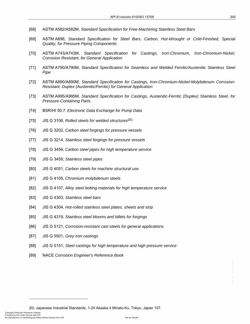
API STANDARD 610/ISO 13709 205
[68] ASTM A582/A582M, Standard Specification for Free-Machining Stainless Steel Bars
[69] ASTM A696, Standard Specification for Steel Bars, Carbon, Hot-Wrought or Cold-Finished, Special Quality, for Pressure Piping Components
[70] ASTM A743/A743M, Standard Specification for Castings, Iron-Chromium, Iron-Chromium-Nickel, Corrosion Resistant, for General Application
[71] ASTM A790/A790M, Standard Specification for Seamless and Welded Ferritic/Austenitic Stainless Steel Pipe
[72] ASTM A890/A890M, Standard Specification for Castings, Iron-Chromium-Nickel-Molybdenum Corrosion-Resistant, Duplex (Austenitic/Ferritic) for General Application
[73] ASTM A995/A995M, Standard Specification for Castings, Austenitic-Ferritic (Duplex) Stainless Steel, for Pressure-Containing Parts
[74] BSR/HI 50.7, Electronic Data Exchange for Pump Data
[75] JIS G 3106, Rolled steels for welded structures20)
[76] JIS G 3202, Carbon steel forgings for pressure vessels
[77] JIS G 3214, Stainless steel forgings for pressure vessels
[78] JIS G 3456, Carbon steel pipes for high temperature service
[79] JIS G 3459, Stainless steel pipes
[80] JIS G 4051, Carbon steels for machine structural use
[81] JIS G 4105, Chromium molybdenum steels
[82] JIS G 4107, Alloy steel bolting materials for high temperature service
[83] JIS G 4303, Stainless steel bars
[84] JIS G 4304, Hot-rolled stainless steel plates, sheets and strip
[85] JIS G 4319, Stainless steel blooms and billets for forgings
[86] JIS G 5121, Corrosion-resistant cast steels for general applications
[87] JIS G 5501, Grey iron castings
[88] JIS G 5151, Steel castings for high temperature and high pressure service
[89] NACE Corrosion Engineer's Reference Book
20) Japanese Industrial Standards, 1-24 Akaska 4 Minato-Ku, Tokyo, Japan 107. Copyright American Petroleum Institute Provided by IHS under license with API
Not for ResaleNo reproduction or networking permitted without license from IHS
--`,,```,,,,````-`-`,,`,,`,`,,`---

Copyright American Petroleum Institute Provided by IHS under license with API
Not for ResaleNo reproduction or networking permitted without license from IHS
--`,,```,,,,````-`-`,,`,,`,`,,`---
Invoice To (� Check here if same as “Ship To”)
Name:
Title:
Company:
Department:
Address:
City: State/Province:
Zip/Postal Code: Country:
Telephone:
Fax:
Email:
� Payment Enclosed � P.O. No. (Enclose Copy)
� Charge My IHS Account No.
� VISA � MasterCard � American Express� Diners Club � Discover
Credit Card No.:
Print Name (As It Appears on Card):
Expiration Date:
Signature:
Quantity Title Total
Subtotal
Applicable Sales Tax (see below)
Rush Shipping Fee (see below)
Shipping and Handling (see below)
Total (in U.S. Dollars)
� To be placed on Standing Order for future editions of thispublication, place a check mark in the SO column and sign here:
Date:
SO� Unit Price
� API Member (Check if Yes)
Ship To (UPS will not deliver to a P.O. Box)Name:
Title:
Company:
Department:
Address:
City: State/Province:
Zip/Postal Code: Country:
Telephone:
Fax:
Email:
Mail Orders – Payment by check or money order in U.S. dollars is required except for established accounts. State and local taxes, $10 processing fee, and 5% shipping must beadded. Send mail orders to: API Publications, IHS, 15 Inverness Way East, c/o Retail Sales, Englewood, CO 80112-5776, USA.Purchase Orders – Purchase orders are accepted from established accounts. Invoice will include actual freight cost, a $10 processing fee, plus state and local taxes.Telephone Orders – If ordering by telephone, a $10 processing fee and actual freight costs will be added to the order.Sales Tax – All U.S. purchases must include applicable state and local sales tax. Customers claiming tax-exempt status must provide IHS with a copy of their exemption certificate.Shipping (U.S. Orders) – Orders shipped within the U.S. are sent via traceable means. Most orders are shipped the same day. Subscription updates are sent by First-Class Mail.Other options, including next-day service, air service, and fax transmission are available at additional cost. Call 1-800-854-7179 for more information.
Shipping (International Orders) – Standard international shipping is by air express courier service. Subscription updates are sent by World Mail. Normal delivery is 3-4 days from shipping date.
Rush Shipping Fee – Next Day Delivery orders charge is $20 in addition to the carrier charges. Next Day Delivery orders must be placed by 2:00 p.m. MST to ensure overnight delivery.Returns – All returns must be pre-approved by calling the IHS Customer Service Department at 1-800-624-3974 for information and assistance. There may be a 15% restockingfee. Special order items, electronic documents, and age-dated materials are non-returnable.
Pricing and availability subject to change without notice.
2010 PUBLICATIONS ORDER FORM
Effective January 1, 2010. API Members receive a 30% discount where applicable. The member discount does not apply to purchases madefor the purpose of resale or for incorporation into commercial products, training courses, workshops, or other commercial enterprises.
Ordering Information Online: www.api.org/pubsPhone: 1-800-854-7179 (Toll-free in the U.S. and Canada) | (+1) 303-397-7956 (Local and International)Fax: (+1) 303-397-2740
Copyright American Petroleum Institute Provided by IHS under license with API
Not for ResaleNo reproduction or networking permitted without license from IHS
--`,,```,,,,````-`-`,,`,,`,`,,`---

THERE’S MOREWHERE THIS CAME FROM.
API Monogram® Licensing ProgramSales: (+1) 713-964-2662Service: (+1) 202-962-4791Fax: (+1) 202-682-8070Email: [email protected]: www.api.org/monogram
API Quality Registrar (APIQR®)• ISO 9001•ISO/TS 29001•ISO 14001•OHSAS 18001•API Spec Q1® •API QualityPlus®•Dual Registration Sales: (+1) 713-964-2662Service: (+1) 202-962-4791Fax: (+1) 202-682-8070Email: [email protected]: www.api.org/apiqr
API Individual Certification Programs (ICP®) Sales: (+1) 713-964-2662Service: (+1) 202-682-8064Fax: (+1) 202-682-8348Email: [email protected]: www.api.org/icp
API Engine Oil Licensing andCertification System (EOLCS)Sales: (+1) 713-964-2662Service: (+1) 202-682-8516Fax: (+1) 202-962-4739Email: [email protected]: www.api.org/eolcs
API Training Provider Certification Program (API TPCP™) Sales: (+1) 713-964-2662Service: (+1) 202-682-8075Fax: (+1) 202-682-8070Email: [email protected]: www.api.org/tpcp
API Perforator Design Registration ProgramSales: (+1) 713-964-2662Service: (+1) 202-682-8490Fax: (+1) 202-682-8070Email: [email protected]: www.api.org/perforators
API Credit Exchange (ACE™)Service: (+1) 202-682-8192Fax: (+1) 202-682-8070Email: [email protected]: www.api.org/ace
API Diesel Exhaust Fluid Certification Program Phone: (+1) 202-682-8516Fax: (+1) 202-962-4739Email: [email protected]: www.apidef.org
API WorkSafe™Sales: (+1) 713-964-2662 Service: (+1) 202-682-8469Fax: (+1) 202-682-8348Email: [email protected]: www.api.org/worksafe
API-UPhone: (+1) 202-682-8053Fax: (+1) 202-682-8070Email: [email protected]: www.api-u.org
API Data™Phone: (+1) 202-682-8499Fax: (+1) 202-962-4730Email: [email protected]: www.APIDataNow.org
API Publications Online: www.api.org/pubsPhone: 1-800-854-7179
(Toll-free: U.S./Canada)(+1) 303-397-7956 (Local/International)
Fax: (+1) 303-397-2740
API Standards Phone: (+1) 202-682-8148Fax: (+1) 202-962-4797Email: standards.orgWeb: www.api.org/standards
Request a Quotation:www.api.org/quote
Copyright American Petroleum Institute Provided by IHS under license with API
Not for ResaleNo reproduction or networking permitted without license from IHS
--`,,```,,,,````-`-`,,`,,`,`,,`---

Copyright American Petroleum Institute Provided by IHS under license with API
Not for ResaleNo reproduction or networking permitted without license from IHS
--`,,```,,,,````-`-`,,`,,`,`,,`---
Product No. CX61011
Copyright American Petroleum Institute Provided by IHS under license with API
Not for ResaleNo reproduction or networking permitted without license from IHS
--`,,```,,,,````-`-`,,`,,`,`,,`---