centurion systems (pty)ltd - introduction |...
TRANSCRIPT

D10 OPERATION MANUAL
Centurion Systems (Pty)Ltd

Centurion Systems (Pty)Ltd
i D10 OPERATION MANUAL
MENU 2: SAFETY ............................................................................................................................... 1
COLLISION FORCE................................................................................................................................ 1
COLLISION COUNT ............................................................................................................................... 1
ALARM OUTPUT ................................................................................................................................... 2
LCK AS ESTOP .................................................................................................................................... 2
MENU 4: MODES OF OPERATION ................................................................................................ 3
MENU 3: AUTOCLOSE ...................................................................................................................... 3
AUTOCLOSE OVERRIDE ........................................................................................................................ 3
MENU 5: RUN PROFILE ................................................................................................................... 4
PCM PUSH FORCE ............................................................................................................................... 4
PRE-OPEN DELAY ................................................................................................................................ 4
PRE-CLOSE DELAY............................................................................................................................... 5
OPENING SPEED .................................................................................................................................. 6
CLOSING SPEED ................................................................................................................................... 6
GATE SPEED ........................................................................................................................................ 6
RAMP-UP DISTANCE ............................................................................................................................ 7
RAMP-DOWN DISTANCE ....................................................................................................................... 7
TRG STOP DISTANCE ........................................................................................................................... 7
IRB STOP DISTANCE ............................................................................................................................ 8
CRAWL DISTANCE ................................................................................................................................ 8
GATE SPEED PROFILE .......................................................................................................................... 9
TORQUE LIMIT ................................................................................................................................... 10
MENU 6: IR BEAMS ......................................................................................................................... 12
PIRAC ............................................................................................................................................... 12
STOP ON OPEN ................................................................................................................................... 13
PIRAC OVERRIDE .............................................................................................................................. 13
INFRA-RED BEAM TEST ..................................................................................................................... 15
IRBO=IRBC ...................................................................................................................................... 16
BEAM ALARMS ................................................................................................................................... 16
MENU 7: PEDESTRIAN OPENING .............................................................................................. 17
PEDESTRIAN OPEN POSITION ............................................................................................................ 17
PEDESTRIAN AUTOCLOSE TIME ......................................................................................................... 18
PEDESTRIAN PRE-OPEN DELAY ......................................................................................................... 19
PEDESTRIAN PRE-CLOSE DELAY ....................................................................................................... 20
MENU 8: COURTESY LIGHT (PILLAR LIGHT) ....................................................................... 20
COURTESY LIGHT TIME ..................................................................................................................... 21
LIT FUNCTION ................................................................................................................................... 21
LIGHT PROFILE TABLE ...................................................................................................................... 22
MENU 9: CHRONOGUARD ............................................................................................................ 23
AUTO-ACTIVATION ............................................................................................................................. 25
TIME-BARRING .................................................................................................................................. 26
Time-barring Remote-controls ..................................................................................................... 27
Centurion Systems (Pty)Ltd
D10 OPERATION MANUAL ii
EXCLUSIONS ...................................................................................................................................... 28
MENU 10: GENERAL OPTIONS ................................................................................................... 29
OPERATING STANDARD ...................................................................................................................... 29
RESET OPTIONS ................................................................................................................................. 30
Factory Defaults............................................................................................................................ 31
Delete All Remotes ........................................................................................................................ 31
Delete All Time-periods ................................................................................................................ 31
Reset All ........................................................................................................................................ 31
DIAGNOSTIC SCREEN ......................................................................................................................... 31
ROUND TEST BUTTON ........................................................................................................................ 31
BACKUP AND RESTORE ONBOARD MEMORY ...................................................................................... 32
Backup EEPROM ......................................................................................................................... 32
Restore EEPROM ......................................................................................................................... 32
MENU 11: REMOTE CONTROLS .................................................................................................. 33
ID NUMBERS ...................................................................................................................................... 33
MULTIPLE-BUTTON COMBINATIONS .................................................................................................. 33
AUTOLEARN ....................................................................................................................................... 34
DELETE-NOT-PRESENT ..................................................................................................................... 35
REMOTE CONTROL MENU STRUCTURE .............................................................................................. 36
Add Remote ................................................................................................................................... 36
Delete Remote ................................................................................................................................ 36
Delete Remote by ID ...................................................................................................................... 36
Delete Remote Button ................................................................................................................... 37
Delete Remote by Button ............................................................................................................... 37
Delete-Not-Present ........................................................................................................................ 38
Delete All Remotes ........................................................................................................................ 38
Edit Remote Button ...................................................................................................................... 39
Autolearn ....................................................................................................................................... 39
Tx Menu Locked ............................................................................................................................ 40
Onboard Receiver .......................................................................................................................... 40
INFORMATION SCREENS............................................................................................................. 41
GENERAL INFORMATION .................................................................................................................... 42
DATE AND TIME INFORMATION .......................................................................................................... 48
BATTERY INFORMATION..................................................................................................................... 49
SPEED AND POSITION INFORMATION ................................................................................................. 50
CURRENT INFORMATION .................................................................................................................... 51
ENCODER INFORMATION .................................................................................................................... 53
MAGNET POSITION INFORMATION ..................................................................................................... 54
PWM AND PROFILE INFORMATION .................................................................................................... 55
OPERATING STATISTICS ..................................................................................................................... 56
PRODUCT INFORMATION .................................................................................................................... 58
DRIVE INTEGRITY INFORMATION ....................................................................................................... 59
REMOTE-CONTROL INFORMATION ..................................................................................................... 61
INPUT INFORMATION ......................................................................................................................... 63

Centurion Systems (Pty)Ltd
1 MENU 2: SAFETY D10 OPERATION MANUAL
MENU 2: SAFETY
COLLISION FORCE
There are two types of collisions that Centurion‟s controllers respond to:
1. Signature-based collisions (signature-collision)
2. Stall-based collisions (stall-collision)
Signature-collision detection and stall-collision detection are active whenever the „Collision Force‟
setting is set to anything other than maximum (in other words, settings one through five). If the
„Collision Force‟ is set to maximum (setting six), then the system will only respond to stall-
collisions. For more information on stall-collisions refer to the section in Menu 5 – Run Profile,
that deals with Torque Limit.
The system monitors the load profile of the gate, and when the magnitude and shape of the load
profile fit a particular “signature”, a collision is registered. This collision is called a signature-
collision.
The Collision Force setting determines the magnitude and shape the load profile must exhibit
before the system detects a signature-collision. This allows the user to tune to system to reject
general environmental disturbances (wind, poor rack and pinion mesh, rail joints, etc), but
register and respond to real obstructions (people, and property in the way of the gate). The
response following the detection of the collision will depend on the situation, but the gate will
typically retract to alleviate any force the gate may be exerting on the obstruction. For a
comprehensive table of collision responses, refer to section d, on page z.
The collision force can be adjusted independently in both the opening and closing directions.
Tuning the Collision Force setting, understanding that the system is generally looking for a
rapidly-changing load profile (a short, sharp jerk on the gate), will result in highly-sensitive and
reliable collision response characteristics.
COLLISION COUNT
If the number of collisions encountered exceeds the value set in the “Multiple Collision Counter”
setting, the controller will stop the gate wherever the final collision is encountered. Recovery
from a multiple collision condition depends on the operating profile that is currently active:
ZA and CE Profile - Any user-invoked gate action (TRG, FRX, PED) allows the system
to immediately recover from a multiple collision condition. The gate will behave according
to the invoked action.
Centurion Systems (Pty)Ltd
D10 OPERATION MANUAL 2
UL325 Profile - Either, the LCK input, that is implicitly configured to behave as an
Emergency Stop (NC – normally closed) input must be broken (interrupted), or the round
push-button on the controller must be pressed to clear the multiple collision condition.
The gate will neither move, nor allow any form of user invoked action to occur until the
multiple collision condition is cleared.
The status LED will flash four times to indicate that the system is in a multiple collision state.
Additionally, the allocated output (see Alarm output below) will activate while the condition is
active. If the allocated output is the buzzer (default alarm output setting), the buzzer will beep
(500ms on / 500ms off) continuously until the condition is cleared.
ALARM OUTPUT
If the multiple collision condition is active, an alarm output is driven. The output remains driven
while the multiple collision condition remains active (refer to the section on Collision Count to
determine how to clear the multiple collision state). The choice of output is determined by the
Alarm Output setting:
Buzzer – Onboard buzzer that beeps (500ms on / 500ms off) continuously.
Pillar/Courtesy Light Contact – potential-free, normally-open relay contact. The
circuit will switch 250VAC and 28VDC loads. The contact is fuse protected at 5A.
XIO – Open-drain, active-low (switched to ground) drive. Switches DC loads up to 3A.
The output is not fuse protected.
Safety-Beam Common - Open-drain, active-low (switched to ground) drive. Switches
DC loads up to 3A. The output is not fuse protected.
Status LED Output – Active-high, LED drive. Operates up to three LED‟s in parallel or
interfaces with a CP78 multi-LED driver card.
LCK AS ESTOP
Configures the physical Holiday Lockout (LCK) input to behave as an Emergency Stop input.
EStop is a normally-closed circuit. This prevents the gate from operating in the event that the
EStop circuit fails. In other words, it fails safe.
If EStop is triggered, the gate will immediately stop any currently running gate operation;
braking the gate on an aggressive stopping profile. While EStop remains active, all gate action is
inhibited.
Once the LCK input is configured to support EStop functionality, it no longer behaves as a
Holiday Lockout input. However, the user still has access to the Holiday Lockout function via a
remote learnt to Holiday Lockout on the onboard receiver. This allows for both functions to be
supported simultaneously in applications that require it.

Centurion Systems (Pty)Ltd
D10 OPERATION MANUAL 3
MENU 4: MODES OF OPERATION
Don‟t know if I should document modes of operation? It‟s a difficult section to document correctly.
MENU 3: AUTOCLOSE
AUTOCLOSE OVERRIDE
It is possible to disable Autoclose for a single operation. Autoclose can only be overridden if:
1. The feature is enabled (Autoclose set to on)
2. The gate is operating in Standard or Reversing mode.
To override Autoclose, follow the steps below paying attention to the behaviour of the gate in
each of the modes of operation:
STANDARD MODE
The gate must be stationary, and in a state where the next TRG-based user-
operation will cause the gate to open. Additionally, the time to reach the fully open
position must exceed the Autoclose-override time.
Activate and hold the TRG input for a time equal to, or exceeding, the time specified by
the Autoclose-override setting.
The gate will begin to open, and stop when the Autoclose-override time is reached.1
The gate will remain stopped while the TRG input is held activated, and PIRAC is
disabled (Refer to PIRAC override, page z, for more information).
At this stage the Autoclose feature has been overridden. The gate will continue to open to
the fully open limit when the TRG input is released.
The system will remain in this autoclose-override state until the gate reaches its fully
closed position. This means the gate can be stopped repeatedly anywhere throughout its
travel, and not close automatically; but only while it hasn‟t reached its fully closed
position.
REVERSING MODE
The gate must be stationary, or closing, and in a state where the next TRG-based
user-operation will cause the gate to open. Additionally, the time to reach the fully
open position must exceed the Autoclose-override time.
Activate and hold the TRG input for a time equal to, or exceeding, the time specified by
the Autoclose-override setting.
The gate will begin to open, and stop when the Autoclose-override time is reached.1
The gate will remain stopped while the TRG input is held activated, and PIRAC is
disabled (Refer to PIRAC override, page z, for more information).
At this stage the Autoclose feature has been overridden. The gate will continue to open to
the fully open limit when the TRG input is released.
The system will remain in this autoclose-override state until the gate reaches its fully
closed position. This means the gate can be stopped repeatedly at the open position2, and
not close automatically; but only while it hasn‟t reached its fully closed position.
1 If the gate reaches its fully open position before the Autoclose-override time is reached, the

Centurion Systems (Pty)Ltd
D10 OPERATION MANUAL 4
In both modes of operation, any input that causes the gate to alter the opening operation while
Autoclose is being overridden (while TRG is held and the gate is opening) will cause the system
to ignore the Autoclose-override request.
MENU 5: RUN PROFILE
PCM PUSH FORCE
Modifying this value adjusts the push-force of the gate during the Positive Close Mode phase of
operation. This is useful in cases where the gate, or supporting post (or other end-stop) is not
rigid enough; they may twist or buckle as the operator drives the gate into its end-stop. The PCM
force is set as a percentage of the maximum push-force of the system (refer to the section on
„Torque Limit‟ to determine how to set the maximum push-force of the gate.)
PRE-OPEN DELAY
Provides a delay between a user-based, opening, gate-activation, and the commencement of
gate movement in the opening direction. The delay is configurable in one second increments from
zero seconds to 65 seconds (one minute and five seconds).
The rules for invocation of the Pre-open delay are generalised below:
1. Any user-based opening command that will result in the gate altering its state,
to move in the opening direction will invoke a pre-open delay prior to the
opening movement.
2. During the autoclose-override operation, after the gate comes to an initial stop,
a pre-open delay is invoked after the TRG input is released and before the gate
starts moving again.
3. During the PIRAC-override operation, after the gate comes to an initial stop
indicating that PIRAC has been successfully overridden and before the gate
starts moving again, a pre-open delay is invoked.
Notes on the rules:
o Rule 1 holds for all the modes of operation, the specifics of which are documented
below:
In the Standard, Reversing and Condominium modes of operation,
opening commands may only originate from the TRG and FRX inputs.
In the PLC mode of operation, opening commands may only originate from
the FRX input.
In the Deadman mode of operation, opening commands may only originate
when the FRX input is held active.
o Rules 2 and 3 only pertain to Standard, Reversing and Condominium modes of
operation.
2 Since the gate is in Reversing mode it is not possible short of causing, an opening collision, a
closing collision (in UL325 profile), a series of collisions, breaking an opening safety beam, or
breaking a combination of safety beams, to stop the gate at any point except the open or closed
limit.

Centurion Systems (Pty)Ltd
D10 OPERATION MANUAL 5
o An opening command that is generated by a safety beam input (SAF OPEN or
SAF CLOSE) is not considered to be a user-based command. This pertains even
if the PIRAC feature is enabled.
o Rule 1 holds true irrespective of whether the gate is stationary or closing.
o In rule 1, a closing gate will be commanded to stop before the pre-open delay is
executed.
o In rule 1, if an opening command commands the gate to open, while the gate is
opening, the system does not need to alter its state to service the command (since it
is already opening) and therefore will not invoke a pre-open delay.
o One may assume that any opening movement that is not handled by the rule is not
preceded by a pre-open delay.
PRE-CLOSE DELAY
Provides a delay between a closing gate-activation signal being received, and the
commencement of gate movement in the closing direction. The delay is configurable in one second
increments from zero seconds to 65 seconds (one minute and five seconds).
The rules for invocation of the Pre-Close delay are documented below:
1. Any user-based closing command (excluding PED when the gate is partly-open
or partly-closed) that will result in the gate altering its state to move in the
closing direction, will invoke a pre-close delay prior to the closing movement
2. A system-based closing command (i.e. Autoclose), from any gate position, will
invoke a pre-close delay after the autoclose-time expires and prior to the
closing movement commencing.
3. If the PIRAC feature is enabled, a pre-close delay is invoked when the closing
beam (SAF CLOSE) is cleared, and prior to the closing movement commencing.
This occurs irrespective of whether the ‘Stop on Open’ feature is enabled or
not.
4. If the gate is fully open, and no autoclose operation will take place (Autoclose is
disabled, disabled from fully open, or overridden), and a PED input is received,
a pre-close delay will occur prior to the gate closing.
Notes on the rules:
o Rule 1. holds for all the modes of operation, the specifics of which are documented
below:
In Standard and Reversing mode, closing commands may only originate
from the TRG input (see rule 4 for special case regarding PED).
In Condominium mode, there is no user-based closing command.
In the PLC mode, closing commands may only originate from the TRG
input.
In the Deadman mode, closing commands may only originate when the
TRG input is held active.
o Rules 2, 3 and 4 only apply when the system is operating in Standard, Reversing,
or Condominium modes of operation. Some or all of the features cannot be enabled
in the other two modes.
o Rule 1 and 3 hold true irrespective of whether the gate is stationary or opening.
o An opening gate will be commanded to stop before the pre-close delay is executed.

Centurion Systems (Pty)Ltd
D10 OPERATION MANUAL 6
o In rule 1, if a closing command, commands the gate to close, while the gate is
closing, the system does not need to alter its state to service the command (since it
is already closing) and therefore will not invoke a pre-close delay.
o One may assume that any closing movement that is not handled by any of the
above rules is not preceded by a pre-close delay.
OPENING SPEED
Sets the opening speed of the gate in units of metres per minute (m/min). The speed is
configurable from 10m/min to 24m/min in 1m/min increments. It is possible, depending on the
operating standard, to specify that the gate must open as fast as possible by setting the „Opening
Speed‟ value to „MAX‟. Refer to the table under the general section, Gate Speed, detailing the
possible speed settings for each profile.
CLOSING SPEED
Sets the closing speed of the gate in units of metres per minute (m/min). The speed is
configurable from 10m/min to 24m/min in 1m/min increments. It is possible, depending on the
operating standard, to specify that the gate must close as fast as possible by setting the „Closing
Speed‟ value to „MAX‟. Refer to the table under the general section, Gate Speed, for a list of speed
settings for each profile.
GATE SPEED
If the speed is explicitly set to some value other than „MAX‟, then the system is said to be
operating in a closed-loop configuration. This means that the controller will attempt to
dynamically control the running speed of the gate to match the explicitly set speed.
For example:
If the gate is running too slowly, the controller will increase the speed of the motor until
the gate is operating at the correct speed.
Similarly, if the gate is running too fast, the controller will decrease the speed of the
motor (exactly analogous to applying a brake to the gate) until the gate is operating at
the correct speed.
It will do this constantly over the full running travel of the gate. Thus it no longer matters
whether the gate is running on an inclined or uneven plane – the speed is always consistent
Closed-Loop Speed MAX
Option
Default
Speed Minimum Maximum
ZA Profile 10 m/min 24 m/min ● Max
CE Profile 10 m/min 24 m/min ○ 24 m/min
UL325 Profile 10 m/min 24 m/min ○ 24 m/min

Centurion Systems (Pty)Ltd
D10 OPERATION MANUAL 7
(uphill or downhill). In other words, the controller compensates for running irregularities
ensuring that the speed is always maintained at the desired value3.
On the other hand, if the speed is set to „MAX‟, the system is running in an open-loop
configuration, and will always attempt to run the gate as fast as possible. The ramp-up and
ramp-down phases of gate travel are fully controlled, but when the gate reaches the running
phase, the motor is run at its maximum RPM (or maximum achievable RPM for heavy loads).
Thereby maximising the running speed of the gate.
RAMP-UP DISTANCE
Sets the distance over which the gate accelerates from standstill to either, the „Opening Speed‟,
or „Closing Speed‟; depending on whether the gate is opening or closing respectively. The distance
can be set from 0.1m to 9.99m in 10mm increments. Refer to the section, Gate Speed Profile, for
details on how the „Ramp-up Distance‟ parameter is used to build a gate speed profile.
RAMP-DOWN DISTANCE
Sets the distance over which the gate decelerates from the currently set „Opening Speed‟ or
„Closing Speed‟, to the crawl speed. The crawl speed is a fixed speed of approximately 4.5m/min.
The distance can be set from 0.1m to 9.99m in 10mm increments. Refer to the section, „Gate
Speed Profile‟, for details on how the „Ramp-down Distance‟ parameter is used to build a gate
speed profile.
TRG STOP DISTANCE
Sets the distance over which a gate will decelerate from the currently set „Opening Speed‟ or
„Closing Speed‟, to a complete stop. This distance parameter is used when any user-based, gate-
activation input commands the gate to stop4. Examples of such inputs include TRG (to stop
gate), FRX (on gate reversal from close to open), PED (on gate reversal during a pedestrian
cycle), etc. As the examples illustrate, a command to stop the gate may form part of a larger gate
reversal profile (from close to open, or in rare cases, from open to close).
Bear in mind that the distance is based on the gate decelerating from the „Opening Speed‟ or
„Closing Speed‟ to a complete stop. Should the current speed be less than the opening or closing
speed respectively, then the distance is scaled to keep the same deceleration profile. In other
words, the system will reduce the distance over which it decelerates if the speed at which a
stopping command is received is less than the currently set running phase speed. Refer to figure
y, graph A, for a depiction of the fixed deceleration profile.
The distance can be set from 0.1m to 1.0m in 10mm increments. In certain applications it may be
useful to set large stopping distance (approaching 1m) – this will ensure smooth stopping and
reduce the load on mechanical components as the system decelerates. In such cases, there is a
3 It is important to understand that a finite amount of mechanical power can be delivered by the
system. If the gate requires more power than is available, then the controller will not be able to
achieve the set-point speed. For good speed control, ensure that the pull-force specifications for
the operator are not exceeded.
4 Safety beam inputs (SAF Open and SAF Close) are considered safety-based, gate-activation
inputs, and hence do not use the „TRG Stop Distance‟ when they command the gate to stop.

Centurion Systems (Pty)Ltd
D10 OPERATION MANUAL 8
significant delay from when the gate is triggered to stop to when it finally comes to rest. This
may be a problem from an obstacle avoidance point of view. To overcome this, the system allows
a second trigger signal to shorten the stopping profile. The first trigger will stop the gate on the
„TRG Stop Distance‟ profile. If a second trigger is received while the gate is slowing down, the
system will transition to a steeper stopping profile (an emergency stopping profile). Refer to
figure y, graph B.
IRB STOP DISTANCE
Sets the distance over which a gate will decelerate from the currently set „Opening Speed‟ or
„Closing Speed‟, to a complete stop. This distance parameter is used when any safety-based,
gate-activation input commands the gate to stop. A command to stop the gate that originates
with the safety inputs may form part of a larger gate reversal profile (from close to open).
Bear in mind that the distance is based on the gate decelerating from the „Opening Speed‟ or
„Closing Speed‟ to a complete stop. Should the current speed be less than the opening or closing
speed respectively, then the distance is scaled to keep the same deceleration profile. In other
words, the system will reduce the distance over which it decelerates if the speed at which a
stopping command is received is less than the currently set running phase speed. Refer to figure
y, graph A, for a depiction of the fixed deceleration profile.
The distance can be set from 0.1m to 1.0m in 10mm increments
CRAWL DISTANCE
Sets the distance that the gate crawls before it finally comes to rest. The crawl is fixed at
approximately 4.5m/min. The crawl distance should be adjusted so that the gate slows down in a
controlled manner, and gently and quietly stops at its end-points. The distance can be set from
0.03m to 9.99m in 10mm increments. Refer to the section, Gate Speed Profile, for details on how
the „Crawl Distance‟ parameter is used to build a gate speed profile.

Centurion Systems (Pty)Ltd
D10 OPERATION MANUAL 9
GATE SPEED PROFILE
The controller configures a speed profile prior to every operation. The profile dictates how the
gate must move to get from its starting point to its final point of rest. Typically, speed profiles
consist of four distinct phases:
1. Ramp-up phase – The gate accelerates from rest to the required „Opening Speed‟ or
„Closing Speed‟ setting.
2. Run phase – The gate runs at the desired „Opening Speed‟ or „Closing Speed‟ setting.
3. Ramp-down phase – The gate decelerates from the opening or closing speed configured
during the run phase, down to the crawl speed.
4. Crawl phase – The gate runs at the crawl speed (approximately 4.5 m/min) for the
distance set by the „Crawl Distance‟ parameter and then comes to rest.
Although most installations will run all four phases during a typical opening or closing cycle, it is
possible to have fewer phases run. No recommendations are provided on the ideal distances for
each of the distance parameters (Ramp-up, Ramp-down, and Crawl). They are not even limited
by the opening distance of the gate. The user may specify any distance within the maximum
limits set for that distance parameter.
However, the system will always build a profile that does not invalidate the physical limits of
travel and will ensure that the profile is always smooth. So, even though it is possible to set large
distance parameters, the system will limit the distances to reasonable values. The profile is built
in reverse in the following manner:
The crawl phase is always satisfied first. If the crawl phase is longer than the distance
the gate must travel over, then the crawl phase is the only phase that the system will
run. See figure x, graph A.
Next the system looks at whether the ramp-up and ramp-down profiles intersect. If they
do, then the system configures a profile that ramps-up, intersects with the ramp-down
profile, and ramps-down. No run phase is built in this configuration. See figure x, graph
B and C.
Finally, if the ramp-up and ramp-down profiles do no intersect, the system configures the
full four-phase profile. Ramp-up, run, ramp-down, and finally crawl. See figure x, graph
D.
The conclusion that should be drawn is that although the system will always function correctly,
the installer, or end-user, should tune the distance parameters so that the speed-profile always
suits the installation.

Centurion Systems (Pty)Ltd
D10 OPERATION MANUAL 10
TORQUE LIMIT
„Torque Limit‟ is a representation of the maximum mechanical force that the motor will deliver.
This is not to say that the motor will guarantee to deliver this force, only that it will not deliver
more than this force5. The setting is dimensionless (in other words it does not have formal units),
and can be set from 4 to 10 in increments of 1. A value of 4 means that the minimum amount of
force will be delivered by the motor. By logical extension, a value of 10 means that a maximum
amount of force will be delivered by the motor.
„Torque Limit‟ comes into play in two situations:
1. Heavy and/or poorly running gates – If the gate is heavy or runs poorly, then limiting
the mechanical force that the motor delivers can have an impact on the running
characteristics of the gate. The gate may appear slow to respond taking a long time to
accelerate or decelerate. This is simply because the controller is limiting the force that
the motor is allowed to deliver to the gate. Increasing the „Torque Limit‟ will typically
address this problem; so long as the gate meets the weight and push-force specifications
(Refer to product specifications, page c for further information).
2. Stall collisions – The „Torque Limit‟ setting is most acutely felt when the gate reaches
its stall point (i.e. where the gate‟s speed drops to zero). This is because the maximum
push-force of the motor is delivered at, or very close to, stall. Therefore, by reducing the
‟Torque Limit‟ setting, it is possible to limit the push-force delivered by the gate when it
pushes up against an immovable and rigid object. It is advisable to tune the „Torque
Limit‟ setting to deliver just enough force to run the gate correctly; while minimising the
force exerted by the gate in the event of a collision.
5 The torque-speed characteristic of DC motors is such that the maximum torque (and in turn the
maximum motor force) is delivered when the rotor is locked (in other words when the motor is
not turning – zero speed). At all other points over the speed-range of the motor, the torque is not
at a maximum.

Centurion Systems (Pty)Ltd
D10 OPERATION MANUAL 11
The second point warrants a short discussion on stall-based collisions (stall-collisions). Centurion
controllers have a final6 failsafe mechanism to prevent people and/or property from being crushed
by the gate. This mechanism is the detection of a collision when the gate stalls. If the motor stalls
(stops rotating) for a short period of time (approximately 300ms), because it is pushing up
against an immovable and rigid object, the controller will immediately detect a stall-collision.
The response following the detection of the collision will depend on the situation; typically, the
gate will retract to alleviate any compressive force the gate may be exerting on the obstruction.
For a comprehensive table of collision responses, refer to section d, on page z.
6 The first and best option to ensure safe operation is to install safety devices (safety beams,
sensitive edges, etc). Following this the controller has a built in signature-collision detection
mechanism. If configured correctly, this is an effective mechanism to ensure safe operation.
However the user can disable signature-collision detection, or in rare cases, the controller may
not detect the signature of the collision correctly. Refer to the section dealing with „Collision
Force‟ for a more thorough explanation of signature-collisions.

Centurion Systems (Pty)Ltd
D10 OPERATION MANUAL 12
MENU 6: IR BEAMS
PIRAC
The Passive Infra-Red AutoClose (PIRAC) feature allows the gate to close automatically and
immediately after a pedestrian or vehicle has broken, and subsequently cleared the closing beam.
This security feature ensures that the gate stays open for the minimum amount of time possible.
The following list of rules comprehensively describes the behavior of the PIRAC feature:
If the closing beam is broken, and remains broken, while the gate is:
Opening:
o And, if ‘Stop on Open’ is:
Disabled - The system will not alter its state in any way, continuing to open until it
reaches the open limit7. Refer to the rule below for a fully-open gate for further
behavior.
Enabled - The gate will open past the point where the closing beam was initially
broken plus the Stop on Open „Stopping Distance‟ plus the „IRB Stop Distance‟ as the
gate slows down. (eg. If the closing beam was broken at point x, then the final stopping
position, xF = x + StopOnOpenDist + IRBStopDistance [towards open limit]). The
system may reach the open-limit before reaching the intended stop point. If this is the
case, the gate will transition to the fully-open state; otherwise it will transition to the
partly-open state. Refer to the correct state rules below (fully-open, or partly-open gate)
for further behavior.
Closing:
o The system will issue an infra-red beam stop command (stopping over the „IRB Stop
Distance‟ setting). If ‘Stop on Open’ is:
Disabled - The gate will reverse and open until it reaches the fully-open limit7. Refer to
the rule below for a fully-open gate for further behaviour.
Enabled - And, if the Stop on Open „Stopping Distance‟ is set to:
Zero distance - The gate will simply stop after the beam stop command. (eg. If the
closing beam was broken at point x, then the final stopping point, xF = x –
IRBStopDistance [towards closed limit]). The system transitions to a partly open-
state at this stage, so refer to the rule for a partly-open gate for further behavior.
Non-zero distance - Following the beam stop command the gate will open past the
point where the closing beam was initially broken plus the Stop on Open „Stopping
Distance‟ plus another „IRB Stop Distance‟ as the gate slows down again. (eg. If the
closing beam was broken at point x, then the final stopping position, xF = x +
StopOnOpenDist + IRBStopDistance [towards open limit]). The system may
reach the open-limit before reaching the intended stop point. If this is the case, the
gate will transition to the fully-open state; otherwise it will transition to the partly-
open state. Refer to the correct state rules below (fully-open, or partly-open gate) for
further behavior.
Fully-open:
o The system will inhibit any further gate action, holding the gate in the current position.
7 Unless, of course, it encounters a collision in which case it will stop. No retraction will take
place, even if a retraction-response should have taken place. This is because the closing safety
beam is broken preventing any form of closing operation.

Centurion Systems (Pty)Ltd
D10 OPERATION MANUAL 13
o The system will clear any currently running autoclose timer, preventing the gate from
auto-closing. (This applies if Autoclose is enabled and active from the current position).
Partly-open or Partly-closed:
o The system will inhibit any further closing gate action. If a valid opening gate-activation
input is received, and the opening safety beam input is not preventing the operation, the
gate will proceed to the fully-open limit7. Refer to the rule for a fully-open gate for further
behavior.
o The system will clear any currently running autoclose timer, preventing the gate from
auto-closing. (This applies if Autoclose is enabled and active from the current position).
Resolving its position (Due to a collision):
o The system will not handle the PIRAC operation correctly, treating the broken closing
safety beam input, as a standard safety input. The PIRAC behavior will function again
once the gate has finished resolving its position (i.e. when it stops moving).
If the closing beam is subsequently cleared, and the gate is in one of the following states:
Opening:
o The system will issue a standard stop command (stopping over the „TRG Stop Distance‟
setting), following which the gate will reverse direction and begin to close.
Closing:
o The system will ramp back up to full-speed (because it will be slowing down)8 and continue
to close.
Fully Open, Partly-open, or Partly-closed:
o The gate will close.
STOP ON OPEN
If PIRAC is enabled, and a vehicle breaks the closing safety beam, the gate will, by default,
continue to open. If the gate is required to stop at this point, the „Stop on Open‟ function must be
enabled. The „Stopping Distance‟ that is associated with the „Stop on Open‟ feature determines
the distance that the gate must continue to open after the closing beam is initially broken. The
„Stopping Distance‟ can be set from 0.00m to 9.99m in 10mm increments.
PIRAC OVERRIDE
It is possible to disable the PIRAC feature for a single operation. This prevents the closing beam
from triggering the gate to close. It‟s useful in cases where the user wishes to open their gate and
leave it in the open position; irrespective of the traffic that passes in and out of the gate. PIRAC
can only be overridden if:
1. The feature is enabled
2. The gate is operating in Standard or Reversing modes9.
8 It‟s rare that the system will be in this state when the closing beam is cleared. It occurs when
the gate is still slowing down on an IRB stopping profile in a closing direction, because the
closing beam was broken.
9 It is not possible to override Autoclose or PIRAC in Condominium mode because the user would
have no mechanism to close the gate. The PIRAC feature cannot be enabled in PLC and
Deadman modes of operation, and therefore cannot be overridden.

Centurion Systems (Pty)Ltd
D10 OPERATION MANUAL 14
To override PIRAC, follow the steps below paying attention to the behaviour of the gate in each of
the modes of operation:
STANDARD MODE
The gate must be stationary, and in a state where the next TRG-based user-operation
will cause the gate to open. Additionally, the time to reach the fully open position must
exceed the length of time that the TRG input must be active before the gate stops
initially. Refer to the point below for the time period.
Activate and hold the TRG input for a time equal to, or exceeding, the greater of either:
o The Autoclose-override time, if Autoclose is enabled, and the Autoclose-override time
is not set to off, or,
o Two-seconds, which is the PIRAC override time if Autoclose is disabled, and/or the
Autoclose-override time is set to off.
The gate will begin to open, and stop when the time period detailed above is reached.10
Continue to hold the TRG input. After three seconds the gate will begin to open to the
open limit again.
At this stage the PIRAC feature has been overridden, and the TRG input can be released.
The gate will continue to open to the fully open limit, and the closing safety beam will not
cause the gate to close when/if the beam is cleared.
The system will remain in this PIRAC-override state until the gate reaches its fully-
closed position. This means the gate can be stopped repeatedly anywhere throughout its
travel, and not close automatically when the safety beam is cleared; but only while it
hasn‟t reached its fully closed position.
REVERSING MODE
The gate must be stationary, or closing, and in a state where the next TRG-based user-
operation will cause the gate to open. Additionally, the time to reach the fully open
position must exceed the length of time that the TRG input must be active before the
gate stops initially. Refer to the point below for the time period.
Activate and hold the TRG input for a time equal to, or exceeding, the greater of either:
o The Autoclose-override time, if Autoclose is enabled, and the Autoclose-override time
is not set to off, or,
o Two-seconds, which is the PIRAC override time if Autoclose is disabled, and/or the
Autoclose-override time is set to off.
The gate will begin to open, and stop when the time period detailed above is reached10.
Continue to hold the TRG input. After three seconds the gate will begin to open to the
open limit again.
At this stage the PIRAC feature has been overridden, and the TRG input can be released.
The gate will continue to open to the fully open limit, and the closing safety beam will not
cause the gate to close when/if the beam is cleared.
The system will remain in this PIRAC-override state until the gate reaches its fully-
closed position. This means the gate can be stopped repeatedly at the open position11, and
10 If the gate reaches its fully open position before the time period is reached, the override request
will be ignored. In such cases, PIRAC is still active, and the gate will close if the closing beam is
cleared after being broken.
11 Since the gate is in Reversing mode it is not possible short of causing, an opening collision, a
closing collision (in UL325 profile), a series of collisions, breaking an opening safety beam, or

Centurion Systems (Pty)Ltd
D10 OPERATION MANUAL 15
not close automatically when the safety beam is cleared; but only while it hasn‟t reached
its fully closed position.
In both modes of operation, any input that causes the gate to alter the opening operation while
PIRAC is being overridden (while TRG is held and the gate is opening or stopped) will cause the
system to ignore the PIRAC-override request.
INFRA-RED BEAM TEST
Automatically tests the safety beams before a gate operation to verify that the devices are
working as intended. It is possible for the safety beams to fail in an unsafe state in certain
situations; this could result in the gate causing damage to people, and/or property. Enabling the
safety beam test will ensure that the beams are working correctly before the gate begins to move.
For the beam test to work, the negative terminal of the infra-red transmitter must be wired into
the SAF COM terminal on the controller. Refer to the wiring diagram on page w for more
information.
The user has full control over which beams are tested. In the „IR Beam Test‟ menu under the
„Test Beam‟ item, the user can configure the system to test the:
Closing beam (IRBC) only
Opening beam (IRBO) only
Both (IRBC and IRBO) beams
Beams are tested after a valid gate activation input is triggered (TRG, FRX, PED, Autoclose).
They are not tested, during any form of collision response action, during a beam response action,
or during an emergency stop operation.
The closing beam is only tested from the following positions:
Fully-open position
Pedestrian open position
The opening beam is only tested from the following positions:
Fully-closed position
At all other points, whether the gate is stationary or moving, a beam test operation is not
performed.
If a beam-test passes, the gate proceeds as per normal, with the user completely oblivious to any
beam-test operation taking place. If, on the other hand, a beam-test fails, the gate will not move
from the fully-open, fully-closed, or pedestrian-open limits. The user is notified of the failure with
an onscreen message and an alarm tone that is emitted from the onboard buzzer12.
breaking a combination of safety beams, to stop the gate at any point except the open or closed
limit.
12 The tone sounds once per second for a period of three seconds.

Centurion Systems (Pty)Ltd
D10 OPERATION MANUAL 16
IRBO=IRBC
Configures the opening safety beam input to logically behave as both an opening and closing
safety beam input. This means that if the beam connected to the opening beam input is broken,
the controller recognises the signal as if both the opening and closing beams are broken.
The logical duality that the opening beam inherits when IRBO=IRBC is enabled, is maintained
consistently across all the controller functions associated with beams. This includes safety beam
tests, and beam alarm functionality. In other words, if there is a function associated with the
closing beam input, and IRBO=IRBC is enabled, then that same function is also verified on the
opening beam input.
BEAM ALARMS
There are two distinct beam alarms that can be activated:
Ambush Alarm - This alarm is activated when the opening or closing beam inputs are
interrupted for an extended period of time. The ambush alarm works irrespective of the position
of the gate. The alarm is useful where a would be hijacker/attacker covers either the opening or
closing set of beams to prevent the gates from either opening or closing respectively.
The period of time which the beam/beams must remain interrupted before the alarm is triggered,
is configurable under the „Broken IRB Time‟. It can be set from one minute to four hours, in one
minute increments.
Once the alarm is triggered it remains active while the beam remains interrupted. The alarm is
cleared as soon as the beam is cleared.
Break-In Alarm - This alarm is activated if the closing safety beam (that is typically positioned
on the outside of the property) is interrupted when the gate is in its fully-closed position. If the
gate is moving, or stationary in a fully or partly open position, the closing beam is not monitored
for the alarm condition. This includes the situation where the gate is manually disengaged and
moved past the origin magnet.
The closing beam must be interrupted for a minimum of 100ms before the system registers an
alarm condition. This feature is built in to reduce false triggering in the event of insects and
other animals (birds, bats) from interrupting the beam for short periods of time. In addition to
this though, it is recommended that two parallel closing beams are fitted to prevent other cases
of false triggering.
Once the alarm is triggered it remains active for a period of 30s. The time period is fixed,
although the alarm condition can be cleared earlier than this by pressing the ellipse button on
the control card. The alarm can be retriggered indefinitely, irrespective of whether the previous
alarm state is cleared on not. If the alarm is retriggered within the 30s period that it is active,
the timer counting the 30s period simply starts counting again.
Both IRB alarms activate a single configurable output. The output is set in the „Alarm Output‟
menu under „IR Beam Alarms‟. It can be configured to be any one of the following outputs:
Buzzer - Onboard buzzer that beeps (500ms on/500ms off) while the alarm state is valid.
Pillar/Courtesy Light Contact - potential-free, normally-open relay contact. The
circuit will switch 250VAC and 28VDC loads. The contact is fuse protected at 5A.
Centurion Systems (Pty)Ltd
D10 OPERATION MANUAL 17
XIO - Open-drain, active-low (switched to common) drive. Switches DC loads up to 3A.
The output is not fuse protected.
Safety-Beam Common - Open-drain, active-low (switched to common) drive. Switches
DC loads up to 3A. The output is not fuse protected.
Status LED Output - Active-high, LED drive. Operates up to three LED‟s in parallel or
interfaces with a CP78 multi-LED driver card.
MENU 7: PEDESTRIAN OPENING
The pedestrian feature opens the gate a short distance to allow pedestrian access through the
gate. Activating the PED input on the control card invokes this feature. Installing a simple key-
switch, keypad, or equivalent access control device and wiring the output back to the PED input
on the controller makes for a simple, yet effective, electronically controlled pedestrian entrance.
The typical, and default, sequence of events that occur when the PED input is triggered is
documented below:
The controller begins timing a Pedestrian Pre-open delay. The delay time is configurable.
If a courtesy light is installed, it will flash during the pre-open period13. In situations
where a key-switch is installed inside the property (and the pedestrian is outside), this
delay allows the pedestrian to release the key-switch before the gate begins moving. If
pedestrian is triggered from a remote control, this delay is probably not required.
After the Pre-open delay time has elapsed, the gate opens to the pedestrian limit. The
opening limit is configurable.
The gate remains at the pedestrian limit for the Pedestrian-Autoclose time and
Pedestrian Pre-close delay time. Both time periods are configurable. It is worth noting
that the Pedestrian-Autoclose cannot be disabled. In other words, short of holding the
PED input active permanently, there is no way to keep the gate open at the pedestrian
limit indefinitely.
Following the Pedestrian-Autoclose time delay, the system begins timing the Pedestrian
Pre-close delay. If a courtesy light is installed, it will flash during the pre-close period13.
After the Pre-close delay time has elapsed, the gate closes to the closed limit.
Depending on the position of the gate, the state of the inputs, and the parameters associated with
pedestrian, it is possible to skip certain of the steps outlined above. Refer to the configuration
parameters below for more information.
PEDESTRIAN OPEN POSITION
Sets the pedestrian open-limit. The limit can be adjusted from 50mm to the fully-open limit of
the gate, in 10mm increments. The factory-default fully-open limit is set to 50m, and hence the
pedestrian limit can be set from 50mm to 50m initially. The factory-default pedestrian limit for
all three operating profiles14 is 1m.
13 The courtesy light will flash if the light profile is configured as the Courtesy Light Profile, or
Pre-Flash B Profile. In the Pre-Flash C Profile, the courtesy light will activate, but not flash
(useful for rotating beacon lights). In the Pre-Flash A Profile, the courtesy light does not activate
at all during the pre-open and pre-close delay.
14 ZA, CE, UL325
Centurion Systems (Pty)Ltd
D10 OPERATION MANUAL 18
At the end of a gate setup procedure, the currently programmed pedestrian limit is verified to
make sure that it falls within the bounds of standard gate travel. Additionally, the limit is
verified to make sure that during a pedestrian opening that the origin magnet on the gate passes
the origin sensor on the operator.
The procedure to verify the pedestrian limit is documented below:
If the PL is greater than the OL, then the PL is set to the OL – 20mm.
Otherwise, if the PL is less than the MP, and the OL is greater than the MP by 100mm or
more, then the PL is set to the MP + 100mm.
Otherwise, if the PL is less than the MP, and the OL is greater than the MP by less than
100mm, then the PL is set to the MP.
Otherwise, the PL is not adjusted as it falls somewhere between the OL and the MP.
Where:
PL – Current pedestrian limit
OL – Fully-open gate limit
MP – Magnet position (Distance from magnet to operator when the gate is fully closed)
Remember that this procedure is only run once after setup. This means that although the
pedestrian limit will be adjusted correctly after setup, there is nothing that prevents the user
from adjusting the limit after setup to suit any requirement he/she may have; even if that
requirement may invalidate some of the above rules.
PEDESTRIAN AUTOCLOSE TIME
This is the time period in seconds that the gate will remain open (excluding the pre-close delay)
during a pedestrian cycle15. The time can be set from 0 seconds to 4 minutes in 1 second
intervals. Take note that the pedestrian autoclose may not be disabled. In other words, short of
holding the PED input active permanently, there is no way to keep the gate open at the
pedestrian limit indefinitely.
15 A pedestrian cycle is flagged when a pedestrian command (PED) is initially acted upon,
and is cleared when the gate reaches its fully-closed limit, or another user-based, gate-
activation input (eg. FRX) is received.

Centurion Systems (Pty)Ltd
D10 OPERATION MANUAL 19
PEDESTRIAN PRE-OPEN DELAY
Provides a delay between a pedestrian gate-activation input, and the commencement of gate
movement in the opening direction. The delay is configurable in one second increments from zero
seconds to 65 seconds (one minute and five seconds) [must be confirmed].
The rules for invocation of the Pedestrian Pre-Open delay are documented below:
1. A pedestrian command that is received while the gate is fully closed will invoke
a pedestrian pre-open delay prior to the commencement of the opening
movement.
2. A pedestrian command that is received during a pedestrian cycle, while the
gate is BETWEEN the closed limit and the pedestrian limit, and will result in
the gate altering its state, to move in the opening direction, will invoke a
pedestrian pre-open delay prior to the commencement of the opening
movement.
Notes on the rules:
o The rules hold for Standard, Reversing and Condominium modes only. The other two
modes do not have formal pedestrian facilities.
o A pedestrian cycle is flagged when a pedestrian command is initially acted upon, and is
cleared when the gate reaches its fully closed limit, or another user-based, gate-activation
input (eg. FRX) is received.
o Rule 2 holds true irrespective of whether the gate is stationary or closing.
o In rule 2, a closing gate will be commanded to stop before the pedestrian pre-open delay is
executed.
o In rule 2, if a pedestrian command, commands the gate to open, while the gate is opening,
the system does not need to alter its state to service the command (since it is already
opening) and therefore will not invoke a pedestrian pre-open delay.
o One may assume that any pedestrian-opening movement that is not handled by any of the
above rules is not preceded by a pedestrian pre-open delay.

Centurion Systems (Pty)Ltd
D10 OPERATION MANUAL 20
PEDESTRIAN PRE-CLOSE DELAY
Provides a delay between either, the pedestrian autoclose-time expiring, or a PED input to close
the gate, and the commencement of gate movement in the closing direction. The delay is
configurable in one second increments from zero seconds to 65 seconds (one minute and five
seconds) [must be confirmed].
The rules for invocation of the Pedestrian Pre-Close delay are documented below:
1. A pedestrian autoclose command, from any gate position, will invoke a
pedestrian pre-close delay after the pedestrian autoclose-time expires and
prior to the closing movement commencing.
2. If no pedestrian cycle is flagged, and the gate is partly-open or partly-closed,
and no autoclose operation will take place (Autoclose is disabled, disabled from
partly open or closed respectively, or overridden), and a PED input is received,
a pedestrian pre-close delay will occur before the gate begins closing.
Notes on the rules:
o The rules hold for Standard, Reversing and Condominium modes only. The other two
modes do not have formal pedestrian facilities.
o In rule 1, although any gate position is highlighted, it is likely that a pedestrian autoclose
command will trigger from the pedestrian limit, or between the pedestrian limit and the
closed gate limit.
o A pedestrian cycle is flagged when a pedestrian command is initially acted upon, and is
cleared when the gate reaches its fully closed limit, or another user-based, gate-activation
input (eg. FRX) is received.
o One may assume that any closing movement that is not handled by any of the above rules
is not preceded by a pedestrian pre-close delay.
MENU 8: COURTESY LIGHT (PILLAR LIGHT)
The courtesy light circuit on the controller is a convenient way to electronically coordinate the
behaviour of pillar lights, or security lights, with the movement of the gate. Typically the
courtesy lights will switch on when the gate is triggered, and stay on for a period of time after the
gate closes to illuminate the driveway for the sake of both security and convenience.
However, the courtesy light circuit has a number of other useful profiles that can be configured to
control the behaviour of the light in different situations. The general functional behaviour of each
profile is highlighted below. More comprehensive behaviour is summarised in a table that relates
the action of the light to the current state of the gate.
Courtesy Light Profile – As the name suggests, the profile controls the light to act as a
courtesy light. Any gate activation will switch on the light. The light stays on while the gate
moves, or during any form of pre-delay16. Once the gate is stationary, the light will remain on for
the time set by the „Courtesy Light Time‟ setting. After which, the light will switch off.
16 During pedestrian pre-open and pre-close delays, the light will flash.

Centurion Systems (Pty)Ltd
D10 OPERATION MANUAL 21
Pre-Flash A Profile (PFA) – The light will only switch on while the gate is moving. The light
will switch off or remain off in all stationary states, even those states that pre-empt movement
(pre-open delay, pre-close delay, pedestrian pre-open delay, and pedestrian pre-close delay).
Pre-Flash B Profile (PFB) – The light will flash while the gate is moving, and during any
states that pre-empt movement (pre-open delay, pre-close delay, pedestrian pre-open delay, and
pedestrian pre-close delay)
Pre-Flash C Profile (PFC) – The light behaves identically to Pre-Flash B profile except it
doesn‟t flash, it simply switches on.
COURTESY LIGHT TIME
When the gate comes to rest after any form of gate movement (manual movement of the gate is
discounted), the controller enters a courtesy light phase. During this period, if the courtesy light
profile is enabled, the courtesy light will switch on (or remain on). At the end of the courtesy light
period, the light will switch off.
The „Courtesy Light Time‟ setting specifies the time period of the courtesy light phase. It can be
set from 4 seconds to 9h59m59s in 1 second increments.
LIT FUNCTION
The LIT function provides a mechanism to activate the pillar light circuit without activating the
gate. It‟s the equivalent of a light switch to turn on the pillar light. The function is only available
in the Courtesy Light Profile. In all other profiles, the LIT function has no effect on the system.
LIT is triggered from:
Either, the AUX input on the control card. AUX is a N/O potential-free contact.
Connecting the AUX input to COM triggers the AUX input on the controller. By default
the AUX input activates the LIT function.
Or, by associating a remote control button with the LIT function.
The behaviour of the LIT function described below is only valid in the Courtesy Light Profile.
If the LIT function is activated briefly (less than three seconds), then the pillar-light circuit is
activated for the „Courtesy Light Time‟ only. At the end of the period the light will switch off.
The LIT function can only be invoked if the gate is stationary. In other words, only if the gate is
in one of the following states: Closed, Open, Pedestrian-open, Partly-open, or Partly-
closed. If it is activated while the gate is in one of the highlighted states, and during the
courtesy light phase, then the courtesy light timer is reset, thereby extending the courtesy light
time period. Activating the LIT function when the gate is in any other state will have no effect on
the light, or on the courtesy light timer.
If the LIT function is activated and held for more than three seconds, then the LIT override
feature is invoked. This feature turns on the pillar-light circuit indefinitely, disregarding any
gate activity. Any flashing action of the pillar-light will still take place. For example, even though
LIT override may be active, pedestrian pre-open and pre-close delays still cause the pillar-light to
flash. The LIT override function may be activated at any time. It does not depend on the current
state of the gate.

Centurion Systems (Pty)Ltd
D10 OPERATION MANUAL 22
LIGHT PROFILE TABLE
Where:
Off * - The courtesy light will remain on for the Courtesy-Light Time upon
entry to the associated state, but will remain off otherwise. It will also turn
on for the Courtesy-Light Time if the LIT function is activated, and remain on
if the LIT override function is activated.
On - The courtesy light will remain on while the system is operating in the
associated state.
Off - The courtesy light will remain off while the system is operating in the
associated state.
Flash - The courtesy light will flash (approximately once per second) while
the system is operating in the associated state.
CLP PFA PFB PFC
LIT Function Yes No No No
Courtesy Period Yes No No No
LIT Override Yes N/A N/A N/A
LIT Pulse Yes N/A N/A N/A
Gate State
Closed Off * Off Off Off
Open pre-delay On Off Flash On
Opening On On Flash On
Partially Open Off * Off Off Off
Open Off * Off Off Off
Close pre-delay On Off Flash On
Closing On On Flash On
Partially Closed Off * Off Off Off
PED Open pre-delay Flash Off Flash On
Pedestrian Opening On On Flash On
Pedestrian Open Off * Off Off Off
PED Close pre-delay Flash Off Flash On
Pedestrian Closing On On Flash On
Resolving On On Flash On

Centurion Systems (Pty)Ltd
D10 OPERATION MANUAL 23
MENU 9: CHRONOGUARD
ChronoGuard (patent pending) is a powerful feature that integrates 7-day timer functionality
into the D10 controller. The controller has an onboard real-time clock (RTC) that tracks the
current date and time to the end of year 2099. The RTC has a minimum of one hour of battery
backup17 to maintain the current date and time in the event that all power is removed from the
controller.
The time-based functionality that ChronoGuard adds is split into two distinct feature-sets.
Auto-activation of various inputs and outputs
Time-barring of various physical inputs, physical outputs, and remote-control
inputs
Both feature-sets use what is referred to as a Time-period (TP) to define some time-related
activity. A Time-period specifies four things:
1. The input or output that the TP is associated with (FRX, TRG, etc)
2. The time and date when the TP begins and ends
3. Whether the TP is inverted or not
4. Whether the TP is an exclusion or not
The D10 controller supports up to 100 unique Time-periods. These can be split into any
combination of auto-activation, and time-barring Time-periods.
When specifying the time and date that a Time-period begins and ends, there are a number of
helpful categories to choose from:
Once-Off Event – This is the most general period of time that can be configured. The
user must specify any start date and time (up to 2099), and any end date and time after
the start date (up to 2099). As the name suggests, the time period will only occur once,
but may span days, weeks, months or even years.
Annual Event – This period of time repeats annually. The user must specify a start date
and time (excluding the year18), and an end date and time (excluding the year18). The end
date and time must occur after the start date and time.
Weekly Event – These events have a weekly periodicity, and are further split into the
following categories:
o Weekdays – The user must specify the day of the week (Mon-Sun) and time
when the period must start. Following which the user must specify the day of the
week (Mon-Sun) and time when the period must end. The start and end days
needn‟t be the same, and there is no restriction on the end day and time occurring
after the start day and time.
17 Typical battery backup periods approach two and a half hours. Bear in mind that the D10
controller is inherently battery backed-up. Hence this backup period is useful during short
periods of configuration or maintenance work performed on the operator where all power may be
removed.
18 Since the period repeats every year, there is no need to specify the year in the start and end
date definitions.

Centurion Systems (Pty)Ltd
D10 OPERATION MANUAL 24
o Workdays – This period repeats on every workday of the week (Mon, Tue, Wed,
Thu, and Fri). The user must specify a start time and an end time. The start and
end time will be applied to each workday of the week. The end time must occur
after the start time19.
o Weekends – This period repeats on every weekend day of the week (Sat, and
Sun). The user must specify a start time and an end time. The start and end time
will be applied to each weekend day of the week. The end time must occur after
the start time19.
o Everyday – This period repeats on every day of the week (Mon, Tue, Wed, Thu,
Fri, Sat, and Sun). The user must specify a start time and an end time. The start
and end time will be applied to each day of the week. The end time must occur
after the start time19.
In all of the above categories, the shortest period of time that can be defined is one minute. The
longest period of time depends on the category:
Event Category Longest Period of Time
Once-off Event 100 years*
Annual Event 1 year*
Weekdays Event 7 days*
Workdays Event 24 hours*
Weekends Event 24 hours*
Everyday Event 24 hours*
*-The longest period of time is the period indicated less one
minute.
The longest period of time for each category (as defined in the table above) is referred to as the
scope of the event category
Time-periods have an option that determines whether they are inverted or not. This inversion
option specifies whether the Time-period activity, or action, is valid within the period of time
specified (normal Time-period), or everywhere outside it (inverted Time-period). This concept is
always limited to the scope of the event category. For example:
Everywhere outside a Once-Off Event, is anywhere within the hundred year period
(beginning of 2000 to end of 2099), except for the event period itself.
Similarly, everywhere outside an Annual Event, is anywhere within a year (beginning of
Jan to end of Dec), except for the annual event period itself.
Finally, everywhere outside a Weekly Event, is anywhere within one week (beginning of
Mon to end of Sun), except for the weekly event period itself.
19 The behaviour of the time-period is not well-defined if the end-time occurs before the start-
time. Although possible, it is not recommended that an end-time is set to occur before a start-
time when configuring a Time-period.

Centurion Systems (Pty)Ltd
D10 OPERATION MANUAL 25
When dealing with inverted Time-periods there is no need to subtract one minute from the
longest time-period window to determine the scope of the event category.
AUTO-ACTIVATION
Auto-activation of an input (or output) is equivalent to manually activating an input (or output)
on the control card (TRG, FRX, etc) for the period of time specified by the configured Time-period.
It is possible to auto-activate any of the following inputs and outputs:
Inputs Outputs
FRX - Free-Exit XIO – Auxiliary IO
PED - Pedestrian
LCK - Holiday Lockout
LIT - Courtesy Light
IRBC - Closing IR-Beam
It is worth noting that auto-activating an input to the controller means that all the controller
logic associated with activating that input is still applied. However, activating an unassigned20
output circumvents any gate control logic that may exist. Thus it is possible to use XIO to auto-
activate other non-gate related features (irrigation systems, security lights, electric fencing, etc)
using the 7-day timer functionality built into the D10 controller.
To configure an auto-activation Time-period, follow these steps:
Enter program mode (ellipse button for two seconds) on the controller, and proceed to the
ChronoGuard menu. If the current time is not set, set the time
Proceed to the „Time Periods‟ menu
Within the „Time Periods‟ menu, proceed to „Add Time Period‟
Select „Auto Function‟, since you are interested in configuring an Auto-Activation Time-
period
Select the input or output that you are interested in automatically activating (FRX, TRG,
XIO, etc)
Next specify the event category (Once-off, Annual, Weekly). If it‟s a Weekly Event,
proceed to specify what type of weekly event (Weekdays – M,T,W,T,F,S,S, Workdays –
MTWTF, Weekends - SS, Everyday – MTWTFSS)
Proceed to specify the start and end times for the relevant event category
Finally specify whether the Time-period is inverted or not
20 Currently it is possible to route the alarm signals from the beam and/or collision alarms
through to the XIO output. Although alarm output and auto-activation can be enabled on the
XIO output simultaneously, it is rarely desirable. Instead, XIO should be dedicated to one or
other of the functions.

Centurion Systems (Pty)Ltd
D10 OPERATION MANUAL 26
TIME-BARRING
Time-barring an input is analogous to having a timed electronic switch on the controller that
prevents any signals on the input from activating the CPU on the controller. Similarly, time
barring an output is analogous to having a timed electronic switch that prevents CPU output
signals from driving the physical output.
It is possible to time-bar any of the following inputs and outputs:
Inputs Outputs
Physical RF (Onboard Receiver)
TRG- Trigger RF TRG- Trigger XIO- Auxiliary IO
FRX- Free-Exit RF FRX- Free-Exit RELAY- Courtesy Light
PED- Pedestrian RF PED- Pedestrian
LCK- Holiday Lockout RF LCK- Holiday Lockout
LIT- Courtesy Light RF LIT- Courtesy Light
Table 1 - Inputs and outputs that can be time-barred
Time-barring physical outputs is useful in cases where the user wishes to prevent the standard
action associated with the output from occurring at certain times of the day. For example:
The relay output can be time-barred during daylight hours preventing the courtesy light
from activating when the gate is triggered during the day.
If the beam alarm signal is routed through to the XIO output, the user can time-bar the
output during business hours (or daylight hours) to prevent spurious beam alarm events
from triggering an external siren or alarm panel during those hours.
To configure a time-barring Time-period, follow these steps:
Enter program mode (ellipse button for two seconds) on the controller, and proceed to the
ChronoGuard menu. If the current time is not set, set the time
Proceed to the „Time Periods‟ menu
Within the „Time Periods‟ menu, proceed to „Add Time Period‟
Select „Time Bar Function‟, since you are interested in configuring a time-barring Time-
period
Select whether you would like to time-bar physical inputs and outputs, RF inputs, or both
physical and RF inputs simultaneously21, 22
Select the input (or output) that you are interested in time-barring (FRX, RF TRG, XIO,
etc); depending on the previously selected function group.
21 For more information on time-barring RF inputs, read the section that follows, dealing with
time-barring of remote-controls.
22 It is possible using a single Time-period to time-bar a physical and RF input (TRG and RF
TRG, for example) at the same time. Signals arriving on, either the physical, or RF, pathway will
be time-barred simultaneously with a single Time-period.

Centurion Systems (Pty)Ltd
D10 OPERATION MANUAL 27
Next specify the event category (Once-off, Annual, Weekly). If it‟s a Weekly Event,
proceed to specify what type of weekly event (Weekdays – M,T,W,T,F,S,S, Workdays –
MTWTF, Weekends - SS, Everyday – MTWTFSS)
Proceed to specify the start and end times for the relevant event category
Finally specify whether the Time-period is inverted or not
TIME-BARRING REMOTE-CONTROLS
A point that is made clear in Table 1 is that physical and RF inputs are split. This is noteworthy
for two reasons:
1. The system has the facility to time-bar remote-controls learnt into the onboard receiver.
Furthermore, and as will be seen, remote controls can be selectively time-barred. This is
useful in cases where limited time-access must be applied to some remote-controls, and
full time-access applied to others.
2. Separate signal pathways exist for the physical inputs and the RF inputs. The result is
that separate time-barring periods can be configured for the same input (TRG, FRX, etc)
that occur, either on the physical input, or the RF input. This means, for example, that
remote-controls (on RF TRG) can be barred at a particular time of day, but a keypad,
wired into the physical TRG input, can be barred at a different time of day (or not barred
at all).
To time-bar a remote control, the following two operations must be performed:
A remote-control must be learnt into the system. This consists of learning a button to a
particular RF function (RF TRG, RF FRX, etc). Additionally, the user must specify that
the button that has just been learnt must have time-barring functionality enabled23.
Every button that is learnt into the system can be individually configured to support
time-barring functionality. Even buttons on the same remote24.
A Time-period must be configured for the remote-control function that has just been
learnt. Suppose, for example, that the user learns button 1 to the RF PED input, and
specifies that the button supports time-barring. In such a case, the user must now create
a Time-period for the RF PED input before any time-barring actually occurs. Once
created there is a link between the Time-period and the button (through the common RF
PED property). Any Time-period created for the RF PED input will automatically get
associated with that button on the remote control. Buttons that are learnt to RF PED,
but that do not support time-barring, will work as if no Time-periods exist for RF PED.
23 Refer to the section on learning remotes for more information on the step to enable time-
barring functionality on a remote-control button.
24 It is possible to have buttons, on the same remote, both with and without time-barring
functionality.

Centurion Systems (Pty)Ltd
D10 OPERATION MANUAL 28
EXCLUSIONS
Exclusions are special Time-periods that are associated with existing:
Auto-activation Time-periods
Time-Barring Time-periods
They provide a mechanism to prevent existing Time-periods from being applied at special times.
For example, suppose a user has configured a Time-period to auto-activate FRX on a workday
basis (Mon-Fri) between 9 and 12. An exclusion Time-period can be configured for the auto-
activate FRX Time-period that inhibits the time period from occurring on a special day of the
year (a public holiday for example). The workday auto-FRX period will occur every working day
between 9 and 12, except for that special day where the exclusion is configured.
It‟s important to understand that exclusions are associated with existing Time-periods (auto-
activate or time-bar) that operate on the same input or output function as the exclusion.
Exclusions on their own, do nothing. They must exclude another Time-period to provide any
functional value.
To configure an exclusion, follow these steps:
Enter program mode (ellipse button for two seconds) on the controller, and proceed to the
ChronoGuard menu. If the current time is not set, set the time
Proceed to the „Exclusions‟ menu
Within the „Exclusions‟ menu, select whether you wish to configure an auto-activation
exclusion („Auto Function‟) or a time-barring exclusion („Time Bar Function‟)
Next specify the input or output that you are configuring the exclusion for. Remember the
input or output provides the link between the exclusion and the Time-period you are
trying to exclude.
Next specify the exclusion event category (Once-off, Annual, Weekly). If it‟s a Weekly
Event, proceed to specify what type of weekly event (Weekdays – M,T,W,T,F,S,S,
Workdays – MTWTF, Weekends - SS, Everyday – MTWTFSS)
Proceed to specify the start and end times for the relevant event category
Finally specify whether the exclusion is inverted or not
Centurion Systems (Pty)Ltd
D10 OPERATION MANUAL 29
MENU 10: GENERAL OPTIONS
OPERATING STANDARD
This menu item configures the behaviour of the gate according to some regional or operating
profile. These profiles in most cases are designed to closely adhere to an operating standard. This
eases the burden placed on the end-user or installer to ensure compliance with the relevant
standard. There are three profiles that are currently available:
1. ZA – This profile was developed to suit the product‟s native market, South Africa.
Although the profile does not adhere strictly to a formal standard, it upholds many of the
tenets of existing standards. At the same time it adopts a pragmatic approach to gate
automation favouring reliability, convenience, and security over some of the more rigid
behavioural characteristics associated with the other standards.
2. CE - As the name suggests, the profile was designed to adhere to the CE standard used
in many European markets.
3. UL325 – As the name suggests, the profile was designed to adhere to the UL325
standard used in the US and other markets.
For more information on the settings that are configured for the ZA profile, refer to the „Factory
Defaults Schedule‟ section.
When the control card leaves the factory it is configured to automatically prompt the user to
select a profile. Once selected, the controller retains that profile, and the prompt requesting the
operating profile will never show up again. If the user wishes to change the profile after the
initial selection, the „Operating Standard‟ menu is the only way to select it.
Changing the profile will default the Controller Settings (refer to „Reset options‟ section for a
list of parameters that constitute the Controller Settings) to the new settings specified by the
profile. Any changes to parameter settings prior to the profile being changed will be lost.

Centurion Systems (Pty)Ltd
D10 OPERATION MANUAL 30
RESET OPTIONS
The controller has a number of memory sections that store information about how the controller
is configured. Below is a list of the memory sections, and the general information stored within
each section
Operating Profile
Operating Profile Stores the currently selected operating profile (ZA, CE, UL325)
Gate Limit Settings
Gate Position Limits Open Limit, Open Origin, Close Origin
Gate Current Peak Open Current, Peak Close Current
Drive Info Drive Polarity
Controller Settings
Autoclose Settings Autoclose Enabled, Autoclose Time, Autoclose Override time, Advanced Autoclose Settings
Operating Mode Mode of operation (Standard, Reversing, Condominium, Deadman, PLC)
Safety Settings Opening Force, Closing Force, Collision Count, LCK as Emergency Stop, Collision Alarm Output
Run Profile Settings PCM Force, Torque Limit, Pre-open Delay, Pre-close Delay, Opening Speed, Closing Speed, Ramp-Up Distance, Ramp-Down Distance, TRG Stop Distance, IRB Stop Distance, Crawl Distance
Pedestrian Settings PED Open Distance, PED Autoclose Time, PED Pre-open Delay, PED Pre-close Delay
Courtesy Light Settings Courtesy Light Time, Pillar-light Profile
IR Beam Settings PIRAC Enable, Stop On Open Enable, Stop On Open Distance, Beam Check Enable, Beam Test Option, IRBO=IRBC, Ambush Alarm Enable, Ambush Holdoff Time, Break-in Alarm Enable, Beam Alarm Output
General Settings Diagnostic Screen Enable, Test PB Enable, Internal Radio On
GUI Settings Radio Menu Locked
Input Settings IRBO Linked, IRBC Linked, LCK linked
Controller Statistics
Product Cycles Number of opening and closing cycles since leaving the factory
Operating Cycles Number of opening and closing cycles since last Four-Button Erase operation
Power-up Cycles Number of times the controller has been powered-up or reset
There are various reset options documented below. These reset options determine exactly which
memory sections are deleted when the operation is performed. In all cases the operating profile is
never deleted. This makes it convenient for an owner/installer to reset the controller without
having to understand the details of specifying a regional operating profile.

Centurion Systems (Pty)Ltd
D10 OPERATION MANUAL 31
FACTORY DEFAULTS
Factory default settings are restored, based on the currently selected operating profile (ZA, CE,
UL325). The memory sections that are reset include (but are strictly limited to25):
Controller Settings
DELETE ALL REMOTES
All the currently learnt remote-controls are deleted. This only pertains to remotes that are learnt
into the onboard receiver26. The memory sections that are reset include (but are strictly limited
to25):
Remote-controls memory
DELETE ALL TIME-PERIODS
All currently configured Time-periods are deleted. The memory sections that are reset include
(but are strictly limited to25):
Time-periods memory
RESET ALL
Clears all memory sections. This blanks the controller, and restores factory-default settings
based on the currently selected operating profile. The memory sections that are reset include (but
are strictly limited to25):
Controller Settings
Gate Limit Settings
Remote-controls Memory
Time-periods Memory
DIAGNOSTIC SCREEN
Configures the controller to provide a special set of diagnostic screens that are useful when
troubleshooting.
ROUND TEST BUTTON
Configures the Round push-button on the controller to act as a test push-button that triggers the
gate. By default this option is enabled, however, it is easily disabled in this menu.
25 Only the memory sections that are listed are reset. Any section that is not listed is left
untouched.
26 If an external receiver is wired into the controller, the external receiver‟s memory must be
deleted separately. Refer to the relevant documentation for the external receiver.

Centurion Systems (Pty)Ltd
D10 OPERATION MANUAL 32
BACKUP AND RESTORE ONBOARD MEMORY
The controller provides a facility to backup and restore the onboard memory to an external
memory module. The module can then be stored in a safe place so that most memory sections can
be restored to a new controller in the event of catastrophic board failure.
The memory module (CPxxxx) obtainable from Centurion Systems must be fitted to the four way
harness adapter on the D10 controller before any settings can be backed up or restored. (Must
provide a picture of the harness and the memory module being connected)
BACKUP EEPROM
Backs up the contents of the onboard memory to an external memory module. The backup
operation backs up all memory sections stored on the onboard memory.
RESTORE EEPROM
Restores the contents of the external memory module to the onboard memory. The following
memory sections (and only these memory sections27) are restored:
Operating Profile
Controller Settings
Gate Limit Settings (This must be confirmed because currently I believe there
is a bug in the code)
Remote-controls Memory
Time-periods Memory
27 In particular, the statistics memory section is not restored.
Centurion Systems (Pty)Ltd
D10 OPERATION MANUAL 33
MENU 11: REMOTE CONTROLS
The D10 controller has an onboard receiver that learns Centurion‟s Nova rolling code (Keeloq™)
remote-controls. The following non-exhaustive list highlights a few of the features of the onboard
receiver:
The D10 is capable of learning up to 500 buttons
Every transmitter is assigned a unique ID number which makes it easy to delete a
remote from memory in the event that it is lost, stolen, or damaged
Remotes can be deleted using different identifying properties of the remote. For example,
delete by ID, or delete by button, etc.
Remote-control buttons can be learnt electronically to various functions on the controller
(TRG, FRX, PED, LCK, LIT). There is no longer any need to support a multi-channel
receiver; the onboard receiver is already a sophisticated multi-channel receiver
Multiple-button combinations can be learnt.
Remote control buttons can be individually time-barred28
The onboard receiver can be locked down, preventing personnel that do not have a remote
that is already learnt into the system from accessing the receiver menu
The receiver has sophisticated Autolearn functionality
A new feature called Delete Not Present is now available on the onboard receiver. When
the receiver is placed in this mode, any remotes that are already learnt into the system,
but are not activated within a certain period of time, are deleted from memory.
ID NUMBERS
When a new remote-control is added to the system, it is issued an ID number by the controller.
The user has no control over what number is issued. The system simply issues the next
consecutive ID number that is available. For example, suppose ID numbers 1,2,3,4 and 5 have
already been issued. If a new remote is learnt, it will get issued ID number 6. Now suppose that
someone deletes the remote at ID location 3. If another remote is now learnt into the system, it
will be issued with ID number 3, since that is the next consecutive ID number that is available.
Buttons are not issued with an ID number. It‟s only a remote-control, that is seen as a single-
entity, that is issued with an ID number. All the buttons, including all possible button
combinations, on a single remote inherit the same ID number – the ID number of the remote.
MULTIPLE-BUTTON COMBINATIONS
The onboard receiver can learn and react to multiple-button combinations pressed on the same
remote. For example, buttons 1 and 4 of a four button remote, can be learnt into the system, and
then used to activate an infrequently used gate function (possibly holiday lockout).
The remote works by transmitting the highest number of buttons pressed simultaneously. Even
if some of the buttons are released prematurely, the transmitter will continue to transmit the
code of the highest number of buttons pressed. For example, suppose the user wishes to press a
28 Refer to the ChronoGuard section dealing with Time-barring for details on time-barring
remote-controls. Suffice it to say that buttons can be individually time-barred, but any buttons
associated with a controller input (TRG, FRX, etc) are all subject to the same time-barring Time-
periods.
Centurion Systems (Pty)Ltd
D10 OPERATION MANUAL 34
three button combination (buttons 1, 3 and 4) on a four button remote. Suppose the user‟s
coordination is not good and they press button 1 and 4 slightly before pressing button 3. While
buttons 1 and 4 are held down, the transmitter will transmit the code for button-combination 1
and 4. As button 3 is pressed, the transmitter will begin29 transmitting the code for button-
combination 1, 3 and 4. Now suppose that as the user releases the buttons they release buttons 3
and 4 slightly before releasing button 1. The remote will register that buttons 3 and 4 have been
released but will continue to transmit the highest combination of buttons pressed while button 1
remains active. When button 1 is finally released, the transmitter will finish the transmission
(code 1, 3 and 4) it is currently busy with, and then switch off.
During the learning process, the receiver will wait until the last transmission is received before
learning the remote. This is referred to as trailing-edge learning. The benefit of learning remotes
with this approach is that the system is insensitive to timing errors when multiple-buttons are
pressed30 simultaneously. During normal operation, the receiver reacts to the first transmission
it receives. This is referred to as leading-edge activation. So long as a lesser combination of
buttons is not learnt into the system, when the button combination is activated, the system is
also insensitive to time errors. Consider the following example: a user learns button 1 to the TRG
function, and button 2 and 4 to the LCK function. If the user wishes to enable/disable holiday
lockout, they can press button 2 first and then button 4, or vice-versa, and nothing untoward will
happen. This is because nothing is learnt to button 2, or button 4, on their own. Suppose instead
that the user learns button-combination 1 and 4 to the LCK function. Now there is a potential for
a conflict to occur. If the user presses button 1 first31, while activating their LCK function (button
1 and 4), then they will actually activate the TRG function before activating the LCK function. To
overcome this, the user must be mindful to always press and hold button 4 before pressing button
1 to enable/disable their LCK function.
As a general rule Centurion Systems recommends the use of button 4 as a “SHIFT” key. For
users that wish to make use of button-combinations, nothing should be learnt to the “SHIFT”
key. This prevents inadvertent activation of a function when a button-combination is used.
Button-combinations should now be visualised as “SHIFT” plus another button. For example,
SHIFT + Button 1 for LCK, or SHIFT + Button 2 for LIT. So long as the “SHIFT” key is pressed
and held before any other button is pressed, no conflict will occur with existing functions learnt
into the other single buttons.
AUTOLEARN
Autolearn provides a simple mode of operation to obviate the need to learn in multiple remotes
manually. It presents a transparent mechanism to learn a new remote into the system and
activate the function that is being learnt at the same time. To a user the remote appears as if it
has already been learnt into the system; they remain oblivious to the fact that it has only just
been learnt. Although it simplifies the process of learning multiple remotes, it unfortunately does
29 Any existing transmission is immediately terminated when a new higher-button combination
is pressed - even if the existing transmission is only semi-complete. A new transmission is
started with the new button-combination code being transmitted.
30 Remember the remote transmits the highest combination of buttons pressed as its last
transmission.
31 Button 1 must be pressed for at least as long as it takes to transmit one full Keeloq protocol
transmission.

Centurion Systems (Pty)Ltd
D10 OPERATION MANUAL 35
not discriminate which remotes are learnt. This does mean it is not as secure as learning remotes
in the conventional manner; because any Nova remote can be learned into the system
inadvertently.
Autolearn provides two useful features:
Autolearn can be enabled for a finite period of time if so desired. The mode is enabled and
will remain enabled for anything from 1 hour to 7 days. The time period is configurable in
one hour increments. Timed Autolearn can be disabled at any stage during the time
period, by disabling Autolearn via the user-interface.
Autolearn now allows the selection of a button, and only that button, to be learnt into the
system. The system can be configured to only accept button 1, for example, as the button
that triggers the gate. This is useful in large complexes where users have multiple-button
remotes, and different buttons are pressed while the system is in Autolearn. The system
will automatically reject learning any other button than the one specified.
DELETE-NOT-PRESENT
Delete-Not-Present (DNP) is a mode of operation that deletes remotes that are learnt into the
receiver, but are not activated within a finite period of time. DNP can be enabled at any stage,
and is useful to clear the receiver memory of remotes that may have been lost, stolen, or
otherwise damaged.
Once DNP is enabled all the remotes that are currently learnt into memory are marked for
deletion. If a remote-control transmission is received by the receiver, and the remote is stored in
memory, the system clears the flag that marks the remote for deletion. At the end of the DNP
time period, any remote that is still marked for deletion is removed from memory.
Many buttons on the same remote may be learnt into memory to support the activation of
different functions on the controller. Any one of these buttons32 will clear the mark-for-deletion
flag on all the other buttons associated with that remote. In other words, remotes are, marked, or
unmarked for deletion, not buttons.
DNP mode may be exited early without deleting any remotes. From within the Delete menu,
simply turn off the Delete Not Present mode. The currently running down-counter will be
cleared. The mark-for-deletion flag associated with each learned button will be restored to its
original state, and the receiver will resume normal operation.
32 The button that is pressed must be learnt into memory. For example, it is no good pressing
button 2 on the remote, if only buttons 1 and 3 are actually learnt into memory. The system will
disregard the transmission entirely because the button is not learnt into memory; even though
other buttons on the remote may be.

Centurion Systems (Pty)Ltd
D10 OPERATION MANUAL 36
REMOTE CONTROL MENU STRUCTURE
ADD REMOTE
This menu provides the interface to learn remotes. The following procedure must be followed to
learn a button to the system:
1. Enter program mode (ellipse button for two seconds) on the controller, and proceed to the
Remote Controls menu.
2. Select the „Add Remote‟ menu
3. Select the function that the button/s that you will be learning must be associated with
(TRG, FRX, PED, LCK, LIT)
4. Specify whether the button/s that you will be learning must be time-barred (Refer to the
section in Chronguard on Time-barring for more information on time-barring remote-
controls)
5. Press the remote-control button that you would like to learn to the receiver. After every
button, or button-combination, is released the receiver will issue an ID number for the
remote being learnt. This ID should be documented so that a record can be kept of who
owns the particular remote. Should a remote get lost, stolen, or damaged, the
documented ID number can simply be deleted using the „Delete Remote by ID‟ option.
6. If more than one remote must be learned, the step directly above may be repeated. The
properties that were initially configured (the associated function (TRG, etc) and the time-
barring setting) will apply to all the remotes that are learned into memory at this stage.
7. Once all the remotes have been added, press the round button on the controller, or wait
for the controller to timeout, to exit. If a remote is added before the timeout time elapses,
the timeout period will be reset. The timeout period is 30s.
DELETE REMOTE
This menu provides a range of options to delete remotes. Remotes that are stored in memory
have a number of properties that can be used to identify them. To delete a remote by a particular
identifying property, pick one of the menu options below:
DELETE REMOTE BY ID
If the ID number that was issued when the remote was learnt is known, then this delete option is
probably the best. An attractive feature of deleting by ID is that the physical remote is not
required. This is the only way to delete lost, stolen, or damaged remotes; short of deleting all
remotes and learning them in again, or using the Delete-Not-Present feature33.
To delete by ID, follow the procedure highlighted below:
1. Enter program mode (ellipse button for two seconds) on the controller, and proceed to the
Remote Controls menu.
2. Select the „Delete Remote‟ menu
3. Select the „Delete by ID‟ option
33 Deleting all remotes, or making use of the Delete-Not-Present feature are not always
convenient to use, so a record of ID numbers should always be kept to make deletion of single
remotes a hassle-free process.

Centurion Systems (Pty)Ltd
D10 OPERATION MANUAL 37
4. Scroll up and down to select the ID of the remote to delete. Press the ellipse button once
the correct ID is found.
5. Confirm the deletion process by selecting „YES‟ and pressing the accept button (ellipse).
Alternatively, cancel the deletion process by accepting „NO‟.
6. If more than one remote must be deleted, repeat the two steps directly above.
7. Once all the remotes have been deleted, press the round button on the controller, or wait
for the controller to timeout, to exit. The timeout period is 30s.
DELETE REMOTE BUTTON
This option requires the remote button34, to be pressed in order for the button to be deleted from
memory. This delete option only removes the button that is pressed, from memory. Other buttons
on the same remote that may be learnt into memory are not affected. In other words, this option
only deletes buttons, not remotes.
To delete a remote button, follow these steps:
1. Enter program mode (ellipse button for two seconds) on the controller, and proceed to the
Remote Controls menu.
2. Select the „Delete Remote‟ menu
3. Select the „Delete Button‟ option
4. Press the button to be deleted.
5. The ID and button number will show up on the LCD to confirm that the button was in
memory and has been deleted. If a button is not in memory, the display will reflect that
fact.
6. If more than one button must be deleted, repeat step 4 above.
7. Once all the buttons have been deleted, press the round button on the controller, or wait
for the controller to timeout, to exit. The timeout period is 30s.
DELETE REMOTE BY BUTTON
This option requires a remote that has at least one button34 learnt into the receiver, to delete it
from memory. When the button that is learnt into memory is pressed, the entire remote is
deleted; including all other buttons on the remote that may be learnt into memory. In other
words, this option deletes the entire remote, by receiving a transmission from any learned
button.
To delete a remote, follow these steps:
1. Enter program mode (ellipse button for two seconds) on the controller, and proceed to the
Remote Controls menu.
2. Select the „Delete Remote‟ menu
3. Select the „Delete By Button‟ option
4. Press the button to be deleted.
5. The ID will show up on the LCD to confirm that the remote was in memory and has been
deleted. If a remote is not in memory, the display will reflect that fact.
6. If more than one button must be deleted, repeat step 4 above.
34 The term button referred to anywhere within the section applies equally to button
combinations.

Centurion Systems (Pty)Ltd
D10 OPERATION MANUAL 38
7. Once all the buttons have been deleted, press the round button on the controller, or wait
for the controller to timeout, to exit. The timeout period is 30s.
DELETE-NOT-PRESENT
To enable DNP mode, follow these steps:
1. Enter program mode (ellipse button for two seconds) on the controller, and proceed to the
Remote Controls menu.
2. Select the „Delete Remote‟ menu
3. Enter the „Delete Not Present‟ screen
4. Change the option indicating „OFF‟ to „ON‟, and confirm the change
5. The system will now ask for a period of time for the DNP mode to run. Set the time in
days and hours, and confirm the selection.
6. DNP mode is now active, confirmed by the down-counter on the screen counting down.
When the time reaches 0, all remotes not confirmed will be deleted.
7. To disable DNP mode before the time period elapses, return to this menu, and turn DNP
mode off. No remotes will be deleted if DNP mode is disabled in this manner.
DELETE ALL REMOTES
This option deletes all remotes learned into memory. Follow these steps to execute the procedure:
1. Enter program mode (ellipse button for two seconds) on the controller, and proceed to the
Remote Controls menu.
2. Select the „Delete Remote‟ menu
3. Select the „Delete All Remotes‟ option
4. Confirm that you wish to delete everything by selecting „YES‟ and accepting.
5. All remotes are now deleted. The display will indicate the result of the operation.

Centurion Systems (Pty)Ltd
D10 OPERATION MANUAL 39
EDIT REMOTE BUTTON
This menu allows buttons34 already learnt into memory to be edited. The following properties
associated with the button can be edited:
The associated function (TRG, FRX, PED, LCK, LIT)
The type of contact that the button activates (Pulse/Latch)
The time-barring status of the button (Enabled/Disabled)
Importantly, this is the only place where the user has control over the type of contact that the
button activates. During the learning phase, the contact type is assigned based on the function
that the button is activating. The following table documents the default contact type associated
with the various controller inputs
Function Default Contact Type
TRG –Trigger Activation Pulse
FRX – Free-exit Activation Pulse
PED – Pedestrian Activation Pulse
LCK – Holiday Lockout Enable/Disable Latch
LIT – Pillar Light Activation Pulse
To edit a button, follow these steps:
1. Enter program mode (ellipse button for two seconds) on the controller, and proceed to the
Remote Controls menu.
2. Select the „Edit Remote‟ menu
3. Press the button on the remote itself, to edit the properties for that button.
4. The LCD screen will indicate the ID and button number of the button that is about to be
edited. If the button that is pressed is not in memory, the screen will reflect this fact.
5. After a short delay, the screen will show the associated function dialog. Change the
associated function, or leave it the same, and accept the action.
6. Now edit the contact type, and accept the change
7. Finally, edit the time-barring status, and accept the change
8. If additional buttons need to be edited, repeat steps 3 through 7.
9. Once all buttons have been edited, press the round button on the controller, or wait for
the controller to timeout, to exit. The timeout period is 30s.
AUTOLEARN
To enable Autolearn mode, follow these steps:
1. Enter program mode (ellipse button for two seconds) on the controller, and proceed to the
Remote Controls menu.
2. Scroll down to the „Autolearn‟ screen
3. Change the option indicating „OFF‟ to „ON‟, and confirm the change
4. The system will now ask for a period of time for Autolearn mode to run. Set the time in
days and hours, and confirm the selection.
5. Next specify the function that will be associated with the buttons that are learnt during
the Autolearn period.
6. Finally, specify the button number (1, 2, 3, 4, or the first button pressed) that will be
accepted and learned during the Autolearn period.

Centurion Systems (Pty)Ltd
D10 OPERATION MANUAL 40
7. Autolearn mode is now active, confirmed by the down-counter on the screen counting
down. When the time reaches zero, Autolearn mode will exit back to normal mode.
8. To disable Autolearn mode before the time lapses, return to this menu, and turn
Autolearn mode off. Remotes that have already been added will remain in memory even if
Autolearn mode is terminated early.
TX MENU LOCKED
Allows the „Remote-Controls Menu‟ to be locked, preventing the unauthorised addition of new
buttons to the system. Once enabled, the „Remote-Controls menu‟ can only be accessed by
pressing a button34 that is already learnt into the system.
To disable this feature, once it is enabled, press a button in the system to access the „Remote-
Controls Menu‟. Next, scroll down to the „Tx Menu Locked‟ menu and disable the feature.
ONBOARD RECEIVER
The onboard receiver can be disabled in the unlikely event that it causes interference with an
existing external receiver.
To enable/disable the onboard receiver follow these steps:
1. Enter program mode (ellipse button for two seconds) on the controller, and proceed to the
Remote Controls menu.
2. Scroll down to the „Onboard Receiver‟ screen
3. Change the option depending on the requirement:
a. „ON‟ – receiver enabled
b. „OFF‟ – receiver disabled
Centurion Systems (Pty)Ltd
D10 OPERATION MANUAL 41
INFORMATION SCREENS
The information screens refer to a set of screens that provide feedback and statistics on the
operating behaviour of the system. They are visible when the system is in a normal mode of
operation35. The list below documents the various information screens that are available:
1. General Information
2. Date and Time Information
3. Battery Information
4. Speed and Position Information
5. Current Information
6. Encoder Information
7. Magnet Position Information
8. PWM and Profile Information
9. Operating Statistics
10. Product Information
11. Drive Integrity Information
12. Remote-Control Information
13. Input Information
The first screen, namely General Information, is the default screen that is displayed on power-
up36. To access any of the other screens, the up and down arrow keys must be pressed. The list of
screens can be scrolled in either direction. The list is currently ordered as the screens are
displayed when the up-arrow key is pressed. One screen is displayed per arrow key press.
If the system is left displaying any screen other than the General Information screen, the system
will revert to the General Information screen after 60 seconds of button inactivity. Any button
activity will renew the 60 second timer.
35 In other words, when the system is not in Program Mode, and when the Diagnostic screen is
disabled.
36 This is true if limits have been set, and there are no error notifications being displayed.

Centurion Systems (Pty)Ltd
D10 OPERATION MANUAL 42
GENERAL INFORMATION
1. Battery voltage indicator – This is a general indicator of the capacity of the battery. If all
the battery cells (internal bars) are solid, then the battery is fully charged. Fewer solid
battery cells means less remaining battery capacity. If the battery indicator is flashing
then the system is in a battery low state. The gate will not activate from the fully-closed
position in this state. The indicator cells are related to the battery voltage on the
following basis:
Battery Indicator Status Battery Voltage (V) 37,38
4 battery cells solid X ≥ 26.0V
3 battery cells solid 25.3V ≤ X < 26.0V
2 battery cells solid 24.6V ≤ X < 25.3V
1 battery cell solid 23.9V ≤ X < 24.6V
Flashing battery indicator39 X < 21.2V
2. Mains voltage indicator – This icon indicates whether the charger is connected and
charging the battery. If the charger is on, the plug icon is solid (all black) and does not
flash. If the charger is not connected, or the main electrical supply has failed, or the
charger is damaged, then the plug icon is not solid (is clear in the middle of the plug), and
the icon flashes. The voltage trip-point for the icon state changing is documented below:
Charger Indicator Status Voltage Slope Voltage (V)40
On (plug black and not flashing) Increasing Y ≥ 20.1V
Off (plug clear and icon flashing) Decreasing Y ≤ 20.0V
37 X is a variable that denotes the current battery voltage.
38 The specified voltages are correct as the battery voltage decays. However, due to the built in
0.15V of hysteresis, the cell threshold voltages are slightly different as the battery voltage
recovers. To calculate the threshold voltage as the battery recovers add 0.15V to the lower
threshold voltage for each indicator state. For example, suppose the battery voltage is 24.9V (2
cell indication). The system will show 3 cells when the voltage reaches or exceeds 25.45V (25.3V +
0.15V). It will show 2 cells again, if the voltage decays below the 25.3V mark.
39 This is also the voltage threshold where the system enters a battery low state.
40 Y is a variable that denotes the current charger voltage

Centurion Systems (Pty)Ltd
D10 OPERATION MANUAL 43
3. This symbol indicates the type of autoclose timer that is currently running. An “A”
symbol indicates that the Autoclose timer is running (or is ready to run). A “P” symbol
indicates that the Pedestrian Autoclose timer is running (or the system is still operating
during a pedestrian cycle15). No symbol indicates that autoclose is disabled, temporarily
overridden, or that PIRAC has been overridden.
4. This section shows a number of potential operating states associated with autoclose and
other allied features. The various icons and text that appear in the block are documented
below41:
a. POVR - Indicates that PIRAC Override is currently active. The POVR text is
displayed the instant that PIRAC has been overridden, and not when the gate
reaches the open limit or other stationary position. The text reverts to displaying
normal autoclose information once the PIRAC Override condition is cleared. Refer
to section XXX for information on the PIRAC Override feature.
b. OVR - Indicates that Autoclose Override is currently active. The OVR text is
displayed the instant that Autoclose has been overridden, and not when the gate
reaches the open limit or other stationary position. The text reverts to displaying
normal autoclose information once the Autoclose Override condition is cleared.
Refer to section YYY for more information on this feature.
c. X.XX - Indicates the number of minutes and seconds that remain before the
system invokes an autoclose action. This time period may pertain to normal
Autoclose or Pedestrian Autoclose depending on the circular symbol shown to the
left of the timer (refer to item 3 on the General Information screen). When the
time period reaches 0.00, the autoclose operation is invoked.
d. 0.00 - Indicates that Autoclose is enabled, but is not currently active.
e. OFF - Indicates that Autoclose is disabled. Pedestrian Autoclose cannot be
disabled but will only show the Pedestrian Autoclose timer during a pedestrian
cycle15.
5. This section displays information about the pillar light. The following text may appear:
a. Y.YY - Indicates the number of minutes and seconds that remain before the
courtesy light time expires and the pillar light switches off. When the counter
reaches zero (0.00), the courtesy light period has lapsed and the pillar light
switches off. 0.00 remains on the screen after the time period expires to indicate
that the Courtesy Light Profile is enabled even though the light timer is not
active. If the user sets a Courtesy Light Time that exceeds nine minutes and fifty-
nine seconds, the display will show 9:59, even though the full period will run in
the background when invoked. When the remaining light period drops below 9:59,
the counter will accurately reflect the courtesy light time that remains.
b. 0.00 - Indicates that the Courtesy Light Profile is enabled, but the courtesy light
period is not currently counting down.
c. LIT - Indicates that LIT Override is active. Refer to the Pillar Light section for
more information on the feature.
d. PFA - Indicates that the Pre-flash A profile is currently configured. Refer to the
Pillar Light section for more information on the feature.
41 The order of appearance mirrors their display precedence. For example, POVR is displayed in
precedence to OVR in the event that the conditions exist concurrently.

Centurion Systems (Pty)Ltd
D10 OPERATION MANUAL 44
e. PFB - Indicates that the Pre-flash B profile is currently configured. Refer to the
Pillar Light section for more information on the feature.
f. PFC - Indicates that the Pre-flash C profile is currently configured. Refer to the
Pillar Light section for more information on the feature.
6. This section displays information associated with the onboard receiver. The symbol in the
left of the display block is an antenna. It serves no other purpose than to identify the
block with RF functionality. The following text may appear42:
a. OFF - Indicates that the onboard receiver has been disabled. This may prevent
interference problems with external receivers and reduces the operating current
of the controller by turning off the receiver.
b. LCK - Indicates that the RF LCK input is active (typically latched). This invokes
Holiday-Lockout on the system when the gate is in the fully-closed position. If the
RF LCK input is active (not necessarily latched), none of the other RF inputs that
follow in this list are displayed. The inputs will be received and handled by the
controller, but they won‟t get displayed.
c. TRG - Indicates that the RF TRG (RF Trigger) input has been triggered and is
active.
d. PED - Indicates that the RF PED (RF Pedestrian) input has been triggered and
is active.
e. FRX - Indicates that the RF FRX (RF Free-Exit) input has been triggered and is
active.
f. LIT - Indicates that the RF LIT (LIT feature) input has been triggered and is
active.
g. RF - Indicates that a Nova rolling-code (Keeloq™) remote-control transmission is
being received. The remote-control has not been learnt into the system and hence
is not associated with an RF input. This indicator may help to ascertain whether
there is a significant amount of RF interference coming from other Nova remotes.
Bear in mind that it only detects Nova remote-control transmissions. There may
be significant RF interference from other RF systems operating at the same
frequency that the user will not be alerted to by relying on this indicator alone.
7. Indicates whether a Time-period (auto-activation or time-barring) is currently active. If a
Time-period is active, a small symbol showing TP, is displayed in this block. Nothing is
displayed if there are no currently active Time-periods. Refer to the „Input Information‟
screen to ascertain which Time-periods are active if the TP symbol is displayed.
8. This section displays information about the state of the gate and other general system
parameters. The following state and notification messages may be displayed in this
block43:
a. BreakIn Alarm - A Break-In alarm has been triggered
b. Ambush Alarm - An Ambush alarm has been triggered
c. Max Collisions - The maximum number (as set by the Collision Count) of
collisions has been encountered, and the system has shut down, preventing
further automatic (autoclose) operation.
42 The order of appearance mirrors their display precedence. For example, OFF is displayed in
precedence to LCK in the event that the conditions exist concurrently.
43 The order of appearance mirrors their display precedence. For example, “BreakIn Alarm” is
displayed in precedence to “Ambush Alarm” in the event that the conditions exist concurrently.
Centurion Systems (Pty)Ltd
D10 OPERATION MANUAL 45
d. Low Battery - The system has entered a low battery state. The message is
cleared when the battery voltage recovers above the recovery threshold voltage
(22.0V).
e. Aux. Overload or High Battery - Indicates that the 12V Auxiliary supply has
been overloaded. In other words, too much current is being drawn from the
supply and the supply voltage has folded back. Alternatively, it may indicate that
the battery voltage is too high. This occurs when the voltage measured across the
battery terminals exceeds 30V. In either case, the condition may result in
catastrophic failure, and hence gate operation is immediately terminated, and
further operation is inhibited until the system recovers.
f. Holiday Lock - Indicates that the system is currently in a holiday-lockout state.
g. Emrgncy Stop - Indicates that the Emergency Stop input (LCK input) is
currently active. The input must be tied to common before the system clears this
message. All gate activity is inhibited until the input is deactivated.
h. Time Bar On - A time-barring Time-period is preventing the user-based action
from taking place. The notification remains until a valid user-based, gate
activation takes place.
i. No Limits Set - The system has no limits configured. Proceed to Program Mode
(ellipse button for two seconds), and enter the „Setting Limits‟ menu to configure
gate limits. The message is cleared once gate limits have been set.
j. Beams Active - Either the opening or closing safety beam input is preventing
the user-based, gate activation action from taking place. In particular, if the user-
based action would have caused the gate to close, then the closing beam is
generating this notification. Similarly, if the user-based action would have caused
the gate to open, then the opening beam is generating this notification. Once the
beam that prevented operation is cleared, the notification is cleared.
k. IRB-C Saf Fail - The closing safety beam has failed the beam test. The
notification is cleared when either, the closing beam is tested again and passes, or
the opening beam is tested44.
l. IRB-O Saf Fail - The opening safety beam has failed the beam test. The
notification is cleared when either, the opening beam is tested again and passes,
or the closing beam is tested44.
m. DOSS Fault - The DOSS sensor system has failed. Typically, the DOSS harness
is simply not connected, or is making poor contact. The DOSS sensor is only
checked prior to some form of gate movement, and hence this notification is only
displayed after a gate activation request is received. If connection is established
or the sensor system is repaired the notification is immediately cleared.
n. Fuse Blown or Drive Fault - The fuse is blown or there is some form of
electronic drive fault. In certain drive fault conditions it is not possible to tell
whether the drive has failed or the fuse has blown. In the event that this
notification is displayed, and the fuse is inspected and found to be intact, then the
drive must be damaged. Most often though, it is the fuse that will be blown.
Replace the fuse and check for the notification message again. If the fault is
repaired (fuse replaced or bridge repaired), the notification message will clear
immediately.
44 The current beam notification is automatically cleared if the other beam is tested; regardless of
the result of the test.

Centurion Systems (Pty)Ltd
D10 OPERATION MANUAL 46
o. Motor Fault - Indicates that there is some fault that has occurred on the motor
circuit. Generally, it is simply that the motor is not connected to the control card.
However it may point to a more serious error. This may include damaged or worn
brushes, a burnt-out motor, or equivalent failure resulting in an open-circuit
motor connection. If the motor is connected, or, more generally, the fault is
repaired, the notification message will clear immediately.
p. Drive Fault - Indicates that the electronic drive system has failed. For more
information on this failure, proceed to the „Drive Integrity Information‟ screen.
The drive integrity screen will generally show the failure mode of the electronic
drive system. This information requires electronic expertise to diagnose and
repair correctly. A „Drive Fault‟ notification requires that the board is repaired by
a recognised Centurion service outlet. Once the fault is repaired, the notification
is cleared immediately.
q. Current Sensor Fault (Reading too low) - The current sensor on the
controller is damaged and is not reading the current flowing through the motor
correctly. In particular it is reading a current that is lower than anticipated. The
sensor is checked once every cycle from the fully closed position only (and not
during the setting of limits). The low current reading test is performed when the
gate starts moving. The notification is cleared if the sensor is reading correctly on
the next operation from the fully-closed position.
r. Current Sensor Fault (Reading too high) - The current sensor on the
controller is damaged and is not reading the current flowing through the motor
correctly. In particular, it is reading a current that is higher than anticipated.
The sensor is checked once every cycle from the fully closed position only (and not
during the setting of limits). The high current reading test is performed before
the gate starts moving. The notification is cleared if the sensor is reading
correctly on the next operation from the fully closed position.
s. Gate Stalled - This notification indicates that the system encountered a stall
based collision. In other words, the system attempted to move a gate, but did not
detect any gate movement within a finite period of time. This notification is
typical if a rigid object is placed in the way of the gate on startup, or in the event
of a failure with the drive system. The notification is cleared if the system
encounters gate movement during a subsequent gate activation operation.
t. ORG Not Found - Indicates that that gate origin magnet was not detected
during operation of the gate. The origin detection mechanism is armed during
any gate operation that is configured to travel past the origin magnet. If the
magnet is not detected during the operation, the mechanism triggers this
notification. The notification is cleared when the magnet is detected again.
u. LCK-Waiting for Close - Indicates that the holiday-lockout input is active, but
the system has not entered Holiday-Lockout yet. The gate must reach the fully-
closed position before Holiday-Lockout is enabled and further operation is
prevented. The notification is immediately cleared if the holiday-lockout input is
deactivated, or the system reaches the fully-closed position and enters Holiday-
Lockout mode.
v. Time Not Set - Indicates that the system time has not been set, or is no longer
necessarily accurate (because the controller has lost power for too long). This
notification is only displayed if valid Time-periods (auto-activation or time-
barring) have been configured. If no Time-periods are set, then time is of no
consequence to the system, and no notification is displayed. The notification is
cleared once the system time is set.
Centurion Systems (Pty)Ltd
D10 OPERATION MANUAL 47
w. The following set of indicators display the current state of the gate (be it moving
or stationary):
i. Resolving - The gate is attempting to resolve to a known position following
some form of interruption in operation (collision, beam activation).
ii. Closed - The gate is fully closed
iii. Open - The gate is fully open
iv. Pedestrian - The gate is stationary at the pedestrian open limit
v. Pre-Opn Delay - The system is delaying the Pre-Open Delay period before
the gate begins moving in the opening direction
vi. PED Pre-Open - The system is delaying the Pedestrian Pre-Open Delay
period before the gate begins moving towards the pedestrian limit.
vii. Opening - The gate is moving in the opening direction
viii. Pre-Cls Delay - The system is delaying the Pre-Close Delay period before the
gate begins moving in the closing direction
ix. PED Pre-Close - The system is delaying the Pedestrian Pre-Close Delay
period before the gate begins closing
x. Closing - The gate is moving in the closing direction
xi. Partly Closed - The gate is stationary in a partly closed position. This occurs
if the gate was closing, and was stopped before reaching the fully closed limit
xii. Partly Open - The gate is stationary in a partly open position. This occurs if
the gate was opening, and was stopped before reaching some open limit.

Centurion Systems (Pty)Ltd
D10 OPERATION MANUAL 48
DATE AND TIME INFORMATION
1. Displays the current system date in YYYY/MM/DD format
2. Displays the current system time in 24-hour format
In the event that the system clock is not configured, the screen will display “Time Not Set”. To
configure the system date and time, enter program mode and proceed to the ChronoGuard menu.
The clock configuration screen is the first option in this menu.

Centurion Systems (Pty)Ltd
D10 OPERATION MANUAL 49
BATTERY INFORMATION
1. Displays the battery voltage in volts. The reading is accurate to within 0.1V (100mV).
The voltage indicator may not be a true reflection of the real battery voltage if the
charger is connected45. For an accurate battery voltage measurement disconnect the
charger and check the battery reading. A healthy battery should reflect a reading of
approximately 27.6V, and the reading should not decay significantly under load (when
the gate is operating).
2. Displays the charger voltage in volts. The reading is accurate to within approximately
0.1V (100mV). The charger voltage may sag under load (as it charges a flat battery). For
a true reflection of the no-load voltage, disconnect the battery from the system, and check
the charger voltage. Ideally, the charger should have a no-load voltage of 28.4V. If the
voltage reading deviates significantly from this value, the charger may be damaged, or
the controller may have a problem with its voltage sensing circuitry. Either way it‟s
advisable to have the system checked to avoid permanently damaging the batteries.
45 The charger may artificially inflate the battery bus voltage as it charges the battery.

Centurion Systems (Pty)Ltd
D10 OPERATION MANUAL 50
SPEED AND POSITION INFORMATION
1. Displays the current speed of the gate in metres per minute (m/min). The running
characteristics of the gate can be adjusted in the Run Profile menu in Program Mode.
Adjusting many of these parameters will have an influence on the speed of the gate at
various points throughout its travel.
2. Displays the position of the gate in metres (m). The closed position is always registered as
0m. As the gate opens, the position reading increases in value until it reaches the fully
open position. The position reading has a resolution of 100mm, although the internal
position sensing mechanism is able to resolve the position of the gate far more accurately.

Centurion Systems (Pty)Ltd
D10 OPERATION MANUAL 51
CURRENT INFORMATION
1. Displays the running current of the gate in amps (A). The system is accurate to within
0.1A (100mA). This reading reflects the real-time operating current as the gate moves,
and may be helpful in isolating poorly running sections of gate, or gates that operate
efficiently in one direction and poorly in the other.
2. Displays the maximum recorded current of the gate since the last zeroing operation. The
maximum current is reflected in amps (A) and is accurate to within 0.1A (100mA). The
maximum current may be zeroed at any stage46 by pressing the ellipse push-button on
the controller. In this case, the system will immediately zero the current, and begin
recording the new maximum current reading. The maximum current is recorded
irrespective of whether the user is on the Current Information screen or not. This makes
it possible to check the maximum recorded current over an extended period of time and
detect abnormal operation. The maximum current is filtered over a period of roughly
200ms to avoid detecting peak transient currents that don‟t accurately reflect normal
operation47.
3. Displays the number of collisions that have been counted by the system. The second
number (after the forward slash) is the number of collisions that the system must count
before entering a multiple collision condition (Refer to the Collision Count section for
more information). The controller resets its collision counter every time the gate reaches
the fully closed position. The counter is incremented every time the gate encounters a
collision.
4. Displays the number of collisions before the system enters Lost mode of operation and
seeks its origin magnet. The second number (after the forward slash) is the number of
collisions that the system must count before entering Lost mode. This number is always
two greater than the Collision Count (See Collision Count section for more information).
In obscure situations it is possible for the controller to lose its synchronisation with the
physical gate. In such cases, the gate may continually collide with one or other end-stop.
The Lost Collision counter allows the system to recover from such situations and reorient
46 The current can be zeroed anywhere during running operation. This makes it possible to
isolate maximum running currents during a particular section of gate travel.
47 This means it may be possible to detect higher real-time currents on the display (See block 1),
and not see those currents reflected on the maximum current display. This will only happen in
cases where the transients occur for less than 200ms.

Centurion Systems (Pty)Ltd
D10 OPERATION MANUAL 52
itself with respect to the physical position of the gate. The system resets the Lost
Collision Count whenever the magnet passes the origin sensor on the operator. The
counter is incremented every time the gate encounters a collision.

Centurion Systems (Pty)Ltd
D10 OPERATION MANUAL 53
ENCODER INFORMATION
1. Displays the system‟s position counter. This value is used by the controller to determine
the position of the gate at all points in time. It is useful as a diagnostic tool to diagnose
intermittent encoder faults. The ratio of internal position counts to gate travel in
millimetres is 2.67 (counts/mm). Dividing the position count by this ratio will give the
gate position in millimetres.
2. Displays the gate‟s fully-open internal count value. If the system is operating normally,
the current position count should be within a few counts of this value when the gate
reaches the fully-open position.
3. Displays the gate‟s fully-closed internal count value. If the system is operating normally,
the current position count should be within a few counts of this value when the gate
reaches the fully-closed position. During normal operation, the gate will not ride up
against its closed end-stop, unless it is operating in PCM mode. This is because the
system offsets the fully-closed limit by 15mm48.
48 This can be verified by dividing the closed limit‟s internal count value by the count to
millimetre ratio (see point 1).

Centurion Systems (Pty)Ltd
D10 OPERATION MANUAL 54
MAGNET POSITION INFORMATION
1. Displays the position of the magnet with respect to the operator (as seen looking at the
gate while overlooking the operator). The screen will indicate LEFT if the magnet is
currently situated to the left of the operator. Similarly, the screen will indicate RIGHT
when the magnet is on the right of the operator. The information screen is useful when
determining whether the magnet has been correctly oriented on the gate. If the magnet
mounting polarity is incorrect, the information screen will indicate LEFT when the
magnet is actually on the right of the operator, and vice-versa.

Centurion Systems (Pty)Ltd
D10 OPERATION MANUAL 55
PWM AND PROFILE INFORMATION
2. Displays, as a percentage, the voltage delivered to the motor as a ratio the maximum
voltage that can be delivered. This information is useful in determining whether the
operator has any headroom available to run the gate faster than it is currently set to run.
If the percentage value is less than 100%, then the system has headroom to run the gate
faster, or run a heavier gate at the same speed.
3. Indicates the currently running phase of the operating profile. The following phases are
displayed:
UP – System is executing the ramp-up phase of operation
RUN – System is executing the running phase of operation
DOWN – System is executing the ramp-down phase of operation
CRWL – System is executing the crawl phase of operation
STOP – System is executing the stop phase of operation
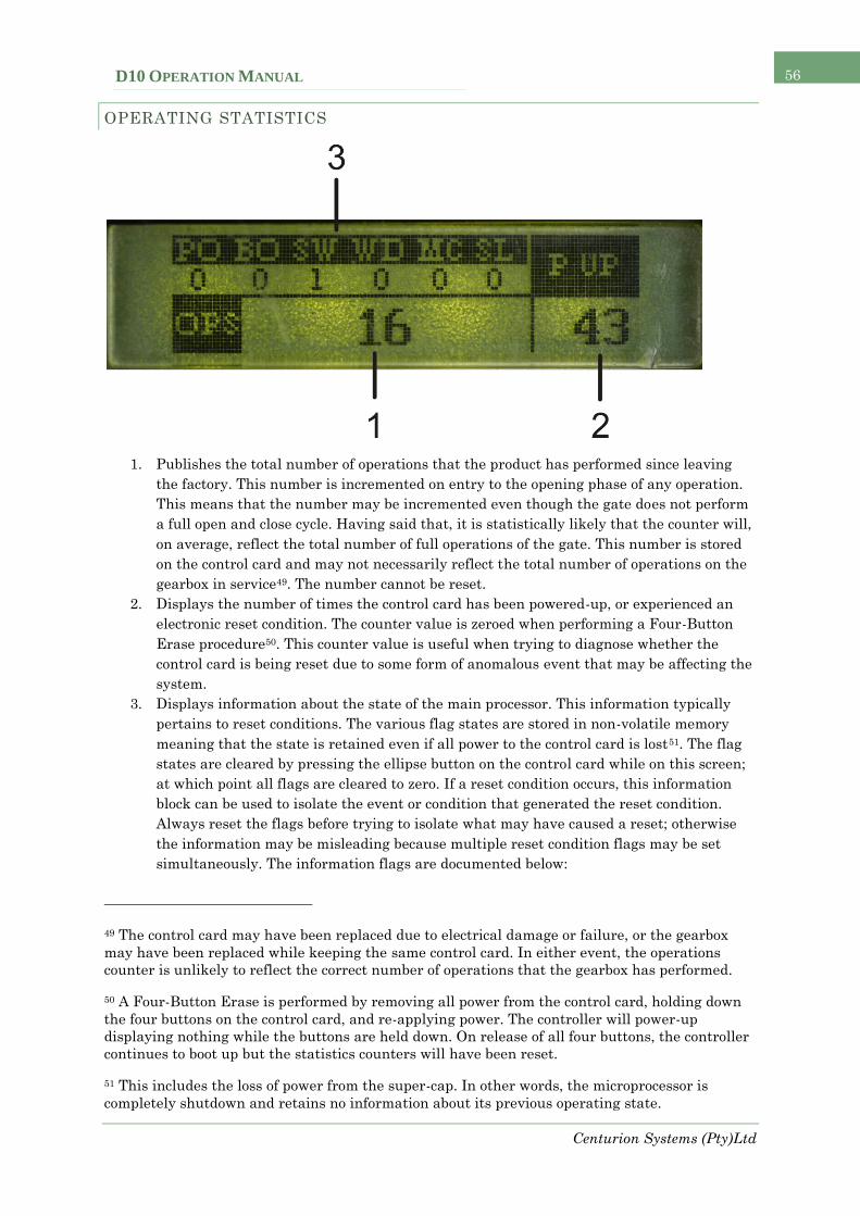
Centurion Systems (Pty)Ltd
D10 OPERATION MANUAL 56
OPERATING STATISTICS
1. Publishes the total number of operations that the product has performed since leaving
the factory. This number is incremented on entry to the opening phase of any operation.
This means that the number may be incremented even though the gate does not perform
a full open and close cycle. Having said that, it is statistically likely that the counter will,
on average, reflect the total number of full operations of the gate. This number is stored
on the control card and may not necessarily reflect the total number of operations on the
gearbox in service49. The number cannot be reset.
2. Displays the number of times the control card has been powered-up, or experienced an
electronic reset condition. The counter value is zeroed when performing a Four-Button
Erase procedure50. This counter value is useful when trying to diagnose whether the
control card is being reset due to some form of anomalous event that may be affecting the
system.
3. Displays information about the state of the main processor. This information typically
pertains to reset conditions. The various flag states are stored in non-volatile memory
meaning that the state is retained even if all power to the control card is lost51. The flag
states are cleared by pressing the ellipse button on the control card while on this screen;
at which point all flags are cleared to zero. If a reset condition occurs, this information
block can be used to isolate the event or condition that generated the reset condition.
Always reset the flags before trying to isolate what may have caused a reset; otherwise
the information may be misleading because multiple reset condition flags may be set
simultaneously. The information flags are documented below:
49 The control card may have been replaced due to electrical damage or failure, or the gearbox
may have been replaced while keeping the same control card. In either event, the operations
counter is unlikely to reflect the correct number of operations that the gearbox has performed.
50 A Four-Button Erase is performed by removing all power from the control card, holding down
the four buttons on the control card, and re-applying power. The controller will power-up
displaying nothing while the buttons are held down. On release of all four buttons, the controller
continues to boot up but the statistics counters will have been reset.
51 This includes the loss of power from the super-cap. In other words, the microprocessor is
completely shutdown and retains no information about its previous operating state.

Centurion Systems (Pty)Ltd
D10 OPERATION MANUAL 57
PO – Power-on-reset has occurred. This reset condition occurs if the control card
is powered up from a completely powered down state. Meaning that no power is
connected to the control card and the super-cap is completely discharged.
BO – A Brown-out-reset has occurred. Generally this condition occurs if the
voltage to the microprocessor drops below some critical threshold value. The
device is held in reset in such situations to prevent abnormal operation. If this
flag is set on its own, it‟s a good indicator that there may be something wrong
with the electrical supply to the operator. The system should be checked by a
qualified service technician. During a power-on-reset (see above), the BO flag is
always set simultaneously with the PO flag. This is completely normal, and
should not cause concern.
SW – A Software reset has occurred. This flag is set in the event of abnormal
software execution, device failure, or after the system powers-up following
recovery from sleep mode. The device enters sleep when all power is removed
from the controller, but the super-cap continues to power the real-time clock
circuitry. If the control card is powered up before the super-cap discharges and
the time is lost, the system will generate a software reset and set the SW flag.
WD – A Watchdog reset has occurred. This flag is set in the event of abnormal
software execution, or some form of device failure. The system should be checked
by a qualified service technician if the event is flagged repeatedly.
MC – A Master Clear reset has occurred. This flag is set in the event of abnormal
software execution, or some form of device failure. The system should be checked
by a qualified service technician if the event is flagged repeatedly.
SL – The device has entered and recovered from sleep mode. This flag is
infrequently set, as it is cleared during a device reset which usually follows the
exit from sleep mode. It is not relevant to normal controller operation, and should
not be a cause for concern if it does happen to be set.

Centurion Systems (Pty)Ltd
D10 OPERATION MANUAL 58
PRODUCT INFORMATION
1. Displays the main controller‟s firmware version. The version number is useful when
determining whether the control card software is up to date.
2. Displays the co-processor‟s firmware version number.
3. Displays the serial number of the control card. Every unit is issued with a unique serial
number. The number is displayed in hexadecimal format.
4. Displays the EEPROM version number.
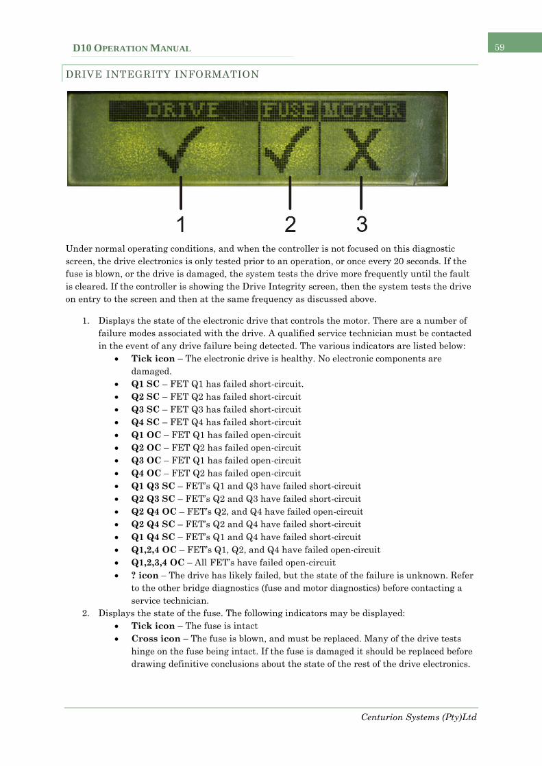
Centurion Systems (Pty)Ltd
D10 OPERATION MANUAL 59
DRIVE INTEGRITY INFORMATION
Under normal operating conditions, and when the controller is not focused on this diagnostic
screen, the drive electronics is only tested prior to an operation, or once every 20 seconds. If the
fuse is blown, or the drive is damaged, the system tests the drive more frequently until the fault
is cleared. If the controller is showing the Drive Integrity screen, then the system tests the drive
on entry to the screen and then at the same frequency as discussed above.
1. Displays the state of the electronic drive that controls the motor. There are a number of
failure modes associated with the drive. A qualified service technician must be contacted
in the event of any drive failure being detected. The various indicators are listed below:
Tick icon – The electronic drive is healthy. No electronic components are
damaged.
Q1 SC – FET Q1 has failed short-circuit.
Q2 SC – FET Q2 has failed short-circuit
Q3 SC – FET Q3 has failed short-circuit
Q4 SC – FET Q4 has failed short-circuit
Q1 OC – FET Q1 has failed open-circuit
Q2 OC – FET Q2 has failed open-circuit
Q3 OC – FET Q1 has failed open-circuit
Q4 OC – FET Q2 has failed open-circuit
Q1 Q3 SC – FET‟s Q1 and Q3 have failed short-circuit
Q2 Q3 SC – FET‟s Q2 and Q3 have failed short-circuit
Q2 Q4 OC – FET‟s Q2, and Q4 have failed open-circuit
Q2 Q4 SC – FET‟s Q2 and Q4 have failed short-circuit
Q1 Q4 SC – FET‟s Q1 and Q4 have failed short-circuit
Q1,2,4 OC – FET‟s Q1, Q2, and Q4 have failed open-circuit
Q1,2,3,4 OC – All FET‟s have failed open-circuit
? icon – The drive has likely failed, but the state of the failure is unknown. Refer
to the other bridge diagnostics (fuse and motor diagnostics) before contacting a
service technician.
2. Displays the state of the fuse. The following indicators may be displayed:
Tick icon – The fuse is intact
Cross icon – The fuse is blown, and must be replaced. Many of the drive tests
hinge on the fuse being intact. If the fuse is damaged it should be replaced before
drawing definitive conclusions about the state of the rest of the drive electronics.

Centurion Systems (Pty)Ltd
D10 OPERATION MANUAL 60
? icon – The state of the fuse is unknown. Verify the continuity of the fuse with a
multimeter to ensure that it is intact. If it is and the fuse fault is still being
displayed contact a qualified service technician.
3. Displays the state of the motor and motor connection. The following indicators may be
displayed:
Tick icon – The motor is connected, and appears to be healthy.
Cross icon – The motor is either disconnected or damaged.
? icon – The motor health and/or connectivity is unknown. Ensure that the motor
is correctly connected, and if the fault persists contact a qualified service
technician.

Centurion Systems (Pty)Ltd
D10 OPERATION MANUAL 61
REMOTE-CONTROL INFORMATION
The system stores and displays the last transmitter transaction while the controller remains
powered. This means it is possible to scroll to this screen (Remote-Control Information) and
check the last transaction that activated a function on the controller.
1. Displays the ID number of the transmitter that generated the RF transmission
2. Displays the function that was activated. The following functions may be displayed:
TRG – A RF trigger input was activated
FRX – A RF free-exit input was activated
PED – A RF pedestrian input was activated
LCK – A RF holiday-lockout input was activated
LIT – A RF courtesy-light LIT input was activated
3. Displays the button or button combination of the last RF transmission
4. Displays whether the RF transmission pulsed or latched the activated function:
Pls – The activated function was pulsed
Lat – The activated function was latched52
5. Displays whether the remote button that generated the transmission is a time-barring
button. It does not specify whether the remote was time-barred when the transaction was
generated; only that the button is associated with time-barring functionality. Two options
are possible:
Dot icon – The button is associated with time-barring functionality
No icon – The button is not associated with time-barring functionality
6. Displays whether the battery on the remote control is flat. The low-battery trip point
occurs somewhere between 7.5V and 8.5V at room temperature. Over the full
temperature range the trip point may occur anywhere between 7V and 9V. Two options
are possible:
Dot icon – The remote control‟s battery is flat and should be replaced to improve
performance
No icon – The remote control‟s battery is fine.
52 Remember that the transaction generated a latching operation. This does not imply that the
actual function is now activated. The latching operation will toggle the state of the function. If it
was off, the function will now be on. However, if it was on, it will now be off.

Centurion Systems (Pty)Ltd
D10 OPERATION MANUAL 62
7. Displays the number of buttons currently learnt into the controller‟s memory, of the total
number of buttons that may be learnt. The first number represents the number currently
learnt into memory. The number after the forward slash represents the total number of
buttons that may be learnt.

Centurion Systems (Pty)Ltd
D10 OPERATION MANUAL 63
INPUT INFORMATION
This information screen, loosely referred to as the matrix screen, displays the currently active or
inhibited inputs, and the functionality that is responsible for activating the input. The columns of
the matrix refer to the controller inputs (both RF and physical inputs). The rows refer to the
functionality that has activated or inhibited the input. The contents of the cell that is formed at
the intersection of an input and a function determines whether the function is currently affecting
the input.
1. RF - This row determines whether any inputs (in this case RF inputs), are being
activated by RF functionality. If any cell on this row has an ellipse icon in it, the
respective RF input is currently being activated. The activation may arise from a latched
remote-control transmission, or from a currently active pulsed remote-control
transmission.
2. AA – This row determines whether a physical input is being activated by an auto-
activation Time-period. Any cell with an ellipse icon in it indicates that the respective
input is active due to some currently active auto-activation Time-period.
3. TB – This row determines whether a physical input is inhibited from affecting the control
card by a time-barring Time-period. Any cell with an ellipse icon in it indicates that the
respective physical input is prevented from affecting the controller.
4. TRG – The trigger input53 column.
5. FRX – The free-exit input53 column.
6. PED – The pedestrian input53 column.
7. LCK – The holiday-lockout input53 column.
8. LIT – The courtesy light LIT input53 column.
53 In particular it‟s the RF input on the RF row, and the physical input on all other rows.