ceramic matrix composites: a challenge in space-propulsion technology applications
TRANSCRIPT
Ceramic Matrix Composites: A Challenge in Space-Propulsion Technology Applications
Stephan Schmidt,* Steffen Beyer, and Hans Immich
EADS-Space Transportation, Munich, Germany
Helmut Knabe
EADS Dornier Research and Technology, Friedrichshafen, Germany
Rolf Meistring and Andreas Gessler
EADS Corporate Research Centre, Munich, Germany
Various technology programs in Europe are concerned, besides developing reliable and rugged, low-cost, throwawayequipment, with preparing for future reusable propulsion technologies. One of the key roles for realizing reusable enginecomponents is the use of modern and innovative materials. One of the key technologies that concerns various engine man-ufacturers worldwide is the development of fiber-reinforced ceramics—CMCs (ceramic matrix composites). The advantagesfor the developers are obvious–the low specific weight, the high specific strength over a large temperature range, and their greatdamage tolerance compared with monolithic ceramics make this material class extremely interesting as a construction material.Over the past few years, the EADS-ST Company (formerly DASA) has, together with various partners, worked intensively ondeveloping components for hypersonic engines and liquid rocket propulsion systems. In the year 2000, various hot-firing testswith subscale (scale 1:5) and full-scale nozzle extensions were conducted. In this year, a further decisive milestone was achievedin the sector of small thrusters, and long-term tests served to demonstrate the extraordinary stability of the C/SiC material.Besides developing and testing radiation-cooled nozzle components and small-thruster combustion chambers, EADS-STworked on the preliminary development of actively cooled structures for future reusable propulsion systems. In order to get onestep nearer to this objective, the development of a new fiber composite was commenced within the framework of a regionallysponsored program. The objective here is to create multidirectional (3D) textile structures combined with a cost-effectiveinfiltration process. Besides material and process development, the project also encompasses the development of special metal/ceramic and ceramic/ceramic joining techniques as well as studying and verifying nondestructive investigation processes for thepurpose of testing components.
Int. J. Appl. Ceram. Technol., 2 [2] 85–96 (2005)
Ceramic Product Development and Commercialization

Introduction
Current work in the field of space propulsion tech-nology is being carried out on two different concepts:the advanced development of reliable ‘‘throwawayitems’’ paying special attention to the main aspect oflow cost, and preparation for future reusable propulsiontechnologies for multiple use (30–50 launches). Apartfrom cutting manufacturing times and costs for ‘‘throw-away items’’ for commercial launcher propulsion sys-tems, one of the main challenges comprises implement-ing a high thrust-to-mass ratio, i.e., high thrust (per-formance) with a low engine mass—kN/kg; this appliesto throwaway items as well as to future propulsionsystems. In particular, against the backdrop of reusablepropulsion system components, modern and efficientmaterials for realizing new construction concepts willplay a decisive role.
Since the early 1990s, the EADS-ST Company hasbeen working on a pacesetting key technology, namelyceramic matrix composites (CMCs). An interesting rep-resentative of the group of CMCs comprises carbonfiber-reinforced silicon carbide-C/SiC, which is madeusing the LPI process (liquid polymer infiltration).Figure 1 illustrates the excellent ratio of strength toweight, in particular at high temperatures, comparedwith currently utilized metal materials, which is just onespecial feature that makes it attractive as a constructionmaterial.1,2 In the sector of space propulsion systems, todate, ceramic fiber composites have been used primarilyfor radiation-cooled nozzle extensions and combustionchambers for small thrusters; the advantage here lies inthe low specific weight (lightweight construction), dis-pensing with active cooling and at the same time highservice temperatures.
To date, the high-temperature, lightweight materialhas become an established material in particular fornozzle extensions. Currently, commercial carbon/car-bon nozzles, manufactured by Snecma in France, arebeing used for the upper-stage engine RL10, built byPratt & Whitney, for the American launcher Delta III.
System studies undertaken at EADS-ST as well asstructural and thermal analyses promise, thanks to theuse of CMCs in thrust chambers of liquid-propellantrocket engines, substantial advantages compared withmetal materials, which are currently utilized for mostlauncher propulsion systems for the cooled combustion-chamber structures and nozzle extensions. The mainadvantages comprise on the one hand, the possible
weight reduction and on the other the high resistanceto thermoshocks as well as stability to chemical attackversus the liquid propellants used. A further significantadvantage is the high creep resistance and the extra-ordinary resistance to high temperatures compared withmetal materials. However, the multiaxis states of stressoccurring in actively cooled thrust chambers necessitatea fiber composite that features sufficient shear strengthin as many directions as possible, i.e., isotropic be-havior.3 The currently available two-directional fibercomposites would probably only have very limited life-times. For this reason, some years ago the developmentof a new material system and manufacturing process, re-spectively, was commenced, with the objective of com-bining multidirectional (3D) textile structures with acost-effective infiltration method. Besides material andprocess development, the focus is on the development ofmetal/ceramic joining techniques, engine analyses andconcepts as well as the verification of nondestructive testmethods.4,5
Due to the above advantages inherent in ceramicfiber composites, currently engine manufacturers andresearch institutes are stepping up their activities gearedtoward the use of ceramics in rocket-engine thrust-chamber components. In view of the extreme thermo-mechanical loads in the combustion chamber of liquid-propellant rocket engines, previous developments con-centrated above all on the use of ceramic fiber compos-ites in the less thermally loaded nozzle extensions.1 AtEADS-ST, nozzle extensions have been developed todate made of C/SiC for the upper-stage engine AES-TUS and successfully tested on the altitude test benchP4.1 at DLR in Lampoldshausen. A subscale nozzle on
Fig. 1. Ratio of strength to weight as a function of temperature.2
86 International Journal of Applied Ceramic Technology—Schmidt, et al. Vol. 2, No. 2, 2005
the scale of 1:5 for the Ariane 5 main engine Vulcainwas made of C/SiC and also successfully tested on theresearch test bench P8 at DLR in Lampoldshausen atcombustion-chamber pressures of up to 80 bar. Further,very successful test campaigns with radiation-cooledcombustion chambers were carried out, whereby thematerial was able to demonstrate its long-term stabilityand high chemical compatibility versus the propellantsand combustion products.
Manufacturing, Process Technique, andNondestructive Investigation (NDI) Methods
LPI Process
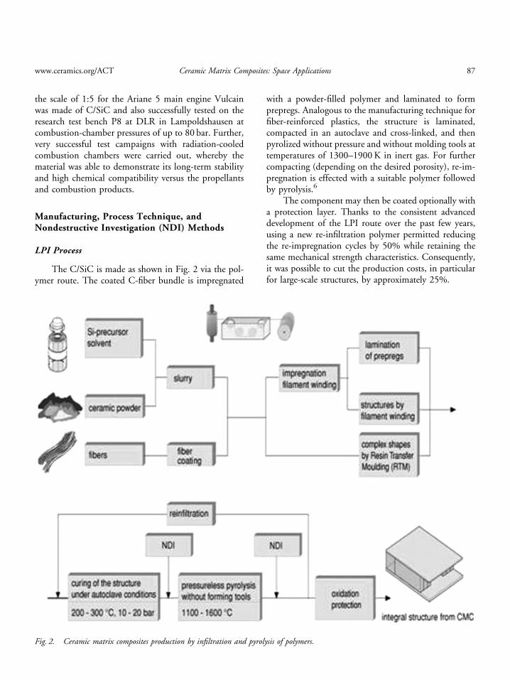
The C/SiC is made as shown in Fig. 2 via the pol-ymer route. The coated C-fiber bundle is impregnated
with a powder-filled polymer and laminated to formprepregs. Analogous to the manufacturing technique forfiber-reinforced plastics, the structure is laminated,compacted in an autoclave and cross-linked, and thenpyrolized without pressure and without molding tools attemperatures of 1300–1900K in inert gas. For furthercompacting (depending on the desired porosity), re-im-pregnation is effected with a suitable polymer followedby pyrolysis.6
The component may then be coated optionally witha protection layer. Thanks to the consistent advanceddevelopment of the LPI route over the past few years,using a new re-infiltration polymer permitted reducingthe re-impregnation cycles by 50% while retaining thesame mechanical strength characteristics. Consequently,it was possible to cut the production costs, in particularfor large-scale structures, by approximately 25%.
Fig. 2. Ceramic matrix composites production by infiltration and pyrolysis of polymers.
www.ceramics.org/ACT Ceramic Matrix Composites: Space Applications 87

NDI Methods
In view of the significantly anisotropic ceramiccomposite structure compared to metals, the non-destructive testing of C/SiC components already dur-ing production is a decisive criterion as regards the life-time and reliability of highly stressed components. Inparticular, defect interpretation and the correlation ofthe various methods are not yet completely understood.Currently, at EADS-ST diverse standard procedures forthe nondestructive testing of C/SiC components, suchas thermography, X-ray technology, and ultrasonic tech-nology, are in use. With the aid of the NDI methods,possible production defects such as delaminations,pores, and cavities, etc. as well as component condi-tions before and after testing are to be detected. In orderto improve the prediction potential and minimize risks,a comprehensive investigation program was launched ashort while ago at EADS-ST. The focus and objective ofsuch an investigation is to prepare a so-called defectcatalog that is to serve as a reference for the applicationof the different methods. Besides the above-mentionedstandard procedures, alternative methods such as com-puter and neutron tomography were studied. With re-spect to the later qualification of the individualmethods, first of all various C/SiC specimen plateswith defined, built-in defects at different depth posi-tions and with different production statuses were madeand then tested applying the NDI methods of thermo-graphy, ultrasonic testing, and computer tomography(CT). Figure 3 shows as an example the test result oftwo different plates measured on the one hand usingthermography (left-hand image) and computer tomo-graphy (right-hand image). In the thermography image(left-hand image), the differing depth position of the
artificial defects is can also be clearly seen. A decisiveadvantage of the CT measurement lies here in the exactlocalization, in particular the visualization of the depthposition of the defect, as well as in the simple estimationof the size of the defect in all three spatial directions bymeans of the reconstructed images.7
Impulse Thermography: A mobile and proven methodfor determining component qualities is impulse thermo-graphy, which has already been very successfully triedand tested in the development of nozzles and combus-tion chambers. In the case of impulse thermography, thecomponent remains stationary, and the surface of thecomponent to be tested is warmed very homogeneouslywith special flashbulb heat in the milli-to-microsecondrange by some few degrees. If no differences in materialor structural damage such as, for instance, delamina-tions, occur, this thermal impulse penetrates uniformlyinto the material. If, for instance, there are delamina-tions or other defects in the composite material, at thisspot the thermal conductivity is disturbed and visualizedvia special software by means of differing color codings.
CT: CT makes it possible to visualize the interiorstructure of objects nondestructively and without con-tact. By applying the latest technologies and faster al-gorithms, a spatial resolution of up to 1 mm and less isachieved. As, for instance, the C/SiC combustion cham-bers represent 3D axisymmetric bodies, the industrial3D computer tomography method is extremely advan-tageous. The system permits detecting changes in den-sity as well as defects, together with a characterizationwith respect to their type, geometry, and position in thecomponent. It is therefore possible to visualize materialdefects in the component volume, to effect local reso-lution, and hence to make a comprehensive statement asregards quality. In addition, a dimensional measure-ment, i.e., a complete, quantitative coverage of the con-
Fig. 3. Testing various specimen plates by means of thermographyand computer tomography. Fig. 4. Measurement principle of 3D computer tomography.
88 International Journal of Applied Ceramic Technology—Schmidt, et al. Vol. 2, No. 2, 2005

tour, can be effected. Downstream data processing canthus serve to determine wall thicknesses and representnominal-actual contour comparisons. Figure 4 illus-trates this principle.8 Through the continuous advanceddevelopment of the industrial CT systems, in particularof the detectors, components that are 800� 800mm insize can be tested.
Development and Test of CMC Components
Vulcain Subscale Nozzle Extension
Within the framework of the TEKAN and ASTRAProgramme, two Vulcain (main stage engine of Ariane5) subscale nozzles on the scale of 1:5 and with an arearatio of e5 5–45 were designed, made using the LPItechnique and subjected to hot-firing testing on theEADS-ST test bench F3 (Ottobrunn) as well as on theDLR test bench P8.
The development and test objectives of the C/SiCnozzle extension were:
� To study the compatibility and function of ox-idation/erosion protection coatings for different mixtureratios (o/f5 5–8).
� Investigation into nozzle flow, flow separation(transient, steady).
� Comparison with Vulcain (full-scale) lateralloads/separation data.
� Upgrading/verifying of design tools (heat transi-tion, separation, side load).
� Qualification of measurement technology (pres-sure sensors at wall).
� Investigation into material behavior under ex-treme thermal–mechanical conditions.
� Manufacturing of complex contours with adapt-ed stiffener rings for buckling loads.
� Demonstration and verification of the metallic/ceramic joining technique.
Manufacturing and Design: Based on the thermal andstructure-mechanical analyses, two Vulcain scaled noz-zles were made applying the LPI method. The requiredfiber angle and the wall-thickness distribution of thenozzle component were set via the winding technique soas to be tailor-made. Due to the side loads calculated,special stiffener elements were necessary in order to pre-vent buckling of the nozzle. By laminating on ring el-ements and subsequent aging and pyrolysis, an integralpositive compound between nozzle and stiffening ele-
ment was generated. For manufacturing the two noz-zles, a newly developed polymer system was used thatpermitted reducing the manufacturing time by ap-proximately 30% compared with the old polymer.Both nozzles were coated for the hot-firing tests with aCVD–SiC layer. One of the challenges involved the in-terface design between ceramic nozzle and metal com-bustion chamber. In particular, the high temperaturesoccurring at the interface in the case of an area ratio of 5represented a particular challenge. Thanks to an angularflange design, the use of flexible high-temperature seals,and special clamping rings, the problem could be solved.Figure 5 shows the two coated C/SiC nozzle extensions.
Hot-Firing Tests: The Vulcain subscale nozzle exten-sion was tested in two test sequences, one with a max-imum chamber pressure of pc5 40 bar, and a secondtest sequence that comprised one single load point, withpc5 80 bar and o/f5 6, for the entire test duration of32 s, which was sufficient to have full-flowing condi-tions in the nozzle extension installed.The 40-bar load case was specially performed to vis-
ualize the transition process from free to restricted shockseparation, which is typical of parabolic rocket nozzles,i.e., the Vulcain or SSME type. Figures 6 and 7 showthe nozzle extensions on test bench F4 and during the40-bar hot-firing test.During the F3 hot-firing test (40 bar), particularly in
the transition range from free to restricted shock sepa-ration, temperatures of up to 2300K were measured on
Fig. 5. Vulcain subscale C/SiC nozzle extensions (1:5).
www.ceramics.org/ACT Ceramic Matrix Composites: Space Applications 89

the hot-gas side by means of thermography. In additionto the high wall temperatures, large thermal gradientsoccurred, especially in the sector of the stiffening ele-ments. Temperature measurements yielded gradients ofup to 650K. Figure 8 illustrates the high combustion-chamber pressure test with pc5 80 bar at H0110 s. Theexhaust plume with the typical cap-shock pattern isclearly visible. Additionally, the thermographical imag-ing lens system is shown, pointing nearly perpendicu-larly to the outer surface of the nozzle. The nozzleextension withstood the transition process withoutstructural damage.
Summary: Design challenge involving ceramic sub-scale nozzle for first- or booster-stage application suc-cessfully demonstrated:
� Side-load case during transient start-up andshut-down.
� Maximum buckling load case due to integralpressure difference between inner and outer nozzle wallwith strongly overexpanded core flow.
� Function of metallic/ceramic joining techniqueunder real conditions.
� Manufacturing of tailor-made ceramic structureswith adapted stiffeners based on thermal and structuralcalculations.
� C/SiC material withstood high wall temperatures(� 2300K) and thermal gradients, especially for highestheat flux measured with restricted shock separation.
� Test results show excellent scalability of flowphenomena to full scale, e.g.,
� transition from free to restricted shock separation,� plume pattern for overexpanded core flow oper-
ation, cap-shock pattern, and Mach disk.� To the best of our knowledge, world record
test with ceramic nozzle extension, with regard to com-bustion chamber pressure and operational load case.
� Knowledge gained at EADS-ST in designing,manufacturing, and testing of ceramic subscale Vulcainnozzle, can be applied directly to nozzle design for fur-ther first-or booster-stage nozzles, e.g., SSME type.
� Flow features, i.e., free and restricted shock sep-aration, for SSME are identical to Vulcain, due to par-abolic nozzle contours.
� Dimensioning load cases for SSME-type ceramicnozzle are identical with successfully tested Vulcain-typeceramic nozzle.
Aestus Nozzle Extension
In 1998, development work on the C/SiC exten-sion nozzle commenced, the objective being to demon-strate the basic feasibility of making full-scale
Fig. 6. Vulcain subscale nozzle on test bench F3 in Ottobrunn.
Fig. 7. Vulcain subscale nozzle during 40 bar hot-firing test (F3).
Fig. 8. Vulcain subscale nozzle on DLR test bench P8.
90 International Journal of Applied Ceramic Technology—Schmidt, et al. Vol. 2, No. 2, 2005

components by means of the LPI process. A main focuswas the design (FEM, thermal) of fiber composite struc-tures taking into consideration the loads (vibration, etc.)occurring in the case of Ariane 5. Further developmentand test objectives were:
� Preparation of future developments in the area ofliquid propulsion.
� Verification of interface design—joining tech-nique between ceramic nozzle and metal combustionchamber.
� Optimization of the design tools (FEM andthermal).
� Comparison between Aestus test results andstandard construction (metal nozzle).
� Verification of reproducibility with respect to themanufacture of complex large-scale structures made ofC/SiC applying the LPI process.
� Optimization of the process route by using newlydeveloped polymer systems.
� Implementation of a material characterizationprogram to determine material characteristics (creeptests, ILS, thermal conductivity) of the original nozzlelaminate.
Figure 9 shows a section drawing of Aestus enginewith C/SiC nozzle extension.
Manufacturing and Design: The leap from subscale tolarge structures such as the Aestus nozzle represented aparticular problem. Especially the process-induced com-ponent shrinkage occurring during manufacture and asa function of the fiber orientation had to be solved dur-ing production development with a special emphasis onadherence to the geometrical tolerances.Based on the FEM and thermal analyses, the required
fiber angle and the wall-thickness progression of theAestus nozzle were set via the winding technique, as forthe Vulcain subscale nozzle. Thanks to this tailor-madecomposite layup, the nozzle contour could be made soas to be near net shape as well as weight-optimized.Figure 10 illustrates how the fibers are laid up by meansof the winding technique at the Friedrichshafen Pro-duction Centre. The loads occurring on launching theAriane necessitate providing a stiffening ring at the endof the nozzle. In contrast to the nozzle structure, thestiffening ring was made by means of the prepreg tech-nique. Figure 11 shows prepreg manufacture on the left-hand side; on the right-hand side the stiffening ring isshown on the layup tool. The ring and nozzle werejoined subsequently.
Since development was launched, altogether five noz-zle hardware units have been made applying the LPIprocess. Thanks to continuous optimization of the pro-duction and process techniques, production time wascut by approximately 30%. The first hot-firing test tookplace in the year 2000.
Hot-firing Test: Within the framework of the testprogram, funded in-house, the structural integrity ofand the thermal load on the C/SiC nozzle extensionwere verified in a sine-load vibration and vacuum hot-firing test. The test was performed on the DLR’s P4.2test facility in Lampoldshausen in the year 2000.The scheduled and realized test time amounted to
150 s at a combustion-chamber pressure of 11 bars andwith a mixture ratio (o/f ) of 2.05. Figure 12 shows onthe left-hand side the integrated ceramic nozzle on theP4.2 and on the right-hand side during the vacuum test.
Summary: The use of nozzle extensions made of C/SiC for upper-stage engines was successfully demon-strated with respect to:
� Mechanical loads during the transient start-upand shut-down phase.
Fig. 9. Section drawing of Aestus engine with C/SiC nozzle.
www.ceramics.org/ACT Ceramic Matrix Composites: Space Applications 91

� Manner of functioning of the metal/ceramic in-terface.
� Manufacture of a tailor-made ceramic structurewith adapted stiffening ring.
� Design, manufacture, and hot-firing test of full-scale nozzle components.
� Weight reduction (60% compared with metalnozzle).
400 N Combustion Chamber
Combustion chambers for apogee- and attitude-control engines for satellites are currently made ofrefractory heavy metals such as rhenium, iridium, andplatinum. Due to the high stability to chemical attackand high service temperature of up to 1850K, the re-
fractory metals are used as the material for combustionchambers. Besides high material and manufacturingcosts as well as the substantial use of raw materials,heavy metals exhibit a high density, amounting to morethan 21 g/cm3. Figure 13 depicts the current 400N en-gine (flight version).
The potential offered by CMCs as a structural ma-terial for small thrusters lies among other things in theclearly lower manufacturing costs compared with metalconstruction. Further advantages comprise:
� Simplification of the construction method by re-ducing the individual components (single-piece con-struction), hence reduced test effort.
� Increase in the permissible wall temperatures ofcurrently 1900K to � 2200K (with suitable layer sys-tem), hence increase in specific impulse (performance).
� Reduction of engine mass of 30–50%.
Fig. 10. Production of the Aestus nozzle structure by means of thewinding technique at the Friedrichshafen Production Centre.
Fig. 11. Prepreg manufacture (on the left) and laminatedstiffening ring (on the right).
92 International Journal of Applied Ceramic Technology—Schmidt, et al. Vol. 2, No. 2, 2005

In order to study the use of fiber-composite ceram-ics for small thrusters, in 1998 the first hot-firing testswere carried out at sea level with different C/SiCcombustion chambers. The propellant compatibility(MMH/N2O4), diverse clamping concepts, and inves-tigation of differing layer systems with regard to long-term deployment comprised the main areas of effort.The accumulated test time amounted to 3200 s at acombustion-chamber pressure of 10 bar. By varying themixture ratio (o/f ) in the range between 1.64 and 1.92,maximum wall temperatures of up to 17001C were de-termined. Further hot-firing tests with modified andoptimized combustion chambers (Fig. 14) as well asnewly developed layer systems were carried out. Themain objective of the material and component tests wasto verify the long-term behavior (41 h) and to find outthe maximum permissible component temperatures.The test time amounted to 5700 s at a combustion-chamber pressure of 11 bar.
Figure 15 shows the combustion chamber duringthe hot-firing test.
The hot-firing tests conducted since 1998 withcoated combustion chambers made of C/SiC yieldedimportant insights into the application potential ofCMCs for small thrusters. The feasibility together withthe positive effects on engine performance was verified.
Based on these experiences the development in thefield of satellite propulsion is continued. For the dem-onstration of the feasibility of manufacturing a ceramiccombustion chamber with the nozzle extension as a sin-gle-piece construction in 2003/2004, a demo enginewas manufactured, illustrated in Fig. 16.
Further Developments
In the course of developing cost-effective manufac-turing methods for structural components made of fibercomposites, in recent years various textile productionmethods for processing carbon fibers have been devel-oped further and innovative machine concepts elabo-rated for making special semifinished products. Newbraiding techniques offer extremely productive methodsfor making contoured fiber preforms such as combus-tion chambers or nozzles.
Thus the 3D braiding technique offers quite a fewadvantages. 3D braided profiles can be varied in shapeand cross section and are characterized by high struc-tural integrity and tolerance, as the braiding threads canbe led laterally through the component wall, thus rep-resenting a reinforcement in thickness direction. Thanks
Fig. 12. Ceramic nozzle on test bench 4.2 (left-hand side) andduring the vacuum hot-firing test.
Fig. 13. 400 N engine (flight version).
www.ceramics.org/ACT Ceramic Matrix Composites: Space Applications 93

to using sewing threads made of carbon fiber, cost-ef-fective, tailor-made 3D reinforcements for tensile andshear loads can be created. The actual innovation withthis material development is the combination of an ex-tremely cost-effective infiltration method with the tex-tile technique for making multidirectional fiber-composite ceramics. Figure 17 shows the 3D braidingfacility at EADS Research (Ottobrunn) and Fig. 18 de-picts the robot-assisted stitching machine.
Within the scope this development program, in-tensive work is being carried out, in addition to thematerial and process development, on metal/ceramicjoining techniques based on the active brazing methodand electroplating. Thereby a structuring of the C/SiCsurface is superposed to the joining techniques so thatthe connection between metal and ceramic is improved.The method of the production of the joining is similarfor all processes. At first a brazing-alloy layer or a braz-ing-alloy-mat is brazed on the C/SiC component to re-alize a metallizing of the ceramic surface. In a furtherstep, a ‘‘metal–metal’’ joining is produced by a furtherbrazing process or by a galvanic process. From formerprograms, there is a well-founded know-how at EADS-ST in the area of such joining techniques.
In the frame of a common development program ofMBDA-France, EADS-ST France, EADS-ST Germany,and EADS Common Research Center Germany, fuel-cooled combustion chamber structures for hypersonicDual-Mode Ramjets (PTAH-SOCAR technology) be-
come manufactured by a combination of textile tech-niques of EADS-ST France (AEROTISSs material)and the above-mentioned low-cost LSI process.
Summary
New, innovative approaches must be followed inthe area of material development in order to addition-ally create, besides the customary one-way engine com-ponents, reusable propulsion technologies for thefuture. In this context, using fiber-reinforced ceramics,in particular C/SiC ceramics, is becoming increasinglyobvious—thanks to their outstanding thermophysicaland mechanical characteristics—as being the optimalsolution.
Within the framework of hot-firing testing, fundedin-house, C/SiC nozzle extensions for upper- and lower-stage engines as well as C/SiC combustion chambers for
Fig. 14. Modified C/SiC combustion chambers coated withdifferent layers.
Fig. 15. Modified C/SiC combustion chamber during the hot-firing test.
94 International Journal of Applied Ceramic Technology—Schmidt, et al. Vol. 2, No. 2, 2005

small thrusters (400N) were designed, manufacturedand successfully subjected to hot-firing testing.
The components were manufactured correspondingto the laminating technique from CFRP technology ap-plying the so-called liquid polymer Infiltration process.In order to determine the specific characteristics and tomonitor the quality, various destructive as well as non-destructive test measures were carried out.
In hot-firing tests, the performance together withthe long-term loadability of the diverse components wasanalyzed. For instance, temperatures of up to 2300Kand thermal gradients in the component of up to 650Kwere detected for the Vulcain subscale nozzle (originalcontour on the scale of 1:5) in two test series undervarious conditions, such as an internal chamber pressure
of 40 and 80 bar. This served to verify the feasibility ofcomplex nozzle components made using the LPI route.
For the upper-stage engine AESTUS with a fiber-reinforced ceramic nozzle of the original size, the highdamage tolerance as well as the resistance of the com-ponent to elevated temperatures were demonstrated suc-
Fig. 16. Single piece 400 N second-generation combustionchamber with nozzle extension (current version).
Fig. 17. 3D braiding facility EADS Research, Ottobrunn.
Fig. 18. Robot-stitching machine.
www.ceramics.org/ACT Ceramic Matrix Composites: Space Applications 95

cessfully in a combined 150-s long hot-firing test in avacuum with an internal chamber pressure of 11 bar.
In order to obtain statements about deploymentas a material for combustion chambers in addition tothe usability of fiber-reinforced ceramics in the nozzle-extension sector, various hot-firing test campaignsto determine temperature limits and long-term be-havior with given operating parameters were performedfollowing the manufacture of small 400N ceramicthrusters.
Since the start of development, test times of 8900 s(approximately 2.5 h) at wall temperatures of up to2000K and combustion-chamber pressures of 10–11bar were reached within the scope of various test cam-paigns. With regard to advanced combustion chambers,the structural integrity was proven even in the case ofthe most stringent requirements.
With the objective of consolidating competenciesin the sector of fiber-reinforced ceramics, a new, inno-vative technology program was launched in order tocombine textile techniques with special infiltration
methods, hence creating a cost-effective and at thesame time high-performance material.
References
1. J. Alting, F. Grauer, G. Hagemann, and J. Kretschmer, ‘‘Hot-Firing of anAdvanced 40 kN Thrust Chamber,’’ AIAA 2001-3260, July 2001.
2. Boeing.3. S. Beyer, H. Knabe, and F. Strobel, ‘‘Development and Testing of C/SiC
Components for Liquid Rocket Propulsion Applications,’’ AIAA 99–2896,June 1999.
4. J. Brandt, K. Drechsler, and R. Meistring, ‘‘The Application of Three-Di-mensional Fibre Preforms for Aerospace Composite Structures,’’ Proceedingsof the ESA Symposium—Space Applications of Advanced Structural Material,ESTEC Noordwijk/NL, 71–77, 1990.
5. W. Krenkel, and P. Schanz, ‘‘Fiber Ceramic Structures Based on Impregna-tion Technique,’’ 42nd Congress of the International Astronautical Federation,Montreal, 1–11, 1991.
6. P. Greil, ‘‘Polymerkeramik. 47. Erg.-Keramische Werkstoffe,’’ TechnischeKeramik, 2.AuflageHrsg. ed. J. Kriegesmann. Vulkan Verlag, Essen, 1998.
7. ‘‘ZfP Einfuhrung,’’ Deutsche Gesellschaft fur Zerstorungsfreie Prufunge.V. (DGZfP), http://www.dgzfp.de/?page=dgzfp/allgemein/zfpeinfuehrung(06.02.04).
8. G. Maier and B. Fruehauf (Daimler Benz, Stuttgart), ‘‘Computed Tomo-graphy in the Automotive Industry—Experience with Industrial Applica-tions,’’ International Symposium on Computerized Tomography for IndustrialApplications and Image Processing in Radiology, Berlin, Germany, March15–17, 1999.
96 International Journal of Applied Ceramic Technology—Schmidt, et al. Vol. 2, No. 2, 2005