ceramic resonators ('ceralock') - farnell element14 · !note • please read rating and...
TRANSCRIPT
Cat.No.P16E-17
MurataManufacturing Co., Ltd.
Ceramic Resonators(CERALOCKr)
• This PDF catalog is downloaded from the website of Murata Manufacturing co., ltd. Therefore, it’s specifications are subject to change or our products in it may be discontinued without advance notice. Please check with our sales representatives or product engineers before ordering.
• This PDF catalog has only typical specifications because there is no space for detailed specifications. Therefore, please approve our product specifications or transact the approval sheet for product specifications before ordering.
!Note P16E.pdf06.9.7

1
2
3
4
5
6
7
1
2
3
4
5
6
7
Selection Guide 2
Part Numbering 3
MHz Chip Type -Tight Frequency Tolerance for Automotive- 4
Application Circuits Utilization 6
MHz Chip Type -Standard Frequency Tolerance for Automotive- 7
Application Circuits Utilization 11
MHz Chip Type Notice (Soldering and Mounting) for Automotive 12
MHz Chip Type Notice for Automotive 16
MHz Chip Type Packaging for Automotive 17
MHz Chip Type -Tight Frequency Tolerance for General Usage- 19
Application Circuits Utilization 23
MHz Chip Type -Standard Frequency Tolerance for General Usage- 24
Application Circuits Utilization 29
MHz Lead Type -Standard Frequency Tolerance for General Usage- 31
kHz Chip Type -Standard Frequency Tolerance for General Usage- 33
kHz Lead Type -Standard Frequency Tolerance for General Usage- 35
MHz Chip Type Notice (Soldering and Mounting) for General Usage 37
MHz Chip Type Notice for General Usage 42
MHz Lead Type Notice for General Usage 43
kHz Type Notice for General Usage 44
MHz Chip Type Packaging for General Usage 48
MHz Lead Type Packaging for General Usage 51
kHz Type Packaging for General Usage 54
CERALOCKr and "CERALOCK" in this catalog arethe trademarks of Murata Manufacturing Co., Ltd.
CONTENTS
!Note • Please read rating and !CAUTION (for storage, operating, rating, soldering, mounting and handling) in this catalog to prevent smoking and/or burning, etc.• This catalog has only typical specifications because there is no space for detailed specifications. Therefore, please approve our product specifications or transact the approval sheet for product specifications before ordering.
Recycled Paper
• This PDF catalog is downloaded from the website of Murata Manufacturing co., ltd. Therefore, it’s specifications are subject to change or our products in it may be discontinued without advance notice. Please check with our sales representatives or product engineers before ordering.
• This PDF catalog has only typical specifications because there is no space for detailed specifications. Therefore, please approve our product specifications or transact the approval sheet for product specifications before ordering.
!Note P16E.pdf06.9.7

2
Start
Applications
FunctionsFunctions
Frequencies
SMDSMDSMDSMD LeadedSMDLeadedSMD
Consumer Automotive
Full Speed USB (high-precision)
AutomotiveNetwork
(high-precision)
Card (small, low-profile)
General Usage
MHzkHz
OtherAutomotive Usage
CSBFB_J430–519kHz
CSBLA_E375–429kHz
CSTCC_G2.00–3.99MHz
CSTLS_G3.40–10.00MHz
CSTCR_G15ppp6.00MHz
CSTCE_G8.00–13.99MHz
CSTCC_G_A2.00–3.99MHz
CSTCR_G15Bpp4.00–7.99MHz
CSBFB_J700–1250kHz
CSBLA_E430–509kHz
CSTCR_G4.00–7.99MHz
CSTLS_X16.00–70.00MHz
CSTCE_G15Lpp12.00MHz
CSTCE_V14.00–20.00MHz
CSTCR_G_B4.00–7.99MHz
CSTCE_G15Cpp8.00–13.99MHz
CSBLA_E510–699kHz
CSTCE_G8.00–13.99MHz
CSALS_X16.00–70.00MHz
CSTCE_V13Lpp16.00MHz
CSTCG_V20.00–33.86MHz
CSTCE_G_A8.00–13.99MHz
CSBLA_J700–1250kHz
CSTCE_V14.00–20.00MHz
CSTCW_X20.01–70.00MHz
CSACW_X20.01–70.00MHz
The kHz resonators have only two terminals.
(Two Terminals)
(Two Terminals)
CSTCW_X11ppp24.00MHz
CSTCZ_X12Rpp48.00MHz
CSTCE_V13Cpp14.00–20.00MHz
CSTCW_X_M25.00–48.00MHz
CSTCV_X_Q20.01–70.00MHz
CSACV_X_Q20.01–70.00MHz(Two Terminals)
CSTCE_V_C14.00–20.00MHz
SMD
High Speed USB (high-precision)
CSTCE_XKpppp24.00/30.00MHz
p: Alphanumerics express individual specification
Selection Guide
!Note • Please read rating and !CAUTION (for storage, operating, rating, soldering, mounting and handling) in this catalog to prevent smoking and/or burning, etc.• This catalog has only typical specifications because there is no space for detailed specifications. Therefore, please approve our product specifications or transact the approval sheet for product specifications before ordering.
• This PDF catalog is downloaded from the website of Murata Manufacturing co., ltd. Therefore, it’s specifications are subject to change or our products in it may be discontinued without advance notice. Please check with our sales representatives or product engineers before ordering.
• This PDF catalog has only typical specifications because there is no space for detailed specifications. Therefore, please approve our product specifications or transact the approval sheet for product specifications before ordering.
!Note P16E.pdf06.9.7
Notice) "CERALOCKr for general usage" and "CERALOCKr for automotive" is different in the specification of Operating Temperature Range, Environmental Characteristics, Physical Characteristics and so on. Please choose either "for general usage" or "for automotive" according to the required specification.

3
o Part Numbering
!Note • Please read rating and !CAUTION (for storage, operating, rating, soldering, mounting and handling) in this catalog to prevent smoking and/or burning, etc.• This catalog has only typical specifications because there is no space for detailed specifications. Therefore, please approve our product specifications or transact the approval sheet for product specifications before ordering.
qProduct ID
wFrequency/Capacitance
eStructure/Size
tDesign
oPackaging
CERALOCKr (MHz)
CS Ceramic Resonators
Gpp
T/Vpp
Xpp
A
T
MHz No capacitance built-in
MHz Built-in Capacitance
LS
CC
CR/CE/CG
CV
CW
Round Lead Type
Cap Chip Type
Small-cap Chip Type
Monolithic Chip Type
Small Monolithic Chip Type
Thickness Shear mode
Thickness Expander mode
Thickness Expander mode (3rd overtone)
Three-digit alphanumerics express"Individual Specification".
Structure/Size
-B0
-A0
-R0
-R1
Packaging
Product ID
Code
Code
Code
iIndividual Specification
***
Code
Frequency/Capacitance
Design
Individual Specification
Code
(Part Number)
rNominal Center Frequency
Expressed by four-digit alphanumerics. The unit is in hertz (Hz). Decimal point is expressed by capital letter "M".
With standard products, "iIndividual Specification" is omitted, and "oPackaging" is carried up.
Bulk
Radial Taping H0=18mm
Plastic Taping ø=180mm
Plastic Taping ø=330mm
yInitial Frequency Tolerance
5
3
2
1
H
K
DesignCode
±0.5%
±0.3%
±0.2%
±0.1%
±0.07%
-0.025/0.02%
uLoad Capacity
1
2
3
4
5
6
DesignCode
5pF
10pF
15pF
22pF
30/33/39pF
47pF
e
CE
w
T
r
16M0
q
CS
pp indicates initial frequency tolerance and load capacity.
Radial taping is applied to lead type and plastic taping to chip type.
i
***
t
V
y
5
u
3
o
-R0
y
***
e
FB
w
B
r
500K
t
J58
u
-R1
q
CS
qProduct ID
wFrequency/Capacitance
eStructure/Size
rNominal Center Frequency
tDesign
uPackaging
CERALOCKr (kHz)
CS Ceramic Resonators Epp
Jpp
B kHz No capacitance built-in
LA
FB
Two-Terminal Lead Type
SMD Type
Area Expansion mode
Area Expansion mode (Closed Type)
Three-digit alphanumerics express "Individual Specification".Structure/Size
-B0
-R1
Packaging
Product ID
Code
Code
Code
yIndividual Specification
***
Code
Frequency/Capacitance
Design
Individual Specification
Code
(Part Number)
Expressed by four-digit alphanumerics. The unit is in hertz (Hz). Capital letter "K" following three figures expresses the unit of "kHz". In case of 1.0MHz (1000kHz) or above, expressed by three figures and capital letter "M" for decimal point.
With standard products, "yIndividual Specification" is omitted, and "uPackaging" is carried up.
Bulk
Plastic Taping ø=330mm
pp indicates initial frequency tolerance and load capacitance.
• This PDF catalog is downloaded from the website of Murata Manufacturing co., ltd. Therefore, it’s specifications are subject to change or our products in it may be discontinued without advance notice. Please check with our sales representatives or product engineers before ordering.
• This PDF catalog has only typical specifications because there is no space for detailed specifications. Therefore, please approve our product specifications or transact the approval sheet for product specifications before ordering.
!Note P16E.pdf06.9.7

4
1
!Note • Please read rating and !CAUTION (for storage, operating, rating, soldering, mounting and handling) in this catalog to prevent smoking and/or burning, etc.• This catalog has only typical specifications because there is no space for detailed specifications. Therefore, please approve our product specifications or transact the approval sheet for product specifications before ordering.
Ceramic Resonators (CERALOCKr)MHz Chip Type -Tight Frequency Tolerance for Automotive-
Chip type "CERALOCK" with built-in load capacitors in an extremely small package provides high accuracy.MURATA's frequency adjustment and package technology expertise has enabled the development of the chip "CERALOCK" with built-in load capacitors.Chip "CERALOCK" for automotive has achieved importancein the worldwide automotive market. This diverse series owes its development to MURATA's original mass production techniques and high reliability.
Features1. The series are high accuracy resonators whose total tolerance is available for less than +-3,000ppm. 2. The series has high reliability and is available for wide temperature range.3. Oscillation circuits do not require external load capacitors.4. The series is available for a wide temperature range.5. The resonators are extremely small and have a low profile.6. No adjustment is necessary for oscillation circuits.
Applications1. Cluster panel and Control panel2. Safety control (Anti-lock Brake System, Electronic Stability Control, Airbag, etc.)3. Engine ECU, Electronic Power Steering, Immobilizer, etc.4. Car Air-conditioner, Power window, Remote Keyless Entry system, etc.5. Intelligent Transportation System (Lane Keeping System, Millimeter wave radar, etc.)6. Battery control for hybrid car
4.5±0.1
∗
4.1 max.
0.8±0.1
0.75±0.1 1.5±0.1 1.5±0.1
0.4±0.1 0.4±0.1 0.4±0.1
0.8±0.1 0.8±0.1
0.4 (ref.)0.4 (ref.)0.4 (ref.)
0.4±0.050.2±0.2
0.3±
0.2
2.0±
0.1
1.4
max
.
(2) (1)(3)
1.15
±0.0
5 ∗ : EIAJ Monthly Code
(in mm)
CSTCR_G15B4.00-7.99MHz
3.2±0.15
1.3±
0.15
0.50 (ref.)
0.50 (ref.)
0.50 (ref.)
3.0 max.
0.10
±0.1
0
0.4±0.1
0.4±0.1 1.2±0.1 1.2±0.1
(1)(2)(3)
0.1±0.1
1.1
max
.
0.4±0.1
0.70
±0.1
0
0.4±0.1 0.4±0.1
(in mm)
∗
CSTCE_G15C8.00-13.99MHz
3.2±0.15
0.10
±0.1
0
0.1±0.1
1.3±
0.15
1.1
max
.
0.4±0.1
0.5 (ref.) 0.5 (ref.)
0.9±
0.1
3.0 max.
0.4±0.1(1)(2)(3)
0.4±0.1 1.2±0.1 1.2±0.1
0.4±0.10.4±0.1
0.5 (ref.)
(in mm)
CSTCE_V13C14.00-20.00MHz
Part NumberOscillatingFrequency
(MHz)
InitialTolerance
Temp. Stability(%)
TemperatureRange
(°C)
CSTCR_G15B 4.00 to 7.99 ±0.1% ±0.15 -40 to 125
CSTCE_G15C 8.00 to 13.99 ±0.1% ±0.13 -40 to 125
CSTCE_V13C 14.00 to 20.00 ±0.1% ±0.13 -40 to 125
Irregular or stop oscillation may occur under unmatched circuit conditions. Please check the actual conditions prior to use.
• This PDF catalog is downloaded from the website of Murata Manufacturing co., ltd. Therefore, it’s specifications are subject to change or our products in it may be discontinued without advance notice. Please check with our sales representatives or product engineers before ordering.
• This PDF catalog has only typical specifications because there is no space for detailed specifications. Therefore, please approve our product specifications or transact the approval sheet for product specifications before ordering.
!Note P16E.pdf06.9.7

5
1
!Note • Please read rating and !CAUTION (for storage, operating, rating, soldering, mounting and handling) in this catalog to prevent smoking and/or burning, etc.• This catalog has only typical specifications because there is no space for detailed specifications. Therefore, please approve our product specifications or transact the approval sheet for product specifications before ordering.
Oscillation Frequency Measuring Circuit
VDD
RfTo Frequency Counter
5pF
1MΩ
Rd
C1 C2
(1) (3)
(2)
Standard Land Pattern DimensionsCSTCR_G15B
2.6
1.6
0.8
0.4
1.5 1.5
0.4 0.4
0.8 0.80.70.7
Land Pattern
(in mm)
CSTCE_G15C
0.4
1.90
~ 2
.10
0.4 0.40.8
Land Pattern
0.8
1.2 1.2
(in mm)
CSTCE_V13C
0.4
1.90
~ 2
.10
0.4 0.40.8
Land Pattern
0.8
1.2 1.2
(in mm)
Oscillation Frequency Temperature StabilityCSTCR_G15B
-60 -40 -20 0 +20 +40 +60 +80 +100 +120 +140
Osc
illat
ing
Fre
quen
cy S
hift
(%)
+0.2
+0.1
0
-0.1
-0.2
Temperature (°C)
CSTCE_G15C
-60 -40 -20 0 +20 +40 +60 +80 +100 +120 +140
Osc
illat
ing
Fre
quen
cy S
hift
(%)
Temperature (°C)
+0.2
+0.1
0
-0.1
-0.2
CSTCE_V13C
-60 -40 -20 0 +20 +40 +60 +80 +100 +120 +140
Osc
illat
ing
Fre
quen
cy S
hift
(%)
+0.2
+0.1
0
-0.1
-0.2
Temperature (°C)
• This PDF catalog is downloaded from the website of Murata Manufacturing co., ltd. Therefore, it’s specifications are subject to change or our products in it may be discontinued without advance notice. Please check with our sales representatives or product engineers before ordering.
• This PDF catalog has only typical specifications because there is no space for detailed specifications. Therefore, please approve our product specifications or transact the approval sheet for product specifications before ordering.
!Note P16E.pdf06.9.7

Application Circuits Utilization
6
1
!Note • Please read rating and !CAUTION (for storage, operating, rating, soldering, mounting and handling) in this catalog to prevent smoking and/or burning, etc.• This catalog has only typical specifications because there is no space for detailed specifications. Therefore, please approve our product specifications or transact the approval sheet for product specifications before ordering.
TMP92CD54IF (Toshiba)16-bit Microcomputer
H1
0.1µF
74 72 L
IC : TMP92CD54IF
Vcc3=3.3V
CERALOCKr
C1 C2CERALOCKr: CSTCE10M0G15Cpp-R0
C1=33pF (Typ.)C2=33pF (Typ.)
H2
Vcc5=5.0V
V2V1
H1: 36, 68, 86H2: 2, 4, 15, 40, 50, 61, 75L: 1, 3, 13, 38, 51, 63, 73, 88
MB90F387 (Fujitsu)16-bit Microcomputer
H
0.1µF
28 27 L26
IC : MB90F387
Vcc=5.0V
CERALOCKr
C1 C2CERALOCKr: CSTCE8M00G15Cpp-R0
C1=33pF (Typ.)C2=33pF (Typ.)
V2V1
H: 1, 2, 21, 22, 24L: 20, 23, 25, 48
MC68HC908AZ60AVFU (Freescale)8-bit Microcomputer
59 58 GND
EVALUATION BOARDIC : MC68HC908AZ60AVFU
Vdd=5.0V
CERALOCKr: CSTCE16M0V13C-R0C1=15pF (Typ.)C2=15pF (Typ.)
CERALOCKr
C1 C2
V2V1
1MΩ
ST72F561 (HS) (ST Microelectronics)8-bit Microcomputer
H 60
1 2 L
IC : ST72F561 (HS)
Vdd=5.0V
H: 9, 25, 41, 57, 58L: 8, 24, 40, 55, 56
CERALOCKr
C1 C2CERALOCKr: CSTCE8M00G15App-R0
C1=33pF (Typ.)C2=33pF (Typ.)
V2V1
uPD70F3283YGC (NEC Electronics)32-bit Microcomputer
H 14
12 13 L104.7µF
IC : µPD70F3283YGC
Vdd=3.3V
10kΩ
H: 1, 5, 9, 34, 70L: 2, 8, 11, 15, 33, 69
CERALOCKr
C1 C2CERALOCKr: CSTCE10M0G15Cpp-R0
C1=33pF (Typ.)C2=33pF (Typ.)
V2V1
M30842MCT-XXXGP (Renesas)16-bit Microcomputer
H 19
22 20 L
IC : M30842MCT-XXXGP (High*)
H: 23, 24, 37, 39, 59, 74, 91, 118, 122, 132, 142, 143L: 15, 16, 21, 36, 41, 57, 76, 93, 110~113, 120, 121, 130, 140CERALOCKr
C1 C2CERALOCKr: CSTCE8M00G15Cpp-R0
C1=33pF (Typ.)C2=33pF (Typ.)
V2V1
Vcc=5.0V
*High: XIN-XOUT Drive Capacity Select Bit
• This PDF catalog is downloaded from the website of Murata Manufacturing co., ltd. Therefore, it’s specifications are subject to change or our products in it may be discontinued without advance notice. Please check with our sales representatives or product engineers before ordering.
• This PDF catalog has only typical specifications because there is no space for detailed specifications. Therefore, please approve our product specifications or transact the approval sheet for product specifications before ordering.
!Note P16E.pdf06.9.7

7
2
!Note • Please read rating and !CAUTION (for storage, operating, rating, soldering, mounting and handling) in this catalog to prevent smoking and/or burning, etc.• This catalog has only typical specifications because there is no space for detailed specifications. Therefore, please approve our product specifications or transact the approval sheet for product specifications before ordering.
Ceramic Resonators (CERALOCKr)MHz Chip Type -Standard Frequency Tolerance for Automotive-
Chip type "CERALOCK" with built-in load capacitors in an extremely small package provides high accuracy.MURATA's frequency adjustment and package technology expertise has enabled the development of the chip "CERALOCK" with built-in load capacitors.Chip "CERALOCK" for automotive has achieved importancein the worldwide automotive market. This diverse series owes its development to MURATA's original mass production techniques and high reliability.
Features1. The series has high reliability and is available for wide temperature range.2. Oscillation circuits do not require external load capacitors.3. The series is available in a wide frequency range.4. The resonators are extremely small and have a low profile.5. No adjustment is necessary for oscillation circuits.
Applications1. Cluster panel and Control panel2. Safety control (Anti-lock Brake System, Electronic Stability Control, Airbag, etc.)3. Engine ECU, Electronic Power Steering, Immobilizer, etc.4. Car Air-conditioner, Power Window, Remote Keyless Entry system, etc.5. Electronic Toll Collection system, Car Navigation, etc.
0.45 (Ref.)
1.2±0.2
6.6 max.
(3) (2) (1)
0.3±0.3 0.5±0.05
2.5±0.1 2.5±0.11.1±0.1
7.2±0.2
3.0±
0.2
t
0.45
±0.3
∗
∗ : EIAJ code
t : 1.75±0.05 (2.00—2.99MHz)t : 1.55±0.05 (3.00MHz—)
1.4±0.2 1.2±0.2
0.45 (Ref.)
0.45 (Ref.)
2.1
max
.
(in mm)
CSTCC_G_A2.00-3.99MHz
4.5±0.1
∗
4.1 max.
0.8±0.1
0.75±0.1 1.5±0.1 1.5±0.1
0.4±0.1 0.4±0.1 0.4±0.1
0.8±0.1 0.8±0.1
0.4 (ref.)0.4 (ref.)0.4 (ref.)
0.4±0.050.2±0.2
0.3±
0.2
2.0±
0.1
1.4
max
.
(2) (1)(3)
1.15
±0.0
5 ∗ : EIAJ Monthly Code
(in mm)
CSTCR_G_B4.00-7.99MHz
3.2±0.15
1.3±
0.15
0.50 (ref.)
0.50 (ref.)
0.50 (ref.)
3.0 max.
0.10
±0.1
0
0.4±0.1
0.4±0.1 1.2±0.1 1.2±0.1
(1)(2)(3)
0.1±0.1
1.1
max
.
0.4±0.1
0.70
±0.1
0
0.4±0.1 0.4±0.1
(in mm)
∗
CSTCE_G_A8.00-13.99MHz
3.2±0.15
0.10
±0.1
0
0.1±0.1
1.3±
0.15
1.1
max
.
0.4±0.1
0.5 (ref.) 0.5 (ref.)
0.9±
0.1
3.0 max.
0.4±0.1(1)(2)(3)
0.4±0.1 1.2±0.1 1.2±0.1
0.4±0.10.4±0.1
0.5 (ref.)
(in mm)
CSTCE_V_C14.00-20.00MHz
M ∗
3.7±0.2
3.1±
0.2
1.3±0.1
(0.7)(3)
0.4±0.20.5 0.50.5
0.4±0.20.5±0.2
(0.7)(1)
(0.9)(2)
1.6±0.21.85±0.3
1.6±0.2 (in mm)
Thickness varieswith frequency and built-in capacitance.*: EIAJ code
CSTCV_X_Q20.01-70.00MHz
Continued on the following page.
• This PDF catalog is downloaded from the website of Murata Manufacturing co., ltd. Therefore, it’s specifications are subject to change or our products in it may be discontinued without advance notice. Please check with our sales representatives or product engineers before ordering.
• This PDF catalog has only typical specifications because there is no space for detailed specifications. Therefore, please approve our product specifications or transact the approval sheet for product specifications before ordering.
!Note P16E.pdf06.9.7

8
2
!Note • Please read rating and !CAUTION (for storage, operating, rating, soldering, mounting and handling) in this catalog to prevent smoking and/or burning, etc.• This catalog has only typical specifications because there is no space for detailed specifications. Therefore, please approve our product specifications or transact the approval sheet for product specifications before ordering.
Continued from the preceding page.
M ∗
∗
3.7±0.2
3.1±
0.2
1.3±0.1
(0.5)(3)
0.4±0.20.5 0.50.5
0.4±0.20.5±0.2
(0.5)(1)
(0.5)(2)
1.6±0.21.85±0.3
1.6±0.2
Terminals (1) and (3) areinterchangeable.Terminal (2) should be solderedonly to fix the resonator onto P.C.B.Terminal (2) should be electricallyfloating so it cannot be connectedanywhere.
: EIAJ Monthly Code
(in mm)
Thickness varieswith frequency.
CSACV_X_Q20.01-70.00MHz
Part NumberOscillatingFrequency
(MHz)
InitialTolerance
Temp. Stability(%)
TemperatureRange
(°C)
CSTCC_G_A 2.00 to 3.99 ±0.5%±0.4
[-0.6% to +0.3%:Built-in Capacitance 47pF type within Freq.2.00 to 3.49MHz]-40 to 125
CSTCR_G_B 4.00 to 7.99 ±0.5% ±0.15 -40 to 125
CSTCE_G_A 8.00 to 13.99 ±0.5% ±0.2 -40 to 125
CSTCE_V_C 14.00 to 20.00 ±0.5% ±0.15 -40 to 125
CSTCV_X_Q 20.01 to 70.00 ±0.5% ±0.3 -40 to 125
CSACV_X_Q 20.01 to 70.00 ±0.5% ±0.3 -40 to 125
Irregular or stop oscillation may occur under unmatched circuit conditions. Please check the actual conditions prior to use.
Oscillation Frequency Measuring CircuitCSTCC_G_A
Rf
Rd
VDD
C1 C2
To Frequency counter
(1) (3)
(2)
CSTCE_G_A/CSTCE_V_C/CSTCR_G_B/CSTCV_X_Q
VDD
RfTo Frequency Counter
5pF
1MΩ
Rd
C1 C2
(1) (3)
(2)
CSACV_X_Q
VDD
Rf
CL1 CL2
To Frequency Counter
22µF
0.01µF
+
• This PDF catalog is downloaded from the website of Murata Manufacturing co., ltd. Therefore, it’s specifications are subject to change or our products in it may be discontinued without advance notice. Please check with our sales representatives or product engineers before ordering.
• This PDF catalog has only typical specifications because there is no space for detailed specifications. Therefore, please approve our product specifications or transact the approval sheet for product specifications before ordering.
!Note P16E.pdf06.9.7

9
2
!Note • Please read rating and !CAUTION (for storage, operating, rating, soldering, mounting and handling) in this catalog to prevent smoking and/or burning, etc.• This catalog has only typical specifications because there is no space for detailed specifications. Therefore, please approve our product specifications or transact the approval sheet for product specifications before ordering.
Standard Land Pattern DimensionsCSTCC_G_A
3.8~
4.4
1.2 1.2
2.5 2.5
1.4 1.2 1.2
Land Pattern
(in mm)
CSTCR_G_B
2.6
1.6
0.8
0.4
1.5 1.5
0.4 0.4
0.8 0.80.70.7
Land Pattern
(in mm)
CSTCE_G_A
0.4
1.90
~ 2
.10
0.4 0.40.8
Land Pattern
0.8
1.2 1.2
(in mm)
CSTCE_V_C
0.4
1.90
~ 2
.10
0.4 0.40.8
Land Pattern
0.8
1.2 1.2
(in mm)
CSTCV_X_Q
0.5 1.1 0.5 1.1 0.5
1.6 1.6
1.0
3.1±
0.2
1.0
0.5
0.5
Land Pattern
(in mm)
CSACV_X_Q
0.5 1.1 0.5 1.1 0.5
1.6 1.6
1.0
3.1±
0.2
1.0
0.5
0.5
Land Pattern
(in mm)
• This PDF catalog is downloaded from the website of Murata Manufacturing co., ltd. Therefore, it’s specifications are subject to change or our products in it may be discontinued without advance notice. Please check with our sales representatives or product engineers before ordering.
• This PDF catalog has only typical specifications because there is no space for detailed specifications. Therefore, please approve our product specifications or transact the approval sheet for product specifications before ordering.
!Note P16E.pdf06.9.7

10
2
!Note • Please read rating and !CAUTION (for storage, operating, rating, soldering, mounting and handling) in this catalog to prevent smoking and/or burning, etc.• This catalog has only typical specifications because there is no space for detailed specifications. Therefore, please approve our product specifications or transact the approval sheet for product specifications before ordering.
Oscillation Frequency Temperature StabilityCSTCC_G_A
-60 -40 -20 0 +20 +40 +60 +80 +100 +120 +140
Osc
illat
ing
Fre
quen
cy S
hift
(%)
Temperature (°C)
+0.2
+0.1
0
-0.1
-0.2
CSTCR_G_B
-60 -40 -20 0 +20 +40 +60 +80 +100 +120 +140
Osc
illat
ing
Fre
quen
cy S
hift
(%)
+0.2
+0.1
0
-0.1
-0.2
Temperature (°C)
CSTCE_G_A
-60 -40 -20 0 +20 +40 +60 +80 +100 +120 +140
Osc
illat
ing
Fre
quen
cy S
hift
(%)
Temperature (°C)
+0.2
+0.1
0
-0.1
-0.2
CSTCE_V_C
-60 -40 -20 0 +20 +40 +60 +80 +100 +120 +140
Osc
illat
ing
Fre
quen
cy S
hift
(%)
+0.2
+0.1
0
-0.1
-0.2
Temperature (°C)
CSTCV_X_Q
-60 -40 -20 0 +20 +40 +60 +80 +100 +120 +140
Osc
illat
ing
Fre
quen
cy S
hift
(%)
Temperature (°C)
+0.2
+0.1
0
-0.1
-0.2
CSACV_X_Q
-60 -40 -20 0 +20 +40 +60 +80 +100 +120 +140
Osc
illat
ing
Fre
quen
cy S
hift
(%)
Temperature (°C)
+0.2
+0.1
0
-0.1
-0.2
• This PDF catalog is downloaded from the website of Murata Manufacturing co., ltd. Therefore, it’s specifications are subject to change or our products in it may be discontinued without advance notice. Please check with our sales representatives or product engineers before ordering.
• This PDF catalog has only typical specifications because there is no space for detailed specifications. Therefore, please approve our product specifications or transact the approval sheet for product specifications before ordering.
!Note P16E.pdf06.9.7

Application Circuits Utilization
11
2
!Note • Please read rating and !CAUTION (for storage, operating, rating, soldering, mounting and handling) in this catalog to prevent smoking and/or burning, etc.• This catalog has only typical specifications because there is no space for detailed specifications. Therefore, please approve our product specifications or transact the approval sheet for product specifications before ordering.
uPD78F9222MC-5A4 (NEC Electronics)8-bit Microcomputer
H
2 3
10kΩ
L8
IC : µPD78F9222MC-5A4
Vdd=5.0V
H: 5, 20L: 1
CERALOCKr
C1 C2CERALOCKr: CSTCR6M00G55B-R0
C1=39pF (Typ.)C2=39pF (Typ.)
6
V'dd=7.0V
V2V1
M30260F8AGP (Renesas)16-bit Microcomputer
H 7
23 24 L
IC : M30260F8AGP (High*)
Vcc=5.0V
H: 11, 46, 47, 48L: 4, 9, 44
*High: XIN-XOUT Drive Capacity Select Bit
CERALOCKr
C1 C2CERALOCKr: CSTCE10M0G55A-R0
C1=33pF (Typ.)C2=33pF (Typ.)
V2V1
MB90F347D (Fujitsu)16-bit Microcomputer
H
93 92 L
IC : MB90F347D
Vcc=5.0V
CERALOCKr
C1 C2CERALOCKr: CSTCE8M00G55A-R0
C1=33pF (Typ.)C2=33pF (Typ.)
V2V1
H: 15, 32, 65, 90L: 16, 35, 44, 66, 91
MC68HC908AZ60AVFU (Freescale)8-bit Microcomputer
59 58 GND
EVALUATION BOARDIC : MC68HC908AZ60AVFU
Vdd=5.0V
CERALOCKr: CSTCE16M0V53C-R0C1=15pF (Typ.)C2=15pF (Typ.)
CERALOCKr
C1 C2
V2V1
1MΩ
ST72F324J6T3 (MS) (ST Microelectronics)8-bit Microcomputer
H
42 41 L
IC : ST72F324J6T3 (MS)
Vdd=5.0V
CERALOCKr
C1 C2CERALOCKr: CSTCR4M00G55B-R0
C1=39pF (Typ.)C2=39pF (Typ.)
V2V1
H: 13, 21, 32, 43L: 14, 22, 33, 39, 40
PIC12F675-I/P (HS) (Microchip)8-bit Microcomputer
2 3 L
IC : PIC12F675-I/P(HS)
Vdd=5.0V
CERALOCKr: CSTCE8M00G52A-R0C1=10pF (Typ.)C2=10pF (Typ.)
CERALOCKr
C1 C2
V2V1
1MΩ
H
H: 1L: 4, 8
• This PDF catalog is downloaded from the website of Murata Manufacturing co., ltd. Therefore, it’s specifications are subject to change or our products in it may be discontinued without advance notice. Please check with our sales representatives or product engineers before ordering.
• This PDF catalog has only typical specifications because there is no space for detailed specifications. Therefore, please approve our product specifications or transact the approval sheet for product specifications before ordering.
!Note P16E.pdf06.9.7

One heat stress, shown in the profile at right, is applied to resonator; then, after being placed in natural conditions for 1 hour, the resonator is measured. (a) Pre-heating conditions should be +150 to +180°C for
60 to 120 seconds. Ascending time up to +150°C should be longer than 30 seconds.
(b) Heating conditions should be within 40 seconds at +230°C min., but peak temperature should be Iower than +260°C.
1. Soldering Conditions (1) Reflow
HCFC, Isopropanol, Tap water, Demineralized water, Cleanthrough750H, Pine alpha 100S, Techno care FRW
2. Wash
3. Notice for Mounting
(1) Cleaning Solvents
dT<=60°C (dT=Component-solvent) *1 ex. In case the component at +90°C immerses into cleaning solvent at +60°C, then dT=30°C.
(2) Temperature Difference : dT *1
5 minutes max. by air blow at +80°C max. (4) Drying
(a) Total washing time should be within 10 minutes. (b) The component may be damaged if it is washed with
chlorine, petroleum, or alkali cleaning solvent.
(a) The component is recommended for use with placement machines which employ optical placement capabilities. The component might be damaged by excessive mechanical force. Please make sure to evaluate by using placement machines before going into mass production. Do not use placement machines which utilize mechanical positioning. Please contact Murata for details beforehand.
(b) Please insure the component is thoroughly evaluated in your application circuit.
(c) Please do not apply excess mechanical stress to the component and terminals during soldering.
(5) Others
(a) Ultrasonic Wash 1 minute max. in above solvent at +60°C max. (Frequency: 28kHz, Output: 20W/L)
(b) Immersion Wash 5 minutes max. in above solvent at +60°C max.
(c) Shower or Rinse Wash 5 minutes max. in above solvent at +60°C max.
(3) Conditions
Soldering iron of +300±5°C should be placed 0.5mm above electrode of resonator. Melting solder through soldering iron should be applied to electrode for 3±1 seconds; then, after being placed in natural conditions for 24 hours, the resonator should be measured.
(2) Soldering Iron
150
230
180
30 sec.min.
40 sec.max.
Peak(260˚C max.)
Pre-heating(150-180˚C)
Heating(230˚C)
GradualCooling
120 sec.min.
60-120 sec.
Tem
pera
ture
(˚C
)
CSTCC Series
MHz Chip Type Notice (Soldering and Mounting) for Automotive
12
2
!Note • Please read rating and !CAUTION (for storage, operating, rating, soldering, mounting and handling) in this catalog to prevent smoking and/or burning, etc.• This catalog has only typical specifications because there is no space for detailed specifications. Therefore, please approve our product specifications or transact the approval sheet for product specifications before ordering.
• This PDF catalog is downloaded from the website of Murata Manufacturing co., ltd. Therefore, it’s specifications are subject to change or our products in it may be discontinued without advance notice. Please check with our sales representatives or product engineers before ordering.
• This PDF catalog has only typical specifications because there is no space for detailed specifications. Therefore, please approve our product specifications or transact the approval sheet for product specifications before ordering.
!Note P16E.pdf06.9.7

One heat stress, shown in the profile at right, is applied to resonator; then, after being placed in natural conditions for 1 hour, the resonator is measured. (a) Pre-heating conditions should be +150 to +180°C for
60 to 120 seconds. Ascending time up to +150°C should be longer than 30 seconds.
(b) Heating conditions should be within 40 seconds at +230°C min., but peak temperature should be Iower than +260°C.
1. Soldering Conditions (1) Reflow
HCFC, Isopropanol, Tap water, Demineralized water, Cleanthrough750H, Pine alpha 100S, Techno care FRW
2. Wash (Automotive types)
3. Notice for Mounting
(1) Cleaning Solvents
dT<=60°C (dT=Component-solvent) *1 ex. In case the component at +90°C immerses into cleaning solvent at +60°C, then dT=30°C.
(2) Temperature Difference : dT *1
5 minutes max. by air blow at +80°C max. (4) Drying
(a) Total washing time should be within 10 minutes. (b) The component may be damaged if it is washed with
chlorine, petroleum, or alkali cleaning solvent.
(a) The component is recommended for use with placement machines which employ optical placement capabilities. The component might be damaged by excessive mechanical force. Please make sure to evaluate by using placement machines before going into mass production. Do not use placement machines which utilize mechanical positioning. Please contact Murata for details beforehand.
(b) Please insure the component is thoroughly evaluated in your application circuit.
(c) Please do not apply excess mechanical stress to the component and terminals during soldering.
(5) Others
(a) Ultrasonic Wash 1 minute max. in above solvent at +60°C max. (Frequency: 28kHz, Output: 20W/L)
(b) Immersion Wash 5 minutes max. in above solvent at +60°C max.
(c) Shower or Rinse Wash 5 minutes max. in above solvent at +60°C max.
(3) Conditions
Soldering iron of +350±5°C should be placed 0.5mm above electrode of resonator. Melting solder through soldering iron should be applied to electrode for 3±1 seconds; then, after being placed in natural conditions for 24 hours, the resonator should be measured.
(2) Soldering Iron
150
230
180
30 sec.min.
40 sec.max.
Peak(260˚C max.)
Pre-heating(150-180˚C)
Heating(230˚C)
GradualCooling
120 sec.min.
60-120 sec.
Tem
pera
ture
(˚C
)
CSTCR/CSTCE_V Series
MHz Chip Type Notice (Soldering and Mounting) for Automotive
13
2
!Note • Please read rating and !CAUTION (for storage, operating, rating, soldering, mounting and handling) in this catalog to prevent smoking and/or burning, etc.• This catalog has only typical specifications because there is no space for detailed specifications. Therefore, please approve our product specifications or transact the approval sheet for product specifications before ordering.
• This PDF catalog is downloaded from the website of Murata Manufacturing co., ltd. Therefore, it’s specifications are subject to change or our products in it may be discontinued without advance notice. Please check with our sales representatives or product engineers before ordering.
• This PDF catalog has only typical specifications because there is no space for detailed specifications. Therefore, please approve our product specifications or transact the approval sheet for product specifications before ordering.
!Note P16E.pdf06.9.7

One heat stress, shown in the profile at right, is applied to resonator; then, after being placed in natural conditions for 1 hour, the resonator is measured. (a) Pre-heating conditions should be +150 to +180°C for
60 to 120 seconds. Ascending time up to +150°C should be longer than 30 seconds.
(b) Heating conditions should be within 40 seconds at +230°C min., but peak temperature should be Iower than +260°C.
1. Soldering Conditions (1) Reflow
HCFC, Isopropanol, Tap water, Demineralized water, Cleanthrough750H, Pine alpha 100S, Techno care FRW
2. Wash (Automotive types)
3. Notice for Mounting
(1) Cleaning Solvents
dT<=60°C (dT=Component-solvent) *1 ex. In case the component at +90°C immerses into cleaning solvent at +60°C, then dT=30°C.
(2) Temperature Difference : dT *1
5 minutes max. by air blow at +80°C max. (4) Drying
(a) Total washing time should be within 10 minutes. (b) The component may be damaged if it is washed with
chlorine, petroleum, or alkali cleaning solvent.
(a) The component is recommended for use with placement machines which employ optical placement capabilities. The component might be damaged by excessive mechanical force. Please make sure to evaluate by using placement machines before going into mass production. Do not use placement machines which utilize mechanical positioning. Please contact Murata for details beforehand.
(b) Please insure the component is thoroughly evaluated in your application circuit.
(c) Please do not apply excess mechanical stress to the component and terminals during soldering.
(5) Others
(a) Ultrasonic Wash 1 minute max. in above solvent at +60°C max. (Frequency: 28kHz, Output: 20W/L)
(b) Immersion Wash 5 minutes max. in above solvent at +60°C max.
(c) Shower or Rinse Wash 5 minutes max. in above solvent at +60°C max.
(3) Conditions
Soldering iron of +330±5°C should be placed 0.5mm above electrode of resonator. Melting solder through soldering iron should be applied to electrode for 3±1 seconds; then, after being placed in natural conditions for 24 hours, the resonator should be measured.
(2) Soldering Iron
150
230
180
30 sec.min.
40 sec.max.
Peak(260˚C max.)
Pre-heating(150-180˚C)
Heating(230˚C)
GradualCooling
120 sec.min.
60-120 sec.
Tem
pera
ture
(˚C
)
CSTCE_G Series
MHz Chip Type Notice (Soldering and Mounting) for Automotive
14
2
!Note • Please read rating and !CAUTION (for storage, operating, rating, soldering, mounting and handling) in this catalog to prevent smoking and/or burning, etc.• This catalog has only typical specifications because there is no space for detailed specifications. Therefore, please approve our product specifications or transact the approval sheet for product specifications before ordering.
• This PDF catalog is downloaded from the website of Murata Manufacturing co., ltd. Therefore, it’s specifications are subject to change or our products in it may be discontinued without advance notice. Please check with our sales representatives or product engineers before ordering.
• This PDF catalog has only typical specifications because there is no space for detailed specifications. Therefore, please approve our product specifications or transact the approval sheet for product specifications before ordering.
!Note P16E.pdf06.9.7

One heat stress, shown in the profile at right, is applied to resonator; then, after being placed in natural conditions for 1 hour, the resonator is measured. (a) Pre-heating conditions should be +150 to +180°C for
60 to 120 seconds. Ascending time up to +150°C should be longer than 30 seconds.
(b) Heating conditions should be within 40 seconds at +230°C min., but peak temperature should be Iower than +260°C.
1. Soldering Conditions (1) Reflow
HCFC, Isopropanol, Tap water, Demineralized water, Cleanthrough750H, Pine alpha 100S, Techno care FRW
2. Wash
3. Notice for Mounting
(1) Cleaning Solvents
dT<=60°C (dT=Component-solvent) *1 ex. In case the component at +90°C immerses into cleaning solvent at +60°C, then dT=30°C.
(2) Temperature Difference : dT *1
5 minutes max. by air blow at +80°C max. (4) Drying
(a) Total washing time should be within 10 minutes. (b) The component may be damaged if it is washed with
chlorine, petroleum, or alkali cleaning solvent.
(a) The component is recommended for use with placement machines which employ optical placement capabilities. In some cases, placement machines which utilize mechanical positioning may apply excessive mechanical force which might result in damage to the ceramic resonator. Please contact Murata before mounting this product using placement machines which use mechanical positioning.
(b) Please insure the component is thoroughly evaluated in your application circuit.
(c) Please do not apply excess mechanical stress to the component and terminals during soldering.
(5) Others
(a) Ultrasonic Wash 1 minute max. in above solvent at +60°C max. (Frequency: 28kHz, Output: 20W/L)
(b) Immersion Wash 5 minutes max. in above solvent at +60°C max.
(c) Shower or Rinse Wash 5 minutes max. in above solvent at +60°C max.
(3) Conditions
Soldering iron of +350±5°C should be placed 0.5mm above electrode of resonator. Melting solder through soldering iron should be applied to electrode for 3±1 seconds; then, after being placed in natural conditions for 24 hours, the resonator should be measured.
(2) Soldering Iron
150
230
180
30 sec.min.
40 sec.max.
Peak(260˚C max.)
Pre-heating(150-180˚C)
Heating(230˚C)
GradualCooling
120 sec.min.
60-120 sec.
Tem
pera
ture
(˚C
)
CSTCV/CSACV Series
MHz Chip Type Notice (Soldering and Mounting) for Automotive
15
2
!Note • Please read rating and !CAUTION (for storage, operating, rating, soldering, mounting and handling) in this catalog to prevent smoking and/or burning, etc.• This catalog has only typical specifications because there is no space for detailed specifications. Therefore, please approve our product specifications or transact the approval sheet for product specifications before ordering.
• This PDF catalog is downloaded from the website of Murata Manufacturing co., ltd. Therefore, it’s specifications are subject to change or our products in it may be discontinued without advance notice. Please check with our sales representatives or product engineers before ordering.
• This PDF catalog has only typical specifications because there is no space for detailed specifications. Therefore, please approve our product specifications or transact the approval sheet for product specifications before ordering.
!Note P16E.pdf06.9.7

MHz Chip Type Notice for Automotive
16
2
!Note • Please read rating and !CAUTION (for storage, operating, rating, soldering, mounting and handling) in this catalog to prevent smoking and/or burning, etc.• This catalog has only typical specifications because there is no space for detailed specifications. Therefore, please approve our product specifications or transact the approval sheet for product specifications before ordering.
Notice (Storage and Operating Conditions)1. Product Storage Condition Please store the products in room where the temperature/humidity is stable. And avoid such places where there are large temperature changes. Please store the products under the following conditions: Temperature: -10 to + 40 degree C Humidity: 15 to 85% R.H.2. Expire Date on Storage Expire date (Shelf life) of the products is six months after delivery under the conditions of a sealed and an unopened package. Please use the products within six months after delivery. If you store the products for a long time (more than six months), use carefully because the products may be degraded in the solderability and/or rusty. Please confirm solderability and characteristics for the products regularly.3. Notice on Product Storage (1) Please do not store the products in a chemical atmosphere (Acids, Alkali, Bases, Organic gas, Sulfides and so on), because the characteristics may be reduced in quality, and/or be degraded in the solderability due to the storage in a chemical atmosphere.
(2) Please do not put the products directly on the floor without anything under them to avoid damp places and/or dusty places. (3) Please do not store the products in the places such as: in a damp heated place, in a place where direct sunlight comes in, in place applying vibrations. (4) Please use the products immediately after the package is opened, because the characteristics may be reduced in quality, and/or be degraded in the solderability due to storage under the poor condition. (5) Please do not drop the products to avoid cracking of ceramic element.4. Others Conformal coating of the component is acceptable. However, the resin material, curing temperature, and other process conditions should be evaluated to confirm that stable electrical characteristics are maintained. Please be sure to consult with our sales representative or engineer whenever and prior to using the products.
Notice (Rating)The component may be damaged if excess mechanical stress is applied.
Notice (Handling)"CERALOCK" may stop oscillating or oscillate irregularly under improper circuit conditions.
• This PDF catalog is downloaded from the website of Murata Manufacturing co., ltd. Therefore, it’s specifications are subject to change or our products in it may be discontinued without advance notice. Please check with our sales representatives or product engineers before ordering.
• This PDF catalog has only typical specifications because there is no space for detailed specifications. Therefore, please approve our product specifications or transact the approval sheet for product specifications before ordering.
!Note P16E.pdf06.9.7

MHz Chip Type Packaging for Automotive
17
2
!Note • Please read rating and !CAUTION (for storage, operating, rating, soldering, mounting and handling) in this catalog to prevent smoking and/or burning, etc.• This catalog has only typical specifications because there is no space for detailed specifications. Therefore, please approve our product specifications or transact the approval sheet for product specifications before ordering.
Minimum Quantity
(in mm)
(pcs.)
a b
CSTCC_G_A
CSTCR_G_B
CSTCR_G15B
CSTCE_G_A
CSTCE_G15C
CSTCE_V_C
CSTCE_V13C
CSTCV_X_Q
CSACV_X_Q
Part Number Plastic Tape ø180mm Plastic Tape ø330mm Bulk Dimensions
2,000
3,000
3,000
3,000
3,000
3,000
3,000
2,000
2,000
6,000
9,000
9,000
9,000
9,000
9,000
9,000
6,000
6,000
500
500
500
500
500
500
500
500
500
a
a
a
b
b
b
b
a
a
Trailer Leader
Empty Components
Cover Film
2.0±0.5
160-190
13.0 +1.0 0
0 –1.5
17.0±1.0
(ø18
0
)
0 –1.5
(ø18
0
)
ø13.0±0.2
400-560
Empty160 min.
Trailer160-190
Empty160 min.
400-560
Cover FilmLeader
Empty Components
ø13.0±0.2 2.0±0.5
13.0±1.0
c Dimensions of Reel
The order quantity should be an integral multiple of the "Minimum Quantity" shown above.
+1.0 09.0
Dimensions of TapingCSTCR_G15B
(in mm)
4.0±0.1
2.0±0.05
(9.5
)
4.0±0.1
(3)
(2)
(1)
ø1.5W0.1Y0
ø1.5W0.1Y0
12.0
±0.2
5.5±
0.05
1.75
±0.1
4.7±
0.1
0.3±
0.05
1.25
±0.0
5
(1.8
5 m
ax.)2.2±0.1
Direction of Feed
3˚ max.
10˚Cover Film
The cover film peel strength force 0.1 to 0.7NThe cover film peel speed 300mm/min.
CSTCE_G15C
(in mm)
2.0±0.05
4.0±0.1
3° max.
3.5±
0.05
8.0±
0.2
1.75
±0.1
0.25
±0.0
5
0.90
±0.1
0
(1.3
0 m
ax.)
10°
(5.2
)
Cover Film
Direction of Feed
The cover film peel strength force 0.1 to 0.7N The cover film peel speed 300mm/min.
4.0±0.1
1.50±0.1
ø1.5 -0.0+0.1
ø1.0 -0.0+0.2
3.40
±0.1
(3)
(2)
(1)
Continued on the following page.
• This PDF catalog is downloaded from the website of Murata Manufacturing co., ltd. Therefore, it’s specifications are subject to change or our products in it may be discontinued without advance notice. Please check with our sales representatives or product engineers before ordering.
• This PDF catalog has only typical specifications because there is no space for detailed specifications. Therefore, please approve our product specifications or transact the approval sheet for product specifications before ordering.
!Note P16E.pdf06.9.7

MHz Chip Type Packaging for Automotive
18
2
!Note • Please read rating and !CAUTION (for storage, operating, rating, soldering, mounting and handling) in this catalog to prevent smoking and/or burning, etc.• This catalog has only typical specifications because there is no space for detailed specifications. Therefore, please approve our product specifications or transact the approval sheet for product specifications before ordering.
Continued from the preceding page.
Dimensions of TapingCSTCE_V13C
Dimensions of Carrier Tape
(in mm)
4.0±0.1
Cover Film
4.0±0.1
2.0±0.05
8.0±
0.2
ø1.5+0.1-0.0
ø1.0+0.1-0.0
3.5±
0.05
1.75
±0.1
3.45
±0.1
Direction of Feed
0.25
±0.0
5
(1.4
0 m
ax.)
1.10
±0.0
5
3˚ max.
1.50±0.1The cover film peel strength force 0.1 to 0.7NThe cover film peel speed 300mm/min.
10˚
(5.2
)
(2)
(3)
(1)
CSTCC_G_A
(in mm)
4.0±0.12.0±0.05
+0.3-0.0
ø1.55±0.05
ø1.5
1.75
±0.1
5.5±
0.05
12.0
±0.2
7.6±
0.1
4.0±0.1
(9.5
)
3.3±0.1
The cover film peel strength force 0.1 to 0.7NThe cover film peel speed 300mm/min.
Cover film10˚
3˚max.
1.85
±0.0
5
0.3±
0.05
(2.4
5 m
ax.)
Direction of Feed
(3)
(2)
(1)
CSTCR_G_B
(in mm)
4.0±0.1
2.0±0.05
(9.5
)
4.0±0.1
(3)
(2)
(1)
ø1.5W0.1Y0
ø1.5W0.1Y0
12.0
±0.2
5.5±
0.05
1.75
±0.1
4.7±
0.1
0.3±
0.05
1.25
±0.0
5
(1.8
5 m
ax.)2.2±0.1
Direction of Feed
3˚ max.
10˚Cover Film
The cover film peel strength force 0.1 to 0.7NThe cover film peel speed 300mm/min.
CSTCE_G_A
(in mm)
2.0±0.05
4.0±0.1
3° max.
3.5±
0.05
8.0±
0.2
1.75
±0.1
0.25
±0.0
5
0.90
±0.1
0
(1.3
0 m
ax.)
10°
(5.2
)
Cover Film
Direction of Feed
The cover film peel strength force 0.1 to 0.7N The cover film peel speed 300mm/min.
4.0±0.1
1.50±0.1
ø1.5 -0.0+0.1
ø1.0 -0.0+0.2
3.40
±0.1
(3)
(2)
(1)
CSTCE_V_CDimensions of Carrier Tape
(in mm)
4.0±0.1
Cover Film
4.0±0.1
2.0±0.05
8.0±
0.2
ø1.5+0.1-0.0
ø1.0+0.1-0.0
3.5±
0.05
1.75
±0.1
3.45
±0.1
Direction of Feed
0.25
±0.0
5
(1.4
0 m
ax.)
1.10
±0.0
5
3˚ max.
1.50±0.1The cover film peel strength force 0.1 to 0.7NThe cover film peel speed 300mm/min.
10˚
(5.2
)
(2)
(3)
(1)
CSTCV_X_Q
(in mm)
Thickness of CERALOCKr
∗1, ∗2 : Dimensions vary with product thickness of CERALOCKr
Cover Film
The cover film peel strength force 0.1 to 0.7NThe cover film peel speed 300mm/min.
Direction of Feed
1.50–1.40 1.30–1.20 1.10–1.00t1 ∗1t2 ∗2
1.65±0.12.0 max.
1.45±0.11.8 max.
1.2±0.11.5 max.
4.0±0.1
4.0±0.1
10°
2.0±0.1
12.0
±0.2
5.5±
0.1
4.1±
0.1
1.75
±0.1
W0.1Y0.0ø1.5
W0.3Y0.0ø1.5
t1∗1
t2∗2
0.3±
0.1
(9.5
)
W0.1Y0.053.35
3° max.
(3)(2)(1)
CSACV_X_Q
(in mm)
Thickness of CERALOCKr
∗1, ∗2 : Dimensions vary with product thickness of CERALOCKr
Cover Film
The cover film peel strength force 0.1 to 0.7NThe cover film peel speed 300mm/min.
Direction of Feed
1.50–1.40 1.30–1.20 1.10–1.00t1 ∗1t2 ∗2
1.65±0.12.0 max.
1.45±0.11.8 max.
1.2±0.11.5 max.
4.0±0.1
4.0±0.1
10°
2.0±0.1
12.0
±0.2
5.5±
0.1
4.1±
0.1
1.75
±0.1
W0.1Y0.0ø1.5
W0.3Y0.0ø1.5
t1∗1
t2∗2
0.3±
0.1
(9.5
)
W0.1Y0.053.35
3° max.
(3)(2)(1)
• This PDF catalog is downloaded from the website of Murata Manufacturing co., ltd. Therefore, it’s specifications are subject to change or our products in it may be discontinued without advance notice. Please check with our sales representatives or product engineers before ordering.
• This PDF catalog has only typical specifications because there is no space for detailed specifications. Therefore, please approve our product specifications or transact the approval sheet for product specifications before ordering.
!Note P16E.pdf06.9.7

19
3
!Note • Please read rating and !CAUTION (for storage, operating, rating, soldering, mounting and handling) in this catalog to prevent smoking and/or burning, etc.• This catalog has only typical specifications because there is no space for detailed specifications. Therefore, please approve our product specifications or transact the approval sheet for product specifications before ordering.
Ceramic Resonators (CERALOCKr)MHz Chip Type -Tight Frequency Tolerance for General Usage-
Chip type "CERALOCK" with built-in load capacitors in an extremely small package provides high accuracy.MURATA's frequency adjustment and package technology expertise has enabled the development of the chip "CERALOCK" with built-in load capacitors.High-density mounting can be realized because of the small package and the elimination of the need for an external load capacitor.
Features1. High accuracy resonator realizes initial tolerance of +-250ppm.2. Oscillation circuits do not require external load capacitors.3. The series is available in a wide frequency range.4. The resonators are extremely small and have a low profile.5. No adjustment is necessary for oscillation circuits.
Applications1. Clock oscillators for USB (High-speed and Full-speed) controller ICs2. Storage devices with SATA interface (HDD, Optical storage device, etc.)3. Audio equipment and musical instrument, etc.4. Other applications for replacement from Crystal Oscillators
4.5±0.1
∗
4.1 max.
0.8±0.1
0.75±0.1 1.5±0.1 1.5±0.1
0.4±0.1 0.4±0.1 0.4±0.1
0.8±0.1 0.8±0.1
0.4 (ref.)0.4 (ref.)0.4 (ref.)
0.4±0.050.2±0.2
0.3±
0.2
2.0±
0.1
1.4
max
.
(2) (1)(3)
1.15
±0.0
5 ∗ : EIAJ Monthly Code
(in mm)
CSTCR_G154.00-7.99MHz
3.2±0.15
1.3±
0.15
0.50 (ref.)
0.50 (ref.)
0.50 (ref.)
3.0 max.
0.10
±0.1
0
0.4±0.1
0.4±0.1 1.2±0.1 1.2±0.1
(1)(2)(3)
0.1±0.1
1.1
max
.
0.4±0.1
0.70
±0.1
0
0.4±0.1 0.4±0.1
(in mm)
∗
CSTCE_G15L8.00-13.99MHz
3.2±0.15
0.10
±0.1
0
0.1±0.1
1.3±
0.15
1.1
max
.
0.4±0.1
0.5 (ref.) 0.5 (ref.)
0.9±
0.1
3.0 max.
0.4±0.1(1)(2)(3)
0.4±0.1 1.2±0.1 1.2±0.1
0.4±0.10.4±0.1
0.5 (ref.)
(in mm)
CSTCE_V13L14.00-20.00MHz
3.2±0.15
1.3±
0.15
0.50 (ref.)
0.50 (ref.)
0.50 (ref.)
3.0 max.
0.10
±0.1
0
0.4±0.1
0.4±0.1 1.2±0.1 1.2±0.1
(1)(2)(3)
0.1±0.1
1.1
max
.
0.4±0.1
1.00
±0.1
0
0.4±0.1 0.4±0.1
(in mm)
∗
CSTCE_XK24.00/30.00MHz
2.5T0.2 1.4 max.
Thickness varieswith frequency and built-in capacitance.*: EIAJ code
0.5T0.2 0.5T0.20.5T0.2
1.0T0.21.0T0.2
1.25T0.2
(0.5)(3)
(0.5)(1)
(0.5)(2)
0.05+0.10-0.05 0.05+0.10
-0.05
0.4 +0.3-0.20.4 +0.3
-0.20.4 +0.3-0.2
*
2.0T
0.2
(in mm)
CSTCW_X1120.01-29.99MHz
Continued on the following page.
• This PDF catalog is downloaded from the website of Murata Manufacturing co., ltd. Therefore, it’s specifications are subject to change or our products in it may be discontinued without advance notice. Please check with our sales representatives or product engineers before ordering.
• This PDF catalog has only typical specifications because there is no space for detailed specifications. Therefore, please approve our product specifications or transact the approval sheet for product specifications before ordering.
!Note P16E.pdf06.9.7

20
3
!Note • Please read rating and !CAUTION (for storage, operating, rating, soldering, mounting and handling) in this catalog to prevent smoking and/or burning, etc.• This catalog has only typical specifications because there is no space for detailed specifications. Therefore, please approve our product specifications or transact the approval sheet for product specifications before ordering.
Continued from the preceding page.
2.00T0.05 0.75T0.10
(0.45)(0.45) (0.60)
(3) (1)(2)
1.60
T0.
05
(in mm)
0.3+0.20-0.150.3+0.20
-0.150.3+0.20-0.15
*
0.78T0.20
1.00T0.20
0.43T0.10 0.55T0.10 0.43T0.10
0.78T0.20
Thickness varieswith frequency and built-in capacitance.*: EIAJ code
CSTCZ_X12R30.00-48.00MHz
Part NumberOscillatingFrequency
(MHz)
InitialTolerance
Temp. Stability(%)
TemperatureRange
(°C)
CSTCE_XK - +0.02
/-0.025%±0.015 0 to 70
CSTCR_G15 4.00 to 7.99 ±0.1% ±0.1 0 to 70
CSTCE_G15L 8.00 to 13.99 ±0.1% ±0.08 0 to 70
CSTCE_V13L 14.00 to 20.00 ±0.1% ±0.08 0 to 70
CSTCW_X11 20.01 to 29.99 ±0.1% ±0.1 0 to 70
CSTCZ_X12R 30.00 to 48.00 ±0.15%±0.05
[0 to 70°C:±0.03%]-30 to 85
CSTCE_XK: Available Frequency is 24.00MHz and 30.00MHz.
Irregular or stop oscillation may occur under unmatched circuit conditions. Please check the actual conditions prior to use.
Oscillation Frequency Measuring CircuitCSTCR_G15/CSTCE_G15L/CSTCE_V13L
VDD
RfTo Frequency Counter
5pF
1MΩ
Rd
C1 C2
(1) (3)
(2)
CSTCE_XK
Rf
VDD
C1 C2
To Frequency Counter
(1) (3)
(2)
CSTCW_X11
Rf
Rd
VDD
C1 C2
To Frequency counter
(1) (3)
(2)
CSTCZ_X12R
Rf
VDD
C1 C2
To Frequency Counter
(1) (3)
(2)
• This PDF catalog is downloaded from the website of Murata Manufacturing co., ltd. Therefore, it’s specifications are subject to change or our products in it may be discontinued without advance notice. Please check with our sales representatives or product engineers before ordering.
• This PDF catalog has only typical specifications because there is no space for detailed specifications. Therefore, please approve our product specifications or transact the approval sheet for product specifications before ordering.
!Note P16E.pdf06.9.7

21
3
!Note • Please read rating and !CAUTION (for storage, operating, rating, soldering, mounting and handling) in this catalog to prevent smoking and/or burning, etc.• This catalog has only typical specifications because there is no space for detailed specifications. Therefore, please approve our product specifications or transact the approval sheet for product specifications before ordering.
Standard Land Pattern DimensionsCSTCR_G15
2.6
1.6
0.8
0.4
1.5 1.5
0.4 0.4
0.8 0.80.70.7
Land Pattern
(in mm)
CSTCE_G15L
0.4
1.90
~ 2
.10
0.4 0.40.8
Land Pattern
0.8
1.2 1.2
(in mm)
CSTCE_V13L
0.4
1.90
~ 2
.10
0.4 0.40.8
Land Pattern
0.8
1.2 1.2
(in mm)
CSTCE_XK
0.4
1.90
~ 2
.10
0.4 0.40.8
Land Pattern
0.8
1.2 1.2
(in mm)
CSTCW_X11
0.5 0.50.50.5
1.0 1.0
0.8
0.8
2.0T
0.2
0.3
0.3
0.5
Land Pattern
(in mm)
CSTCZ_X12R
0.3
2.0
1.6
0.3 0.30.650.65
0.95 0.95
(in mm)
Land Pattern
• This PDF catalog is downloaded from the website of Murata Manufacturing co., ltd. Therefore, it’s specifications are subject to change or our products in it may be discontinued without advance notice. Please check with our sales representatives or product engineers before ordering.
• This PDF catalog has only typical specifications because there is no space for detailed specifications. Therefore, please approve our product specifications or transact the approval sheet for product specifications before ordering.
!Note P16E.pdf06.9.7

22
3
!Note • Please read rating and !CAUTION (for storage, operating, rating, soldering, mounting and handling) in this catalog to prevent smoking and/or burning, etc.• This catalog has only typical specifications because there is no space for detailed specifications. Therefore, please approve our product specifications or transact the approval sheet for product specifications before ordering.
Oscillation Frequency Temperature StabilityCSTCR_G15
-60 -40 -20 0 +20 +40 +60 +80 +100 +120 +140
Osc
illat
ing
Fre
quen
cy S
hift
(%)
+0.2
+0.1
0
-0.1
-0.2
Temperature (°C)
CSTCE_G15L
-60 -40 -20 0 +20 +40 +60 +80 +100 +120 +140
Osc
illat
ing
Fre
quen
cy S
hift
(%)
Temperature (°C)
+0.2
+0.1
0
-0.1
-0.2
CSTCE_V13L
-60 -40 -20 0 +20 +40 +60 +80 +100 +120 +140
Osc
illat
ing
Fre
quen
cy S
hift
(%)
+0.2
+0.1
0
-0.1
-0.2
Temperature (°C)
CSTCE_XK
-60 -40 -20 0 +20 +40 +60 +80 +100 +120 +140
Osc
illat
ing
Fre
quen
cy S
hift
(%)
Temperature (°C)
+1000
+500
0
-500
-1000
CSTCW_X11
Osc
illat
ing
Fre
quen
cy S
hift
(%)
Temperature (°C)
-40 -20 0 +20 +40 +60 +80 +100
+0.2
+0.1
0
-0.1
-0.2
CSTCZ_X12R
Osc
illat
ing
Fre
quen
cy S
hift
(%)
Temperature (°C)
-40 -20 0 +20 +40 +60 +80 +100
+0.2
+0.1
0
-0.1
-0.2
• This PDF catalog is downloaded from the website of Murata Manufacturing co., ltd. Therefore, it’s specifications are subject to change or our products in it may be discontinued without advance notice. Please check with our sales representatives or product engineers before ordering.
• This PDF catalog has only typical specifications because there is no space for detailed specifications. Therefore, please approve our product specifications or transact the approval sheet for product specifications before ordering.
!Note P16E.pdf06.9.7

Application Circuits Utilization
23
3
!Note • Please read rating and !CAUTION (for storage, operating, rating, soldering, mounting and handling) in this catalog to prevent smoking and/or burning, etc.• This catalog has only typical specifications because there is no space for detailed specifications. Therefore, please approve our product specifications or transact the approval sheet for product specifications before ordering.
M66291GP (Renesas)USB Transceiver
14 13 GND
EVALUATION BOARDIC : M66291GP
Vset=3.3V
CERALOCKr: CSTCR6M00G15ppp-R0C1=39pF (Typ.)C2=39pF (Typ.)
V1
220Ω1MΩCERALOCKr
C1 C2
V2
MN102HF74GHL (Panasonic)16-bit Microcontroller
H 82 18
Fout
23 24 L
IC : MN102HF74GHL
Vdd=3.3V
H: 1~17, 22, 25, 26~42, 54, 58~60, 66~81, 83~91L: 19, 20, 43~53, 55~57, 61~65, 82, 92~100
CERALOCKr
C1 C2CERALOCKr: CSTCE12M0G15Lpp-R0
C1=33pF (Typ.)C2=33pF (Typ.)
V2V1
LC87F1964A (Sanyo)8-bit Microcontroller
6 7 LL1
IC : LC87F1964A
Vdd=5.0V
CERALOCKr: CSTCE12M0G15Lpp-R0C1=33pF (Typ.)C2=33pF (Typ.)
H H1
V2V1
470ΩCERALOCKr
C1 C2
H: 8, 19, 39L: 5, 20, 40H1: 31, 33 L1: 29, 30, 32, 34~36
10kΩ
10kΩ
TUSB2046B (Texas Insturuments)USB 4-port HUB
H
30 29 GND
IC : TUSB2046B
Vcc=3.3V
CERALOCKr
C1 C2 CERALOCKr: CSTCR6M00G15ppp-R0C1=39pF (Typ.)C2=39pF (Typ.)
V2V1
1MΩ
H: 3, 25L: 7, 28
ISP1181BDGG (Philips)USB Controller
H
48 47 GND
EVALUATION BOARDIC : ISP1181BDGG
Vset=3.3V
CERALOCKr
C1 C2CERALOCKr: CSTCR6M00G15ppp-R0
C1=39pF (Typ.)C2=39pF (Typ.)
V2V1
uPD720114 (NEC Electronics)USB2.0 (Hi-speed) HUB Controller
VDD
10 11 GND
IC : µPD720114
Vdd=3.3V
CERALOCKr
C1 C2CERALOCKr: CSTCE30M0XK1ppp-R0
C1=5pF (Typ.)C2=5pF (Typ.)
V2V1
• This PDF catalog is downloaded from the website of Murata Manufacturing co., ltd. Therefore, it’s specifications are subject to change or our products in it may be discontinued without advance notice. Please check with our sales representatives or product engineers before ordering.
• This PDF catalog has only typical specifications because there is no space for detailed specifications. Therefore, please approve our product specifications or transact the approval sheet for product specifications before ordering.
!Note P16E.pdf06.9.7
24
4
!Note • Please read rating and !CAUTION (for storage, operating, rating, soldering, mounting and handling) in this catalog to prevent smoking and/or burning, etc.• This catalog has only typical specifications because there is no space for detailed specifications. Therefore, please approve our product specifications or transact the approval sheet for product specifications before ordering.
Ceramic Resonators (CERALOCKr)MHz Chip Type -Standard Frequency Tolerance for General Usage-
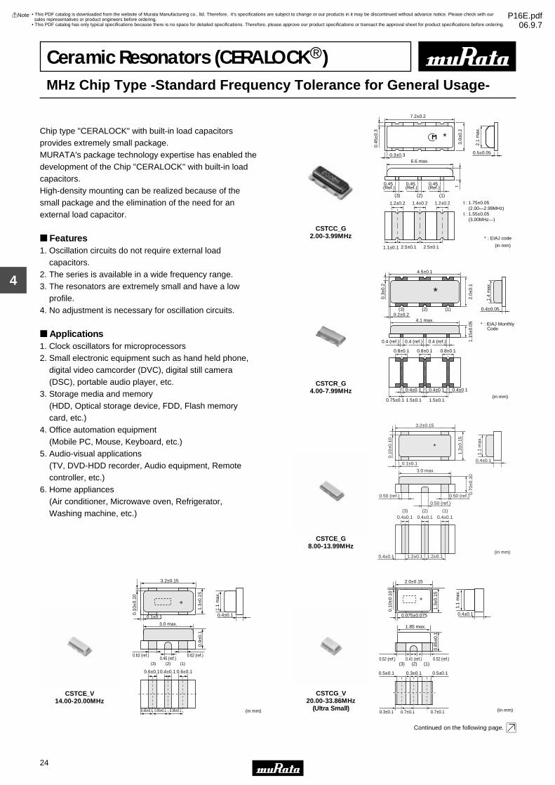
Chip type "CERALOCK" with built-in load capacitors provides extremely small package.MURATA's package technology expertise has enabled the development of the Chip "CERALOCK" with built-in load capacitors.High-density mounting can be realized because of the small package and the elimination of the need for an external load capacitor.
Features1. Oscillation circuits do not require external load capacitors.2. The series is available in a wide frequency range.3. The resonators are extremely small and have a low profile.4. No adjustment is necessary for oscillation circuits.
Applications1. Clock oscillators for microprocessors2. Small electronic equipment such as hand held phone, digital video camcorder (DVC), digital still camera (DSC), portable audio player, etc.3. Storage media and memory (HDD, Optical storage device, FDD, Flash memory card, etc.)4. Office automation equipment (Mobile PC, Mouse, Keyboard, etc.)5. Audio-visual applications (TV, DVD-HDD recorder, Audio equipment, Remote controller, etc.)6. Home appliances (Air conditioner, Microwave oven, Refrigerator, Washing machine, etc.)
0.45 (Ref.)
1.2±0.2
6.6 max.
(3) (2) (1)
0.3±0.3 0.5±0.05
2.5±0.1 2.5±0.11.1±0.1
7.2±0.2
3.0±
0.2
t
0.45
±0.3
∗
∗ : EIAJ code
t : 1.75±0.05 (2.00—2.99MHz)t : 1.55±0.05 (3.00MHz—)
1.4±0.2 1.2±0.2
0.45 (Ref.)
0.45 (Ref.)
2.1
max
.
(in mm)
CSTCC_G2.00-3.99MHz
4.5±0.1
∗
4.1 max.
0.8±0.1
0.75±0.1 1.5±0.1 1.5±0.1
0.4±0.1 0.4±0.1 0.4±0.1
0.8±0.1 0.8±0.1
0.4 (ref.)0.4 (ref.)0.4 (ref.)
0.4±0.050.2±0.2
0.3±
0.2
2.0±
0.1
1.4
max
.
(2) (1)(3)
1.15
±0.0
5 ∗ : EIAJ Monthly Code
(in mm)
CSTCR_G4.00-7.99MHz
3.2±0.15
1.3±
0.15
0.50 (ref.)
0.50 (ref.)
0.50 (ref.)
3.0 max.
0.10
±0.1
0
0.4±0.1
0.4±0.1 1.2±0.1 1.2±0.1
(1)(2)(3)
0.1±0.1
1.1
max
.
0.4±0.1
0.70
±0.1
0
0.4±0.1 0.4±0.1
(in mm)
∗
CSTCE_G8.00-13.99MHz
3.2±0.15
0.10
±0.1
0
0.1±0.1
1.3±
0.15
1.1
max
.
0.4±0.1
0.62 (ref.) 0.62 (ref.)
0.9±
0.1
3.0 max.
0.6±0.10.4±0.1 0.6±0.1
(1)(2)(3)
0.65±0.1 0.95±0.1 0.95±0.1
0.45 (ref.)
(in mm)
CSTCE_V14.00-20.00MHz
0.52 (ref.) 0.41 (ref.) 0.52 (ref.)
2.0±0.15
1.3±
0.15
0.85
±0.1
1.1
max
.
0.10
±0.1
0
0.075±0.075 0.4±0.1
1.85 max.
0.5±0.1
0.3±0.1 0.7±0.1 0.7±0.1
0.3±0.1 0.5±0.1
(1)(2)(3)
(in mm)
CSTCG_V20.00-33.86MHz
(Ultra Small)
Continued on the following page.
• This PDF catalog is downloaded from the website of Murata Manufacturing co., ltd. Therefore, it’s specifications are subject to change or our products in it may be discontinued without advance notice. Please check with our sales representatives or product engineers before ordering.
• This PDF catalog has only typical specifications because there is no space for detailed specifications. Therefore, please approve our product specifications or transact the approval sheet for product specifications before ordering.
!Note P16E.pdf06.9.7
25
4
!Note • Please read rating and !CAUTION (for storage, operating, rating, soldering, mounting and handling) in this catalog to prevent smoking and/or burning, etc.• This catalog has only typical specifications because there is no space for detailed specifications. Therefore, please approve our product specifications or transact the approval sheet for product specifications before ordering.
Continued from the preceding page.
2.5T0.2 1.2 max.
Thickness varieswith frequency.*: EIAJ code
0.5T0.2 0.5T0.2
1.0T0.21.0T0.21.25T0.2
(0.5) (0.5)0.05+0.10
-0.050.05+0.10-0.05
0.4 +0.3-0.20.4 +0.3
-0.2
*
2.0T
0.2
(in mm)
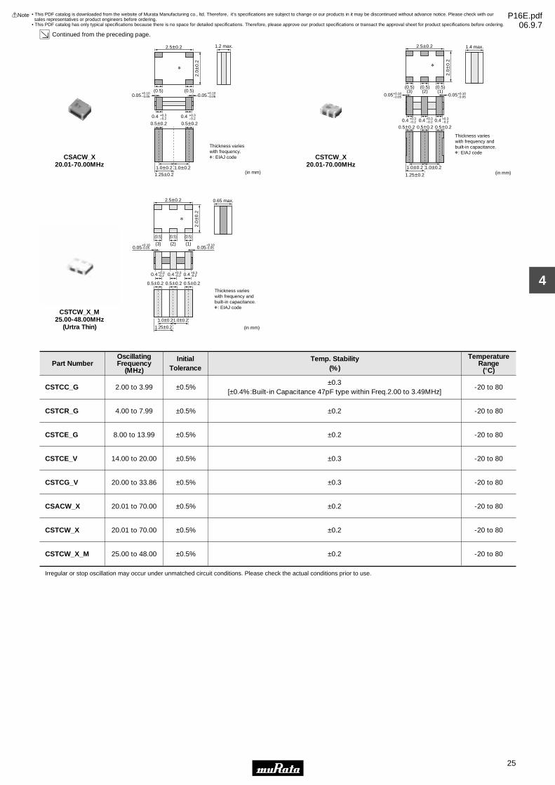
CSACW_X20.01-70.00MHz
2.5T0.2 1.4 max.
Thickness varieswith frequency and built-in capacitance.*: EIAJ code
0.5T0.2 0.5T0.20.5T0.2
1.0T0.21.0T0.2
1.25T0.2
(0.5)(3)
(0.5)(1)
(0.5)(2)
0.05+0.10-0.05 0.05+0.10
-0.05
0.4 +0.3-0.20.4 +0.3
-0.20.4 +0.3-0.2
*
2.0T
0.2
(in mm)
CSTCW_X20.01-70.00MHz
2.5T0.2 0.65 max.
0.5T0.2 0.5T0.20.5T0.2
1.0T0.21.0T0.2
1.25T0.2
(0.5) (0.5)(0.5)
(3) (1)(2)0.05
+0.10-0.05 0.05
+0.10-0.05
*
2.0T
0.2
(in mm)
0.4 +0.3-0.20.4 +0.3
-0.20.4 +0.3-0.2
Thickness varieswith frequency and built-in capacitance.*: EIAJ code
CSTCW_X_M25.00-48.00MHz
(Urtra Thin)
Part NumberOscillatingFrequency
(MHz)
InitialTolerance
Temp. Stability(%)
TemperatureRange
(°C)
CSTCC_G 2.00 to 3.99 ±0.5%±0.3
[±0.4%:Built-in Capacitance 47pF type within Freq.2.00 to 3.49MHz]-20 to 80
CSTCR_G 4.00 to 7.99 ±0.5% ±0.2 -20 to 80
CSTCE_G 8.00 to 13.99 ±0.5% ±0.2 -20 to 80
CSTCE_V 14.00 to 20.00 ±0.5% ±0.3 -20 to 80
CSTCG_V 20.00 to 33.86 ±0.5% ±0.3 -20 to 80
CSACW_X 20.01 to 70.00 ±0.5% ±0.2 -20 to 80
CSTCW_X 20.01 to 70.00 ±0.5% ±0.2 -20 to 80
CSTCW_X_M 25.00 to 48.00 ±0.5% ±0.2 -20 to 80
Irregular or stop oscillation may occur under unmatched circuit conditions. Please check the actual conditions prior to use.
• This PDF catalog is downloaded from the website of Murata Manufacturing co., ltd. Therefore, it’s specifications are subject to change or our products in it may be discontinued without advance notice. Please check with our sales representatives or product engineers before ordering.
• This PDF catalog has only typical specifications because there is no space for detailed specifications. Therefore, please approve our product specifications or transact the approval sheet for product specifications before ordering.
!Note P16E.pdf06.9.7

26
4
!Note • Please read rating and !CAUTION (for storage, operating, rating, soldering, mounting and handling) in this catalog to prevent smoking and/or burning, etc.• This catalog has only typical specifications because there is no space for detailed specifications. Therefore, please approve our product specifications or transact the approval sheet for product specifications before ordering.
Oscillation Frequency Measuring CircuitCSTCR_G/CSTCE_G/CSTCE_V/CSTCG_V
VDD
RfTo Frequency Counter
5pF
1MΩ
Rd
C1 C2
(1) (3)
(2)
CSTCC_G/CSTCW_X
Rf
Rd
VDD
C1 C2
To Frequency counter
(1) (3)
(2)
CSACW_X
Rf
Rd
VDD
CL2CL1
To Frequency counter
CSTCW_X_M
Rf
VDD
C1 C2
To Frequency Counter
(1) (3)
(2)
• This PDF catalog is downloaded from the website of Murata Manufacturing co., ltd. Therefore, it’s specifications are subject to change or our products in it may be discontinued without advance notice. Please check with our sales representatives or product engineers before ordering.
• This PDF catalog has only typical specifications because there is no space for detailed specifications. Therefore, please approve our product specifications or transact the approval sheet for product specifications before ordering.
!Note P16E.pdf06.9.7

27
4
!Note • Please read rating and !CAUTION (for storage, operating, rating, soldering, mounting and handling) in this catalog to prevent smoking and/or burning, etc.• This catalog has only typical specifications because there is no space for detailed specifications. Therefore, please approve our product specifications or transact the approval sheet for product specifications before ordering.
Standard Land Pattern DimensionsCSTCC_G
3.8~
4.4
1.2 1.2
2.5 2.5
1.4 1.2 1.2
Land Pattern
(in mm)
CSTCR_G
2.6
1.6
0.8
0.4
1.5 1.5
0.4 0.4
0.8 0.80.70.7
Land Pattern
(in mm)
CSTCE_G
0.4
1.90
~ 2
.10
0.4 0.40.8
Land Pattern
0.8
1.2 1.2
(in mm)
CSTCE_V
Land Pattem
0.3 0.30.65 0.30.65
0.95 0.95
1.6
(in mm)
CSTCG_V
Land Pattem
0.3 0.30.5 0.30.5
0.8 0.8
1.6
(in mm)
CSACW_X
0.5 0.5
2.0
0.8
0.8
2.0T
0.2
0.3
0.3
Land Pattern
(in mm)
CSTCW_X
0.5 0.50.50.5
1.0 1.0
0.8
0.8
2.0T
0.2
0.3
0.3
0.5
Land Pattern
(in mm)
CSTCW_X_M
0.5 0.50.50.5
1.0 1.0
0.8
0.8
2.0
0.3
0.3
0.5
Land Pattern
(in mm)
• This PDF catalog is downloaded from the website of Murata Manufacturing co., ltd. Therefore, it’s specifications are subject to change or our products in it may be discontinued without advance notice. Please check with our sales representatives or product engineers before ordering.
• This PDF catalog has only typical specifications because there is no space for detailed specifications. Therefore, please approve our product specifications or transact the approval sheet for product specifications before ordering.
!Note P16E.pdf06.9.7

28
4
!Note • Please read rating and !CAUTION (for storage, operating, rating, soldering, mounting and handling) in this catalog to prevent smoking and/or burning, etc.• This catalog has only typical specifications because there is no space for detailed specifications. Therefore, please approve our product specifications or transact the approval sheet for product specifications before ordering.
Oscillation Frequency Temperature StabilityCSTCC_G
Osc
illat
ing
Fre
quen
cy S
hift
(%)
Temperature (°C)
-40 -20 0 +20 +40 +60 +80 +100
+0.2
+0.1
0
-0.1
-0.2
CSTCR_G
-60 -40 -20 0 +20 +40 +60 +80 +100 +120 +140
Osc
illat
ing
Fre
quen
cy S
hift
(%)
+0.2
+0.1
0
-0.1
-0.2
Temperature (°C)
CSTCE_G
-60 -40 -20 0 +20 +40 +60 +80 +100 +120 +140
Osc
illat
ing
Fre
quen
cy S
hift
(%)
Temperature (°C)
+0.2
+0.1
0
-0.1
-0.2
CSTCE_V
-60 -40 -20 0 +20 +40 +60 +80 +100 +120 +140
Osc
illat
ing
Fre
quen
cy S
hift
(%)
+0.2
+0.1
0
-0.1
-0.2
Temperature (°C)
CSTCG_V
-60 -40 -20 0 +20 +40 +60 +80 +100 +120 +140
Osc
illat
ing
Fre
quen
cy S
hift
(%)
Temperature (°C)
+0.2
+0.1
0
-0.1
-0.2
CSACW_X
Osc
illat
ing
Fre
quen
cy S
hift
(%)
Temperature (°C)
-40 -20 0 +20 +40 +60 +80 +100
+0.2
+0.1
0
-0.1
-0.2
CSTCW_X
Osc
illat
ing
Fre
quen
cy S
hift
(%)
Temperature (°C)
-40 -20 0 +20 +40 +60 +80 +100
+0.2
+0.1
0
-0.1
-0.2
CSTCW_X_M
Osc
illat
ing
Fre
quen
cy S
hift
(%)
Temperature (°C)
-40 -20 0 +20 +40 +60 +80 +100
+0.2
+0.1
0
-0.1
-0.2
• This PDF catalog is downloaded from the website of Murata Manufacturing co., ltd. Therefore, it’s specifications are subject to change or our products in it may be discontinued without advance notice. Please check with our sales representatives or product engineers before ordering.
• This PDF catalog has only typical specifications because there is no space for detailed specifications. Therefore, please approve our product specifications or transact the approval sheet for product specifications before ordering.
!Note P16E.pdf06.9.7

Application Circuits Utilization
29
4
!Note • Please read rating and !CAUTION (for storage, operating, rating, soldering, mounting and handling) in this catalog to prevent smoking and/or burning, etc.• This catalog has only typical specifications because there is no space for detailed specifications. Therefore, please approve our product specifications or transact the approval sheet for product specifications before ordering.
uPD78F0533GB (NEC Electronics)8-bit Microcomputer
H 6
11 10 L120.1µF
IC : µPD78F0533GB
Vdd=5.0V
10kΩ
H: 15, 16, 47L: 9, 13, 14, 48
CERALOCKr
C1 C2CERALOCKr: CSTCR4M00G55-R0
C1=39pF (Typ.)C2=39pF (Typ.)
V2V1
M38235G6HP (Renesas)8-bit Microcomputer
H 25
28 29 L
M38235G6HP
Vcc=5.0V
H: 71L: 30, 73
CERALOCKr
C1 C2CERALOCKr: CSTLS8M00G53-B0
C1=15pF (Typ.)C2=15pF (Typ.)
V2V1
TMP19A43FDXBG (Toshiba)32-bit Microcomputer
A14 A15 GND
EVALUATION BOARDIC : TMP19A43FDXBG
Vcc=1.5V
Xin: A14Xout: A15
CERALOCKr
C1 C2CERALOCKr: CSTCE10M0G52-R0
C1=10pF (Typ.)C2=10pF (Typ.)
Vcc'=2.5V Vcc''=3.3V
V2V1
MN103SFC2D (Panasonic)32-bit Microcomputer
H
14 13 LVdd210µF
IC : MN103SFC2D
Vdd=5.0V
H: 9, 17, 34L: 7, 15, 36Vdd2: 16, 38
CERALOCKr
C1 C2CERALOCKr: CSTCR5M00G55Z-R0
C1=39pF (Typ.)C2=39pF (Typ.)
V2V1
MB95F128H (Fujitsu)8-bit Microcomputer
H
56 55 L
IC : MB95F128H
Vcc=5.0V
H: 3, 28, 51, 79L: 4, 29, 54, 57
CERALOCKr
C1 C2CERALOCKr: CSTCE8M00G52-R0
C1=10pF (Typ.)C2=10pF (Typ.)
V2V1
PIC16F716-I/SO (Microchip)8-bit Microcomputer
H
16 15 GND
EVALUATION BOARDIC : PIC16F716-I/SO(HS)
Vdd=5.0V
CERALOCKr
C1 C2 CERALOCKr: CSTCE12M0G52A-R0C1=10pF (Typ.)C2=10pF (Typ.)
V2V1
1MΩ
Continued on the following page.
• This PDF catalog is downloaded from the website of Murata Manufacturing co., ltd. Therefore, it’s specifications are subject to change or our products in it may be discontinued without advance notice. Please check with our sales representatives or product engineers before ordering.
• This PDF catalog has only typical specifications because there is no space for detailed specifications. Therefore, please approve our product specifications or transact the approval sheet for product specifications before ordering.
!Note P16E.pdf06.9.7

Application Circuits Utilization
30
4
!Note • Please read rating and !CAUTION (for storage, operating, rating, soldering, mounting and handling) in this catalog to prevent smoking and/or burning, etc.• This catalog has only typical specifications because there is no space for detailed specifications. Therefore, please approve our product specifications or transact the approval sheet for product specifications before ordering.
Continued from the preceding page.
HD64F36077GH (Renesas)16-bit Microcomputer
H
11 10 L60.1µF
IC : HD64F36077GH
Vcc=5.0V
H: 3, 7, 12L: 8, 9
CERALOCKr
C1 C2CERALOCKr: CSTCE8M00G52-R0
C1=10pF (Typ.)C2=10pF (Typ.)
V2V1
LC87F5G32A (Sanyo)8-bit Microcomputer
26 H' H 2
6 7 LL'
10kF2.2kF
IC : LC87F5G32A
Vdd=5.0V
10kΩ 10kΩ 100pF
47000pF510Ω
H: 8, 19, 39L: 5, 20, 40H': 29, 31, 35L': 30, 32~34, 36
CERALOCKr
C1 C2 CERALOCKr: CSTLS5M00G53-B0C1=15pF (Typ.)C2=15pF (Typ.)
V2V1
uPD70F3215HYGC (NEC Electronics)32-bit Microcomputer
H 14
12 13 L10
IC : µPD70F3215HYGC
Vdd=5.0V
H: 1, 5, 9, 34, 70L: 2, 8, 11, 33, 69
CERALOCKr
C1 C2CERALOCKr: CSTCR5M00G55-R0
C1=39pF (Typ.)C2=39pF (Typ.)
V2V1
10µF
ATmega128 (Atmel)8-bit Microcomputer
H
24 23 L
IC : ATmega128
Vcc=5.0V
H: 21, 52, 64L: 22, 53, 63
CERALOCKr
C1 C2CERALOCKr: CSTCE8M00G52-R0
C1=10pF (Typ.)C2=10pF (Typ.)
V2V1
ST7FLITE29F2B6 (ST Microelectronics)8-bit Microcomputer
H 18
15 14 L
IC : ST7FLITE29F2B6
Vdd=5.0V
H: 17L: 16
CERALOCKr
C1 C2CERALOCKr: CSTCE16M0V53-R0
C1=15pF (Typ.)C2=15pF (Typ.)
V2V1
TMS320F2810PBKA (Texas Insturumets)32-bit Microcomputer
58 57 L
IC : TMS320F2810PBKA
Vdd1=1.8V
CERALOCKr: CSTCE15M0V53-R0C1=15pF (Typ.)C2=15pF (Typ.)
Vdd2=3.3V
H1 H2
V2V1
100ΩCERALOCKr
C1 C2
H1: 20, 29, 42, 56, 63, 74, 82, 94, 99, 100, 102, 110, 114H2: 1, 13, 14, 25, 49, 52, 83, 104, 118L: 12, 15, 17, 26, 30, 39, 53, 59, 62, 73, 88, 95, 103, 109, 115, 117, 128
• This PDF catalog is downloaded from the website of Murata Manufacturing co., ltd. Therefore, it’s specifications are subject to change or our products in it may be discontinued without advance notice. Please check with our sales representatives or product engineers before ordering.
• This PDF catalog has only typical specifications because there is no space for detailed specifications. Therefore, please approve our product specifications or transact the approval sheet for product specifications before ordering.
!Note P16E.pdf06.9.7

31
5
!Note • Please read rating and !CAUTION (for storage, operating, rating, soldering, mounting and handling) in this catalog to prevent smoking and/or burning, etc.• This catalog has only typical specifications because there is no space for detailed specifications. Therefore, please approve our product specifications or transact the approval sheet for product specifications before ordering.
Ceramic Resonators (CERALOCKr)MHz Lead Type -Standard Frequency Tolerance for General Usage-
MURATA's ceramic resonator, "CERALOCK" with built-in load capacitors, has been widely applied as the most suitable component for clock oscillators in a broad range of microprocessors.The CSTLS series can be used in the design of oscillation circuits not requiring external load capacitors, enabling both high-density mounting and cost reduction.
Features1. Oscillation circuits do not require external load capacitors. There is some variation in built-in capacitance values applicable to various IC (except for CSALS series).2. The series is stable over a wide temperature range.3. The resonators are compact, lightweight and exhibit superior shock resistance performance.4. They enable the design of oscillator circuits requiring no adjustment.5. The series is inexpensive and available in stable supply.
Applications1. DTMF generators2. Clock oscillators for microcomputers3. Remote control units4. Automated office equipment
∗∗∗
∗∗∗ : Weekly Date Code(in mm)
8.0±1.0 3.0±1.0
5.5±
0.5
3.5±
0.3
ø0.
48±0
.05
2.5±0.22.5±0.2
0.7
(Ref
.)
0.7 (Ref.)0.7 (Ref.)7.0 (Ref.)(3) (2) (1)
CSTLS_G3.40-10.00MHz
∗
5.5±1.0
2.5±0.2 2.5±0.2
(in mm)
6.5±
0.5
3.5±
0.3
φ0.4
8±0.
05
T ∗1
T ∗1
(3) (2) (1)
: 3.5±1.0 (16.00—32.99MHz) 3.0±1.0 (33.00—70.00MHz)
∗ : EIAJ Monthly Code
CSTLS_X16.00-70.00MHz
∗
5.5±1.0 T∗1
T : 3.5±1.0 (16.00—32.99MHz) 3.0±1.0 (33.00—70.00MHz)
∗1
5.0±0.3
6.5±
0.5
3.5±
0.3
φ0.4
8±0.
05
(in mm)
∗ : EIAJ Monthly CodeCSALS_X
16.00-70.00MHz
Part NumberOscillatingFrequency
(MHz)
InitialTolerance
Temp. Stability(%)
TemperatureRange
(°C)
CSTLS_G 3.40 to 10.00 ±0.5%±0.2
[-0.4% to +0.2%:Built-in Capacitance 47pF type]-20 to 80
CSTLS_X 16.00 to 70.00 ±0.5% ±0.2 -20 to 80
CSALS_X 16.00 to 70.00 ±0.5% ±0.2 -20 to 80
Irregular or stop oscillation may occur under unmatched circuit conditions. Please check the actual conditions prior to use.
The order quantity should be an integral multiple of the "Minimum Quantity" shown in the packaging page.
• This PDF catalog is downloaded from the website of Murata Manufacturing co., ltd. Therefore, it’s specifications are subject to change or our products in it may be discontinued without advance notice. Please check with our sales representatives or product engineers before ordering.
• This PDF catalog has only typical specifications because there is no space for detailed specifications. Therefore, please approve our product specifications or transact the approval sheet for product specifications before ordering.
!Note P16E.pdf06.9.7

32
5
!Note • Please read rating and !CAUTION (for storage, operating, rating, soldering, mounting and handling) in this catalog to prevent smoking and/or burning, etc.• This catalog has only typical specifications because there is no space for detailed specifications. Therefore, please approve our product specifications or transact the approval sheet for product specifications before ordering.
Oscillation Frequency Measuring CircuitCSTLS_G/CSTLS_X
Rf
Rd
VDD
C1 C2
To Frequency counter
(1) (3)
(2)
CSALS_X
Rf
Rd
VDD
CL2CL1
To Frequency counter
Oscillation Frequency Temperature StabilityCSTLS_G
Osc
illat
ing
Fre
quen
cy S
hift
(%)
Temperature (°C)
Y40
W0.50
W0.25
0
Y0.25
Y0.50
0 40 80 120
CSTLS_X
Temperature (˚C)
Osc
illat
ing
Fre
quen
cy S
hift
(%)
0.3
0.2
0.1
0.0
−0.1
−0.2
−0.3
−50 −30 −10 10 30 50 70 90 110 130
CSALS_X
Temperature (˚C)
Osc
illat
ing
Fre
quen
cy S
hift
(%)
0.3
0.2
0.1
0.0
−0.1
−0.2
−0.3
−50 −30 −10 10 30 50 70 90 110 130
• This PDF catalog is downloaded from the website of Murata Manufacturing co., ltd. Therefore, it’s specifications are subject to change or our products in it may be discontinued without advance notice. Please check with our sales representatives or product engineers before ordering.
• This PDF catalog has only typical specifications because there is no space for detailed specifications. Therefore, please approve our product specifications or transact the approval sheet for product specifications before ordering.
!Note P16E.pdf06.9.7

33
6
!Note • Please read rating and !CAUTION (for storage, operating, rating, soldering, mounting and handling) in this catalog to prevent smoking and/or burning, etc.• This catalog has only typical specifications because there is no space for detailed specifications. Therefore, please approve our product specifications or transact the approval sheet for product specifications before ordering.
Ceramic Resonators (CERALOCKr)kHz Chip Type -Standard Frequency Tolerance for General Usage-
MURATA's original package technologies have enabled the development of the kHz band "CERALOCK".The series is perfect in miniature remote control units and AV modules."CERALOCK" can be reflow soldered and mounted by automatic placers.
Features1. The series withstands reflow soldering.2. The series is mountable by automatic placers.3. No adjustment is necessary for oscillation circuits.
Applications1. Clock oscillators for microprocessors2. OA equipment3. AV modules
7.5±0.3
1.1±0.1
0.9±0.1
3.3±0.3
0.15±0.05
1.0
max
.
0.15
max
.
2.0±
0.58.5±
0.3
1.0±
0.5
5.0±0.2
0+0.1-0.4
∗ : EIAJ code
(in mm)CSBFB_J430-519kHz
5.0±0.3
0.8±0.2
0.7±0.2
2.5±0.2
2.3±0.2
0.15±0.05
0.10±0.03
1.0
max
. 6.0±
0.3
2.0±
0.5
1.0±
0.3
0.15
max
.
0+0.1−0.4
∗ : EIAJ code
(in mm)
CSBFB_J700-1250kHz
Part NumberOscillating Frequency
(kHz)Initial Tolerance
Temp. Stability(%)
Temperature Range(°C)
CSBFB_J 430 to 519, 700 to 1250 - ±0.3 -20 to 80
Irregular or stop oscillation may occur under unmatched circuit conditions. Please check the actual conditions prior to use.
Oscillation Frequency Measuring Circuit
Rf
Rd
VDD
CL2CL1
To Frequency counter
Oscillation Frequency Temperature Stability
Y40 8040 120
W0.5
0
Y0.5
Temperature (˚C)
0
Osc
illat
ing
Fre
quen
cy S
hift
(%)
Continued on the following page.
• This PDF catalog is downloaded from the website of Murata Manufacturing co., ltd. Therefore, it’s specifications are subject to change or our products in it may be discontinued without advance notice. Please check with our sales representatives or product engineers before ordering.
• This PDF catalog has only typical specifications because there is no space for detailed specifications. Therefore, please approve our product specifications or transact the approval sheet for product specifications before ordering.
!Note P16E.pdf06.9.7

34
6
!Note • Please read rating and !CAUTION (for storage, operating, rating, soldering, mounting and handling) in this catalog to prevent smoking and/or burning, etc.• This catalog has only typical specifications because there is no space for detailed specifications. Therefore, please approve our product specifications or transact the approval sheet for product specifications before ordering.
Continued from the preceding page.
Standard Land Pattern DimensionsCSBFB_J (430-519kHz)
3.3
1.7 1.7
2.0
0.5
(in mm)
CSBFB_J (700-1250kHz)
1.0
1.5 1.5
3.0
0.5
(in mm)
• This PDF catalog is downloaded from the website of Murata Manufacturing co., ltd. Therefore, it’s specifications are subject to change or our products in it may be discontinued without advance notice. Please check with our sales representatives or product engineers before ordering.
• This PDF catalog has only typical specifications because there is no space for detailed specifications. Therefore, please approve our product specifications or transact the approval sheet for product specifications before ordering.
!Note P16E.pdf06.9.7

35
7
!Note • Please read rating and !CAUTION (for storage, operating, rating, soldering, mounting and handling) in this catalog to prevent smoking and/or burning, etc.• This catalog has only typical specifications because there is no space for detailed specifications. Therefore, please approve our product specifications or transact the approval sheet for product specifications before ordering.
Ceramic Resonators (CERALOCKr)kHz Lead Type -Standard Frequency Tolerance for General Usage-
The CSBLA series ceramic resonators owe their development to MURATA's innovative expert technologiesand the application of mass production techniques typically utilized in the manufacture of piezoelectricceramic components. Because of their high mechanical Qand consistent high quality, the CSBLA series are ideally suited to microprocessor and remote control unit applications.
Features1. The series is stable over a wide temperature range and with respect to long-term aging.2. The series comprises fixed, tuned, solid-state devices.3. The resonators are miniature and lightweight.4. They exhibit excellent shock resistance performance.5. Oscillating circuits requiring no adjustment can be designed by utilizing these resonators in conjunction with transistors or appropriate ICs.
Applications1. Square-wave and sine-wave oscillators2. Clock generator for microprocessors3. Remote control systems
7.9±0.3 3.6±0.3
0.8±0.11.1±0.1
5.0±0.2 1.8±
0.3
0.1±
0.03
0.25
±0.1
4.3±
0.5
9.3±
0.3
1.5
max
.
∗ : EIAJ code
(in mm)
CSBLA_E375-429kHz
7.0±0.3 3.5±0.3
0.8±0.11.1±0.1
5.0±0.2
1.75
±0.5
3.5±
0.5
9.0±
0.3
0.1±
0.03
0.25
±0.1
1.5
max
.
∗ : EIAJ code(in mm)
CSBLA_E430-509kHz
7.0±0.3 3.5±0.3
0.8±0.11.1±0.1
5.0±0.2
1.75
±0.5
3.5±
0.5
9.0±
0.3
0.1±
0.03
0.25
±0.1
1.5
max
.
∗ : EIAJ code
(in mm)
CSBLA_E510-699kHz
1.5
max
.
5.0±0.3 2.2±0.2
6.0±
0.3
3.5±
.0.5
0.8±0.2
2.5±0.2 1.1±
0.2
0.6±0.2
0.15±0.05
0.1±0.03
∗ : EIAJ code
in mm
CSBLA_J700-1250kHz
Part NumberOscillating Frequency
(kHz)Initial Tolerance
Temp. Stability(%)
Temperature Range(°C)
CSBLA_E 375 to 699 - ±0.3 -20 to +80
CSBLA_J 700 to 1250 - ±0.3 -20 to 80
Irregular or stop oscillation may occur under unmatched circuit conditions. Please check the actual conditions prior to use.
The order quantity should be an integral multiple of the "Minimum Quantity" shown in the packaging page.
• This PDF catalog is downloaded from the website of Murata Manufacturing co., ltd. Therefore, it’s specifications are subject to change or our products in it may be discontinued without advance notice. Please check with our sales representatives or product engineers before ordering.
• This PDF catalog has only typical specifications because there is no space for detailed specifications. Therefore, please approve our product specifications or transact the approval sheet for product specifications before ordering.
!Note P16E.pdf06.9.7

36
7
!Note • Please read rating and !CAUTION (for storage, operating, rating, soldering, mounting and handling) in this catalog to prevent smoking and/or burning, etc.• This catalog has only typical specifications because there is no space for detailed specifications. Therefore, please approve our product specifications or transact the approval sheet for product specifications before ordering.
Oscillation Frequency Measuring Circuit
Rf
Rd
VDD
CL2CL1
To Frequency counter
Oscillation Frequency Temperature Stability
Y40 8040 120
W0.5
0
Y0.5
Temperature (˚C)
0
Osc
illat
ing
Fre
quen
cy S
hift
(%)
• This PDF catalog is downloaded from the website of Murata Manufacturing co., ltd. Therefore, it’s specifications are subject to change or our products in it may be discontinued without advance notice. Please check with our sales representatives or product engineers before ordering.
• This PDF catalog has only typical specifications because there is no space for detailed specifications. Therefore, please approve our product specifications or transact the approval sheet for product specifications before ordering.
!Note P16E.pdf06.9.7

One heat stress, shown in the profile at right, is applied to resonator; then, after being placed in natural conditions for 1 hour, the resonator is measured. (a) Pre-heating conditions should be +150 to +180°C for
60 to 120 seconds. Ascending time up to +150°C should be longer than 30 seconds.
(b) Heating conditions should be within 40 seconds at +230°C min., but peak temperature should be Iower than +260°C.
1. Soldering Conditions (1) Reflow
HCFC, Isopropanol, Tap water, Demineralized water, Cleanthrough750H, Pine alpha 100S, Techno care FRW
Some series do not withstand washing.Please check the list at right before use.
2. Wash
3. Notice for Mounting
(1) Cleaning Solvents
dT<=60°C (dT=Component-solvent) *1 ex. In case the component at +90°C immerses into cleaning solvent at +60°C, then dT=30°C.
(2) Temperature Difference : dT *1
5 minutes max. by air blow at +80°C max. (4) Drying
(a) Total washing time should be within 10 minutes. (b) The component may be damaged if it is washed with
chlorine, petroleum, or alkali cleaning solvent.
(a) The component is recommended for use with placement machines which employ optical placement capabilities. The component might be damaged by excessive mechanical force. Please make sure to evaluate by using placement machines before going into mass production. Do not use placement machines which utilize mechanical positioning. Please contact Murata for details beforehand.
(b) Please insure the component is thoroughly evaluated in your application circuit.
(c) Please do not apply excess mechanical stress to the component and terminals during soldering.
(5) Others
(a) Ultrasonic Wash 1 minute max. in above solvent at +60°C max. (Frequency: 28kHz, Output: 20W/L)
(b) Immersion Wash 5 minutes max. in above solvent at +60°C max.
(c) Shower or Rinse Wash 5 minutes max. in above solvent at +60°C max.
(3) Conditions
Soldering iron of +300±5°C should be placed 0.5mm above electrode of resonator. Melting solder through soldering iron should be applied to electrode for 3±1 seconds; then, after being placed in natural conditions for 24 hours, the resonator should be measured.
(2) Soldering Iron
CSTCC (Except 2.00 - 3.49MHz)
CSTCC (Only 2.00 - 3.49MHz)
Series Wash
Available
Not Available
150
230
180
30 sec.min.
40 sec.max.
Peak(260˚C max.)
Pre-heating(150-180˚C)
Heating(230˚C)
GradualCooling
120 sec.min.
60-120 sec.
Tem
pera
ture
(˚C
)
CSTCC Series
MHz Chip Type Notice (Soldering and Mounting) for General Usage
37
7
!Note • Please read rating and !CAUTION (for storage, operating, rating, soldering, mounting and handling) in this catalog to prevent smoking and/or burning, etc.• This catalog has only typical specifications because there is no space for detailed specifications. Therefore, please approve our product specifications or transact the approval sheet for product specifications before ordering.
• This PDF catalog is downloaded from the website of Murata Manufacturing co., ltd. Therefore, it’s specifications are subject to change or our products in it may be discontinued without advance notice. Please check with our sales representatives or product engineers before ordering.
• This PDF catalog has only typical specifications because there is no space for detailed specifications. Therefore, please approve our product specifications or transact the approval sheet for product specifications before ordering.
!Note P16E.pdf06.9.7

One heat stress, shown in the profile at right, is applied to resonator; then, after being placed in natural conditions for 1 hour, the resonator is measured. (a) Pre-heating conditions should be +150 to +180°C for
60 to 120 seconds. Ascending time up to +150°C should be longer than 30 seconds.
(b) Heating conditions should be within 40 seconds at +230°C min., but peak temperature should be Iower than +260°C.
1. Soldering Conditions (1) Reflow
Please contact us in case you need washable component.2. Wash (Automotive types)
3. Notice for Mounting(a) The component is recommended for use with
placement machines which employ optical placement capabilities. The component might be damaged by excessive mechanical force. Please make sure to evaluate by using placement machines before going into mass production. Do not use placement machines which utilize mechanical positioning. Please contact Murata for details beforehand.
(b) Please insure the component is thoroughly evaluated in your application circuit.
(c) Please do not apply excess mechanical stress to the component and terminals during soldering.
Soldering iron of +350±5°C should be placed 0.5mm above electrode of resonator. Melting solder through soldering iron should be applied to electrode for 3±1 seconds; then, after being placed in natural conditions for 24 hours, the resonator should be measured.
(2) Soldering Iron
150
230
180
30 sec.min.
40 sec.max.
Peak(260˚C max.)
Pre-heating(150-180˚C)
Heating(230˚C)
GradualCooling
120 sec.min.
60-120 sec.
Tem
pera
ture
(˚C
)
CSTCR/CSTCE_V/CSTCG Series
MHz Chip Type Notice (Soldering and Mounting) for General Usage
38
7
!Note • Please read rating and !CAUTION (for storage, operating, rating, soldering, mounting and handling) in this catalog to prevent smoking and/or burning, etc.• This catalog has only typical specifications because there is no space for detailed specifications. Therefore, please approve our product specifications or transact the approval sheet for product specifications before ordering.
• This PDF catalog is downloaded from the website of Murata Manufacturing co., ltd. Therefore, it’s specifications are subject to change or our products in it may be discontinued without advance notice. Please check with our sales representatives or product engineers before ordering.
• This PDF catalog has only typical specifications because there is no space for detailed specifications. Therefore, please approve our product specifications or transact the approval sheet for product specifications before ordering.
!Note P16E.pdf06.9.7

One heat stress, shown in the profile at right, is applied to resonator; then, after being placed in natural conditions for 1 hour, the resonator is measured. (a) Pre-heating conditions should be +150 to +180°C for
60 to 120 seconds. Ascending time up to +150°C should be longer than 30 seconds.
(b) Heating conditions should be within 40 seconds at +230°C min., but peak temperature should be Iower than +260°C.
1. Soldering Conditions (1) Reflow
Please contact us in case you need washable component.2. Wash (Automotive types)
3. Notice for Mounting(a) The component is recommended for use with
placement machines which employ optical placement capabilities. The component might be damage by excessive mechanical force. Please make sure to evaluate by using placement machines before going into mass production. Do not use placement machines which utilize mechanical positioning. Please contact Murata for details beforehand.
(b) Please insure the component is thoroughly evaluated in your application circuit.
(c) Please do not apply excess mechanical stress to the component and terminals during soldering.
Soldering iron of +330±5°C should be placed 0.5mm above electrode of resonator. Melting solder through soldering iron should be applied to electrode for 3±1 seconds; then, after being placed in natural conditions for 24 hours, the resonator should be measured.
(2) Soldering Iron
150
230
180
30 sec.min.
40 sec.max.
Peak(260˚C max.)
Pre-heating(150-180˚C)
Heating(230˚C)
GradualCooling
120 sec.min.
60-120 sec.
Tem
pera
ture
(˚C
)
CSTCE_G/CSTCE_XK Series
MHz Chip Type Notice (Soldering and Mounting) for General Usage
39
7
!Note • Please read rating and !CAUTION (for storage, operating, rating, soldering, mounting and handling) in this catalog to prevent smoking and/or burning, etc.• This catalog has only typical specifications because there is no space for detailed specifications. Therefore, please approve our product specifications or transact the approval sheet for product specifications before ordering.
• This PDF catalog is downloaded from the website of Murata Manufacturing co., ltd. Therefore, it’s specifications are subject to change or our products in it may be discontinued without advance notice. Please check with our sales representatives or product engineers before ordering.
• This PDF catalog has only typical specifications because there is no space for detailed specifications. Therefore, please approve our product specifications or transact the approval sheet for product specifications before ordering.
!Note P16E.pdf06.9.7

One heat stress, shown in the profile at right, is applied to resonator; then, after being placed in natural conditions for 1 hour, the resonator is measured. (a) Pre-heating conditions should be +150 to +180°C for
60 to 120 seconds. Ascending time up to +150°C should be longer than 30 seconds.
(b) Heating conditions should be within 40 seconds at +230°C min., but peak temperature should be Iower than +260°C.
1. Soldering Conditions (1) Reflow
HCFC, Isopropanol, Tap water, Demineralized water, Cleanthrough750H, Pine alpha 100S, Techno care FRW
2. Wash
3. Notice for Mounting
(1) Cleaning Solvents
dT<=60°C (dT=Component-solvent) *1 ex. In case the component at +90°C immerses into cleaning solvent at +60°C, then dT=30°C.
(2) Temperature Difference : dT *1
5 minutes max. by air blow at +80°C max. (4) Drying
(a) Total washing time should be within 10 minutes. (b) The component may be damaged if it is washed with
chlorine, petroleum, or alkali cleaning solvent.
(a) The component is recommended for use with placement machines which employ optical placement capabilities. In some cases, placement machines which utilize mechanical positioning may apply excessive mechanical force which might result in damage to the ceramic resonator. Please contact Murata before mounting this product using placement machines which use mechanical positioning.
(b) Please insure the component is thoroughly evaluated in your application circuit.
(c) Please do not apply excess mechanical stress to the component and terminals during soldering.
(5) Others
(a) Ultrasonic Wash 1 minute max. in above solvent at +60°C max. (Frequency: 28kHz, Output: 20W/L)
(b) Immersion Wash 5 minutes max. in above solvent at +60°C max.
(c) Shower or Rinse Wash 5 minutes max. in above solvent at +60°C max.
(3) Conditions
Soldering iron of +350±5°C should be placed 0.5mm above electrode of resonator. Melting solder through soldering iron should be applied to electrode for 3±1 seconds; then, after being placed in natural conditions for 24 hours, the resonator should be measured.
(2) Soldering Iron
150
230
180
30 sec.min.
40 sec.max.
Peak(260˚C max.)
Pre-heating(150-180˚C)
Heating(230˚C)
GradualCooling
120 sec.min.
60-120 sec.
Tem
pera
ture
(˚C
)
CSTCV/CSACV Series
MHz Chip Type Notice (Soldering and Mounting) for General Usage
40
7
!Note • Please read rating and !CAUTION (for storage, operating, rating, soldering, mounting and handling) in this catalog to prevent smoking and/or burning, etc.• This catalog has only typical specifications because there is no space for detailed specifications. Therefore, please approve our product specifications or transact the approval sheet for product specifications before ordering.
• This PDF catalog is downloaded from the website of Murata Manufacturing co., ltd. Therefore, it’s specifications are subject to change or our products in it may be discontinued without advance notice. Please check with our sales representatives or product engineers before ordering.
• This PDF catalog has only typical specifications because there is no space for detailed specifications. Therefore, please approve our product specifications or transact the approval sheet for product specifications before ordering.
!Note P16E.pdf06.9.7

One heat stress, shown in the profile at right, is applied to resonator; then, after being placed in natural conditions for 1 hour, the resonator is measured. (a) Pre-heating conditions should be +150 to +180°C for
60 to 120 seconds. Ascending time up to +150°C should be longer than 30 seconds.
(b) Heating conditions should be within 40 seconds at +230°C min., but peak temperature should be Iower than +260°C.
1. Soldering Conditions (1) Reflow
The component cannot withstand washing.2. Wash
3. Notice for Mounting(a) Please insure the component is thoroughly evaluated
in your application circuit. (b) Please do not apply excess mechanical stress to the
component and terminals during soldering.
Soldering iron of +330±5°C should be placed 0.5mm above electrode of resonator. Melting solder through soldering iron should be applied to electrode for 3±1 seconds; then, after being placed in natural conditions for 24 hours, the resonator should be measured.
(2) Soldering Iron
150
230
180
30 sec.min.
40 sec.max.
Peak(260˚C max.)
Pre-heating(150-180˚C)
Heating(230˚C)
GradualCooling
120 sec.min.
60-120 sec.
Tem
pera
ture
(˚C
)
CSACW/CSTCW/CSTCZ Series
MHz Chip Type Notice (Soldering and Mounting) for General Usage
41
7
!Note • Please read rating and !CAUTION (for storage, operating, rating, soldering, mounting and handling) in this catalog to prevent smoking and/or burning, etc.• This catalog has only typical specifications because there is no space for detailed specifications. Therefore, please approve our product specifications or transact the approval sheet for product specifications before ordering.
• This PDF catalog is downloaded from the website of Murata Manufacturing co., ltd. Therefore, it’s specifications are subject to change or our products in it may be discontinued without advance notice. Please check with our sales representatives or product engineers before ordering.
• This PDF catalog has only typical specifications because there is no space for detailed specifications. Therefore, please approve our product specifications or transact the approval sheet for product specifications before ordering.
!Note P16E.pdf06.9.7

MHz Chip Type Notice for General Usage
42
7
!Note • Please read rating and !CAUTION (for storage, operating, rating, soldering, mounting and handling) in this catalog to prevent smoking and/or burning, etc.• This catalog has only typical specifications because there is no space for detailed specifications. Therefore, please approve our product specifications or transact the approval sheet for product specifications before ordering.
Notice (Storage and Operating Conditions)1. Product Storage Condition Please store the products in room where the temperature/humidity is stable. And avoid such places where there are large temperature changes. Please store the products under the following conditions: Temperature: -10 to + 40 degree C Humidity: 15 to 85% R.H.2. Expire Date on Storage Expire date (Shelf life) of the products is six months after delivery under the conditions of a sealed and an unopened package. Please use the products within six months after delivery. If you store the products for a long time (more than six months), use carefully because the products may be degraded in the solderability and/or rusty. Please confirm solderability and characteristics for the products regularly.3. Notice on Product Storage (1) Please do not store the products in a chemical atmosphere (Acids, Alkali, Bases, Organic gas, Sulfides and so on), because the characteristics may be reduced in quality, and/or be degraded in the solderability due to the storage in a chemical atmosphere.
(2) Please do not put the products directly on the floor without anything under them to avoid damp places and/or dusty places. (3) Please do not store the products in the places such as: in a damp heated place, in a place where direct sunlight comes in, in place applying vibrations. (4) Please use the products immediately after the package is opened, because the characteristics may be reduced in quality, and/or be degraded in the solderability due to storage under the poor condition. (5) Please do not drop the products to avoid cracking of ceramic element.4. Others Conformal coating or washing of the component is not acceptable because it is not hermetically sealed. Please be sure to consult with our sales representative or engineer whenever and prior to using the products.
Notice (Rating)The component may be damaged if excess mechanical stress is applied.
Notice (Handling)"CERALOCK" may stop oscillating or oscillate irregularly under improper circuit conditions.
• This PDF catalog is downloaded from the website of Murata Manufacturing co., ltd. Therefore, it’s specifications are subject to change or our products in it may be discontinued without advance notice. Please check with our sales representatives or product engineers before ordering.
• This PDF catalog has only typical specifications because there is no space for detailed specifications. Therefore, please approve our product specifications or transact the approval sheet for product specifications before ordering.
!Note P16E.pdf06.9.7

MHz Lead Type Notice for General Usage
43
7
!Note • Please read rating and !CAUTION (for storage, operating, rating, soldering, mounting and handling) in this catalog to prevent smoking and/or burning, etc.• This catalog has only typical specifications because there is no space for detailed specifications. Therefore, please approve our product specifications or transact the approval sheet for product specifications before ordering.
Notice (Soldering and Mounting)The component cannot withstand washing.Please do not apply excessive mechanical stress to thecomponent and lead terminals during soldering.
Notice (Storage and Operating Conditions)1. Product Storage Condition Please store the products in room where the temperature/humidity is stable. And avoid such places where there are large temperature changes. Please store the products under the following conditions: Temperature: -10 to + 40 degree C Humidity: 15 to 85% R.H.2. Expire Date on Storage Expire date (Shelf life) of the products is six months after delivery under the conditions of a sealed and an unopened package. Please use the products within six months after delivery. If you store the products for a long time (more than six months), use carefully because the products may be degraded in the solderability and/or rusty. Please confirm solderability and characteristics for the products regularly.3. Notice on Product Storage (1) Please do not store the products in a chemical atmosphere (Acids, Alkali, Bases, Organic gas, Sulfides and so on), because the characteristics may be reduced in quality, and/or be degraded in the solderability due to the storage in a chemical atmosphere.
(2) Please do not put the products directly on the floor without anything under them to avoid damp places and/or dusty places. (3) Please do not store the products in the places such as: in a damp heated place, in a place where direct sunlight comes in, in place applying vibrations. (4) Please use the products immediately after the package is opened, because the characteristics may be reduced in quality, and/or be degraded in the solderability due to storage under the poor condition. (5) Please do not drop the products to avoid cracking of ceramic element.4. Others Conformal coating or washing of the component is not acceptable because it is not hermetically sealed. Please be sure to consult with our sales representative or engineer whenever and prior to using the products.
Notice (Rating)The component may be damaged if excess mechanical stress is applied.
Notice (Handling)"CERALOCK" may stop oscillating or oscillate irregularly under improper circuit conditions.
• This PDF catalog is downloaded from the website of Murata Manufacturing co., ltd. Therefore, it’s specifications are subject to change or our products in it may be discontinued without advance notice. Please check with our sales representatives or product engineers before ordering.
• This PDF catalog has only typical specifications because there is no space for detailed specifications. Therefore, please approve our product specifications or transact the approval sheet for product specifications before ordering.
!Note P16E.pdf06.9.7
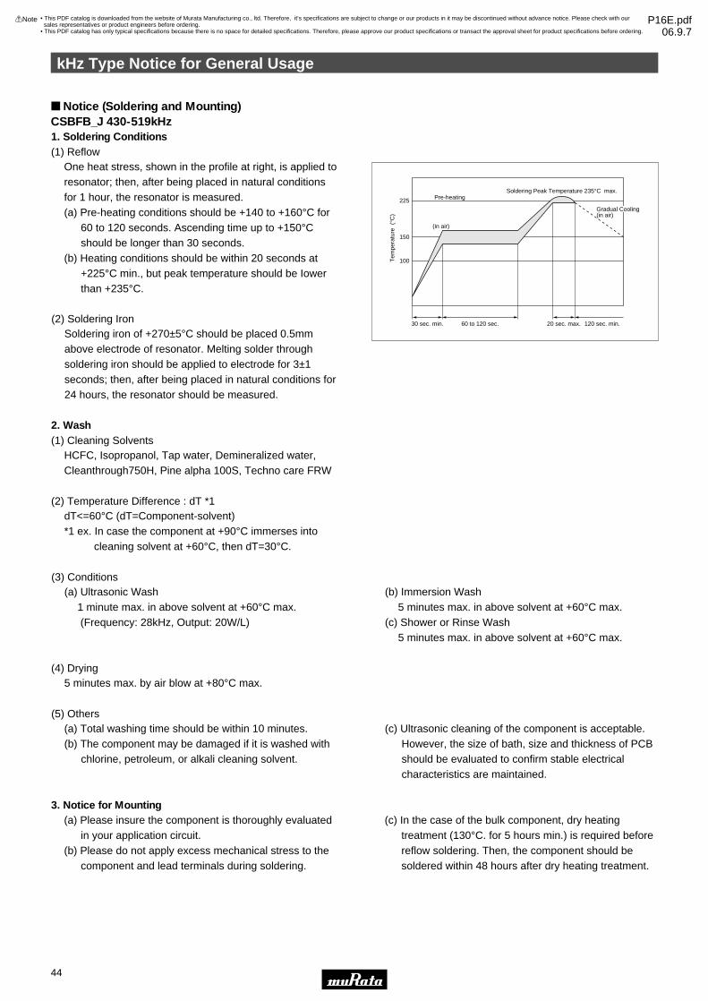
One heat stress, shown in the profile at right, is applied to resonator; then, after being placed in natural conditions for 1 hour, the resonator is measured. (a) Pre-heating conditions should be +140 to +160°C for
60 to 120 seconds. Ascending time up to +150°C should be longer than 30 seconds.
(b) Heating conditions should be within 20 seconds at +225°C min., but peak temperature should be Iower than +235°C.
1. Soldering Conditions (1) Reflow
HCFC, Isopropanol, Tap water, Demineralized water, Cleanthrough750H, Pine alpha 100S, Techno care FRW
2. Wash
3. Notice for Mounting
(1) Cleaning Solvents
dT<=60°C (dT=Component-solvent) *1 ex. In case the component at +90°C immerses into cleaning solvent at +60°C, then dT=30°C.
(2) Temperature Difference : dT *1
5 minutes max. by air blow at +80°C max. (4) Drying
(a) Total washing time should be within 10 minutes. (b) The component may be damaged if it is washed with
chlorine, petroleum, or alkali cleaning solvent.
(c) Ultrasonic cleaning of the component is acceptable. However, the size of bath, size and thickness of PCB should be evaluated to confirm stable electrical characteristics are maintained.
(5) Others
(a) Ultrasonic Wash 1 minute max. in above solvent at +60°C max. (Frequency: 28kHz, Output: 20W/L)
(b) Immersion Wash 5 minutes max. in above solvent at +60°C max.
(c) Shower or Rinse Wash 5 minutes max. in above solvent at +60°C max.
(3) Conditions
Soldering iron of +270±5°C should be placed 0.5mm above electrode of resonator. Melting solder through soldering iron should be applied to electrode for 3±1 seconds; then, after being placed in natural conditions for 24 hours, the resonator should be measured.
(2) Soldering Iron
Tem
pera
ture
(°C
)
225 Pre-heating
(in air)
Soldering Peak Temperature 235°C max.
30 sec. min. 60 to 120 sec. 20 sec. max. 120 sec. min.
150
100
Gradual Cooling(in air)
(a) Please insure the component is thoroughly evaluated in your application circuit.
(b) Please do not apply excess mechanical stress to the component and lead terminals during soldering.
(c) In the case of the bulk component, dry heating treatment (130°C. for 5 hours min.) is required before reflow soldering. Then, the component should be soldered within 48 hours after dry heating treatment.
Notice (Soldering and Mounting)CSBFB_J 430-519kHz
kHz Type Notice for General Usage
44
7
!Note • Please read rating and !CAUTION (for storage, operating, rating, soldering, mounting and handling) in this catalog to prevent smoking and/or burning, etc.• This catalog has only typical specifications because there is no space for detailed specifications. Therefore, please approve our product specifications or transact the approval sheet for product specifications before ordering.
• This PDF catalog is downloaded from the website of Murata Manufacturing co., ltd. Therefore, it’s specifications are subject to change or our products in it may be discontinued without advance notice. Please check with our sales representatives or product engineers before ordering.
• This PDF catalog has only typical specifications because there is no space for detailed specifications. Therefore, please approve our product specifications or transact the approval sheet for product specifications before ordering.
!Note P16E.pdf06.9.7
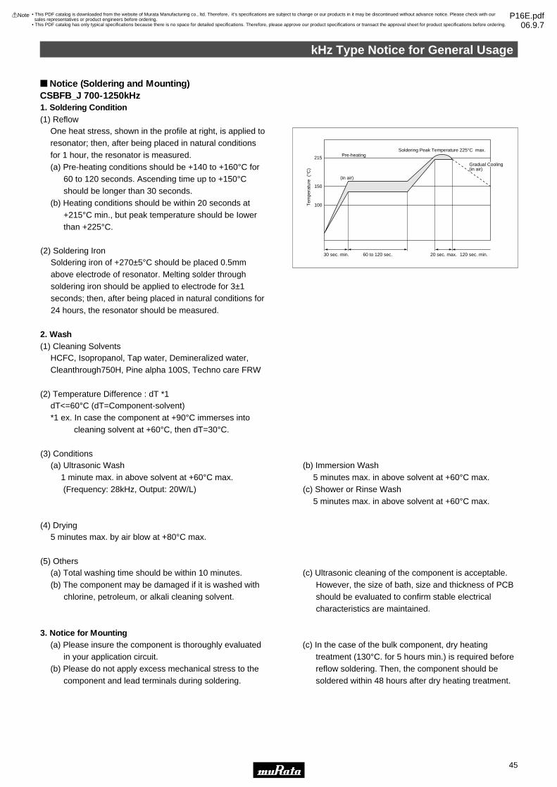
One heat stress, shown in the profile at right, is applied to resonator; then, after being placed in natural conditions for 1 hour, the resonator is measured. (a) Pre-heating conditions should be +140 to +160°C for
60 to 120 seconds. Ascending time up to +150°C should be longer than 30 seconds.
(b) Heating conditions should be within 20 seconds at +215°C min., but peak temperature should be Iower than +225°C.
1. Soldering Condition (1) Reflow
HCFC, Isopropanol, Tap water, Demineralized water, Cleanthrough750H, Pine alpha 100S, Techno care FRW
2. Wash
3. Notice for Mounting
(1) Cleaning Solvents
dT<=60°C (dT=Component-solvent) *1 ex. In case the component at +90°C immerses into cleaning solvent at +60°C, then dT=30°C.
(2) Temperature Difference : dT *1
5 minutes max. by air blow at +80°C max. (4) Drying
(a) Total washing time should be within 10 minutes. (b) The component may be damaged if it is washed with
chlorine, petroleum, or alkali cleaning solvent.
(c) Ultrasonic cleaning of the component is acceptable. However, the size of bath, size and thickness of PCB should be evaluated to confirm stable electrical characteristics are maintained.
(5) Others
(a) Ultrasonic Wash 1 minute max. in above solvent at +60°C max. (Frequency: 28kHz, Output: 20W/L)
(b) Immersion Wash 5 minutes max. in above solvent at +60°C max.
(c) Shower or Rinse Wash 5 minutes max. in above solvent at +60°C max.
(3) Conditions
Soldering iron of +270±5°C should be placed 0.5mm above electrode of resonator. Melting solder through soldering iron should be applied to electrode for 3±1 seconds; then, after being placed in natural conditions for 24 hours, the resonator should be measured.
(2) Soldering Iron
Tem
pera
ture
(°C
)
215 Pre-heating
(in air)
Soldering Peak Temperature 225°C max.
30 sec. min. 60 to 120 sec. 20 sec. max. 120 sec. min.
150
100
Gradual Cooling(in air)
(a) Please insure the component is thoroughly evaluated in your application circuit.
(b) Please do not apply excess mechanical stress to the component and lead terminals during soldering.
(c) In the case of the bulk component, dry heating treatment (130°C. for 5 hours min.) is required before reflow soldering. Then, the component should be soldered within 48 hours after dry heating treatment.
Notice (Soldering and Mounting)CSBFB_J 700-1250kHz
kHz Type Notice for General Usage
45
7
!Note • Please read rating and !CAUTION (for storage, operating, rating, soldering, mounting and handling) in this catalog to prevent smoking and/or burning, etc.• This catalog has only typical specifications because there is no space for detailed specifications. Therefore, please approve our product specifications or transact the approval sheet for product specifications before ordering.
• This PDF catalog is downloaded from the website of Murata Manufacturing co., ltd. Therefore, it’s specifications are subject to change or our products in it may be discontinued without advance notice. Please check with our sales representatives or product engineers before ordering.
• This PDF catalog has only typical specifications because there is no space for detailed specifications. Therefore, please approve our product specifications or transact the approval sheet for product specifications before ordering.
!Note P16E.pdf06.9.7

kHz Type Notice for General Usage
46
7
!Note • Please read rating and !CAUTION (for storage, operating, rating, soldering, mounting and handling) in this catalog to prevent smoking and/or burning, etc.• This catalog has only typical specifications because there is no space for detailed specifications. Therefore, please approve our product specifications or transact the approval sheet for product specifications before ordering.
Notice (Soldering and Mounting)CSBLA_EThe component cannot withstand washing.Please do not apply excessive mechanical stress to thecomponent and lead terminals during soldering.
Notice (Soldering and Mounting)CSBLA_J1. Cleaning Solvents HCFC, Isopropanol, Tap water, Demineralized water, Cleanthrough750H, Pine alpha 100S, Techno care FRW.2. Temperature Difference: dT *1 dT<=30 C. (dT=Component-solvent) *1 ex. In case the component at +90 degree C immerses into cleaning solvent at +60 degree C, then dT=30 degree C.3. Conditions (1) Ultrasonic Wash 1 minute max. in above solvent at +60 degree C max. (Frequency: 28kHz, Output: 20W/L) (2) Immersion Wash 5 minutes max. in above solvent at +60 degree C max. (3) Shower or Rinse Wash 5 minutes max. in above solvent at +60 degree C max.
4. Drying 5 minutes max. by air blow at +80 degree C max.5. Others (1) Total washing time should be within 10 minutes. (2) Please insure the component is thoroughly evaluated in your application circuit. (3) The component may be damaged if it is washed with alkali cleaning solvent. (4) Please do not apply excess mechanical stress to the component and lead terminals during soldering. (5) Ultrasonic cleaning of the component is acceptable. However, the size of bath, size and thickness of PCB should be evaluated to confirm stable electrical characteristics are maintained.
Notice (Storage and Operating Condition)CSBFB_J/CSBLA_J1. Product Storage Condition Please store the products in room where the temperature/humidity is stable. And avoid such places where there are large temperature changes. Please store the products under the following conditions: Temperature: -10 to + 40 degree C Humidity: 15 to 85% R.H.2. Expire Date on Storage Expire date (Shelf life) of the products is six months after delivery under the conditions of a sealed and an unopened package. Please use the products within six months after delivery. If you store the products for a long time (more than six months), use carefully because the products may be degraded in the solderability and/or rusty. Please confirm solderability and characteristics for the products regularly.3. Notice on Product Storage (1) Please do not store the products in a chemical atmosphere (Acids, Alkali, Bases, Organic gas, Sulfides and so on), because the characteristics may be reduced in quality, and/or be degraded in the solderability due to the storage in a chemical atmosphere.
(2) Please do not put the products directly on the floor without anything under them to avoid damp places and/or dusty places. (3) Please do not store the products in the places such as: in a damp heated place, in a place where direct sunlight comes in, in place applying vibrations. (4) Please use the products immediately after the package is opened, because the characteristics may be reduced in quality, and/or be degraded in the solderability due to storage under the poor condition. (5) Please do not drop the products to avoid cracking of ceramic element.4. Others Conformal coating of the component is acceptable. However, the resin material, curing temperature, and other process conditions should be evaluated to confirm that stable electrical characteristics are maintained. Please be sure to consult with our sales representative or engineer whenever and prior to using the products.
• This PDF catalog is downloaded from the website of Murata Manufacturing co., ltd. Therefore, it’s specifications are subject to change or our products in it may be discontinued without advance notice. Please check with our sales representatives or product engineers before ordering.
• This PDF catalog has only typical specifications because there is no space for detailed specifications. Therefore, please approve our product specifications or transact the approval sheet for product specifications before ordering.
!Note P16E.pdf06.9.7

kHz Type Notice for General Usage
47
7
!Note • Please read rating and !CAUTION (for storage, operating, rating, soldering, mounting and handling) in this catalog to prevent smoking and/or burning, etc.• This catalog has only typical specifications because there is no space for detailed specifications. Therefore, please approve our product specifications or transact the approval sheet for product specifications before ordering.
Notice (Storage and Operating Condition)CSBLA_E1. Product Storage Condition Please store the products in room where the temperature/humidity is stable. And avoid such places where there are large temperature changes. Please store the products under the following conditions: Temperature: -10 to + 40 degree C Humidity: 15 to 85% R.H.2. Expire Date on Storage Expire date (Shelf life) of the products is six months after delivery under the conditions of a sealed and an unopened package. Please use the products within six months after delivery. If you store the products for a long time (more than six months), use carefully because the products may be degraded in the solderability and/or rusty. Please confirm solderability and characteristics for the products regularly.3. Notice on Product Storage (1) Please do not store the products in a chemical atmosphere (Acids, Alkali, Bases, Organic gas, Sulfides and so on), because the characteristics may be reduced in quality, and/or be degraded in the solderability due to the storage in a chemical atmosphere.
(2) Please do not put the products directly on the floor without anything under them to avoid damp places and/or dusty places. (3) Please do not store the products in the places such as: in a damp heated place, in a place where direct sunlight comes in, in place applying vibrations. (4) Please use the products immediately after the package is opened, because the characteristics may be reduced in quality, and/or be degraded in the solderability due to storage under the poor condition. (5) Please do not drop the products to avoid cracking of ceramic element.4. Others Conformal coating or washing of the component is not acceptable because it is not hermetically sealed. Please be sure to consult with our sales representative or engineer whenever and prior to using the products.
Notice (Rating)The component may be damaged if excess mechanical stress is applied.
Notice (Handling)"CERALOCK" may stop oscillating or oscillate irregularly under improper circuit conditions.
• This PDF catalog is downloaded from the website of Murata Manufacturing co., ltd. Therefore, it’s specifications are subject to change or our products in it may be discontinued without advance notice. Please check with our sales representatives or product engineers before ordering.
• This PDF catalog has only typical specifications because there is no space for detailed specifications. Therefore, please approve our product specifications or transact the approval sheet for product specifications before ordering.
!Note P16E.pdf06.9.7

MHz Chip Type Packaging for General Usage
48
7
!Note • Please read rating and !CAUTION (for storage, operating, rating, soldering, mounting and handling) in this catalog to prevent smoking and/or burning, etc.• This catalog has only typical specifications because there is no space for detailed specifications. Therefore, please approve our product specifications or transact the approval sheet for product specifications before ordering.
Minimum Quantity
(in mm)
a b
CSTCC_G
CSTCR_G
CSTCR_G15B
CSTCE_G
CSTCE_G15L
CSTCE_V
CSTCE_V13L
CSTCE_XK
CSTCG_V
CSTCZ_X12R
CSTCW_X
CSTCW_X11
CSTCW_X_M
CSACW_X
Part Number Plastic Tape ø180mm Plastic Tape ø330mm Bulk Dimensions
2,000
3,000
3,000
3,000
3,000
3,000
3,000
3,000
3,000
3,000
3,000
3,000
3,000
3,000
6,000
9,000
9,000
9,000
9,000
9,000
9,000
9,000
9,000
9,000
9,000
9,000
9,000
9,000
500
500
500
500
500
500
500
500
500
500
500
500
500
500
a
a
a
b
b
b
b
b
b
b
b
b
b
b
(ø18
0
)
17.0±1.0
ø13.0±0.2 2.0±0.5
160-190Trailer Leader
Empty
400-560
Cover Film
Components
Trailer160-190
Empty160 min.
Empty160 min.
400-560
Cover FilmLeader
Empty Components
ø13.0±0.22.0±0.5
+1.0–09.0
13.0±1.0
(pcs.)
c Dimensions of Reel
The order quantity should be an integral multiple of the "Minimum Quantity" shown above.
13.0 +1.00
0 –1.5
(ø18
0
)
0 –1.5
Dimensions of TapingCSTCR_G15
(in mm)
4.0±0.1
2.0±0.05
(9.5
)
4.0±0.1
(3)
(2)
(1)
ø1.5W0.1Y0
ø1.5W0.1Y0
12.0
±0.2
5.5±
0.05
1.75
±0.1
4.7±
0.1
0.3±
0.05
1.25
±0.0
5
(1.8
5 m
ax.)2.2±0.1
Direction of Feed
3˚ max.
10˚Cover Film
The cover film peel strength force 0.1 to 0.7NThe cover film peel speed 300mm/min.
CSTCE_G15L
(in mm)
2.0±0.05
4.0±0.1
3° max.
3.5±
0.05
8.0±
0.2
1.75
±0.1
0.25
±0.0
5
0.90
±0.1
0
(1.3
0 m
ax.)
10°
(5.2
)
Cover Film
Direction of Feed
The cover film peel strength force 0.1 to 0.7N The cover film peel speed 300mm/min.
4.0±0.1
1.50±0.1
ø1.5 -0.0+0.1
ø1.0 -0.0+0.2
3.40
±0.1
(3)
(2)
(1)
Continued on the following page.
• This PDF catalog is downloaded from the website of Murata Manufacturing co., ltd. Therefore, it’s specifications are subject to change or our products in it may be discontinued without advance notice. Please check with our sales representatives or product engineers before ordering.
• This PDF catalog has only typical specifications because there is no space for detailed specifications. Therefore, please approve our product specifications or transact the approval sheet for product specifications before ordering.
!Note P16E.pdf06.9.7

MHz Chip Type Packaging for General Usage
49
7
!Note • Please read rating and !CAUTION (for storage, operating, rating, soldering, mounting and handling) in this catalog to prevent smoking and/or burning, etc.• This catalog has only typical specifications because there is no space for detailed specifications. Therefore, please approve our product specifications or transact the approval sheet for product specifications before ordering.
Continued from the preceding page.
Dimensions of TapingCSTCE_V13L
Dimensions of Carrier Tape
(in mm)
4.0±0.1
Cover Film
4.0±0.1
2.0±0.05
8.0±
0.2
ø1.5+0.1-0.0
ø1.0+0.1-0.0
3.5±
0.05
1.75
±0.1
3.45
±0.1
Direction of Feed
0.25
±0.0
5
(1.4
0 m
ax.)
1.10
±0.0
5
3˚ max.
1.50±0.1The cover film peel strength force 0.1 to 0.7NThe cover film peel speed 300mm/min.
10˚
(5.2
)
(2)
(3)
(1)
CSTCE_XK
(in mm)
2.0±0.05
4.0±0.1
3° max.
3.5±
0.05
8.0±
0.2
1.75
±0.1
0.25
±0.0
5
1.15
±0.1
(1.5
0 m
ax.)
10°
(5.2
)
Cover Film
Direction of Feed
The cover film peel strength force 0.1 to 0.7N The cover film peel speed 300mm/min.
4.0±0.1
1.50±0.1
ø1.5 -0.0+0.1
ø1.0 -0.0+0.2
3.40
±0.1
(3)
(2)
(1)
CSTCW_X11
(in mm)
Thickness of CERALOCKr
∗1, ∗2 : Dimensions vary with product thickness of CERALOCKr
1.40–1.20 1.15–1.00 0.95–0.90
t1 ∗1t2 ∗2
1.48±0.12.1 max.
1.30±0.11.9 max.
1.12±0.11.7 max.
4.0±0.1
2.8±
0.1 3.5±
0.1
1.75
±0.1
(1)
(3)
(2)
8.0±
0.2
0.2±
0.1
t2t1
∗2∗1
(5.5
)
2.0±0.1
4.0±0.1
3° max.10°
Cover Film
The cover film peel strength force 0.1 to 0.7NThe cover film peel speed 300mm/min.
+0.1-0.0ø1.5
+0.1-0.052.3
+0.2-0.0ø1.0
Direction of Feed
CSTCZ-X12R
(in mm)
4.0±0.1
2.2±
0.1 3.5±
0.1
1.75
±0.1
(1)
(3)
(2)
8.0±
0.2
0.2±
0.1
1.6
max
.
1.10
±0.1
(5.5
)
2.0±0.1
4.0±0.1
3° max.10°
Cover Film
The cover film peel strength force 0.1 to 0.7NThe cover film peel speed 300mm/min.
+0.1-0.0ø1.5
1.8±0.1
+0.2-0.0ø1.0
Direction of Feed
CSTCC_G less than 3.00MHz
(in mm)
4.0±0.12.0±0.05
+0.3-0.0
ø1.55±0.05
ø1.5
1.75
±0.1
5.5±
0.05
12.0
±0.2
7.6±
0.1
4.0±0.1
(9.5
)
3.3±0.1
The cover film peel strength force 0.1 to 0.7NThe cover film peel speed 300mm/min.
Cover film10˚
3˚max.
1.85
±0.0
5
0.3±
0.05
(2.4
5 m
ax.)
Direction of Feed
(3)
(2)
(1)
CSTCC_G more than 3.00MHz
(in mm)
4.0±0.12.0±0.05
+0.3-0.0
φ1.55±0.05
φ1.5
1.75
±0.1
5.5±
0.05
12.0
±0.2
7.6±
0.1
4.0±0.1
(9.5
) (1)
(2)
(3)
3.3±0.1
The cover film peel strength force 0.1 to 0.7NThe cover film peel speed 300mm/min.
Cover film10˚
3˚max.
1.65
±0.0
5
0.3±
0.05
(2.2
5 m
ax.)
Direction of Feed
Continued on the following page.
• This PDF catalog is downloaded from the website of Murata Manufacturing co., ltd. Therefore, it’s specifications are subject to change or our products in it may be discontinued without advance notice. Please check with our sales representatives or product engineers before ordering.
• This PDF catalog has only typical specifications because there is no space for detailed specifications. Therefore, please approve our product specifications or transact the approval sheet for product specifications before ordering.
!Note P16E.pdf06.9.7

MHz Chip Type Packaging for General Usage
50
7
!Note • Please read rating and !CAUTION (for storage, operating, rating, soldering, mounting and handling) in this catalog to prevent smoking and/or burning, etc.• This catalog has only typical specifications because there is no space for detailed specifications. Therefore, please approve our product specifications or transact the approval sheet for product specifications before ordering.
Continued from the preceding page.
Dimensions of TapingCSTCR_G
(in mm)
4.0±0.1
2.0±0.05
(9.5
)
4.0±0.1
(3)
(2)
(1)
ø1.5W0.1Y0
ø1.5W0.1Y0
12.0
±0.2
5.5±
0.05
1.75
±0.1
4.7±
0.1
0.3±
0.05
1.25
±0.0
5
(1.8
5 m
ax.)2.2±0.1
Direction of Feed
3˚ max.
10˚Cover Film
The cover film peel strength force 0.1 to 0.7NThe cover film peel speed 300mm/min.
CSTCE_G
(in mm)
2.0±0.05
4.0±0.1
3° max.
3.5±
0.05
8.0±
0.2
1.75
±0.1
0.25
±0.0
5
0.90
±0.1
0
(1.3
0 m
ax.)
10°
(5.2
)
Cover Film
Direction of Feed
The cover film peel strength force 0.1 to 0.7N The cover film peel speed 300mm/min.
4.0±0.1
1.50±0.1
ø1.5 -0.0+0.1
ø1.0 -0.0+0.2
3.40
±0.1
(3)
(2)
(1)
CSTCE_VDimensions of Carrier Tape
(in mm)
4.0±0.1
Cover Film
4.0±0.1
2.0±0.05
8.0±
0.2
ø1.5+0.1-0.0
ø1.0+0.1-0.0
3.5±
0.05
1.75
±0.1
3.45
±0.1
Direction of Feed
0.25
±0.0
5
(1.4
0 m
ax.)
1.10
±0.0
5
3˚ max.
1.50±0.1The cover film peel strength force 0.1 to 0.7NThe cover film peel speed 300mm/min.
10˚
(5.2
)
(2)
(3)
(1)
CSTCG_V
(in mm)
4.0±0.1
Dimensions of Carrier Tape
Cover Film
4.0±0.1
2.0±0.05
8.0±
0.2
ø1.5+0.1-0.0
ø1.0+0.1-0.0
3.5±
0.05
1.75
±0.1
2.2±
0.05
Direction of Feed
0.25
±0.0
5
(1.3
0 m
ax.)
1.00
±0.0
5
3 max.
1.50±0.1The cover film peel strength force 0.1 to 0.7NThe cover film peel speed 300mm/min.
10˚
(5.2
)
(2)
(3)
(1)
CSACW_X
(in mm)
Thickness of CERALOCKr
∗1, ∗2 : Dimensions vary with product thickness of CERALOCKr
1.40–1.20 1.15–1.00 0.95–0.90t1 ∗1t2 ∗2
1.48±0.12.1 max.
1.30±0.11.9 max.
1.12±0.11.7 max.
4.0±0.1
2.8±
0.1 3.5±
0.1
1.75
±0.1
8.0±
0.2
0.3±
0.1
t2t1
(5.5
)
2.0±0.1
4.0±0.1
3° max.10°
Cover Film
The cover film peel strength force 0.1 to 0.7NThe cover film peel speed 300mm/min.
+0.1-0.0ø1.5
+0.1-0.052.3
+0.2-0.0ø1.0
Direction of Feed
∗1 ∗2
CSTCW_X
(in mm)
Thickness of CERALOCKr
∗1, ∗2 : Dimensions vary with product thickness of CERALOCKr
1.40–1.20 1.15–1.00 0.95–0.90
t1 ∗1t2 ∗2
1.48±0.12.1 max.
1.30±0.11.9 max.
1.12±0.11.7 max.
4.0±0.1
2.8±
0.1 3.5±
0.1
1.75
±0.1
(1)
(3)
(2)
8.0±
0.2
0.2±
0.1
t2t1
∗2∗1
(5.5
)
2.0±0.1
4.0±0.1
3° max.10°
Cover Film
The cover film peel strength force 0.1 to 0.7NThe cover film peel speed 300mm/min.
+0.1-0.0ø1.5
+0.1-0.052.3
+0.2-0.0ø1.0
Direction of Feed
CSTCW_X_M
(in mm)
∗1, ∗2 : Dimensions vary with product thickness of CERALOCKr
1.40–1.20 1.15–1.00 0.95–0.70
t1 ∗1
t2 ∗2
1.48±0.1
2.1 max.
1.30±0.1
1.9 max.
1.12±0.1
1.7 max.
4.0±0.1
2.8±
0.1 3.5±
0.1
1.75
±0.1
(1)
(3)
(2)
8.0±
0.2
0.2±
0.1
t2t1
∗2∗1
(5.5
)
2.0±0.1
4.0±0.1
3° max.10°
Cover Film
The cover film peel strength force 0.1 to 0.7NThe cover film peel speed 300mm/min.
+0.1-0.0ø1.5
2.3±0.1
+0.2-0.0ø1.0
Thickness of CERALOCKr
Direction of Feed
• This PDF catalog is downloaded from the website of Murata Manufacturing co., ltd. Therefore, it’s specifications are subject to change or our products in it may be discontinued without advance notice. Please check with our sales representatives or product engineers before ordering.
• This PDF catalog has only typical specifications because there is no space for detailed specifications. Therefore, please approve our product specifications or transact the approval sheet for product specifications before ordering.
!Note P16E.pdf06.9.7

MHz Lead Type Packaging for General Usage
51
7
!Note • Please read rating and !CAUTION (for storage, operating, rating, soldering, mounting and handling) in this catalog to prevent smoking and/or burning, etc.• This catalog has only typical specifications because there is no space for detailed specifications. Therefore, please approve our product specifications or transact the approval sheet for product specifications before ordering.
Minimum QuantityPart Number Ammo Pack
(pcs.)The order quantity should be an integral multiple of the "Minimum Quantity" shown above.
Bulk
500
500
CSTLS_G (3.40 to 10.0MHz) 2,000
CSTLS_X (16.00 to 70.00MHz) 2,000
Tape Dimensions of CSTLS_G
(in mm)
Width of diameter
Height of resonator
Dimensions of terminal
Lead length under the hold down tape
Pitch of component
Pitch of sprocket hole
Length from sprocket hole center to lead
Length from sprocket hole center to component center
Lead spacing (I)
Lead spacing (II)
Slant forward or backward
Width of carrier tape
Width of hold down tape
Position of sprocket hole
Gap of hold down tape and carrier tape
Distance between the center of sprocket hole and lead stopper
Total height of resonator
Diameter of sprocket hole
Total tape thickness
Body tilt
Item Code Dimensions Tolerance Remarks
D
A
d
L1
P
P0
P1
P2
F1
F2
dh
W
W0
W1
W2
H0
H1
D0
t
dS
8.0
5.5
ø0.48
5.0 min.
12.7
12.7
3.85
6.35
2.5
2.5
0
18.0
6.0 min.
9.0
0
18.0
23.5
ø4.0
0.6
0
±1.0
±0.5
±0.05
–
±0.5
±0.2
±0.5
±0.5
±0.2
±0.2
±1.0
±0.5
–
±0.5
±0.5
±1.0
±0.2
±0.2
±1.0
Tolerance for Pitches 10xP0=127±1
1mm max.
Hold down tape does not exceed the carrier tape.
W0.5Y0
M∗ M∗∗ ∗∗ ∗
P2
D
A
P
dS
W
H0
H1
W1W
0
L1
W2
D0
tP0
P1 F1 F2
Direction of Feed
dh dh
d
Continued on the following page.
• This PDF catalog is downloaded from the website of Murata Manufacturing co., ltd. Therefore, it’s specifications are subject to change or our products in it may be discontinued without advance notice. Please check with our sales representatives or product engineers before ordering.
• This PDF catalog has only typical specifications because there is no space for detailed specifications. Therefore, please approve our product specifications or transact the approval sheet for product specifications before ordering.
!Note P16E.pdf06.9.7
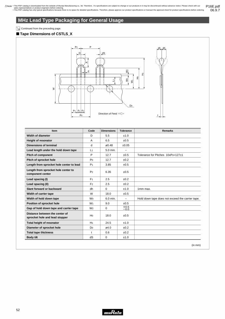
MHz Lead Type Packaging for General Usage
52
7
!Note • Please read rating and !CAUTION (for storage, operating, rating, soldering, mounting and handling) in this catalog to prevent smoking and/or burning, etc.• This catalog has only typical specifications because there is no space for detailed specifications. Therefore, please approve our product specifications or transact the approval sheet for product specifications before ordering.
Continued from the preceding page.
Tape Dimensions of CSTLS_X
(in mm)
Width of diameter
Height of resonator
Dimensions of terminal
Lead length under the hold down tape
Pitch of component
Pitch of sprocket hole
Length from sprocket hole center to lead
Length from sprocket hole center to component center
Lead spacing (I)
Lead spacing (II)
Slant forward or backward
Width of carrier tape
Width of hold down tape
Position of sprocket hole
Gap of hold down tape and carrier tape
Distance between the center of sprocket hole and lead stopper
Total height of resonator
Diameter of sprocket hole
Total tape thickness
Body tilt
Item Code Dimensions Tolerance Remarks
D
A
d
L1
P
P0
P1
P2
F1
F2
dh
W
W0
W1
W2
H0
H1
D0
t
dS
5.5
6.5
ø0.48
5.0 min.
12.7
12.7
3.85
6.35
2.5
2.5
0
18.0
6.0 min.
9.0
0
18.0
24.5
ø4.0
0.6
0
±1.0
±0.5
±0.05
–
±0.5
±0.2
±0.5
±0.5
±0.2
±0.2
±1.0
±0.5
–
±0.5
±0.5
±1.0
±0.2
±0.2
±1.0
Tolerance for Pitches 10xP0=127±1
1mm max.
Hold down tape does not exceed the carrier tape.
W0.5Y0.0
D dS
d
P2 P
A
W0
L1 W1
W2
H0
H1
P1
P0 t
F1 F2
W
D0
dh dh
Direction of Feed
• This PDF catalog is downloaded from the website of Murata Manufacturing co., ltd. Therefore, it’s specifications are subject to change or our products in it may be discontinued without advance notice. Please check with our sales representatives or product engineers before ordering.
• This PDF catalog has only typical specifications because there is no space for detailed specifications. Therefore, please approve our product specifications or transact the approval sheet for product specifications before ordering.
!Note P16E.pdf06.9.7

MHz Lead Type Packaging for General Usage
53
7
!Note • Please read rating and !CAUTION (for storage, operating, rating, soldering, mounting and handling) in this catalog to prevent smoking and/or burning, etc.• This catalog has only typical specifications because there is no space for detailed specifications. Therefore, please approve our product specifications or transact the approval sheet for product specifications before ordering.
Tape Dimensions of CSALS
(in mm)
Width of diameter
Height of resonator
Dimensions of terminal
Lead length under the hold down tape
Pitch of component
Pitch of sprocket hole
Length from sprocket hole center to lead
Length from sprocket hole center to component center
Lead spacing
Slant forward or backward
Width of carrier tape
Width of hold down tape
Position of sprocket hole
Gap of hold down tape and carrier tape
Distance between the center of sprocket hole and lead stopper
Total height of resonator
Diameter of sprocket hole
Total tape thickness
Body tilt
Item Code Dimensions Tolerance Remarks
D
A
d
L1
P
P0
P1
P2
F
dh
W
W0
W1
W2
H0
H1
D0
t
dS
5.5
6.5
ø0.48
5.0 min.
12.7
12.7
3.85
6.35
5.0
0
18.0
6.0 min.
9.0
0
18.0
24.5
ø4.0
0.6
0
±1.0
±0.5
±0.05
———
±0.5
±0.2
±0.5
±0.5
±0.3
±1.0
±0.5
———
±0.5
±0.5
±1.0
±0.2
±0.2
±1.0
Tolerance for Pitches 10xP0=127±1
1mm max.
Hold down tape does not exceed the carrier tape.
+0.5- 0
D dS
d
P2 P
A
W0
L1 W1
W2
H0
H1
P1
P0 t
F
W
D0
dh dh
Direction of Feed
Minimum Quantity
CSALS_X (16.00 to 70.00MHz)
Part Number Ammo Pack
2,000
Bulk
500
(pcs.)The order quantity should be an integral multiple of the "Minimum Quantity" shown above.
• This PDF catalog is downloaded from the website of Murata Manufacturing co., ltd. Therefore, it’s specifications are subject to change or our products in it may be discontinued without advance notice. Please check with our sales representatives or product engineers before ordering.
• This PDF catalog has only typical specifications because there is no space for detailed specifications. Therefore, please approve our product specifications or transact the approval sheet for product specifications before ordering.
!Note P16E.pdf06.9.7
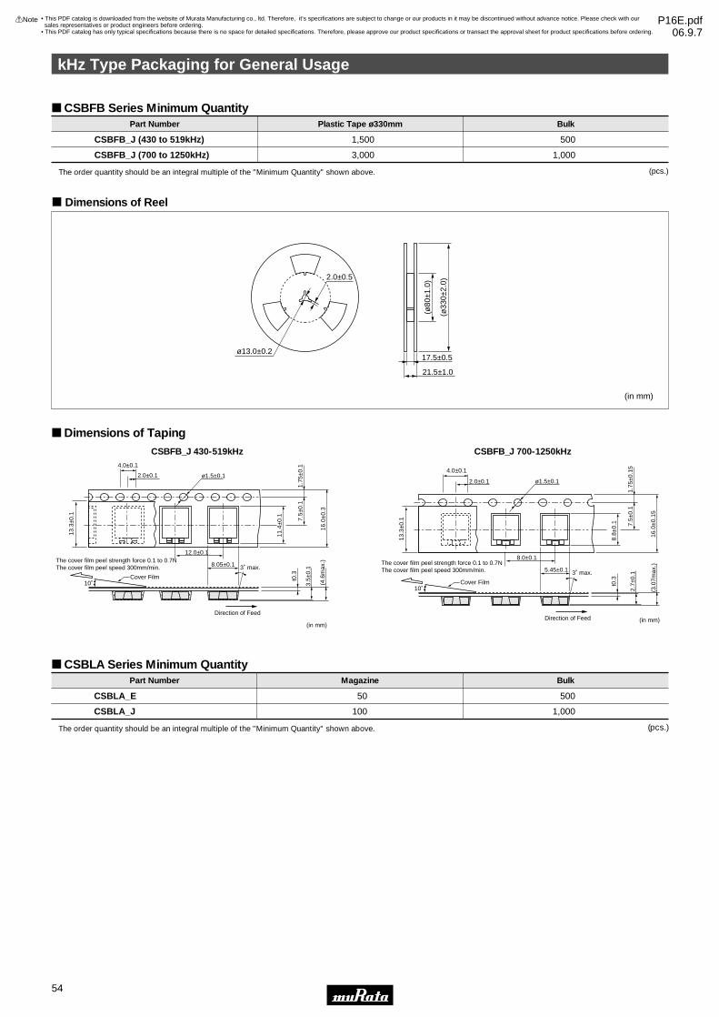
kHz Type Packaging for General Usage
54
7
!Note • Please read rating and !CAUTION (for storage, operating, rating, soldering, mounting and handling) in this catalog to prevent smoking and/or burning, etc.• This catalog has only typical specifications because there is no space for detailed specifications. Therefore, please approve our product specifications or transact the approval sheet for product specifications before ordering.
CSBFB Series Minimum Quantity
(in mm)
CSBFB_J (430 to 519kHz)
CSBFB_J (700 to 1250kHz)
Part Number BulkPlastic Tape ø330mm
1,500
3,000
500
1,000
ø13.0±0.2
2.0±0.5
(ø80
±1.0
)
(ø33
0±2.
0)
17.5±0.5
21.5±1.0
(pcs.)The order quantity should be an integral multiple of the "Minimum Quantity" shown above.
c Dimensions of Reel
Dimensions of TapingCSBFB_J 430-519kHz
(in mm)
4.0±0.1
13.3
±0.1
11.4
±0.1
t0.3
3.5±
0.1
(4.6
max
.)
7.5±
0.1
16.0
±0.3
1.75
±0.1
2.0±0.1
12.0±0.1
8.05±0.1
Direction of Feed
Cover Film
3˚ max.
10˚
ø1.5±0.1
The cover film peel strength force 0.1 to 0.7NThe cover film peel speed 300mm/min.
CSBFB_J 700-1250kHz
(in mm)
4.0±0.1
13.3
±0.1
8.8±
0.1
t0.3
2.7±
0.1
(3.0
7max
.)
7.5±
0.1
16.0
±0.1
5
1.75
±0.1
5
2.0±0.1
8.0±0.1
5.45±0.1
Direction of Feed
Cover Film
3˚ max.
10˚
ø1.5±0.1
The cover film peel strength force 0.1 to 0.7NThe cover film peel speed 300mm/min.
CSBLA Series Minimum Quantity
CSBLA_E
CSBLA_J
Part Number Magazine
50
100
Bulk
500
1,000
(pcs.)The order quantity should be an integral multiple of the "Minimum Quantity" shown above.
• This PDF catalog is downloaded from the website of Murata Manufacturing co., ltd. Therefore, it’s specifications are subject to change or our products in it may be discontinued without advance notice. Please check with our sales representatives or product engineers before ordering.
• This PDF catalog has only typical specifications because there is no space for detailed specifications. Therefore, please approve our product specifications or transact the approval sheet for product specifications before ordering.
!Note P16E.pdf06.9.7

Head Office1-10-1, Higashi Kotari, Nagaokakyo-shi, Kyoto 617-8555, JapanPhone: 81-75-951-9111
International Division3-29-12, Shibuya, Shibuya-ku, Tokyo 150-0002, Japan Phone: 81-3-5469-6123 Fax: 81-3-5469-6155 E-mail: [email protected]
http://www.murata.com/
• This PDF catalog is downloaded from the website of Murata Manufacturing co., ltd. Therefore, it’s specifications are subject to change or our products in it may be discontinued without advance notice. Please check with our sales representatives or product engineers before ordering.
• This PDF catalog has only typical specifications because there is no space for detailed specifications. Therefore, please approve our product specifications or transact the approval sheet for product specifications before ordering.
!Note P16E.pdf06.9.7
Note:1. Export Control
<For customers outside Japan>Murata products should not be used or sold for use in the development, production, stockpiling or utilization of any conventional weapons or mass-destructiveweapons (nuclear weapons, chemical or biological weapons, or missiles), or any other weapons.<For customers in Japan>For products which are controlled items subject to the “Foreign Exchange and Foreign Trade Law” of Japan, the export license specified by the law is requiredfor export.
2. Please contact our sales representatives or product engineers before using the products in this catalog for the applications listed below, which require especiallyhigh reliability for the prevention of defects which might directly damage a third party's life, body or property, or when one of our products is intended for use inapplications other than those specified in this catalog.q Aircraft equipment w Aerospace equipmente Undersea equipment r Power plant equipmentt Medical equipment y Transportation equipment (vehicles, trains, ships, etc.)u Traffic signal equipment i Disaster prevention / crime prevention equipmento Data-processing equipment !0 Application of similar complexity and/or reliability requirements to the applications listed above
3. Product specifications in this catalog are as of July 2006. They are subject to change or our products in it may be discontinued without advance notice. Pleasecheck with our sales representatives or product engineers before ordering. If there are any questions, please contact our sales representatives or productengineers.
4. Please read rating and CAUTION (for storage, operating, rating, soldering, mounting and handling) in this catalog to prevent smoking and/or burning, etc.
5. This catalog has only typical specifications because there is no space for detailed specifications. Therefore, please approve our product specifications ortransact the approval sheet for product specifications before ordering.
6. Please note that unless otherwise specified, we shall assume no responsibility whatsoever for any conflict or dispute that may occur in connection with the effectof our and/or a third party's intellectual property rights and other related rights in consideration of your use of our products and/or information described orcontained in our catalogs. In this connection, no representation shall be made to the effect that any third parties are authorized to use the rights mentionedabove under licenses without our consent.
7. No ozone depleting substances (ODS) under the Montreal Protocol are used in our manufacturing process.