ceres instrument and calibration status · - 6 months is just a blink of an eye when analyzing long...
TRANSCRIPT
CERES Instrument and Calibration Status
Kory Priestley ~ The entire Instrument Working Group Team ~
Earth Radiation Budget Workshop 2010 École Normale Supérieure (ENS)
Paris, France September 13, 2010
NASA Langley Research Center / Science Directorate!
Outline!
CERES FM1-FM6 Instrument Status Report (Priestley)
-! EOS Flight Hardware Performance & Status
-! EOS Data Product Status -! Climate Data Record Continuity Path Forward
-! FM5 on NPP -! FM6 on JPSS - 1 -! ERBS on JPSS -2
Edition 3 Results for Validation & Testing (Thomas)
-! CERES FM1-FM4 Edition3 Radiometric Calibration Update
-! Edition3 Spectral Darkening Correction & Validation, Results for Terra

NASA Langley Research Center / Science Directorate!
Instrument Working Group Personnel
Science - Susan Thomas -
Audra Bullock
Janet Daniels
Phil Hess
Suzanne Maddock
Mohan Shankar
Nathan Smith
Nitchie Smith
Peter Szewczyk
Robert Wilson
Data Management - Denise Cooper -
- Dale Walikainen -
Mark Bowser
Thomas Grepiotis
Jeremie Lande
Dianne Snyder
Richared Spivak
Mark Timcoe
Mission Operations - Bill Vogler -
- James Bailey -
Christopher Brown
Jim Donaldson
John Butler
William Edmonds
Kelly Teague
S/C Integration & Test - Roy Zalameda -
Mike Tafazoli
Eugene Sutton
Gene Andrews
Significant increases have been necessary to implement new FM5 and FM6 work
NASA Langley Research Center / Science Directorate!
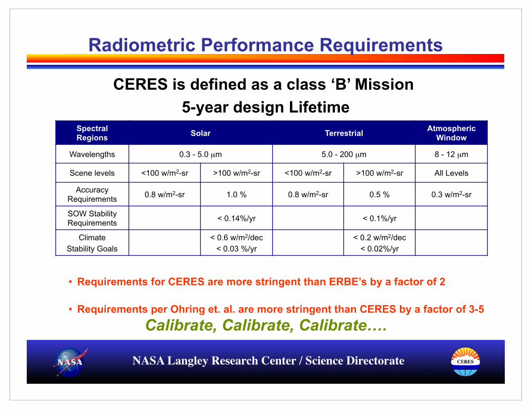
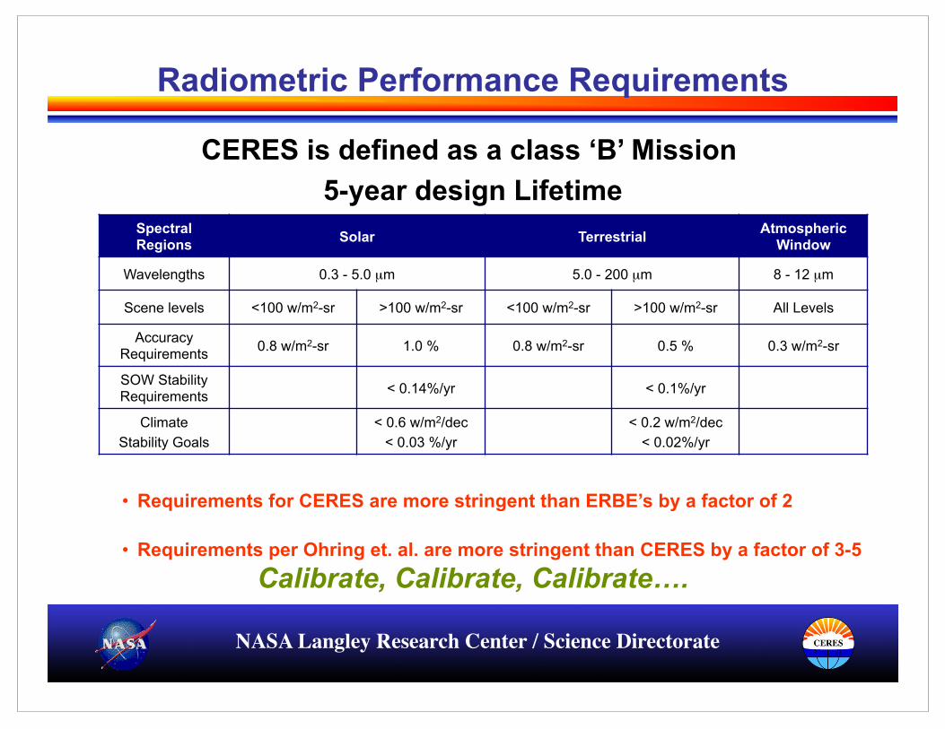
•! Requirements for CERES are more stringent than ERBE’s by a factor of 2
•! Requirements per Ohring et. al. are more stringent than CERES by a factor of 3-5
Spectral Regions
Solar Terrestrial Atmospheric
Window
Wavelengths 0.3 - 5.0 µm 5.0 - 200 µm 8 - 12 µm
Scene levels <100 w/m2-sr >100 w/m2-sr <100 w/m2-sr >100 w/m2-sr All Levels
Accuracy Requirements
0.8 w/m2-sr 1.0 % 0.8 w/m2-sr 0.5 % 0.3 w/m2-sr
SOW Stability Requirements
< 0.14%/yr < 0.1%/yr
Climate
Stability Goals
< 0.6 w/m2/dec
< 0.03 %/yr
< 0.2 w/m2/dec
< 0.02%/yr
Radiometric Performance Requirements
CERES is defined as a class ‘B’ Mission
5-year design Lifetime!
Calibrate, Calibrate, Calibrate….

NASA Langley Research Center / Science Directorate!
Why is CERES Climate Quality Calibration so difficult?!
A question of time scales, experience and balancing accuracy with providing data products to the community.
- Calibrated Radiances have been released on ~6 month centers - 6 months is just a blink of an eye when analyzing long term trends…
Same time scale as phenomena which influence instrument response - Beta Angle - Earth Sun Distance - Orbital shifts - Instrument Operational modes (I.e RAPS vs. Xtrack)
Design weaknesses and failures in onboard calibration hardware - full spectral range of observations not covered by cal subsystems
Complicates separation of instrument ‘artifacts’ from natural variability.
Edition3 reprocessing of the first 10 years of radiances allows a more rigorous identification and separation of instrument artifacts and climate signals.

NASA Langley Research Center / Science Directorate!
Spacecraft Instruments Launch Science Initiation
Collected Data
(Months)
TRMM PFM 11/97 1/98 9
Terra FM1, FM2 12/99 3/00 122 +
Aqua FM3, FM4 5/02 6/02 95 +
NPP FM5 9/11 - -
JPSS - 1 FM6 2016 - -
JPSS - 2 ERBS 2019 - -
39 + Instrument Years of Data!
Enabling Climate Data Record Continuity
CERES Flight Schedule

NASA Langley Research Center / Science Directorate!
97 98 99 00 01 02 03 04 05 06 07 08 09 10 11 12 13 14 15 16 17 18 19 20 21
Missions with ERB Observations
PFM FM-1,2 FM-5 FM-6 ERBS Sensors:
CY:
FM-6
CERES Follow-on +
CERES Flight Schedule
FM-5
Initial Studies/Reqmts Development
Sensor Fab, Assembly, Test
Spacecraft I&T
Launch Readiness Window
Nominal Mission Lifetime
Operational Lifetime
TRMM (11/97)
Terra (12/99)
Aqua (5/02)
NPP (10/11)
JPSS-1 (11/16)
JPSS-2 (11/19)
FM-3,4
Enabling Climate Data Record Continuity

NASA Langley Research Center / Science Directorate!
Enabling Climate Data Record Continuity
Agency Roles and Responsibilities
Mission Instruments
Responsible Agency
($$ in budget) Implementation
Hardware Science, Data
Processing Hardware
Science, Data
Processing
EOS PFM-FM4 NASA NASA NASA
Procurement
NASA
Science Team
NPP FM5 NASA/NOAA NASA NASA
Procurement
NASA
Science Team
JPSS-1 FM6 NOAA TBR NASA
Procurement TBR
JPSS-2 CERES
follow-on NOAA TBR
NASA Procurement
TBR

NASA Langley Research Center / Science Directorate!
EOS Status

NASA Langley Research Center / Science Directorate!
CERES/EOS Operational History
With the exception of the SW channel on the CERES/Aqua FM-4 Instrument,
the CERES Terra/Aqua instruments are functioning nominally…
Spacecraft Instruments Launch Science Initiation
Collected Data
(Months)
TRMM PFM 11/97 1/98 9
Terra FM1, FM2 12/99 3/00 122 +
Aqua FM3, FM4 5/02 6/02 95 +
NPP FM5 9/11 - -
JPSS - 1 FM6 2015 - -
JPSS - 2 ERBS - -
37 + Instrument Years of Data!

NASA Langley Research Center / Science Directorate!
Terra/Aqua Instrument and ERBE-Like Availability!
Spacecraft Product Version Available Months Processed
TRMM BDS Edition1 Yes 1/98 - 8/98 , 3/00
ERBE-Like Edition1 Yes 1/98 - 8/98 , 3/00
Edition2 Yes 1/98 - 8/98 , 3/00
Terra BDS Edition1 Yes 2/00 - present
Edition2 Yes 2/00 – 8/10
Editon3 Yes 2/00 – 3/09
ERBE-like Edition1 Yes 2/00 - present
Edition2 Yes 2/00 – 8/10
Editon3 In Production 2/00 – 3/09
Aqua BDS Edition1 Yes 6/02 - present
Edition2 Yes 6/02 – 8/10
Editon3 ASDC Testing 2/00 – 3/09
ERBE-like Edition1 Yes 6/02 - present
Edition2 Yes 6/02 – 8/10
Editon3 ASDC Testing 2/00 – 3/09
Note: Red text indicates months are in final validation prior to public release.!

NASA Langley Research Center / Science Directorate!
Cal/Val Protocol Overviews!
Edition1_CV - Static Algorithms and coefficients - baseline product used in cal/val protocol
Edition2 - Utilizes temporally varying coefficients to correct for traceable radiometric drift. All spectral changes are broadband and ‘gray’.
Edition3 - Accounts for temporally varying spectral artifacts in the SW and LW measurements.
User Applied Revisions - Advance capabilities to the users prior to the release of the next Edition.
Edition2 products lag Edition1 by a minimum of 6-12 months

NASA Langley Research Center / Science Directorate!
CERES Calibration Input Parameters
Category Parameter Edition1 Edition2 Edition3
Radiometry Gain Static Piecewise linear ~ 6 month intervals
Continuous, based upon ICS
Spectral Response Static Gray Changes Wavelength Dependent Changes
Scan Dependent Offsets Ground Ground Terra - DSCAL Aqua -TBD
2nd Time Constant Ground Ground Flight
Thermal Correction Common Correction Common Correction Instrument Specific
IBB PRT Coefficients Static Static Static
Pointing Alignment Static Static Static
Gimbal Offsets Static Static Static
Time Response Static Static Static
Coefficients updated in Cal/Val Protocols Traceability Matrix

NASA Langley Research Center / Science Directorate!
FM-5 Status
NASA Langley Research Center / Science Directorate!
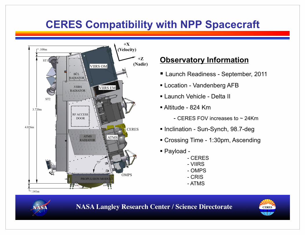
CERES Compatibility with NPP Spacecraft
4.026m
3.720m
.108m
.141m
VIIRS
RADIATOR
ATMS
RADIATOR
VIIRS OM
ATMS
OMPS PROPULSION MODULE
ST1
ST2
75°
+X (Velocity)
+Z (Nadir)
BCL
RADIATOR
VIIRS EM
SSW2 SSW1
RF ACCESS
DOOR
CERES
Observatory Information
!! Launch Readiness - September, 2011
!! Location - Vandenberg AFB
!! Launch Vehicle - Delta II
!! Altitude - 824 Km
-! CERES FOV increases to ~ 24Km
!! Inclination - Sun-Synch, 98.7-deg
!! Crossing Time - 1:30pm, Ascending
!! Payload - -! CERES -! VIIRS -! OMPS -! CRIS -! ATMS

NASA Langley Research Center / Science Directorate!
CERES FM5 Hardware Status & Near-Term Activities
•! Fabrication, Assembly and Test Program is complete
•! Ground Calibration was most extensive to date in the CERES Program
–! 33 days under continuous vacuum
–! 6 supplemental tests beyond legacy procedure
–! NGST Test Team did an outstanding job…
•! System Acceptance Review 10/30 at NGST
•! Shipped to BATC on 11/2/09
•! Mechanical/Electrical Integration to NPP spacecraft completed 11/11/08 –! P12 Connector Replacement completed 1/27/09
•! System End-to-End Test completed 2/12-26/09
•! Ground Calibration TIM at NGST 3/26/09
•! Observatory Pre-environmental Test Readiness Review 9/20-21/10
•! Spacecraft Environmental Campaign 11/10-4/11
•! NPP ‘Official’ Launch Readiness Date is currently September, 2011 –! Initial NPP launch date was mid-2006
NASA Langley Research Center / Science Directorate!
FM-6 Status

NASA Langley Research Center / Science Directorate!
CERES FM6 Status & Near-Term Activities
•! Project received ~$5M for FM6 in CY08
•! Allowed for enhanced study phase only, start 11/08
–! review of legacy processes and procedures
–! Initial Spacecraft/sensor ICD development
–! Upgraded on-board calibration equipment design studies (ASIC3 Report)
•! Long Lead item procurements authorized 3/09
•! Contract negotiations completed 4/23/09
•! Key Milestone Dates (Preliminary)
–! Authority To Proceed – 5/1/09
–! Systems Readiness Review – 9/22/09
–! Delta Preliminary Design Review – January 2010
–! Delta Critical Design Review – September 28, 2010
–! Delivery – July 2012
–! Launch Readiness Date of Jan, 2015
–! Launch Date of Oct. 2016

NASA Langley Research Center / Science Directorate!
!"#$#%&'()*$+&*&,-./#,(0-".-&12(-#(3''"&%%(
456507580(4.+9:"./#,(0;:%2%-&*(<&%91,(
=&.>,&%%&%(.,'(?.9+;"&%(

NASA Langley Research Center / Science Directorate!
Recommended Improvements to CERES FM6
Capability PFM through FM-5 FM-6 Rationale for Change
Longwave /
Window Channel 8 - 12 micron 5 – 100 Micron
-! Risk Reduction
-! Improved 3-Channel Consistency Test
New Solar
Calibration MAM
Surface Reflectance Instability
-! Improved Coating
-! Enhanced Screening
- Stability Monitor
Need for functional stability monitor
Shortwave Internal
Cal Source
Upgrade
- Lack of sensitivity in blue region
- Unstable Reference Detector
-! Addition of source in blue region -! New Reference Detector identified
Requirement for ability to detect changes in spectral response
function.
Blackbody
Temperature
Range
Minimum internal blackbody set point
temperature too warm (290-320 K).
Lower Internal blackbody set point temperatures to be
consistent with Earth Temp’s (270-320 K)
Eliminates second-order effects caused by
blackbody being warmer than Earth
Green : Funding not currently available

NASA Langley Research Center / Science Directorate!
Both the MAM improvement (with reference detector) and SWICS improvement (blue source) are required to meet performance requirements:
Impact
This will provide a robust onboard calibration system that can:
i)! identify any changes in instrument gain;
ii)! identify changes in the shortwave channel separately from the shortwave part of the total channel;
iii)! provide a direct measure in the blue region to detect and correct for spectral darkening associated with molecular contamination;
iv)! be able to correct for spectral degradation even if either the MAM or associated reference detector failed to meet the expected performance.
Conclusion
Recommended improvements provide the minimal level of redundancy that will
ensure the CERES FM6 observational requirements are met and rigorously verified, given the expected operational environment.
NASA Recommended Implementation

NASA Langley Research Center / Science Directorate!
No funding is available to implement either the MAM improvement (with reference detector) or SWICS improvement (blue source):
Impact
!! There will be no direct means of quantifying and correcting for expected measurement loss of sensitivity with time in the Reflected Solar Bands.
Conclusion
!! High probability that CERES FM6 Observational requirements will not be met.
Result
CERES Project Office has no choice but to move forward with the legacy EOS on-board SW calibration sources as the baseline design for FM-6.
Current Implementation : Funding Limited

NASA Langley Research Center / Science Directorate!
CERES Follow-on status
Currently known as ‘Earth Radiation Budget Sensor’, or ERBS
NASA Langley Research Center / Science Directorate!
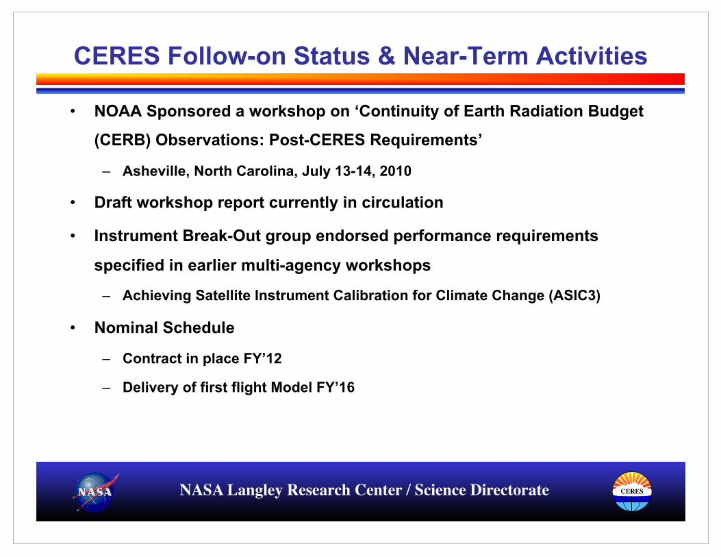
CERES Follow-on Status & Near-Term Activities
•! NOAA Sponsored a workshop on ‘Continuity of Earth Radiation Budget
(CERB) Observations: Post-CERES Requirements’
–! Asheville, North Carolina, July 13-14, 2010
•! Draft workshop report currently in circulation
•! Instrument Break-Out group endorsed performance requirements
specified in earlier multi-agency workshops
–! Achieving Satellite Instrument Calibration for Climate Change (ASIC3)
•! Nominal Schedule
–! Contract in place FY’12
–! Delivery of first flight Model FY’16

NASA Langley Research Center / Science Directorate!
•! Proposed requirements for ERBS are more stringent than CERES by a factor of 2-5
Proposed ERBS Radiometric Performance Requirements
CERES vs. ERBS
Calibrate, Calibrate, Calibrate….
Parameter Spectral
Band CERES ERBS
Accuracy (%/decade)
SW 2.0 1.0
TOT 1.0 0.5
LW 1.0 0.5
Stability (%/decade)
SW 1.4 0.3
TOT 1.0 0.3
LW 1.0 0.3

NASA Langley Research Center / Science Directorate!
Summary

NASA Langley Research Center / Science Directorate!
BACK-UP SLIDES
NASA Langley Research Center / Science Directorate!
•! Requirements for CERES are more stringent than ERBE’s by a factor of 2
•! Requirements per Ohring et. al. are more stringent than CERES by a factor of 3-5
Spectral Regions
Solar Terrestrial Atmospheric
Window
Wavelengths 0.3 - 5.0 µm 5.0 - 200 µm 8 - 12 µm
Scene levels <100 w/m2-sr >100 w/m2-sr <100 w/m2-sr >100 w/m2-sr All Levels
Accuracy Requirements
0.8 w/m2-sr 1.0 % 0.8 w/m2-sr 0.5 % 0.3 w/m2-sr
SOW Stability Requirements
< 0.14%/yr < 0.1%/yr
Climate
Stability Goals
< 0.6 w/m2/dec
< 0.03 %/yr
< 0.2 w/m2/dec
< 0.02%/yr
Radiometric Performance Requirements
CERES is defined as a class ‘B’ Mission
5-year design Lifetime!
Calibrate, Calibrate, Calibrate….

NASA Langley Research Center / Science Directorate!
EOS Calibration Report
NASA Langley Research Center / Science Directorate!
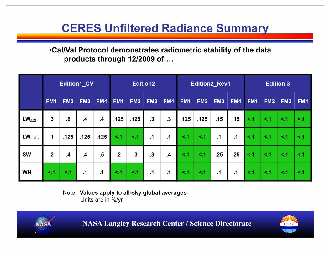
Note: Values apply to all-sky global averages Units are in %/yr!
Edition1_CV Edition2 Edition2_Rev1 Edition 3
FM1 FM2 FM3 FM4 FM1 FM2 FM3 FM4 FM1 FM2 FM3 FM4 FM1 FM2 FM3 FM4
LWday .3 .6 .4 .4 .125 .125 .3 .3 .125 .125 .15 .15 <.1 <.1 <.1 <.1
LWnight .1 .125 .125 .125 <.1 <.1 .1 .1 <.1 <.1 .1 .1 <.1 <.1 <.1 <.1
SW .2 .4 .4 .5 .2 .3 .3 .4 <.1 <.1 .25 .25 <.1 <.1 <.1 <.1
WN <.1 <.1 .1 .1 <.1 <.1 .1 .1 <.1 <.1 .1 .1 <.1 <.1 <.1 <.1
•!Cal/Val Protocol demonstrates radiometric stability of the data products through 12/2009 of….
CERES Unfiltered Radiance Summary

NASA Langley Research Center / Science Directorate!
CERES Edition2 Calibration Summary
Residual calibration errors in CERES Edition2 data products are
dominated by spectral degradation of sensor optics in the reflected solar bands. (SW and SW/TOT)
This results in
-! Artificial decreasing trend in the reflected solar measurements
-! User Applied Revision developed to correct All-sky and Clear Ocean Scenes
-! Divergence between daytime and nighttime OLR records with time.
•! LWday = Total - Shortwave
•! LWnight = Total
Occurs on all four CERES EOS sensors to varying degrees
Highly correlated to several factors -! Operational Mode -! Solar Cycle -! Atomic Oxygen fluence levels
Instability of the Solar Diffusers (MAM’s) and lack of adequate Spectral coverage in
the onboard SW sources greatly complicates the characterization and removal of
this phenomena

NASA Langley Research Center / Science Directorate!
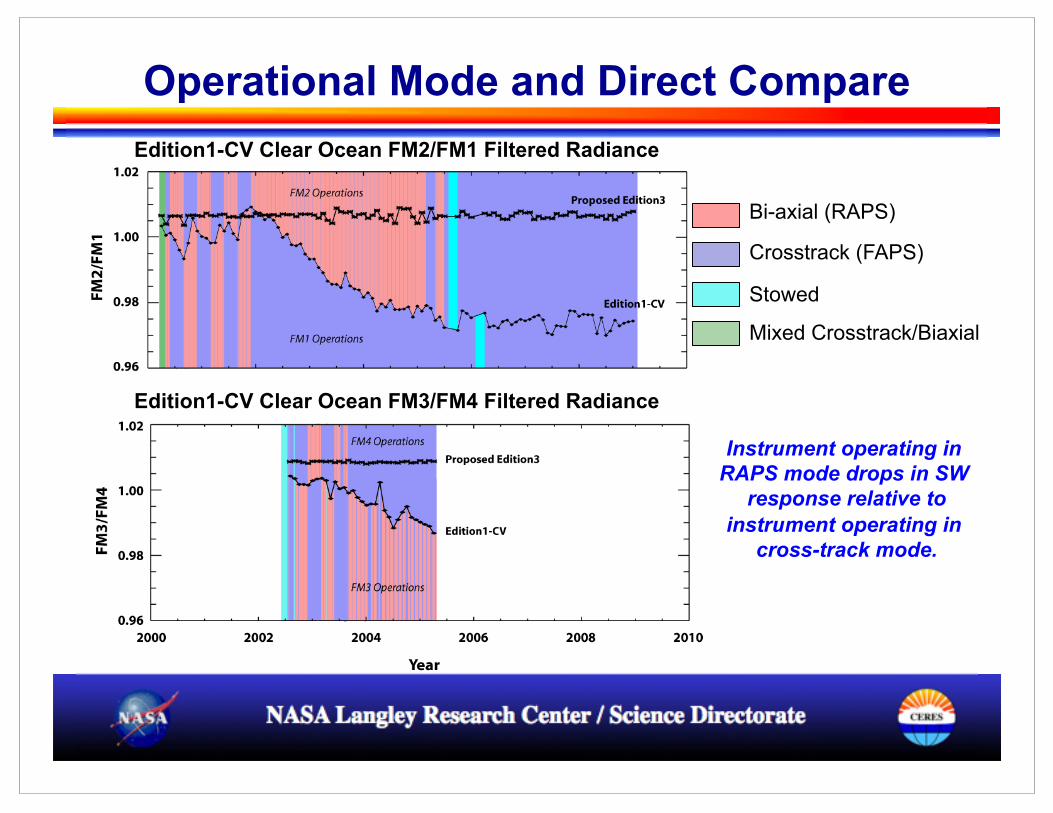
FM1 Operational Mode
FM2 Operational Mode
Bi-axial (RAPS)
Crosstrack (FAPS)
Stowed
Mixed Crosstrack/Biaxial
Operational Mode and Direct Compare
Edition1-CV Clear Ocean FM2/FM1 Filtered Radiance
Instrument operating in RAPS mode
drops in SW response relative to
instrument operating in cross-track mode.

NASA Langley Research Center / Science Directorate!
OLR Day Night Difference Trends : Tropical Mean
Edition1-CV
Edition2
~1.0% per decade (Terra) Ra
dia
nc
e R
ad
ian
ce
Data Set
•! LW Unfiltered Radiance
•! Nadir
•! 20N - 20S
•! Tropical Ocean
•! All-Sky
NASA Langley Research Center / Science Directorate!
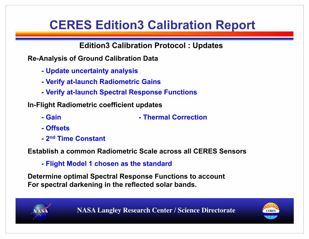
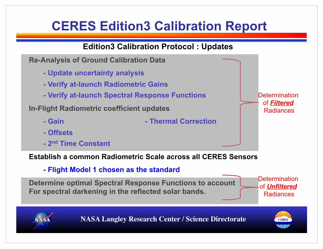
CERES Edition3 Calibration Report
Edition3 Calibration Protocol : Updates
Re-Analysis of Ground Calibration Data
- Update uncertainty analysis
- Verify at-launch Radiometric Gains
- Verify at-launch Spectral Response Functions
In-Flight Radiometric coefficient updates
- Gain - Thermal Correction
- Offsets
- 2nd Time Constant
Establish a common Radiometric Scale across all CERES Sensors
- Flight Model 1 chosen as the standard
Determine optimal Spectral Response Functions to account For spectral darkening in the reflected solar bands.

NASA Langley Research Center / Science Directorate!
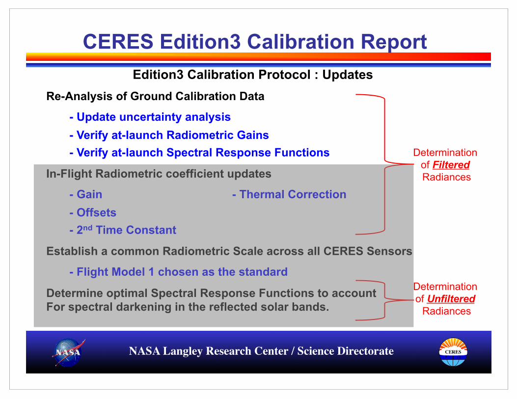
CERES Edition3 Calibration Report
Edition3 Calibration Protocol : Updates
Re-Analysis of Ground Calibration Data
- Update uncertainty analysis
- Verify at-launch Radiometric Gains
- Verify at-launch Spectral Response Functions
In-Flight Radiometric coefficient updates
- Gain - Thermal Correction
- Offsets
- 2nd Time Constant
Establish a common Radiometric Scale across all CERES Sensors
- Flight Model 1 chosen as the standard
Determine optimal Spectral Response Functions to account For spectral darkening in the reflected solar bands.
Determination of Filtered Radiances
Determination of Unfiltered
Radiances
NASA Langley Research Center / Science Directorate!
CERES Edition3 Calibration Report
Edition3 Calibration Protocol : Updates
Re-Analysis of Ground Calibration Data
- Update uncertainty analysis
- Verify at-launch Radiometric Gains
- Verify at-launch Spectral Response Functions
In-Flight Radiometric coefficient updates
- Gain - Thermal Correction
- Offsets
- 2nd Time Constant
Establish a common Radiometric Scale across all CERES Sensors
- Flight Model 1 chosen as the standard
Determine optimal Spectral Response Functions to account For spectral darkening in the reflected solar bands.
Determination of Filtered Radiances
Determination of Unfiltered
Radiances

NASA Langley Research Center / Science Directorate!
CERES : At-Launch Uncertainty Analysis
Introducing wavelength dependent uncertainties to classify confidence as a function of scene type
Lead : Nathan Smith
NASA Langley Research Center / Science Directorate!
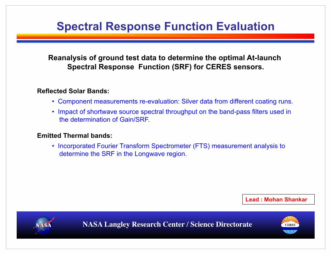
Spectral Response Function Evaluation
Reanalysis of ground test data to determine the optimal At-launch Spectral Response Function (SRF) for CERES sensors.
Reflected Solar Bands:
•! Component measurements re-evaluation: Silver data from different coating runs.
•! Impact of shortwave source spectral throughput on the band-pass filters used in the determination of Gain/SRF.
Emitted Thermal bands:
•! Incorporated Fourier Transform Spectrometer (FTS) measurement analysis to determine the SRF in the Longwave region.
Lead : Mohan Shankar

NASA Langley Research Center / Science Directorate!
Wavelength (microns)
Th
rou
gh
pu
t (-
) T
hro
ug
hp
ut
(-)
Total Channel Spectral Response Functions

NASA Langley Research Center / Science Directorate!
TERRA Radiance Comparison : March 2000
ALL SKY Global Flux Results for March 2000
FM1 FM2 FM1-FM2
Edition3 Wm-2
Edition2 Wm-2
Ed3-Ed2 Edition3
Wm-2 Edition2
Wm-2 Ed3–Ed2
Edition2 Edition3
LWday 230.74 228.91 0.80% 230.74 229.91 0.36% -0.43% 0%
LWnite 224.99 224.15 0.37% 224.36 223.82 0.24% 0.15% 0.28%
SW 255.96 255.84 0.05% 255.89 255.70 0.07% 0.03% 0.05%
Edition2 and Edition3 Spectral Response Function
Notes : ERBE-Like ES-8 NADIR data Matched Footprints Each sensor on native radiometric scale Ed3 or Ed2 Gains New BOM SRF Ground to Flight Shift Edition3 Thermal
Lead : Dale Walikainen

NASA Langley Research Center / Science Directorate!
CERES Edition3 Calibration Report
Edition3 Calibration Protocol : Updates
Re-Analysis of Ground Calibration Data
- Update uncertainty analysis
- Verify at-launch Radiometric Gains
- Verify at-launch Spectral Response Functions
In-Flight Radiometric coefficient updates
- Gain - Thermal Correction
- Offsets
- 2nd Time Constant
Establish a common Radiometric Scale across all CERES Sensors
- Flight Model 1 chosen as the standard
Determine optimal Spectral Response Functions to account For spectral darkening in the reflected solar bands.
Determination of Filtered Radiances
Determination of Unfiltered
Radiances

NASA Langley Research Center / Science Directorate!
Ground to Flight Shift Analysis for Edition3
IBB and SWICS Pre-Launch and Post-Launch calibration data re-evaluated to quantify ground to flight changes in sensor gains.
Lead : Susan Thomas
Total Window Shortwave
FM1 -0.13% 0.40% -0.50%
FM2 -0.21% 1.61% -0.01%
FM3 0.04% 0.25% 8.00%
FM4 -0.62% 0.37% -1.96%
Ground to Flight change in sensor responsivity :
Note: Terra shifts incorporated in Edition3 Aqua shifts included in Edition1-CV
NASA Langley Research Center / Science Directorate!
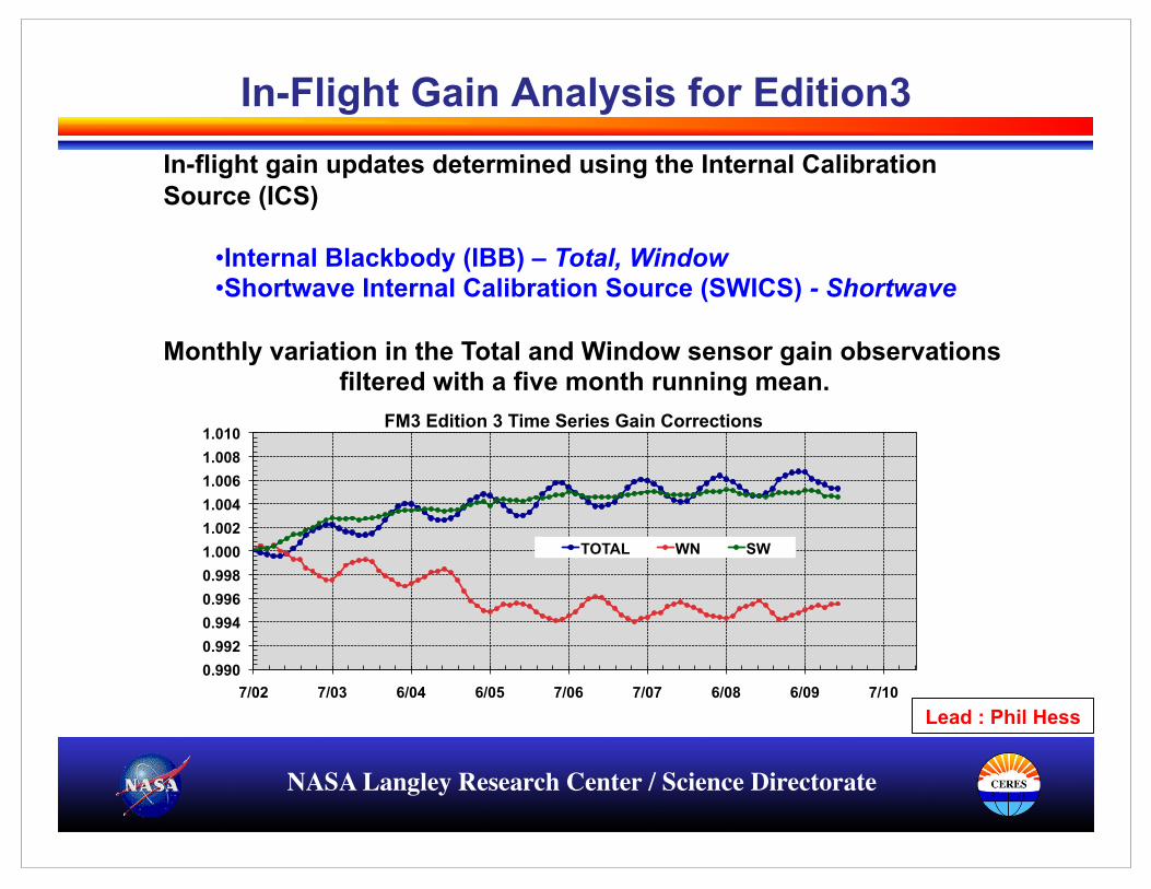
In-Flight Gain Analysis for Edition3
In-flight gain updates determined using the Internal Calibration Source (ICS)
•!Internal Blackbody (IBB) – Total, Window •!Shortwave Internal Calibration Source (SWICS) - Shortwave
Monthly variation in the Total and Window sensor gain observations filtered with a five month running mean.
0.990
0.992
0.994
0.996
0.998
1.000
1.002
1.004
1.006
1.008
1.010
7/02 7/03 6/04 6/05 7/06 7/07 6/08 6/09 7/10
FM3 Edition 3 Time Series Gain Corrections
TOTAL WN SW
Lead : Phil Hess

NASA Langley Research Center / Science Directorate!
Scan Angle Dependent Offset Stability Verification
A
B
C D
nadir
Space look samples:1" 60 & 600 " 660
Space look & internal calibration samples: 260 "400
Analysis of nighttime Earth viewing data combined with
Limb Darkening model, offset stability verified at the
0.05 Wm-2 level
Pattern Recognition in Reducing Bias of CERES Radiometeric Measurements; Z. Peter Szewczyk, AIAA-2008-884, 46th AIAA Aerospace Sciences Meeting and Exhibit, Reno, Nevada, Jan. 7-10, 2008
Lead : Peter Szewczyk

NASA Langley Research Center / Science Directorate!
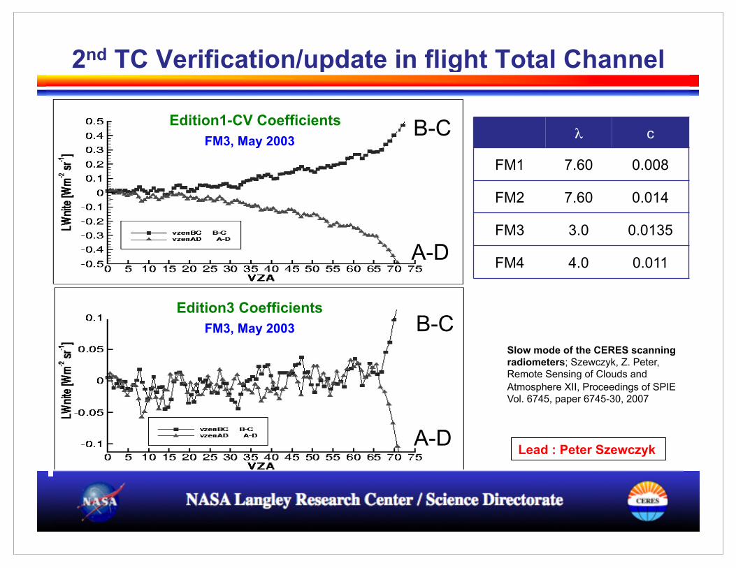
2nd TC Verification/update in flight Total Channel
•! Edition 1&2 filter parameters were determined using internal calibration data
–! analyzing the difference between calibration signal and radiometer response
•! Edition 3 filter parameters are set based on analyzing Earth viewing data
–! measurements of nightime tropical mean tropics at night for total channel (LW)
AB
CD
nadir cold to hot: A - D
hot to cold: B - C
NASA Langley Research Center / Science Directorate!
B-C
A-D
Edition1-CV Coefficients
B-C
A-D
2nd TC Verification/update in flight Total Channel
Edition3 Coefficients
Slow mode of the CERES scanning radiometers; Szewczyk, Z. Peter, Remote Sensing of Clouds and
Atmosphere XII, Proceedings of SPIE Vol. 6745, paper 6745-30, 2007
FM3, May 2003
FM3, May 2003
# c
FM1 7.60 0.008
FM2 7.60 0.014
FM3 3.0 0.0135
FM4 4.0 0.011
Lead : Peter Szewczyk
NASA Langley Research Center / Science Directorate!
CERES Edition3 Calibration Report
Edition3 Calibration Protocol : Updates
Re-Analysis of Ground Calibration Data
- Update uncertainty analysis
- Verify at-launch Radiometric Gains
- Verify at-launch Spectral Response Functions
In-Flight Radiometric coefficient updates
- Gain - Thermal Correction
- Offsets
- 2nd Time Constant
Establish a common Radiometric Scale across all CERES Sensors
- Flight Model 1 chosen as the standard
Determine optimal Spectral Response Functions to account For spectral darkening in the reflected solar bands.
Determination of Filtered Radiances
Determination of Unfiltered
Radiances

NASA Langley Research Center / Science Directorate!
Edition3 Spectral Darkening
Correction & Validation
Of
CERES Reflected Solar bands
(SW and SW/TOT channels)

NASA Langley Research Center / Science Directorate!
Part 1
SW Channel

NASA Langley Research Center / Science Directorate!
Strategy for Characterizing Spectral Degradation
•! Assumptions
!! temporal variation in FM2/FM1 SW unfiltered radiance ratio (i.e. direct nadir radiance comparison) is due to spectral degradation !! Spectral degradation occurs only on RAPS instrument
•! Compare monthly averaged spatially/temporally matched nadir FM1 and FM2 observations for specific scene types
!! Clear ocean shows largest sensitivity to RAPS spectral darkening
•! Xtrack mode sensor - unfilter with previous month’s SRF.
•! RAPs mode sensor - Retrieve optimal SRF from a set of candidate SRFs with varying degrees of spectral darkening
!! Optimal RAP SRFs ensure constant SW unfiltered FM2/FM1 radiance ratio throughout the mission.
Direct Nadir Radiance Comparison

NASA Langley Research Center / Science Directorate!
FM1 Operational Mode
FM2 Operational Mode
Bi-axial (RAPS)
Crosstrack (FAPS)
Stowed
Mixed Crosstrack/Biaxial
Operational Mode and Direct Compare
Edition1-CV Clear Ocean FM2/FM1 Filtered Radiance
Instrument operating in RAPS mode
drops in SW response relative to
instrument operating in cross-track mode.

NASA Langley Research Center / Science Directorate!
Candidate Spectral Darkening Curves
Sp
ectr
al D
eg
rad
ati
on
(-)
Wavelength (microns)
•! Functional form similar to that observed in other missions (e.g. GOME, LDEF)
•! Spectral darkening increases with shorter wavelengths. •! Plot shown is only a subset of the 53 “candidate” curves.

NASA Langley Research Center / Science Directorate!
% L
oss in
Bro
ad
ban
d T
hro
ug
hp
ut
Impact to Observations of Typical Scenes

NASA Langley Research Center / Science Directorate!
Retrieved SW Channel Degradation Parameter Alpha
Terra
Direct Compare Constraint Method Clear Ocean Allsky Ocean

NASA Langley Research Center / Science Directorate!
Retrieved SW Channel Degradation Parameter Alpha
Aqua
Direct Compare Constraint Method Clear Ocean Allsky Ocean

NASA Langley Research Center / Science Directorate!
Alpha Retrieval Results : FM1 and FM2 SW Channels

NASA Langley Research Center / Science Directorate!
Alpha Retrieval Results : FM3 and FM4 SW Channels
NASA Langley Research Center / Science Directorate!
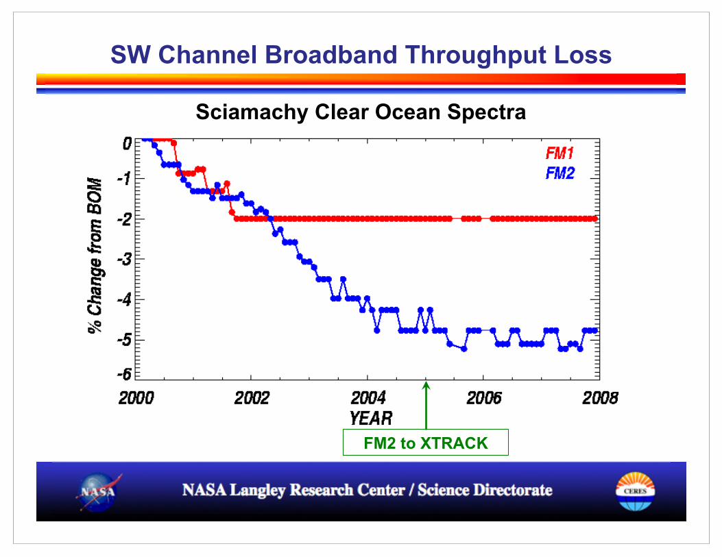
SW Channel Broadband Throughput Loss
FM2 to XTRACK
Sciamachy Clear Ocean Spectra
NASA Langley Research Center / Science Directorate!
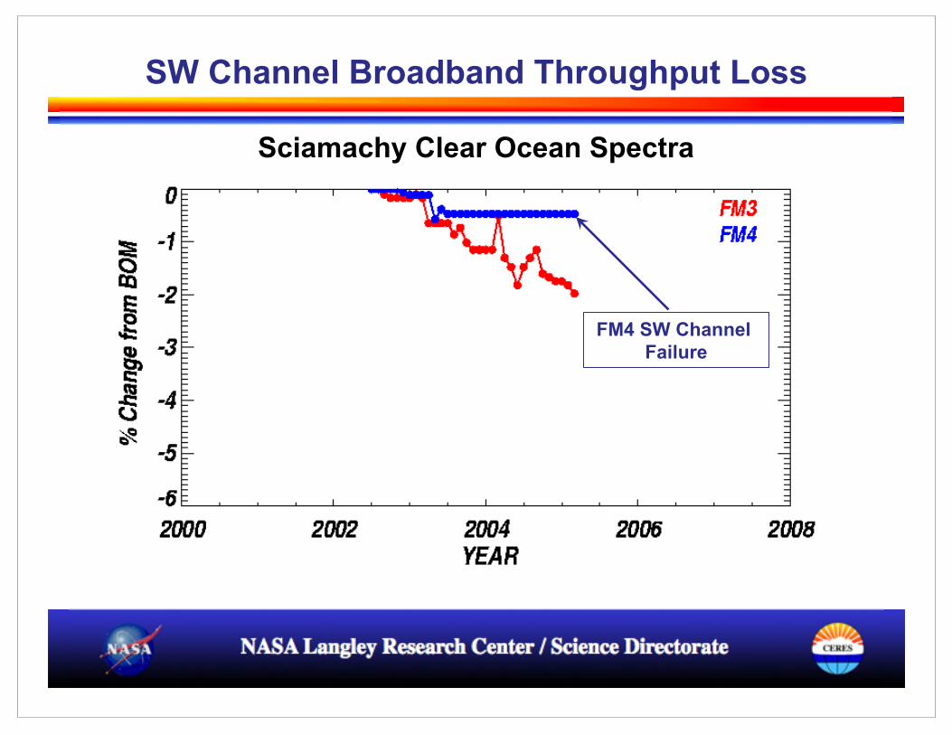
SW Channel Broadband Throughput Loss
FM4 SW Channel Failure
Sciamachy Clear Ocean Spectra

NASA Langley Research Center / Science Directorate!
FM1 Operational Mode
FM2 Operational Mode
Bi-axial (RAPS)
Crosstrack (FAPS)
Stowed
Operational Mode and Direct Compare
Instrument operating in
RAPS mode drops in SW
response relative to
instrument operating in
cross-track mode.
Edition1-CV Clear Ocean FM2/FM1 Filtered Radiance
Edition1-CV Clear Ocean FM3/FM4 Filtered Radiance
Bi-axial (RAPS)
Crosstrack (FAPS)
Stowed
Mixed Crosstrack/Biaxial
FM2 Operational Mode
FM1 Operational Mode
NASA Langley Research Center / Science Directorate!
Operational Mode and Direct Compare
Instrument operating in
RAPS mode drops in SW
response relative to
instrument operating in
cross-track mode.
Edition1-CV Clear Ocean FM2/FM1 Filtered Radiance
Edition1-CV Clear Ocean FM3/FM4 Filtered Radiance
Bi-axial (RAPS)
Crosstrack (FAPS)
Stowed
Mixed Crosstrack/Biaxial
Edition1-CV Clear Ocean FM3/FM4 Filtered Radiance

NASA Langley Research Center / Science Directorate!
FM2/FM1 SW Unfiltered Radiance Ratio for Clear Sky Scenes Scenes

NASA Langley Research Center / Science Directorate!
FM2/FM1 SW Unfiltered Radiance Ratio for All Sky Scenes

NASA Langley Research Center / Science Directorate!
FM3/FM4 SW Unfiltered Radiance Ratio for Clear Sky Scenes
NASA Langley Research Center / Science Directorate!
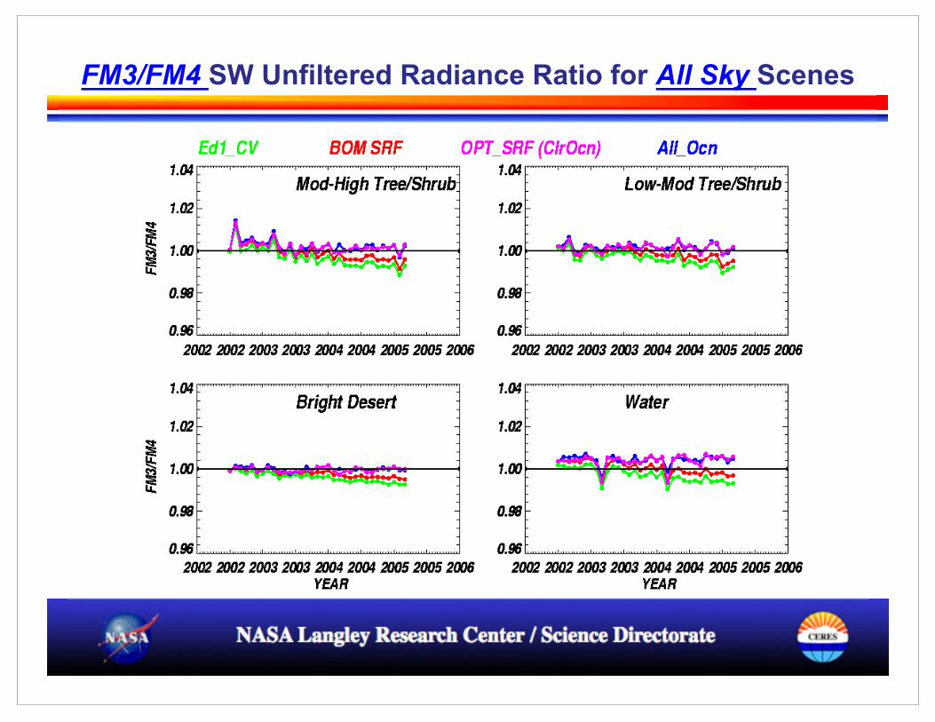
FM3/FM4 SW Unfiltered Radiance Ratio for All Sky Scenes

NASA Langley Research Center / Science Directorate!
Edition3 Validation : CERES to SeaWiFS
NASA Langley Research Center / Science Directorate!
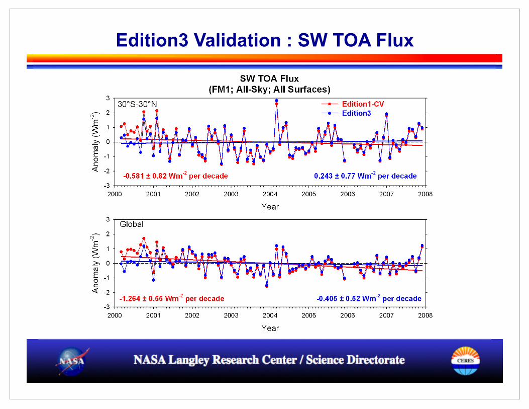
Edition3 Validation : SW TOA Flux

NASA Langley Research Center / Science Directorate!
Edition3 Validation : SW TOA Flux

NASA Langley Research Center / Science Directorate!
Part 2
SW Portion of Total Channel
or
Daytime LW Fluxes

NASA Langley Research Center / Science Directorate!
LW Day Night Difference Trends
LWday = Total – Shortwave
LWday = LW/TOT + SW/TOT – Shortwave
LWnight = LW/Total
•! Apply Total, WN and SW gains.
•! Apply Optimal SW channel SRF’s
•! Select Total SRF from a “candidate” set of SRFs that constrains the OLR Daytime minus Nightime difference to the trend of the WN channel Daytime minus Nightime observations.
•! WN channel Daytime minus Nightime difference is robust
!! Calibration stability over an orbital cycle !! As a proxy for the broadband OLR Day Night difference trends
!! Verified by comparison to AIRs

NASA Langley Research Center / Science Directorate!
OLR Day Night Difference Trends : Tropical Mean
Edition1-CV
Edition2
~1.0% per decade (Terra) Ra
dia
nc
e R
ad
ian
ce
Data Set
•! LW Unfiltered Radiance
•! Nadir
•! 20N - 20S
•! Tropical Ocean
•! All-Sky
NASA Langley Research Center / Science Directorate!
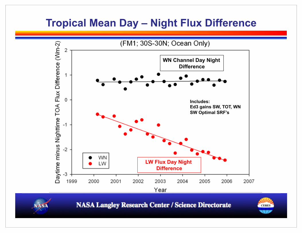
Tropical Mean Day – Night Flux Difference
WN Channel Day Night Difference
LW Flux Day Night Difference
Includes: Ed3 gains SW, TOT, WN
SW Optimal SRF’s

NASA Langley Research Center / Science Directorate!
Zonal Averages of Unfiltered Radiances All-Sky Ocean (30S – 30N), FM1
Includes: Ed3 gains SW, TOT, WN
SW Optimal SRF’s
Establishing a Constraint for LW Fluxes
Daytime minus Nighttime WN
Daytim
e m
inus N
ighttim
e L
W
March 2000

NASA Langley Research Center / Science Directorate!
Zonal Averages of Unfiltered Radiances All-Sky Ocean (30S – 30N), FM1
Includes: Ed3 gains SW, TOT, WN
SW Optimal SRF’s
Establishing a Constraint for LW Fluxes
March 2000 March 2005
Daytime minus Nighttime WN
Daytim
e m
inus N
ighttim
e L
W

NASA Langley Research Center / Science Directorate!
FM1 Zonal Averages of Unfiltered Radiances for Ocean (30S – 30N)
March 2000 $ = 6.9
$ = 7.2 $ = 7.4
$ = 7.5 $ = 8.635 $ = 11.2
March 2005
Determination of Optimal SRF for SW/TOT
Daytime minus Nighttime WN
Daytim
e m
inus N
ighttim
e L
W
Zonal Averages of Unfiltered Radiances All-Sky Ocean (30S – 30N), FM1

NASA Langley Research Center / Science Directorate!
Edition 2 & 3 Day Night Comparison : LW TOA Flux
Edition 2
Edition 3

NASA Langley Research Center / Science Directorate!
Edition3 Validation : LW TOA Flux
NASA Langley Research Center / Science Directorate!
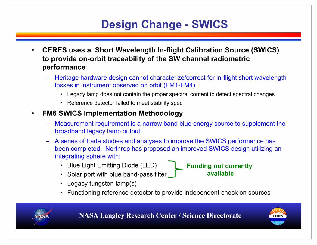
Design Change - SWICS
•! CERES uses a Short Wavelength In-flight Calibration Source (SWICS) to provide on-orbit traceability of the SW channel radiometric performance
–! Heritage hardware design cannot characterize/correct for in-flight short wavelength losses in instrument observed on orbit (FM1-FM4)
•! Legacy lamp does not contain the proper spectral content to detect spectral changes
•! Reference detector failed to meet stability spec
•! FM6 SWICS Implementation Methodology
–! Measurement requirement is a narrow band blue energy source to supplement the broadband legacy lamp output.
–! A series of trade studies and analyses to improve the SWICS performance has been completed. Northrop has proposed an improved SWICS design utilizing an integrating sphere with:
•! Blue Light Emitting Diode (LED)
•! Solar port with blue band-pass filter
•! Legacy tungsten lamp(s)
•! Functioning reference detector to provide independent check on sources
Funding not currently available

NASA Langley Research Center / Science Directorate!
•! CERES utilizes a Mirror Attenuator Mosaic (MAM) to attenuate solar irradiance allowing the sun to serve as the primary radiometric source for quantifying radiometric stability of SW and SW portion of TOT channels
–! Changes in the MAM’s effective surface reflectance of 3 to 7 percent on the CERES/EOS sensors have prevented the use of solar calibrations as a rigorous stability metric
–! Root cause of this change is two phenomena
•! Degradation of SiOx protective overcoat due to Atomic Oxygen (initial brightening)
•! Contamination on reflective surface causes decreased reflectance in blue region
•! FM6 Solar Attenuator Implementation Methodology
–! Measurement requirement is rigorous knowledge of relative changes in the MAM’s effective surface reflectance
–! Confidence in this knowledge is attained by…
•! Pre-flight verification of the hardware’s stability over the life of the mission
–! Enhanced screening and acceptance/testing program
–! Specification of Si02 (as opposed to Si0x) for protective overcoat
•! Independent measurement of MAM reflectance
–! Implementation of stable reference detector Funding not Currently
Available
!"#
Design Change – Mirror Attenuator Mosaic

NASA Langley Research Center / Science Directorate!
5."-@(6.'9.,A&%( 0=)40(6.'9.,A&%(
-! SWICS insensitive to blue end of CERES SW Spectral Response Function -! Significant contribution in this region from Earth scenes (e.g., clear ocean)
!! Lamps cannot detect changes at shorter wavelengths
B&1.A2(0=)40(4.+9:"./#,(0#;"A&(0$&A-".+(4#,-&,-(
EOS Results •! SWICS suggested SW channels were stable to 0.1% •! Earth viewing measurements showed scene-dependent decreases
!! Bluer scenes (clear ocean) had larger changes than white scenes (deep conv clouds)

NASA Langley Research Center / Science Directorate!
Legacy CERES SW Onboard Calibration Sources
Shortwave Internal Calibration Source (SWICS)
•! Evacuated Quartz tungsten lamp operated at 3 Levels (2100, 1900, 1700 K spectrums) (Insufficient Spectral Coverage) •! Silicon Photodiode (SiPd) reference detector (Failed part) •! Design specification is +-0.5% stability over 5-years •! Designed primarily to transfer SW channel Ground Cal measurements to orbit
Mirror Attenuator Mosaic (MAM)
•! Solar Diffuser plate attenuates direct solar view (~5800 K Spectrum) •! Nickel substrate with Aluminum coated spherical divots •! No independent reference detector
•! Provides a relative calibration of the Shortwave and Total channel •! Designed to provide a long-term on-orbit SW calibration source •! Solar Cal results to date are invalid due to large
drifts in MAM surface reflectances

NASA Langley Research Center / Science Directorate!
NASA Langley Research Center / Science Directorate!
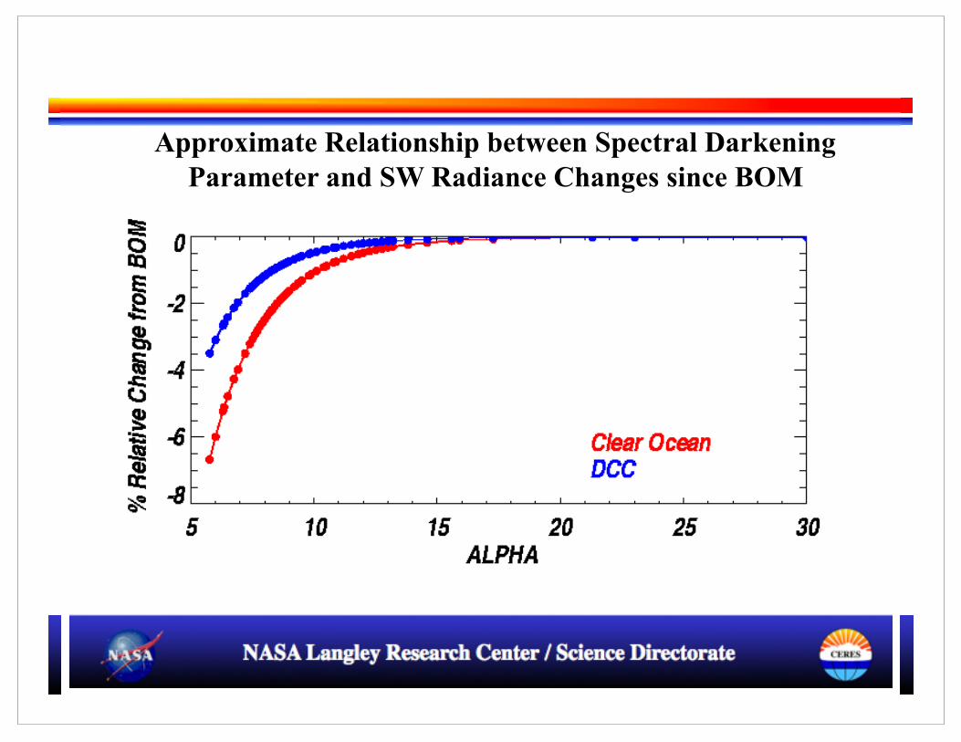
Approximate Relationship between Spectral Darkening Parameter and SW Radiance Changes since BOM

NASA Langley Research Center / Science Directorate!
FM1 Zonal Averagse (16S – 16N) for Ocean

NASA Langley Research Center / Science Directorate!
Establishing a common CERES Radiometric Scale
•! CERES measurements span 12 years (1998-2009) and are taken by 5 different instruments.
TRMM-PFM : January – August 1998, March 2000 Terra – FM1& FM2: March 2000 – Present Aqua – FM3 & FM4: July 2002 - Present
•! The same radiometric scale at the Beginning of Mission
March 2000 for Terra and July 2002 for Aqua
•! FM1 is selected to be the climate instrument: –! Produces the longest, continuous data set –! Longest in crosstrack mode of operation –! Shows the smallest spectral changes for the mission –! Shows the best consistency for the 3-channels comparison –! Shows the smallest day-night difference –! Has been used to compare with AQUA since 2002

NASA Langley Research Center / Science Directorate!
•! Requirements for CERES are more stringent than ERBE’s by a factor of 2
•! Requirements per Ohring et. al. are more stringent than CERES by a factor of 3-5
Spectral Regions
Solar Terrestrial Atmospheric
Window
Wavelengths 0.3 - 5.0 µm 5.0 - 200 µm 8 - 12 µm
Scene levels <100 w/m2-sr >100 w/m2-sr <100 w/m2-sr >100 w/m2-sr All Levels
Accuracy Requirements
0.8 w/m2-sr 1.0 % 0.8 w/m2-sr 0.5 % 0.3 w/m2-sr
SOW Stability Requirements
< 0.14%/yr < 0.1%/yr
Climate
Stability Goals
< 0.6 w/m2/dec
< 0.03 %/yr
< 0.2 w/m2/dec
< 0.02%/yr
Radiometric Performance Requirements
CERES is defined as a class ‘B’ Mission
5-year design Lifetime!
Calibrate, Calibrate, Calibrate….

NASA Langley Research Center / Science Directorate!
Path to ERB CDR Continuity Capability FM-5 FM-6 CERES Follow-on
Lineage As-Built Build to Print, with modest
upgrades, Technology
Bridge New Design
Flight Software Bug fixes, minimal
functionality improvements Bug fixes, minimal
functionality improvements Bug fixes, Full functionality
improvements
New Solar Calibration MAM
Yes + enhanced screening Yes + enhanced screening
Shortwave Internal Cal Source Upgrade*
Minimal Spectral Capability Multi-spectral Capability
Replace 8-12 µm Channel
5 - 100 Micron 5 - 100 Micron
New Detectors Yes
“10 km” FOV** Yes
Ground Calibration Re-verify sources, revisit
procedure
Re-verify sources, update procedures, upgrade data
acquisition equipment, enhanced emphasis in SOW
Re-verify sources, update procedures, upgrade data
acquisition equipment, enhanced emphasis in SOW
* Updated shortwave requirements based on improved understanding of reflected spectrum from CERES experience
** Nominal improved FOV, final requirement set as part of CERES follow-on instrument study
NASA Langley Research Center / Science Directorate!
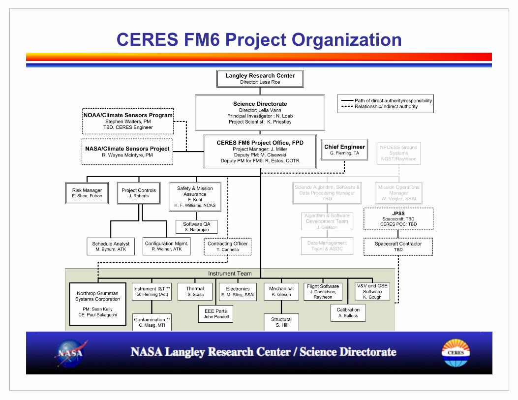
CERES FM6 Project Organization

NASA Langley Research Center / Science Directorate!

NASA Langley Research Center / Science Directorate!
- Partially redundant on-board calibrations to improve knowledge of instrument stability. Improvements are needed in broadband MAM or diffuser designs to meet the new climate stability requirements.
- More careful attention be paid to potential contamination of optical surfaces for climate instruments during ground testing, as well as improving the technologies for measuring and correcting any potential contamination.
- Flight of the CERES FM-5 instrument use only the crosstrack scan mode to avoid in-orbit contamination of the SW channel optics. We also recommend that future calibration
observatories in space be designed to explicitly account for expected in-orbit
contamination, even if its level is small.
- Future broadband instruments should examine the potential for 0.3 to 0.5 µm sources
such as small nonlinear optics lasers to explicitly monitor throughput below 0.5 µm. This issue appears to exist for all instruments measuring solar radiation with wavelengths below 0.5 µm and should be accounted for in calibration system design.
ASIC3 (2006) Workshop Recommendations

NASA Langley Research Center / Science Directorate!
LW Day Night Difference Trends
LWday = Total – Shortwave
LWnight = Total
•! Apply Total, WN and SW gains.
•! With SW spectral darkening compensated for by selected SW
optimal SRFs, select Total SRF from a “candidate” set of SRFs
that eliminates monthly offsets from Beginning of Mission
(BOM).
Use of WN channel day-night difference as a
stability metric has been independently verified by
AIRs AIRs study mitigates the
concern we had regarding broadband day
night changes which would not be observed
by our 8-12 micron window channel

NASA Langley Research Center / Science Directorate!
Strategy for Characterizing Spectral Degradation (Direct Nadir Radiance Comparison)
Need overall strategy slide
SW constrained by ClrOcn, verified with All-sky then SW/TOT constrained by Day/Night Difference WN channel AIRs confirms this.
Edition3 Studies % Spectral response degradation in SW channel - determine time-dependent “optimal” SRFs from Direct Compare approach - incorporate temporally varying SRFs in the SW measurements
(implemented in spectral unfiltering algorithm) % Divergence between daytime and nighttime OLR records with time

NASA Langley Research Center / Science Directorate!
Ground to Flight change in sensor responsivity :
Total Window Shortwave
FM1 -0.13% 0.40% -0.50%
FM2 -0.21% 1.61% -0.01%
FM3 0.04% 0.25% 8.00%
FM4 -0.62% 0.37% -1.96%
Lead : Susan Thomas
In-Flight Gain Analysis for Edition3
0.990
0.992
0.994
0.996
0.998
1.000
1.002
1.004
1.006
1.008
1.010
7/02 7/03 6/04 6/05 7/06 7/07 6/08 6/09 7/10
FM3 Edition 3 Time Series Gain Corrections
TOTAL WN SW