ceriatone 2550 · pdf file2 thank you for the purchase of your ceriatone 2550 guitar...
TRANSCRIPT

1
2550
50W Amplifier
User’s Manual
2
Thank you for the purchase of your Ceriatone 2550 guitar amplifier! Here, we hope to explain how best to use your new amp.
Table of Contents
1) About the 2550……..……...…………………………………………………………………………………………page 2 2) Quick setup……………………………………………………………………………………………………………page 3 3) Front Panel controls………………………………………………………………………………………………….page 4 4) Rear Panel controls…………………………………………………………………………………………………..page 7 5) Tube compliment and bias adjustment……………………………….……………………………………………page 9 6) Frequently Asked Questions………………………………………………………………………………………...page 13 7) Settings templates…………………………………………………………………………………………………….page 15
1) About the 2550 Our British series of amplifiers has been overwhelmingly popular, and is still the backbone of our amplifier line. The 2555 and 2550 added a classic perspective on a modern amplifier, and is renowned for it’s juicy lead tone by players ranging from Wayne Krantz to Joe Bonnamassa. The 2550 and 2555 are channel-switching heads with a shared and unique tonestack. It also features various levels of clipping to help fine-tune your tone. You’ll notice our version holds true sonically, and includes modern features including external bias measurement and adjustment, an effects loop, and an available post phase inverter master volume control. Most of all, we hope the 2550 and 2555 become an integral part of your tone equation to exhilarate your playing and music. Rock on!
- Nik Azam
3
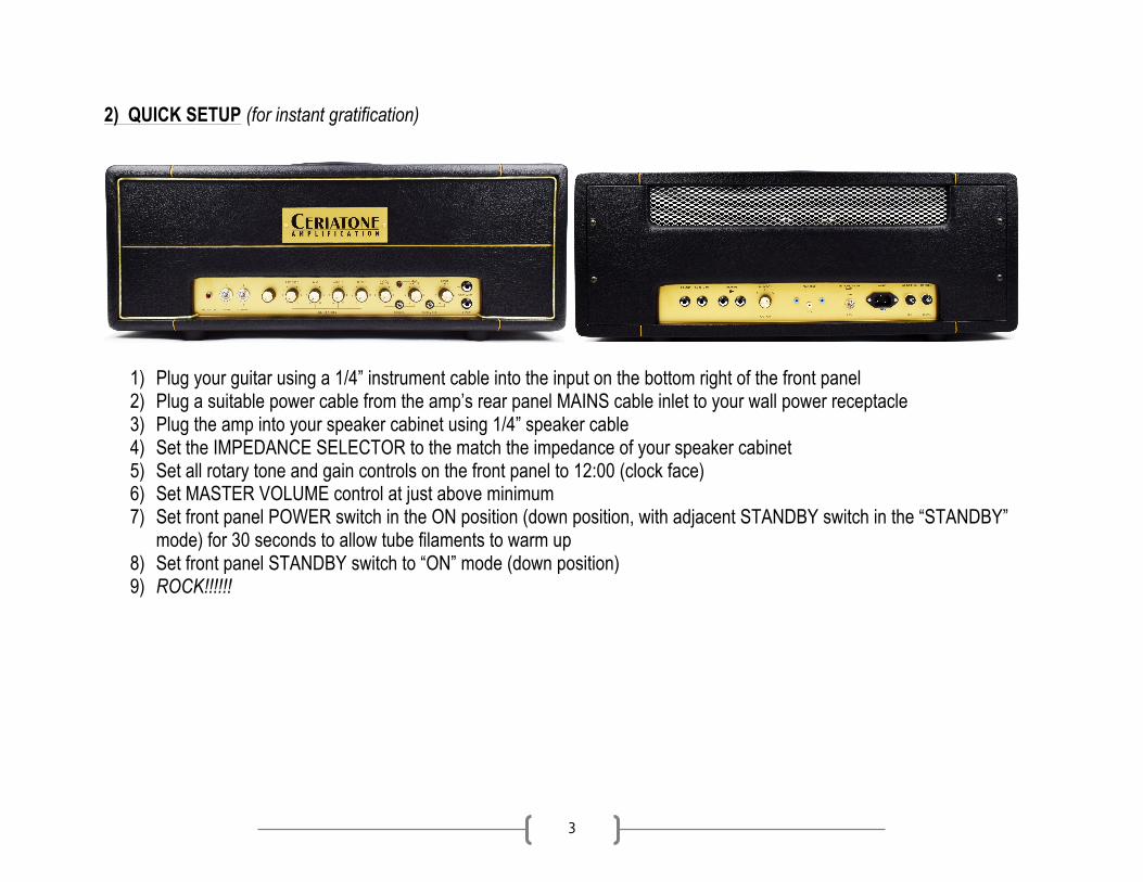
2) QUICK SETUP (for instant gratification)
1) Plug your guitar using a 1/4” instrument cable into the input on the bottom right of the front panel 2) Plug a suitable power cable from the amp’s rear panel MAINS cable inlet to your wall power receptacle 3) Plug the amp into your speaker cabinet using 1/4” speaker cable 4) Set the IMPEDANCE SELECTOR to the match the impedance of your speaker cabinet 5) Set all rotary tone and gain controls on the front panel to 12:00 (clock face) 6) Set MASTER VOLUME control at just above minimum 7) Set front panel POWER switch in the ON position (down position, with adjacent STANDBY switch in the “STANDBY”
mode) for 30 seconds to allow tube filaments to warm up 8) Set front panel STANDBY switch to “ON” mode (down position) 9) ROCK!!!!!!

4
3) FRONT PANEL CONTROLS
From left to right:
1) INDICATOR LED 2) POWER 2-way toggle switch 3) STANDBY 2-way toggle switch 4) MASTER VOLUME control (optional) 5) PRESENCE control 6) BASS control 7) MIDDLE control 8) TREBLE control 9) OUTPUT MASTER control 10) LEAD MASTER LED 11) CHANNEL 2-way toggle switch 12) LEAD MASTER control 13) RHYTHM CLIP 2-way toggle switch 14) INPUT GAIN control 15) FOOTSWITCH ¼” jack 16) INPUT ¼” instrument jack

5
INDICATOR will illuminate when the amp is powered by turning the front panel POWER toggle switch to the ON position. If INDICATOR does not turn on, check your power cable connections, and then the fuse on the rear of the unit. POWER two-way toggle switch powers the amp on and off. With the toggle switch in the DOWN (“1”) position, the amp is on. In the UP position (“O”), the amp is OFF. STANDBY applies high voltage to the vacuum tube anodes (and screen grids) during use of the amp. To ensure long tube life, first power the unit on with the STANDBY toggle switch in UP position for approximately 30 seconds. You can then switch to DOWN (“1”) to use the amp. With the toggle switch in the UP position (“0”), the amp is in STANDBY mode. In the DOWN position, the amp is in OPERATE mode MASTER VOLUME is an optional, but very popular modification we may add upon request. This is a unique master volume control that sits after the phase inverter (hence the name “post phase inverter master volume”). Unlike most master volume, this maintains the distortion, harmonic content, and feel of a cranked amplifier. If installed, use this in conjunction with the OUTPUT MASTER control to balance overall volume, feel, compression, and power amplifier breakup. PRESENCE adjusts the high frequency response of the power amplifier using negative feedback. Use this control to add sparkle and clarity to your tone. BASS adjusts low frequencies MIDRANGE adjusts the mid frequency response TREBLE adjusts the high frequency response OUTPUT MASTER adjusts the overall amplifier volume for both channels. If your amp has the PPIMV installed, use this in conjunction with it to control to balance overall volume, feel, compression, and power amplifier breakup. LEAD MASTER LED will illuminate when the LEAD channel is engaged.

6
CHANNEL 2-way toggle switches between the Clean and Lead channels of the amplifier. LEAD MASTER LED will turn on when the LEAD channel has been selected. LEAD MASTER adjusts the volume of the LEAD channel in comparison to the CLEAN channel. This is only active in the LEAD channel. It will be more effective to think of this as a channel-balancing volume control, rather than an output level control. Note it will also have an effect on distortion, too. RHYTHM CLIP 2-way toggle engages a clipping network to add modest clipping and breakup to both channels. INPUT GAIN sets the input gain and distortion levels for BOTH LEAD and RHYTHM channels. FOOTSWITCH ¼” jack is used to plug in the cable for your footswitch, and allows footswitching control between LEAD and RHYTHM channels. INPUT ¼” jack for instrument cables. Plug your guitar in here.

7
4) REAR PANEL CONTROLS
From left to right:
1) SEND ¼” instrument jack 2) RETURN ¼” instrument jack 3) SPEAKERS ¼” speaker jacks (x2) 4) IMPEDANCE SELECTOR three-way rotary selector 5) BIAS TEST probe jacks (x2) 6) COM probe jack 7) PENTODE / TRIODE HALF POWER 2-way toggle switch 8) MAINS IEC cable inlet 9) MAINS FUSE 10) HT FUSE
SEND ¼” instrument jack can be used to plug the input of your effects unit. The placement of the FX loop is somewhat non-traditional for the 2555 and 2550, and we recommend it only for use of FX units. RETURN ¼” instrument jack can be used to plug the output of your effects unit. The placement of the FX loop is somewhat non-traditional for the 2555 and 2550, and we recommend it only for use of FX units.

8
SPEAKERS ¼” speaker cable jacks. Use a ¼” speaker cable to connect your speaker cabinet to the amplifier using these jacks. If you use one speaker cabinet, either jack is acceptable. NOTE – never turn your amplifier to OPERATE mode (“1” / DOWN position on STANDBY) without connecting the amplifier to a speaker cabinet or suitable dummy load! Failing to do so may damage your amplifier! IMPEDANCE SELECTOR three-way rotary selector. Set to the position that matches the impedance of your speaker cabinet. NOTE – if you are using two speaker cabinets in parallel (ex – two 16 Ohm cabinets), set the impedance selector to half that of a single cabinet (in this case, 8 Ohms). BIAS TEST and COM multimeter probe jacks – use this for external bias current measurements (see Section 5, Page 8) PENTODE / TRIODE switches the power output of the power amp. For the 2550, half mode is approximately 25W. HALF mode configures the power tubes to run in triode operation, and this negates any need to reconfigure the IMPEDANCE SELECTOR. MAINS IEC cable inlet – plug a suitable IEC power cable into this inlet to power your amplifier MAINS FUSE slow-blow fuse – used to protect your amplifier from voltage spikes or excessive current draw. Replace only when necessary with 2A slo-blo. HT FUSE 500mA fuse – used to protect your amplifier from voltage spikes or excessive current draw. Replace only when necessary.

9
5) TUBE COMPLIMENT AND BIAS ADJUSTMENT
From left to right: V1 – 12AX7/ECC83 (Input and stage 2 gain stages – both channels) V2 – 12AX7/ECC83 (stages 3 [to FX SEND] and 4 [input from FX return]) V3 – 12AX7/ECC83 (phase inverter for power amplifier) V4-5 – EL34
BIAS ADJUSTMENT CONTROL IS INDICATED BY THE RED ARROW

10
To measure your power tube bias, carefully follow these steps with the amplifier in OPERATE, MASTER at minimum, and connected to a speaker load (not doing so may damage your amplifier!):
1) Turn on a digital multimeter (DMM), and set it to read millivolts (mV) in the 100mV range (this will vary from DMM to DMM)
2) Plug a black probe into the color-coded jack on your DMM, and do the same for a red probe 3) Insert the black probe tip into the probe jack labeled COM. This is GROUND in the amplifier. 4) Insert the red probe tip into the V4 probe jack on the left. This measures bias for V4. Write down your measurement 5) Repeat step 4 for V5, moving to each responding probe jack for each power tube. Write down your measurement for
each Okay, now I’ve measured my bias. Now what? To calculate bias, there are two pieces of information you need to know: your amplifier’s power tube plate voltage, and the published value for maximum plate dissipation for the power tubes used in your amplifier. To save you some time and energy, here are those two values:
- Approximate plate voltage for 2555 amplifiers = 440VDC - Maximum plate dissipation for EL34s = 25W
…and now some math. The formula for calculating bias is as follows:
𝑚𝑎𝑥𝑖𝑚𝑢𝑚 𝑝𝑙𝑎𝑡𝑒 𝑑𝑖𝑠𝑠𝑖𝑝𝑎𝑡𝑖𝑜𝑛𝑎𝑚𝑝𝑙𝑖𝑓𝑖𝑒𝑟 𝑝𝑙𝑎𝑡𝑒 𝑣𝑜𝑙𝑡𝑎𝑔𝑒
× 𝑝𝑒𝑟𝑐𝑒𝑛𝑡 𝑜𝑓 𝑚𝑎𝑥𝑖𝑚𝑢𝑚 𝑑𝑖𝑠𝑠𝑖𝑝𝑎𝑡𝑖𝑜𝑛 × 1000 = 𝑏𝑖𝑎𝑠 𝑐𝑢𝑟𝑟𝑒𝑛𝑡 (𝑚𝐴)
In most cases, amplifiers are biased between 50% and 75% dissipation. We bias the amp to 35mV reading on a DMM.

11
An example is as follows:
25𝑊440𝑉𝐷𝐶
× 60% × 1000 = 𝑎𝑏𝑜𝑢𝑡 35𝑚𝐴 You might wonder why your DMM is set to millivolts and not milliamps – simply, we have a 1 Ohm resistor placed between your probe jacks and ground to convert a current reading to a voltage reading. That way, a bias current of 35mA measures as 35mV on your DMM. NOTE – Only set your DMM to mV for measuring bias on the amplifier. Not doing so may damage your DMM. Now that you know how to calculate bias, all you need to do is:
1) Follow steps 1-5 on page 11 2) Calculate what bias voltage reading you will set your tubes to (in this case, we will use 35mV) 3) Place your red probe in the LEFT BIAS jack, and the black probe in the COM jack. 4) Turn the bias potentiometer shaft SLOWLY until your DMM reads 35mV 5) Wait 1 minute 6) Recheck all power tube bias measurements 7) Readjust bias potentiometer shaft if necessary

12
A FEW COMMENTS ON BIASING Due to the nature of vacuum tube amplification, there are inherent risks when biasing your amplifier. Extremely high-voltages are present, and vacuum tubes reach high temperatures during use. The risk of electrical shock and/or skin burns should ALWAYS be kept in mind. Therefore, bias at your own risk, and only while paying attention and taking all precautionary measures. Biasing should only be done on a clean workbench with no distractions. Do not wear loose clothing or any jewelry. Take your time, and think carefully before each step. Again, bias at your own risk. Ceriatone Amplification is not responsible for any damages or injuries resulting from user biasing.

13
6) FREQUENTLY ASKED QUESTIONS
How do I hook up this thing?
- See Section 2, beginning on page 3. Is the FX loop series or parallel? Active or passive?
- The FX loop is series, and is active in a non-traditional sense, in that it sits between two active gain stages. It does not have the same performance of a standard tube-driven effects loop, given that the send is tapped off a high impedance plate network, but still performs better than a fully passive loop.
Can I substitute different tube types?
- Although you can try 12AT7s, 12AU7s, 5751s without any harm, the design is optimized for 12AX7s, and are therefore the only recommended tube in the preamp positions. We recommend only EL34s.
Do I need to use a matched and balanced phase inverter?
- It is not necessary. Feel free to experiment with different tubes (of the same type) in your amp, though! I’ve read that the components used in this type of amplifier are really important. What is inside my amplifier?
- We use a combination of parts custom-made for us to our specifications (power transformer, output transformer, choke, high-temperature / low-ESR electrolytic capacitors) and those used in our British series (1/2W carbon composition resistors, 1W carbon film resistors, TAD Mustard capacitors, high-voltage silver mica capacitors, Belton tube sockets, and Alpha potentiometers, Cliff jacks). Finally, we occasionally use

14
NOS components from our vast surplus parts collection in locations they work well and complement the voicing or enhance the performance of the amplifier.
I like to use rack-mounted multieffects units. What is the output level straight from the EFFECTS LOOP SEND jack, -10dB or +4dB?
- While not exact, -10dB is a better approximation than +4dB. The actual output level will depend on your settings, particularly the INPUT GAIN and LEAD MASTER controls. +4dB is usually reserved for recording/P.A. equipment with balanced connections.

15
7) Settings templates

16