certification specification for engines - easa
TRANSCRIPT

European Aviation Safety Agency
Certification Specifications
for Engines
CS-E
Amendment 1 10 December 2007
Annex to ED Decision 2007/015/R
Amendment 1

2
Annex to ED Decision 2007/015/R
Amendment 1

3
CONTENTS (General lay-out)
PREAMBLE CS-E BOOK 1 – AIRWORTHINESS CODE
SUBPART A – GENERAL
CS-E 10 Applicability CS-E 15 Terminology CS-E 20 Engine Configuration and Interfaces CS-E 25 Instructions for Continued Airworthiness CS-E 30 Assumptions CS-E 40 Ratings CS-E 50 Engine Control System CS-E 60 Provision for Instruments CS-E 70 Materials and Manufacturing Methods CS-E 80 Equipment CS-E 90 Prevention of Corrosion and Deterioration CS-E 100 Strength CS-E 110 Drawings and Marking of Parts – Assembly of Parts CS-E 120 Identification CS-E 130 Fire Protection CS-E 135 Electrical Bonding CS-E 140 Test – Engine Configuration CS-E 150 Tests – General Conduct of Tests CS-E 160 Tests - History CS-E 170 Engine systems and component verification CS-E 180 Propeller Functioning Tests CS-E 190 Engines for Aerobatic Use
SUBPART B – PISTON ENGINES; DESIGN AND CONSTRUCTION
CS-E 210 Failure Analysis CS-E 230 De-Icing and Anti-Icing Precautions CS-E 240 Ignition CS-E 250 Fuel System CS-E 260 Engine Cooling System CS-E 270 Lubrication System CS-E 290 Hand Turning
SUBPART C – PISTON ENGINES; TYPE SUBSTANTIATION
CS-E 300 Conditions Applicable to All Tests CS-E 320 Performance Correction CS-E 330 Tests – General CS-E 340 Vibration Tests CS-E 350 Calibration Tests CS-E 360 Detonation Tests CS-E 370 Starting Tests
Annex to ED Decision 2007/015/R
Amendment 1

4
CS-E 380 Low Temperature Starting Tests CS-E 390 Acceleration Tests CS-E 400 Over-speed Tests CS-E 430 Water Spray Tests CS-E 440 Endurance Tests CS-E 450 Ignition Tests CS-E 460 Backfire Tests CS-E 470 Contaminated Fuel
SUBPART D – TURBINE ENGINES; DESIGN AND CONSTRUCTION
CS-E 500 Functioning CS-E 510 Safety Analysis CS-E 515 Engine Critical Parts CS-E 520 Strength CS-E 525 Continued Rotation CS-E 540 Strike and Ingestion of Foreign Matter CS-E 560 Fuel System CS-E 570 Oil System CS-E 580 Air Systems and Compressor and Turbine Bleed CS-E 590 Starter Systems
SUBPART E – TURBINE ENGINES; TYPE SUBSTANTIATION
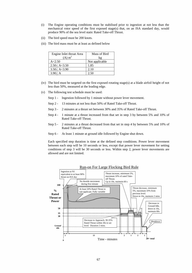
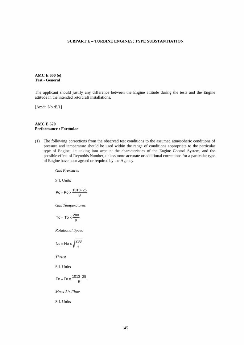
CS-E 600 Tests - General CS-E 620 Performance Correction CS-E 640 Pressure Loads CS-E 650 Vibration Surveys CS-E 660 Fuel Pressure and Temperature CS-E 670 Contaminated Fuel CS-E 680 Inclination and Gyroscopic Load Effects CS-E 690 Engine Bleed CS-E 700 Excess Operating Conditions CS-E 710 Rotor Locking Tests CS-E 720 Continuous Ignition CS-E 730 Engine Calibration Tests CS-E 740 Endurance Tests CS-E 745 Engine Acceleration CS-E 750 Starting Tests CS-E 770 Low Temperature Starting Tests CS-E 780 Tests in Ice-Forming Conditions CS-E 790 Ingestion of Rain and Hail CS-E 800 Bird Strike and Ingestion CS-E 810 Compressor and Turbine Blade Failure CS-E 820 Over-torque Test CS-E 830 Maximum Engine Over-speed CS-E 840 Rotor Integrity CS-E 850 Compressor, Fan and Turbine Shafts CS-E 860 Turbine Rotor Over-temperature CS-E 870 Exhaust Gas Over-temperature Test CS-E 880 Tests with Refrigerant Injection for Take-Off and/or 2½-Minute OEI Power CS-E 890 Thrust Reverser Tests
Annex to ED Decision 2007/015/R
Amendment 1
5
CS-E 900 Propeller Parking Brake CS-E 910 Relighting in Flight CS-E 920 Over-temperature Test
SUBPART F – TURBINE ENGINES - ENVIRONMENTAL AND OPERATIONAL DESIGN REQUIREMENTS
CS-E 1000 General CS-E 1010 Fuel Venting CS-E 1020 Engine Emissions CS-E 1030 Time Limited Dispatch CS-E 1040 ETOPS
APPENDICES
Appendix A Certification Standard Atmospheric Concentrations for Rain and Hail
CS-E BOOK 2 - ACCEPTABLE MEANS OF COMPLIANCE
SUBPART A – GENERAL
AMC E 10 (b) Thrust Reversers AMC E 20 Engine Configuration and Interfaces AMC E 20 (f) Power Assurance Data for Engines with One or More OEI Power Ratings AMC E 25 Instructions for Continued Airworthiness AMC E 30 Assumptions AMC E 40 Ratings AMC E 40 (b)(3) 30-Second OEI and 2-Minute OEI Ratings AMC E 40 (d) Operating Limitations AMC E 50 Engine Control System AMC E 50 (e) Rotor Integrity AMC E 50 (j) Controls - Engines Having A 30-Second OEI Power Rating AMC E 60 Provision for Instruments AMC E 60 (d) Provision for Instruments AMC E 70 Castings, Forgings, Welded Structures and Welded Components AMC E 80 Equipment AMC E 130 Fire Protection AMC E 135 Electrical Bonding AMC E 140 Test- Engine Configuration AMC E 150 (a) Tests - General Conduct of Tests AMC E 170 Engine Systems and Component Verification AMC E 180 Propeller Functioning Tests
SUBPART B – PISTON ENGINES; DESIGN AND CONSTRUCTION
AMC E 210 Failure Analysis
SUBPART C – PISTON ENGINES; TYPE SUBSTANTIATION
AMC E 300 (f) Conditions Applicable to all Tests - Torque Measurement AMC E 320 Performance Correction AMC E 340 Vibration Tests AMC E 350 Calibration Tests AMC E 380 Low Temperature Starting Tests AMC E 440 (b)(3) Endurance Test – Schedule for Engine Incorporating a Turbocharger AMC E 470 Contaminated Fuel
Annex to ED Decision 2007/015/R
Amendment 1

6
SUBPART D – TURBINE ENGINES; DESIGN AND CONSTRUCTION
AMC E 500 Functioning – Control of Engines (Turbine Engines for Aeroplanes) AMC E 510 Safety Analysis AMC E 515 Engine Critical Parts AMC E 520 (a) Strength – High Cycle Fatigue AMC E 520 (c)(1) Strength – Shedding of Blades AMC E 525 Continued Rotation AMC E 540 Strike and Ingestion of Foreign Matter AMC E 560 Fuel System AMC E 570 Oil System
SUBPART E – TURBINE ENGINES; TYPE SUBSTANTIATION
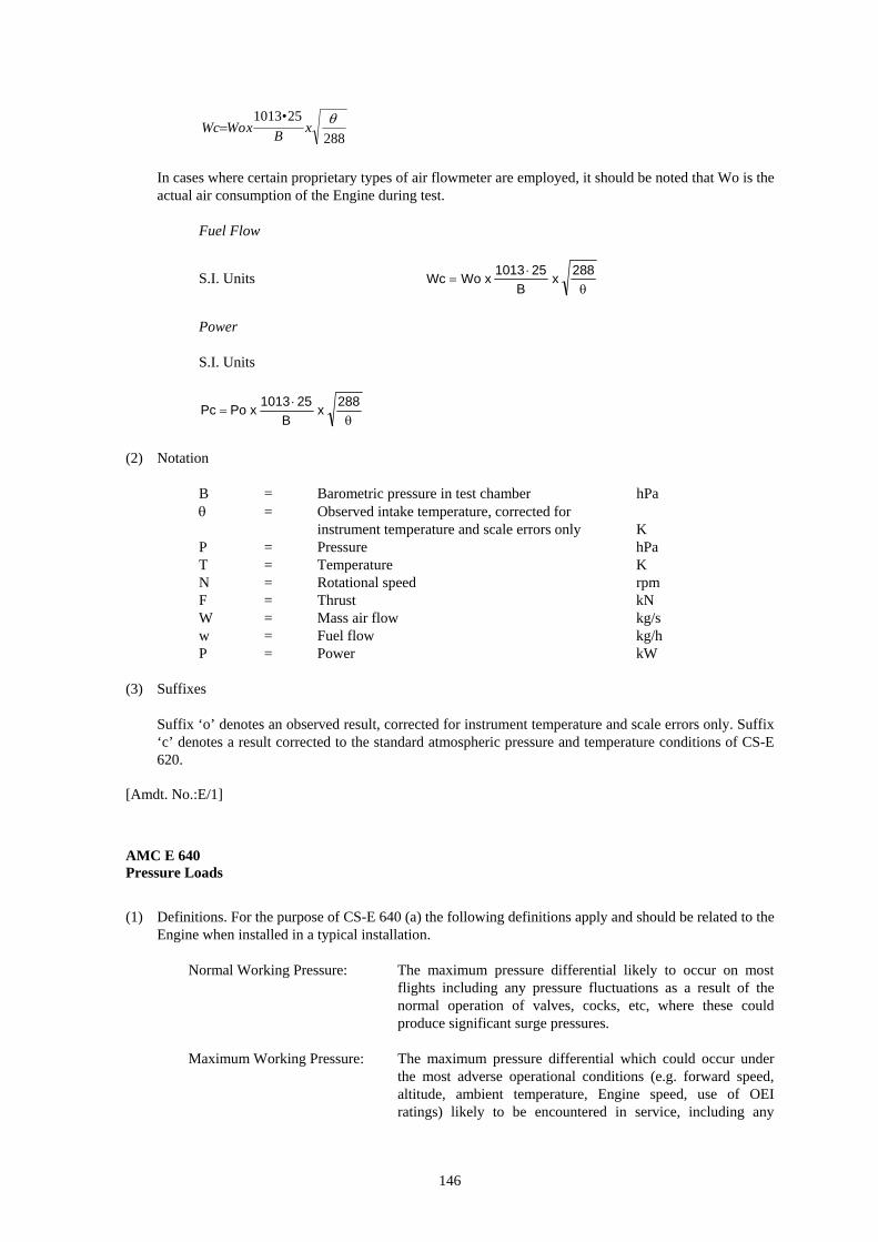
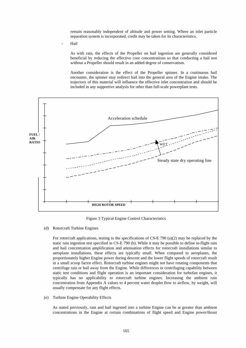
AMC E 600 (e) Test - General AMC E 620 Performance : Formulae AMC E 640 Static Pressure and Fatigue Tests AMC E 650 Vibration Surveys AMC E 660 Fuel Pump Tests (Turbine Engines for Aeroplanes) AMC E 670 Contaminated Fuel Testing AMC E 680 Inclination and Gyroscopic Load Effects AMC E 690 Engine Bleed AMC E 700 Excess Operating Conditions (Turbine Engines for Aeroplanes) AMC E 710 Rotor Locking Tests AMC E 720 (a) Continuous Ignition AMC E 730 Calibration Tests AMC E 740 (c)(3) Endurance Tests AMC E 740 (f)(1) Multi-Spool Engines AMC E 740 (g)(1) Endurance Tests – Incremental Periods AMC E 740 (h)(2) Endurance Tests - Inspection Checks AMC E 745 Engine Acceleration AMC E 750 (b) Starting Tests AMC E 770 Low Temperature Starting Tests AMC E 780 Tests in Ice-Forming Conditions (Engines for Aeroplanes) AMC E 790 Rain and Hail Ingestion AMC E 790 (a)(2) Rain and Hail Ingestion – Turbine Engine Power/Thrust Loss and Instability
in Extreme Conditions of Rain and Hail AMC E 800 Bird Strike and Ingestion AMC E 810 Compressor and Turbine Blade Failure AMC E 820 (a)(2) Over-torque Test AMC E 830 (c) Maximum Engine Over-speed AMC E 840 Rotor Integrity AMC E 850 Compressor, Fan and Turbine Shafts AMC E 870 (a)(3) Exhaust Gas Over-temperature Test AMC E 890 Thrust Reverser Tests AMC E 920 Over-temperature Test
SUBPART F – TURBINE ENGINES - ENVIRONMENTAL AND OPERATIONAL DESIGN SPECIFICATIONS
AMC E 1000 Environmental and Operational Design Specifications - General AMC E 1020 Engine Emissions AMC E 1030 Time Limited Dispatch
Annex to ED Decision 2007/015/R
Amendment 1

7
PREAMBLE
CS-E Amendment 1 Effective: 10/12/2007
The following is a list of paragraphs affected by this amendment. Contents (General lay-out) Amended (NPA 3/2005) Book 1 Subpart A • CS-E 10 Editorial change • CS-E 15 Amended (NPA 4/2005) • CS-E 20 Editorial change • CS-E 25 Editorial change • CS-E 30 Editorial change • CS-E 40 Editorial change • CS-E 50 Amended (NPA 4/2005) plus editorial change • CS-E 60 Editorial change • CS-E 70 Editorial change • CS-E 80 Editorial change • CS-E 130 Amended (NPA 3/2005) plus editorial change • CS-E 135 Created (NPA 3/2005) • CS-E 140 Editorial change • CS-E 150 Editorial change • CS-E 170 Editorial change • CS-E 180 Editorial change Subpart B • CS-E 210 Editorial change Subpart C • CS-E 300 Editorial change • CS-E 320 Editorial change • CS-E 340 Editorial change • CS-E 350 Editorial change • CS-E 360 Editorial change • CS-E 380 Editorial change • CS-E 440 Editorial change • CS-E 470 Editorial change Subpart D • CS-E 500 Editorial change • CS-E 510 Editorial change • CS-E 515 Editorial change • CS-E 520 Editorial change • CS-E 525 Editorial change • CS-E 540 Editorial change • CS-E 560 Editorial change • CS-E 570 Editorial change • CS-E 580 Amended (NPA 3/2005) Subpart E • CS-E 600 Editorial change • CS-E 620 Editorial change
Annex to ED Decision 2007/015/R
Amendment 1
8
• CS-E 640 Editorial change • CS-E 650 Editorial change • CS-E 660 Editorial change • CS-E 670 Editorial change • CS-E 680 Editorial change • CS-E 690 Editorial change • CS-E 700 Editorial change • CS-E 710 Editorial change • CS-E 720 Editorial change • CS-E 730 Editorial change • CS-E 740 Editorial change • CS-E 745 Editorial change • CS-E 750 Editorial change • CS-E 770 Editorial change • CS-E 780 Editorial change • CS-E 790 Editorial change • CS-E 800 Editorial change • CS-E 810 Editorial change • CS-E 820 Editorial change • CS-E 830 Editorial change • CS-E 840 Editorial change • CS-E 850 Editorial change • CS-E 870 Editorial change • CS-E 890 Editorial change • CS-E 920 Editorial change Subpart F • CS-E 1000 Editorial change • CS-E 1020 Editorial change • CS-E 1030 Amended (NPA 3/2005) Book 2 AMC - Subpart A • AMC E 10 (b) Created by renaming AMC E 10(b) • AMC E 10 (c) Deleted and moved to AMC E 10(b) • AMC E 20 Editorial change • AMC E 20 (f) Editorial change • AMC E 25 Editorial change • AMC E 30 Amended (NPA 3/2005) • AMC E 40 Editorial change • AMC E 40 (b)(3) Editorial change • AMC E 40 (d) Editorial change • AMC E 50 Amended (NPA 3/2005) • AMC E 50 (e) Editorial change • AMC E 50 (j) Editorial change • AMC E 60 Editorial change • AMC E 60 (d) Amended (NPA 3/2005) • AMC E 70 Editorial change • AMC E 80 Amended (NPA 3/2005) • AMC E 130 Amended (NPA 3/2005) • AMC E 135 Created (NPA 3/2005) • AMC E 140 Editorial change • AMC E 150 (a) Editorial change • AMC E 150 (f) Deleted and moved to AMC E 740(h)(2). • AMC E 170 Amended (NPA 3/2005)
Annex to ED Decision 2007/015/R
Amendment 1

9
• AMC E 180 Editorial change AMC - Subpart B • AMC E 210 Editorial change AMC - Subpart C • AMC E 300 (f) Editorial change • AMC E 320 Editorial change • AMC E 340 Editorial change • AMC E 350 Editorial change • AMC E 380 Editorial change • AMC E 440(b)(3) Editorial change • AMC E 470 Editorial change AMC - Subpart D • AMC E 500 Editorial change • AMC E 510 Amended (NPA 3/2005) • AMC E 515 Editorial change • AMC E 520 (a) Editorial change • AMC E 520 (c)(1) Editorial change • AMC E 525 Editorial change • AMC E 540 Editorial change • AMC E 560 Editorial change • AMC E 570 Editorial change AMC - Subpart E • AMC E 600 (e) Editorial change • AMC E 620 Editorial change • AMC E 640 Editorial change • AMC E 650 Editorial change • AMC E 660 Editorial change • AMC E 670 Editorial change • AMC E 680 Editorial change • AMC E 690 Editorial change • AMC E 700 Editorial change • AMC E 710 Editorial change • AMC E 720 (a) Editorial change • AMC E 730 Editorial change • AMC E 740 (c)(3) Amended (NPA 3/2005) • AMC E 740 (f)(1) Editorial change • AMC E 740 (g)(1) Editorial change • AMC E 740 (h)(2) Created by renaming AMC E 150(f) • AMC E 745 Editorial change • AMC E 750 (b) Editorial change • AMC E 770 Editorial change • AMC E 780 Editorial change • AMC E 790 Editorial change • AMC E 790 (a)(2) Editorial change • AMC E 800 Editorial change • AMC E 810 Editorial change • AMC E 820 (a)(2) Created (NPA 3/2005)
Annex to ED Decision 2007/015/R
Amendment 1

10
• AMC E 830 (c) Created (NPA 3/2005) • AMC E 840 Editorial change • AMC E 850 Editorial change • AMC E 870 (a)(3) Created (NPA 3/2005) • AMC E 890 Editorial change • AMC E 920 Editorial change AMC - Subpart E • AMC E 1000 Editorial change • AMC E 1020 Editorial change • AMC E 1030 Created (NPA 3/2005)
Annex to ED Decision 2007/015/R
Amendment 1
11
EASA Certification Specifications
for Engines
CS-E
Book 1
Airworthiness code
Annex to ED Decision 2007/015/R
Amendment 1

12
Annex to ED Decision 2007/015/R
Amendment 1

13
SUBPART A – GENERAL
CS-E 10 Applicability
(a) This CS-E contains airworthiness specifications for the issue of type certificates, and changes to those certificates, for Engines, in accordance with Part 21.
(b) CS-E contains the specifications for the approval for use of the Engine with a thrust reverser, if fitted. If compliance is shown, the specific thrust reverser approved for use will be noted in the Engine certification documentation. Otherwise, the documentation will be endorsed to indicate that the use of a thrust reverser is prohibited. (See AMC E 10 (b))
(c) The specifications of subparts A, B and C apply to Piston Engines. Any necessary variations of the specifications of subparts B and C for Piston Engines intended for use in rotorcraft will be decided in accordance with 21A.16.
(d) The specifications of subparts A, D, E and F apply to Turbine Engines.
[Amdt. No.:E/1]
CS-E 15 Terminology
(a) The terminology of this CS-E 15 must be used in conjunction with the issue of CS-Definitions current at the date of issue of this CS-E. Where used in CS-E, the terms defined in this paragraph and in CS-Definitions are identified by initial capital letters.
(b) All Engines
Extremely Remote: means unlikely to occur when considering the total operational life of a number of aircraft of the type in which the Engine is installed, but nevertheless, has to be regarded as being possible. Where numerical values are used this may normally be interpreted as a probability in the range 10–7 to 10–9 per Engine flight hour.
Reasonably Probable: means unlikely to occur often during the operation of each aircraft of the type but which may occur several times during the total operational life of each aircraft of the types in which the Engine may be installed. Where numerical values are used this may normally be interpreted as a probability in the range 10–3 to 10–5 per Engine flight hour.
Remote: means unlikely to occur to each aircraft during its total operational life but may occur several times when considering the total operational life of a number of aircraft of the type in which the Engine may be installed. When numerical values are used, this may normally be interpreted as a probability in the range 10–5 to 10–7 per Engine flight hour.
Annex to ED Decision 2007/015/R
Amendment 1

14
(c) Turbine Engines
Hazardous Engine Effect: means an effect identified as such under CS-E 510.
Major Engine Effect: means an effect identified as such under CS-E 510.
Minor Engine Effect: means an effect identified as such under CS-E 510.
(d) For piston Engines
Boost Pressure means the power setting measured relative to standard sea-level atmospheric pressure.
Charge Cooling means the percentage degree of charge cooling, quantitatively expressed as:
((t2 – t3) / (t2 – t1)) x 100
where:
t1 is the temperature of the air entering the charge cooler coolant radiator in the powerplant,
t2 is the temperature of the charge without cooling, and
t3 is the temperature of the charge with cooling.
Manifold Pressure means the absolute static pressure measured at the appropriate point in the induction system.
(e) Terms associated with Engine Critical Parts
Approved Life: means the mandatory replacement life of a part which is approved by the Agency.
Attributes: means inherent characteristics of a finished part that determine its capability.
Damage Tolerance: means an element of the life management process that recognises the potential existence of component imperfections as the result of inherent material structure, material processing, component design, manufacturing or usage and addresses this situation through the incorporation of fracture resistant design, fracture mechanics, process control, and non-destructive inspection.
Engine Critical Part: means a part that relies upon meeting prescribed integrity specifications of CS-E 515 to avoid its Primary Failure, which is likely to result in a Hazardous Engine Effect.
Engine Flight Cycle: means the flight profile, or combination of profiles, upon which the Approved Life is based.
Engineering Plan: means a compilation of the assumptions, technical data and actions required to establish and to maintain the life capability of an Engine Critical Part. The Engineering Plan is established and executed as part of the pre- and post-certification activities.
Annex to ED Decision 2007/015/R
Amendment 1

15
Manufacturing Plan: means a compilation of the part specific manufacturing process constraints, which must be included in the manufacturing definition (drawings, procedures, specifications, etc.) of the Engine Critical Part to ensure that it meets the design intent as defined by the Engineering Plan.
Primary Failure: means a Failure of a part which is not the result of the prior Failure of another part or system.
Service Management Plan: means a compilation of the processes for in-service maintenance and repair to ensure that an Engine Critical Part achieves the design intent as defined by the Engineering Plan.
[Amdt. No.:E/1]
CS-E 20 Engine Configuration and Interfaces (See AMC E 20)
(a) The list of all the parts and equipment, including references to the relevant drawings, which defines the proposed type design of the Engine, must be established.
(b) The aircraft airworthiness code which is assumed as being applicable to the intended installation of the Engine must be identified under CS-E 30.
(c) The aircraft parts and equipment that may be mounted on, or driven by, the Engine, which are not part of the declared Engine configuration and therefore are not covered by the Engine Type Certificate must be identified.
(d) Manuals must be provided containing instructions for installing and operating the Engine. These instructions must contain a definition of the physical and functional interfaces with the aircraft and aircraft equipment. They must also include a description of the Primary and all Alternate Modes, and any Back-up System, together with any associated limitations, of the Engine Control System and its interface with the aircraft systems, including the Propeller when applicable.
(e) Engine performance data, compatible with the Engine acceptance and operating limitations, must be provided for aircraft certification performance, handling and stressing purposes. The data must be such that the power/thrust of a ‘minimum’ and a ‘maximum’ Engine can be derived and must include means of determining the effects on performance of variations of Engine bleed and power off-take, forward speed, ambient pressure, temperature and humidity.
(f) For Engines having one or more OEI Ratings, data must be provided on Engine performance characteristics and variability to enable the aircraft manufacturer to establish power assurance procedures. (See AMC E 20 (f))
[Amdt. No.:E/1]
CS-E 25 Instructions for Continued Airworthiness (See AMC E 25)
(a) In accordance with 21A.61 (a), manual(s) must be established containing instructions for continued airworthiness of the Engine. They must be updated as necessary according to changes to existing instructions or changes in Engine definition.
Annex to ED Decision 2007/015/R
Amendment 1

16
(b) The instructions for continued airworthiness must contain a section titled airworthiness limitations that is segregated and clearly distinguishable from the rest of the document(s).
For Engine Critical Parts, this section must also include any mandatory action or limitation for in-service maintenance and repair identified in the Service Management Plan required under CS-E 515.
(1) For all Engines, the airworthiness limitations section must set forth each mandatory replacement time, inspection interval and related procedure required for type certification.
(2) For Engines having 30-Second OEI and 2-Minute OEI power ratings, in addition to complying with CS-E 25 (b)(1), the airworthiness limitations section must also prescribe the mandatory post-flight inspections and maintenance actions associated with any use of either the rated 30-Second OEI or 2-Minute OEI Power. The adequacy of these inspections and maintenance actions must be validated and an in-service Engine evaluation programme must be established to assure the adequacy of the data of CS-E 20 (f) pertaining to power availability and the instructions for the mandatory post flight inspections and maintenance actions.
The programme must include service Engine tests or equivalent service Engine test experience on Engines of similar design and/or evaluations of service usage of the 30-Second / 2-Minute OEI ratings.
(c) The following information must be considered, as appropriate, for inclusion into the manual(s) required by CS-E 25 (a).
(1) A detailed description of the Engine and its components, systems and installations.
(2) Handling instructions, including proper procedures for uncrating, de inhibiting, acceptance checking, lifting and attaching accessories, with any necessary checks.
(3) Basic control and operating information describing how the Engine components, systems and installations operate. Information describing the methods of starting, running, testing and stopping the Engine or its components and systems including any special procedures and limitations that apply.
(4) Servicing information that covers details regarding servicing points, capacities of tanks, reservoirs, types of fluids to be used, pressures applicable to the various systems, locations of lubrication points, lubricants to be used and equipment required for servicing.
(5) Scheduling information for each part of the Engine that provides the recommended periods at which it should be cleaned, inspected, adjusted, tested and lubricated, and the degree of inspection, the applicable serviceability limits, and work recommended at these periods. Necessary cross-references to the airworthiness limitations section must also be included. In addition, if appropriate, an inspection programme must be included that states the frequency of the inspections necessary to provide for the continued airworthiness of the Engine.
(6) Troubleshooting information describing probable malfunctions, how to recognise those malfunctions and the remedial action for those malfunctions.
(7) Information describing the order and method of removing the Engine and its parts and replacing parts, the order and method of disassembly and assembly, with any necessary precautions to be taken. Instructions for proper ground handling, crating and shipping must also be included.
(8) Cleaning and inspection instructions that cover the material and apparatus to be used and methods and precautions to be taken. Methods of inspection must also be included.
(9) Details of repair methods for worn or otherwise non-serviceable parts and components along with the information necessary to determine when replacement is necessary. Details of all relevant fits and clearances.
Annex to ED Decision 2007/015/R
Amendment 1

17
(10) Instructions for testing including test equipment and instrumentation.
(11) Instructions for storage preparation, including any storage limits.
(12) A list of the tools and equipment necessary for maintenance and directions as to their method of use.
[Amdt. No.:E/1]
CS-E 30 Assumptions (See AMC E 30)
(a) In the course of establishing compliance with CS-E certain assumptions have to be made concerning the conditions that may be imposed on the Engine when it is eventually installed in the aircraft. In order that the validity of the conditions assumed in the Engine certification may be assessed for any particular installation, prior to Engine certification, the details of the assumptions made must be submitted. These assumptions must be included in the Engine instructions for installation required under CS-E 20 (d).
(b) Where an Engine system relies on components which are not part of the Engine type design, the interface conditions and reliability specifications for those components upon which the Engine certification is based must be specified in the Engine instructions for installation directly or by reference to appropriate documentation.
[Amdt. No.:E/1]
CS-E 40 Ratings (See AMC E 40)
(a) Power ratings must be established for Take-off Power and/or Thrust and for Maximum Continuous Power and/or Thrust, for all Engines.
(b) Other ratings may also be established as:
(1) Piston Engines:
(i) Maximum Recommended Cruising Power.
(ii) Maximum Best Economy Cruising Power.
(2) Turbine Engines for Multi-Engine Aeroplanes
(i) 2 1/2-Minute OEI Power or Thrust
(ii) Continuous OEI Power or Thrust
(3) Turbine Engines for Multi-Engine Rotorcraft (See AMC E 40 (b)(3)):
(i) 30-Second OEI Power
(ii) 2-Minute OEI Power
(iii) 2 1/2-Minute OEI Power
(iv) 30-Minute OEI Power
(v) Continuous OEI Power
Annex to ED Decision 2007/015/R
Amendment 1

18
(c) The Engine thrust and/or power ratings will be based on standard atmospheric conditions, with no air bleed for aircraft services and with only those accessories installed which are essential for Engine functioning, including controls, unless otherwise declared in the Engine Type certificate data sheet.
(d) Operating limitations appropriate to the intended operating conditions for the Engine must be established. (See AMC E 40 (d))
(e) The Engine’s rated Powers/Thrusts and any operating limitations established under this CS-E 40 which must be respected by the crew of an aircraft must be listed in the Engine Type certificate data sheet specified in 21A.41. The Engine Type certificate data sheet must also identify, or make reference to, all other information found necessary for the safe operation of the Engine.
(f) The ratings established under this CS-E 40 must be defined for the lowest power/thrust that all Engines of the same type may be expected to produce under the conditions used to determine these ratings. The minimum testing must be defined, together with associated conditions, necessary for ensuring that the Engines will comply with this objective.
(g) In determining the Engine performance and operating limitations, the overall limits of accuracy of the Engine Control System and of the necessary instrumentation as defined in CS-E 60 (b) must be taken into account.
(h) For Piston Engines, each declared rating must be defined in terms of the power produced at a given power setting and Engine rotational speed.
[Amdt. No.:E/1]
CS-E 50 Engine Control System (See AMC E 50)
(a) Engine Control System Operation. It must be substantiated by tests, analysis or a combination thereof that the Engine Control System performs the intended functions in a manner which:
(1) Enables selected values of relevant control parameters to be maintained and the Engine kept within the approved operating limits over changing atmospheric conditions in the declared flight envelope.
(2) Complies with the operability specifications of CS-E 390, CS-E 500 (a) and CS-E 745, as appropriate, under all likely system inputs and allowable Engine power or thrust demands, unless it can be demonstrated that this is not required for non-dispatchable specific Control Modes in the intended application. In such cases, the Engine approval will be endorsed accordingly.
(3) Allows modulation of Engine power or thrust with adequate sensitivity and accuracy over the declared range of Engine operating conditions, and
(4) Does not create unacceptable thrust or power oscillations.
(b) Control Transitions. It must be demonstrated that, when a Fault or Failure results in a change from one Control Mode to another, or from one channel to another, or from the Primary System to the Back-up System, the change occurs so that:
(1) The Engine does not exceed any of its operating limitations,
(2) The Engine does not surge, stall, flame-out or experience unacceptable thrust or power changes or oscillations, or other unacceptable characteristics, and
Annex to ED Decision 2007/015/R
Amendment 1

19
(3) If the flight crew is required to initiate, respond to or be aware of the Control Mode change, there must be provision for a means to alert the crew. This provision must be described in the Engine instructions for installation and the crew action described in the Engine instructions for operation.
The magnitude of any change in thrust or power and the associated transition time must be identified and described in the Engine instructions for installation and operation.
(c) Engine Control System Failures. The Engine Control System must be designed and constructed so that:
(1) The rate for Loss of Thrust (or Power) Control (LOTC/LOPC) events, consistent with the safety objective associated with the intended aircraft application, can be achieved,
(2) In the Full-up Configuration, the system is essentially single Fault tolerant for electrical and electronic Failures with respect to LOTC/LOPC events.
(3) Single Failures of Engine Control System components do not result in a Hazardous Engine Effect,
(4) Foreseeable Failures or malfunctions leading to local events in the intended aircraft installation, such as fire, overheat, or Failures leading to damage to Engine Control System components, must not result in a Hazardous Engine Effect due to Engine Control System Failures or malfunctions.
(d) System Safety Assessment. When complying with CS-E 210 or CS-E 510, a system safety assessment must be completed for the Engine Control System. This assessment must identify Faults or Failures that result in a change in thrust or power, a transmission of erroneous data, or an effect on Engine operability together with the predicted frequency of occurrence of these Faults or Failures. (See also CS-E 110 (e))
(e) Protection Systems. (See AMC E 50 (e))
(1) When electronic over-speed protection systems are provided, the design must include a means for testing the system to establish the availability of the protection function. The means must be such that a complete test of the system can be achieved in the minimum number of cycles. If the test is not fully automatic, the specification for a manual test must be contained in the Engine instructions for operation.
(2) When over-speed protection is provided through hydromechanical or mechanical means, it must be demonstrated by test or other acceptable means that the over-speed function remains available between inspection and maintenance periods.
(f) Software and Programmable Logic Devices. All associated software and encoded logic must be designed, implemented and verified to minimise the existence of errors by using an approved method consistent with the criticality of the performed functions.
(g) Aircraft Supplied Data.
Single Failures leading to loss, interruption or corruption of Aircraft-Supplied Data, or data shared between Engines must:
(1) Not result in a Hazardous Engine Effect for any Engine.
(2) Be detected and accommodated. The accommodation strategy must not result in an unacceptable change in thrust or power or an unacceptable change in Engine operating and starting characteristics. The effects of these Failures on Engine power or thrust, Engine operability and starting characteristics throughout the flight envelope must be evaluated and documented.
The specification of CS-E 50 (g)(2) does not apply to thrust or power command signals from the aircraft.
(h) Aircraft Supplied Electrical Power.
Annex to ED Decision 2007/015/R
Amendment 1

20
(1) The Engine Control System must be designed so that the loss or interruption of electrical power supplied from the aircraft to the Engine Control System will not:
(i) Result in a Hazardous Engine Effect,
(ii) Cause the unacceptable transmission of erroneous data.
The effect of the loss or interruption of aircraft supplied electrical power must be taken into account in complying with CS-E 50 (c)(1).
(2) When an Engine dedicated power source is required for compliance with CS-E 50 (h)(1), its capacity should provide sufficient margin to account for Engine operation below idle where the Engine Control System is designed and expected to recover Engine operation automatically.
(3) The need for, and the characteristics of, any electrical power supplied from the aircraft to the Engine Control System for starting and operating the Engine, including transient and steady state voltage limits, must be identified and declared in the Engine instructions for installation.
(4) Low voltage transients outside of the power supply voltage limitations, declared under CS-E 50 (h)(3), must meet the specifications of CS-E 50 (h)(1). The Engine Control System must resume normal operation when aircraft supplied electrical power returns to within the declared limits.
(i) Air Pressure Signal.
The effects of blockage or leakage of the signal lines on the Engine Control System must be considered as part of the system safety assessment of CS-E 50 (d) and the appropriate design precautions adopted.
(j) Engines having a 30-Second OEI Power Rating must incorporate means or provision for means for automatic availability and automatic control of the 30-Second OEI Power within its operating limitations. (See AMC E 50 (j))
(k) Means for shutting down the Engine rapidly must be provided.
[Amdt. No.:E/1]
CS-E 60 Provision for Instruments (See AMC E 60)
(a) Provision must be made for the installation of instrumentation necessary to ensure operation in compliance with the Engine operating limitations. Where, in presenting the safety analysis, or complying with any other specification, dependence is placed on instrumentation which is not otherwise mandatory in the assumed aircraft installation, then this instrumentation must be specified in the Engine instructions for installation and declared mandatory in the Engine approval documentation.
(b) A list of the instruments necessary for control of the Engine must be provided in the Engine instructions for installation. The overall limits of accuracy and transient response required of such instruments for control of the operation of the Engine must also be stated so that the suitability of the instruments as installed may be assessed.
(c) The sensors together with associated wiring and signal conditioning must be segregated, physically and electrically, to the extent necessary to ensure that the probability of a Fault propagating from instrumentation and monitoring functions to control functions or vice versa is consistent with the Failure effect of the Fault.
(d) Rotorcraft turbine Engines having 30-Second and 2-Minute OEI Power Ratings must (See AMC E 60 (d)):
Annex to ED Decision 2007/015/R
Amendment 1

21
(1) Have means, or provision for means, to alert the pilot when the Engine is at the 30-Second OEI and the 2-Minute OEI Power levels, when the event begins, and when the time interval expires.
(2) Have means or provision for means, which cannot be reset in flight, to:
(i) Automatically record each usage and duration of power at the 30-Second and 2-Minute OEI Power levels.
(ii) Alert maintenance personnel in a positive manner, that the Engine has been operated at either or both of the 30-Second and 2-Minute OEI Power levels and permit retrieval of recorded data; and
(3) Have means, or provision for means, to enable routine verification of the proper operation of the above means.
(e) Instrumentation enabling the flight crew to monitor the functioning of the turbine cooling system must be provided unless evidence shows that:
(1) Other existing instrumentation provides adequate warning of Failure or impending Failure, or
(2) Failure of the cooling system would not lead to Hazardous Engine Effects before detection, or
(3) The probability of Failure of the cooling system is Extremely Remote.
Appropriate inspections must be promulgated in the relevant manuals.
[Amdt. No.:E/1]
CS-E 70 Materials and Manufacturing Methods (See AMC E 70)
(a) The suitability and durability of materials used in the Engine must be established on the basis of experience or tests. The assumed design values of properties of materials must be suitably related to the minimum properties stated in the material specification.
(b) Manufacturing methods and processes must be such as to produce sound structure and mechanisms which retain the original mechanical properties under reasonable service conditions.
[Amdt. No.:E/1]
CS-E 80 Equipment (See AMC E 80)
(a) Equipment Drives and Mountings
(1) Mountings and drives for all equipment installed on the Engine must be designed:
(i) To permit safe operation of the Engine with the equipment fitted, and
(ii) So that Failure of equipment will not result in further damage likely to produce a Hazardous Engine Effect.
(2) Mountings and drives for equipment identified under CS-E 20 (c) must be designed and located so as to minimise the possibility of defective equipment necessitating Engine shut-down as a result of:
(i) Contamination or major loss of the Engine oil supply, or
Annex to ED Decision 2007/015/R
Amendment 1

22
(ii) Engine malfunctioning through the application of excessive torque, loose parts falling into the Engine, flailing of the drives, etc.
(b) The equipment identified under CS-E 20 (a) must be approved as an integral part of the Engine and must meet the relevant specifications of CS-E. Unless the specifications prescribed in subpart C or E, as appropriate, will subject this equipment to such cycles of operation as to adequately represent all the critical conditions affecting its airworthiness to which it may be expected to be exposed during service, the equipment specification must state those additional airworthiness specifications for which evidence of compliance will be needed.
(c) The equipment identified under CS-E 20 (c) will be accepted for use on an Engine subject to:
(1) The equipment meeting the interface specifications identified under CS-E 20 (d);
(2) Evidence of satisfactory compliance with CS-E 80 (a);
(3) Being approved under the relevant aircraft Type Certificate.
(d) Equipment with high-energy rotors must be such as to meet one of the following:
(1) Failures will not result in significant non containment of high energy debris, or
(2) An acceptable level of integrity of the design, including the high energy parts, has been established, or
(3) An appropriate combination of (1) and (2).
[Amdt. No.:E/1]
CS-E 90 Prevention of Corrosion and Deterioration
(a) Each Engine component and each item of equipment must be protected from corrosion and deterioration in an approved manner.
(b) Materials which will render the Engine inherently self-protecting against corrosion, without the use of internal and external corrosion inhibitors, must be used wherever possible.
CS-E 100 Strength
(a) The maximum stresses developed in the Engine must not exceed values conforming to those established by satisfactory practice for the material involved, due account being taken of the particular form of construction and the most severe operating conditions. Where a new type of material is involved, evidence must be available to substantiate the assumed material characteristics. For Turbine Engines, due consideration must be given to the effects of any residual stresses in Engine Critical Parts.
(b) The Engine components which form part of the Engine mounting and any other parts of the Engine liable to be critically affected must, when the Engine is properly supported by a suitable Engine-mounting structure, have sufficient strength to withstand the flight and ground loads for the aircraft as a whole in combination with the local loads arising from the operation of the Engine.
(c) Each Engine must be designed and constructed to function throughout its declared flight envelope and operating range of rotational speeds and power/thrust, without inducing excessive stress in any Engine part because of vibration and without imparting excessive vibration forces to the aircraft structure.
Annex to ED Decision 2007/015/R
Amendment 1
23
CS-E 110 Drawings and Marking of Parts – Assembly of Parts
(a) The drawings for each Engine component and each item of equipment must give full particulars of the design and must indicate the materials used in terms of their specifications. The protective finish and, where applicable, the surface finish, must be indicated. Any tests necessary to establish the manufacturing quality of components or equipment must be quoted on the relevant drawings either directly or by reference to other suitable documents.
(b) Except where otherwise agreed each part must be marked so that it can be identified with the drawing to which it was made. The position of the markings must be indicated on the drawing.
(c) Certain parts (including Engine Critical Parts, see CS-E 515) as may be required by the Agency must be marked and the constructor must maintain records related to this marking such that it is possible to establish the relevant manufacturing history of the parts.
(d) Turbine Engine parts, the incorrect assembly of which could result in Hazardous Engine Effects, must be designed so as to minimise the risk of incorrect assembly or, where this is not practical, permanently marked so as to indicate their correct position when assembled.
(e) As part of the system safety assessment of CS-E 50 (d), the possibility and subsequent effect of incorrect fitment of instruments, sensors or connectors must be assessed. Where necessary, design precautions must be taken to prevent incorrect configuration of the system.
CS-E 120 Identification
(a) The Engine identification must comply with 21A.801 (a) and (b), and 21A.805.
(b) Major Engine modules that can be changed independently in service must be suitably identified so as to ensure traceability of parts and to enable proper control over the interchangeability of such modules with different Engine variants.
CS-E 130 Fire Protection (See AMC E 130)
(a) The design and construction of the Engine and the materials used must minimise the probability of the occurrence and spread of fire during normal operation and Failure conditions and must minimise the effects of such a fire. In addition, the design and construction of Engines must minimise the probability of the occurrence of an internal fire that could result in structural Failure or Hazardous Engine Effects.
(b) Except as required by CS-E 130 (c), each external line, fitting and other component which contains or conveys flammable fluid during normal Engine operation must be at least Fire Resistant. Components must be shielded or located to safeguard against the ignition of leaking flammable fluid.
(c) Tanks which contain flammable fluid and any associated shut-off means and supports, which are part of and attached to the Engine, must be Fireproof either by construction or by protection, unless damage by fire will not cause leakage or spillage of a hazardous quantity of flammable fluid. For a Piston Engine having an integral oil sump of less than 23.7 litres capacity, the oil sump need not be Fireproof nor be enclosed by a Fireproof shield but still must comply with CS-E 130 (b).
(d) An Engine component designed, constructed and installed to act as a firewall must be:
(1) Fireproof; and,
Annex to ED Decision 2007/015/R
Amendment 1

24
(2) Constructed so that no hazardous quantity of air, fluid or flame can pass around or through the firewall; and,
(3) Protected against corrosion.
(e) In addition to specifications of CS-E 130 (a) and (b), Engine control system components which are located in a designated fire zone must be at least Fire Resistant
(f) Unintentional accumulation of hazardous quantities of flammable fluid within the Engine must be prevented by draining and venting.
(g) Those features of the Engine which form part of the mounting structure or Engine attachment points must be Fireproof, either by construction or by protection, unless not required for the particular aircraft installation and so declared in accordance with CS-E 30.
[Amdt. No.:E/1]
CS-E 135 Electrical Bonding (See AMC E 135)
Any components, modules, equipment and accessories that are susceptible to or are potential sources of static discharges or currents from electrical Faults, must be designed and constructed so as to be grounded to the main Engine earth, as necessary to minimise the accumulation of electro-static or electrical charge that would cause:
- Injury from electrical shock,
- Unintentional ignition in areas where flammable fluids or vapours could be present,
- Unacceptable interference with electrical or electronic equipment.
[Amdt. No.:E/1]
CS-E 140 Tests - Engine Configuration (See AMC E 140)
(a) The configuration of the Engine or components or parts to be tested must be sufficiently representative of the type design for the purpose of the test.
(b) All automatic controls and protections must be in operation unless it is accepted that this is not possible or that they are not required because of the nature of the test.
(c) Variable devices that are not intended to be adjusted during Engine operation must be set in accordance with the type design prior to each test, except when the particular test demands adjustments to be made or as required by paragraphs relating to specific tests. Other variable devices must operate or be operated in a manner consistent with both the type design and the operating instructions to be provided under CS-E 20 (d) unless otherwise necessary for the purpose of the test.
(d) (1) All equipment drives not essential to the satisfactory functioning of the Engine must be disconnected or off loaded during the Calibration Tests of CS-E 350 or CS-E 730. Throughout all other tests, except as required by CS-E 140 (d)(2), they must be suitably loaded, either with the equipment listed in the constructor's declaration or with slave units of a suitable type.
Annex to ED Decision 2007/015/R
Amendment 1

25
(2) When running the additional endurance test sequence required by CS-E 740 (c)(3)(iii), the accessory drives and mounting attachments need not be loaded if it can be substantiated that there is no significant effect to the durability of any accessory drive or Engine component. However, the equivalent Engine output power extraction from the power turbine rotor assembly must be added to the Engine shaft output.
(e) Certain features prescribed in CS-E 500 and CS-E 560 to CS-E 590 may be incorporated as part of the aircraft installation rather than as part of the Engine type design. In this case, where the performance of the Engine is affected, the features concerned must be satisfactorily represented throughout the Engine tests.
(f) In addition to the combined Engine and Propeller tests required by CS-E 180, other tests prescribed in Certification Specifications for Propellers may be conducted jointly with Engine tests where it is accepted that these combined tests do not constitute a less severe test for either the Engine or the Propeller or both.
[Amdt. No.:E/1]
CS-E 150 Tests - General Conduct of Tests
(a) The fuel and oil used for all tests must normally be chosen from those specified by the Applicant, but, where it may have relevance to the results of any particular test, the actual fuel and oil to be used (including any additives) must be justified. (See AMC E 150 (a))
(b) During all tests, only servicing and minor repairs must be permitted except that major repairs or replacement of parts may be resorted to, provided that the parts in question are subjected to an agreed level of penalty testing.
(c) Except where declared by the Applicant, no artificial means of increasing the humidity of the ambient air must be employed.
(d) For all tests, parameters relevant to the purpose of the test must be agreed and recorded at appropriate times during the test. Where possible, Engine conditions must be allowed to stabilise before observations are taken. In particular, observations taken less than 3 minutes after a change of Engine conditions must not be included in assessment of performance, unless the rating cannot be used for more than 3 minutes.
(e) Adjustments made in compliance with CS-E 140 (c) must be checked and unintended variations from the original settings recorded after each test.
(f) All test bed equipment and all measuring equipment used for tests must be appropriately calibrated.
[Amdt. No.:E/1]
CS-E 160 Tests – History
(a) In order to enable compliance with 21A.21 (c)(3) of Part 21, should a Failure of an Engine part occur during the certification tests, its cause must be determined and the effect on the airworthiness of the Engine must be assessed. Any necessary corrective actions must be determined and substantiated.
(b) The development history of the Engine or component or equipment of the Engine must be considered. Any significant event, relevant to airworthiness of the Engine, occurring during development and not corrected before certification tests, must also be assessed under CS-E 160 (a).
Annex to ED Decision 2007/015/R
Amendment 1

26
CS-E 170 Engine Systems and Component Verification (See AMC E 170)
For those systems or components which cannot be adequately substantiated by other tests of CS-E, additional tests or analyses must be conducted to demonstrate that the systems or components are able to perform the intended functions in all declared environmental and operating conditions.
[Amdt. No.:E/1]
CS-E 180 Propeller Functioning Tests (See AMC E 180)
(a) If approval of the Engine for use with a Variable Pitch Propeller is sought by the Applicant, a sufficient portion of the tests prescribed in CS-P, must be made either during or on the completion of the endurance test of CS-E 440 or CS- 740 to demonstrate that the Propeller-Engine combination will function satisfactorily. The minimum number of tests which will be acceptable for Engine approval is given below.
(b) The following tests must be carried out:
(1) Pitch change cycles
(i) Turbine Engines
(A) Fifty forward pitch change cycles, by operation of Propeller control. (Only applicable when a separate Propeller control is provided). Each cycle must include the maximum range of pitch likely to be experienced in normal use.
(B) 100 operations with-drawing the flight fine pitch lock. These may be combined with the Engine decelerations prescribed in CS-E 740 for the endurance test.
(ii) Piston Engines – For Engines to be approved for use with a variable pitch Propeller, 100 representative forward pitch change cycles must be made across the range of pitch and rotational speed.
(2) 10 feathering cycles. In addition, for turbine Engines, where the oil tank is to be approved as part of the Engine, the ability to complete one cycle (i.e. one feather and unfeather) when the supply of oil has been reduced to the feathering reserve oil (see CS-E 570 (f)(3)(i)) must be demonstrated.
(3) 200 reverse pitch change cycles (braking or manoeuvring, whichever is greater), and sustaining the appropriate maximum declared Engine conditions for 1 minute during each cycle. In this case, the periods of the endurance test covering the range of cruising conditions may be reduced by a total of 3 hours.
(4) 1 reverse (manoeuvring) pitch change cycle, sustaining the appropriate maximum declared Engine conditions for 5 minutes.
(c) Additional tests with Reversible Pitch Propellers on Piston Engines:
(1) Where approval of an Engine for use with Reversible Pitch Propellers is sought, the appropriate tests of Certification Specifications for Propellers must be run on Engines sufficiently representative of the type design.
(2) After completion of these tests, those parts of the Engines which may be affected by the reversed thrust or air flow, must be removed and examined and must be shown to have suffered no adverse effects.
Annex to ED Decision 2007/015/R
Amendment 1

27
(d) Any other tests considered necessary to demonstrate that the Propeller-Engine combination will function satisfactorily.
[Amdt. No.:E/1]
CS-E 190 Engines for Aerobatic Use
Where approval is sought for an Engine intended for use in an aeroplane for which the Flight Manual will approve aerobatics or semi-aerobatic flight, the ability of the Engine to continue to function safely in conditions of inverted flight or for intentional negative g conditions for specified periods must be demonstrated. Where the evidence is considered to be acceptable, and such tests as are necessary have been completed satisfactorily, the Engine Type certificate data sheet will be endorsed by means of a note, e.g. ‘the Engine may be used under sustained negative g or inverted flight conditions for continuous periods not exceeding... seconds’.
Annex to ED Decision 2007/015/R
Amendment 1

28
Annex to ED Decision 2007/015/R
Amendment 1

29
SUBPART B — PISTON ENGINES, DESIGN AND CONSTRUCTION
CS-E 210 Failure Analysis (See AMC E 210)
(a) A Failure analysis of the Engine, including the control system for a typical installation must be made to establish that no single Fault, or double Fault if one of the Faults may be present and undetected during pre-flight checks, could lead to unsafe Engine conditions beyond the normal control of the flight crew.
(b) In certain cases the Failure analysis will depend on assumed installed conditions. Such assumptions must be stated in the analysis.
[Amdt. No.:E/1]
CS-E 230 De-Icing and Anti-Icing Precautions
(a) The design of the Engine induction system must be such as to minimise the risk of ice formation adversely affecting the functioning of the Engine and, if necessary, must include provision for the use of a means for ice prevention
(b) Where necessary, provision must be made for the fitting of an induction thermometer or ice indicator, as appropriate for the control of the particular system.
CS-E 240 Ignition
All spark-ignition Engines shall comply with the following:
(a) The Engine shall be equipped either with:
(1) A dual ignition system having entirely independent magnetic and electrical circuits, including spark plugs, or,
(2) An ignition system which will function with at least equivalent reliability.
(b) If the design of the ignition system includes redundancy :
(1) The maximum power reduction resulting from loss of redundancy shall be declared in the appropriate manual(s).
(2) Provision shall be made to establish the serviceability of the ignition system. The associated procedures and required inspection intervals shall be specified in the appropriate manual(s).
Annex to ED Decision 2007/015/R
Amendment 1

30
CS-E 250 Fuel System
(a) Each fuel specification to be approved, including any additive, and the associated limitations in flow, temperature and pressure that ensure proper Engine functioning under all intended operating conditions must be declared and substantiated.
(b) Any characteristic of fuel conforming to the specification(s) to be approved which is likely to adversely affect Engine functioning or durability, must be identified so that, where necessary, Engine or rig testing using appropriate fuel may be conducted.
(c) Filters, strainers or other equivalent means must be provided to protect the fuel system from malfunction due to contaminants. These devices must have the capacity to accommodate any likely quantity of contaminants, including water, in relation to recommended servicing intervals. These means may be provided in the aircraft fuel system; in such case, the characteristics of the means shall be specified in the instructions for installation.
(d) It shall not be possible for fuel to drain into the Engine when it is not running, in such quantities as to introduce a risk of ‘hydraulicing’ or in any way adversely affect the mechanical reliability of the Engine.
(e) Design precautions must be taken against the possibility of errors and inadvertent or unauthorised changes in setting of all fuel control adjusting means.
CS-E 260 Engine Cooling System
(a) The design and construction of the Engine cooling system must ensure adequate cooling in all normal operating conditions within the flight envelope. Any reliance upon assumed installed conditions shall be declared in the instructions for installation.
(b) For liquid-cooled Engines, it must be shown that the coolant will not boil under any normal operating condition within the flight envelope, under all additive concentrations approved for use.
(c) For liquid-cooled Engines, to prevent Engine malfunction due to overheating, appropriate means or provision for means shall be provided to detect loss of coolant.
CS-E 270 Lubrication System
(a) It shall not be possible for oil to drain into the Engine when it is not running, in such quantities as to introduce a risk of ‘hydraulicing’ or in any way adversely to affect the mechanical reliability of the Engine.
(b) The oil flow between the Engine lubrication system and the Propeller control system or other system utilising oil supplied by the Engine, shall not prevent oil pressure being maintained within approved limits at all operating conditions within the flight envelope, allowance being made for deterioration of the Engine.
(c) All parts of the oil system that are not inherently capable of accepting contaminants likely to be present in the oil or otherwise introduced into the oil system shall be protected by suitable filter(s) or strainer(s). These shall provide a degree of filtration sufficient to preclude damage to the Engine and Engine equipment and have adequate capacity to accommodate contaminants in relation to the specified servicing intervals. These filters or strainers may be provided as part of the aircraft; in such cases, their characteristics will be specified in the instructions for installation
Annex to ED Decision 2007/015/R
Amendment 1

31
(d) Adequate oil cooling shall be provided, or the required oil cooling means shall be defined in the instructions for installation, to ensure that temperature limits are not exceeded in any normal operating condition within the flight envelope.
(e) Each type of oil, and brand if appropriate, must be declared and substantiated, along with any associated limitations.
(f) Any oil characteristic which is likely to be critical for Engine functioning or durability must be identified. Where necessary, Engine or rig testing using appropriate oil shall be conducted.
CS-E 290 Hand Turning
It must be possible to rotate the crankshaft in controlled slow motion. Where this is effected by hand-turning gear as distinct from the Propeller, a means of safe guarding the operator against injury, if the Engine starts or kicks back, must be provided. It must not be possible to damage the Engine by use of the hand-turning gear.
Annex to ED Decision 2007/015/R
Amendment 1

32
Annex to ED Decision 2007/015/R
Amendment 1

33
SUBPART C — PISTON ENGINES, TYPE SUBSTANTIATION
CS-E 300 Conditions Applicable to All Tests
(a) Coolant Flow. (Applicable to liquid-cooled Engines only). Equipment must be provided to permit simultaneous observation of the coolant flow to each bank of cylinders.
(b) Cylinder Temperatures. (Applicable to air-cooled Engines only). Cylinder temperature observations must be made on all cylinders throughout the Rating Checks, Detonation, Endurance and Calibration Tests. The location of the point(s) at which the temperature of each cylinder is measured must be recorded.
(c) Temperatures – General. Except as prescribed in CS-E 300 (d) and (e), the temperatures must be held throughout each stage, within the limits given in Table 1, to the values declared as the maxima appropriate to the power, where that power is a limiting condition.
TABLE 1
Temperature Applicable to Limits (°C) Oil inlet All Engines ± 3 Coolant outlet Liquid-cooled Engines ± 3 Cylinder Air-cooled Engines ± 5 Charge Cooler All Engines ± 3 (when fitted)
(d) Temperatures – At High Powers
(1) For the stages in which the Engine is run at Maximum Continuous Power, the limits of CS-E 300 (c) apply to 50% of the total running period of each stage; the remaining 50% of the period must be run at not less than the Maximum Best Economy Cruising temperatures.
(2) For the stages in which the Engine is run at Take-off Power for not less than 1 hour continuously, the limits of CS-E 300 (c) apply to a continuous period of not less than 15 minutes in each hour only, during which at least one full set of observations must be taken; the remainder of each hour must be run at not less than the Maximum Best Economy Cruising temperatures.
(3) The limits of CS-E 300 (c) are not applicable to stages in which the Engine is run for less than 15 minutes continuously at any one power.
(e) Temperature - Calibrations Tests. For the power performance items of the calibration tests in CS-E 350, the limits of CS-E 300 (c) must apply except that the declared temperature may be obtained and set at the commencement of each curve and thereafter be left unadjusted, provided that the temperatures do not vary appreciably from those declared.
(f) Torque Measurement - For testing requiring the measurement of Engine power, an acceptable method of establishing the torque of the Engine shall be defined. (See AMC E 300 (f))
[Amdt. No.:E/1]
Annex to ED Decision 2007/015/R
Amendment 1

34
CS-E 320 Performance Correction (See AMC E 320)
(a) All performance results shall be corrected to the conditions of the Standard Atmosphere, in accordance with an internationally recognised method.
(b) Where Engine power is affected by cylinder temperature or coolant temperature the performance results shall be corrected to the minimum Engine power within the range of temperatures to be approved for use.
[Amdt. No.:E/1]
CS-E 330 Tests - General
A single Engine must be used for all the tests except that, if so desired, the vibration, calibration, and detonation tests may be made on Engines of the same type as the Engine used for the other tests so long as there is essential similarity to that Engine. The vibration tests may be made during preliminary development of the type provided that the design standard and power rating of the Engine used do not differ essentially from the prototype.
CS-E 340 Vibration Tests (See AMC E 340)
(a) Tests by approved methods must be made on an appropriate mounting to satisfy the Agency that no dangerous torsional or flexural vibration characteristic exists in the dynamic system throughout the operating range of crankshaft rotational speed and Engine power used in flight. In the absence of adequate evidence to the contrary, a maximum stress shown to be safe for continuous use must be regarded as the maximum safe stress. The range must include low power operation and must comprise crankshaft speeds from idling to the highest of the following: 110% of the desired Maximum Continuous speed, 105% of the desired maximum Take-off speed, or the maximum desired Over-speed. Observations must be made at increments of 50 crankshaft rpm throughout this range. Tests covering the range up to the desired maximum take-off speed rating must also be made with that cylinder not firing which is most critical from the point of view of vibration.
(b) A representative flight Propeller must be used for these tests. In the case of a Fixed Pitch Propeller a ‘throttle’ curve must be run. In the case of a Variable Pitch Propeller the procedure must normally be the same, with the Propeller blade pitch set to a fixed value which will give maximum Engine power at maximum Engine rotational speed. If the results of the tests with a Variable Pitch Propeller show the existence of a serious critical vibration within the operating speed range, a more detailed investigation must be made at speeds within the critical range.
(c) A harmonic analysis of the vibration records must be made by a method approved by the Agency, at each increment of Engine speed and the results plotted against Engine speed so that the predominant orders of vibration and their relative magnitudes are clearly shown throughout the operating speed range of the Engine.
(d) In cases where torsional strain in the Propeller shaft has been measured by means of a torsional strain type of vibration pickup, the torque amplitude of the orders of vibration must be plotted about the mean torque curve for the Engine. In other cases where for practical reasons it is impossible to use the strain type of torsional vibration pickups, and a seismic type of instrument attached to the free end of the crankshaft is used, the angular displacement amplitudes of the various orders of vibration at the free end of the crankshaft must be plotted against Engine speed.
Annex to ED Decision 2007/015/R
Amendment 1
35
(e) A tabulation based on the theoretical and test results obtained must be made detailing the following information relating to resonant conditions for the most serious criticals: Engine speed, order of vibration, frequency, maximum and minimum values of vibration stress in the crankshaft and Propeller shaft and the region at which they occur. Diagrams showing the displacement curves for the modes of vibration associated with these criticals should also be presented.
(f) If excessive vibration is found to be present in the operating range of the Engine, suitable remedial measures must be taken prior to the endurance test of CS-E 440.
(g) If moderate vibration is found to exist, which is not sufficiently serious to warrant the introduction of modifications but needs proof of its effect on the Engine, a vibration penalty test must be substituted for those stages of the endurance test as are considered most suitable and must include sufficient duration under the most adverse vibration condition to establish the ability of the Engine to resist fatigue Failure.
[Amdt. No.:E/1]
CS-E 350 Calibration Tests (See AMC E 350)
(a) The power characteristics of the Engine must be established, under all normal operating conditions within the declared flight envelope, by means of sufficient calibration testing.
(b) In order to identify the Engine power changes that may occur during the endurance test of CS-E 440, sea level power calibration curves of the test Engine shall be established at the beginning and the end of the endurance test
[Amdt. No.:E/1]
CS-E 360 Detonation Tests
For spark ignition Engines:
(a) A test shall be conducted to demonstrate that the Engine can function without detonation at all operating conditions within the flight envelope. If the design of the ignition system includes redundancy, this test shall be repeated in degraded operating modes.
(b) During the test of CS-E 360 (a), the Engine shall be operated throughout the range from the lowest Engine rotational speed intended to be used for cruising, to the declared maximum Engine rotational speed, at the conditions of power setting, mixture setting (if applicable), oil temperature, coolant or cylinder-head temperatures, and manifold air pressure and air temperature, most likely to cause detonation. An agreed method shall be used to determine the degree of detonation.
[Amdt. No.:E/1]
CS-E 370 Starting Tests
(a) At least 100 successful Engine starts must be made, either during or at the end of the endurance test of CS-E 440, using the normal means of starting and the technique recommended by the Engine constructor. Half the starts must be made with the Engine cold and half with the Engine hot.
Annex to ED Decision 2007/015/R
Amendment 1

36
(b) Time to start, number of attempts, ambient air temperature, and (in the case of electric starters) current consumption, must be recorded at the beginning of each 10-hour period. In addition, a record must be made of the means and amount of priming, if employed, and whether or not oil dilution is used.
(c) If alternative means of starting are provided for emergency or standby use, not less than 10 additional starts on each of the alternative means of starting provided must be made. These tests may be made either as part of the endurance test of CS-E 440 or separately in which case they must be followed by a suitable strip examination.
CS-E 380 Low Temperature Starting Tests (See AMC E 380)
(a) Tests shall be carried out to demonstrate that the Engine can be started under the lowest temperature conditions to be approved, without causing damage to the Engine. At least 25 Engine starts shall be made at oil inlet temperatures, evenly distributed between + 5°C and the minimum temperature to be declared for starting. Before each start attempt, the oil inlet temperature and the temperature of the Engine shall be substantially the same as the temperature of the ambient air.
(b) The tests shall be carried out using representative aircraft and ground starting equipment and using the starting technique defined in the operating instructions.
(c) The Engine shall be fitted with a representative flight Propeller or its equivalent, and representative aircraft equipment, as defined in CS-E 20 (c).
(d) Both before and after the completion of the low temperature starting tests, the Engine and equipment shall be submitted to a strip examination to demonstrate that the condition of the Engine is satisfactory for continued safe operation. Measurements shall be made of those dimensions liable to change by reason of wear or distortion.
[Amdt. No.:E/1]
CS-E 390 Acceleration Tests
(a) The tests of CS-E 390 (a)(1) and (2) must be carried out at the end of the endurance test of CS-E 440 without heated intake air and repeated, when applicable, with intake air heated to the maximum temperature likely to be experienced at any operating condition within the flight envelope.
(1) For all Engines, except two-speed supercharged Engines, five accelerations must be made from idling conditions to Take-off Power.
(2) For two-speed supercharged Engines, five accelerations must be made from idling conditions up to each condition:
(i) To Take-off Power with supercharger in low gear
(ii) To Maximum Continuous Power with supercharger in high gear.
(b) The Engine shall respond without hesitation and accelerate smoothly throughout the range, when the power lever is moved from the minimum flight idle position to the Take-off or Maximum Continuous position, as appropriate, in not more than one second.
(c) If the Engine is to be approved for use with a propeller with variable or adjustable pitch, for the tests of CS-E 390(a) the propeller pitch shall be set such that the Engine will produce not less than rated Take-off power at the Engine rotational speed used to define the Take-off rating (see CS-E 40 (h) ).
Annex to ED Decision 2007/015/R
Amendment 1

37
(d) Each acceleration (except for those with a supercharger in high gear) shall be made starting from the minimum temperatures for acceleration from idle to be declared in the operating limitations. Each acceleration with a supercharger in high gear shall be made from ambient conditions.
CS-E 400 Over-speed Tests
(a) The tests of (1) and (2) shall be completed during or at the end of the endurance test of CS-E 440.
(1) All Engines, except two-speed supercharged Engines. 20 runs, each of 30 seconds duration, at the declared Maximum Engine Over-speed or at a speed 5% in excess of the declared maximum Engine rotational speed, whichever is greater. The power setting for these runs shall not be less than that declared for the Maximum Continuous rating.
(2) Two-speed Supercharged Engines. 20 runs, each of 30 seconds duration, at the declared Maximum Engine Over-speed or at a speed 5% in excess of the declared maximum Engine rotational speed, whichever is the greater, 10 with the supercharger in low gear and 10 with the supercharger in high gear. The power setting for these runs shall not be less than that declared for the Maximum Continuous rating.
(b) A further test consisting of a total of 10-minutes run in stages of not less than one minute shall be made at the declared Maximum Over-speed or at a speed not less than 5% in excess of the declared maximum Engine rotational speed, whichever is greater. The power for this test shall be not greater than 30% Take-off Power. The oil inlet temperature shall be within 30°C of the declared maximum temperature for take-off. This test may be run on a dynamometer.
CS-E 430 Water Spray Tests
(a) Installation Conditions. With the Engine suitably cowled or shielded to be fully representative of an installed Engine, a water spray must be applied throughout three periods of running.
(b) Running Conditions. Each period of running must comprise:
- Start
- Warm up
- Ignition checks
- 5 minutes at Take-off Power
- 15 minutes at Maximum Continuous Power
- 15 minutes at Maximum Best Economy Cruising Power
- 25 minutes at 60% of Maximum Continuous Power at 75% of Maximum Best Economy Cruising crankshaft rotational speed
- Ignition check and accelerations.
Two-speed supercharged Engines must run the whole test in low gear.
(c) Interval Conditions. An interval of 24 hours must be allowed after each period of running. No adjustment or artificial drying-off must be undertaken from the commencement of the test and, when not running, the Engine must be completely covered in a manner which will fully promote moisture
Annex to ED Decision 2007/015/R
Amendment 1

38
penetration. At the conclusion of the third cycle of running and standing, the Engine must be subjected to 5 minutes running at Take-off Power without the water spray.
(d) Water Spray Conditions. The spray must be arranged to deliver water in a manner representative of very heavy rain over the whole frontal area of the Engine including cowling, air intakes, etc., but not necessarily the Propeller tips, throughout the full running time. The rate of delivery, R, must be assessed from the formula:
R = 12.2F litres/min
where F, in m2, is frontal area of nacelle.
CS-E 440 Endurance Test
(a) (1) The test must be made in the order defined in the appropriate schedule and in suitable non-stop parts. In the event of a stop occurring during any part, the part must be repeated unless it is agreed to be unnecessary. The complete test may need to be repeated if an excessive number of stops occur.
(2) The whole of the endurance test must be run with the oil pressure set to give the declared normal operating pressure at Maximum Continuous conditions except that one hour at Take-off conditions and nine hours at Maximum Continuous must be run with the pressure set to give the declared minimum for completion of the flight at Maximum Continuous conditions. The test conditions may be revised, if necessary, to avoid having to stop the Engine during particular parts in order to reset the oil pressure.
(3) Where the operating conditions are prescribed in terms of a percentage of Maximum Continuous Power, the crankshaft rotational speed, power setting and mixture setting (if applicable)mixture setting (if applicable) must be appropriate to the simulation of the most severe cruising conditions at this power. Where in such cases the power setting is not greater than that for Maximum Best Economy Cruising Power Conditions, the mixture setting (if applicable) mixture setting (if applicable) must be compatible with the power setting.
(4) Throughout each part of the endurance test, the crankshaft rotational speed and power setting must be maintained at, or as near as possible to, the declared maximum values appropriate to the Engine operating conditions prescribed. A repeat of the run might be required if, for any reason, the observed crankshaft rotational speed and power setting deviate by more than + 1.5% from the declared maximum values.
(5) Propellers. A representative flight Propeller must be used during this test.
(i) Variable Pitch Propellers. The blade setting of the Propeller need not be set precisely as for flight conditions. If, however, the blade setting does not allow the conditions, detailed in the test schedule agreed for the particular Engine, to be achieved, the limitations approved for the Engine will be based on the conditions at which the test is run.
(ii) Fixed Pitch Propellers. A sufficient number of Propellers, agreed prior to the commencement of the tests, must be used for reasonable approximations to the various power ratings to be made. The number normally acceptable is two, for instance, one primarily suited to Maximum Best Economy Cruising Power Conditions, and the other primarily suited to Maximum Continuous or Take-off conditions.
(iii) Limitations not Simultaneously Attainable. If a fixed pitch Propeller is fitted for the tests, the Engine must be operated at the maximum power setting or maximum crankshaft rotational speed appropriate to the conditions of the tests, whichever limitation is reached first.
(6) The Engine must be subjected to an agreed extent of pre-assembly inspection, and a record must be made of the dimensions liable to change by reason of wear, distortion and creep. A record must
Annex to ED Decision 2007/015/R
Amendment 1
39
also be made of the calibrations and settings of separately functioning Engine components and equipment (e.g. the control system, pumps, actuators, valves).
(b) Schedules
(1) Schedule for Unsupercharged Engines and Engines Incorporating Gear-driven, Single-speed Superchargers.
Part 1 A 30-hour run consisting of alternate 5 minute periods at Take-off Power and speed and Maximum Best Economy Cruising Power or Maximum Recommended Cruising Power conditions.
Part 2 A 20-hour run consisting of alternate periods of 1½ hours at Maximum Continuous Power and speed and ½ hour at 75% Maximum Continuous Power and 91% Maximum Continuous speed.
Part 3 A 20-hour run consisting of alternate periods of 1½ hours at Maximum Continuous Power and speed and ½ hour at 70% Maximum Continuous Power and 89% Maximum Continuous speed.
Part 4 A 20-hour run consisting of alternate periods of 1½ hours at Maximum Continuous Power and speed and ½ hour at 65% Maximum Continuous Power and 87% Maximum Continuous speed.
Part 5 A 20-hour run consisting of alternate periods of 1½ hours at Maximum Continuous Power and speed and ½ hour at 60% Maximum Continuous Power and 84.5% Maximum Continuous speed.
Part 6 A 20-hour run consisting of alternate periods of 1½ hours at Maximum Continuous Power and speed and ½ hour at 50% Maximum Continuous Power and 79.5% Maximum Continuous speed.
Part 7 A 20-hour run consisting of alternate 2½ hour periods at Maximum Continuous Power and speed and Maximum Best Economy Cruising Power or Maximum Recommended Cruising Power conditions.
(2) Schedule for Engine Incorporating a Gear-driven Two-speed Supercharger.
Part 1 A 30-hour run in the lower gear ratio consisting of alternate 5 minute periods at Take-off Power and speed and Maximum Best Economy Cruising Power or Maximum Recommended Cruising Power Conditions.
If a Take-off Power rating is desired in the higher gear ratio, 15 hours of the 30-hour run must be made in the higher gear ratio in alternate periods of 5 minutes at the power obtainable with the Take-off Critical Altitude power setting and Take-off speed and 5 minutes at 70% high ratio Maximum Continuous Power and 89% high ratio Maximum Continuous speed.
Part 2 A 15-hour run in the lower gear ratio consisting of alternate periods of one hour at Maximum Continuous Power and speed and ½ hour at 75% Maximum Continuous Power and 91% Maximum Continuous speed.
Part 3 A 15-hour run in the lower gear ratio consisting of alternate periods of one hour at Maximum Continuous Power and speed and ½ hour at 70% Maximum Continuous Power and 89% Maximum Continuous speed.
Part 4 A 30-hour run in the higher gear ratio at Maximum Continuous Power and speed.
Annex to ED Decision 2007/015/R
Amendment 1