certification specifications for normal, utility ... amdt 3.pdfcertification specifications for...
TRANSCRIPT

European Aviation Safety Agency
Certification Specifications
for Normal, Utility, Aerobatic, and
Commuter Category Aeroplanes
CS-23
Amendment 3 20 July 2012
Annex to ED Decision 2012/012/R
Amendment 3
Annex to ED Decision 2012/012/R
Amendment 3

CS-23
C-1
CONTENTS (general layout)
CS–23
NORMAL, UTILITY, AEROBATIC, AND COMMUTER CATEGORY
AEROPLANES PREAMBLE
BOOK 1 – AIRWORTHINESS CODE
SUBPART A – GENERAL SUBPART B – FLIGHT SUBPART C – STRUCTURE SUBPART D – DESIGN AND CONSTRUCTION SUBPART E – POWERPLANT SUBPART F – EQUIPMENT SUBPART G – OPERATING LIMITATIONS AND INFORMATION APPENDICES APPENDIX A – SIMPLIFIED DESIGN LOAD CRITERIA FOR CONVENTIONAL,
SINGLE-ENGINE AIRPLANES OF 2722 KG (6 000 POUNDS) OR LESS MAXIMUM WEIGHT
APPENDIX C – BASIC LANDING CONDITIONS APPENDIX D – WHEEL SPIN-UP LOADS APPENDIX F – TEST PROCEDURE FOR SELF-EXTINGUISHING MATERIALS IN
ACCORDANCE WITH CS 23.853, 23.855 AND 23.1359 APPENDIX G – INSTRUCTIONS FOR CONTINUED AIRWORTHINESS APPENDIX H – INSTALLATION OF AN AUTOMATIC POWER RESERVE (APR)
SYSTEM APPENDIX I – SEAPLANE LOADS APPENDIX J – ANTHROPOMORPHIC TEST DUMMIES FOR SHOWING
COMPLIANCE WITH 23.562
BOOK 2 – ACCEPTABLE MEANS OF COMPLIANCE (AMC) AMC – SUBPART C AMC – SUBPART D AMC – SUBPART E AMC – SUBPART F AMC – SUBPART G AMC – APPENDIX A BOOK 2 – FLIGHT TEST GUIDE (FTG) FTG – CONTENTS CHAPTER 1 – GENERAL
Annex to ED Decision 2012/012/R
Amendment 3
Annex to ED Decision 2012/012/R
Amendment 3

CS-23
C-2
CHAPTER 2 – FLIGHT CHAPTER 3 – DESIGN AND CONSTRUCTION CHAPTER 4 – POWERPLANT CHAPTER 5 – EQUIPMENT CHAPTER 6 – OPERATING LIMITATIONS AND INFORMATION APPENDIX 1 – POWER AVAILABLE APPENDIX 2 – CLIMB DATA REDUCTION APPENDIX 3 – STATIC MINIMUM CONTROL SPEED EXTRAPOLATION TO SEA
LEVEL APPENDIX 4 – CS–23 MANUALS, MARKINGS & PLACARDS CHECKLIST APPENDIX 5 – (RESERVED) APPENDIX 6 – SAMPLE KINDS OF OPERATING EQUIPMENT LIST APPENDIX 7 – USEFUL INFORMATION APPENDIX 8 – CONVERSION FACTORS TABLE APPENDIX 9 – AIRSPEED CALIBRATIONS APPENDIX 10 – GUIDE FOR DETERMINING CLIMB PERFORMANCE AFTER STC
MODIFICATIONS
Annex to ED Decision 2012/012/R
Amendment 3
Annex to ED Decision 2012/012/R
Amendment 3

CS-23
P-1
PREAMBLE
CS-23 Amendment 3 Effective: 20 July 2012
The following is a list of paragraphs affected by this amendment.
Book 1
Subpart D CS 23.851 Amended (NPA 2011-14)
Subpart E CS 23.1197 Amended (NPA 2011-14)
Book 2
AMC - Subpart D AMC 23.851(c) Amended (NPA 2011-14)
AMC - Subpart E AMC 23.1197 Created (NPA 2011-14)
CS-23 Amendment 2 (Corrigendum)
Effective: 28 September 2010
Subpart C Amended (rectification of administrative oversight)
CS-23 Amendment 2
Effective: 9 September 2010
The following is a list of paragraphs affected by this amendment.
Book 1
Subpart B
CS 23.221 Amended (Editorial correction)
Subpart D
CS 23.603 Amended (NPA 2009-06)
CS 23.813(b)(4) Amended (Editorial correction)
Subpart E
Annex to ED Decision 2012/012/R
Amendment 3
Annex to ED Decision 2012/012/R
Amendment 3

CS-23
P-2
CS 23.909 Amended (Editorial correction)
Appendices Appendix D Amended (Editorial correction)
Book 2
Subpart C AMC 23.573(a)(1)&(3) Amended (NPA 2009-06)
Subpart D
AMC 23.603 Deleted (NPA 2009-06)
AMC 23.613 Amended (NPA 2009-06)
AMC 23.629 Amended (NPA 2009-06 & Editorial correction)
Flight Test Guide (FTG)
192 Paragraph 23.909 Amended (Editorial correction)
207 Paragraph 23.959 Amended (Editorial correction)
208 Paragraph 23.961 Amended (Editorial correction)
307 Paragraph 23.1329 Amended (Editorial correction)
CS-23 Amendment 1 Effective: 12 February 2009
The following is a list of paragraphs affected by this amendment.
Book 1
Subpart B CS 23.49(c) Amended (NPA 2008-08)
CS 23.49(d) Created (NPA 2008-08)
Subpart C
CS 23.562(d) Created (NPA 2008-08)
CS 23.562(e) Amended (NPA 2008-08)
Annex to ED Decision 2012/012/R
Amendment 3
Annex to ED Decision 2012/012/R
Amendment 3

CS23 BOOK 1
101
EASA Certification Specifications for
Normal, Utility, Aerobatic, and Commuter Category Aeroplanes
CS23 Book 1
Airworthiness code
Annex to ED Decision 2012/012/R
Amendment 3
Annex to ED Decision 2012/012/R
Amendment 3

CS23 BOOK 1
1–A–1
SUBPART A — GENERAL
CS 23.1 Applicability
(a) This airworthiness code is applicable to –
(1) Aeroplanes in the normal, utility and aerobatic categories that have a seating configuration, excluding the pilot seat(s), of nine or fewer and a maximum certificated take off weight of 5670 kg (12 500 lb) or less; and
(2) Propellerdriven twinengined aeroplanes in the commuter category that have a seating configuration, excluding the pilot seat(s), of nineteen or fewer and a maximum certificated takeoff weight of 8618 kg (19 000 lb) or less.
CS 23.3 Aeroplane categories
(a) The normal category is limited to non aerobatic operations. Nonaerobatic operations include –
(1) Any manoeuvre incident to normal flying;
(2) Stalls (except whip stalls); and
(3) Lazy eights, chandelles and steep turns or similar manoeuvres, in which the angle of bank is not more than 60°.
(b) The utility category is limited to any of the operations covered under subparagraph (a); plus –
(1) Spins (if approved for the particular type of aeroplane); and
(2) Lazy eights, chandelles, and steep turns, or similar manoeuvres in which the angle of bank is more than 60° but not more than 90°.
(c) The aerobatic category is without restrictions, other than those shown to be necessary as a result of required flight tests.
(d) Commuter category operation is limited to any manoeuvre incident to normal flying, stalls (except whip stalls) and steep turns in which the angle of bank is not more than 60°.
(e) Except for commuter category, aeroplanes may be certificated in more than one category if the requirements of each requested category are met.
Annex to ED Decision 2012/012/R
Amendment 3
Annex to ED Decision 2012/012/R
Amendment 3

CS-23 BOOK 1
1–B–1
GENERAL
CS 23.21 Proof of compliance
(a) Each requirement of this subpart must be met at each appropriate combination of weight and centre of gravity within the range of loading conditions for which certification is requested. This must be shown –
(1) By tests upon an aeroplane of the type for which certification is requested, or by calculations based on, and equal in accuracy to, the results of testing; and
(2) By systematic investigation of each probable combination of weight and centre of gravity, if compliance cannot be reasonably inferred from combinations investigated.
(b) The following general tolerances are allowed during flight testing. However, greater tolerances may be allowed in particular tests –
Item Tolerance
Weight +5%, –10%
Critical items affected by weight +5%, –1%
C.G. ±7% total travel
CS 23.23 Load distribution limits
(a) Ranges of weight and centres of gravity within which the aeroplane may be safely operated must be established and must include the range for lateral centres of gravity if possible loading conditions can result in significant variation of their positions.
(b) The load distribution must not exceed –
(1) The selected limits;
(2) The limits at which the structure is proven; or
(3) The limits at which compliance with each applicable flight requirement of this subpart is shown.
CS 23.25 Weight limits
(a) Maximum weight. The maximum weight is the highest weight at which compliance with each applicable requirement of CS-23 (other than those complied with at the design landing weight) is shown. The maximum weight must be established so that it is –
(1) Not more than the least of –
(i) The highest weight selected by the applicant; or
(ii) The design maximum weight, which is the highest weight at which compliance with each applicable structural loading condition of CS-23 (other than those complied with at the design landing weight) is shown; or
(iii) The highest weight at which compliance with each applicable flight requirement is shown, and,
(2) Not less than the weight with:-
(i) Each seat occupied, assuming a weight of 77kg (170 lbs) for each occupant for normal and commuter category aeroplanes, and 86kg (190 lbs) for utility and acrobatic category aeroplanes, except that seats other than pilot seats may be placarded for a lesser weight; and
(A) Oil at full capacity, and
(B) At least enough fuel for maximum continuous power operation of at least 30 minutes for day-VFR approved aeroplanes and at least 45 minutes for night-VFR and IFR approved aeroplanes; or
(ii) The required minimum crew, and fuel and oil to full tank capacity.
(b) Minimum weight. The minimum weight (the lowest weight at which compliance with each applicable requirement of CS-23 is shown) must be established so that it is not more than the sum of –
(1) The empty weight determined under CS 23.29;
(2) The weight of the required minimum crew (assuming a weight of 77 kg (170 lb) for each crew member); and
(3) The weight of –
(i) For turbojet powered aeroplanes, 5% of the total fuel capacity of that particular fuel tank arrangement under investigation; and
(ii) For other aeroplanes, the fuel necessary for one-half hour of operation at maximum continuous power.
SUBPART B – FLIGHT
Annex to ED Decision 2012/012/R
Amendment 3
Annex to ED Decision 2012/012/R
Amendment 3

CS-23 BOOK 1
1–B–2
CS 23.29 Empty weight and correspond-ing centre of gravity
(a) The empty weight and corresponding centre of gravity must be determined by weighing the aeroplane with –
(1) Fixed ballast;
(2) Unusable fuel determined under CS 23.959; and
(3) Full operating fluids, including –
(i) Oil;
(ii) Hydraulic fluid; and
(iii) Other fluids required for normal operation of aeroplane systems, except potable water, lavatory precharge water, and water intended for injection in the engines.
(b) The condition of the aeroplane at the time of determining empty weight must be one that is well defined and can be easily repeated.
CS 23.31 Removable ballast
Removable ballast may be used in showing compliance with the flight requirements of this subpart, if –
(a) The place for carrying ballast is properly designed and installed, and is marked under CS 23.1557; and
(b) Instructions are included in the aeroplane flight manual, approved manual material, or markings and placards, for the proper placement of the removable ballast under each loading condition for which removable ballast is necessary.
CS 23.33 Propeller speed and pitch l imits
(a) General. The propeller speed and pitch must be limited to values that will assure safe operation under normal operating conditions.
(b) Propellers not controllable in flight. For each propeller whose pitch cannot be controlled in flight –
(1) During take-off and initial climb at the all-engine(s)-operating climb speed specified in CS 23.65, the propeller must limit the engine rpm, at full throttle or at maximum allowable take-off manifold pressure, to a speed not greater than the maximum allowable take-off rpm; and
(2) During a closed throttle glide at VNE, the propeller may not cause an engine speed above 110% of maximum continuous speed.
(c) Controllable pitch propellers without constant speed controls. Each propeller that can be controlled in flight, but that does not have constant speed controls, must have a means to limit the pitch range so that –
(1) The lowest possible pitch allows compliance with sub-paragraph (b)(1); and
(2) The highest possible pitch allows compliance with sub-paragraph (b)(2).
(d) Controllable pitch propellers with constant speed controls. Each controllable pitch propeller with constant speed controls must have –
(1) With the governor in operation, a means at the governor to limit the maximum engine speed to the maximum allowable take-off rpm; and
(2) With the governor inoperative, the propeller blades at the lowest possible pitch, with take-off power, the aeroplane stationary, and no wind, either:-
(i) A means to limit the maximum engine speed to 103 percent of the maximum allowable take-off r.p.m., or
(ii) For an engine with an approved overspeed, means to limit the maximum engine and propeller speed to not more than the maximum approved overspeed.
PERFORMANCE
CS 23.45 General
(a) Unless otherwise prescribed, the performance requirements of this subpart must be met for –
(1) Still air and standard atmosphere;
(2) Ambient atmospheric conditions, for commuter category aeroplanes, for reciprocating engine-powered aeroplanes of more than 2 722 kg (6 000 lb) maximum weight and for turbine engine-powered aeroplanes.
(b) Performance data must be determined over not less than the following ranges of conditions –
(1) Aerodrome altitude from sea-level to 3048 m (10 000 ft); and
Annex to ED Decision 2012/012/R
Amendment 3
Annex to ED Decision 2012/012/R
Amendment 3

CS-23 BOOK 1
1–B–3
(2) For reciprocating engine-powered aeroplanes of 2 722 kg (6 000 lb) or less maximum weight, temperatures from standard to 30°C above standard; or
(3) For reciprocating engine-powered aeroplanes of more than 2 722 kg (6 000 lb) maximum weight and turbine engine-powered aeroplanes, temperature from standard to 30°C above standard, or the maximum ambient atmospheric temperature at which compliance with the cooling provisions of CS 23.1041 to 23.1047 is shown, if lower.
(c) Performance data must be determined with the cowl flaps or other means for controlling the engine cooling air supply in the position used in the cooling tests required by CS 23.1041 to 23.1047.
(d) The available propulsive thrust must correspond to engine power, not exceeding the approved power, less –
(1) Installation losses; and
(2) The power absorbed by the accessories and services appropriate to the particular ambient atmospheric conditions and the particular flight condition.
(e) The performance as affected by engine power must be based on a relative humidity of –
(1) 80% at and below standard temperature; and
(2) 34% at and above standard temperature plus 28°C (plus 50°F).
Between the two temperatures listed in sub-paragraphs (e) (1) and (e) (2) the relative humidity must vary linearly.
(f) Unless otherwise prescribed in determining the take-off and landing distances, changes in the aeroplane’s configuration, speed and power must be made in accordance with procedures established by the applicant for operation in service. These procedures must be able to be executed consistently by pilots of average skill in atmospheric conditions reasonably expected to be encountered in service.
(g) The following, as applicable, must be determined on a smooth, dry, hard-surfaced runway –
(1) Take-off distance of CS 23.53 (b);
(2) Accelerate-stop distance of CS 23.55;
(3) Take-off distance and take-off run of CS 23.59; and
(4) Landing distance of CS 23.75.
The effect on these distances of operation on other types of surface (e.g. grass, gravel) when dry, may be determined or derived and these surfaces listed in accordance with CS 23.1583 (p).
(h) For commuter category aeroplanes, the following also apply:
(1) Unless otherwise prescribed, the take-off, en-route, approach and landing configurations for the aeroplane must be selected;
(2) The aeroplane configuration may vary with weight, altitude and temperature, to the extent that they are compatible with the operating procedures required by sub-paragraph (h) (3);
(3) Unless otherwise prescribed, in determining the critical-engine-inoperative take-off performance, take-off flight path and accelerate-stop distance, changes in the aeroplane’s configuration, speed and power must be made in accordance with procedures established by the applicant for operation in service.
(4) Procedures for the execution of discontinued approaches and balked landings associated with the conditions prescribed in CS 23.67 (c) (4) and 23.77 (c) must be established; and
(5) The procedures established under sub-paragraphs (h) (3) and (h) (4) must –
(i) Be able to be consistently executed by a crew of average skill in atmospheric conditions reasonably expected to be encountered in service;
(ii) Use methods or devices that are safe and reliable; and
(iii) Include allowances for any reasonably expected time delays in the execution of the procedures.
CS 23.49 Stalling speed
(a) VSO and VS1 are the stalling speeds or the minimum steady flight speed (CAS) at which the aeroplane is controllable with –
(1) For reciprocating engine-powered aeroplanes, engine(s) idling, the throttle(s) closed or at not more than the power necessary for zero thrust at a speed not more than 110% of the stalling speed; and
Annex to ED Decision 2012/012/R
Amendment 3
Annex to ED Decision 2012/012/R
Amendment 3

CS-23 BOOK 1
1–B–4
(2) For turbine engine-powered aeroplanes, the propulsive thrust may not be greater than zero at the stalling speed, or, if the resultant thrust has no appreciable effect on the stalling speed, with engine(s) idling and throttle(s) closed;
(3) Propeller(s) in the take-off position;
(4) The aeroplane in the condition existing in the test in which VSO and VS1 are being used;
(5) Centre of gravity in the position which results in the highest value of VSO and VS1; and
(6) Weight used when VSO or VS1 are being used as a factor to determine compliance with a required performance standard.
(b) VSO and VS1 must be determined by flight tests using the procedure and meeting the flight characteristics specified in CS 23.201.
(c) Except as provided in sub-paragraph (d) of this paragraph, VSO at maximum weight must not exceed 113 km/h (61 knots) for –
(1) Single-engined aeroplanes; and
(2) Twin-engined aeroplanes of 2 722 kg (6 000 lb) or less maximum weight that cannot meet the minimum rate of climb specified in CS 23.67 (a) (1) with the critical engine inoperative.
(d) All single-engined aeroplanes, and those twin-engined aeroplanes of 2722 kg (6 000 lb) or less maximum weight, with a VSO of more than 113 km/h (61 knots) at maximum weight that do not meet the requirements of CS 23.67(a)(1), must comply with CS 23.562(d).
[Amdt 23/1]
CS 23.51 Take-off speeds
(a) For normal utility and aerobatic category aeroplanes, the rotation speed VR, is the speed at which the pilot makes a control input with the intention of lifting the aeroplane out of contact with the runway or water surface.
(1) For twin-engined landplanes, VR must not be less than the greater of 1·05 VMC or 1·10 VS1;
(2) For single engined landplanes, VR, must not be less than VS1; and
(3) For seaplanes and amphibians taking off from water, VR, must be a speed that is shown to be safe under all reasonably
expected conditions, including turbulence and complete failure of the critical engine.
(b) For normal utility and aerobatic category aeroplanes, the speed at 15 m (50 ft) above the take-off surface level must not be less than –
(1) For twin-engined aeroplanes, the highest of –
(i) A speed that is shown to be safe for continued flight (or land-back, if applicable) under all reasonably expected conditions, including turbulence and complete failure of the critical engine; or
(ii) 1·10 VMC; or
(iii) 1·20 VS1
(2) For single-engined aeroplanes, the higher of –
(i) A speed that is shown to be safe under all reasonably expected conditions, including turbulence and complete engine failure; or
(ii) 1·20 VS1.
(c) For commuter category aeroplanes the following apply:
(1) V1 must be established in relation to VEF as follows:
(i) VEF is the calibrated airspeed at which the critical engine is assumed to fail. The VEF must be selected for the aeroplane, but must not be less than 1·05 VMC determined under CS 23.149 (b) or, at the option of the applicant, not less than VMCG determined under CS 23.149(f).
(ii) The take-off decision speed, V1, is the calibrated airspeed on the ground at which, as a result of engine failure or other reasons, the pilot is assumed to have made a decision to continue or discontinue the take-off. The take-off decision speed, V1, must be selected for the aeroplane but must not be less than VEF plus the speed gained with the critical engine inoperative during the time interval between the instant at which the critical engine is failed and the instant at which the pilot recognises and reacts to the engine failure, as indicated by the pilot’s application of the first retarding means during the accelerate-stop determi-nation of CS 23.55.
(2) The rotation speed, VR, in terms of calibrated airspeed, must be selected for the
Annex to ED Decision 2012/012/R
Amendment 3
Annex to ED Decision 2012/012/R
Amendment 3

CS-23 BOOK 1
1–B–5
aeroplane and must not be less than the greatest of the following:
(i) V1; or
(ii) 1·05 VMC determined under CS 23.149 (b); or
(iii) 1·10 VSI; or
(iv) The speed that allows attaining the initial climb-out speed, V2, before reaching a height of 11 m (35 ft) above the take-off surface in accordance with CS 23.57 (c) (2).
(3) For any given set of conditions, such as weight, altitude, temperature and configuration, a single value of VR must be used to show compliance with both the one-engine-inoperative take-off and all-engine-operating take-off requirements.
(4) The take-off safety speed, V2, in terms of calibrated airspeed, must be selected for the aeroplane so as to allow the gradient of climb required in CS 23.67 (c) (1) and (c) (2) but must not be less than 1·10 VMC or less than 1·20 VSI.
(5) The one-engine-inoperative take-off distance, using a normal rotation rate at a speed 9.3 km/h (5 knots) less than VR established in accordance with sub-paragraph (c)(2), must be shown not to exceed the corresponding one-engine-inoperative take-off distance determined in accordance with CS 23.57 and 23.59 (a) (1) using the established VR. The take-off, otherwise performed in accordance with CS 23.57 must safely be continued from the point at which the aeroplane is 11 m (35 ft) above the take-off surface, at a speed not less than the established V2 minus 9.3 km/h (5 knots).
(6) With all engines operating, marked increases in the scheduled take-off distances determined in accordance with CS 23.59 (a) (2) may not result from over-rotation of the aeroplane or out-of-trim conditions.
CS 23.53 Take-off performance
(a) For normal, utility and aerobatic category aeroplanes the take-off distance must be determined in accordance with sub-paragraph (b), using speeds determined in accordance with CS 23.51 (a) and (b).
(b) For normal, utility and aerobatic category aeroplanes the distance required to take-off and climb to a height of 15 m (50 ft) above the take-off surface must be determined for each weight,
altitude and temperature within the operational limits established for take-off with –
(1) Take-off power on each engine;
(2) Wing flaps in the take-off position(s); and
(3) Landing gear extended.
(c) For commuter category aeroplanes, take-off performance as required by CS 23.55 to CS 23.59 must be determined with the operating engines within approved operating limitations.
CS 23.55 Accelerate-stop distance
For each commuter category aeroplane, the accelerate-stop distance must be determined as follows:
(a) The accelerate-stop distance is the sum of the distances necessary to –
(1) Accelerate the aeroplane from a standing start to VEF with all engines operating;
(2) Accelerate the aeroplane from VEF to V1, assuming the critical engine fails at VEF; and
(3) Come to a full stop from the point at which V1 is reached.
(b) Means other than wheel-brakes may be used to determine the accelerate-stop distances if that means –
(1) Is safe and reliable; and
(2) Is used so that consistent results can be expected under normal operating conditions.
CS 23.57 Take-off path
For each commuter category aeroplane, the take-off path is as follows;
(a) The take-off path extends from a standing start to a point in the take-off at which the aeroplane is 457 m (1 500 ft) above the take-off surface, at or below which height the transition from the take-off to the en-route configuration must be completed; and
(1) The take-off path must be based on the procedures prescribed in CS 23.45;
(2) The aeroplane must be accelerated on the ground to VEF at which point the critical engine must be made inoperative and remain inoperative for the rest of the take-off; and
(3) After reaching VEF, the aeroplane must be accelerated to V2.
Annex to ED Decision 2012/012/R
Amendment 3
Annex to ED Decision 2012/012/R
Amendment 3

CS-23 BOOK 1
1–B–6
(b) During the acceleration to speed V2, the nose gear may be raised off the ground at a speed not less than VR. However, landing gear retraction must not be initiated until the aeroplane is airborne.
(c) During the take-off path determination, in accordance with sub-paragraphs (a) and (b) –
(1) The slope of the airborne part of the take-off path must not be negative at any point;
(2) The aeroplane must reach V2 before it is 11m (35 ft) above the take-off surface and must continue at a speed as close as practical to, but not less than, V2, until it is 122 m (400 ft) above the take-off surface;
(3) At each point along the take-off path, starting at the point at which the aeroplane reaches 122 m (400 ft) above the take-off surface, the available gradient of climb must not be less than 1·2%; and
(4) Except for gear retraction and automatic propeller feathering, the aeroplane configuration must not be changed, and no change in power that requires action by the pilot may be made, until the aeroplane is 122 m (400 ft) above the take-off surface.
(d) The take-off path to 11 m (35 ft) above the take-off surface must be determined by a continuous take-off.
(e) The take-off flight path from 11 m (35 ft) above the take-off surface must be determined by synthesis from segments; and
(1) The segments must be clearly defined and must be related to distinct changes in configuration, power or speed;
(2) The weight of the aeroplane, the configuration and the power must be assumed constant throughout each segment and must correspond to the most critical condition prevailing in the segment; and
(3) The take-off flight path must be based on the aeroplane’s performance without ground effect.
CS 23.59 Take-off distance and take-off run
For each commuter category aeroplane, the take-off distance must be determined. The determination of the take-off run is optional.
(a) The take-off distance is the greater of –
(1) The horizontal distance along the take-off path from the start of the take-off to
the point at which the aeroplane is 11 m (35 ft) above the take-off surface, determined under CS 23.57; or
(2) 115% of the horizontal distance, with all engines operating, from the start of the take-off to the point at which the aeroplane is 11 m (35 ft) above the take-off surface, determined by a procedure consistent with CS 23.57.
(b) The take-off run is the greater of –
(1) The horizontal distance along the take-off path from the start of the take-off to a point equidistant between the lift off point and the point at which the aeroplane is 11 m (35 ft) above the take-off surface, determined under CS 23.57; or
(2) 115% of the horizontal distance, with all engines operating, from the start of the take-off to a point equidistant between the lift-off point and the point at which the aeroplane is 11 m (35 ft) above the take-off surface, determined by a procedure consistent with CS 23.57.
CS 23.61 Take-off flight path
For each commuter category aeroplane, the take-off flight path must be determined as follows:
(a) The take-off flight path begins 11 m (35 ft) above the take-off surface at the end of the take-off distance determined in accordance with CS 23.59.
(b) The net take-off flight path data must be determined so that they represent the actual take-off flight paths, as determined in accordance with CS 23.57 and with sub-paragraph (a) , reduced at each point by a gradient of climb equal to 0·8%.
(c) The prescribed reduction in climb gradient may be applied as an equivalent reduction in acceleration along that part of the take-off flight path at which the aeroplane is accelerated in level flight.
CS 23.63 Climb: general
(a) Compliance with the requirements of CS 23.65, 23.66, 23.67, 23.69 and 23.77 must be shown –
(1) Out of ground effect; and
(2) At speeds which are not less than those at which compliance with the powerplant cooling requirements of CS 23.1041 to 23.1047 has been demonstrated.
Annex to ED Decision 2012/012/R
Amendment 3
Annex to ED Decision 2012/012/R
Amendment 3

CS-23 BOOK 1
1–B–7
(3) Unless otherwise specified, with one engine inoperative, at a bank angle not exceeding 5 degrees.
(b) For normal, utility and aerobatic category reciprocating engine-powered aeroplanes of 2 722 kg (6 000 lb) or less maximum weight, compliance must be shown with CS 23.65 (a), 23.67 (a), where appropriate and CS 23.77 (a) at maximum take-off or landing weight, as appropriate in a standard atmosphere.
(c) For normal, utility and aerobatic category reciprocating engined aeroplanes of more than 2 722 kg (6 000 lb) maximum weight and turbine engine-powered aeroplanes in the normal, utility and aerobatic category, compliance must be shown, at weights, as a function of aerodrome altitude and ambient temperature, within the operational limits established for take-off and landing respectively, with –
(1) CS 23.65 (b) and 23.67 (b) (1) and (2), where appropriate, for take-off; and
(2) CS 23.67 (b) (2), where appropriate, and CS 23.77 (b), for landing.
(d) For commuter category aeroplanes, compliance must be shown, at weights as a function of aerodrome altitude and ambient temperature within the operational limits established for take-off and landing respectively, with –
(1) CS 23.67 (c) (1), 23.67 (c) (2) and 23.67 (c) (3) for take-off; and
(2) CS 23.67 (c) (3), 23.67 (c) (4) and 23.77 (c) for landing.
CS 23.65 Climb: all engines operating
(a) Each normal, utility and aerobatic category reciprocating engine-powered aeroplane of 2 722 kg (6 000 lb) or less maximum weight must have a steady gradient of climb at sea level of at least 8·3% for landplanes or 6·7% for seaplanes and amphibians with –
(1) Not more than maximum continuous power on each engine;
(2) The landing gear retracted;
(3) The wing flaps in the take-off position(s); and
(4) A climb speed not less than the greater of 1·1 VMC and 1·2 VS1 for twin-engined aeroplanes and not less than 1·2 VS1 for single-engined aeroplanes.
(b) Each normal, utility and aerobatic category reciprocating engine-powered aeroplanes of more than 2 722 kg (6 000 lb) maximum weight and turbine engine-powered aeroplanes in the normal, utility and aerobatic category must have a steady gradient of climb after take-off of at least 4% with –
(1) Take-off power on each engine;
(2) The landing gear extended except that, if the landing gear can be retracted in not more than 7 seconds, it may be assumed to be retracted;
(3) The wing flaps in the take-off position(s); and
(4) A climb speed as specified in CS 23.65 (a) (4).
CS 23.66 Take-off climb: one-engine-inoperative
For normal, utility and aerobatic category reciprocating engine-powered aeroplanes of more than 2 722 kg (6 000 lb) maximum weight and turbine engine-powered aeroplanes in the normal, utility and aerobatic category, the steady gradient of climb or descent must be determined at each weight, altitude and ambient temperature within the operational limits established by the applicant with –
(1) The critical engine inoperative and its propeller in the position it rapidly and automatically assumes;
(2) The remaining engine at take-off power;
(3) The landing gear extended except that, if the landing gear can be retracted in not more than 7 seconds, it may be assumed to be retracted;
(4) The wing flaps in the take-off position(s);
(5) The wings level; and
(6) A climb speed equal to that achieved at 15 m (50 ft) in the demonstration of CS 23.53.
CS 23.67 Climb: one-engine-inoperative
(a) For normal, utility and aerobatic category reciprocating engine-powered aeroplanes of 2 722kg (6 000 lb) or less maximum weight the following apply:
(1) Each aeroplane with a VSO of more than 113 km/h (61 knots) must be able to maintain a
Annex to ED Decision 2012/012/R
Amendment 3
Annex to ED Decision 2012/012/R
Amendment 3

CS-23 BOOK 1
1–B–8
steady climb gradient of at least 1·5% at a pressure altitude of 1524 m (5 000 ft) with –
(i) The critical engine -in-operative and its propeller in the minimum drag position;
(ii) The remaining engine at not more than maximum continuous power;
(iii) The landing gear retracted;
(iv) The wing flaps retracted; and
(v) A climb speed not less than 1·2 VS1.
(2) For each aeroplane with a VSO of 113 km/h (61 knots) or less, the steady gradient of climb or descent at a pressure altitude of 1524 m (5 000 ft) must be determined with –
(i) The critical engine in-operative and its propeller in the minimum drag position;
(ii) The remaining engine at not more than maximum continuous power;
(iii) The landing gear retracted;
(iv) The wing flaps retracted; and
(v) A climb speed not less than 1·2 VS1.
(b) For normal, utility and aerobatic category reciprocating engine-powered aeroplanes of more than 2 722 kg (6 000 lb) maximum weight and turbine engine-powered aeroplanes in the normal, utility and aerobatic category –
(1) The steady gradient of climb at an altitude of 122 m (400 ft) above the take-off surface must be measurably positive with –
(i) The critical engine in-operative and its propeller in the minimum drag position;
(ii) The remaining engine at take-off power;
(iii) The landing gear retracted;
(iv) The wing flaps in the take-off position(s); and
(v) A climb speed equal to that achieved at 15 m (50 ft) in the demonstration of CS 23.53.
(2) The steady gradient of climb must not be less than 0·75% at an altitude of 457 m (1 500 ft) above the take-off or landing surface, as appropriate with –
(i) The critical engine in-operative and its propeller in the minimum drag position;
(ii) The remaining engine at not more than maximum continuous power;
(iii) The landing gear retracted;
(iv) The wing flaps retracted; and
(v) A climb speed not less than 1·2 VS1.
(c) For commuter category aeroplanes, the following apply:
(1) Take-off: landing gear extended. The steady gradient of climb at the altitude of the take-off surface must be measurably positive with –
(i) The critical engine inoperative and its propeller in the position it rapidly and automatically assumes;
(ii) The remaining engine at take-off power;
(iii) The landing gear extended, all landing gear doors open;
(iv) The wing flaps in the take-off position(s);
(v) The wings level; and
(vi) A climb speed equal to V2.
(2) Take-off: landing gear retracted. The steady gradient of climb at an altitude of 122 m (400 ft) above the take-off surface must be not less than 2·0% with –
(i) The critical engine inoperative and its propeller in the position it rapidly and automatically assumes;
(ii) The remaining engine at take-off power;
(iii) The landing gear retracted;
(iv) The wing flaps in the take-off position(s); and
(v) A climb speed equal to V2.
(3) En-route. The steady gradient of climb at an altitude of 457 m (1 500 ft) above the take-off or landing surface, as appropriate, must be not less than 1·2% with –
(i) The critical engine inoperative and its propeller in the minimum drag position;
(ii) The remaining engine at not more than maximum continuous power;
Annex to ED Decision 2012/012/R
Amendment 3
Annex to ED Decision 2012/012/R
Amendment 3

CS-23 BOOK 1
1–B–9
(iii) The landing gear retracted;
(iv) The wing flaps retracted; and
(v) A climb speed not less than 1·2 VSI.
(4) Discontinued approach. The steady gradient of climb at an altitude of 122 m (400 ft) above the landing surface must be not less than 2·1% with –
(i) The critical engine inoperative and its propeller in the minimum drag position;
(ii) The remaining engine at take-off power;
(iii) The landing gear retracted;
(iv) The wing flaps in the approach position(s) in which VSI for these positions(s) does not exceed 110% of the VSI for the related all-engines-operating landing position(s); and
(v) A climb speed established in connection with normal landing procedures but not exceeding 1·5 VSI.
CS 23.69 En-route climb/descent
(a) All engines operating
The steady gradient and rate of climb must be determined at each weight, altitude and ambient temperature within the operational limits established by the applicant with –
(1) Not more than maximum continuous power on each engine;
(2) The landing gear retracted;
(3) The wing flaps retracted; and
(4) A climb speed not less than 1·3 VS1.
(b) One-engine-inoperative
The steady gradient and rate of climb/descent must be determined at each weight, altitude and ambient temperature within the operational limits established by the applicant with –
(1) The critical engine inoperative and its propeller in the minimum drag position;
(2) The remaining engine at not more than maximum continuous power;
(3) The landing gear retracted;
(4) The wing flaps retracted; and
(5) A climb speed not less than 1·2 VS1.
CS 23.71 Glide (Single-engined aeroplanes)
The maximum horizontal distance travelled in still air, in km per 1000 m (nautical miles per 1 000 ft) of altitude lost in a glide, and the speed necessary to achieve this, must be determined with the engine inoperative and its propeller in the minimum drag position, landing gear and wing flaps in the most favourable available position.
CS 23.73 Reference landing approach speed
(a) For normal, utility and aerobatic category reciprocating engine-powered aeroplanes of 2 722 kg (6 000 lb) or less maximum weight, the reference landing approach speed, VREF, must not be less than the greater of VMC, determined under CS 23.149 (b) with the wing flaps in the most extended take-off setting, and 1·3 VSO.
(b) For normal, utility and aerobatic category reciprocating engine-powered aeroplanes of more than 2 722 kg (6 000 lb) maximum weight and turbine engine-powered aeroplanes in the normal, utility and aerobatic category, the reference landing approach speed, VREF, must not be less than the greater of VMC, determined under CS 23.149 (c), and 1·3 VS0.
(c) For commuter category aeroplanes, the reference landing approach speed, VREF, must not be less than the greater of 1·05 VMC, determined under CS 23.149 (c), and 1·3 VSO.
CS 23.75 Landing distance
The horizontal distance necessary to land and come to a complete stop from a point 15 m (50 ft) above the landing surface must be determined, for standard temperatures at each weight and altitude within the operational limits established for landing, as follows:
(a) A steady approach at not less than VREF, determined in accordance with CS 23.73 (a), (b) or (c) as appropriate, must be maintained down to 15 m (50 ft) height and –
(1) The steady approach must be at a gradient of descent not greater than 5·2% (3°) down to the 15 m (50 ft) height.
(2) In addition, an applicant may demonstrate by tests that a maximum steady approach gradient, steeper than 5·2% (3°), down to the 15 m (50 ft) height is safe. The gradient must be established as an operating limitation and the information necessary to
Annex to ED Decision 2012/012/R
Amendment 3
Annex to ED Decision 2012/012/R
Amendment 3

CS-23 BOOK 1
1–B–10
display the gradient must be available to the pilot by an appropriate instrument.
(b) A constant configuration must be main-tained throughout the manoeuvre;
(c) The landing must be made without excessive vertical acceleration or tendency to bounce, nose-over, ground loop, porpoise or water loop.
(d) It must be shown that a safe transition to the balked landing conditions of CS 23.77 can be made from the conditions that exist at the 15 m (50 ft) height, at maximum landing weight or the maximum landing weight for altitude and temperature of CS 23.63 (c) (2) or (d) (2), as appropriate.
(e) The brakes must not be used so as to cause excessive wear of brakes or tyres.
(f) Retardation means other than wheelbrakes may be used if that means –
(1) Is safe and reliable;
(2) Is used so that consistent results can be expected in service; and
(g) If any device is used that depends on the operation of any engine, and the landing distance would be increased when a landing is made with that engine inoperative, the landing distance must be determined with that engine inoperative unless the use of other compensating means will result in a landing distance not more than that with each engine operating.
CS 23.77 Balked landing
(a) Each normal, utility and aerobatic category reciprocating engine-powered aeroplane of 2 722 kg (6 000 lb) or less maximum weight must be able to maintain a steady gradient of climb at sea-level of at least 3·3% with –
(1) Take-off power on each engine;
(2) The landing gear extended;
(3) The wing flaps in the landing position, except that if the flaps may safely be retracted in two seconds or less without loss of altitude and without sudden changes of angle of attack, they may be retracted; and
(4) A climb speed equal to VREF, as defined in CS 23.73 (a).
(b) For normal, utility and aerobatic category each reciprocating engine-powered aeroplane of more than 2 722 kg (6 000 lb) maximum weight and turbine engine-powered aeroplanes in the
normal, utility and aerobatic category, the steady gradient of climb must not be less than 2·5% with –
(1) Not more than the power or thrust that is available 8 seconds after initiation of movement of the power controls from the minimum flight-idle position;
(2) The landing gear extended;
(3) The wing flaps in the landing position; and
(4) A climb speed equal to VREF, as defined in CS 23.73 (b).
(c) For each commuter category aeroplane, the steady gradient of climb must not be less than 3·2% with –
(1) Not more than the power that is available 8 seconds after initiation of movement of the power controls from the minimum flight idle position;
(2) Landing gear extended;
(3) Wing flaps in the landing position; and
(4) A climb speed equal to VREF, as defined in CS 23.73 (c).
FLIGHT CHARACTERISTICS
CS 23.141 General
The aeroplane must meet the requirements of CS 23.143 to 23.253 at all practical loading conditions and all operating altitudes, not exceeding the maximum operating altitude established under CS 23.1527, for which certification has been requested, without requiring exceptional piloting skill, alertness or strength.
Annex to ED Decision 2012/012/R
Amendment 3
Annex to ED Decision 2012/012/R
Amendment 3

CS-23 BOOK 1
1–B–11
CONTROLLABILITY AND MANOEUVRABILITY
CS 23.143 General
(a) The aeroplane must be safely controllable and manoeuvrable during all flight phases including –
(1) Take-off;
(2) Climb;
(3) Level flight;
(4) Descent;
(5) Go-around; and
(6) Landing (power on and power off) with the wing flaps extended and retracted.
(b) It must be possible to make a smooth transition from one flight condition to another (including turns and slips) without danger of exceeding the limit load factor, under any probable operating condition, (including, for multi-engined aeroplanes, those conditions normally encountered in the sudden failure of any engine).
(c) If marginal conditions exist with regard to required pilot strength, the control forces required must be determined by quantitative tests. In no case may the control forces under the conditions specified in sub-paragraphs (a) and (b), exceed those prescribed in the following table:
Values in Newton (pounds force) applied to the relevant control
Pitch Roll Yaw
For temporary application –
Stick
Wheel (two hands on rim)
Wheel (one hand on rim)
Rudder pedal
For prolonged application –
267 N
(60 lbf)
334 N
(75 lbf)
222 N
(50 lbf)
-
–
44,5 N
(10 lbf)
133 N
(30 lbf)
222 N
(50 lbf)
111 N
(25 lbf)
-
–
22 N
(5 lbf)
-
–
-
–
-
–
667 N
(150lbf)
89 N
(20 lbf)
CS 23.145 Longitudinal control
(a) With the aeroplane as nearly as possible in trim at 1·3 VS1, it must be possible, at speeds below the trim speed, to pitch the nose downward so that the rate of increase in airspeed allows prompt acceleration to the trim speed with –
(1) Maximum continuous power on each engine;
(2) Power off; and
(3) Wing flaps and landing gear –
(i) Retracted; and
(ii) Extended.
(b) It must be possible to carry out the following manoeuvres without requiring the application of single handed control forces exceeding those specified in CS 23.143 (c), unless otherwise stated. The trimming controls must not be adjusted during the manoeuvres:
(1) With landing gear extended and flaps retracted and the aeroplane as nearly as possible in trim at 1·4 VS1, extend the flaps as rapidly as possible and allow the airspeed to transition from 1·4 VS1 to 1·4 VS0, with –
(i) Power off; and
(ii) Power necessary to maintain level flight in the initial condition.
Annex to ED Decision 2012/012/R
Amendment 3
Annex to ED Decision 2012/012/R
Amendment 3

CS-23 BOOK 1
1–B–12
(2) With landing gear and flaps extended, power off and the aeroplane as nearly as possible in trim at 1·3 VSO, quickly apply take-off power and retract the flaps as rapidly as possible to the recommended go-around setting and allow the airspeed to transition from 1·3 VSO to 1·3 VS1. Retract the gear when a positive rate of climb is established.
(3) With landing gear and flaps extended, power for and in level flight at 1·1 VSO and the aeroplane as nearly as possible in trim, it must be possible to maintain approximately level flight while retracting the flaps as rapidly as possible with simultaneous application of not more than maximum continuous power. If gated flap positions are provided, the flap retraction may be demonstrated in stages with power and trim reset for level flight at 1·1 VS1 in the initial configuration for each stage –
(i) From the fully extended position to the most extended gated position;
(ii) Between intermediate gated positions, if applicable; and
(iii) From the least extended gated position to the fully retracted position.
(4) With power off, flaps and landing gear retracted and the aeroplane as nearly as possible in trim at 1·4 VS1, apply take-off power rapidly while maintaining the same airspeed.
(5) With power off, landing gear and flaps extended and the aeroplane as nearly as possible in trim at VREF, obtain and maintain airspeeds between 1·1 VS0 and either 1·7 VS0 or VFE, whichever is lower, without requiring the application of two-handed control forces exceeding those specified in CS 23.143 (c).
(6) With maximum take-off power, landing gear retracted, flaps in the take-off position and the aeroplane as nearly as possible in trim at VFE appropriate to the take-off flap position, retract the flaps as rapidly as possible while maintaining speed constant.
(c) At speeds above VMO/MMO and up to the maximum speed shown under CS 23.251, a manoeuvring capability of 1·5g must be demonstrated to provide a margin to recover from upset or inadvertent speed increase.
(d) It must be possible, with a pilot control force of not more than 44·5 N (10 lbf), to maintain a speed of not more than VREF during a power-off glide with landing gear and wing flaps extended.
(e) By using normal flight and power controls, except as otherwise noted in sub-paragraphs (e) (1) and (e) (2) , it must be possible to establish a zero rate of descent at an attitude suitable for a controlled landing without exceeding the operational and structural limitations of the aeroplane, as follows:
(1) For single-engined and twin-engined aeroplanes, without the use of the primary longitudinal control system;
(2) For twin-engined aeroplanes;
(i) Without the use of the primary directional control; and
(ii) If a single failure of any one connecting or transmitting link would affect both the longitudinal and directional primary control system, without the primary longitudinal and directional control system.
CS 23.147 Directional and lateral control
(a) For each twin-engined aeroplane, it must be possible, while holding the wings level within 5°, to make sudden changes in heading safely in both directions. This must be shown at 1·4 VS1 with heading changes up to 15° (except that the heading change at which the rudder force corresponds to the limits specified in CS 23.143 need not be exceeded), with the –
(1) Critical engine inoperative and its propeller in the minimum drag position;
(2) Remaining engine at maximum continuous power;
(3) Landing gear –
(i) Retracted; and
(ii) Extended; and
(4) Flaps retracted.
(b) For each twin-engined aeroplane, it must be possible to regain full control of the aeroplane without exceeding a bank angle of 45°, reaching a dangerous attitude or encountering dangerous characteristics, in the event of a sudden and complete failure of the critical engine, making allowance for a delay of 2 seconds in the initiation of recovery action appropriate to the situation, with the aeroplane initially in trim, in the following conditions –
(1) Maximum continuous power on each engine;
(2) Wing flaps retracted;
Annex to ED Decision 2012/012/R
Amendment 3
Annex to ED Decision 2012/012/R
Amendment 3

CS-23 BOOK 1
1–B–13
(3) Landing gear retracted;
(4) Speed equal to that at which compliance with CS 23.69 (a) has been shown;
(5) All propeller controls in the position in which compliance with CS 23.69 (a) has been shown.
(c) For all aeroplanes, it must be shown that the aeroplane is safely controllable without the use of the primary lateral control system in any all-engine configuration(s) and at any speed or altitude within the approved operating envelope. It must also be shown that the aeroplane’s flight characteristics are not impaired below a level needed to permit continued safe flight and the ability to maintain attitudes suitable for a controlled landing without exceeding the operational and structural limitations of the aeroplane. If a single failure of any one connecting or transmitting link in the lateral control system would also cause the loss of additional control system(s), the above requirement is equally applicable with those additional systems also assumed to be inoperative.
CS 23.149 Minimum control speed
(a) VMC is the calibrated airspeed at which, when the critical engine is suddenly made inoperative, it is possible to maintain control of the aeroplane, with that engine still inoperative, and thereafter maintain straight flight at the same speed with an angle of bank not more than 5°. The method used to simulate critical engine failure must represent the most critical mode of powerplant failure with respect to controllability expected in service.
(b) VMC for take-off must not exceed 1·2 VS1, (where VS1 is determined at the maximum take-off weight) and must be determined with the most unfavourable weight and centre of gravity position and with the aeroplane airborne and the ground effect negligible, for the take-off configuration(s) with –
(1) Maximum available take-off power initially on each engine;
(2) The aeroplane trimmed for take-off;
(3) Flaps in the take-off position(s);
(4) Landing gear retracted; and
(5) All propeller controls in the recommended take-off position throughout.
(c) For all aeroplanes except reciprocating engine-powered aeroplanes of 2 722 kg (6 000 lb) or less maximum weight, the requirements of sub-
paragraph (a) must also be met for the landing configuration with –
(1) Maximum available take-off power initially on each engine;
(2) The aeroplane trimmed for and approach with all engines operating at VREF at an approach gradient equal to the steepest used in the landing distance demonstration of CS 23.75;
(3) Flaps in the landing position;
(4) Landing gear extended; and
(5) All propeller controls throughout in the position recommended for approach with all engines operating.
(d) A minimum speed to intentionally render the critical engine inoperative must be established and designated as the safe, intentional, one-engine-inoperative speed, VSSE.
(e) At VMC, the rudder pedal force required to maintain control must not exceed 667 N (150 lbf) and it must not be necessary to reduce power of the operative engine . During the manoeuvre the aeroplane must not assume any dangerous attitude and it must be possible to prevent a heading change of more than 20°.
(f) VMCG, the minimum control speed on the ground, is the calibrated airspeed during the take-off run, at which, when the critical engine is suddenly made inoperative and with its propeller, if applicable, in the position it automatically achieves, it is possible to maintain control of the aeroplane with the use of the primary aerodynamic controls alone (without the use of nose-wheel steering) to enable the take-off to be safely continued using normal piloting skill. The rudder control force may not exceed 667 N (150 lbf) and, until the aeroplane becomes airborne, the lateral control may only be used to the extent of keeping the wings level. In the determination of VMCG, assuming that the path of the aeroplane accelerating with all engines operating is along the centreline of the runway, its path from the point at which the critical engine is made inoperative to the point at which recovery to a direction parallel to the centreline is completed, may not deviate more than 9·1m (30ft) laterally from the centreline at any point. VMCG must be established, with:-
(1) The aeroplane in each take-off configuration or, at the option of the applicant, in the most critical take-off configuration;
(2) Maximum available take-off power or thrust on the operating engines;
Annex to ED Decision 2012/012/R
Amendment 3
Annex to ED Decision 2012/012/R
Amendment 3

CS-23 BOOK 1
1–B–14
(3) The most unfavourable centre of gravity;
(4) The aeroplane trimmed for take-off; and
(5) The most unfavourable weight in the range of take-off weights.
CS 23.151 Aerobatic manoeuvres
Each aerobatic and utility category aeroplane must be able to perform safely the aerobatic manoeuvres for which certification is requested. Safe entry speeds for these manoeuvres must be determined.
CS 23.153 Control during landings
It must be possible, while in the landing configuration, to safely complete a landing without exceeding the one-hand control force limits specified in CS 23.143 (c) following an approach to land –
(a) At a speed of VREF –9.3 km/h (5 knots);
(b) With the aeroplane in trim, or as nearly as possible in trim and without the trimming control being moved throughout the manoeuvre;
(c) At an approach gradient equal to the steepest used in the landing distance demonstration of CS 23.75;
(d) With only those power changes, if any, which would be made when landing normally from an approach at VREF.
CS 23.155 Elevator control force in manoeuvres
(a) The elevator control force needed to achieve the positive limit manoeuvring load factor may not be less than –
(1) For wheel controls, W/10N (where W is the maximum weight in kg) (W/100 lbf (where W is the maximum weight in lb)) or 89 N (20 lbf), whichever is greater, except that it need not be greater than 222 N (50 lbf); or
(2) For stick controls, W/14N (where W is the maximum weight in kg) (W/140 lbf (where W is the maximum weight in lb)) or 66·8 N (15 lbf), whichever is greater, except that it need not be greater than 156 N (35 lbf).
(b) The requirement of sub-paragraph (a) must be met with wing flaps and landing gear retracted under each of the following conditions –
(1) At 75% of maximum continuous power for reciprocating engines or maximum continuous power for turbine engines.
(2) In a turn, after the aeroplane is trimmed with wings level, at the minimum speed at which the required normal acceleration can be achieved without stalling, and at the maximum level flight trim speed except that the speed may not exceed VNE or VMO/MMO, whichever is appropriate.
(c) There must be no excessive decrease in the gradient of the curve of stick force versus manoeuvring load factor with increasing load factor.
CS 23.157 Rate of roll
(a) Take–off. It must be possible, using a favourable combination of controls, to roll the aeroplane from a steady 30° banked turn through an angle of 60°, so as to reverse the direction of the turn within –
(1) For an aeroplane of 2 722 kg (6 000 lb) or less maximum weight, 5 seconds from initiation of roll; and
(2) For aeroplanes of over 2 722 kg (6 000 lb) maximum weight,
W + 2
590
00 but not more than 10 seconds, where
W is the weight in kg,
+3001
500Wbut not more than 10 seconds, where
W is the weight in lb.)
(b) The requirement of sub-paragraph (a) must be met when rolling the aeroplane in each direction in the following conditions –
(1) Flaps in the take-off position;
(2) Landing gear retracted;
(3) For a single-engined aeroplane, at maximum take-off power and for a twin-engined aeroplane, with the critical engine inoperative, the propeller in the minimum drag position and the remaining engine at maximum take-off power; and
(4) The aeroplane trimmed at a speed equal to the greater of 1·2 VS1 or 1·1 VMC or as nearly as possible in trim for straight flight.
(c) Approach. It must be possible using a favourable combination of controls, to roll the aeroplane from a steady 30° banked turn through
Annex to ED Decision 2012/012/R
Amendment 3
Annex to ED Decision 2012/012/R
Amendment 3

CS-23 BOOK 1
1–B–15
an angle of 60°, so as to reverse the direction of the turn within –
(1) For an aeroplane of 2 722 kg (6 000 lb) or less maximum weight, 4 seconds from initiation of roll; and
(2) For and aeroplane of over 2 722 kg (6 000 lb) maximum weight,
0001
3001+W but not more than 7 seconds
where W is weight in kg.
+2002
8002Wbut not more than 7 seconds
where W is weight in lb.)
(d) The requirement of sub-paragraph (c) must be met when rolling the aeroplane in each direction in the following conditions –
(1) Flaps in the landing position(s);
(2) Landing gear extended;
(3) All engines operating at the power for a 3° approach; and
(4) The aeroplane trimmed at VREF.
TRIM
CS 23.161 Trim
(a) General. Each aeroplane must meet the trim requirements after being trimmed and without further pressure upon, or movement of, the primary controls or their corresponding trim controls by the pilot or the automatic pilot. In addition, it must be possible, in other conditions of loading, configuration, speed and power to ensure that the pilot will not be unduly fatigued or distracted by the need to apply residual control forces exceeding those for prolonged application of CS 23.143 (c). This applies in normal operation of the aeroplane and, if applicable, to those conditions associated with the failure of one engine for which performance characteristics are established.
(b) Lateral and directional trim. The aeroplane must maintain lateral and directional trim in level flight with the landing gear and wing flaps retracted as follows:
(1) For normal, utility and aerobatic category aeroplanes, at a speed of 0·9 VH, VC or VMO/MMO, whichever is lowest; and
(2) For commuter category aeroplanes, at all speeds from 1·4 VSI to the lesser of VH or VMO/MMO.
(c) Longitudinal trim. The aeroplane must maintain longitudinal trim under each of the following conditions:
(1) A climb with;
(i) Take-off power, landing gear retracted, wing flaps in the take-off position(s), at the speeds used in determining the climb performance required by CS 23.65; and
(ii) Maximum continuous power at the speeds and in the configuration used in determining the climb performance required by CS 23.69 (a).
(2) Level flight at all speeds from the lesser of VH and either VNO or VMO/MMO (as appropriate), to 1·4 VS1, with the landing gear and flaps retracted.
(3) A descent at VNO or VMO/MMO, whichever is applicable, with power off and with the landing gear and flaps retracted.
(4) Approach with landing gear extended and with –
(i) A 3° angle of descent, with flaps retracted and at a speed of 1·4 VS1;
(ii) A 3° angle of descent, flaps in the landing position(s) at VREF; and
(iii) An approach gradient equal to the steepest used in the landing distance demonstrations of CS 23.75, flaps in the landing position(s) at VREF.
(d) In addition, each twin-engined aeroplane must maintain longitudinal and directional trim and the lateral control force must not exceed 22 N (5 lbf), at the speed used in complying with CS 23.67 (a) or (b) (2) or (c) (3) as appropriate, with –
(1) The critical engine in-operative and its propeller in the minimum drag position;
(2) The remaining engine at maximum continuous power;
(3) The landing gear retracted;
(4) The wing flaps retracted; and
(5) An angle of bank of not more than 5°.
(e) In addition, each commuter category aeroplane for which, in the determination of the take-off path in accordance with CS 23.57, the
Annex to ED Decision 2012/012/R
Amendment 3
Annex to ED Decision 2012/012/R
Amendment 3

CS-23 BOOK 1
1–B–16
climb in the take-off configuration at V2 extends beyond 122 m (400 ft) above the take-off surface, it must be possible to reduce the longitudinal and lateral control forces to 44·5 N (10 lbf) and 22 N (5 lbf) respectively and the directional control force must not exceed 222 N (50 lbf) at V2 with –
(1) The critical engine inoperative and its propeller in the minimum drag position;
(2) The remaining engine at take-off power;
(3) Landing gear retracted;
(4) Wing flaps in the take-off position(s); and
(5) An angle of bank not exceeding 5°.
STABILITY
CS 23.171 General
The aeroplane must be longitudinally, directionally and laterally stable under CS 23.173 to 23.181. In addition, the aeroplane must show suitable stability and control “feel” (static stability) in any condition normally encountered in service, if flight tests show it is necessary for safe operation.
CS 23.173 Static longitudinal stability
Under the conditions specified in CS 23.175 and with the aeroplane trimmed as indicated, the characteristics of the elevator control forces and the friction within the control system must be as follows:
(a) A pull must be required to obtain and maintain speeds below the specified trim speed and a push required to obtain and maintain speeds above the specified trim speed. This must be shown at any speed that can be obtained, except that speeds requiring a control force in excess of 178 N (40 lbf) or speeds above the maximum allowable speed or below the minimum speed for steady unstalled flight, need not be considered.
(b) The airspeed must return to within the tolerances specified when the control force is slowly released at any speed within the speed range specified in sub-paragraph (a) . The applicable tolerances are –
(1) For all aeroplanes, plus or minus 10% of the original trim airspeed; and in addition;
(2) For commuter category aeroplanes, plus or minus 7·5% of the original trim airspeed
for the cruising conditions specified in CS 23.175 (b).
(c) The stick force must vary with speed so that any substantial speed change results in a stick force clearly perceptible to the pilot.
CS 23.175 Demonstration of static longitudinal stability
Static longitudinal stability must be shown as follows:
(a) Climb. The stick force curve must have a stable slope, at speeds between 85% and 115% of the trim speed, with –
(1) Flaps retracted;
(2) Landing gear retracted;
(3) Maximum continuous power ; and
(4) The aeroplane trimmed at the speed used in determining the climb performance required by CS 23.69 (a).
(b) Cruise. With flaps and landing gear retracted and the aeroplane in trim with power for level flight at representative cruising speeds at high and low altitudes, including speeds up to VNO or VMO/MMO as appropriate, except that the speed need not exceed VH –
(1) For normal, utility and aerobatic category aeroplanes, the stick force curve must have a stable slope at all speeds within a range that is the greater of 15% of the trim speed plus the resulting free return speed range, or 74 km/h (40 knots) plus the resulting free return speed range, above and below the trim speed, except that the slope need not be stable –
(i) At speeds less than 1·3 VSI; or
(ii) For aeroplanes with VNE established under CS 23.1505 (a), at speeds greater than VNE; or
(iii) For aeroplanes with VMO/MMO established under CS 23.1505 (c), at speeds greater than VFC/MFC.
(2) For commuter category aeroplanes, the stick force curve must have a stable slope at all speeds within a range of 93 km/h (50 knots) plus the resulting free return speed range, above and below the trim speed, except that the slope need not be stable –
(i) At speeds less than 1·4 VSI; or
(ii) At speeds greater than VFC/MFC; or
Annex to ED Decision 2012/012/R
Amendment 3
Annex to ED Decision 2012/012/R
Amendment 3

CS-23 BOOK 1
1–B–17
(iii) At speeds that require a stick force greater than 222 N (50 lbf).
(c) Landing. The stick force curve must have a stable slope at speeds between 1·1 VS1 and 1·8 VS1 with –
(1) Flaps in the landing position;
(2) Landing gear extended; and
(3) The aeroplane trimmed at –
(i) VREF, or the minimum trim speed if higher, with power off; and
(ii) V REF with enough power to maintain a 3° angle of descent.
CS 23.177 Static directional and lateral stability
(a) The static directional stability, as shown by the tendency to recover from a wings level sideslip with the rudder free, must be positive for any landing gear and flap position appropriate to the take-off, climb, cruise, approach and landing configurations. This must be shown with symmetrical power up to maximum continuous power and at speeds from 1·2 VS1 up to maximum allowable speed for the condition being investigated. The angle of sideslip for these tests must be appropriate to the type of aeroplane. At larger angles of sideslip up to that at which full rudder is used or a control force limit in CS 23.143 is reached, whichever occurs first, and at speeds from 1·2 VS1 to Vo the rudder pedal force must not reverse.
(b) The static lateral stability, as shown by the tendency to raise the low wing in a sideslip, must be positive for all landing gear and flap positions. This must be shown with symmetrical power up to 75% of maximum continuous power at speeds above 1·2 VS1 in the take-off configuration(s) and at speeds above 1·3 VS1 in other configurations, up to the maximum allowable speed for the configuration being investigated, in the take-off, climb, cruise and approach configurations. For the landing configuration, the power must be up to that necessary to maintain a 3° angle of descent in co-ordinated flight. The static lateral stability must not be negative at 1·2 VS1 in the take-off configuration, or at 1·3 VS1 in other configurations. The angle of sideslip for these tests must be appropriate to the type of aeroplane but in no case may the constant heading sideslip angle be less than that obtainable with 10° bank, or if less, the maximum bank angle obtainable with full rudder deflection or 667 N (150 lbf) rudder force.
(c) Sub-paragraph (b) does not apply to aerobatic category aeroplanes certificated for inverted flight.
(d) In straight, steady sideslips at 1·2 VS1 for any landing gear and flap positions and for any symmetrical power conditions up to 50% of maximum continuous power, the aileron and rudder control movements and forces must increase steadily (but not necessarily in constant proportion) as the angle of sideslip is increased up to the maximum appropriate to the type of aeroplane. At larger sideslip angles up to the angle at which full rudder or aileron control is used or a control force limit contained in CS 23.143 is reached, the aileron and rudder control movements and forces must not reverse as the angle of sideslip is increased. Rapid entry into, or recovery from, a maximum sideslip considered appropriate for the aeroplane must not result in uncontrollable flight characteristics.
CS 23.181 Dynamic stability
(a) Any short period oscillation not including combined lateral-directional oscillations occurring between the stalling speed and the maximum allowable speed appropriate to the configuration of the aeroplane must be heavily damped with the primary controls –
(1) Free; and
(2) In a fixed position, except when compliance with CS 23.672 is shown.
(b) Any combined lateral–directional oscilla-tions (“Dutch roll”) occurring between the stalling speed and the maximum allowable speed appropriate to the configuration of the aeroplane must be damped to 1
10 amplitude in 7 cycles with the primary controls –
(1) Free; and
(2) In a fixed position, except when compliance with CS 23.672 is shown.
(c) Any long-period oscillation of the flight path (phugoid) must not be so unstable as to cause an unacceptable increase in pilot workload or otherwise endanger the aeroplane. When, in the conditions of CS 23.175, the longitudinal control force required to maintain speeds differing from the trimmed speed by at least plus or minus 15% is suddenly released, the response of the aeroplane must not exhibit any dangerous characteristics nor be excessive in relation to the magnitude of the control force released.
Annex to ED Decision 2012/012/R
Amendment 3
Annex to ED Decision 2012/012/R
Amendment 3

CS-23 BOOK 1
1–B–18
STALLS
CS 23.201 Wings level stall
(a) It must be possible to produce and to correct roll by unreversed use of the rolling control and to produce and to correct yaw by unreversed use of the directional control, up to the time the aeroplane stalls.
(b) The wings level stall characteristics must be demonstrated in flight as follows. Starting from a speed at least 18.5 km/h (10 knots) above the stall speed, the elevator control must be pulled back so that the rate of speed reduction will not exceed 1.9 km/h (one knot) per second until a stall is produced, as shown by either –
(1) An uncontrollable downward pitching motion of the aeroplane; or
(2) A downward pitching motion of the aeroplane which results from the activation of a device (e.g. stick pusher); or
(3) The control reaching the stop.
(c) Normal use of elevator control for recovery is allowed after the downward pitching motion of (b) (1) or (b) (2) has unmistakably been produced, or after the control has been held against the stop for not less than the longer of 2 seconds or the time employed in the minimum steady flight speed determination of CS 23.49.
(d) During the entry into and the recovery from the manoeuvre, it must be possible to prevent more than 15° of roll or yaw by the normal use of controls.
(e) Compliance with the requirements must be shown under the following conditions:
(1) Wing flaps. Retracted, fully extended and each intermediate normal operating position;
(2) Landing gear. Retracted and extended;
(3) Cowl flaps. Appropriate to configuration;
(4) Power
(i) Power off; and
(ii) 75% maximum continuous power. If the power-to-weight ratio at 75% of maximum continuous power results in extreme nose-up attitudes, the test may be carried out with the power required for level flight in the landing configuration at maximum landing weight and a speed of 1·4 VS0, but the power
may not be less than 50% maximum continuous power.
(5) Trim. The aeroplane trimmed at a speed as near 1·5 VS1 as practicable.
(6) Propeller. Full increase rpm position for the power off condition.
CS 23.203 Turning flight and accelerated turning stalls
Turning flight and accelerated turning stalls must be demonstrated in tests as follows:
(a) Establish and maintain a co-ordinated turn in a 30° bank. Reduce speed by steadily and progressively tightening the turn with the elevator until the aeroplane is stalled, as defined in CS 23.201 (b). The rate of speed reduction must be constant, and –
(1) For a turning flight stall, may not exceed 1.9 km/h (one knot) per second; and
(2) For an accelerated turning stall, be 5.6 to 9.3 km/h (3 to 5 knots) per second with steadily increasing normal acceleration.
(b) After the aeroplane has stalled, as defined in CS 23.201 (b) it must be possible to regain level flight by normal use of the flight controls but without increasing power and without –
(1) Excessive loss of altitude;
(2) Undue pitch-up;
(3) Uncontrollable tendency to spin;
(4) Exceeding a bank angle of 60° in the original direction of the turn or 30° in the opposite direction, in the case of turning flight stalls;
(5) Exceeding a bank angle of 90° in the original direction of the turn or 60° in the opposite direction, in the case of accelerated turning stalls; and
(6) Exceeding the maximum permissible speed or allowable limit load factor.
(c) Compliance with the requirements must be shown under the following conditions:
(1) Wing flaps. Retracted, fully extended and each intermediate normal operating position;
(2) Landing gear. Retracted and extended;
(3) Cowl flaps. Appropriate to configu-ration;
Annex to ED Decision 2012/012/R
Amendment 3
Annex to ED Decision 2012/012/R
Amendment 3

CS-23 BOOK 1
1–B–19
(4) Power
(i) Power off; and
(ii) 75% maximum continuous power. If the power-to-weight ratio at 75% of maximum continuous power results in extreme nose-up attitudes, the test may be carried out with the power required for level flight in the landing configuration at maximum landing weight and a speed of 1·4 VS0, but the power may not be less than 50% maximum continuous power.
(5) Trim. The aeroplane trimmed at a speed as near 1·5 VS1 as practicable.
(6) Propeller. Full increase rpm position for the power off condition.
CS 23.207 Stall warning
(a) There must be a clear and distinctive stall warning, with the flaps and landing gear in any normal position, in straight and turning flight.
(b) The stall warning may be furnished either through the inherent aerodynamic qualities of the aeroplane or by a device that will give clearly distinguishable indications under expected conditions of flight. However, a visual stall warning device that requires the attention of the crew within the cockpit is not acceptable by itself.
(c) During the stall tests required by CS 23.201 (b) and CS 23.203 (a) (1), the stall warning must begin at a speed exceeding the stalling speed by a margin of not less than 9.3 km/h (5 knots) and must continue until the stall occurs.
(d) When following the procedures of CS 23.1585, the stall warning must not occur during a take-off with all engines operating, a take-off continued with one engine inoperative or during an approach to landing.
(e) During the stall tests required by CS 23.203 (a) (2), the stall warning must begin sufficiently in advance of the stall for the stall to be averted by pilot action taken after the stall warning first occurs.
(f) For aerobatic category aeroplanes, an artificial stall warning may be mutable, provided that it is armed automatically during take-off and re-armed automatically in the approach configuration.
SPINNING
CS 23.221 Spinning
(a) Normal Category aeroplanes. A single engined, normal category aeroplane must be able to recover from a one-turn spin or a three-second spin, whichever takes longer, in not more than one additional turn, after initiation of the first control action for recovery. In addition –
(1) For both the flaps-retracted and flaps-extended conditions, the applicable airspeed limit and positive limit manoeuvring load factor must not be exceeded;
(2) No control forces or characteristic encountered during the spin or recovery may adversely affect prompt recovery;
(3) It must be impossible to obtain unrecoverable spins with any use of the flight or engine power controls either at the entry into or during the spin; and
(4) For the flaps extended condition, the flaps may be retracted during the recovery but not before rotation has ceased.
(b) Utility category aeroplanes. A utility category aeroplane must meet the requirements of sub-paragraph (a). In addition, the requirements of sub-paragraph (c) and CS 23.807 (b) (6) must be met if approval for spinning is requested.
(c) Aerobatic category aeroplanes. An aerobatic category aeroplane must meet the requirements of sub-paragraph (a) and CS 23.807 (b) (5). In addition, the following requirements must be met in each configuration for which approval for spinning is requested –
(1) The aeroplane must recover from any point in a spin up to and including six turns, or any greater number of turns for which certification is requested, in not more than one and one-half additional turns after initiation of the first control action for recovery. However, beyond three turns, the spin may be discontinued if spiral characteristics appear;
(2) The applicable airspeed limits and limit manoeuvring load factors must not be exceeded. For flaps-extended configurations for which approval is requested, the flaps must not be retracted during the recovery;
(3) It must be impossible to obtain unrecoverable spins with any use of the flight or engine power controls either at the entry into or during the spin; and
Annex to ED Decision 2012/012/R
Amendment 3
Annex to ED Decision 2012/012/R
Amendment 3

CS-23 BOOK 1
1–B–20
(4) There must be no characteristics during the spin (such as excessive rates of rotation or extreme oscillatory motion) which might prevent a successful recovery due to disorientation or incapacitation of the pilot.
[Amdt No: 23/2]
GROUND AND WATER HANDLING CHARACTERISTICS
CS 23.231 Longitudinal stability and control
(a) A landplane may have no uncontrollable tendency to nose over in any reasonably expected operating condition, including rebound during landing or take-off. Wheel brakes must operate smoothly and may not induce any undue tendency to nose over.
(b) A seaplane or amphibian may not have dangerous or uncontrollable purpoising characteristics at any normal operating speed on the water.
CS 23.233 Directional stability and control
(a) A 90° cross-component of wind velocity, demonstrated to be safe for taxying, take-off and landing must be established and must be not less than 0·2 VS0.
(b) The aeroplane must be satisfactorily controllable in power-off landings at normal landing speed, without using brakes or engine power to maintain a straight path until the speed has decreased to less than 50% of the speed at touchdown.
(c) The aeroplane must have adequate directional control during taxying.
(d) Seaplanes must demonstrate satisfactory directional stability and control for water operations up to the maximum wind velocity specified in sub-paragraph (a).
CS 23.235 Operation on unpaved surfaces
(a) The aeroplane must be demonstrated to have satisfactory characteristics and the shock-absorbing mechanism must not damage the structure of the aeroplane when the aeroplane is taxied on the roughest ground that may reasonably be expected in normal operation and when take-offs and landings are performed on unpaved runways having the roughest surface that may reasonably be expected in normal operation.
CS 23.237 Operation on water
Allowable water surface conditions and any necessary water handling procedures for seaplanes and amphibians must be established.
CS 23.239 Spray characteristics
Spray may not dangerously obscure the vision of the pilots or damage the propellers or other parts of a seaplane or amphibian at any time during taxying, take-off and landing.
MISCELLANEOUS FLIGHT REQUIREMENTS
CS 23.251 Vibration and buffeting
There must be no vibration or buffeting severe enough to result in structural damage and each part of the aeroplane must be free from excessive vibration, under any appropriate speed and power conditions up to at least the minimum value of VD
allowed in CS 23.335. In addition there must be no buffeting in any normal flight condition severe enough to interfere with the satisfactory control of the aeroplane or cause excessive fatigue to the flight crew. Stall warning buffeting within these limits is allowable.
CS 23.253 High speed characteristics
If a maximum operating speed VM0/MM0 is established under CS 23.1505 (c), the following speed increase and recovery characteristics must be met –
(a) Operating conditions and characteristics likely to cause inadvertent speed increases (including upsets in pitch and roll) must be simulated with the aeroplane trimmed at any likely speed up to VM0/MM0. These conditions and characteristics include gust upsets, inadvertent control movements, low stick force gradient in relation to control friction, passenger movement, levelling off from climb and descent from Mach to airspeed limit altitude.
(b) Allowing for pilot reaction time after occurrence of effective inherent or artificial speed warning specified in CS 23.1303, it must be shown that the aeroplane can be recovered to a normal attitude and its speed reduced to VMO/MMO without –
(1) Exceeding VD/MD, the maximum speed shown under CS 23.251, or the structural limitations; or
Annex to ED Decision 2012/012/R
Amendment 3
Annex to ED Decision 2012/012/R
Amendment 3

CS-23 BOOK 1
1–B–21
(2) Buffeting that would impair the pilot’s ability to read the instruments or to control the aeroplane for recovery.
(c) There may be no control reversal about any axis at any speed up to the maximum speed shown under CS 23.251. Any reversal of elevator control force or tendency of the aeroplane to pitch, roll, or yaw must be mild and readily controllable, using normal piloting techniques.
Annex to ED Decision 2012/012/R
Amendment 3
Annex to ED Decision 2012/012/R
Amendment 3

CS-23 BOOK 1SUBPART C - STRUCTURE
GENERAL
CS 23.301 Loads
(a) Strength requirements are specified in terms of limit loads (the maximum loads to be expected in service) and ultimate loads (limit loads multiplied by prescribed factors of safety). Unless otherwise provided, prescribed loads are limit loads.
(b) Unless otherwise provided, the air, ground and water loads must be placed in equilibrium with inertia forces, considering each item of mass in the aeroplane. These loads must be distributed to conservatively approximate or closely represent actual conditions. Methods used to determine load intensities and distribution on canard and tandem wing configurations must be validated by flight test measurement unless the methods used for determining those loading conditions are shown to be reliable or conservative on the configuration under consideration.
(c) If deflections under load would significantly change the distribution of external or internal loads, this redistribution must be taken into account.
(d) Simplified structural design criteria may be used if they result in design loads not less than those prescribed in CS 23.331 to 23.521. For aeroplanes described in appendix A, paragraph A23.1, the design criteria of Appendix A of CS-23 are an approved equivalent of CS 23.321 to 23.459. If Appendix A is used, the entire Appendix must be substituted for the corresponding paragraphs of this CS-23.
CS 23.302 Canard or tandem wing configurations
The forward structure of a canard or tandem wing configuration must –
(a) Meet all requirements of subpart C and subpart D of CS-23 applicable to a wing; and
(b) Meet all requirements applicable to the function performed by these surfaces.
CS 23.303 Factor of safety
Unless otherwise provided, a factor of safety of 1·5 must be used.
CS 23.305 Strength and deformation
(a) The structure must be able to support limit loads without detrimental, permanent deformation. At any load up to limit loads, the deformation may not interfere with safe operation.
(b) The structure must be able to support ultimate loads without failure for at least three seconds, except local failures or structural instabilities between limit and ultimate load are acceptable only if the structure can sustain the required ultimate load for at least three seconds. However, when proof of strength is shown by dynamic tests simulating actual load conditions, the three second limit does not apply.
CS 23.307 Proof of structure (See AMC 23.307)
(a) Compliance with the strength and deformation requirements of CS 23.305 must be shown for each critical load condition. Structural analysis may be used only if the structure conforms to those for which experience has shown this method to be reliable. In other cases, substantiating load tests must be made. Dynamic tests, including structural flight tests, are acceptable if the design load conditions have been simulated.
(b) Certain parts of the structure must be tested as specified in Subpart D of CS-23.
FLIGHT LOADS
CS 23.321 General (See AMC 23.321 (c))
(a) Flight load factors represent the ratio of the aerodynamic force component (acting normal to the assumed longitudinal axis of the aeroplane) to the weight of the aeroplane. A positive flight load factor is one in which the aerodynamic force acts upward, with respect to the aeroplane.
(b) Compliance with the flight load requirements of this subpart must be shown –
(1) At each critical altitude within the range in which the aeroplane may be expected to operate;
(2) At each weight from the design minimum weight to the design maximum weight; and
(3) For each required altitude and weight, for any practicable distribution of disposable load within the operating limitations specified in CS 23.1583 to 23.1589.
1–C–1
Annex to ED Decision 2012/012/R
Amendment 3
Annex to ED Decision 2012/012/R
Amendment 3

CS-23 BOOK 1
(c) When significant the effects of compressibility must be taken into account.
CS 23.331 Symmetrical flight conditions
(a) The appropriate balancing horizontal tail load must be accounted for in a rational or conservative manner when determining the wing loads and linear inertia loads corresponding to any of the symmetrical flight conditions specified in CS 23.331 to 23.341.
(b) The incremental horizontal tail loads due to manoeuvring and gusts must be reacted by the angular inertia of the aeroplane in a rational or conservative manner.
(c) Mutual influence of the aerodynamic surfaces must be taken into account when determining flight loads.
CS 23.333 Flight envelope
(a) General. Compliance with the strength requirements of this subpart must be shown at any combination of airspeed and load factor on and within the boundaries of a flight envelope (similar to the one in sub-paragraph (d) ) that represents the envelope of the flight loading conditions specified by the manoeuvring and gust criteria of sub-paragraphs (b) and (c) respectively.
(b) Manoeuvring envelope. Except where limited by maximum (static) lift coefficients, the aeroplane is assumed to be subjected to symmetrical manoeuvres resulting in the following limit load factors:
(1) The positive manoeuvring load factor specified in CS 23.337 at speeds up to VD;
(2) The negative manoeuvring load factor specified in CS 23.337 at VC; and
(3) Factors varying linearly with speed from the specified value at VC to 0·0 at VD for the normal and commuter category, and -1·0 at VD for the aerobatic and utility categories.
(c) Gust envelope
(1) The aeroplane is assumed to be subjected to symmetrical vertical gusts in level
flight. The resulting limit load factors must correspond to the conditions determined as follows:
(i) Positive (up) and negative (down) gusts of 50 fps at VC must be considered at altitudes between sea level and 6096 m (20 000 ft). The gust velocity may be reduced linearly from 50 fps at 6096 m (20 000 ft) to 25 fps at 15240 m (50 000 ft); and
(ii) Positive and negative gusts of 25 fps at VD must be considered at altitudes between sea level and 6096 m (20 000 ft). The gust velocity may be reduced linearly from 25 fps at 6096 m (20 000 ft) to 12·5 fps at 15240 m (50 000 ft).
(iii) In addition, for commuter category aeroplanes, positive (up) and negative (down) rough air gusts of 66 fps at VB must be considered at altitudes between sea level and 6096 m (20 000 ft). The gust velocity may be reduced linearly from 66 fps at 6096 m (20 000 ft) to 38 fps at 15240 m (50 000 ft).
(2) The following assumptions must be made:
(i) The shape of the gust is –
⎟⎠
⎞⎜⎝
⎛ π−=
C252cos1
2UU sde
where –
s = Distance penetrated into gust (ft.);
C= Mean geometric chord of wing (ft.); and
Ude = Derived gust velocity referred to in sub-paragraph (1) linearly with speed between VC and VD.
(ii) Gust load factors vary linearly with speed between VC and VD.
1–C–2
Annex to ED Decision 2012/012/R
Amendment 3
Annex to ED Decision 2012/012/R
Amendment 3

CS-23 BOOK 1
(d) Flight envelope
Note: Point G need not be investigated when the supplementary condition specified in CS 23.369 is investigated.
CS 23.335 Design airspeeds
Except as provided in sub-paragraph (a) (4) , the selected design airspeeds are equivalent air-speeds (EAS).
(a) Design cruising speed, VC. For VC the following apply:
(1) VC (in knots) may not be less than –
(i) 33 W / S (for normal, utility and commuter category aeroplanes); and
(ii) 36 W / S (for aerobatic category aeroplanes).
where W/S = wing loading at design maximum take-off weight lb/ft2.
(2) For values of W / more than 20, the multiplying factors may be decreased linearly with W / to a value of 28·6 where
= 100.
S
SW / S
(3) VC need not be more than 0·9 VH at sea level.
(4) At altitudes where an MD is established, a cruising speed MC limited by compressibility may be selected.
(b) Design dive speed, VD. For VD the following apply:
(1) VD/MD may not be less than 1·25 VC/MC; and
(2) With VC min, the required minimum design cruising speed, VD may not be less than –
(i) 1·40 VC min for normal and commuter category aeroplanes;
(ii) 1·50 VC min for utility category aeroplanes; and
(iii) 1·55 VC min for aerobatic category aeroplanes.
(3) For values of W / more than 20, the multiplying factors in sub-paragraph (2) may be decreased linearly with W / to a value of 1·35 where W / = 100.
S
SS
(4) Compliance with sub-paragraphs (1) and (2) need not be shown if VD/MD is selected so that the minimum speed margin between VC/MC and VD/MD is the greater of the following:
(i) The speed increase resulting when, from the initial condition of stabilised flight at VC/MC, the aeroplane is assumed to be upset, flown for 20 seconds along a flight path 7·5° below the initial path and then pulled up with a load factor of 1·5 (0·5 g. acceleration increment). At least 75% maximum continuous power for reciprocating engines and maximum cruising power for turbines, or, if less,
1–C–3
Annex to ED Decision 2012/012/R
Amendment 3
Annex to ED Decision 2012/012/R
Amendment 3

CS-23 BOOK 1
the power required for VC/MC for both kinds of engines, must be assumed until the pull-up is initiated, at which point power reduction and pilot-controlled drag devices may be used; and
(ii) Mach 0·05 for normal, utility, and aerobatic category aeroplanes (at altitudes where MD is established).
(iii) Mach 0·07 for commuter category aeroplanes (at altitudes where MD is established) unless a rational analysis, including the effects of automatic systems, is used to determine a lower margin. If a rational analysis is used, the minimum speed margin must be enough to provide for atmospheric variations (such as horizontal gusts, and the penetration of jet streams or cold fronts), instrument errors, airframe production variations, and must not be less than Mach 0·05.
(c) Design manoeuvring speed VA. For VA, the following applies:
(1) VA may not be less than VS n where –
(i) VS is a computed stalling speed with flaps retracted at the design weight, normally based on the maximum aeroplane normal force coefficients, CNA; and
(ii) is the limit manoeuvring load factor used in design.
n
(2) The value of VA need not exceed the value of VC used in design.
(d) Design speed for maximum gust intensity, VB. For VB, the following applies:
(1) VB may not be less than the speed determined by the intersection of the line representing the maximum positive lift CN MAX and the line representing the rough air gust velocity on the gust V-n diagram, or VS1 ng , whichever is less, where –
(i) ng the positive aeroplane gust load factor due to gust, at speed VC (in accordance with CS 23.341), and at the particular weight under consideration; and
(ii) VS1 is the stalling speed with the flaps retracted at the particular weight under consideration.
(2) VB need not be greater than VC.
CS 23.337 Limit manoeuvring load factors
(a) The positive limit manoeuvring load factor may not be less than – n
(1) 00010W
000241.2
++ for normal and
commuter category aeroplanes (where W = design maximum take-off weight lb), except that need not be more than 3·8; n
(2) 4·4 for utility category aeroplanes; or
(3) 6·0 for aerobatic category aeroplanes.
(b) The negative limit manoeuvring load factor may not be less than –
(1) 0·4 times the positive load factor for the normal, utility and commuter categories; or
(2) 0·5 times the positive load factor for the aerobatic category.
(c) Manoeuvring load factors lower than those specified in this paragraph may be used if the aeroplane has design features that make it impossible to exceed these values in flight.
CS 23.341 Gust load factors (See AMC 23.341 (b))
(a) Each aeroplane must be designed to withstand loads on each lifting surface resulting from gusts specified in CS 23.333(c).
(b) The gust load for a canard or tandem wing configuration must be computed using a rational analysis, or may be computed in accordance with sub-paragraph (c) provided that the resulting net loads are shown to be conservative with respect to the gust criteria of CS 23.333(c).
(c) In the absence of a more rational analysis the gust load factors must be computed as follows:
(W/S)2VaUk
1ndeogρ
±=
where –
gg
g3.588.0
kμ+μ
= = gust alleviation factor;
agC)S/W(2g
ρ=μ = aeroplane mass ratio;
1–C–4
Annex to ED Decision 2012/012/R
Amendment 3
Annex to ED Decision 2012/012/R
Amendment 3

CS-23 BOOK 1
Ude = Derived gust velocities referred to in
CS 23.333 (c) (m/s); oρ = Density of air at sea-level (kg/m3)
ρ = Density of air (kg/m3) at the altitude considered;
W / S
= Wing loading due to the applicable weight of the aeroplane in the particular load case (N/m2);
C = Mean geometric chord (m); g = Acceleration due to gravity (m/sec2); V = Aeroplane equivalent speed (m/s);
and a = Slope of the aeroplane normal force
coefficient curve CNA per radian if the gust loads are applied to the wings and horizontal tail surfaces simultaneously by a rational method. The wing lift curve slope CL per radian may be used when the gust load is applied to the wings only and the horizontal tail gust loads are treated as a separate condition.
CS 23.343 Design fuel loads (See AMC 23.343 (b))
(a) The disposable load combinations must include each fuel load in the range from zero fuel to the selected maximum fuel load.
(b) If fuel is carried in the wings, the maximum allowable weight of the aeroplane without any fuel in the wing tank(s) must be established as “maximum zero wing fuel weight” if it is less than the maximum weight.
(c) For commuter category aeroplanes, a structural reserve fuel condition, not exceeding fuel necessary for 45 minutes of operation at maximum continuous power, may be selected. If a structural reserve fuel condition is selected, it must be used as the minimum fuel weight condition for showing compliance with the flight load requirements prescribed in this sub-part and:-
(1) The structure must be designed to withstand a condition of zero fuel in the wing at limit loads corresponding to:
(i) 90 percent of the manoeuvring load factors defined in CS 23.337, and
(ii) Gust velocities equal to 85 percent of the values prescribed in CS 23.333(c).
(2) The fatigue evaluation of the structure must account for any increase in operating stresses resulting from the design condition of sub-paragraph (c)(1).
(3) The flutter, deformation, and vibration requirements must also be met with zero fuel in the wings.
CS 23.345 High lift devices (See AMC 23.345 (d))
(a) If flaps or similar high lift devices are to be used for take-off, approach or landing, the aeroplane, with the flaps fully extended at VF, is assumed to be subjected to symmetrical manoeu-vres and gusts within the range determined by –
(1) Manoeuvring, to a positive limit load factor of 2·0; and
(2) Positive and negative gust of 7.62 m (25 ft) per second acting normal to the flight path in level flight.
(b) VF must be assumed to be not less than 1·4 VS or 1·8 VSF, whichever is greater, where—
(1) VS is the computed stalling speed with flaps retracted at the design weight; and
(2) VSF is the computed stalling speed with flaps fully extended at the design weight.
However, if an automatic flap load limiting device is used, the aeroplane may be designed for the critical combinations of airspeed and flap position allowed by that device.
(c) In determining external loads on the aeroplane as a whole, thrust, slip-stream and pitching acceleration may be assumed to be zero.
(d) The flaps, their operating mechanism and their supporting structures, must be designed for the conditions prescribed in sub-paragraph (a) . In addition, with the flaps fully extended at speed VF the following conditions, taken separately, must be accounted for:
(1) A head-on gust having a velocity of 7.6 m (25 ft) per second (EAS), combined with propeller slipstream corresponding to 75% of maximum continuous power; and
(2) The effects of propeller slipstream corresponding to maximum take-off power.
CS 23.347 Unsymmetrical flight conditions
(See AMC 23.347 (b))
1–C–5
Annex to ED Decision 2012/012/R
Amendment 3
Annex to ED Decision 2012/012/R
Amendment 3

CS-23 BOOK 1
(a) The aeroplane is assumed to be subjected to the unsymmetrical flight conditions of CS 23.349 and 23.351. Unbalanced aerodynamic moments about the centre of gravity must be reacted in a rational or conservative manner, considering the principal masses furnishing the reacting inertia forces.
(b) Aerobatic category aeroplanes certified for flick manoeuvres (snap-roll) must be designed for additional asymmetric loads acting on the wing and the horizontal tail.
CS 23.349 Rolling conditions
The wing and wing bracing must be designed for the following loading conditions:
(a) Unsymmetrical wing loads appropriate to the category. Unless the following values result in unrealistic loads, the rolling accelerations may be obtained by modifying the symmetrical flight conditions in CS 23.333 (d) as follows:
(1) For the aerobatic category, in conditions A and F, assume that 100% of the semi-span wing air load acts on one side of the plane of symmetry and 60% of this load acts on the other side; and
(2) For the normal, utility and commuter categories, in condition A, assume that 100% of the semi-span wing air load acts on one side of the aeroplane and 75% of this load acts on the other side.
(b) The loads resulting from the aileron deflections and speeds specified in CS 23.455, in combination with an aeroplane load factor of at least two thirds of the positive manoeuvring load factor used for design. Unless the following values result in unrealistic loads, the effect of aileron displacement on wing torsion may be accounted for by adding the following increment to the basic airfoil moment coefficient over the aileron portion of the span in the critical condition determined in CS 23.333 (d).
Δ Cm = − 0 01. δ where – Δ Cm is the moment coefficient increment;
and δ is the down aileron deflection in degrees
in the critical condition.
CS 23.351 Yawing conditions
The aeroplane must be designed for yawing loads on the vertical surfaces resulting from the loads specified in CS 23.441 to 23.445.
CS 23.361 Engine torque
(a) Each engine mount and its supporting structure must be designed for the effects of –
(1) A limit engine torque corresponding to take-off power and propeller speed acting simultaneously with 75% of the limit loads from flight condition A of CS 23.333 (d);
(2) A limit engine torque corresponding to maximum continuous power and propeller speed acting simultaneously with the limit loads from flight condition A of CS 23.333 (d); and
(3) For turbo-propeller installations, in addition to the conditions specified in sub-paragraphs (a) (1) and (a) (2) , a limit engine torque corresponding to take-off power and propeller speed, multiplied by a factor accounting for propeller control system malfunction, including quick feathering, acting simultaneously with 1g level flight loads. In the absence of a rational analysis, a factor of 1·6 must be used.
(b) For turbine-engine installations, the engine mounts and supporting structure must be designed to withstand each of the following:
(1) A limit engine torque load imposed by sudden engine stoppage due to malfunction or structural failure (such as compressor jamming); and
(2) A limit engine torque load imposed by the maximum acceleration of the engine.
(c) The limit engine torque to be considered under sub-paragraph (a) must be obtained by multiplying the mean torque by a factor of –
(1) 1·25 for turbo-propeller installations;
(2) 1·33 for engines with five or more cylinders; and
(3) Two, three, or four, for engines with four, three or two cylinders, respectively.
CS 23.363 Sideload on engine mount
(a) Each engine mount and its supporting structure must be designed for a limit load factor in a lateral direction, for the sideload on the engine mount, of not less than –
(1) 1·33; or
(2) One-third of the limit load factor for flight condition A.
1–C–6
Annex to ED Decision 2012/012/R
Amendment 3
Annex to ED Decision 2012/012/R
Amendment 3

CS-23 BOOK 1
(b) The sideload prescribed in sub-paragraph (a) may be assumed to be independent of other flight conditions.
CS 23.365 Pressurised cabin loads
For each pressurised compartment, the following applies:
(a) The aeroplane structure must be strong enough to withstand the flight loads combined with pressure differential loads from zero up to the maximum relief valve setting.
(b) The external pressure distribution in flight and any stress concentrations, must be accounted for.
(c) If landings may be made, with the cabin pressurised, landing loads must be combined with pressure differential loads from zero up to the maximum allowed during landing.
(d) The aeroplane structure must be strong enough to withstand the pressure differential loads corresponding to the maximum relief valve setting multiplied by a factor of 1·33, omitting other loads.
(e) If a pressurised cabin has two or more compartments, separated by bulkheads or a floor, the primary structure must be designed for the effects of sudden release of pressure in any compartment with external doors or windows. This condition must be investigated for the effects of failure of the largest opening in the compartment. The effects of intercompartmental venting may be considered.
CS 23.367 Unsymmetrical loads due to engine failure
(a) Turbopropeller aeroplanes must be designed for the unsymmetrical loads resulting from the failure of the critical engine including the following conditions in combination with a single malfunction of the propeller drag limiting system, considering the probable pilot corrective action on the flight controls.
(1) At speeds between VMC and VD, the loads resulting from power failure because of fuel flow interruption are considered to be limit loads;
(2) At speeds between VMC and VC, the loads resulting from the disconnection of the engine compressor from the turbine or from loss of the turbine blades are considered to be ultimate loads;
(3) The time history of the thrust decay and drag build-up occurring as a result of the prescribed engine failures must be substantiated by test or other data applicable to the particular engine-propeller combination; and
(4) The timing and magnitude of the probable pilot corrective action must be conservatively estimated, considering the characteristics of the particular engine-propeller-aeroplane combination.
(b) Pilot corrective action may be assumed to be initiated at the time maximum yawing velocity is reached, but not earlier than 2 seconds after the engine failure. The magnitude of the corrective action may be based on the limit pilot forces specified in CS 23.397 except that lower forces may be assumed where it is shown by analyses or test that these forces can control the yaw and roll resulting from the prescribed engine failure conditions.
CS 23.369 Rear lift truss
(a) If a rear lift truss is used, it must be designed for conditions of reversed airflow at a design speed of –
(knots)·78W/S·78V +=
where W/S = wing loading at design maximum take-off weight (lb/ft2).
(b) Either aerodynamic data for the particular wing section used, or a value of CL equalling -0·8 with a chordwise distribution that is triangular between a peak at the trailing edge and zero at the leading edge, must be used.
CS 23.371 Gyroscopic and aerodynamic loads
(See AMC 23.371 (a))
(a) Each engine mount and its supporting structure must be designed for the gyroscopic, inertial and aerodynamic loads that result, with the engine(s) and propeller(s), if applicable at maximum continuous rpm, under either –
(1) The conditions prescribed in CS 23.351 and 23.423; or
(2) All possible combinations of the following:
(i) A yaw velocity of 2·5 radians per second;
(ii) A pitch velocity of 1·0 radian per second;
1–C–7
Annex to ED Decision 2012/012/R
Amendment 3
Annex to ED Decision 2012/012/R
Amendment 3

CS-23 BOOK 1
(iii) A normal load factor of 2·5; and
(iv) Maximum continuous thrust.
(b) For aeroplanes approved for aerobatic manoeuvres each engine mount and its supporting structure must meet the requirements of sub-paragraph (a) and be designed to withstand the load factors expected during combined maximum yaw and pitch velocities.
(c) For aeroplanes certificated in the commuter category, each engine mount and its supporting structure must meet the requirements of sub-paragraph (a) and the gust conditions specified in CS 23.341.
CS 23.373 Speed control devices
If speed control devices (such as spoilers and drag flaps) are incorporated for use in en-route conditions –
(a) The aeroplane must be designed for the symmetrical manoeuvres and gusts prescribed in CS 23.333, 23.337 and 23.341 and the yawing manoeuvres and lateral gusts in CS 23.441 and 23.443, with the device extended at speeds up to the placard device extended speed; and
(b) If the device has automatic operating or load limiting features, the aeroplane must be designed for the manoeuvre and gust conditions prescribed in sub-paragraph (a) at the speeds and corresponding device positions that the mechanism allows.
CONTROL SURFACE AND SYSTEM LOADS
CS 23.391 Control surface loads
The control surface loads specified in CS 23.397 to 23.459 are assumed to occur in the conditions described in CS 23.331 to 23.351.
CS 23.393 Loads parallel to hinge line (See AMC 23.393 (a) and
AMC 23.393 (b))
(a) Control surfaces and supporting hinge brackets must be designed to withstand inertial loads acting parallel to the hinge line.
(b) In the absence of more rational data, the inertia loads may be assumed to be equal to KW, where –
(1) K = 24 for vertical surfaces;
(2) K = 12 for horizontal surfaces; and
(3) W = weight of the movable surfaces.
CS 23.395 Control system loads
(a) Each flight control system and its supporting structure must be designed for loads corresponding to at least 125% of the computed hinge moments of the movable control surface in the conditions prescribed in CS 23.391 to 23.459. In addition, the following apply:
(1) The system limit loads need not exceed the higher of the loads that can be produced by the pilot and automatic devices operating the controls. However, autopilot forces need not be added to pilot forces. The system must be designed for the maximum effort of the pilot or autopilot, whichever is higher. In addition, if the pilot and the autopilot act in opposition, the part of the system between them may be designed for the maximum effort of the one that imposes the lesser load. Pilot forces used for design need not exceed the maximum forces prescribed in CS 23.397 (b).
(2) The design must, in any case, provide a rugged system for service use, considering jamming, ground gusts, taxying downwind, control inertia and friction. Compliance with this sub-paragraph may be shown by designing for loads resulting from application of the minimum forces prescribed in CS 23.397 (b).
(b) A 125% factor on computed hinge movements must be used to design elevator, aileron and rudder systems. However, a factor as low as 1·0 may be used if hinge moments are based on accurate flight test data, the exact reduction depending upon the accuracy and reliability of the data.
(c) Pilot forces used for design are assumed to act at the appropriate control grips or pads as they would in flight and to react at the attachments of the control system to the control surface horns.
CS 23.397 Limit control forces and torques
(a) In the control surface flight loading condition, the air loads on movable surfaces and the corresponding deflections need not exceed those that would result in flight from the application of any pilot force within the ranges specified in sub-paragraph (b) . In applying this
1–C–8
Annex to ED Decision 2012/012/R
Amendment 3
Annex to ED Decision 2012/012/R
Amendment 3

CS-23 BOOK 1
criterion, the effects of control system boost and servo-mechanisms and the effects of tabs must be considered. The automatic pilot effort must be used for design if it alone can produce higher control surface loads than the human pilot.
(b) The limit pilot forces and torques are as follows:
Control
Maximum forces or torques for design weight,
weight equal to or less than 2 268 kg
(5 000 lb)1
Minimum forces or torques 2
Aileron:
Stick .............. 298 N (67 lbf) ........ 178 N (40 lbf)
Wheel 3 .......... 222 DNm .............. (50 D in lbf)4
178 DNm (40 D in lbf)4
Elevator:
Stick .............. 743 N (167 lbf) ...... 445 N (100 lbf)
Wheel (symmetrical) .
890N (200 lbf) .......
445 N (100 lbf)
Wheel (unsym- metrical) 5 ....
..............................
445 N (100 lbf)
Rudder........... 890N (200 lbf) ....... 667 N (150 lbf)
1 For design weight (W) more than 2 268 kg (5 000 lb), the specified maximum values must be increased linearly with weight to 1·18 times the specified values at a design weight of 5 670 kg (12 500 lb), and for commuter category aeroplanes, the specified values must be increased linearly with weight to 1·35 times the specified values at a design weight of 8 618 kg (19 000 lb).
2 If the design of any individual set of control systems or surfaces makes these specified minimum forces or torques inapplicable, values corresponding to the present hinge moments obtained under CS 23.415, but not less than 0·6 of the specified minimum forces or torques, may be used.
3 The critical parts of the aileron control system must also be designed for a single tangential force with a limit value of 1·25 times the couple force determined from the above criteria.
4 D = wheel diameter ((metres)/ (inches)).
5 The unsymmetrical force must be applied at one of the normal handgrip points on the control wheel.
CS 23.399 Dual control system
(a) Each dual control system must be designed to withstand the force of the pilots operating in opposition, using individual pilot forces not less than the greater of –
(1) 0·75 times those obtained under CS 23.395; or
(2) The minimum forces specified in CS 23.397 (b).
(b) Each dual control system must be designed to withstand the forces of the pilots applied together in the same direction, using individual pilot forces not less than 0·75 times those obtained under CS 23.395.
CS 23.405 Secondary control system (See AMC 23.405)
Secondary controls, such as wheel brakes, spoilers and tab controls, must be designed for the maximum forces that a pilot is likely to apply to those controls.
CS 23.407 Trim tab effects
The effects of trim tabs on the control surface design conditions must be accounted for only where the surface loads are limited by maximum pilot effort. In these cases, the tabs are considered to be deflected in the direction that would assist the pilot. These deflections must correspond to the maximum degree of “out of trim” expected at the speed for the condition under consideration.
CS 23.409 Tabs
Control surface tabs must be designed for the most severe combination of airspeed and tab deflection likely to be obtained within the flight envelope for any usable loading condition.
CS 23.415 Ground gust conditions
(a) The control system must be investigated as follows for control surface loads due to ground gusts and taxying downwind:
(1) If an investigation of the control system for ground gust loads is not required
1–C–9
Annex to ED Decision 2012/012/R
Amendment 3
Annex to ED Decision 2012/012/R
Amendment 3

CS-23 BOOK 1
by sub-paragraph (2) , but the applicant elects to design a part of the control system for these loads, these loads need only be carried from control surface horns through the nearest stops or gust locks and their supporting structures.
(2) If pilot forces less than the minimums specified in CS 23.397 (b) are used for design, the effects of surface loads due to ground gusts and taxying downwind must be investigated for the entire control system according to the formula –
H K c S q=
where –
H = limit hinge moment (ft lbs);
c = mean chord of the control surface aft of the hinge line (ft);
S = area of control surface aft of the hinge line (sq ft);
q = dynamic pressure (psf) based on a design speed not less than 14·6 W / S + 14·6 (fps) (where = wing loading at design maximum weight (lbs/ft2)) except that the design speed need not exceed 88 (fps); and
S/W
K = limit hinge moment factor for ground gusts derived in sub-paragraph (b) . (For ailerons and elevators, a positive value of K indicates a moment tending to depress the surface and a negative value of K indicates a moment tending to raise the surface).
(b) The limit hinge moment factor K for ground gusts must be derived as follows:
Surface K Position of controls
(a) Aileron (b) Aileron
0·75
±0·50
Control column locked or lashed in mid-position. Ailerons at full throw; + moment on one aileron, - moment on the other.
(c) (d)
Elevator ±0·75
(c) Elevator full up (-). (d) Elevator full down (+).
(e) (f)
Rudder ±0·75 (e) Rudder in neutral.
(f) Rudder at full throw..
(c) At all weights between the empty weight and the maximum weight declared for tie-down stated in the appropriate manual, any declared tie-down points and surrounding structure, control system, surfaces and associated gust locks must be designed to withstand limit load conditions that exist when the aeroplane is tied-down, and that result from wind speeds of up to 120 km/h (65 knots) horizontally from any direction.
HORIZONTAL TAIL SURFACES
CS 23.421 Balancing loads
(a) A horizontal surface balancing load is a load necessary to maintain equilibrium in any specified flight condition with no pitching acceleration.
(b) Horizontal balancing surfaces must be designed for the balancing loads occurring at any point on the limit manoeuvring envelope and in the flap conditions specified in CS 23.345.
CS 23.423 Manoeuvring loads (See AMC 23.423)
Each horizontal surface and its supporting structure, and the main wing of a canard or tandem wing configuration, if that surface has pitch control, must be designed for manoeuvring loads imposed by the following conditions:
(a) A sudden movement of the pitching control, at the speed VA to the maximum aft movement, and the maximum forward movement, as limited by the control stops, or pilot effort, whichever is critical.
(b) A sudden aft movement of the pitching control at speeds above VA, followed by a forward movement of the pitching control resulting in the following combinations of normal and angular acceleration:
1–C–10
Annex to ED Decision 2012/012/R
Amendment 3
Annex to ED Decision 2012/012/R
Amendment 3

CS-23 BOOK 1
Condition
Normal acceleration
(n)
Angular acceleration
(radian/sec.2)
Nose-up pitching 1·0 + −39V
nm (nm 1.5)
Nose-down pitching
nm − −39V
nm (nm 1.5)
where -
(1) nm = positive limit manoeuvring load factor used in the design of the aeroplane; and
(2) V = initial speed in knots.
The conditions in this paragraph involve loads corresponding to the loads that may occur in a “checked manoeuvre” (a manoeuvre in which the pitching control is suddenly displaced in one direction and then suddenly moved in the opposite direction). The deflections and timing of the “checked manoeuvre” must avoid exceeding the limit manoeuvring load factor. The total horizontal surface load for both nose-up and nose-down pitching conditions is the sum of the balancing loads at V and the specified value of the normal load factor n, plus the manoeuvring load increment due to the specified value of the angular acceleration.
CS 23.425 Gust loads
(a) Each horizontal surface other than a main wing, must be designed for loads resulting from –
(1) Gust velocities specified in CS 23.333 (c) with flaps retracted; and
(2) Positive and negative gusts of 7.62 m/s (25 fps) nominal intensity at VF corresponding to the flight conditions specified in CS 23.345 (a) (2).
(b) Reserved.
(c) When determining the total load on the horizontal surfaces for the conditions specified in sub-paragraph (a) , the initial balancing loads for steady unaccelerated flight at the pertinent design speeds, VF, VC and VD must first be determined. The incremental load resulting from the gusts must be added to the initial balancing load to obtain the total load.
(d) In the absence of a more rational analysis, the incremental load due to the gust must be computed as follows only on aeroplane configurations with aft-mounted, horizontal
surfaces, unless its use elsewhere is shown to be conservative:
⎟⎠⎞
⎜⎝⎛
αε
−ρο
=Δdd1
2SVaUKL hthtdeg
ht
where – Δ Lht = Incremental horizontal tail load
(N);
oρ = Density of air at sea-level (kg/m3)
Kg = Gust alleviation factor defined in CS 23.341;
Ude = Derived gust velocity (m/s);
V = Aeroplane equivalent speed (m/s);
aht = Slope of aft horizontal tail lift curve (per radian);
Sht = Area of aft horizontal tail (m2); and
⎟⎠⎞
⎜⎝⎛
αε
−dd1 = Downwash factor
CS 23.427 Unsymmetrical loads
(a) Horizontal surfaces other than main wing and their supporting structure must be designed for unsymmetrical loads arising from yawing and slipstream effects, in combination with the loads prescribed for the flight conditions set forth in CS 23.421 to 23.425.
(b) In the absence of more rational data for aeroplanes that are conventional in regard to location of engines, wings, horizontal surfaces other than main wing, and fuselage shape –
(1) 100% of the maximum loading from the symmetrical flight conditions may be assumed on the surface on one side of the plane of symmetry; and
(2) The following percentage of that loading must be applied to the opposite side:
% = 100-10 (n-1), where n is the specified positive manoeuvring load factor, but this value may not be more than 80%.
1–C–11
Annex to ED Decision 2012/012/R
Amendment 3
Annex to ED Decision 2012/012/R
Amendment 3

CS-23 BOOK 1
(c) For aeroplanes that are not conventional (such as aeroplanes with horizontal surfaces other than main wing having appreciable dihedral or supported by the vertical tail surfaces) the surfaces and supporting structures must be designed for combined vertical and horizontal surface loads resulting from each prescribed flight condition taken separately.
VERTICAL SURFACES
CS 23.441 Manoeuvring loads (See AMC 23.441)
(a) At speeds up to VA the vertical surfaces must be designed to withstand the following conditions. In computing the loads, the yawing velocity may be assumed to be zero:
(1) With the aeroplane in unaccelerated flight at zero yaw, it is assumed that the rudder control is suddenly displaced to the maximum deflection, as limited by the control stops or by limit pilot forces.
(2) With the rudder deflected as specified in sub-paragraph (1) , it is assumed that the aeroplane yaws to the overswing side-slip angle. In lieu of a rational analysis, an overswing angle equal to 1·5 times the static sideslip angle of sub-paragraph (3) may be assumed.
(3) A yaw angle of 15° with the rudder control maintained in the neutral position (except as limited by pilot strength).
(b) For commuter category aeroplanes, the loads imposed by the following additional manoeuvre must be substantiated at speeds from VA to VD/MD. When computing the tail loads:-
(1) The aeroplane must be yawed to the largest attainable steady state sideslip angle, with the rudder at maximum deflection caused by any one of the following:-
(i) Control surface stops;
(ii) Maximum available booster effort;
(iii) pilot rudder force as shown below:-
Maximum Pilot Rudder Force
594
890
0
200
400
600
800
1000
Vs Va Vc Vd
Design Airspeed
Rud
der F
orce
- N
(2) The rudder must be suddenly displaced from the maximum deflection to the neutral position.
(c) The yaw angles specified in sub-paragraph (a) (3) may be reduced if the yaw angle chosen for a particular speed cannot be exceeded in –
(1) Steady slip conditions;
(2) Uncoordinated rolls from steep banks; or
(3) Sudden failure of the critical engine with delayed corrective action.
CS 23.443 Gust loads (See AMC 23.443)
(a) Vertical surfaces must be designed to withstand, in unaccelerated flight at speed VC, lateral gusts of the values prescribed for VC in CS 23.333 (c).
(b) In addition, for commuter category aeroplanes, the aeroplane is assumed to encounter derived gusts normal to the plane of symmetry while in unaccelerated flight at VB, VC, VD and VF. The derived gusts and aeroplane speeds corresponding to these conditions, as determined by CS 23.341 and 23.345, must be investigated. The shape of the gust must be as specified in CS 23.333 (c) (2) (i).
(c) In the absence of a more rational analysis, the gust load must be computed as follows:
2SaVUK=L vtvtdegto
vtρ
where – Lvt = Vertical surface loads (N);
gt
gt
μ+μ
=3·588·0Kgt = gust alleviation factor;
1–C–12
Annex to ED Decision 2012/012/R
Amendment 3
Annex to ED Decision 2012/012/R
Amendment 3

CS-23 BOOK 1
2
vtvtvtt 1K
SgaCW2gt ⎟
⎠⎞
⎜⎝⎛
ρ=μ lateral mass ratio;
ρo = Density of air at sea-level (kg/m3)
Ude = Derived gust velocity (m/s);
ρ = Air density (Kg/m3);
W = the applicable weight of the aeroplane in the particular load case (N);
Svt = Area of vertical surface (m2);
Ct = Mean geometric chord of vertical surface (m);
avt = Lift curve slope of vertical surface (per radian);
K = Radius of gyration in yaw (m);
1v t = Distance from aeroplane c.g. to lift centre of vertical surface (m);
g = Acceleration due to gravity (m/sec2); and
V = Aeroplane equivalent speed (m/s)
CS 23.445 Outboard fins or winglets
(a) If outboard fins or winglets are included on the horizontal surfaces or wings, the horizontal surfaces or wings must be designed for their maximum load in combination with loads induced by the fins or winglets and moment or forces exerted on horizontal surfaces or wings by the fins or winglets.
(b) If outboard fins or winglets extend above and below the horizontal surface, the critical vertical surface loading (the load per unit area as determined under CS 23.441 and 23.443) must be applied to –
(1) The part of the vertical surfaces above the horizontal surface with 80% of that loading applied to the part below the horizontal surface; and
(2) The part of the vertical surfaces below the horizontal surface with 80% of that loading applied to the part above the horizontal surface;
(c) The endplate effects of outboard fins or winglets must be taken into account in applying the yawing conditions of CS 23.441 and 23.443 to the vertical surfaces in sub-paragraph (b) .
(d) When rational methods are used for computing loads, the manoeuvring loads of CS 23.441 on the vertical surfaces and the one-g horizontal surface load, including induced loads
on the horizontal surface and moments or forces exerted on the horizontal surfaces by the vertical surfaces, must be applied simultaneously for the structural loading condition.
AILERONS AND SPECIAL DEVICES
CS 23.455 Ailerons
(a) The ailerons must be designed for the loads to which they are subjected –
(1) In the neutral position during symmetrical flight conditions; and
(2) By the following deflections, except as limited by pilot effort, during unsymmetrical flight conditions:
(i) Sudden maximum displace-ment of the aileron control at VA. Suitable allowance may be made for control system deflections.
(ii) Sufficient deflection at VC, where VC is more than VA, to produce a rate of roll not less than obtained in sub-paragraph (a)(2)(i).
(iii) Sufficient deflection at VD to produce a rate of roll not less than one-third of that obtained in sub-paragraph (a)(2)(i).
(See AMC 23.455(a)(2))
CS 23.459 Special devices
The loading for special devices using aerodynamic surfaces (such as slats and spoilers) must be determined from test data.
GROUND LOADS
CS 23.471 General
The limit ground loads specified in this subpart are considered to be external loads and inertia forces that act upon an aeroplane structure. In each specified ground load condition, the external reactions must be placed in equilibrium with the linear and angular inertia forces in a rational or conservative manner.
CS 23.473 Ground load conditions and assumptions
(a) The ground load requirements of this subpart must be complied with at the design
1–C–13
Annex to ED Decision 2012/012/R
Amendment 3
Annex to ED Decision 2012/012/R
Amendment 3

CS-23 BOOK 1
maximum weight except that CS 23.479, 23.481 and 23.483 may be complied with at a design landing weight (the highest weight for landing conditions at the maximum descent velocity) allowed under sub-paragraphs (b) and (c) .
(b) The design landing weight may be as low as –
(1) 95% of the maximum weight if the minimum fuel capacity is enough for at least one-half hour of operation at maximum continuous power plus a capacity equal to a fuel weight which is the difference between the design maximum weight and the design landing weight; or
(2) The design maximum weight less the weight of 25% of the total fuel capacity.
(c) The design landing weight of a twin-engine aeroplane may be less than that allowed under sub-paragraph (b) if –
(1) The aeroplane meets the one-engine-inoperative climb requirements of CS 23.67; and
(2) Compliance is shown with the fuel jettisoning system requirements of CS 23.1001.
(d) The selected limit vertical inertia load factor at the centre of gravity of the aeroplane for the ground load conditions prescribed in this subpart may not be less than that which would be obtained when landing with a descent velocity (V), in feet per second, equal to 4·4 (W/S) ¼, except that this velocity need not be more than 3.0 m (10 ft) per second and may not be less than 2.1 m (7 ft) per second.
(e) Wing lift not exceeding two-thirds of the weight of the aeroplane may be assumed to exist throughout the landing impact and to act through the centre of gravity. The ground reaction load factor may be equal to the inertia load factor minus the ratio of the above assumed wing lift to the aeroplane weight.
(f) If energy absorption tests are made to determine the limit load factor corresponding to the required limit descent velocities, these tests must be made under CS 23.723 (a).
(g) No inertia load factor used for design purposes may be less than 2·67, nor may the limit ground reaction load factor be less than 2·0 at design maximum weight, unless these lower values will not be exceeded in taxying at speeds up to take-off speed over terrain as rough as that expected in service.
CS 23.477 Landing gear arrangement
CS 23.479 to 23.483, or the conditions in Appendix C, apply to aeroplanes with conventional arrangements of main and nose gear, or main and tail gear.
CS 23.479 Level landing conditions
(a) For a level landing, the aeroplane is assumed to be in the following attitudes:
(1) For aeroplanes with tail wheels, a normal level flight attitude;
(2) For aeroplanes with nose wheels, attitudes in which –
(i) The nose and main wheels contact the ground simultaneously; and
(ii) The main wheels contact the ground and the nose wheel is just clear of the ground.
The attitude used in subdivision (i) of this sub-paragraph may be used in the analysis required under subdivision (ii) of this sub-paragraph.
(b) When investigating landing conditions, the drag components simulating the forces required to accelerate the tyres and wheels up to the landing speed (spin-up) must be properly combined with the corresponding instantaneous vertical ground reactions, and the forward-acting horizontal loads resulting from rapid reduction of the spin-up drag loads (spring-back) must be combined with vertical ground reactions at the instant of the peak forward load, assuming wing lift and a tyre sliding coefficient of friction of 0·8. However, the drag loads may not be less than 25% of the maximum vertical ground reaction (neglecting wing lift).
(c) In the absence of specific tests or a more rational analysis for determining the wheel spin-up and spring-back loads for landing conditions, the method set forth in Appendix D must be used. If Appendix D is used, the drag components used for design must not be less than those given by Appendix C.
(d) For aeroplanes with tip tanks or large overhung masses (such as turbo-propeller or jet engines) supported by the wing, the tip tanks and the structure supporting the tanks or overhung masses must be designed for the effects of dynamic responses under the level landing conditions of either sub-paragraph (a) (1) or (a) (2) (ii) . In evaluating the effects of dynamic response, an aeroplane lift equal to the weight of the aeroplane may be assumed.
1–C–14
Annex to ED Decision 2012/012/R
Amendment 3
Annex to ED Decision 2012/012/R
Amendment 3

CS-23 BOOK 1
CS 23.481 Tail down landing conditions
(a) For a tail down landing, the aeroplane is assumed to be in the following attitudes:
(1) For aeroplanes with tail wheels, an attitude in which the main and tail wheels contact the ground simultaneously.
(2) For aeroplanes with nose wheels, a stalling attitude, or the maximum angle allowing ground clearance by each part of the aeroplane, whichever is less.
(b) For aeroplanes with either tail or nose wheels, ground reactions are assumed to be vertical, with the wheels up to speed before the maximum vertical load is attained.
CS 23.483 One-wheel landing conditions
For the one-wheel landing condition, the aeroplane is assumed to be in the level attitude and to contact the ground on one side of the main landing gear. In this attitude, the ground reactions must be the same as those obtained on that side under CS 23.479.
CS 23.485 Sideload conditions
(a) For the sideload condition, the aeroplane is assumed to be in a level attitude with only the main wheels contacting the ground and with the shock absorbers and tyres in their static positions.
(b) The limit vertical load factor must be 1·33, with the vertical ground reaction divided equally between the main wheels.
(c) The limit side inertia factor must be 0·83, with the side ground reaction divided between the main wheels so that –
(1) 0·5 (W) is acting inboard on one side; and
(2) 0·33 (W) is acting outboard on the other side.
(d) The side loads prescribed in sub-paragraph (c) are assumed to be applied at the ground contact point and the drag loads may be assumed to be zero.
CS 23.493 Braked roll conditions
Under braked roll conditions, with the shock absorbers and tyres in their static positions, the following applies:
(a) The limit vertical load factor must be 1·33.
(b) The attitudes and ground contacts must be those described in CS 23.479 for level landings.
(c) A drag reaction equal to the vertical reaction at the wheel multiplied by a coefficient of friction of 0·8 must be applied at the ground contact point of each wheel with brakes, except that the drag reaction need not exceed the maximum value based on limiting brake torque.
CS 23.497 Supplementary conditions for tail wheels
In determining the ground loads on the tail wheel and affected supporting structures, the following applies:
(a) For the obstruction load, the limit ground reaction obtained in the tail down landing condition is assumed to act up and aft through the axle at 45°. The shock absorber and tyre may be assumed to be in their static positions.
(b) For the sideload, a limit vertical ground reaction equal to the static load on the tail wheel, in combination with a side component of equal magnitude, is assumed. In addition –
(1) If a swivel is used, the tail wheel is assumed to be swivelled 90° to the aeroplane longitudinal axis with the resultant ground load passing through the axle;
(2) If a lock, steering device, or shimmy damper is used, the tail wheel is also assumed to be in the trailing position with the sideload acting at the ground contact point; and
(3) The shock absorber and tyre are assumed to be in their static positions.
(c) If a tail wheel, bumper, or an energy absorption device is provided to show compliance with CS 23.925 (b), the following applies:
(1) Suitable design loads must be established for the tail wheel, bumper, or energy absorption device; and
(2) The supporting structure of the tail wheel, bumper, or energy absorption device must be designed to withstand the loads established in sub-paragraph (c) (1) .
1–C–15
Annex to ED Decision 2012/012/R
Amendment 3
Annex to ED Decision 2012/012/R
Amendment 3

CS-23 BOOK 1
CS 23.499 Supplementary conditions for nose wheels
In determining the ground loads on nose wheels and affected supporting structures and assuming that the shock absorbers and tyres are in their static positions, the following conditions must be met:
(a) For aft loads, the limit force components at the axle must be –
(1) A vertical component of 2·25 times the static load on the wheel; and
(2) A drag component of 0·8 times the vertical load.
(b) For forward loads, the limit force components at the axle must be –
(1) A vertical component of 2·25 times the static load on the wheel; and
(2) A forward component of 0·4 times the vertical load.
(c) For sideloads, the limit force components at ground contact must be –
(1) A vertical component of 2·25 times the static load on the wheel; and
(2) A side component of 0·7 times the vertical load.
(d) For aeroplanes with a steerable nose wheel which is controlled by hydraulic or other power, at design take-off weight with the nose wheel in any steerable position the application of 1·33 times the full steering torque combined with a vertical reaction equal to 1·33 times the maximum static reaction on the nose gear must be assumed. However, if a torque limiting device is installed, the steering torque can be reduced to the maximum value allowed by that device.
(e) For aeroplanes with a steerable nose wheel, that has a direct mechanical connection to the rudder pedals, the mechanism must be designed to withstand the steering torque for the maximum pilot forces specified in CS 23.397 (b).
CS 23.505 Supplementary conditions for ski-planes
In determining ground loads for ski-planes and assuming that the aeroplane is resting on the ground with one main ski frozen at rest and the other skis free to slide, a limit side force equal to 0·036 times the design maximum weight must be applied near the tail assembly with a factor of safety of 1.
CS 23.507 Jacking loads
(a) The aeroplane must be designed for the loads developed when the aircraft is supported on jacks at the design maximum weight assuming the following load factors for landing gear jacking points at a three-point attitude and for primary flight structure jacking points in the level attitude.
(1) Vertical load factor of 1·35 times the static reactions.
(2) Fore, aft and lateral load factors of 0·4 times the vertical static reactions.
(b) The horizontal loads at the jack points must be reacted by inertia forces so as to result in no change in the direction of the resultant loads at the jack points.
(c) The horizontal loads must be considered in all combinations with the vertical load.
CS 23.509 Towing loads
The towing loads must be applied to the design of tow fittings and their immediate attaching structure.
(a) The towing loads specified in sub-paragraph (d) must be considered separately. These loads must be applied at the towing fittings and must act parallel to the ground. In addition –
(1) A vertical load factor equal to 1·0 must be considered acting at the centre of gravity; and
(2) The shock struts and tyres must be in their static positions.
(b) For towing points not on the landing gear but near the plane of symmetry of the aeroplane, the drag and side tow load components specified for the auxiliary gear apply. For towing points located outboard of the main gear, the drag and side tow load components specified for the main gear apply. Where the specified angle of swivel cannot be reached, the maximum obtainable angle must be used.
(c) The towing loads specified in sub-paragraph (d) must be reacted as follows:
(1) The side component of the towing load at the main gear must be reacted by a side force at the static ground line of the wheel to which the load is applied.
(2) The towing loads at the auxiliary gear and the drag components of the towing
1–C–16
Annex to ED Decision 2012/012/R
Amendment 3
Annex to ED Decision 2012/012/R
Amendment 3

CS-23 BOOK 1
(2) Loads corresponding to a limit vertical load factor of 1 and coefficient of friction of 0·8, applied to the main gear and its supporting structure.
loads at the main gear must be reacted as follows:
(i) A reaction with a maximum value equal to the vertical reaction must be applied at the axle of the wheel to which the load is applied. Enough aeroplane inertia to achieve equilibrium must be applied.
(b) Unequal tyre loads. The loads established under CS 23.471 to 23.483 must be applied in turn, in a 60/40% distribution, to the dual wheels and tyres in each dual wheel landing gear unit. (ii) The loads must be reacted by
aeroplane inertia. (c) Deflated tyre loads. For the deflated tyre condition – (d) The prescribed towing loads are as
follows, where W is the design maximum weight:
(1) 60% of the loads established under CS 23.471 to 23.483 must be applied in turn to each wheel in a landing gear unit; and
(2) 60% of the limit drag and sideloads and 100% of the limit vertical load established under CS 23.485 and 23.493 or lesser vertical load obtained under sub-paragraph (1) , must be applied in turn to each wheel in the dual wheel landing gear unit.
Load
Tow point Position Magnitude No. Direction
Main gear 1 0·225 W per main gear unit
Forward, parallel to drag axis
2 Forward, at 30° to drag axis WATER LOADS
3 Aft, parallel to drag axis CS 23.521 Water load conditions
(a) The structure of seaplanes and amphibians must be designed for water loads developed during take-off and landing with the seaplane in any attitude likely to occur in normal operation at appropriate forward and sinking velocities under the most severe sea conditions likely to be encountered.
4 Aft, at 30° to drag axis
5 Forward Auxiliary Gear
Swivelled forward
0·3W
6 Aft
0·3W 7 Forward Swivelled Aft 8 Aft
(b) Unless a rational analysis of the water loads is made, CS 23.523 through 23.537 apply. Swivelled
45° from forward
0·15W 9 Forward, in plane, of wheel
CS 23.523 Design weights and centre of gravity positions
10 Aft, in plane of wheel
(a) Design weights. The water load requirements must be met at each operating weight up to the design landing weight except that, for the take-off condition prescribed in CS 23.531, the design water take-off weight (the maximum weight for water taxi and take-off run) must be used.
Swivelled 45° from aft
0·15W 11 Forward, in plane of wheel
12 Aft, in plane of wheel
CS 23.511 Ground load; unsymmetrical loads on multiple-wheel units
(b) Centre of gravity positions. The critical centres of gravity within the limits for which certification is requested must be considered to reach maximum design loads for each part of the seaplane structure.
(a) Pivoting loads. The aeroplane is assumed to pivot about one side of the main gear with –
(1) The brakes on the pivoting unit locked; and
1–C–17
Annex to ED Decision 2012/012/R
Amendment 3
Annex to ED Decision 2012/012/R
Amendment 3

CS-23 BOOK 1
(5) W = seaplane design landing weight in pounds.
CS 23.525 Application of loads
(a) Unless otherwise prescribed, the seaplane as a whole is assumed to be subjected to the loads corresponding to the load factors specified in CS 23.527.
(6) Kl = empirical hull station weighing factor, in accordance with figure 2 of Appendix I of CS-23.
(b) In applying the loads resulting from the load factors prescribed in CS 23.527, the loads may be distributed over the hull or main float bottom (in order to avoid excessive local shear loads and bending moments at the location of water load application) using pressures not less than those prescribed in CS 23.533 (b).
(7) rx = ratio of distance, measured parallel to hull reference axis, from the centre of gravity of the seaplane to the hull longitudinal station at which the load factor is being computed to the radius of gyration in pitch of the seaplane, the hull reference axis being a straight line, in the plane of symmetry, tangential to the keel at the main step. (c) For twin float seaplanes, each float must
be treated as an equivalent hull on a fictitious seaplane with a weight equal to one-half the weight of the twin float seaplane.
(c) For a twin float seaplane, because of the effect of flexibility of the attachment of the floats to the seaplane, the factor K1 may be reduced at the bow and stern to 0·8 of the value shown in figure 2 of Appendix I of CS-23. This reduction applies only to the design of the carry through and seaplane structure.
(d) Except in the take-off condition of CS 23.531, the aerodynamic lift on the seaplane during the impact is assumed to be ²/3 of the weight of the seaplane.
CS 23.529 Hull and main float landing conditions
CS 23.527 Hull and main float load factors
(a) Symmetrical step, bow, and stern landing. For symmetrical step, bow, and stern landings, the limit water reaction load factors are those computed under CS 23.527. In addition –
(a) Water reaction load factors nw must be computed in the following manner:
(1) For the step landing case
(1) For symmetrical step landings, the resultant water load must be applied at the keel, through the centre of gravity, and must be directed perpendicularly to the keel line;
( ) 3/13/2so1
wWTan
VCn2
β=
(2) For the bow and stern landing cases (2) For symmetrical bow landings, the
resultant water load must be applied at the keel, one-fifth of the longitudinal distance from the bow to the step, and must be directed perpendicularly to the keel line; and
( ) ( ) 3/22x
13/13/2
so1w
r1
KxWTan
VCn
+β=
(b) The following values are used: (3) For symmetrical stern landings the
resultant water load must be applied at the keel, at a point 85% of the longitudinal distance from the step to the stern post, and must be directed perpendicularly to the keel line.
(1) = water reaction load factor (that is, the water reaction divided by seaplane weight).
nw
(2) C1 = empirical seaplane operations factor equal to 0·012 (except that this factor may not be less than that necessary to obtain the minimum value of step load factor of 2·33).
(b) Unsymmetrical landing for hull and single float seaplanes
Unsymmetrical step, bow, and stern landing conditions must be investigated. In addition –
(3) Vso = seaplane stalling speed in knots with flaps extended in the appropriate landing position and with no slipstream effect. (1) The loading for each condition
consists of an upward component and a side component equal, respectively, to 0·75 and 0·25 tan ß times the resultant load in the corresponding symmetrical landing condition; and
(4) = Angle of dead rise at the longitudinal station at which the load factor is being determined in accordance with figure 1 of Appendix I of CS-23.
β
1–C–18
Annex to ED Decision 2012/012/R
Amendment 3
Annex to ED Decision 2012/012/R
Amendment 3

CS-23 BOOK 1
(b) Local pressures. For the design of the bottom plating and stringers and their attachments to the supporting structure, the following pressure distributions must be applied:
(2) The point of application and direction of the upward component of the load is the same as that in the symmetrical condition, and the point of application of the side component is at the same longitudinal station as the upward component but is directed inward perpendicularly to the plane of symmetry at a point midway between the keel and chine lines.
(1) For an unflared bottom, the pressure at the chine is 0·75 times the pressure at the keel, and the pressures between the keel and chine vary linearly, in accordance with figure 3 of Appendix I of CS-23. The pressure at the keel (psi) is computed as follows:
(c) Unsymmetrical landing; twin float seaplanes. The unsymmetrical loading consists of an upward load at the step of each float of 0·75 and a side load of 0·25 tan ß at one float times the step landing load reached under CS 23.527. The side load is directed inboard, perpendicularly to the plane of symmetry midway between the keel and chine lines of the float, at the same longitudinal station as the upward load.
k
21S22k
TanVKCPβ
=
where–
= Pk pressure (psi) at the keel;
= C2 0·00213;
= K2 hull station weighing factor, in accordance with figure 2 of Appendix I of CS-23; CS 23.531 Hull and main float take-off
condition = VS1 seaplane stalling speed (knots) at the
design water take-off weight with flaps extended in the appropriate take-off position; and
For the wing and its attachment to the hull or main float –
(a) The aerodynamic wing lift is assumed to be zero; and k β = angle of dead rise at keel, in
accordance with figure 1 of Appendix I of CS-23.
(b) A downward inertia load, corresponding to a load factor computed from the following formula, must be applied: (2) For a flared bottom, the pressure at
the beginning of the flare is the same as that for an unflared bottom, and the pressure between the chine and the beginning of the flare varies linearly, in accordance with figure 3 of Appendix I of CS-23. The pressure distribution is the same as that prescribed in sub-paragraph (b) (1) for an unflared bottom except that the pressure at the chine is computed as follows:
( ) 3/13/2
21S
WTan
VCn
β=
ΤΟ
where–
n = inertia load factor
CTO = empirical seaplane operations factor equal to 0·004;
VS1 = seaplane stalling speed (knots) at the design take-off weight with the flaps extended in the appropriate take-off position;
β×= Tan
VKCP21S23
ch
where – β = angle of dead rise at the main step (degrees); and Pch = pressure (psi) at the chine;
W = design water take-off weight in pounds.
C3 = 0·0016;
K2 = hull station weighing factor, in accordance with figure 2 of Appendix I of CS-23; CS 23.533 Hull and main float bottom
pressures VS1 = seaplane stalling speed (knots) at the design water take-off weight with flaps extended in the appropriate take-off position; and
(a) General. The hull and main float structure, including frames and bulkheads, stringers, and bottom plating, must be designed under this paragraph.
1–C–19
Annex to ED Decision 2012/012/R
Amendment 3
Annex to ED Decision 2012/012/R
Amendment 3

CS-23 BOOK 1
β = angle of dead rise at appropriate station.
The area over which these pressures are applied must simulate pressures occurring during high localised impacts on the hull or float, but need not extend over an area that would induce critical stresses in the frames or in the overall structure.
(c) Distributed pressures. For the design of the frames, keel, and chine structure, the following pressure distributions apply:
(1) Symmetrical pressures are computed as follows:
β=
an
20S24T
VKCP
where –
P = pressure (psi);
C4 = 0·078 C1 (with C1 computed under CS 23.527);
K2 = hull station weighing factor, determined in accordance with figure 2 of Appendix I of CS-23;
VS0 = seaplane stalling speed (knots) with landing flaps extended in the appropriate position and with no slipstream effect; and
β = angle of dead rise at appropriate station.
(2) The unsymmetrical pressure distribution consists of the pressures prescribed in sub-paragraph (c) (1) on one side of the hull or main float centreline and one-half of that pressure on the other side of the hull or main float centreline, in accordance with figure 3 of Appendix I of CS-23.
These pressures are uniform and must be applied simultaneously over the entire hull or main float bottom. The loads obtained must be carried into the sidewall structure of the hull proper, but need not be transmitted in a fore and aft direction as shear and bending loads.
CS 23.535 Auxiliary float loads
(a) General. Auxiliary floats and their attachments and supporting structures must be designed for the conditions prescribed in this paragraph. In the cases specified in sub-paragraphs (b) through (e) , the prescribed water loads may be distributed over the float bottom to avoid excessive local loads, using bottom
pressures not less than those prescribed in sub-paragraph (g) .
(b) Step loading. The resultant water load must be applied in the plane of symmetry of the float at a point three-quarters of the distance from the bow to the step and must be perpendicular to the keel. The resultant limit load is computed as follows, except that the value of L need not exceed three times the weight of the displaced water when the float is completely submerged;
( ) 3/22y3/2an
3/220S5
r1sT
WVCL
+β=
where –
L = limit load (lb.);
C5 = 0·0053;
VS0 = seaplane stalling speed (knots) with landing flaps extended in the appropriate position and with no slipstream effect;
W = seaplane design landing weight in pounds;
s β = angle of dead rise at a station ¾ of the distance from the bow to the step, but need not be less than 15°; and
ry = ratio of the lateral distance between the centre of gravity and the plane of symmetry of the float to the radius of gyration in roll.
(c) Bow loading. The resultant limit load must be applied in the plane of symmetry of the float at a point one-quarter of the distance from the bow to the step and must be perpendicular to the tangent to the keel line at that point. The magnitude of the resultant load is that specified in sub-paragraph (b) .
(d) Unsymmetrical step loading. The resultant water load consists of a component equal to 0·75 times the load specified in sub-paragraph (a) and a side component equal to 3·25 tan β times the load specified in sub-paragraph (b). The side load must be applied perpendicularly to the plane of symmetry of the float at a point midway between the keel and the chine.
(e) Unsymmetrical bow loading. The resultant water load consists of a component equal to 0·75 times the load specified in sub-paragraph (b) and a side component equal to 0·25 tan β times the load specified in sub-
1–C–20
Annex to ED Decision 2012/012/R
Amendment 3
Annex to ED Decision 2012/012/R
Amendment 3

CS-23 BOOK 1
paragraph (c) . The side load must be applied perpendicularly to the plane of symmetry at a point midway between the keel and the chine.
(f) Immersed float condition. The resultant load must be applied at the centroid of the cross section of the float at a point one-third of the distance from the bow to the step. The limit load components are as follows:
vertical = Vgp
aft = ( )
2VKVC 2S02/3
xρ
side = ( )
2
VKVC 2S02/3yρ
where – ρ = mass density of water (slugs/ft3)
V = volume of float (ft.3);
Cx = coefficient of drag force, equal to 0·133;
Cy = coefficient of side force, equal to 0·106;
K = 0·8, except that lower values may be used if it is shown that the floats are incapable of submerging at a speed of 0·8 Vso in normal operations;
Vso = seaplane stalling speed (knots) with landing flaps extended in the appropriate position and with no slipstream effect; and
g = acceleration due to gravity (ft/sec2)
(g) Float bottom pressures. The float bottom pressures must be established under CS 23.533, except that the value of K2 in the formulae may be taken as 1·0. The angle of dead rise to be used in determining the float bottom pressures is set forth in sub-paragraph (b) .
CS 23.537 Seawing loads
Seawing design loads must be based on applicable test data.
EMERGENCY LANDING CONDITIONS
CS 23.561 General
(a) The aeroplane, although it may be damaged in emergency landing conditions, must
be designed as prescribed in this paragraph to protect each occupant under those conditions.
(b) The structure must be designed to give each occupant every reasonable chance of escaping serious injury when –
(1) Proper use is made of seats, safety belts and shoulder harnesses provided for in the design;
(2) The occupant experiences the static inertia loads corresponding to the following ultimate load factors:
(i) Upward, 3·0g for normal, utility, and commuter category aeroplanes, or 4·5g for aerobatic category aeroplanes;
(ii) Forward, 9·0g;
(iii) Sideward, 1·5g; and
(iv) Downward, 6·0g when certification to the emergency exit provisions of sub-paragraph 23.807(d)(4) is requested; and
(3) The items of mass within the cabin, that could injure an occupant, experience the static inertia loads corresponding to the following ultimate load factors:
(i) Upward, 3·0g;
(ii) Forward, 18·0g; and
(iii) Sideward, 4·5g.
(c) Each aeroplane with retractable landing gear must be designed to protect each occupant in a landing –
(1) With the wheels retracted;
(2) With moderate descent velocity; and
(3) Assuming, in the absence of a more rational analysis –
(i) A downward ultimate inertia force of 3g; and
(ii) A coefficient of friction of 0·5 at the ground.
(d) If it is not established that a turnover is unlikely during an emergency landing, the structure must be designed to protect the occupants in a complete turnover as follows:
(1) The likelihood of a turnover may be shown by an analysis assuming the following conditions:
1–C–21
Annex to ED Decision 2012/012/R
Amendment 3
Annex to ED Decision 2012/012/R
Amendment 3

CS-23 BOOK 1
(i) The most adverse combination of weight and centre of gravity position;
(ii) Longitudinal load factor of 9·0g;
(iii) Vertical load factor of 1·0g; and
(iv) For aeroplanes with tricycle landing gear, the nose wheel strut failed with the nose contacting the ground.
(2) For determining the loads to be applied to the inverted aeroplane after a turnover, an upward ultimate inertia load factor of 3·0g and a coefficient of friction with the ground of 0·5 must be used.
(e) Except as provided in CS 23.787 (c) the supporting structure must be designed to restrain, under loads up to those specified in sub-paragraph (b) (3) , each item of mass that could injure an occupant if it came loose in a minor crash landing.
CS 23.562 Emergency landing dynamic conditions
(See AMC 23.562)
(a) Each seat/restraint system must be designed to protect each occupant during an emergency landing when –
(1) Proper use is made of seats, safety belts, and shoulder harnesses provided for the design; and
(2) The occupant is exposed to the loads resulting from the conditions prescribed in this paragraph.
(b) Each seat/restraint system, for crew or passenger occupancy during take off and landing, must successfully complete dynamic tests or be demonstrated by rational analysis supported by dynamic tests, in accordance with each of the following conditions. These tests must be conducted with an occupant simulated by an anthropomorphic test dummy (ATD), as specified in Appendix J or an approved equivalent with a nominal weight of 77 kg (170 lb) and seated in the normal upright position.
(1) For the first test, the change in velocity may not be less than 9.4 m (31 ft) per second. The seat/restraint system must be oriented in its nominal position with respect to the aeroplane and with the horizontal plane of the aeroplane pitched up 60°, with no yaw, relative to the impact vector. For seat/restraint systems to be installed in the first row of the
aeroplane, peak deceleration must occur in not more than 0·05 seconds after impact and must reach a minimum of 19g. For all other seat/restraint systems, peak deceleration must occur in not more than 0·06 seconds after impact and must reach a minimum of 15g.
(2) For the second test, the change in velocity may not be less than 12.8 m (42 ft) per second. The seat/restraint system must be oriented in its nominal position with respect to the aeroplane and with the vertical plane of the aeroplane yawed 10°, with no pitch, relative to the impact vector in a direction that results in the greatest load on the shoulder harness. For seat/restraint systems to be installed in the first row of the aeroplane, peak deceleration must occur in not more than 0·05 seconds after impact and must reach a minimum of 26g. For all other seat/restraint systems, peak deceleration must occur in not more than 0·06 seconds after impact and must reach a minimum of 21g.
(3) To account for floor warpage, the floor rails of attachment devices used to attach the seat/restraint system to the airframe structure must be preloaded to misalign with respect to each other by at least 10° vertically (i.e. pitch out of parallel) and one of the rails or attachment devices must be preloaded to misalign by 10° in roll prior to conducting the test defined by sub-paragraph (b)(2) .
(c) Compliance with the following requirements must be shown during the dynamic tests conducted in accordance with sub-paragraph (b) .
(1) The seat/restraint system must restrain the ATD although seat/restraint system components may experience deformation, elongation, displacement, or crushing intended as part of the design.
(2) The attachment between the seat/ restraint system and the test fixture must remain intact, although the seat structure may have deformed.
(3) Each shoulder harness strap must remain on the ATD’s shoulder during the impact.
(4) The safety belt must remain on the ATD’s pelvis during the impact.
(5) The results of the dynamic tests must show that the occupant is protected from serious head injury.
(i) When contact with adjacent seats, structure or other items in the
1–C–22
Annex to ED Decision 2012/012/R
Amendment 3
Annex to ED Decision 2012/012/R
Amendment 3

CS-23 BOOK 1
cabin can occur, protection must be provided so that head impact does not exceed a head injury criteria (HIC) of 1 000.
(ii) The value of HIC is defined as –
( ) ( )MAX
5.22
11212 dt)t(a
t
ttt1ttHIC
⎪⎩
⎪⎨
⎧
⎪⎭
⎪⎬⎫
⎥⎥⎦
⎤
⎢⎢⎣
⎡∫
−−=
Where – t1 is the initial integration time,
expressed in seconds,
t2 is the final integration time,expressed in seconds,
( 12 tt − ) is the time duration of the majorhead impact, expressed in seconds,and
a(t) is the resultant deceleration at thecentre of gravity of the head formexpressed as a multiple of g (unitsof gravity).
(iii) Compliance with the HIC limit must be demonstrated by measuring the head impact during dynamic testing as prescribed in sub-paragraphs (b) (1) and (b) (2) or by a separate showing of compliance with the head injury criteria using test or analysis procedures.
(6) Loads in individual shoulder harness straps may not exceed 794 kg (1 750 lb). If dual straps are used for retaining the upper torso, the total strap loads may not exceed 907 kg (2 000 lb).
(7) The compression load measured between the pelvis and the lumbar spine of the ATD may not exceed 680 kg (1 500 lb).
(d) For all single-engined aeroplanes with a VSO of more than 113 km/h (61 knots) at maximum weight, and those twin-engined aeroplanes of 2722 kg (6000 lb) or less maximum weight with a VSO of more than 113 km/h (61 knots) at maximum weight that do not comply with CS 23.67(a)(1);
(1) The ultimate load factors of CS 23.561(b) must be increased by multiplying the load factors by the square of the ratio of the increased stall speed to 113 km/h (61 knots). The increased ultimate load factors need not exceed the values reached at a VSO of 146 km/h (79 knots). The upward ultimate
load factor for aerobatic category aeroplanes need not exceed 5·0g.
(2) The seat/restraint system test required by sub-paragraph (b)(1) of this paragraph must be conducted in accordance with the following criteria:
(i) The change in velocity may not be less than 9·4 m (31 feet) per second.
(ii) (A) The peak deceleration (gp) of 19g and 15g must be increased and multiplied by the square of the ratio of the increased stall speed to 113 km/h (61 knots):
gp = 19·0 (VSO/113)2
or
gp = 15·0 (VSO/113)2
(B) The peak deceleration need not exceed the value reached at a VSO of 146 km/h (79 knots).
(iii) The peak deceleration must occur in not more time than time (tr) which must be computed as follows:
tr = 31 = 0·96 32·2 (g ) gp p
Where gp = the peak deceleration calculated in accordance with paragraph (d)(2)(ii) of this section and tr = the rise time (in seconds) to the peak deceleration.
(e) An alternate approach that achieves an equivalent, or greater, level of occupant protection to that required by this paragraph may be used if substantiated on a rational basis.
[Amdt 23/1]
FATIGUE EVALUATION
CS 23.571 Metallic pressurised cabin structures
(See AMC to 23.571 and 23.572)
For normal, utility, and aerobatic category aeroplanes, the strength, detail design, and fabrication of the metallic structure of the pressure cabin must be evaluated under one of the following:-
(a) A fatigue strength investigation in which the structure is shown by tests, or by analysis supported by test evidence, to be able to
1–C–23
Annex to ED Decision 2012/012/R
Amendment 3
Annex to ED Decision 2012/012/R
Amendment 3

CS-23 BOOK 1
(1) Include typical loading spectra (e.g. taxi, ground-air-ground cycles, manoeuvre, gust);
withstand the repeated loads of variable magnitude expected in service; or
(b) A fail safe strength investigation, in which it is shown by analysis, tests, or both that catastrophic failure of the structure is not probable after fatigue failure, or obvious partial failure, of a principal structural element, and that the remaining structures are able to withstand a static ultimate load factor of 75 percent of the limit load factor at Vc, considering the combined effects of normal operating pressures, expected external aerodynamic pressures, and flight loads. These loads must be multiplied by a factor of 1.15 unless the dynamic effects of failure under static load are otherwise considered.
(2) Account for any significant effects due to the mutual influence of aerodynamic surfaces; and
(3) Consider any significant effects from propeller slipstream loading, and buffet from vortex impingements.
CS 23.573 Damage tolerance and fatigue evaluation of structure
(See AMC 23.573 (a) (1) & (3) and AMC 23.573 (b)) (c) The damage tolerance evaluation of CS
23.573(b). (a) Composite airframe structure. Composite airframe structure must be evaluated under this paragraph instead of CS paragraphs 23.571 and 23.572. The composite airframe structure, the failure of which would result in catastrophic loss of the aeroplane, in each wing (including canards, tandem wings, and winglets), empennage, their carrythrough and attaching structure, moveable control surfaces and their attaching structure, fuselage, and pressure cabin must be evaluated using the damage-tolerance criteria prescribed in sub-paragraphs (a)(1) through (a)(4) unless shown to be impractical. If the applicant establishes that damage-tolerance criteria is impractical for a particular structure, the structure must be evaluated in accordance with sub-paragraphs (a)(1) and (a)(6) . Where bonded joints are used, the structure must also be evaluated in accordance with sub-paragraph (a)(5) . The effects of material variability and environmental conditions on the strength and durability properties of the composite materials must be accounted for in the evaluations required by this paragraph.
CS 23.572 Metallic wing, empennage and associated structures
(See AMC to 23.571 and 23.572)
(a) For normal, utility, and aerobatic category aeroplanes, the strength, detail design, and fabrication of those parts of the airframe structure whose failure would be catastrophic must be evaluated under one of the following unless it is shown that the structure, operating stress level, materials and expected uses are comparable, from a fatigue standpoint, to a similar design that has had extensive satisfactory service experience:
(1) A fatigue strength investigation in which the structure is shown by tests, or by analysis supported by test evidence, to be able to withstand the repeated loads of variable magnitude expected in service; or
(2) A fail-safe strength investigation in which it is shown by analysis, tests, or both, that catastrophic failure of the structure is not probable after fatigue failure, or obvious partial failure, of a principal structural element, and that the remaining structure is able to withstand a static ultimate load factor of 75 percent of the critical limit load factor at Vc. These loads must be multiplied by a factor of 1.15 unless the dynamic effects of failure under static load are otherwise considered.
(1) It must be demonstrated by tests, or by analysis supported by tests, that the structure is capable of carrying ultimate load with damage up to the threshold of detectability considering the inspection procedures employed.
(2) The growth rate or no-growth of damage that may occur from fatigue, corrosion, manufacturing flaws or impact damage, under repeated loads expected in service, must be established by tests or analysis supported by tests. (3) The damage tolerance evaluation
of CS 23.573(b). (3) The structure must be shown by
residual strength tests, or analysis supported by residual strength tests, to be able to withstand critical limit flight loads, considered
(b) Each evaluation required by this paragraph must:-
1–C–24
Annex to ED Decision 2012/012/R
Amendment 3
Annex to ED Decision 2012/012/R
Amendment 3

CS-23 BOOK 1
as ultimate loads, with the extent of detectable damage consistent with the results of the damage tolerance evaluations. For pressurised cabins, the following loads must be withstood:
(i) Critical limit flight loads with the combined effects of normal operating pressure and expected external aerodynamic pressures.
(ii) The expected external aerodynamic pressures in 1g flight combined with a cabin differential pressure equal to 1.1 times the normal operating differential pressure without any other load.
(4) The damage growth, between initial detectability and the value selected for residual strength demonstrations, factored to obtain inspection intervals, must allow development of an inspection program suitable for application by operation and maintenance personnel.
(5) For any bonded joint, the failure of which would result in catastrophic loss of the aeroplane, the limit load capacity must be substantiated by one of the following methods:-
(i) The maximum disbonds of each bonded joint consistent with the capability to withstand the loads in sub-paragraph (a)(3) must be determined by analysis, test, or both. Disbonds of each bonded joint greater than this must be prevented by design features; or
(ii) Proof testing must be conducted on each production article that will apply the critical limit design load to each critical bonded joint; or
(iii) Repeatable and reliable non-destructive inspection techniques must be established that ensure the strength of each joint.
(6) Structural components for which the damage tolerance method is shown to be impractical must be shown by component fatigue tests, or analysis supported by tests, to be able to withstand the repeated loads of variable magnitude expected in service. Sufficient component, subcomponent, element, or coupon tests must be done to establish the fatigue scatter factor and the environmental effects. Damage up to the threshold of detectability and ultimate load
residual strength capability must be considered in the demonstration.
(b) Metallic airframe structure. If the applicant elects to use CS 23.571(c) or CS 23.572(a)(3), then the damage tolerance evaluation must include a determination of the probable locations and modes of damage due to fatigue, corrosion, or accidental damage. The determination must be by analysis supported by test evidence and, if available, service experience. Damage at multiple sites due to fatigue must be included where the design is such that this type of damage can be expected to occur. The evaluation must incorporate repeated load and static analyses supported by test evidence. The extent of damage for residual strength evaluation at any time within the operational life of the aeroplane must be consistent with the initial detectability and subsequent growth under repeated loads. The residual strength evaluation must show that the remaining structure is able to withstand critical limit flight loads, considered as ultimate, with the extent of detectable damage consistent with the results of the damage tolerance evaluations. For pressurised cabins, the following load must be withstood:
(1) The normal operating differential pressure combined with the expected external aerodynamic pressures applied simultaneously with the flight loading conditions specified in this subpart, and
(2) The expected external aerodynamic pressures in 1g flight combined with a cabin differential pressure equal to 1.1 times the normal operating differential pressure without any other load.
CS 23.574 Metallic damage tolerance and fatigue evaluation of commuter category aeroplanes
For commuter category aeroplanes:-
(a) Metallic damage tolerance. An evaluation of the strength, detail design, and fabrication must show that catastrophic failure due to fatigue, corrosion, defects, or damage will be avoided throughout the operational life of the aeroplane. This evaluation must be conducted in accordance with the provisions of CS 23.573, except as specified in sub-paragraph (b), for each part of the structure that could contribute to a catastrophic failure.
(b) Fatigue (safe-life) evaluation. Compliance with the damage tolerance requirements of sub-paragraph (a) is not required
1–C–25
Annex to ED Decision 2012/012/R
Amendment 3
Annex to ED Decision 2012/012/R
Amendment 3
CS-23 BOOK 1
if it can be established that the application of those requirements is impractical for a particular structure. This structure must be shown, by analysis supported by test evidence, to be able to withstand the repeated loads of variable magnitude expected during its service life without detectable cracks. Appropriate safe-life scatter factors must be applied.
CS 23.575 Inspections and other procedures
Each inspection or other procedure, based on an evaluation required by CS paragraphs 23.571, 23.572, 23.573 or 23.574, must be established to prevent catastrophic failure and must be included in the limitations section of the instructions for continued airworthiness required by CS 23.1529.
1–C–26
Annex to ED Decision 2012/012/R
Amendment 3
Annex to ED Decision 2012/012/R
Amendment 3

CS-23 BOOK 1
1–D–1
GENERAL
CS 23.601 General
The suitability of each questionable design detail and part having an important bearing on safety in operations, must be established by tests.
CS 23.603 Materials and workmanship (For composite materials see
AMC 20-29)
(a) The suitability and durability of materials used for parts, the failure of which could adversely affect safety, must –
(1) Be established by experience or tests;
(2) Meet approved specifications that ensure their having the strength and other properties assumed in the design data; and
(3) Take into account the effects of environmental conditions, such as temperature and humidity, expected in service.
(b) Workmanship must be of a high standard.
[Amdt No: 23/2]
CS 23.605 Fabrication methods
(a) The methods of fabrication used must produce consistently sound structures. If a fabrication process (such as gluing, spot welding, or heat-treating) requires close control to reach this objective, the process must be performed under an approved process specification.
(b) Each new aircraft fabrication method must be substantiated by a test programme.
CS 23.607 Fasteners (See AMC 23.607 (b))
(a) Each removable fastener must incorporate two retaining devices if the loss of such fastener would preclude continued safe flight and landing.
(b) Fasteners and their locking devices must not be adversely affected by the environmental conditions associated with the particular installation.
(c) No self-locking nut may be used on any bolt subject to rotation in operation unless a non-friction locking device is used in addition to the self-locking device.
CS 23.609 Protection of structure
Each part of the structure must –
(a) Be suitably protected against deterioration or loss of strength in service due to any cause, including –
(1) Weathering;
(2) Corrosion; and
(3) Abrasion; and
(b) Have adequate provisions for ventilation and drainage.
CS 23.611 Accessibility provisions (See AMC 23.611)
For each part that requires maintenance, inspection, or other servicing, appropriate means must be incorporated into the aircraft design to allow such servicing to be accomplished.
CS 23.613 Material strength properties and design values
(See AMC 23.613)
(a) Material strength properties must be based on enough tests of material meeting specifications to establish design values on a statistical basis.
(b) The design values must be chosen to minimise the probability of structural failure due to material variability. Except as provided in sub-paragraph (e) , compliance with this paragraph must be shown by selecting design values that assure material strength with the following probability:
(1) Where applied loads are eventually distributed through a single member within an assembly, the failure of which would result in loss of structural integrity of the component; 99% probability with 95% confidence.
(2) For redundant structure, in which the failure of individual elements would result in applied loads being safely distributed to other load carrying members; 90% probability with 95% confidence.
(c) The effects of temperature on allowable stresses used for design in an essential component or structure must be considered where thermal effects are significant under normal operating conditions.
SUBPART D - DESIGN AND CONSTRUCTION
Annex to ED Decision 2012/012/R
Amendment 3
Annex to ED Decision 2012/012/R
Amendment 3

CS-23 BOOK 1
1–D–2
(d) The design of structure must minimise the probability of catastrophic fatigue failure, particularly at points of stress concentration.
(e) Design values greater than the guaranteed minimum’s required by this paragraph may be used where only guaranteed minimum values are normally allowed if a “premium selection” of the material is made in which a specimen of each individual item is tested before use to determine that the actual strength properties of the particular item will equal or exceed those used in design.
CS 23.619 Special factors
The factor of safety prescribed in CS 23.303 must be multiplied by the highest pertinent special factors of safety prescribed in CS 23.621 to 23.625 for each part of the structure whose strength is –
(1) Uncertain;
(2) Likely to deteriorate in service before normal replacement; or
(3) Subject to appreciable variability because of uncertainties in manufacturing processes or inspection methods.
CS 23.621 Casting factors
(a) General. The factors, tests and inspections specified in sub-paragraphs (b) to (d) must be applied in addition to those necessary to establish foundry quality control. The inspections must meet approved specifications. Sub-paragraphs (c) and (d) apply to any structural castings except castings that are pressure tested as parts of hydraulic or other fluid systems and do not support structural loads.
(b) Bearing stresses and surfaces. The casting factors specified in sub-paragraphs (c) and (d) –
(1) Need not exceed 1·25 with respect to bearing stresses regardless of the method of inspection used; and
(2) Need not be used with respect to the bearing surfaces of a part whose bearing factor is larger than the applicable casting factor.
(c) Critical castings. For each casting whose failure would preclude continued safe flight and landing of the aeroplane or result in serious injury to occupants, the following apply:
(1) Each critical casting must either –
(i) Have a casting factor of not less than 1·25 and receive 100% inspection by visual, radiographic and
either magnetic particle, penetrant or other approved equivalent non-destructive inspection method or
(ii) Have a casting factor of not less than 2·0 and receive 100% visual inspection and 100% approved non-destructive inspection. When an approved quality control procedure is established and an acceptable statistical analysis supports reduction, non-destructive inspection may be reduced from 100%, and applied on a sampling basis.
(2) For each critical casting with a casting factor less than 1·50, three sample castings must be static tested and shown to meet –
(i) The strength requirements of CS 23.305 at an ultimate load corre-sponding to a casting factor of 1·25; and
(ii) The deformation requirements of CS 23.305 at a load of 1·15 times the limit load.
(3) Examples of these castings are structural attachment fittings, parts of flight control systems, control surface hinges and balance weight attachments, seat, berth, safety belt and fuel and oil tank supports and attachments and cabin pressure valves.
(d) Non critical castings. For each casting other than those specified in sub-paragraph (c) or (e), the following apply:
(1) Except as provided in sub-paragraph (2) and (3), the casting factors and corresponding inspections must meet the following table:
Casting factor Inspection
2·0 or more 100% visual.
Less than 2·0 but more than 1·5
100% visual and magnetic particle or penetrant or equivalent non-destructive inspection methods.
1·25 to 1·50 100% visual, magnetic particle or penetrant and radiographic or approved equivalent non-destructive inspection methods.
(2) The percentage of castings inspected by non-visual methods may be reduced below that specified in sub-paragraph (1) when an
Annex to ED Decision 2012/012/R
Amendment 3
Annex to ED Decision 2012/012/R
Amendment 3

CS-23 BOOK 1
1–D–3
approved quality control procedure is established.
(3) For castings procured to a specification that guarantees the mechanical properties of the material in the casting and provides for demonstration of these properties by test of coupons cut from the castings on a sampling basis –
(i) A casting factor of 1·0 may be used; and
(ii) The castings must be inspected as provided in sub-paragraph (1) for casting factors of “1·25 to 1·50” and tested under sub-paragraph (c) (2) .
(e) Non-structural castings. Castings used for non-structural purposes do not require evaluation, testing or close inspection.
CS 23.623 Bearing factors
(a) Each part that has clearance (free fit) and that is subject to pounding or vibration, must have a bearing factor large enough to provide for the effects of normal relative motion.
(b) For control surface hinges and control system joints, compliance with the factors prescribed in CS 23.657 and 23.693 respectively, meets paragraph (a) .
CS 23.625 Fitting factors
For each fitting (a part or terminal used to join one structural member to another), the following applies:
(a) For each fitting whose strength is not proven by limit and ultimate load tests in which actual stress conditions are simulated in the fitting and surrounding structures, a fitting factor of at least 1·15 must be applied to each part of –
(1) The fitting;
(2) The means of attachment; and
(3) The bearing on the joined members.
(b) No fitting factor need be used for joint designs based on comprehensive test data (such as continuous joints in metal plating, welded joints and scarf joints in wood).
(c) For each integral fitting, the part must be treated as a fitting up to the point at which the section properties become typical of the member.
(d) For each seat, berth, safety belt and harness, its attachment to the structure must be shown, by analysis, tests, or both, to be able to
withstand the inertia forces prescribed in CS 23.561 multiplied by a fitting factor of 1·33.
CS 23.627 Fatigue strength
The structure must be designed, as far as practicable, to avoid points of stress concentration where variable stresses above the fatigue limit are likely to occur in normal service.
CS 23.629 Flutter (See AMC 23.629)
(a) It must be shown by the methods of (b) and either (c) or (d) , that the aeroplane is free from flutter, control reversal and divergence for any condition of operation within the limit V-n envelope and at all speeds up to the speed specified for the selected method. In addition –
(1) Adequate tolerances must be established for quantities which affect flutter; including speed, damping, mass balance and control system stiffness; and
(2) The natural frequencies of main structural components must be determined by vibration tests or other approved methods.
(b) Flight flutter tests must be made to show that the aeroplane is free from flutter, control reversal and divergence and to show by these tests that –
(1) Proper and adequate attempts to induce flutter have been made within the speed range up to VD;
(2) The vibratory response of the structure during the test indicates freedom from flutter;
(3) A proper margin of damping exists at VD; and
(4) There is no large and rapid reduction in damping as VD is approached.
(c) Any rational analysis used to predict freedom from flutter, control reversal and divergence must cover all speeds up to 1·2 VD.
(d) Compliance with the rigidity and mass balance criteria (pages 4-12), in Airframe and Equipment Engineering Report No. 45 (as corrected) “Simplified Flutter Prevention Criteria” (published by the Federal Aviation Administration) may be accomplished to show that the aeroplane is free from flutter, control reversal, or divergence if –
Annex to ED Decision 2012/012/R
Amendment 3
Annex to ED Decision 2012/012/R
Amendment 3

CS-23 BOOK 1
1–D–4
(1) VD/MD for the aeroplane is less than 482 km/h (260 knots) (EAS) and less than Mach 0·5;
(2) The wing and aileron flutter prevention criteria, as represented by the wing torsional stiffness and aileron balance criteria, are limited to use to aeroplanes without large mass concentrations (such as engines, floats, or fuel tanks in outer wing panels) along the wing span; and
(3) The aeroplane –
(i) Does not have a T-tail or other unconventional tail configurations;
(ii) Does not have unusual mass distributions or other unconventional design features that affect the applicability of the criteria; and
(iii) Has fixed-fin and fixed-stabiliser surfaces.
(e) For turbo-propeller powered aeroplanes, the dynamic evaluation must include –
(1) Whirl mode degree of freedom which takes into account the stability of the plane of rotation of the propeller and significant elastic, inertial and aerodynamic forces; and
(2) Propeller, engine, engine mount and aeroplane structure stiffness and damping variations appropriate to the particular configuration.
(f) Freedom from flutter, control reversal and divergence up to VD/MD must be shown as follows:
(1) For aeroplanes that meet the criteria of sub-paragraphs (d) (1) to (d) (3) , after the failure, malfunction, or disconnection of any single element in any tab control system.
(2) For aeroplanes other than those described in sub-paragraph (f) (1) , after the failure, malfunction, or disconnection of any single element in the primary flight control system, any tab control system, or any flutter damper.
(g) For aeroplanes showing compliance with the fail-safe criteria of CS 23.571 and 23.572, the aeroplane must be shown by analysis to be free from flutter up to VD/MD after fatigue failure, or obvious partial failure of a principal structural element.
(h) For aeroplanes showing compliance with the damage-tolerance criteria of CS 23.573, the aeroplane must be shown by analysis to be free from flutter up to VD/MD with the extent of
damage for which residual strength is demonstrated.
(i) For modifications to the type design which could affect the flutter characteristics compliance with sub-paragraph (a) must be shown, except that analysis alone, which is based on previously approved data, may be used to show freedom from flutter, control reversal and divergence for all speeds up to the speed specified for the selected method.
WINGS
CS 23.641 Proof of strength
The strength of stressed skin wings must be proven by load tests or by combined structural analysis and load tests.
CONTROL SURFACES
CS 23.651 Proof of strength
(a) Limit load tests of control surfaces are required. These tests must include the horn or fitting to which the control system is attached.
(b) In structural analyses, rigging loads due to wire bracing must be accounted for in a rational or conservative manner.
CS 23.655 Installation
(a) Movable surfaces must be installed so that there is no interference between any surfaces, their bracing or adjacent fixed structure, when one surface is held in its most critical clearance positions and the others are operated through their full movement.
(b) If an adjustable stabiliser is used, it must have stops that will limit its range of travel to that allowing safe flight and landing.
CS 23.657 Hinges
(a) Control surface hinges, except ball and roller bearing hinges, must have a factor of safety of not less than 6·67 with respect to the ultimate bearing strength of the softest material used as a bearing.
(b) For ball or roller bearing hinges, the approved rating of the bearing may not be exceeded.
Annex to ED Decision 2012/012/R
Amendment 3
Annex to ED Decision 2012/012/R
Amendment 3

CS-23 BOOK 1
1–D–5
CS 23.659 Mass balance
The supporting structure and the attachment of concentrated mass balance weights used on control surfaces must be designed for –
(a) 24g normal to the plane of the control surface;
(b) 12g fore and aft; and
(c) 12g parallel to the hinge line.
CONTROL SYSTEMS
CS 23.671 General (See AMC 23.671)
(a) Each control must operate easily, smoothly and positively enough to allow proper performance of its functions.
(b) Controls must be arranged and identified to provide for convenience in operation and to prevent the possibility of confusion and subsequent inadvertent operation.
CS 23.672 Stability augmentation and automatic and power operated systems
If the functioning of stability augmentation or other automatic or power-operated systems is necessary to show compliance with the flight characteristics requirements of CS-23, such systems must comply with CS 23.671 and the following:
(a) A warning, which is clearly distinguishable to the pilot under expected flight conditions without requiring the pilot’s attention, must be provided for any failure in the stability augmentation system or in any other automatic or power-operated system that could result in an unsafe condition if the pilot were not aware of the failure. Warning systems must not activate the control system.
(b) The design of the stability augmentation system or of any other automatic or power-operated system must permit initial counteraction of failures without requiring exceptional pilot skill or strength, by either the deactivation of the system, or a failed portion thereof, or by overriding the failure by movement of the flight controls in the normal sense.
(c) It must be shown that after any single failure of the stability augmentation system or any other automatic or power-operated system –
(1) The aeroplane is safely controllable when the failure or malfunction occurs at any speed or altitude within the approved operating limitations that is critical for the type of failure being considered;
(2) The controllability and manoeuvrability requirements of CS-23 are met within a practical operational flight envelope (for example, speed, altitude, normal acceleration, and aeroplane configuration) that is described in the Aeroplane Flight Manual; and
(3) The trim, stability, and stall characteristics are not impaired below a level needed to permit continued safe flight and landing.
CS 23.673 Primary flight controls
(a) Primary flight controls are those used by the pilot for the immediate control of pitch, roll and yaw.
CS 23.675 Stops
(a) Each control system must have stops that positively limit the range of motion of each movable aerodynamic surface controlled by the system.
(b) Each stop must be located so that wear, slackness, or take-up adjustments will not adversely affect the control characteristics of the aeroplane because of a change in the range of surface travel.
(c) Each stop must be able to withstand any loads corresponding to the design conditions for the control system.
CS 23.677 Trim systems
(a) Proper precautions must be taken to prevent inadvertent, improper, or abrupt trim tab operation. There must be means near the trim control to indicate to the pilot the direction of trim control movement relative to aeroplane motion. In addition, there must be means to indicate to the pilot the position of the trim device with respect to both the range of adjustment and, in the case of lateral and directional trim, the neutral position. This means must be visible to the pilot and must be located and designed to prevent confusion.
The pitch trim indicator must be clearly marked with a position or range within which it has been demonstrated that take-off is safe for all centre of gravity positions and each flap position approved for take-off.
Annex to ED Decision 2012/012/R
Amendment 3
Annex to ED Decision 2012/012/R
Amendment 3

CS-23 BOOK 1
1–D–6
(b) Trimming devices must be designed so that, when any one connecting or transmitting element in the primary flight control system fails, adequate control for safe flight and landing is available with –
(1) For single-engine aeroplanes, the longitudinal trimming devices; or
(2) For twin-engine aeroplanes, the longitudinal and directional trimming devices.
(c) Tab controls must be irreversible unless the tab is properly balanced and has no unsafe flutter characteristics. Irreversible tab systems must have adequate rigidity and reliability in the portion of the system from the tab to the attachment of the irreversible unit to the aeroplane structure.
(d) It must be demonstrated that the aeroplane is safely controllable and that the pilot can perform all the manoeuvres and operations necessary to effect a safe landing following any probable powered trim system runaway that reasonably might be expected in service, allowing for appropriate time delay after pilot recognition of the trim system runaway. The demonstration must be conducted at the critical aeroplane weights and centre of gravity positions.
CS 23.679 Control system locks
If there is a device to lock the control system –
(a) It must give an unmistakable warning when the lock is engaged; and
(b) There must be a means to –
(1) Automatically disengage the device when the pilot operates the primary flight controls in a normal manner; or
(2) Limit the operation of the aeroplane, when the device is engaged, in a manner that is apparent to the pilot prior to take-off.
(c) The device must have a means to preclude the possibility of it becoming inadvertently engaged in flight.
CS 23.681 Limit load static tests
(a) Compliance with the limit load require-ments of CS-23 must be shown by tests in which –
(1) The direction of the test loads produces the most severe loading in the control system; and
(2) Each fitting, pulley and bracket used in attaching the system to the main structure is included.
(b) Compliance must be shown (by analyses or individual load tests) with the special factor requirements for control system joints subject to angular motion.
CS 23.683 Operation tests (See AMC 23.683)
(a) It must be shown by operation tests that, when the controls are operated from the pilot compartment with the system loaded as prescribed in sub-paragraph (b) , the system is free from –
(1) Jamming;
(2) Excessive friction;
(3) Excessive deflection.
(b) The prescribed test loads are –
(1) For the entire system, loads corresponding to the limit air loads on the appropriate surface, or the limit pilot forces in CS 23.397 (b), whichever are less; and
(2) For secondary controls, loads not less than those corresponding to the maximum pilot effort established under CS 23.405.
CS 23.685 Control system details
(a) Each detail of each control system must be designed and installed to prevent jamming, chafing and interference from cargo, passengers, loose objects, or the freezing of moisture.
(b) There must be means in the cockpit to prevent the entry of foreign objects into places where they would jam the system.
(c) There must be means to prevent the slapping of cables or tubes against other parts.
(d) Each element of the flight control system must have design features, or must be distinctively and permanently marked, to minimise the possibility of incorrect assembly that could result in malfunctioning of the control system.
Annex to ED Decision 2012/012/R
Amendment 3
Annex to ED Decision 2012/012/R
Amendment 3

CS-23 BOOK 1
1–D–7
CS 23.687 Spring devices
The reliability of any spring device used in the control system must be established by tests simulating service conditions unless failure of the spring will not cause flutter or unsafe flight characteristics.
CS 23.689 Cable systems
(a) Each cable, cable fitting, turn-buckle, splice and pulley used must meet approved specifications. In addition –
(1) No cable smaller than 3·2 mm ( 18
in) diameter may be used in primary control systems;
(2) Each cable system must be designed so that there will be no hazardous change in cable tension throughout the range of travel under operating conditions and temperature variations; and
(3) There must be means for visual inspection at each fairlead, pulley, terminal and turnbuckle.
(b) Each kind and size of pulley must correspond to the cable with which it is used. Each pulley must have closely fitted guards to prevent the cables from being misplaced or fouled, even when slack. Each pulley must lie in the plane passing through the cable so that the cable does not rub against the pulley flange.
(c) Fairleads must be installed so that they do not cause a change in cable direction of more than 3°.
(d) Clevis pins subject to load or motion and retained only by cotter pins may not be used in the control system.
(e) Turnbuckles must be attached to parts having angular motion in a manner that will positively prevent binding throughout the range of travel.
(f) Tab control cables are not part of the primary control system and may be less than 3.2mm (1/8 inch) diameter in aeroplanes that are safely controllable with the tabs in the most adverse positions.
CS 23.693 Joints
Control system joints (in push-pull systems) that are subject to angular motion, except those in ball and roller bearing systems, must have a special factor of safety of not less than 3·33 with respect to the ultimate bearing strength of the softest material used as a bearing. This factor may be reduced to 2·0 for joints in cable control
systems. For ball or roller bearings, the approved ratings may not be exceeded.
CS 23.697 Wing flap controls
(a) Each wing flap control must be designed so that, when the flap has been placed in any position upon which compliance with the performance requirements of CS-23 is based, the flap will not move from that position unless the control is adjusted or is moved by the automatic operation of a flap load limiting device.
(b) The rate of movement of the flaps in response to the operation of the pilot’s control or automatic device must give satisfactory flight and performance characteristics under steady or changing conditions of airspeed, engine power and attitude.
(c) If compliance with CS 23.145 (b) (3) necessitates wing flap retraction to positions that are not fully retracted, the wing flap control lever settings corresponding to those positions must be positively located such that a definite change of direction of movement of the lever is necessary to select settings beyond those settings.
CS 23.699 Wing flap position indicator
There must be a wing flap position indicator for –
(a) Flap installations with only the retracted and fully extended position, unless –
(1) A direct operating mechanism provides a sense of “feel” and position (such as when a mechanical linkage is employed; or
(2) The flap position is readily determined without seriously detracting from other piloting duties under any flight condition, day or night; and
(b) Flap installation with intermediate flap positions if –
(1) Any flap position other than retracted or fully extended is used to show compliance with the performance requirements of CS-23; and
(2) The flap installation does not meet the requirements of sub-paragraph (a) (1) .
Annex to ED Decision 2012/012/R
Amendment 3
Annex to ED Decision 2012/012/R
Amendment 3

CS-23 BOOK 1
1–D–8
CS 23.701 Flap interconnection
(a) The main wing flaps and related movable surfaces as a system must –
(1) Be synchronised by a mechanical interconnection between the movable flap surfaces that is independent of the flap drive system or by an approved equivalent means; or
(2) Be designed so that the occurrence of any failure of the flap system that would result in an unsafe flight characteristic of the aeroplane is extremely improbable; or
(b) The aeroplane must be shown to have safe flight characteristics with any combination of extreme positions of individual movable surfaces (mechanically interconnected surfaces are to be considered as a single surface).
(c) If an interconnection is used in twin-engine aeroplanes, it must be designed to account for the unsymmetrical loads resulting from flight with the engine on one side of the plane of symmetry inoperative and the remaining engine at take-off power. For single-engine aeroplanes and twin-engine aeroplanes with no slipstream effects on the flaps, it may be assumed that 100% of the critical air load acts on one side and 70% on the other.
CS 23.703 Take-off warning system
For commuter category aeroplanes, unless it can be shown that a lift or longitudinal trim device that affects the take-off performance of the aircraft would not give an unsafe take-off configuration when selected out of an approved take-off position, a take-off warning system must be installed and must meet the following requirements:
(a) The system must provide to the pilots an aural warning that is automatically activated during the initial portion of the take-off roll if the aeroplane is in a configuration that would not allow a safe take-off. The warning must continue until –
(1) The configuration is changed to allow safe take-off, or
(2) Action is taken by the pilot to abandon the take-off roll.
(b) The means used to activate the system must function properly for all authorised take-off power settings and procedures and throughout the ranges of take-off weights, altitudes and temperatures for which certification is requested.
LANDING GEAR
CS 23.721 General
For commuter category aeroplanes that have a passenger seating configuration, excluding pilot seats, of 10 or more, the following general requirements for the landing gear apply:
(a) The main landing gear system must be designed so that if it fails due to overloads during take-off and landing (assuming the overloads to act in the upward and aft directions), the failure mode is not likely to cause the spillage of enough fuel from any part of the fuel system to constitute a fire hazard.
(b) Each aeroplane must be designed so that, with the aeroplane under control, it can be landed on a paved runway with any one or more landing gear legs not extended without sustaining a structural component failure that is likely to cause the spillage of enough fuel to constitute a fire hazard.
(c) Compliance with the provisions may be shown by analysis or test, or both.
CS 23.723 Shock absorption tests
(a) It must be shown that the limit load factors selected for design in accordance with CS 23.473 for take-off and landing weights, respectively, will not be exceeded. This must be shown by energy absorption tests except that analysis based on tests conducted on a landing gear system with identical energy absorption characteristics may be used for increases in previously approved take-off and landing weights.
(b) The landing gear may not fail, but may yield, in a test showing its reserve energy absorption capacity, simulating a descent velocity of 1·2 times the limit descent velocity, assuming wing lift equal to the weight of the aeroplane.
CS 23.725 Limit drop tests
(a) If compliance with CS 23.723 (a) is shown by free drop tests, these tests must be made on the complete aeroplane, or on units consisting of wheel, tyre and shock absorber, in their proper relation, from free drop heights not less than those determined by the following formula: h (m) = . 0.0132 (Mg/S) ½
However, the free drop height may not be less than 0.234 m (9·2 inches) and need not be more than 0.475 m (18·7 inches).
Annex to ED Decision 2012/012/R
Amendment 3
Annex to ED Decision 2012/012/R
Amendment 3

CS-23 BOOK 1
1–D–9
(b) If the effect of wing lift is provided for in free drop tests, the landing gear must be dropped with an effective weight equal to –
dhdLhMMe
)1(
where –
Me = the effective weight to be used in the drop test (kg);
h = Specified free drop height (m);
d = deflection under impact of the tyre (at the approved inflation pressure) plus the vertical component of the axle travel relative to the drop mass (m);
M = MM for main gear units (kg), equal to the static weight on that unit with the aeroplane in the level attitude (with the nose wheel clear in the case of the nose wheel type aeroplanes);
M = MT for tail gear units (kg), equal to the static weight on the tail unit with the aeroplane in the tail-down attitude;
M = MN for nose wheel units (kg), equal to the vertical component of the static reaction that would exist at the nose wheel, assuming that the mass of the aeroplane acts at the centre of gravity and exerts a force of 1·0g downward and 0·33g forward; and
L = the ratio of the assumed wing lift to the aeroplane weight, but not more than 0·667.
g = The acceleration due to gravity (m/s2)
(c) The limit inertia load factor must be determined in a rational or conservative manner, during the drop test, using a landing gear unit attitude and applied drag loads, that represent the landing conditions.
(d) The value of d used in the computation of Me in sub-paragraph (b) may not exceed the value actually obtained in the drop test.
(e) The limit inertia load factor must be determined from the drop test in sub-paragraph (b) according to the following formula:
LMM
nne
j
where –
nj = the load factor developed in the drop test (that is, the acceleration (dv/dt) in g’s recorded in the drop test) plus 1·0; and
Me, M and L are the same as in the drop test computation.
(f) The value of n determined in accordance with sub-paragraph (e) may not be more than the limit inertia load factor used in the landing conditions in CS 23.473.
CS 23.726 Ground load dynamic tests
(a) If compliance with the ground load requirements of CS 23.479 to 23.483 is shown dynamically by drop test, one drop test must be conducted that meets CS 23.725 except that the drop height must be –
(1) 2·25 times the drop height prescribed in CS 23.725 (a); or
(2) Sufficient to develop 1·5 times the limit load factor.
(b) The critical landing condition for each of the design conditions specified in CS 23.479 to 23.483 must be used for proof of strength.
CS 23.727 Reserve energy absorption drop tests
(a) If compliance with the reserve energy absorption requirements in CS 23.723 (b) is shown by free drop tests, the drop height may not be less than 1·44 times that specified in CS 23.725.
(b) If the effect of wing lift is provided for, the units must be dropped with an effective mass equal to
dhhMMe , when the symbols
and other details are the same as in CS 23.725.
CS 23.729 Landing gear extension and retraction system
(See AMC 23.729 (g)
(a) General. For aeroplanes with retractable landing gear, the following apply:
(1) Each landing gear retracting mechanism and its supporting structure must be designed for maximum flight load factors with the gear retracted and must be designed for the combination of friction, inertia, brake torque and air loads, occurring during retraction at any
Annex to ED Decision 2012/012/R
Amendment 3
Annex to ED Decision 2012/012/R
Amendment 3

CS-23 BOOK 1
1–D–10
airspeed up to 1·6 VS1 with flaps retracted and for any load factor up to those specified in CS 23.345 for the flaps-extended condition.
(2) The landing gear and retracting mechanism, including the wheel well doors, must withstand flight loads, including loads resulting from all yawing conditions specified in CS 23.351, with the landing gear extended at any speed up to at least 1·6 VS1 with the flaps retracted.
(b) Landing gear lock. There must be positive means (other than the use of hydraulic pressure) to keep the landing gear extended.
(c) Emergency operation. For a landplane having retractable landing gear that cannot be extended manually, there must be means to extend the landing gear in the event of either –
(1) Any reasonably probable failure in the normal landing gear operation system; or
(2) Any reasonably probable failure in a power source that would prevent the operation of the normal landing gear operation system.
(d) Operation test. The proper functioning of the retracting mechanism must be shown by operation tests.
(e) Position indicator. If a retractable landing gear is used, there must be a landing gear position indicator (as well as necessary switches to actuate the indicator) or other means to inform the pilot that each gear is secured in the extended (or retracted) position. If switches are used, they must be located and coupled to the landing gear mechanical system in a manner that prevents an erroneous indication of either “down and locked” if each gear is not in the fully extended position, or of “up and locked” if each landing gear is not in the fully retracted position.
(f) Landing gear warning. For land-planes, the following aural or equally effective landing gear warning devices must be provided:
(1) A device that functions continuously when one or more throttles are closed beyond the power settings normally used for landing approach if the landing gear is not fully extended and locked. A throttle stop may not be used in place of an aural device. If there is a manual shut-off for the warning device prescribed in this paragraph, the warning system must be designed so that, when the warning has been suspended after one or more throttles are closed, subsequent retardation of any throttle to or beyond the position for normal landing approach will activate the warning device.
(2) A device that functions continuously when the wing flaps are extended beyond the maximum approach flap position, using a normal landing procedure, if the landing gear is not fully extended and locked. There may not be a manual shut-off for this warning device. The flap position sensing unit may be installed at any suitable location. The system for this device may use any part of the system (including the aural warning device) for the device required in sub-paragraph (1).
(g) Equipment located in the landing gear bay. If the landing gear bay is used as the location for equipment other than the landing gear, that equipment must be designed and installed to minimise damage.
CS 23.731 Wheels
(a) The maximum static load rating of each wheel may not be less than the corresponding static ground reaction with –
(1) Design maximum weight; and
(2) Critical centre of gravity.
(b) The maximum limit load rating of each wheel must equal or exceed the maximum radial limit load determined under the applicable ground load requirements of CS-23.
CS 23.733 Tyres
(a) Each landing gear wheel must have a tyre whose approved tyre ratings (static and dynamic) are not exceeded –
(1) By a load on each main wheel tyre (to be compared to the static rating approved for such tyres) equal to the corresponding static ground reaction under the design maximum weight and critical centre of gravity; and
(2) By a load on nose wheel tyres (to be compared with the dynamic rating approved for such tyres) equal to the reaction obtained at the nose wheel, assuming the mass of the aeroplane to be concentrated at the most critical centre of gravity and exerting a force of 1·0 Mg downward and 0·31 Mg forward (where Mg is the design maximum weight), with the reactions distributed to the nose and main wheels by the principles of statics and with the drag reaction at the ground applied only at wheels with brakes.
(b) If specially constructed tyres are used, the wheels must be plainly and conspicuously marked to that effect. The markings must include the
Annex to ED Decision 2012/012/R
Amendment 3
Annex to ED Decision 2012/012/R
Amendment 3

CS-23 BOOK 1
1–D–11
make, size, number of plies and identification marking of the proper tyre.
(c) Each tyre installed on a retractable landing gear system must, at the maximum size of the tyre type expected in service, have a clearance to surrounding structure and systems that is adequate to prevent contact between the tyre and any part of the structure or systems.
CS 23.735 Brakes (See AMC 23.735 (c))
(a) Brakes must be provided. The landing brake kinetic energy capacity rating of each main wheel brake assembly must not be less than the kinetic energy absorption requirements determined under either of the following methods:
(1) The brake kinetic energy absorption requirements must be based on a conservative rational analysis of the sequence of events expected during landing at the design landing weight.
(2) Instead of a rational analysis, the kinetic energy absorption requirements for each main wheel brake assembly may be derived from the following formula:
KE = ½MV2/N
where –
KE = Kinetic energy per wheel (Joules);
M = Mass at design landing weight (kg);
V = Aeroplane speed in m/s. V must be not less than VSO, the power off stalling speed of the aeroplane at sea level, at the design landing weight, and in the landing configuration; and
N = Number of main wheels with brakes.
(b) Brakes must be able to prevent the wheels from rolling on a paved runway with take-off power in the critical engine, but need not prevent movement of the aeroplane with wheels locked.
(c) During the landing distance determination required by CS 23.75, the pressure in the wheel braking system must not exceed the pressure specified by the brake manufacturer.
(d) If anti-skid devices are installed, the devices and associated systems must be designed so that no single probable malfunction or failure will result in a hazardous loss of braking ability or directional control of the aeroplane.
(e) In addition, for commuter category aeroplanes, the rejected take-off brake kinetic energy capacity rating of each mainwheel brake assembly must not be less than the kinetic energy absorption requirements determined under either of the following methods:
(1) The brake kinetic energy absorption requirements must be based on a conservative rational analysis of the sequence of events expected during a rejected take-off at the design take-off weight.
(2) Instead of a rational analysis, the kinetic energy absorption requirements for each mainwheel brake assembly may be derived from the following formula:
KE = ½ MV2/N
where –
KE = Kinetic energy per wheel (Joules)
M = Mass at design take-off weight (kg)
V = Ground speed in m/s associated with the maximum value of V1 selected in accordance with CS 23.51 (c) (1)
N = Number of main wheels with brakes
CS 23.737 Skis
The maximum limit load rating for each ski must equal or exceed the maximum limit load determined under the applicable ground load requirements of CS-23.
CS 23.745 Nose/tail-wheel steering
(a) If nose/tail-wheel steering is installed, it must be demonstrated that its use does not require exceptional pilot skill during take-off and landing, in cross-winds and in the event of an engine failure or its use must be limited to low speed manoeuvring.
(b) Movement of the pilots steering control must not interfere with correct retraction or extension of the landing gear.
Annex to ED Decision 2012/012/R
Amendment 3
Annex to ED Decision 2012/012/R
Amendment 3

CS-23 BOOK 1
1–D–12
FLOATS AND HULLS
CS 23.751 Main float buoyancy
(a) Each main float must have –
(1) A buoyancy of 80% in excess of the buoyancy required by that float to support its portion of the maximum weight of the seaplane or amphibian in fresh water; and
(2) Enough watertight compartments to provide reasonable assurance that the seaplane or amphibian will stay afloat without capsizing if any two compartments of any main float are flooded.
(b) Each main float must contain at least four watertight compartments approximately equal in volume.
CS 23.753 Main float design
Each seaplane main float must meet the requirements of CS 23.521.
CS 23.755 Hulls
(a) The hull of a hull seaplane or amphibian of 680 kg (1 500 lb) or more maximum weight must have watertight compartments designed and arranged so that the hull, auxiliary floats and tyres (if used), will keep the aeroplane afloat without capsizing in fresh water when –
(1) For aeroplanes of 2 268 kg (5 000 lb) or more maximum weight, any two adjacent compartments are flooded; and
(2) For aeroplanes of 680 kg (1 500 lb) up to, but not including 2 268 kg (5 000 lb) maximum weight, any single compartment is flooded.
(b) Watertight doors in bulkheads may be used for communication between compartments.
CS 23.757 Auxiliary floats
Auxiliary floats must be arranged so that when completely submerged in fresh water, they provide a righting movement of at least 1·5 times the upsetting moment caused by the seaplane or amphibian being tilted.
PERSONNEL AND CARGO ACCOMMODATIONS
CS 23.771 Pilot compartment
For each pilot compartment –
(a) The compartment and its equipment must allow each pilot to perform his duties without unreasonable concentration or fatigue;
(b) Where the flightcrew are separated from the passengers by a partition, an opening or openable window or door must be provided to facilitate communication between flightcrew and the passengers; and
(c) The aerodynamic controls listed in CS 23.779, excluding cables and control rods, must be located with respect to the propellers so that no part of the pilot or the controls lies in the region between the plane of rotation of any inboard propeller and the surface generated by a line passing through the centre of the propeller hub making an angle of 5° forward or aft of the plane of rotation of the propeller.
CS 23.773 Pilot compartment view (See AMC 23.773)
(a) Each pilot compartment must be –
(1) Arranged with sufficiently extensive clear and undistorted view to enable the pilot to safely taxi, take-off, approach, land and perform any manoeuvres within the operating limitations of the aeroplane.
(2) Free from glare and reflections that could interfere with the pilot’s vision. Compliance must be shown in all operations for which certification is requested; and
(3) Designed so that each pilot is protected from the elements so that moderate rain conditions do not unduly impair the pilot’s view of the flight path in normal flight and while landing.
(b) Each pilot compartment must have a means to either remove or prevent the formation of fog or frost on an area of the internal portion of the windshield and side windows sufficiently large to provide the view specified in sub-paragraph (a) (1) . Compliance must be shown under all expected external and internal ambient operating conditions, unless it can be shown that the windshield and side windows can be easily cleared by the pilot without interruption of normal pilot duties.
Annex to ED Decision 2012/012/R
Amendment 3
Annex to ED Decision 2012/012/R
Amendment 3

CS-23 BOOK 1
1–D–13
CS 23.775 Windshields and windows (See AMC 23.775 and
AMC 23.775 (f) & (g))
(a) The internal panels of windshields and windows must be constructed of a nonsplintering material, such as nonsplintering safety glass.
(b) The design of windshields, windows and canopies in pressurised aeroplanes must be based on factors peculiar to high altitude operation, including –
(1) The effects of continuous and cyclic pressurisation loadings;
(2) The inherent characteristics of the material used; and
(3) The effects of temperatures and temperature gradients.
(c) On pressurised aeroplanes, if certification for operation up to and including 7620 m (25 000 ft) is requested, an enclosure canopy including a representative part of the installation must be subjected to special tests to account for the combined effects of continuous and cyclic pressurisation loadings and flight loads, or compliance with the fail-safe requirement of sub-paragraph (d) must be shown.
(d) If certification for operation above 7620 m (25 000 ft) is requested, the windshields, window panels and canopies must be strong enough to withstand the maximum cabin pressure differential loads combined with critical aerodynamic pressure and temperature effects after failure of any load-carrying element of the windshield, window panel or canopy.
(e) The windshield and side windows forward of the pilot’s back when he is seated in the normal flight position must have a luminous transmittance value of not less than 70% .
(f) Unless operation in known or forecast icing conditions is prohibited by operating limitations, a means must be provided to prevent or to clear accumulations of ice from the windshield so that the pilot has adequate view for taxi, takeoff, approach, landing, and to perform any manoeuvres within the operating limitations of the aeroplane.
(g) In the event of any probable single failure, a transparency heating system must be incapable of raising the temperature of any windshield or window to a point where there would be
(1) Structural failure so as to adversely affect the integrity of the cabin; or
(2) A danger of fire
(h) In addition for commuter category aeroplanes, the following applies:
(1) Windshield panes directly in front of the pilot(s) in the normal conduct of their duties, and the supporting structures for these panes must withstand, without penetration, the impact of a 0·91 kg (2 lb) bird when the velocity of the aeroplane relative to the bird along the aeroplane’s flight path is equal to the aeroplane’s maximum approach flap speed.
(2) The windshield panels in front of the pilot(s) must be arranged so that, assuming the loss of vision through any one panel, one or more panels remain available for use by a pilot seated at a pilot station to permit continued safe flight and landing.
CS 23.777 Cockpit controls
(a) Each cockpit control must be located and (except where its function is obvious) identified to provide convenient operation and to prevent confusion and inadvertent operation.
(b) The controls must be located and arranged so that the pilot, when seated, has full and unrestricted movement of each control without interference from either his clothing or the cockpit structure.
(c) Powerplant controls must be located –
(1) For twin-engined aeroplanes, on the pedestal or overhead at or near the centre of the cockpit;
(2) For single and tandem seated single-engine aeroplanes, on the left side console or instrument panel;
(3) For other single-engine aeroplanes at or near the centre of the cockpit, on the pedestal, instrument panel, or overhead; and
(4) For aeroplanes with side-by-side pilot seats and with two sets of powerplant controls, on left and right consoles.
(d) The control location order from left to right must be power (thrust) lever, propeller (rpm control) and mixture control (condition lever and fuel cut-off for turbine-powered aeroplanes). Power (thrust) levers must be at least 25 mm (one inch) higher or longer to make them more prominent than propeller (rpm control) or mixture controls. Carburettor heat or alternate air control must be to the left of the throttle or at least 20 cm (eight inches) from the mixture control when located other than on a pedestal. Carburettor heat or alternate air control, when located on a pedestal must be aft or below the power (thrust) lever.
Annex to ED Decision 2012/012/R
Amendment 3
Annex to ED Decision 2012/012/R
Amendment 3

CS-23 BOOK 1
1–D–14
Supercharger controls must be located below or aft of the propeller controls. Aeroplanes with tandem seating or single-place aeroplanes may utilise control locations on the left side of the cabin compartment; however, location order from left to right must be power (thrust) lever, propeller (rpm control) and mixture control.
(e) Identical powerplant controls for each engine must be located to prevent confusion as to the engines they control;
(1) Conventional twin-engine powerplant controls must be located so that the left control(s) operates the left engine and the right control(s) operates the right engine.
(2) On twin-engine aeroplanes with front and rear engine locations (tandem), the left powerplant controls must operate the front engine and the right powerplant controls must operate the rear engine.
(f) Wing flap and auxiliary lift device controls must be located –
(1) Centrally, or to the right of the pedestal or powerplant throttle control centreline; and
(2) Far enough away from the landing gear control to avoid confusion.
(g) The landing gear control must be located to the left of the throttle centreline or pedestal centreline.
(h) Each fuel feed selector control must comply with CS 23.995 and be located and arranged so that the pilot can see and reach it without moving any seat or primary flight control when his seat is at any position in which it can be placed.
(l) For a mechanical fuel selector;
(i) The indication of the selected fuel valve position must be by means of a pointer and must provide positive identification and feel (detent, etc.,) of the selected position.
(ii) The position indicator pointer must be located at the part of the handle that is the maximum dimension of the handle measured from the centre of rotation.
(2) For electrical or electronic fuel selector;
(i) Digital controls or electrical switches must be properly labelled.
(ii) Means must be provided to indicate to the flightcrew the tank or function selected. Selector switch position is not acceptable as a means of indication. The “off” or “closed” position must be indicated in red.
(3) If the fuel valve selector handle or electrical or digital selection is also a fuel shut-off selector, the off position marking must be coloured red. If a separate emergency shut-off means is provided, it also must be coloured red.
CS 23.779 Motion and effect of cockpit controls
Cockpit controls must be designed so that they operate in accordance with the following movement and actuation:
(a) Aerodynamic controls
(1) Primary
Controls Motion and effect
Aileron Right (clockwise) for right wing down.
Elevator Rearward for nose up.
Rudder Right pedal forward for nose right.
(2) Secondary
Controls Motion and effect
Flaps (or auxiliary lift devices)
Forward or up for Flaps up or auxiliary device stowed; rearward or down for flaps down or auxiliary device deployed.
Trim tabs (or equiva-lent)
Switch motion or mechanical rotation or control to produce similar rotation of the aeroplane about an axis parallel to the axis control. Axis of roll trim control may be displaced to accommodate comfortable actuation by the pilot. For single-engined aeroplanes, direction of pilot’s hand movement must be in the same sense as aeroplane response for rudder trim if only a portion of a rotational element is accessible.
(b) Powerplant and auxiliary controls
(1) Powerplant
Annex to ED Decision 2012/012/R
Amendment 3
Annex to ED Decision 2012/012/R
Amendment 3

CS-23 BOOK 1
1–D–15
Controls Motion and effect
Power (thrust) lever)
Forward to increase forward thrust and rearward to increase rearward thrust.
Propellers Forward to increase rpm.
Mixture Forward or upward for rich.
Fuel Forward for open.
Carburettor air heat or alternate air
Forward or upward for cold.
Supercharger Forward or upward for low blower.
Turbosuper-chargers
Forward, upward, or clockwise to increase pressure.
Rotary controls
Clockwise from off to full on.
(2) Auxiliary
Controls Motion and effect
Fuel tank selector
Right for right tanks, leftfor left tanks.
Landing gear Down to extend.
Speed brakes Aft to extend.
CS 23.781 Cockpit control knob shape
(a) Flap and landing gear control knobs must conform to the general shapes (but not necessarily the exact sizes or specific proportions) in the following figure:
(b) Powerplant control knobs must conform to the general shapes (but not necessarily the exact sizes of specific proportions) in the following figures:
CS 23.783 Doors (See AMC 23.783 (b))
(a) Each closed cabin with passenger accommodations must have at least one adequate and easily accessible external door.
(b) Passenger doors must not be located with respect to any propeller disc or any other potential hazard so as to endanger persons using that door.
(c) Each external passenger or crew door must comply with the following requirements:
(1) There must be means to lock and safeguard the door against inadvertent opening
Annex to ED Decision 2012/012/R
Amendment 3
Annex to ED Decision 2012/012/R
Amendment 3

CS-23 BOOK 1
1–D–16
during flight by persons, by cargo, or as a result of mechanical failure.
(2) The door must be openable from the inside and the outside when the internal locking mechanism is in the locked position.
(3) There must be a means of opening which is simple and obvious and is arranged and marked inside and outside so that the door can be readily located, unlocked, and opened, even in darkness.
(4) The door must meet the marking requirements of CS 23.811.
(5) The door must be reasonably free from jamming as a result of fuselage deformation in an emergency landing.
(6) Auxiliary locking devices that are actuated externally to the aeroplane may be used but such devices must be overridden by the normal internal opening means.
(d) In addition, each external passenger or crew door, for a commuter category aeroplane, must comply with the following requirements:
(1) Each door must be openable from both the inside and outside, even though persons may be crowded against the door on the inside of the aeroplane.
(2) If inward opening doors are used, there must be a means to prevent occupants from crowding against the door to the extent that would interfere with opening the door.
(3) Auxiliary locking devices may be used.
(e) Each external door on a commuter category aeroplane, each external door forward of any engine or propeller on a normal, utility, or aerobatic category aeroplane, and each door of the pressure vessel on a pressurised aeroplane must comply with the following requirements:
(1) There must be a means to lock and safeguard each external door, including cargo and service type doors, against inadvertent opening in flight, by persons, by cargo, or as a result of mechanical failure or failure of a single structural element, either during or after closure.
(2) There must be a provision for direct visual inspection of the locking mechanism to determine if the external door, for which the initial opening movement is not inward, is fully closed and locked. The provisions must be discernible, under operating lighting conditions,
by a crew member using a flashlight or an equivalent lighting source.
(3) There must be a visual warning means to signal a flight-crew member if the external door is not fully closed and locked. The means must be designed so that any failure, or combination of failures, that would result in an erroneous closed and locked indication is improbable for doors for which the initial opening movement is not inward.
(f) In addition, for commuter category aeroplanes, the following requirements apply:
(1) Each passenger entry door must qualify as a floor level emergency exit. This exit must have a rectangular opening of not less than 0.61 m (24 in) wide by 1.22 m (48 in) high, with corner radii not greater than one-third the width of the exit.
(2) If an integral stair is installed at a passenger entry door, the stair must be designed so that, when subjected to the inertia loads resulting from the ultimate static load factors in CS 23.561(b)(2) and following the collapse of one or more legs of the landing gear, it will not reduce the effectiveness of emergency egress through the passenger entry door.
(g) If lavatory doors are installed, they must be designed to preclude an occupant from becoming trapped inside the lavatory. If a locking mechanism is installed, it must be capable of being unlocked from the outside of the lavatory.
CS 23.785 Seats, berths, litters, safety belts and shoulder harnesses
There must be a seat or berth for each occupant that meets the following:
(a) Each seat/restraint system and the supporting structure must be designed to support occupants weighing at least 98 kg (215 lb) when subjected to the maximum load factors corresponding to the specified flight and ground load conditions, as defined in the approved operating envelope of the aeroplane. In addition, these loads must be multiplied by a factor of 1·33 in determining the strength of all fittings and the attachment of –
(1) Each seat to the structure; and
(2) Each safety belt and shoulder harness to the seat or structure.
(b) Each forward-facing or aft-facing seat/ restraint system in normal, utility, or aerobatic category aeroplanes must consist of a seat, safety
Annex to ED Decision 2012/012/R
Amendment 3
Annex to ED Decision 2012/012/R
Amendment 3

CS-23 BOOK 1
1–D–17
belt and shoulder harness with a metal-to-metal latching device that are designed to provide the occupant protection provisions required in CS 23.562. Other seat orientations must provide the same level of occupant protection as a forward-facing or aft-facing seat with a safety belt and shoulder harness, and must provide the protection provisions of CS 23.562.
(c) For commuter category aeroplanes each seat and the supporting structure must be designed for occupants weighing at least 77 kg (170 lb) when subjected to the inertia loads resulting from the ultimate static load factors prescribed in CS 23.561 (b) (2), and each seat/restraint system must be designed to provide the occupant protection provisions required in CS 23.562; and each occupant must be protected from serious head injury when subjected to the inertia loads resulting from the emergency landing dynamic conditions by a safety belt and shoulder harness with a metal-to-metal latching device for the front seats; and a safety belt, or a safety belt and shoulder harness, for each seat other than the front seats.
(d) Each restraint system must have a single-point release for occupant evacuation.
(e) The restraint system for each crew member must allow the crew member, when seated with the safety belt and shoulder harness fastened, to perform all functions necessary for flight operations.
(f) Each pilot seat must be designed for the reactions resulting from the application of pilot forces to the primary flight controls as prescribed in CS 23.395.
(g) There must be a means to secure each safety belt and shoulder harness, when not in use, to prevent interference with the operation of the aeroplane and with rapid occupant egress in an emergency.
(h) Unless otherwise placarded, each seat in a utility or aerobatic category aeroplane must be designed to accommodate an occupant wearing a parachute.
(i) The cabin area surrounding each seat, including the structure, interior walls, instrument panel, control wheel, pedals, and seats, within striking distance of the occupant’s head or torso (with the restraint system fastened) must be free of potentially injurious objects, sharp edges, protuberances, and hard surfaces. If energy absorbing designs or devices are used to meet this requirement, they must protect the occupant from serious injury when the occupant is subjected to the inertia loads resulting from the ultimate static load factors prescribed in CS 23.561 (b) (2), or
they must comply with the occupant protection provisions of CS 23.562, as required in sub-paragraphs (b) and (c) .
(j) Each seat track must be fitted with stops to prevent the seat from sliding off the track.
(k) Each seat/restraint system may use design features, such as crushing or separation of certain components, to reduce occupant loads when showing compliance with the requirements of CS 23.562; otherwise, the system must remain intact.
(l) For the purposes, a front seat is a seat located at a flight crew member station or any seat located alongside such a seat.
(m) Each berth, or provisions for a litter, installed parallel to the longitudinal axis of the aeroplane, must be designed so that the forward part has a padded end-board, canvas diaphragm, or equivalent means that can withstand the load reactions from a 98 kg (215 lb) occupant when subjected to the inertia loads resulting from the ultimate static load factors of CS 23.561 (b) (3). In addition –
(1) Each berth or litter must have an occupant restraint system and may not have corners or other parts likely to cause serious injury to a person occupying it during emergency landing conditions; and
(2) Occupant restraint system attachments for the berth or litter must withstand the inertia loads resulting from the ultimate static load factors of CS 23.561 (b) (3).
(n) Proof of compliance with the static strength requirements for seats and berths approved as part of the type design and for seat and berth installations may be shown by –
(1) Structural analysis, if the structure conforms to conventional aeroplane types for which existing methods of analysis are known to be reliable;
(2) A combination of structural analysis and static load tests to limit load; or
(3) Static load tests to ultimate loads.
CS 23.787 Baggage and cargo compartments
(a) Each baggage and cargo compartment must –
(1) Be designed for its placarded maximum weight of contents and for the critical load distributions at the appropriate maximum
Annex to ED Decision 2012/012/R
Amendment 3
Annex to ED Decision 2012/012/R
Amendment 3

CS-23 BOOK 1
1–D–18
load factors corresponding to the flight and ground load conditions of CS-23.
(2) Have means to prevent the contents of any compartment from becoming a hazard by shifting, and to protect any controls, wiring, lines, equipment, or accessories whose damage or failure would affect safe operations.
(3) Have a means to protect occupants from injury by the contents of any compartment, located aft of the occupants and separated by structure, when the ultimate forward inertia load factor is 9g and assuming the maximum allowed baggage or cargo weight for the compartment.
(b) Aeroplanes that provide for baggage or cargo to be carried in the same compartment as passengers must have a means to protect the occupants from injury when the baggage or cargo is subjected to the inertia loads resulting from the ultimate static load factors of CS 23.561 (b) (3), assuming the maximum allowed baggage or cargo weight for the compartment.
(c) For aeroplanes that are used only for the carriage of cargo, the flight crew emergency exits must meet the requirements of CS 23.807 under any baggage or cargo loading conditions.
CS 23.791 Passenger information signs
For those aeroplanes in which the flight crew members can not observe the other occupants seats or in which the crew compartment is separated from the passenger compartment, there must be at least one illuminated sign (using either letters or symbols) notifying all passengers when safety belts must be fastened. Signs that notify when seat belts should be fastened must –
(a) When illuminated, be legible to each person seated in the passenger compartment under all probable lighting conditions; and
(b) Be installed so that a flight-crew member can, when seated at their station, turn the illumination on and off.
CS 23.803 Emergency evacuation
(a) For commuter category aeroplanes, an evacuation demonstration must be conducted utilising the maximum number of occupants for which certification is desired. The demonstration must be conducted under simulated night conditions using only the emergency exits on the most critical side of the aeroplane. The participants must be representative of average airline passengers with no prior practice or
rehearsal for the demonstration. Evacuation must be completed within 90 seconds .
(b) In addition, when certification to the emergency exit provisions of CS 23.807(d)(4) is requested, only the emergency lighting system required by CS 23.812 may be used to provide cabin interior illumination during the evacuation demonstration required in sub-paragraph (a) .
CS 23.805 Flight crew emergency exits
For aeroplanes where the proximity of the passenger emergency exits to the flightcrew area does not offer a convenient and readily accessible means of evacuation for the flightcrew, the following apply:
(a) There must be either one emergency exit on each side of the aeroplane, or a top hatch emergency exit, in the flightcrew area;
(b) Each emergency exit must be located to allow rapid evacuation of the crew and have a size and shape of at least a 48-by 51 cm (19- by 20-in) unobstructed rectangular opening; and
(c) For each emergency exit that is not less than 1·8 metres (6 ft) from the ground, an assisting means must be provided. The assisting means may be a rope or any other means demonstrated to be suitable for the purpose. If the assisting means is a rope or an approved device equivalent to a rope, it must be-
(1) Attached to the fuselage structure at or above the top of the emergency exit opening or, for a device at a pilot's emergency exit window, at another approved location if the stowed device, or its attachment, would reduce the pilot's view; and
(2) Able (with its attachment) to withstand a 1779 N (400 lbf) static load.
CS 23.807 Emergency exits
(a) Number and location. Emergency exits must be located to allow escape without crowding in any probable crash attitude. The aeroplane must have at least the following emergency exits:
(1) For all aeroplanes with a seating capacity of two or more, excluding aeroplanes with canopies, at least one emergency exit on the opposite side of the cabin from the main door specified in CS 23.783.
(2) Reserved
(3) If the pilot compartment is separated from the cabin by a door that is likely to block the pilot’s escape in a minor crash, there must
Annex to ED Decision 2012/012/R
Amendment 3
Annex to ED Decision 2012/012/R
Amendment 3

CS-23 BOOK 1
1–D–19
be an exit in the pilot’s compartment. The number of exits required by sub-paragraph (1) must then be separately determined for the passenger compartment, using the seating capacity of that compartment.
(4) Emergency exits must not be located with respect to any propeller disc or any other potential hazard so as to endanger persons using that exit.
(b) Type and operation. Emergency exits must be movable windows, panels, canopies, or external doors, openable from both inside and outside the aeroplane, that provide a clear unobstructed opening large enough to admit a 48-by-66 cm (19-by-26 in) ellipse. Auxiliary locking devices used to secure the aeroplane must be designed to overridden by the normal internal opening means. The inside handles of emergency exits which open outwards must be adequately protected against inadvertent operation. In addition, each emergency exit must –
(1) Be readily accessible, requiring no exceptional agility to be used in emergencies;
(2) Have a method of opening that is simple and obvious;
(3) Be arranged and marked for easy location and operation, even in darkness;
(4) Have reasonable provisions against jamming by fuselage deformation;
(5) In the case of aerobatic category aeroplanes, allow each occupant to abandon the aeroplane at any speed between VSO and VD.
(6) In the case of utility category aeroplanes certificated for spinning, allow each occupant to abandon the aeroplane at the highest speed likely to be achieved in the manoeuvre for which the aeroplane is certificated.
(c) Tests. The proper functioning of each emergency exit must be shown by tests.
(d) Doors and exits. In addition, for commuter category aeroplanes the following requirements apply:
(1) In addition to the passenger-entry door
(i) For an aeroplane with a total passenger seating capacity of 15 or fewer, an emergency exit, as defined in sub-paragraph (b) , is required on each side of the cabin; and
(ii) For an aeroplane with a total passenger seating capacity of 16 through 19,
three emergency exits, as defined in sub-paragraph (b) , are required with one on the same side as the passenger entry door and two on the side opposite the door.
(2) A means must be provided to lock each emergency exit and to safeguard against its opening in flight, either inadvertently by persons or as a result of mechanical failure. In addition, a means for direct visual inspection of the locking mechanism must be provided to determine that each emergency exit for which the initial opening movement is outward is fully locked.
(3) Each required emergency exit, except floor level exits, must be located over the wing or, if not less than 1.8 m (six feet) from the ground, must be provided with an acceptable means to assist the occupants to descend to the ground. Emergency exits must be distributed as uniformly as practical, taking into account passenger seating configuration.
(4) Unless the aeroplane complies with sub-paragraph (d)(1), there must be an emergency exit on the side of the cabin opposite the passenger entry door, provided that:-
(i) For an aeroplane having a passenger seating configuration of nine or fewer, the emergency exit has a rectangular opening measuring not less than 48 by 66 cm (19 by 26 in) high with corner radii not greater than one-third the width of the exit, located over the wing, with a step up inside the aeroplane of not more than 74 cm (29 in) and a step down outside the aeroplane of not more than 91 cm (36 in);
(ii) For an aeroplane having a passenger seating configuration of 10 to 19 passengers, the emergency exit has a rectangular opening measuring not less than 51 cm (20 in) wide by 91 cm (36 in) high, with corner radii not greater than one-third the width of the exit, and with a step up inside the aeroplane of not more than 51 cm (20 in). If the exit is located over the wing, the step down outside the aeroplane may not exceed 69 cm (27 in) and
(iii) The aeroplane complies with the additional requirements of CS 23.561(b)(2)(iv), CS 23.803(b), CS 23.811(c), CS 23.812, CS 23.813(b), and CS 23.815.
(e) For twin-engined aeroplanes, ditching emergency exits must be provided in accordance with the following requirements, unless the
Annex to ED Decision 2012/012/R
Amendment 3
Annex to ED Decision 2012/012/R
Amendment 3

CS-23 BOOK 1
1–D–20
emergency exits required by sub-paragraph (a) or (d) s already comply with them:
(1) One exit above the waterline on each side of the aeroplane having the dimensions specified in sub-paragraph (b) or (d), as applicable; and
(2) If side exits cannot be above the waterline; there must be a readily accessible overhead hatch emergency exit that has a rectangular opening measuring not less than 51 cm (20 in) wide by 91 cm (36 in) long, with corner radii not greater than one-third width of the exit.
CS 23.811 Emergency exit marking
(a) Each emergency exit and external door in the passenger compartment must be externally marked and readily identifiable from outside the aeroplane by –
(1) A conspicuous visual identification scheme; and
(2) A permanent decal or placard on or adjacent to the emergency exit which shows the means of opening the emergency exit, including any special instructions, if applicable.
(b) In addition, for commuter category aeroplanes, these exits and doors must be internally marked with the word “exit” by a sign which has white letters 25 mm (1 in) high on a red background 51 mm (2 in) high, be self-illuminated or independently, internally-electrically illuminated, and have a minimum brightness of at least 0.51 cd/m2 (160 microlamberts). The colour may be reversed if the passenger compartment illumination is essentially the same.
(c) In addition, when certification to the emergency exit provisions of CS 23.807(d)(4) is requested, the following apply:
(1) Each emergency exit, its means of access, and its means of opening, must be conspicuously marked;
(2) The identity and location of each emergency exit must be recognisable from a distance equal to the width of the cabin;
(3) Means must be provided to assist occupants in locating the emergency exits in conditions of dense smoke;
(4) The location of the operating handle and instructions for opening each emergency exit from inside the aeroplane must be shown by marking that is readable from a distance of 76 cm (30 in);
(5) Each passenger entry door operating a handle must:-
(i) Be self-illuminated with an initial brightness of at least 0.51 micro candela/m2 (160 microlamberts); or
(ii) Be conspicuously located and well illuminated by the emergency lighting even in conditions of occupant crowding at the door;
(6) Each passenger entry door with a locking mechanism that is released by rotary motion of the handle must be marked:-
(i) With red arrow, with a shaft of at least three-fourths of 25 mm (an inch) wide and a head twice the width of the shaft, extending along at least 70 degrees of arc at a radius approximately equal to three-fourths of the handle length;
(ii) So that the centre line of the exit handle is within : 25 mm (one inch) of the projected point of the arrow when the handle has reached full travel and has released the locking mechanism; and
(iii) With the word "open" in red letters, 25 mm (one inch) high, placed horizontally near the head of the arrow; and
(7) In addition to the requirements of sub-paragraph (a) , the external marking of each emergency exit must:-
(i) Include a 51 mm (2-inch) colourband outlining the exit; and
(ii) Have a colour contrast that is readily distinguishable from the surrounding fuselage surface. The contrast must be such that if the reflectance (i.e. the ratio of the luminous flux reflected by a body to a luminous flux it receives) of the darker colour is 15 percent or less, the reflectance of the lighter colour must be at least 45 percent. When the reflectance of the darker colour is greater than 15 percent, at least 30 percent difference between its reflectance and the reflectance of the lighter colour must be provided.
CS 23.812 Emergency lighting
When certification to the emergency exit provisions of CS 23.807(d)(4) is requested, the following apply:
(a) An emergency lighting system, independent of the main cabin lighting system, must be installed. However, the source of general cabin illumination may be common to
Annex to ED Decision 2012/012/R
Amendment 3
Annex to ED Decision 2012/012/R
Amendment 3

CS-23 BOOK 1
1–D–21
both emergency and main lighting system if the power supply to the emergency lighting system is independent of the power supply to the main lighting system.
(b) There must be a crew warning light that illuminates in the cockpit when power is on in the aeroplane and the emergency lighting control device is not armed.
(c) The emergency lights must be operable manually from the flightcrew station and be provided with automatic activation. The cockpit control device must have "on," "off," and "armed" positions so that, when armed in the cockpit, the lights will operate by automatic activation.
(d) There must be a means to safeguard against inadvertent operation of the cockpit control device from the "armed" or "on" position.
(e) The cockpit control device must have provisions to allow the emergency lighting system to be armed or activated at any time that it may be needed.
(f) When armed, the emergency lighting system, must activate and remained lighted when:-
(1) The normal electrical power of the aeroplane is lost; or
(2) The aeroplane is subjected to an impact that results in a deceleration in excess of 2g and a velocity change in excess of 1.07 m/s (3.5 feet-per-second), acting along the longitudinal axis of the aeroplane; or
(3) Any other emergency condition exists where automatic activation of the emergency lighting is necessary to aid with occupant evacuation.
(g) The emergency lighting system must be capable of being turned off and reset by the flightcrew after automatic activation.
(h) The emergency lighting system must provide internal lighting, including:-
(1) Illuminated emergency exit marking and locating signs including those required in CS 23.811(b);
(2) Sources of general illumination in the cabin that provide an average illumination of not less than 0.5 lux (0.05 foot-candle) and an illumination at any point of not less than 0.1 lux (0.01 foot-candle) when measured along the centre line of the main passenger aisle(s) and at the seat armrest height; and
(3) Floor proximity emergency escape path marking that provides emergency evacuation guidance for the aeroplane occupants when all sources of illuminations more than 1.2 m (4 feet) above the cabin aisle floor are totally obscured.
(i) The energy supply to each emergency lighting unit must provide the required level of illumination for at least 10 minutes at the critical ambient conditions after activation of the emergency lighting system.
(j) If rechargeable batteries are used as the energy supply for the emergency lighting system, they may be recharged from the main electrical power system of the aeroplane provided the charging circuit is designed to preclude inadvertent battery discharge into the charging circuit faults. If the emergency lighting system does not include a charging circuit, battery condition monitors are required.
(k) Components of the emergency lighting system, including batteries, wiring, relays, lamps, and switches, must be capable of normal operation after being subjected to the inertia forces resulting from the ultimate load factors prescribed in CS 23.561(b)(2).
(l) The emergency lighting system must be designed so that after any single transverse vertical separation of the fuselage during a crash landing:
(1) At least 75 percent of all electrically illuminated emergency lights required by this paragraph remain operative; and
(2) Each electrically illuminated exit sign required by CS 23.811(b) and (c) remains operative, except those that are directly damaged by the fuselage separation.
CS 23.813 Emergency exit access
(a) For commuter category aeroplanes, access to window-type emergency exits may not be obstructed by seats or seat backs.
(b) In addition, when certification to the emergency exit provisions of CS 23.807(d)(4) is requested, the following emergency exit access must be provided:
(1) The passageway leading from the aisle to the passenger entry door must be unobstructed and at least 51 cm (20 in) wide.
(2) There must be enough space next to the passenger entry door to allow assistance in evacuation of passengers without reducing the
Annex to ED Decision 2012/012/R
Amendment 3
Annex to ED Decision 2012/012/R
Amendment 3

CS-23 BOOK 1
1–D–22
unobstructed width of the passageway below 51 cm (20 in).
(3) If it is necessary to pass through a passageway between passenger compartments to reach a required emergency exit from any seat in the passenger cabin, the passageway must be unobstructed; however, curtains may be used if they allow free entry through the passageway.
(4) No door may be installed in any partition between passenger compartments unless that door has a means to latch it in the open position. The latching means must be able to withstand the loads imposed upon it by the door when the door is subjected to the inertia loads resulting from the ultimate static load factors prescribed in CS 23.561(b)(2).
(5) If it is necessary to pass through a door-way separating the passenger cabin from other areas to reach a required emergency exit from any passenger seat, the door must have a means to latch it in the open position. The latching means must be able to withstand the loads imposed upon it by the door when the door is subjected to the inertia loads resulting from the ultimate static load factors prescribed in CS 23.561(b)(2).
[Amdt No: 23/2]
CS 23.815 Width of aisle
a) Except as provided in sub-paragraph (b), for commuter category aeroplanes, the width of the main passenger aisle at any point between seats must equal or exceed the values in the following table:
Minimum main passenger aisle
width
Number of Passenger
Seats
Less than 63 cm (25 in) from floor
cm (in)
63 cm (25 in) and more from
floor
cm (in)
10 to 19....... 23 (9) 38 (15)
b) When certification to the emergency exit provisions of § 23.807(d)(4) is requested, the main passenger aisle width at any point between the seats must equal or exceed the following values:
Minimum main passenger aisle
width
Number of Passenger
Seats
Less than 63 cm (25 in) from floor
cm (in)
63 cm (25 in) and more from
floor
cm (in)
Less than 10
11 to 19
30 (12)
30 (12)
38 (15)
51 (20)
A narrower width not less than 23 cm (9 in) may be approved when substantiated by tests found necessary by the Agency.
CS 23.831 Ventilation
(a) Each passenger and crew compartment must be suitably ventilated. Carbon monoxide concentration may not exceed one part in 20 000 parts of air.
(b) For pressurised aeroplanes, the ventilating air in the flight crew and passenger compartments must be free of harmful or hazardous concentrations of gases and vapours in normal operations and in the event of reasonably probable failures or malfunctioning of the ventilating, heating, pressurisation, or other systems and equipment. If accumulation of hazardous quantities of smoke in the cockpit area is reasonably probable, smoke evacuation must be readily accomplished starting with full pressurisation and without depressurising beyond safe limits.
PRESSURISATION
CS 23.841 Pressurised cabins
(a) If certification for operation over 7620m (25 000 ft) is requested, the aeroplane must be able to maintain a cabin pressure altitude of not more than 4572m (15 000 ft) in event of any probable failure or malfunction in the pressurisation system.
(b) Pressurised cabins must have at least the following valves, controls and indicators, for controlling cabin pressure.
(1) Two pressure relief valves to automatically limit the positive pressure differential to a predetermined value at the maximum rate of flow delivered by the pressure source. The combined capacity of the relief valves must be large enough so that the failure of any one valve would not cause an appreciable rise in the pressure differential. The pressure differential is positive when the internal pressure is greater than the external.
Annex to ED Decision 2012/012/R
Amendment 3
Annex to ED Decision 2012/012/R
Amendment 3

CS-23 BOOK 1
1–D–23
(2) Two reverse pressure differential relief valves (or their equivalent) to automatically prevent a negative pressure differential that would damage the structure. However, one valve is enough if it is of a design that reasonably precludes its malfunctioning.
(3) A means by which the pressure differential can be rapidly equalised.
(4) An automatic or manual regulator for controlling the intake or exhaust airflow, or both, for maintaining the required internal pressure and airflow rates.
(5) Instruments to indicate to the pilot the pressure differential, the cabin pressure altitude and the rate of change of cabin pressure altitude.
(6) Warning indication at the pilot station to indicate when the safe or pre-set pressure differential is exceeded and when a cabin pressure altitude of 3048m (10 000 ft) is exceeded.
(7) A warning placard for the pilot if the structure is not designed for pressure differentials up to the maximum relief valve setting in combination with landing loads.
(8) A means to stop rotation of the compressor or to divert airflow from the cabin if continued rotation of an engine-driven cabin compressor or continued flow of any compressor bleed air will create a hazard if a malfunction occurs.
CS 23.843 Pressurisation tests
(a) Strength test. The complete pressurised cabin, including doors, windows, canopy and valves, must be tested as a pressure vessel for the pressure differential specified in CS 23.365 (d).
(b) Functional tests. The following functional tests must be performed:
(1) Tests of the functioning and capacity of the positive and negative pressure differential valves and of the emergency release valve, to simulate the effects of closed regulator valves.
(2) Tests of the pressurisation system to show proper functioning under each possible condition of pressure, temperature and moisture, up to the maximum altitude for which certification is requested.
(3) Flight tests, to show the performance of the pressure supply, pressure
and flow regulators, indicators and warning signals, in steady and stepped climbs and descents at rates corresponding to the maximum attainable within the operating limitations of the aeroplane, up to the maximum altitude for which certification is requested.
(4) Tests of each door and emergency exit, to show that they operate properly after being subjected to the flight tests prescribed in sub-paragraph (3) .
FIRE PROTECTION
CS 23.851 Hand fire extinguishers (See AMC 23.851 (c))
(a) There must be at least one hand fire extinguisher for use in the pilot compartment that is located within easy access of the pilot while seated.
(b) There must be at least one hand fire extinguisher located conveniently in the passenger compartment:-
(1) Of each aeroplane accommodating more than 6 passengers; and
(2) Of each commuter category aeroplane
(c) For hand fire extinguishers, the following apply:
(1) The types and quantity of each extinguishing agent used must be appropriate to the kinds of fire likely to occur where that agent is to be used.
(2) Each extinguisher for use in a personnel compartment must be designed to minimise the hazard of toxic gas concentrations.
[Amdt No: 23/3]
CS 23.853 Passenger and crew compartment interiors
For each compartment to be used by the crew or passengers –
(a) The materials must be at least flame-resistant;
(b) Reserved.
(c) If smoking is to be prohibited, there must be a placard so stating and if smoking is to be allowed –
(1) There must be an adequate number of self-contained, removable ashtrays; and
Annex to ED Decision 2012/012/R
Amendment 3
Annex to ED Decision 2012/012/R
Amendment 3

CS-23 BOOK 1
1–D–24
(2) Where the crew compartment is separated from the passenger compartment, there must be at least one illuminated sign (using either letters or symbols) notifying all passengers when smoking is prohibited. Signs which notify when smoking is prohibited must –
(i) When illuminated, be legible to each passenger seated in the passenger cabin under all probable lighting conditions; and
(ii) Be so constructed that the crew can turn the illumination on and off .
(d) In addition, for commuter category aeroplanes the following requirements apply:
(1) Each disposal receptacle for towels, paper, or waste must be fully enclosed and constructed of at least fire resistant materials and must contain fires likely to occur in it under normal use. The ability of the disposal receptacle to contain those fires under all probable conditions of wear, misalignment, and ventilation expected in service must be demonstrated by test. A placard containing the legible words “No Cigarette Disposal” must be located on or near each disposal receptacle door.
(2) Lavatories must have “No Smoking” or “No Smoking in Lavatory” placards located conspicuously on each side of the entry door and self-contained, removable ashtrays located conspicuously on or near the entry side of each lavatory door, except that one ashtray may serve more than one lavatory door if it can be seen from the cabin side of each lavatory door served. The placards must have red letters at least 13 mm (½ in) high on a white background at least 25 mm (1 in) high (a “No Smoking” symbol may be included on the placard).
(3) Materials (including finishes or decorative surfaces applied to the materials used in each compartment occupied by the crew or passengers must meet the following test criteria as applicable:
(i) Interior ceiling panels, interior wall panels, partitions, galley structure, large cabinet walls, structural flooring, and materials used in the construction of stowage compartments (other than underseat stowage compartments and compartments for stowing small items such as magazines and maps) must be self-extinguishing when tested vertically in accordance with the applicable portions of Appendix F of CS-23 or by other equivalent methods. The average burn
length may not exceed 15 cm (6 in) and the average flame time after removal of the flame source may not exceed 15 seconds. Drippings from the test specimen may not continue to flame for more than an average of 3 seconds after falling.
(ii) Floor covering, textiles (including draperies and upholstery), seat cushions, padding, decorative and non decorative coated fabrics, leather, trays and galley furnishings, electrical conduit, thermal and acoustical insulation and insulation covering, air ducting, joint and edge covering, cargo compartment liners, insulation brakes, cargo covers and transparencies, moulded and thermoformed parts, air ducting joints, and trim strips (decorative and chafing), that are constructed of materials not covered in sub-paragraph (d) (3) (iv) must be self extinguishing when tested vertically in accordance with the applicable portions of Appendix F of CS-23 or other approved equivalent methods. The average burn length may not exceed 20 cm (8 in) and the average flame time after removal of the flame source may not exceed 15 seconds. Drippings from the test specimen may not continue to flame for more than an average of 5 seconds after falling.
(iii) Motion picture film must be safety film meeting the Standard Specifications for Safety Photographic Film PH1.25 (available from the American National Standards Institute, 1430 Broadway, New York, N.Y. 10018) or an FAA approved equivalent. If the film travels through ducts, the ducts must meet the requirements of sub-paragraph (d) (3) (ii) .
(iv) Acrylic windows and signs, parts constructed in whole or in part of elastomeric materials, edge-lighted instrument assemblies consisting of two or more instruments in a common housing, seat belts, shoulder harnesses, and cargo and baggage tiedown equipment, including containers, bins, pallets, etc., used in passenger or crew compartments, may not have an average burn rate greater than 63 mm (2·5 in) per minute when tested horizontally in accordance with the applicable portions of Appendix F of CS-23 or by other approved equivalent methods.
Annex to ED Decision 2012/012/R
Amendment 3
Annex to ED Decision 2012/012/R
Amendment 3

CS-23 BOOK 1
1–D–25
(v) Except for electrical wire cable insulation, and for small parts (such as knobs, handles, rollers, fasteners, clips, grommets, rub strips, pulleys, and small electrical parts) that the Agency finds would not contribute significantly to the propagation of a fire, materials in items not specified in (d) (3) (i), (ii), (iii) or (iv) may not have a burn rate greater than 10 cm (4 in) per minute when tested horizontally in accordance with the applicable portions of Appendix F of CS-23 or by other approved equivalent methods.
(e) Lines, tanks, or equipment containing fuel, oil, or other flammable fluids may not be installed in such compartments unless adequately shielded, isolated, or otherwise protected so that any breakage or failure of such an item would not create a hazard.
(f) Aeroplane materials located on the cabin side of the firewall must be self-extinguishing or be located at such a distance from the firewall, or other-wise protected, so that ignition will not occur if the firewall is subjected to a flame temperature of not less than 1 093°C (2 000°F) for 15 minutes. For self-extinguishing materials (except electrical wire and cable insulation and small parts that the Agency finds would not contribute significantly to the propagation of a fire), a vertical self-extinguishing test must be conducted in accordance with Appendix F of CS-23 or an equivalent method approved by the Agency. The average burn length of the material may not exceed 15 cm (6 in) and the average flame time after removal of the flame source may not exceed 15 seconds. Drippings from the material test specimen may not continue to flame for more than an average of 3 seconds after falling.
CS 23.855 Cargo and baggage compart-ment fire protection
(a) Sources of heat within each cargo and baggage compartment that are capable of igniting the compartment contents must be shielded or insulated to prevent such ignition.
(b) For normal, utility and aerobatic category aeroplanes, each cargo and baggage compartment must be constructed of materials which are at least flame resistant.
(c) In addition, for commuter category aeroplanes, each cargo and baggage compartment must meet the provisions of CS 23.853 (d) (3), and either –
(1) Be located where the presence of a fire would easily be discovered by a pilot while at his station, or be equipped with a separate smoke detector or fire detector system to give warning at the pilot station, and provide sufficient access in flight to enable a pilot to reach any part of the compartment with the contents of a hand-held fire extinguisher, or
(2) Be equipped with a separate smoke detector or fire detector system to give warning at the pilot station and have floor panels and ceiling and sidewall liner panels constructed of materials which have been tested at a 45° angle in accordance with the applicable portions of Appendix F of CS-23. The flame must not penetrate (pass through) the material during application of the flame or subsequent to its removal. The average flame time after removal of the flame source must not exceed 15 seconds and the average glow time must not exceed 10 seconds. The compartment must be so constructed as to provide fire protection not less than that required of its individual panels, or
(3) Be constructed and sealed to contain any fire within the compartment.
CS 23.859 Combustion heater fire protection
(a) Combustion heater fire regions. The following combustion heater fire regions must be protected from fire in accordance with the applicable provisions of CS 23.1182 to 23.1191 and 23.1203:
(1) The region surrounding the heater, if this region contains any flammable fluid system components (excluding the heater fuel system) that could –
(i) Be damaged by heater malfunctioning; or
(ii) Allow flammable fluids or vapours to reach the heater in case of leakage.
(2) The region surrounding the heater, if the heater fuel system has fittings that, if they leaked, would allow fuel vapour to enter this region.
(3) The part of the ventilating air passage that surrounds the combustion chamber.
(b) Ventilating air ducts. Each ventilating air duct passage through any fire region must be fireproof. In addition –
(1) Unless isolation is provided by fireproof valves or by equally effective means,
Annex to ED Decision 2012/012/R
Amendment 3
Annex to ED Decision 2012/012/R
Amendment 3

CS-23 BOOK 1
1–D–26
the ventilating air duct downstream of each heater must be fireproof for a distance great enough to ensure that any fire originating in the heater can be contained in the duct; and
(2) Each part of any ventilating duct passing through any region having a flammable fluid system must be constructed or isolated from that system so that the malfunctioning of any component of that system cannot introduce flammable fluids or vapours into the ventilating airstream.
(c) Combustion air ducts. Each combustion air duct must be fireproof for a distance great enough to prevent damage from backfiring or reverse flame propagation. In addition –
(1) No combustion air duct may have a common opening with the ventilating airstream unless flames from backfires or reverse burning cannot enter the ventilating airstream under any operating condition, including reverse flow or malfunctioning of the heater or its associated components; and
(2) No combustion air duct may restrict the prompt relief of any backfire that, if so restricted, could cause heater failure.
(d) Heater controls: general. Provision must be made to prevent the hazardous accumulation of water or ice on or in any heater control component, control system tubing, or safety control.
(e) Heater safety controls
(1) Each combustion heater must have the following safety controls:
(i) Means independent of the components for the normal continuous control of air temperature, airflow and fuel flow must be provided to automatically shut off the ignition and fuel supply to that heater at a point remote from that heater when any of the following occurs:
(A) The heat exchanger temperature exceeds safe limits.
(B) The ventilating air temperature exceeds safe limits.
(C) The combustion airflow becomes inadequate for safe operation.
(D) The ventilating airflow becomes inadequate for safe operation.
(ii) Means to warn the crew when any heater whose heat output is essential
for safe operation has been shut off by the automatic means prescribed in sub-paragraph (i) .
(2) The means for complying with sub-paragraph (1) (i) for any individual heater must –
(i) Be independent of components serving any other heater whose heat output is essential for safe operations; and
(ii) Keep the heater off until restarted by the crew.
(f) Air intakes. Each combustion and ventilating air intake must be located so that no flammable fluids or vapours can enter the heater system under any operating condition –
(1) During normal operation; or
(2) As a result of the malfunctioning of any other component.
(g) Heater exhaust. Heater exhaust systems must meet the provisions of CS 23.1121 and 23.1123. In addition, there must be provisions in the design of the heater exhaust system to safely expel the products of combustion to prevent the occurrence of –
(1) Fuel leakage from the exhaust to surrounding compartments;
(2) Exhaust gas impingement on surrounding equipment or structure;
(3) Ignition of flammable fluids by the exhaust, if the exhaust is in a compartment containing flammable fluid lines; and
(4) Restrictions in the exhaust system to relieve backfires that, if so restricted, could cause heater failure.
(h) Heater fuel systems. Each heater fuel system must meet each powerplant fuel system requirement affecting safe heater operation. Each heater fuel system component within the ventilating airstream must be protected by shrouds so that no leakage from those components can enter the ventilating airstream.
(i) Drains. There must be means to safely drain fuel that might accumulate within the combustion chamber of the heater exchanger. In addition –
(1) Each part of any drain that operates at high temperatures must be protected in the same manner as heater exhausts; and
(2) Each drain must be protected from hazardous ice accumulation under any operating condition.
Annex to ED Decision 2012/012/R
Amendment 3
Annex to ED Decision 2012/012/R
Amendment 3

CS-23 BOOK 1
1–D–27
CS 23.863 Flammable fluid fire protection
(a) In each area where flammable fluids or vapours might escape by leakage of a fluid system, there must be means to minimise the probability of ignition of the fluids and vapours and the resultant hazard if ignition does occur.
(b) Compliance with sub-paragraph (a) must be shown by analysis or tests and the following factors must be considered:
(1) Possible sources and paths of fluid leakage and means of detecting leakage.
(2) Flammability characteristics of fluids, including effects of any combustible or absorbing materials.
(3) Possible ignition sources, including electrical faults, over-heating of equipment and malfunctioning of protective devices.
(4) Means available for controlling or extinguishing a fire, such as stopping flow of fluids, shutting down equipment, fireproof containment, or use of extinguishing agents.
(5) Ability of aeroplane components that are critical to safely of flight to withstand fire and heat.
(c) If action by the flightcrew is required to prevent or counteract a fluid fire (e.g. equipment shut-down or actuation of a fire extinguisher), quick acting means must be provided to alert the crew.
(d) Each area where flammable fluids or vapours might escape by leakage of a fluid system must be identified and defined.
CS 23.865 Fire protection of flight controls, engine mounts and other flight structure
(See AMC 23.865)
Flight controls, engine mounts, and other flight structure located in designated fire zones, or in adjacent areas that would be subjected to the effects of fire in the designated fire zones, must be constructed of fireproof material or be shielded so that they are capable of withstanding the effects of a fire. Engine vibration isolators must incorporate suitable features to ensure that the engine is retained if the non-fireproof portions of the isolators deteriorate from the effects of a fire.
ELECTRICAL BONDING AND LIGHTNING PROTECTION
CS 23.867 Electrical bonding and protection against lightning and static electricity
(a) The aeroplane must be protected against catastrophic effects from lightning.
(b) For metallic components, compliance with sub-paragraph (a) may be shown by –
(1) Bonding the components properly to the airframe; or
(2) Designing the components so that a strike will not endanger the aeroplane.
(c) For non-metallic components, compliance with sub-paragraph (a) may be shown by –
(1) Designing the components to minimise the effect of a strike; or
(2) Incorporating acceptable means of diverting the resulting electrical current so as not to endanger the aeroplane.
MISCELLANEOUS
CS 23.871 Levelling means
There must be means for determining when the aeroplane is in a level position on the ground.
Annex to ED Decision 2012/012/R
Amendment 3
Annex to ED Decision 2012/012/R
Amendment 3

CS-23 BOOK 1
1–E–1
GENERAL
CS 23.901 Installation
(a) For the purpose of CS-23, the aeroplane powerplant installation includes each component that –
(1) Is necessary for propulsion; and
(2) Affects the safety of the major propulsive units.
(b) Each powerplant installation must be constructed and arranged to –
(1) Ensure safe operation to the maximum altitude for which approval is requested.
(2) Be accessible for necessary inspections and maintenance.
(c) Engine cowls and nacelles must be easily removable or openable by the pilot to provide adequate access to and exposure of the engine compartment for pre-flight checks.
(d) Each turbine engine installation must be constructed and arranged to –
(1) Result in carcass vibration characteristics that do not exceed those established during the type certification of the engine.
(2) Provide continued safe operation without a hazardous loss of power or thrust while being operated in rain for at least 3 minutes with the rate of water ingestion being not less than 4% by weight, of the engine induction airflow rate at the maximum installed power or thrust approved for take-off and at flight idle.
(e) The powerplant installation must comply with –
(1) The installation instructions provided under –
(i) The engine type certificate, and
(ii) The propeller type certificate or equivalent approval.
(2) The applicable provisions of this subpart.
(f) Each auxiliary power unit installation must meet the applicable portions of CS-23.
CS 23.903 Engines and auxiliary power units
(See AMC 23.903 (a) (1) and AMC 23.903 (f))
(a) Each turbine engine must either –
(1) Comply with CS E-790 and CS E-800, or
(2) Be shown to have a foreign object ingestion service history in similar installation locations which has not resulted in any unsafe condition.
(b) Turbine engine installations. For turbine engine installations –
(1) Design precautions must be taken to minimise the hazards to the aeroplane in the event of an engine rotor failure or of a fire originating inside the engine which burns through the engine case. (See AMC 20-128A)
(2) The powerplant systems associated with engine control devices, systems and instrumentation must be designed to give reasonable assurance that those operating limitations that adversely affect turbine rotor structural integrity will not be exceeded in service.
(c) Engine isolation. The powerplants must be arranged and isolated from each other to allow operation, in at least one configuration, so that the failure or malfunction of any engine, or the failure or malfunction (including destruction by fire in the engine compartment) of any system that can affect an engine will not –
(1) Prevent the continued safe operation of the remaining engines; or
(2) Require immediate action by any crew member for continued safe operation of the remaining engine.
(d) Starting and stopping (piston engine)
(1) The design of the installation must be such that risk of fire or mechanical damage to the engine or aeroplane, as a result of starting the engine in any conditions in which starting is to be permitted, is reduced to a minimum. Any techniques and associated limitations for engine starting must be established and included in the aeroplane flight manual or applicable operating placards. Means must be provided for –
(i) Restarting any engine in flight, and
SUBPART E - POWERPLANT
Annex to ED Decision 2012/012/R
Amendment 3

CS-23 BOOK 1
1–E–2
(ii) Stopping any engine in flight, after engine failure, if continued engine rotation would cause a hazard to the aeroplane.
(2) In addition, for commuter category aeroplanes, the following apply:
(i) Each component of the stopping system on the engine side of the firewall that might be exposed to fire must be at least fire resistant.
(ii) If hydraulic propeller feathering systems are used for this purpose, the feathering lines must be at least fire resistant under the operating conditions that may be expected to exist during feathering.
(e) Starting and stopping (turbine engine). Turbine engine installations must comply with the following:
(1) The design of the installation must be such that risk of fire or mechanical damage to the engine or the aeroplane, as a result of starting the engine in any conditions in which starting is to be permitted, is reduced to a minimum. Any techniques and associated limitations must be established and included in the aeroplane flight manual, or applicable operating placards.
(2) There must be means for stopping combustion within any engine and for stopping the rotation of any engine if continued rotation would cause a hazard to the aeroplane. Each component of the engine stopping system located in any fire zone must be fire resistant. If hydraulic propeller feathering systems are used for stopping the engine, the hydraulic feathering lines or hoses must be fire resistant.
(3) It must be possible to restart any engine in flight. Any techniques and associated limitations must be established and included in the Aeroplane Flight Manual, or applicable operating placards.
(4) It must be demonstrated in flight that when restarting engines following a false start, all fuel or vapour is discharged in such a way that it does not constitute a fire hazard.
(f) Restart envelope. An altitude and airspeed envelope must be established for the aeroplane for in-flight engine restarting and each installed engine must have a restart capability within that envelope.
(g) Restart capability. For turbine engine-powered aeroplanes, if the minimum windmilling
speed of the engines, following the in-flight shut-down of all engines, is insufficient to provide the necessary electrical power for engine ignition, a power source independent of the engine-driven electrical power generating system must be provided to permit in-flight engine ignition for restarting.
(h) Auxiliary power units. Each APU must meet the requirements of CS-APU.
CS 23.904 Automatic power reserve system
If installed, an automatic power reserve (APR) system that automatically advances the power or thrust on the operating engine, when either engine fails during take-off, must comply with Appendix H of CS 23.
CS 23.905 Propellers
(a) (reserved)
(b) Engine power and propeller shaft rotational speed may not exceed the limits for which the propeller is certificated.
(c) Each featherable propeller must have a means to unfeather it in flight.
(d) Each component of the propeller blade pitch control system must meet the requirements of CS-P-210.
(e) All areas of the aeroplane forward of the pusher propeller that are likely to accumulate and shed ice into the propeller disc during any operating condition must be suitably protected to prevent ice formation, or it must be shown that any ice shed into the propeller disc will not create a hazardous condition. (See AMC 23.905 (e))
(f) Each pusher propeller must be marked so that the disc is conspicuous under normal daylight ground conditions.
(g) If the engine exhaust gases are discharged into the pusher propeller disc, it must be shown by tests, or analysis supported by tests, that the propeller is capable of continuous safe operation. (See AMC 23.905 (g))
(h) All engine cowlings, access doors, and other removable items must be designed to ensure that they will not separate from the aeroplane and contact the pusher propeller.
Annex to ED Decision 2012/012/R
Amendment 3

CS-23 BOOK 1
1–E–3
CS 23.907 Propeller vibration (See AMC 23.907 (a))
(a) Each propeller other than a conventional fixed pitch wooden propeller must be shown to have vibration stresses, in normal operating conditions, that do not exceed values that have been shown by the propeller manufacturer to be safe for continuous operation. This must be shown by –
(1) Measurement of stresses through direct testing of the propeller;
(2) Comparison with similar installations for which these measurements have been made; or
(3) Any other acceptable test method or service experience that proves the safety of the installation.
(b) Proof of safe vibration characteristics for any type of propeller, except for conventional, fixed-pitch, wood propellers must be shown where necessary.
CS 23.909 Turbo charger systems (See AMC 23.909 (d) (1))
(a) Each turbo charger must be approved under the engine type certificate or it must be shown that the turbo charger system, while in its normal engine installation and operating in the engine environment –
(1) Can withstand, without defect, an endurance test of 150 hours that meets the applicable requirements of CS-E 440, and
(2) Will have no adverse effect upon the engine.
(b) Control system malfunctions, vibrations and abnormal speeds and temperatures expected in service may not damage the turbo charger compressor or turbine.
(c) Each turbo charger case must be able to contain fragments of a compressor or turbine that fails at the highest speed that is obtainable with normal speed control devices in-operative.
(d) Each intercooler installation, where provided, must comply with the following:
(1) The mounting provisions of the intercooler must be designed to withstand the loads imposed on the system;
(2) It must be shown that, under the installed vibration environment, the intercooler will not fail in a manner allowing portions of the intercooler to be ingested by the engine, and
(3) Airflow through the intercooler must not discharge directly on any aeroplane component (e.g. windshield) unless such discharge is shown to cause no hazard to the aeroplane under all operating conditions.
(e) Engine power, cooling characteristics, operating limits, and procedures affected by the turbocharger system installations must be evaluated. Turbocharger operating procedures and limitations must be included in the aeroplane flight manual in accordance with CS 23.1581.
[Amdt No: 23/2]
CS 23.925 Propeller clearance
Propeller clearances with the aeroplane at the most adverse combination of weight and centre of gravity and with the propeller in the most adverse pitch position, may not be less than the following:
(a) Ground clearance. There must be a clearance of at least 18 cm (7 in) (for each aeroplane with nose wheel landing gear) or 23 cm (9 in) (for each aeroplane with tail wheel landing gear) between each propeller and the ground with the landing gear statically deflected and in the level, normal take-off, or taxying attitude, whichever is the most critical. In addition, for each aeroplane with conventional landing gear struts using fluid or mechanical means for absorbing landing shocks, there must be positive clearance between the propeller and the ground in the level take-off attitude with the critical tyre completely deflated and the corresponding landing gear strut bottomed. Positive clearance for aeroplanes using leaf spring struts is shown with a deflection corresponding to 1·5g.
(b) Aft mounted propellers. In addition to the clearance specified in sub-paragraph (a) an aeroplane with an aft mounted propeller must be designed such that the propeller will not contact the runway surface when the aeroplane is in the maximum pitch attitude attainable during normal take-off and landings.
(c) Water clearance. There must be a clearance of at least 46 cm (18 in) between each propeller and the water, unless compliance with CS 23.239 can be shown with a lesser clearance.
(d) Structural clearance. There must be –
(1) At least 25 mm (1 in) radial clearance between the blade tips and the aeroplane structure, plus any additional radial clearance necessary to prevent harmful vibration;
Annex to ED Decision 2012/012/R
Amendment 3

CS-23 BOOK 1
1–E–4
(2) At least 12·7 mm (½ in) longitudinal clearance between the propeller blades or cuffs and stationary parts of the aeroplane; and
(3) Positive clearance between other rotating parts of the propeller or spinner and stationary parts of the aeroplane.
CS 23.929 Engine installation ice protection
Propellers and other components of complete engine installations must be protected against the accumulation of ice as necessary to enable satisfactory functioning without appreciable loss of thrust when operated in the icing conditions for which certification is requested.
CS 23.933 Reversing systems
(a) For turbojet and turbofan reversing systems –
(1) Each system intended for ground operation only must be designed so that during any reversal in flight the engine will produce no more than flight idle thrust. In addition, it must be shown by analysis or test, or both, that –
(i) Each operable reverser can be restored to the forward thrust position; or
(ii) The aeroplane is capable of continued safe flight and landing under any possible position of the thrust reverser.
(2) Each system intended for in-flight use must be designed so that no unsafe condition will result during normal operation of the system, or from any failure (or likely combination of failures) of the reversing system, under any operating condition including ground operation. Failure of structural elements need not be considered if the probability of this kind of failure is extremely remote.
(3) Each system must have means to prevent the engine from producing more than idle thrust when the reversing system malfunctions, except that it may produce any greater thrust that is shown to allow directional control to be maintained, with aerodynamic means alone, under the most critical reversing condition expected in operation.
(b) For propeller reversing systems –
(1) Each system must be designed so that no single failure (or reasonably likely combination of failures) or malfunction of the
system will result in unwanted reverse thrust under any expected operating condition. Failure of structural elements need not be considered if this kind of failure is extremely remote.
(2) Compliance with sub-paragraph (b) (1) may be shown by failure analysis or testing, or both, for propeller systems that allow propeller blades to move from the flight low-pitch position to a position that is substantially less than that at the normal flight low-pitch position. The analysis may include or be supported by the analysis made to show compliance with the requirements of CS-P for the propeller and associated installation components.
(3) For turbopropeller-powered, commuter category aeroplanes the requirements of sub-paragraph (a) (2) apply. Compliance with this paragraph must be shown by failure analysis, testing, or both, for propeller systems that allow the propeller blades to move from the flight low-pitch position to a position thatis substantially less than that at normal flight, low-pitch stop position. The analysis may include, or be supported by, the analysis made to show compliance for the type certification of the propeller and associated installation components.
CS 23.934 Turbojet and turbofan engine thrust reverser system tests
Thrust reverser systems of turbojet or turbofan engines must meet the appropriate requirements of CS-E 650 and CS-E 890.
CS 23.937 Turbopropeller-drag limiting systems
(a) Turbopropeller-powered aeroplane propeller-drag limiting systems must be designed so that no single failure or malfunction of any of the systems during normal or emergency operation results in propeller drag in excess of that for which the aeroplane was designed under the structural requirements of CS-23. Failure of structural elements of the drag limiting systems need not be considered if the probability of this kind of failure is extremely remote.
(b) As used in this paragraph, drag limiting systems include manual or automatic devices that, when actuated after engine power loss can move the propeller blades toward the feather position to reduce windmilling drag to a safe level.
Annex to ED Decision 2012/012/R
Amendment 3

CS-23 BOOK 1
1–E–5
CS 23.939 Powerplant operating characteristics
(a) Turbine engine powerplant operating characteristics must be investigated in flight to determine that no adverse characteristics (such as stall, surge, or flameout) are present, to a hazardous degree, during normal and emergency operations within the range of operating limitations of the aeroplane and of the engine.
(b) Turbocharged reciprocating engine operating characteristics must be investigated in flight to assure that no adverse characteristics, as a result of an inadvertent overboost, surge, flooding, or vapour lock, are present during normal or emergency operation of the engine(s) throughout the range of operating limitations of both aeroplane and engine.
(c) For turbine engines, the air inlet system must not, as a result of airflow distortion during normal operation, cause vibration harmful to the engine.
CS 23.943 Negative acceleration
No hazardous malfunction of an engine, an auxiliary power unit approved for use in flight, or any component or system associated with the powerplant or auxiliary power unit may occur when the aeroplane is operated at the negative accelerations within the flight envelopes prescribed in CS 23.333. This must be shown for the greatest value and duration of the acceleration expected in service.
FUEL SYSTEM
CS 23.951 General
(a) Each fuel system must be constructed and arranged to ensure fuel flow at a rate and pressure established for proper engine and auxiliary power unit functioning under each likely operating condition, including any manoeuvre for which certification is requested and during which the engine or auxiliary power unit is permitted to be in operation.
(b) Each fuel system must be arranged so that –
(1) No fuel pump can draw fuel from more than one tank at a time; or
(2) There are means to prevent introducing air into the system.
(c) Each fuel system for a turbine engine must be capable of sustained operation throughout
its flow and pressure range with fuel initially saturated with water at 27°C (80°F) and having 0·75cc of free water per 3.8 l (US-gallon) added and cooled to the most critical condition for icing likely to be encountered in operation.
CS 23.953 Fuel system independence
(a) Each fuel system for a twin-engine aeroplane must be arranged so that, in at least one system configuration, the failure of any one component will not result in the loss of power of more than one engine or require immediate action by the pilot to prevent the loss of power of more than one engine.
CS 23.954 Fuel system lightning protection
The fuel system must be designed and arranged to prevent the ignition of fuel vapour within the system by –
(a) Direct lightning strikes to areas having a high probability of stroke attachment;
(b) Swept lightning strokes on areas where swept strokes are highly probable; and
(c) Corona or streamering at fuel vent outlets.
CS 23.955 Fuel flow
(a) General. The ability of the fuel system to provide fuel at the rates specified in this paragraph and at a pressure sufficient for proper engine operation must be shown in the attitude that is most critical with respect to fuel feed and quantity of unusable fuel. These conditions may be simulated in a suitable mock-up. In addition –
(1) The quantity of fuel in the tank may not exceed the amount established as the unusable fuel supply for that tank under CS 23.959 (a) plus that necessary to show compliance with this paragraph;
(2) If there is a fuel flowmeter, it must be blocked during the flow test and the fuel must flow through the meter or its by-pass.
(3) If there is a flowmeter without a by-pass, it must not have any failure mode that would restrict fuel flow below the level required in this fuel flow demonstration;
(4) The fuel flow must include that flow needed for vapour return flow, jet pump drive flow and for all other purposes for which fuel is used.
Annex to ED Decision 2012/012/R
Amendment 3

CS-23 BOOK 1
1–E–6
(b) Gravity systems. The fuel flow rate for gravity systems (main and reserve supply) must be 150% of the take-off fuel consumption of the engine.
(c) Pump systems. The fuel flow rate for each pump system (main and reserve supply) for each reciprocating engine, must be 125% of the fuel flow required by the engine at the maximum take-off power approved under CS-23.
(1) This flow rate is required for each main pump and each emergency pump, and must be available when the pump is operating as it would during take-off;
(2) For each hand-operated pump, this rate must occur at not more than 60 complete cycles (120 single strokes) per minute.
(3) The fuel pressure, with main and emergency pumps operating simultaneously, must not exceed the fuel inlet pressure limits of the engine, unless it can be shown that no adverse effect occurs.
(d) Auxiliary fuel systems and fuel transfer systems. Sub-paragraphs (b), (c) and (f) apply to each auxiliary and transfer system, except that –
(1) The required fuel flow rate must be established upon the basis of maximum continuous power and engine rotational speed, instead of take-off power and fuel consumption; and
(2) If there is a placard providing operating instructions, a lesser flow rate may be used for transferring fuel from any auxiliary tank into a larger main tank. This lesser flow rate must be adequate to maintain maximum continuous power but the flow rate must not overfill the main tank at lower engine power.
(e) Multiple fuel tanks. For reciprocating engines that are supplied with fuel from more than one tank, if engine power loss becomes apparent due to fuel depletion from the tank selected, it must be possible after switching to any full tank, in level flight, to obtain 75% maximum continuous power on that engine in not more than –
(1) 10 seconds for naturally aspirated single-engine aeroplanes;
(2) 20 seconds for turbocharged single-engine aeroplanes, provided that 75% maximum continuous naturally aspirated power is regained within 10 seconds; or
(3) 20 seconds for twin-engine aeroplanes.
(f) Turbine engine fuel systems. Each turbine engine fuel system must provide at least 100% of the fuel flow required by the engine under each intended operation condition and manoeuvre. The conditions may be simulated in a suitable mock-up. This flow must –
(1) Be shown with the aeroplane in the most adverse fuel feed condition (with respect to altitudes, attitudes and other conditions) that is expected in operation; and
(2) For twin-engine aeroplanes, notwithstanding the lower flow rate allowed by sub-paragraph (d), be automatically uninter-rupted with respect to any engine until all the fuel scheduled for use by that engine has been consumed. In addition –
(i) For the purposes of this paragraph, “fuel scheduled for the use by that engine” means all fuel in any tank intended for use by a specific engine.
(ii) The fuel system design must clearly indicate the engine for which fuel in any tank is scheduled.
(iii) Compliance with this paragraph must require no pilot action after completion of the engine starting phase of operations.
(3) For single engine aeroplanes, require no pilot action after completion of the engine starting phase of operations unless means are provided that unmistakenly alert the pilot to take any needed action at least five minutes prior to the needed action; such pilot action must not cause any change in engine operation; and such pilot action must not distract pilot attention from essential flight duties during any phase of operations for which the aeroplane is approved.
CS 23.957 Flow between interconnected tanks
(a) It must be impossible, in a gravity feed system with interconnected tank outlets, for enough fuel to flow between the tanks to cause an overflow of fuel from any tank vent under the conditions in CS 23.959, except that full tanks must be used.
(b) If fuel can be pumped from one tank to another in flight, the fuel tank vents and the fuel transfer system must be designed so that no structural damage to any aeroplane component can occur because of overfilling of any tank.
Annex to ED Decision 2012/012/R
Amendment 3

CS-23 BOOK 1
1–E–7
CS 23.959 Unusable fuel supply (See AMC 23.959 (a))
(a) The unusable fuel supply for each tank must be established as not less than that quantity at which the first evidence of malfunctioning occurs under the most adverse fuel feed condition occurring under each intended operation and flight manoeuvre involving that tank. Fuel system component failures need not be considered.
(b) In addition, the effect on the unusable fuel quantity as a result of a failure of any pump must be determined.
CS 23.961 Fuel system hot weather operation
(See AMC 23.961)
Each fuel system must be free from vapour lock when using fuel at its critical temperature, with respect to vapour formation, when operating the airplane in all critical operating and environmental conditions for which approval is requested. For turbine fuel, the initial temperature must be 43oC –0o, + 2.7o (110oF, -0o, +5o) or the maximum outside air temperature for which approval is requested, whichever is more critical.
CS 23.963 Fuel tanks: general
(a) Each fuel tank must be able to withstand, without failure, the vibration, inertia, fluid and structural loads that it may be subjected to in operation.
(b) Each flexible fuel tank liner must be shown to be suitable for the particular application.
(c) Each integral fuel tank must have adequate facilities for interior inspection and repair.
(d) The total usable capacity of the fuel tanks must be enough for at least ½ hour of operation at maximum continuous power.
(e) Each fuel quantity indicator must be adjusted, as specified in CS 23.1337 (b), to account for the unusable fuel supply determined under CS 23.959 (a).
CS 23.965 Fuel tank tests
(a) Each fuel tank must be able to withstand the following pressures without failure or leakage:
(1) For each conventional metal tank and non-metallic tank with walls not supported by the aeroplane structure, a pressure of 24 kPa (3·5 psi), or that pressure developed during
maximum ultimate acceleration with a full tank, whichever is greater.
(2) For each integral tank, the pressure developed during the maximum limit acceleration of the aeroplane with a full tank, with simultaneous application of the critical limit structural loads.
(3) For each non-metallic tank with walls supported by the aeroplane structure and constructed in an acceptable manner using acceptable basic tank material and with actual or simulated support conditions, a pressure of 14 kPa (2 psi) for the first tank of a specific design. The supporting structure must be designed for the critical loads occurring in the flight or landing strength conditions combined with the fuel pressure loads resulting from the corresponding accelerations.
(b) Each fuel tank with large, unsupported, or unstiffened flat surfaces, whose failure or deformation could cause fuel leakage, must be able to withstand the following test without leakage, failure or excessive deformation of the tank walls:
(1) Each complete tank assembly and its support must be vibration tested while mounted to simulate the actual installation.
(2) Except as specified in sub-paragraph (b) (4) , the tank assembly must be vibrated for 25 hours at a total displacement of not less than 0·8 of a mm ( 1
32 in) (unless another displacement is substantiated) while 2
3 filled with water or other suitable test fluid.
(3) The test frequency of vibration must be as follows:
(i) If no frequency of vibration resulting from any rpm within the normal operating range of engine or propeller speeds is critical, the test frequency of vibration is the number of cycles per minute obtained by multiplying the maximum continuous propeller speed in rpm by 0·9 for propeller-driven aeroplanes, except that for non-propeller driven aeroplanes, the test frequency of vibration is 2 000 cycles per minute.
(ii) If only one frequency of vibration resulting from any rpm within the normal operating range of engine or propeller speeds is critical, that frequency must be the test frequency.
(iii) If more than one frequency of vibration resulting from any rpm within the normal operating range of engine or propeller speeds is critical, the most
Annex to ED Decision 2012/012/R
Amendment 3

CS-23 BOOK 1
1–E–8
critical of these frequencies must be the test frequency.
(4) Under sub-paragraph (3) (ii) and (iii) , the time of test must be adjusted to accomplish the same number of vibration cycles that would be accomplished in 25 hours at the frequency specified in sub-paragraph (3) (i) .
(5) During the test, the tank assembly must be rocked at a rate of 16 to 20 complete cycles per minute, through an angle of 15° on either side of the horizontal (30° total), about an axis parallel to the axis of the fuselage, for 25 hours.
(c) Each integral tank using methods of construction and sealing not previously proven to be adequate by test data or service experience must be able to withstand the vibration test specified in sub-paragraphs (1) to (4) of paragraph (b).
(d) Each tank with a non-metallic liner must be subjected to the sloshing test outlined in sub-paragraph (5) of paragraph (b) , with the fuel at room temperature. In addition, a specimen liner of the same basic construction as that to be used in the aeroplane must, when installed in a suitable test tank, withstand the sloshing test with fuel at a temperature of 43°C (110°F).
CS 23.967 Fuel tank installation
(a) Each fuel tank must be supported so that tank loads are not concentrated. In addition –
(1) There must be pads, if necessary, to prevent chafing between each tank and its supports;
(2) Padding must be non-absorbent or treated to prevent the absorption of fuel;
(3) If a flexible tank liner is used, it must be supported so that it is not required to withstand fluid loads;
(4) Interior surfaces adjacent to the liner must be smooth and free from projections that could cause wear, unless –
(i) Provisions are made for protection of the liner at those points; or
(ii) The construction of the liner itself provides such protection.
(5) A positive pressure must be maintained within the vapour space of each bladder cell under all conditions of operation except for a particular condition for which it is shown that a zero or negative pressure will not cause the bladder cell to collapse; and
(6) Siphoning of fuel (other than minor spillage) or collapse of bladder fuel cells may not result from improper securing or loss of the fuel filler cap.
(b) Each tank compartment must be ventilated and drained to prevent the accumulation of flammable fluids or vapours. Each compartment adjacent to a tank that is an integral part of the aeroplane structure must also be ventilated and drained.
(c) No fuel tank may be on the engine side of the firewall. There must be at least 13 mm (½ in) of clearance between the fuel tank and the firewall. No part of the engine nacelle skin that lies immediately behind a major air opening from the engine compartment may act as the wall of an integral tank.
(d) Each fuel tank must be isolated from personnel compartments by a fume-proof and fuel-proof enclosure that is vented and drained to the exterior of the aeroplane. The required enclosure must sustain any personnel compartment pressurisation loads without permanent deformation or failure under the conditions of CS 23.365 and 23.843. A bladder type fuel cell, if used, must have a retaining shell at least equivalent to a metal fuel tank in structural integrity.
(e) Fuel tanks must be designed, located and installed –
(1) So as to retain fuel when subjected to the inertia loads resulting from the ultimate static load factors prescribed in CS 23.561 (b) (2); and
(2) So as to retain fuel under conditions likely to occur when an aeroplane lands on a paved runway at a normal landing speed under each of the following conditions:
(i) The aeroplane in a normal landing attitude and its landing gear retracted.
(ii) The most critical landing gear leg collapsed and the other landing gear legs extended.
In showing compliance with sub-paragraph (e) (2) , the tearing away of an engine mount must be considered unless all the engines are installed above the wing or on the tail or fuselage of the aeroplane.
(3) For commuter category aeroplanes, fuel tanks within the fuselage contour must be able to resist rupture and be in a protected
Annex to ED Decision 2012/012/R
Amendment 3

CS-23 BOOK 1
1–E–9
position so that exposure of the tanks to scraping action with the ground is unlikely.
CS 23.969 Fuel tank expansion space
Each fuel tank must have an expansion space of not less than 2% of the tank capacity, unless the tank vent discharges clear of the aeroplane (in which case no expansion space is required). It must be impossible to fill the expansion space inadvertently with the aeroplane in the normal ground attitude.
CS 23.971 Fuel tank sump
(a) Each fuel tank must have a drainable sump with an effective capacity, in the normal ground and flight attitudes, of 0·25% of the tank capacity, or 0·24 litres (0·05 Imperial gallon/ 1
16 US-gallon), whichever is greater.
(b) Each fuel tank must allow drainage of any hazardous quantity of water from any part of the tank to its sump with the aeroplane in the normal ground attitude.
(c) Each reciprocating engine fuel system must have a sediment bowl or chamber that is accessible for drainage; has a capacity of 30 cm3 (1 oz) for every 75·7 litres (16·7 Imperial gallon/20 US-gallon) of fuel tank capacity; and each fuel tank outlet is located so that, in the normal flight attitude, water will drain from all parts of the tank except the sump to the sediment bowl or chamber.
(d) Each sump, sediment bowl and sediment chamber drain required by sub-paragraphs (a), (b) and (c) must comply with the drain provisions of CS 23.999 (b) (1) and (2).
CS 23.973 Fuel tank filler connection
(a) Each fuel tank filler connection must be marked as prescribed in CS 23.1557 (c).
(b) Spilled fuel must be prevented from entering the fuel tank compartment or any part of the aeroplane other than the tank itself.
(c) Each filler cap must provide a fuel-tight seal for the main filler opening. However, there may be small openings in the fuel tank cap for venting purposes or for the purpose of allowing passage of a fuel gauge through the cap provided such openings comply with the requirements of CS 23.975 (a).
(d) Each fuel filling point, except pressure fuelling connection points, must have a provision
for electrically bonding the aeroplane to ground fuelling equipment.
(e) For aeroplanes with engines requiring gasoline as the only permissible fuel, the inside diameter of the fuel filler opening must be no larger than 60 mm (2·36 in).
(f) For aeroplanes with turbine engines, the inside diameter of the fuel filler opening must be no smaller than 75 mm (2·95 in).
CS 23.975 Fuel tank vents and carburettor vapour vents
(a) Each fuel tank must be vented from the top part of the expansion space. In addition –
(1) Each vent outlet must be located and constructed in a manner that minimises the possibility of its being obstructed by ice or other foreign matter;
(2) Each vent must be constructed to prevent siphoning of fuel during normal operation;
(3) The venting capacity must allow the rapid relief of excessive differences of pressure between the interior and exterior of the tank;
(4) Airspaces of tanks with inter-connected outlets must be inter-connected;
(5) There may be no points in any vent line where moisture can accumulate with the aeroplane in either the ground or level flight attitudes unless drainage is provided .
(6) No vent may terminate at a point where the discharge of fuel from the vent outlet will constitute a fire hazard or from which fumes may enter personnel compartments; and
(7) Vents must be arranged to prevent the loss of fuel, except fuel discharged because of thermal expansion, when the aeroplane is parked in any direction on a ramp having a 1% slope.
(b) Each carburettor with vapour elimination connections and each fuel injection engine employing vapour return provisions must have a separate vent line to lead vapours back to the top of one of the fuel tanks. If there is more than one tank and it is necessary to use these tanks in a definite sequence for any reason, the vapour vent line must lead back to the fuel tank to be used first, unless the relative capacities of the tanks are such that return to another tank is preferable.
(c) For aerobatic category aeroplanes, excessive loss of fuel during aerobatic manoeuvres, including short periods of inverted
Annex to ED Decision 2012/012/R
Amendment 3

CS-23 BOOK 1
1–E–10
flight, must be prevented. It must be impossible for fuel to siphon from the vent when normal flight has been resumed after any aerobatic manoeuvre for which certification is requested.
CS 23.977 Fuel tank outlet
(a) There must be a fuel strainer for the fuel tank outlet or for the booster pump. This strainer must –
(1) For reciprocating engine-powered aeroplanes, have 3 to 6 meshes per cm (8 to 16 meshes per inch); and
(2) For turbine engine-powered aeroplanes, prevent the passage of any object that could restrict fuel flow or damage any fuel system component.
(b) The clear area of each fuel tank outlet strainer must be at least five times the area of the outlet line.
(c) The diameter of each strainer must be at least that of the fuel tank outlet.
(d) Each strainer must be accessible for inspection and cleaning.
CS 23.979 Pressure fuelling systems
For pressure fuelling systems, the following applies:
(a) Each pressure fuelling system fuel manifold connection must have means to prevent the escape of hazardous quantities of fuel from the system if the fuel entry valve fails.
(b) An automatic shut-off means must be provided to prevent the quantity of fuel in each tank from exceeding the maximum quantity approved for that tank. This means must –
(1) Allow checking for proper shut-off operation before each fuelling of the tank; and
(2) For commuter category aeroplanes, provide indication at each fuelling station, of failure of the shut-off means to stop fuel flow at the maximum level.
(c) A means must be provided to prevent damage to the fuel system in the event of failure of the automatic shut-off means prescribed in sub-paragraph (b).
(d) All parts of the fuel system up to the tank which are subjected to fuelling pressures must have a proof pressure of 1·33 times and an ultimate pressure of at least 2·0 times, the surge pressure likely to occur during fuelling.
FUEL SYSTEM COMPONENTS
CS 23.991 Fuel pumps
(a) Main pumps. For main pumps, the following apply:
(1) For reciprocating engine installations having fuel pumps to supply fuel to the engine, at least one pump for each engine must be directly driven by the engine and must meet CS 23.955. This pump is a main pump.
(2) For turbine engine installations, each fuel pump required for proper engine operation, or required to meet the fuel system requirements of this subpart (other than those in sub-paragraph (b)), is a main pump. In addition –
(i) There must be at least one main pump for each turbine engine;
(ii) The power supply for the main pump for each engine must be independent of the power supply for each main pump for any other engine; and
(iii) For each main pump, provision must be made to allow the by-pass of each positive displacement fuel pump other than a fuel injection pump approved as part of the engine.
(b) Emergency pumps. There must be an emergency pump immediately available to supply fuel to the engine if any main pump (other than a fuel injection pump approved as part of an engine) fails. The power supply for each emergency pump must be independent of the power supply for each corresponding main pump.
(c) Warning means. If both the main pump and emergency pump operate continuously, there must be a means to indicate to the appropriate flight-crew members a malfunction of either pump.
(d) Operation of any fuel pump may not affect engine operation so as to create a hazard, regardless of the engine power or thrust setting or the functional status of any other fuel pump.
CS 23.993 Fuel system lines and fittings
(a) Each fuel line must be installed and supported to prevent excessive vibration and to withstand loads due to fuel pressure and accelerated flight conditions.
(b) Each fuel line connected to components of the aeroplane between which relative motion could exist must have provisions for flexibility.
Annex to ED Decision 2012/012/R
Amendment 3

CS-23 BOOK 1
1–E–11
(c) Each flexible connection in fuel lines that may be under pressure and subjected to axial loading must use flexible hose assemblies.
(d) Each flexible hose must be shown to be suitable for the particular application.
(e) No flexible hose that might be adversely affected by exposure to high temperatures may be used where excessive temperatures will exist during operation or after shut-down of an engine or auxiliary power unit.
CS 23.994 Fuel system components
Fuel system components in an engine nacelle or in the fuselage must be protected from damage which could result in spillage of enough fuel to constitute a fire hazard as a result of a wheels-up landing on a paved runway.
CS 23.995 Fuel valves and controls
(a) There must be a means to allow appropriate flight-crew members to rapidly shut off, in flight, the fuel to each engine individually.
(b) No shut-off valve may be on the engine side of any firewall. In addition, there must be means to –
(1) Guard against inadvertent operation of each shut-off valve; and
(2) Allow appropriate flight-crew members to reopen each valve rapidly after it has been closed.
(c) Each valve and fuel system control must be supported so that loads resulting from its operation or from accelerated flight conditions are not transmitted to the lines connected to the valve.
(d) Each valve and fuel system control must be installed so that gravity and vibration will not affect the selected position.
(e) Each fuel valve handle and its connections to the valve mechanism must have design features that minimise the possibility of incorrect installation.
(f) Each valve must be constructed, or otherwise incorporate provisions, to preclude incorrect assembly or connection of the valve.
(g) Fuel tank selector valves must –
(1) Require a separate and distinct action to place the selector in the “OFF” position; and
(2) Have the tank selector positions located in such a manner that it is impossible
for the selector to pass through the “OFF” position when changing from one tank to another.
CS 23.997 Fuel strainer or filter
There must be a fuel strainer or filter between the fuel tank outlet and the inlet of either the fuel metering device or an engine driven positive displacement pump, whichever is nearer the fuel tank outlet. This fuel strainer or filter must –
(a) Be accessible for draining and cleaning and must incorporate a screen or element which is easily removable;
(b) Have a sediment trap and drain except that it need not have a drain if the strainer or filter is easily removable for drain purposes;
(c) Be mounted so that its weight is not supported by the connecting lines or by the inlet or outlet connections of the strainer or filter itself, unless adequate strength margins under all loading conditions are provided in the lines and connections; and
(d) Have the capacity (with respect to operating limitations established for the engine) to ensure that engine fuel system functioning is not impaired, with the fuel contaminated to a degree (with respect to particle size and density) that is greater than that established for the engine during its type certification.
(e) In addition, for commuter category aeroplanes, unless means are provided in the fuel system to prevent the accumulation of ice on the filter, a means must be provided automatically to maintain the fuel flow if ice clogging of the filter occurs.
CS 23.999 Fuel system drains
(a) There must be at least one drain to allow safe drainage of the entire fuel system with the aeroplane in its normal ground attitude.
(b) Each drain required by sub-paragraph (a) and CS 23.971 must –
(1) Discharge clear of all parts of the aeroplane;
(2) Have a drain valve –
(i) That has manual or automatic means for positive locking in the closed position;
(ii) That is readily accessible;
(iii) That can be easily opened and closed;
Annex to ED Decision 2012/012/R
Amendment 3

CS-23 BOOK 1
1–E–12
(iv) That allows the fuel to be caught for examination;
(v) That can be observed for proper closing; and
(vi) That is either located or protected to prevent fuel spillage in the event of a landing with landing gear retracted.
CS 23.1001 Fuel jettisoning system
(a) If the design landing weight is less than that permitted under the requirements of CS 23.473 (b), the aeroplane must have a fuel jettisoning system installed that is able to jettison enough fuel to bring the maximum weight down to the design landing weight. The average rate of fuel jettisoning must be at least 1% of the maximum weight per minute, except that the time required to jettison the fuel need not be less than 10 minutes.
(b) Fuel jettisoning must be demonstrated at maximum weight with flaps and landing gear up and in –
(1) A power-off glide at 1·4 VS1; and
(2) A climb, at the speed at which one-engine in-operative en-route climb data has been established in accordance with CS 23.69(b), with the critical engine inoperative and the remaining engine at maximum continuous power; and
(3) Level flight at 1·4 VS1, if the results of the tests in the conditions specified in sub-paragraphs (1) and (2) show that this condition could be critical.
(c) During the flight tests prescribed in sub-paragraph (b) , it must be shown that –
(1) The fuel jettisoning system and its operation are free from fire hazard;
(2) The fuel discharges clear of any part of the aeroplane;
(3) Fuel or fumes do not enter any parts of the aeroplane; and
(4) The jettisoning operation does not adversely affect the controllability of the aeroplane.
(d) For reciprocating engine powered aeroplanes, the jettisoning system must be designed so that it is not possible to jettison the fuel in the tanks used for take-off and landing below the level allowing 45 minutes flight at 75% maximum continuous power. However, if there is
an auxiliary control independent of the main jettisoning control, the system may be designed to jettison all the fuel.
(e) For turbine engine-powered aeroplanes, the jettisoning system must be designed so that it is not possible to jettison fuel in the tanks used for take-off and landing below the level allowing climb from sea level to 3048 m (10 000 ft) and thereafter allowing 45 minutes cruise at a speed for maximum range.
(f) The fuel jettisoning valve must be designed to allow flight-crew members to close the valve during any part of the jettisoning operation.
(g) Unless it is shown that using any means (including flaps, slots and slats) for changing the airflow across or around the wings does not adversely affect fuel jettisoning, there must be a placard, adjacent to the jettisoning control, to warn flight-crew members against jettisoning fuel while the means that change the airflow are being used.
(h) The fuel jettisoning system must be designed so that any reasonably probable single malfunction in the system will not result in a hazardous condition due to unsymmetrical jettisoning of, or inability to jettison, fuel.
OIL SYSTEM
CS 23.1011 General (See AMC 23.1011 (b))
(a) For oil systems and components that have been approved under the engine airworthiness requirements and where those requirements are equal to or more severe than the corresponding requirements of subpart E of CS-23, that approval need not be duplicated. Where the requirements of subpart E of CS-23 are more severe, substantiation must be shown to the requirements of subpart E.
(b) Each engine and auxiliary power unit must have an independent oil system that can supply it with an appropriate quantity of oil at a temperature not above that safe for continuous operation.
(c) The usable oil tank capacity may not be less than the product of the endurance of the aeroplane under critical operating conditions and the maximum oil consumption of the engine under the same conditions, plus a suitable margin to ensure adequate circulation and cooling.
(d) For an oil system without an oil transfer system, only the usable oil tank capacity may be considered. The amount of oil in the engine oil
Annex to ED Decision 2012/012/R
Amendment 3

CS-23 BOOK 1
1–E–13
lines, the oil radiator and the feathering reserve, may not be considered.
(e) If an oil transfer system is used and the transfer pump can pump some of the oil in the transfer lines into the main engine oil tanks, the amount of oil in these lines that can be pumped by the transfer pump may be included in the oil capacity.
CS 23.1013 Oil tanks
(a) Installation. Each oil tank must be installed to –
(1) Meet the requirements of CS 23.967 (a) and (b); and
(2) Withstand any vibration, inertia and fluid loads expected in operation.
(b) Expansion space. Oil tank expansion space must be provided so that –
(1) Each oil tank used with a reciprocating engine has an expansion space of not less than the greater of 10% of the tank capacity or 1·9 litres (0·42 Imperial gallon/0·5 US-gallon) and each oil tank used with a turbine engine has an expansion space of not less than 10% of the tank capacity; and
(2) It is impossible to fill the expansion space inadvertently with the aeroplane in the normal ground attitude.
(c) Filler connection. Each oil tank filler connection must be marked as specified in CS 23.1557 (c). Each recessed oil tank filler connection of an oil tank used with a turbine engine, that can retain any appreciable quantity of oil, must have provisions for fitting a drain.
(d) Vent. Oil tanks must be vented as follows:
(1) Each oil tank must be vented to the engine from the top part of the expansion space so that the vent connection is not covered by oil under any normal flight condition.
(2) Oil tank vents must be arranged so that condensed water vapour that might freeze and obstruct the line cannot accumulate at any point.
(3) For aerobatic category aeroplanes, there must be means to prevent hazardous loss of oil during aerobatic manoeuvres, including short periods of inverted flight.
(e) Outlet. No oil tank outlet may be enclosed by any screen or guard that would reduce the flow of oil below a safe value at any operating
temperature. No oil tank outlet diameter may be less than the diameter of the engine oil pump inlet. Each oil tank used with a turbine engine must have means to prevent entrance into the tank itself, or into the tank outlet, of any object that might obstruct the flow of oil through the system. There must be a shut-off valve at the outlet of each oil tank used with a turbine engine, unless the external portion of the oil system (including oil tank supports) is fire-proof.
(f) Flexible liners. Each flexible oil tank liner must be of an acceptable kind.
(g) Each oil tank filler cap of an oil tank that is used with an engine must provide an oil tight seal.
CS 23.1015 Oil tank tests
Each oil tank must be tested under CS 23.965, except that –
(a) The applied pressure must be 34 kPa (5 psi) for the tank construction instead of the pressures specified in CS 23.965 (a).
(b) For a tank with a non-metallic liner the test fluid must be oil rather than fuel as specified in CS 23.965 (d) and the slosh test on a specimen liner must be conducted with the oil at 121°C (250°F); and
(c) For pressurised tanks used with a turbine engine, the test pressure may not be less than 34 kPa (5 psi) plus the maximum operating pressure of the tank.
CS 23.1017 Oil lines and fittings
(a) Oil lines. Oil lines must meet CS 23.993 and must accommodate a flow of oil at a rate and pressure adequate for proper engine functioning under any normal operating conditions.
(b) Breather lines. Breather lines must be arranged so that –
(1) Condensed water vapour or oil that might freeze and obstruct the line cannot accumulate at any point;
(2) The breather discharge will not constitute a fire hazard if foaming occurs, or cause emitted oil to strike the pilot’s windshield;
(3) The breather does not discharge into the engine air induction system;
(4) For aerobatic category aeroplanes, there is no excessive loss of oil from the
Annex to ED Decision 2012/012/R
Amendment 3

CS-23 BOOK 1
1–E–14
breather during aerobatic manoeuvres, including short periods of inverted flight; and
(5) The breather outlet is protected against blockage by ice or foreign matter.
CS 23.1019 Oil strainer or filter
(a) Each turbine engine installation must incorporate an oil strainer or filter through which all of the engine oil flows and which meets the following requirements:
(1) Each oil strainer or filter that has a by-pass must be constructed and installed so that oil will flow at the normal rate through the rest of the system with the strainer or filter completely blocked.
(2) The oil strainer or filter must have the capacity (with respect to operating limitations established for the engine) to ensure that engine oil system functioning is not impaired when the oil is contaminated to a degree (with respect to particle size and density) that is greater than that established for the engine for its type certification.
(3) The oil strainer or filter, unless it is installed at an oil tank outlet, must incorporate a means to indicate contamination before it reaches the capacity established in accordance with sub-paragraph (2) .
(4) The by-pass of a strainer or filter must be constructed and installed so that the release of collected contaminants is minimised by appropriate location of the by-pass to ensure that collected contaminants are not in the by-pass flow path.
(5) An oil strainer or filter that has no by-pass, except one that is installed at an oil tank outlet, must have a means to connect it to the warning system required in CS 23.1305 (c)(9).
(b) Each oil strainer or filter in a powerplant installation using reciprocating engines must be constructed and installed so that oil will flow at the normal rate through the rest of the system with the strainer or filter element completely blocked.
CS 23.1021 Oil system drains
A drain or drains must be provided to allow safe drainage of the oil system. Each drain must –
(a) Be accessible;
(b) Have drain valves, or other closures, employing manual or automatic shut-off means for positive locking in the closed position; and
(c) Be located or protected to prevent inadvertent operation.
CS 23.1023 Oil radiators
Each oil radiator and its supporting structures must be able to withstand the vibration, inertia and oil pressure loads to which it would be subjected in operation.
CS 23.1027 Propeller feathering system
(a) If the propeller feathering system uses engine oil and that oil supply can become depleted due to failure of any part of the oil system, a means must be incorporated to reserve enough oil to operate the feathering system.
(b) The amount of reserved oil must be enough to accomplish feathering and must be available only to the feathering pump.
(c) The ability of the system to accomplish feathering with the reserved oil must be shown.
(d) Provision must be made to prevent sludge or other foreign matter from affecting the safe operation of the propeller feathering system.
COOLING
CS 23.1041 General
The powerplant and auxiliary power unit cooling provisions must maintain the temperatures of powerplant components and engine fluids and auxiliary power unit components and fluids within the limits established for those components and fluids under the most adverse ground, water and flight operations to the maximum altitude and maximum ambient atmospheric temperature conditions for which approval is requested, and after normal engine and auxiliary power unit shutdown.
CS 23.1043 Cooling tests
(a) General. Compliance with CS 23.1041 must be shown on the basis of tests, for which the following apply:
(1) If the tests are conducted under ambient atmospheric temperature conditions deviating from the maximum for which approval is requested, the recorded powerplant
Annex to ED Decision 2012/012/R
Amendment 3

CS-23 BOOK 1
1–E–15
temperatures must be corrected under sub-paragraphs (c) and (d) , unless a more rational correction method is applicable.
(2) Corrected temperatures determined under sub-paragraph (a) (1) must not exceed established limits.
(3) The fuel used during the cooling tests must be of the minimum grade approved for the engine(s).
(4) For turbocharged engines, each turbocharger must be operated through that part of the climb profile for which operation with the turbocharger is requested.
(5) For reciprocating engines the mixture settings must be the leanest recommended for climb.
(b) Maximum ambient atmospheric tempera-ture. A maximum ambient atmospheric temperature corresponding to sea-level conditions of at least 38°C (100°F) must be established. The assumed temperature lapse rate is 2°C (3·6°F) per 305 m (thousand feet) of altitude above sea-level until a temperature of -56·5°C (-69·7°F) is reached, above which altitude the temperature is considered constant at -56·5°C (-69·7°F). However, for winterisation installations, the applicant may select a maximum ambient atmospheric temperature corresponding to sea-level conditions of less than 38°C (100°F).
(c) Correction factor (except cylinder barrels). Temperatures of engine fluids and powerplant components (except cylinder barrels) for which temperature limits are established, must be corrected by adding to them the difference between the maximum ambient atmospheric temperature for the relevant altitude for which approval has been requested and the temperature of the ambient air at the time of the first occurrence of the maximum fluid or component temperature recorded during the cooling test.
(d) Correction factor for cylinder barrel temperatures. Cylinder barrel temperatures must be corrected by adding to them 0·7 times the difference between the maximum ambient atmospheric temperature for the relevant altitude for which approval has been requested and the temperature of the ambient air at the time of the first occurrence of the maximum cylinder barrel temperature recorded during the cooling test.
CS 23.1045 Cooling test procedures for turbine engine-powered aeroplanes
(a) Compliance with CS 23.1041 must be shown for all phases of operation. The aeroplane must be flown in the configurations, at the speeds and following the procedures recommended in the aeroplane flight manual for the relevant stage of flight, corresponding to the applicable performance requirements, which are critical relative to cooling.
(b) Temperatures must be stabilised under the conditions from which entry is made into each stage of flight being investigated, unless the entry condition normally is not one during which component and engine fluid temperatures would stabilise (in which case, operation through the full entry condition must be conducted before entry into the stage of flight being investigated in order to allow temperatures to reach their natural levels at the time of entry). The take-off cooling test must be preceded by a period during which the powerplant component and engine fluid temperatures are stabilised with the engines at ground idle. (See AMC 23.1045 (b))
(c) Cooling tests for each stage of flight must be continued until –
(1) The component and engine fluid temperatures stabilise; or
(2) The stage of flight is completed; or
(3) An operating limitation is reached.
CS 23.1047 Cooling test procedures for reciprocating engine-powered aeroplanes
Compliance with CS 23.1041 must be shown for the climb (or descent, for twin-engined aeroplanes with negative one-engine-inoperative rates of climb) stage of flight. The aeroplane must be flown in the configurations, at the speeds and following the procedures recommended in the aeroplane flight manual, corresponding to the applicable performance requirements, which are critical relative to cooling.
LIQUID COOLING
CS 23.1061 Installation
(a) General. Each liquid-cooled engine must have an independent cooling system (including coolant tank) installed so that –
Annex to ED Decision 2012/012/R
Amendment 3

CS-23 BOOK 1
1–E–16
(1) Each coolant tank is supported so that tank loads are distributed over a large part of the tank surface;
(2) There are pads or other isolation means between the tank and its supports to prevent chafing; and
(3) Pads or any other isolation means that is used must be non-absorbent or must be treated to prevent absorption of flammable fluids; and
(4) No air or vapour can be trapped in any part of the system, except the coolant tank expansion space, during filling or during operation.
(b) Coolant tank. The tank capacity must be at least 3·8 litres (0·83 Imperial gallon/1 US-gallon), plus 10% of the cooling system capacity. In addition –
(1) Each coolant tank must be able to withstand the vibration, inertia and fluid loads to which it may be subjected in operation;
(2) Each coolant tank must have an expansion space of at least 10% of the total cooling system capacity; and
(3) It must be impossible to fill the expansion space inadvertently with the aeroplane in the normal ground attitude.
(c) Filler connection. Each coolant tank filler connection must be marked as specified in CS 23.1557 (c). In addition –
(1) Spilled coolant must be prevented from entering the coolant tank compartment or any part of the aeroplane other than the tank itself; and
(2) Each recessed coolant filler connection must have a drain that discharges clear of the entire aeroplane.
(d) Lines and fittings. Each coolant system line and fitting must meet the requirements of CS 23.993, except that the inside diameter of the engine coolant inlet and outlet lines may not be less than the diameter of the corresponding engine inlet and outlet connections.
(e) Radiators. Each coolant radiator must be able to withstand any vibration, inertia and coolant pressure load to which it may normally be subjected. In addition –
(1) Each radiator must be supported to allow expansion due to operating temperatures and prevent the transmittal of harmful vibration to the radiator; and
(2) If flammable coolant is used, the air intake duct to the coolant radiator must be located so that (in case of fire) flames from the nacelle cannot strike the radiator.
(f) Drains. There must be an accessible drain that –
(1) Drains the entire cooling system (including the coolant tank, radiator and the engine) when the aeroplane is in the normal ground attitude;
(2) Discharges clear of the entire aeroplane; and
(3) Has means to positively lock it closed.
CS 23.1063 Coolant tank tests
Each coolant tank must be tested under CS 23.965, except that –
(a) The test required by CS 23.965 (a) (1) must be replaced with a similar test using the sum of the pressure developed during the maximum ultimate acceleration with a full tank or a pressure of 24 kPa (3·5 psi), whichever is greater, plus the maximum working pressure of the system; and
(b) For a tank with a non-metallic liner the test fluid must be coolant rather than fuel as specified in CS 23.965 (d) and the slosh test on a specimen liner must be conducted with the coolant at operating temperature.
INDUCTION SYSTEM
CS 23.1091 Air induction system
(a) The air induction system for each engine and auxiliary power unit and their accessories must supply the air required by that engine and auxiliary power unit under the operating conditions for which certification is requested.
(b) Each reciprocating engine installation must have at least two separate air intake sources and must meet the following:
(1) Primary air intakes may open within the cowling if that part of the cowling is isolated from the engine accessory section by a fire-resistant diaphragm or if there are means to prevent the emergence of backfire flames.
(2) Each alternate air intake must be located in a sheltered position and may not open within the cowling if the emergence of backfire flames will result in a hazard.
Annex to ED Decision 2012/012/R
Amendment 3

CS-23 BOOK 1
1–E–17
(3) The supplying of air to the engine through the alternate air intake system may not result in a loss of excessive power in addition to the power loss due to the rise in air temperature.
(4) Each automatic alternate air door must have an override means accessible to the flight crew.
(5) Each automatic alternate air door must have a means to indicate to the flight crew when it is not closed.
(c) For turbine engine-powered aeroplanes –
(1) There must be means to prevent hazardous quantities of fuel leakage or overflow from drains, vents or other components of flammable fluid systems from entering the engine or auxiliary power unit and their accessories intake system; and
(2) The aeroplane must be designed to prevent water or slush on the runway, taxi way, or other airport operating surfaces from being directed into the engine or auxiliary power unit air intake ducts in hazardous quantities, and the air intake ducts must be located or protected so as to minimise the ingestion of foreign matter during take-off, landing and taxying.
CS 23.1093 Induction system icing protection
(a) Reciprocating engines. Each reciprocating engine air induction system must have means to prevent and eliminate icing. Unless this is done by other means, it must be shown that, in air free of visible moisture at a temperature of -1°C (30°F) –
(1) Each aeroplane with sea-level engines using conventional venturi carburettors has a preheater that can provide a heat rise of 50°C (90°F) with the engines at 75% of maximum continuous power;
(2) Each aeroplane with altitude engines using conventional venturi carburettors has a preheater that can provide a heat rise of 67°C (120°F) with the engines at 75% of maximum continuous power;
(3) Each aeroplane with altitude engines using carburettors tending to prevent icing has a preheater that, with the engines at 60% of maxi-mum continuous power, can provide a heat rise of –
(i) 56°C (100°F); or
(ii) 22°C (40°F), if a fluid de-icing system meeting the requirements of CS 23.1095 to 23.1099 is installed;
(4) Each single-engine aeroplane with a sea-level engine using a carburettor tending to prevent icing has a sheltered alternate source of air with a preheat of not less than that provided by the engine cooling air downstream of the cylinders; and
(5) Each twin-engined aeroplane with sea-level engines using a carburettor tending to prevent icing has a preheater that can provide a heat rise of 50°C (90°F) with the engines at 75% of maximum continuous power.
(6) Each aeroplane with sea level or altitude engine(s) using fuel injection systems not having fuel metering components projecting into the airstream on which ice may form, and introducing fuel into the air induction system downstream of any components or other obstruction on which ice produced by fuel evapouration may form, has a sheltered alternate source of air with a preheat of not less than 16ºC (60ºF) with the engines at 75 percent of its maximum continuous power.
(b) Turbine engines
(1) Each turbine engine and its air inlet system must operate throughout the flight power range of the engine (including idling), without the accumulation of ice on engine or inlet system components that would adversely affect engine operation or cause a serious loss of power or thrust –
(i) Under the icing conditions specified in CS-Definitions; and
(ii) In snow, both falling and blowing, within the limitations established for the aeroplane for such operation.
(2) Each turbine engine must idle for 30 minutes on the ground, with the air bleed available for engine icing protection at its critical condition, without adverse effect, in an atmosphere that is at a temperature between -9° and -1°C (between 15° and 30°F) and has a liquid water content not less than 0·3 grams per cubic metre in the form of drops having a mean effective diameter not less than 20 microns, followed by momentary operation at take-off power or thrust. During the 30 minutes of idle operation, the engine may be run up periodically to a moderate power or thrust setting in a manner acceptable to the Agency.
(c) Reciprocating engines with superchargers. For aeroplanes with reciprocating
Annex to ED Decision 2012/012/R
Amendment 3

CS-23 BOOK 1
1–E–18
engines having superchargers to pressurise the air before it enters the carburettor, the heat rise in the air caused by that supercharging at any altitude may be utilised in determining compliance with sub-paragraph (a) if the heat rise utilised is that which will be available, automatically, for the applicable altitudes and operating condition because of supercharging.
CS 23.1095 Carburettor de-icing fluid flow rate
(a) If a carburettor de-icing fluid system is used, it must be able to simultaneously supply each engine with a rate of fluid flow, expressed in pounds per hour, of not less than 2·5 times the square root of the maximum continuous power of the engine.
(b) The fluid must be introduced into the air induction system –
(1) Close to, and upstream of, the carburettor; and
(2) So that it is equally distributed over the entire cross section of the induction system air passages.
CS 23.1097 Carburettor de-icing fluid system capacity
(a) The capacity of each carburettor de-icing fluid system –
(1) May not be less than the greater of –
(i) That required to provide fluid at the rate specified in CS 23.1095 for a time equal to 3% of the maximum endurance of the aeroplane; or
(ii) 20 minutes at that flow rate; and
(2) Need not exceed that required for two hours of operation.
(b) If the available preheat exceeds 28°C (50°F) but is less than 56°C (100°F), the capacity of the system may be decreased in proportion to the heat rise available in excess of 28°C (50°F).
CS 23.1099 Carburettor de-icing fluid system detail design
Each carburettor de-icing fluid system must meet the applicable requirements for the design of a fuel system, except as specified in CS 23.1095 and 23.1097.
CS 23.1101 Induction air preheater design
Each exhaust-heated, induction air preheater must be designed and constructed to –
(a) Ensure ventilation of the preheater when the induction air preheater is not being used during engine operation.
(b) Allow inspection of the exhaust manifold parts that it surrounds; and
(c) Allow inspection of critical parts of the preheater itself.
CS 23.1103 Induction system ducts
(a) Each induction system duct must have a drain to prevent the accumulation of fuel or moisture in the normal ground and flight attitudes. No drain may discharge where it will cause a fire hazard.
(b) Each duct connected to components between which relative motion could exist must have means for flexibility.
(c) Each flexible induction system duct must be capable of withstanding the effects of temperature extremes, fuel, oil, water, and solvents to which it is expected to be exposed in service and maintenance without hazardous deterioration or delamination.
(d) For reciprocating engine installations, each induction system duct must be:-
(1) Strong enough to prevent induction system failures resulting from normal backfire conditions; and
(2) Fire resistant in any compartment for which a fire extinguishing system is required.
(e) Each inlet system duct for an auxiliary power unit must be:-
(1) Fireproof within the auxiliary power unit compartment;
(2) Fireproof for a sufficient distance upstream of the auxiliary power unit compartment to prevent hot gas reverse flow from burning through the duct and entering any other compartment of the aeroplane in which a hazard would be created by the entry of the hot gases;
(3) Constructed of materials suitable to the environmental conditions expected in service, except in those areas requiring fireproof or fire resistant materials; and
Annex to ED Decision 2012/012/R
Amendment 3

CS-23 BOOK 1
1–E–19
(4) Constructed of materials that will not absorb or trap hazardous quantities of flammable fluids that could be ignited by a surge or reverse-flow condition.
(f) Induction system ducts that supply air to a cabin pressurisation system must be suitably constructed of material that will not produce hazardous quantities of toxic gases or isolated to prevent hazardous quantities of toxic gases from entering the cabin during a powerplant fire.
CS 23.1105 Induction system screens
If induction system screens are used on reciprocating engines –
(a) Each screen must be upstream of the carburettor or fuel injection system;
(b) No screen may be in any part of the induction system that is the only passage through which air can reach the engine, unless –
(1) The available preheat is at least 56°C (100°F); and
(2) The screen can be de-iced by heated air;
(c) No screen may be de-iced by alcohol alone; and
(d) It must be impossible for fuel to strike any screen.
CS 23.1107 Induction system filters
On reciprocating-engine installations, if an air filter is used to protect the engine against foreign material particles in the induction air supply--
(a) Each air filter must be capable of withstanding the effects of temperature extremes, rain, fuel, oil, and solvents to which it is expected to be exposed in service and maintenance; and
(b) Each air filter must have a design feature to prevent material separated from the filter media from interfering with proper fuel metering operation.
CS 23.1109 Turbocharger bleed air system
The following applies to turbocharged bleed air systems used for cabin pressurisation:
(a) The cabin air system may not be subject to hazardous contamination following any probable failure of the turbocharger or its lubrication system.
(b) The turbocharger supply air must be taken from a source where it cannot be contaminated by harmful or hazardous gases or vapours following any probable failure or malfunction of the engine exhaust, hydraulic, fuel, or oil system.
CS 23.1111 Turbine engine bleed air system
For turbine engine bleed air systems, the following applies:
(a) No hazard may result if duct rupture or failure occurs anywhere between the engine port and the aeroplane unit served by the bleed air.
(b) The effect on aeroplane and engine performance of using maximum bleed air must be established.
(c) Hazardous contamination of cabin air systems may not result from failures of the engine lubricating system.
EXHAUST SYSTEM
CS 23.1121 General
For powerplant and auxiliary power unit installations, the following applies:
(a) Each exhaust system must ensure safe disposal of exhaust gases without fire hazard or carbon monoxide contamination in any personnel compartment.
(b) Each exhaust system part with a surface hot enough to ignite flammable fluids or vapours must be located or shielded so that leakage from any system carrying flammable fluids or vapours will not result in a fire caused by impingement of the fluids or vapours on any part of the exhaust system including shields for the exhaust system.
(c) Each exhaust system must be separated by fireproof shields from adjacent flammable parts of the aeroplane that are outside of the engine and auxiliary power unit compartment.
(d) No exhaust gases may discharge dangerously near any fuel or oil system drain.
(e) No exhaust gases may be discharged where they will cause a glare seriously affecting pilot vision at night.
(f) Each exhaust system component must be ventilated to prevent points of excessively high temperature.
(g) If significant traps exist, each turbine engine and auxiliary power unit exhaust system
Annex to ED Decision 2012/012/R
Amendment 3

CS-23 BOOK 1
1–E–20
must have drains discharging clear of the aeroplane, in any normal ground and flight attitude, to prevent fuel accumulation after the failure of an attempted engine or auxiliary power unit start.
(h) Each exhaust heat exchanger must incorporate means to prevent blockage of the exhaust port after any internal heat exchanger failure.
(i) For the purposes of compliance with CS 23.603 the failure of any part of the exhaust system will adversely affect safety.
CS 23.1123 Exhaust system
(a) Each exhaust system must be fireproof and corrosion-resistant and must have means to prevent failure due to expansion by operating temperatures.
(b) Each exhaust system must be supported to withstand the vibration and inertia loads to which it may be subjected in operation.
(c) Parts of the system connected to components between which relative motion could exist must have means for flexibility.
CS 23.1125 Exhaust heat exchangers
For reciprocating engine-powered aeroplanes the following applies:
(a) Each exhaust heat exchanger must be constructed and installed to withstand the vibration, inertia and other loads that it may be subjected to in normal operation. In addition –
(1) Each exchanger must be suitable for continued operation at high temperatures and resistant to corrosion from exhaust gases;
(2) There must be means for inspection of critical parts of each exchanger; and
(3) Each exchanger must have cooling provisions wherever it is subject to contact with exhaust gases.
(b) Each heat exchanger used for heating ventilating air must be constructed so that exhaust gases may not enter the ventilating air.
POWERPLANT CONTROLS AND ACCESSORIES
CS 23.1141 Powerplant controls: general (See AMC 23.1041 (g) (2))
(a) Powerplant controls must be located and arranged under CS 23.777 and marked under CS 23.1555 (a).
(b) Each flexible control must be shown to be suitable for the particular application.
(c) Each control must be able to maintain any necessary position without –
(1) Constant attention by flight-crew members; or
(2) Tendency to creep due to control loads or vibration.
(d) Each control must be able to withstand operating loads without failure or excessive deflection.
(e) For turbine engine-powered aeroplanes, no single failure or malfunction, or probable combination thereof, in any powerplant control system may cause the failure of any powerplant function necessary for safety.
(f) The portion of each powerplant control located in the engine compartment that is required to be operated in the event of fire must be at least fire resistant.
(g) Powerplant valve controls located in the cockpit must have –
(1) For manual valves, positive stops or in the case of fuel valves suitable index provisions, in the open and closed position; and
(2) For power-assisted valves, a means to indicate to the flight crew when the valve –
(i) Is in the fully open or fully closed position; or
(ii) Is moving between the fully open and fully closed position.
CS 23.1142 Auxiliary power unit controls
Means must be provided on the flight deck for the starting, stopping, monitoring, and emergency shutdown of each installed auxiliary power unit.
CS 23.1143 Engine controls (See AMC 23.1143 (g))
(a) There must be a separate power or thrust control for each engine and a separate control for each supercharger that requires a control.
(b) Power, thrust and supercharger controls must be arranged to allow –
(1) Separate control of each engine and each supercharger; and
Annex to ED Decision 2012/012/R
Amendment 3

CS-23 BOOK 1
1–E–21
(2) Simultaneous control of all engines and all superchargers.
(c) Each power, thrust or supercharger control must give a positive and immediate responsive means of controlling its engine or supercharger.
(d) The power, thrust or supercharger controls for each engine or supercharger must be independent of those for every other engine or supercharger.
(e) For each fluid injection (other than fuel) system and its controls not provided as part of the engine, it must be shown that the flow of the injection fluid is adequately controlled.
(f) If a power or thrust control, or a fuel control (other then a mixture control) incorporates a fuel shut-off feature, the control must have a means to prevent the inadvertent movement of the control into the shut-off position. The means must –
(1) Have a positive lock or stop at the idle position; and
(2) Require a separate and distinct operation to place the control in the shut-off position.
(g) For reciprocating single-engine aeroplanes, each power or thrust control must be designed so that if the control separates at the engine fuel metering device, the aeroplane is capable of continuing safe flight.
CS 23.1145 Ignition switches
(a) Ignition switches must control and shut off each ignition circuit on each engine.
(b) There must be means to quickly shut off all ignition on twin-engine aeroplanes by the groupings of switches or by a master ignition control.
(c) Each group of ignition switches, except ignition switches for turbine engines for which continuous ignition is not required, and each master ignition control must have a means to prevent its inadvertent operation.
CS 23.1147 Mixture controls (See AMC 23.1147 (b))
(a) If there are mixture controls, each engine must have a separate control and each mixture control must have guards or must be shaped or arranged to prevent confusion by feel with other controls.
(1) The controls must be grouped and arranged to allow –
(i) Separate control of each engine; and
(ii) Simultaneous control of all engines.
(2) The control must require a separate and distinct operation to move the control towards lean or shut-off position.
(b) Each manual engine mixture control must be designed so that, if the control separates at the engine fuel metering device, the aeroplane is capable of continuing safe flight.
CS 23.1149 Propeller speed and pitch controls
(a) If there are propeller speed or pitch controls, they must be grouped and arranged to allow –
(1) Separate control of each propeller; and
(2) Simultaneous control of all propellers.
(b) The controls must allow ready synchronisation of all propellers on twin-engine aeroplanes.
CS 23.1153 Propeller feathering controls
If there are propeller feathering controls installed, it must be possible to feather each propeller separately. Each control must have means to prevent inadvertent operation.
CS 23.1155 Turbine engine reverse thrust and propeller pitch settings below the flight regime
For turbine engine installations, each control for reverse thrust and for propeller pitch settings below the flight regime must have means to prevent its inadvertent operation. The means must have a positive lock or stop at the flight idle position and must require a separate and distinct operation by the crew to displace the control from the flight regime (forward thrust regime for turbojet powered aeroplanes).
CS 23.1157 Carburettor air temperature controls
There must be a separate carburettor air temperature control for each engine.
Annex to ED Decision 2012/012/R
Amendment 3

CS-23 BOOK 1
1–E–22
CS 23.1163 Powerplant accessories
(a) Each engine mounted accessory must –
(1) Be approved for mounting on the engine involved and use the provisions on the engines for mounting; or
(2) Have torque limiting means on all accessory drives in order to prevent the torque limits established for those drives from being exceeded; and
(3) In addition to sub-paragraphs (a) (1) or (a) (2) , be sealed to prevent contamination of the engine oil system and the accessory system.
(b) Electrical equipment subject to arcing or sparking must be installed to minimise the probability of contact with any flammable fluids or vapours that might be present in a free state.
(c) Each generator rated at or more than 6 kilowatts must be designed and installed to minimise the probability of a fire hazard in the event it malfunctions.
(d) If the continued rotation of any accessory remotely driven by the engine is hazardous when malfunctioning occurs, a means to prevent rotation without interfering with the continued operation of the engine must be provided.
(e) Each accessory driven by a gearbox that is not approved as part of the powerplant driving the gearbox must –
(1) Have torque limiting means to prevent the torque limits established for the affected drive from being exceeded;
(2) Use the provisions on the gearbox for mounting; and
(3) Be sealed to prevent contamination of the gearbox oil system and the accessory system.
CS 23.1165 Engine ignition systems
(a) Each battery ignition system must be supplemented by a generator that is automatically available as an alternate source of electrical energy to allow continued engine operation if any battery becomes depleted.
(b) The capacity of batteries and generators must be large enough to meet the simultaneous demands of the engine ignition system and the greatest demands of any electrical system components that draw from the same source.
(c) The design of the engine ignition system must account for –
(1) The condition of an inoperative generator;
(2) The condition of a completely depleted battery with the generator running at its normal operating speed; and
(3) The condition of a completely depleted battery with the generator operating at idling speed if there is only one battery.
(d) There must be means to warn appropriate crew members if malfunctioning of any part of the electrical system is causing the continuous discharge of any battery used for engine ignition.
(e) Each turbine engine ignition system must be independent of any electrical circuit that is not used for assisting, controlling or analysing the operation of that system.
(f) In addition, for commuter category aeroplanes, each turbopropeller ignition system must be an essential electrical load.
POWERPLANT FIRE PROTECTION
CS 23.1181 Designated fire zones; regions included
Designated fire zones are –
(a) For reciprocating engines –
(1) The power section;
(2) The accessory section;
(3) Any complete powerplant compart-ment in which there is no isolation between the power section and the accessory section.
(b) For turbine engines –
(1) The compressor and accessory sections;
(2) The combustor, turbine and tailpipe sections that contain lines or components carrying flammable fluids or gases.
(3) Any complete powerplant compart-ment in which there is no isolation between compressor, accessory, combustor, turbine and tailpipe sections.
(c) Any auxiliary power unit compartment; and
(d) Any fuel burning heater and other combustion equipment installation described in CS 23.859.
Annex to ED Decision 2012/012/R
Amendment 3

CS-23 BOOK 1
1–E–23
CS 23.1182 Nacelle areas behind firewalls (See AMC 23.1182)
Components, lines and fittings, except those subject to the provisions of CS 23.1351 (e), located behind the engine compartment firewall must be constructed of such materials and located at such distances from the firewall that they will not suffer damage sufficient to endanger the aeroplane if a portion of the engine side of the firewall is subjected to a flame temperature of not less than 1093°C (2 000°F) for 15 minutes.
CS 23.1183 Lines, fittings and components
(a) Except as provided in sub-paragraph (b) , each component, line and fitting carrying flammable fluids, gas or air in any area subject to engine fire conditions must be at least fire resistant, except that flammable fluid tanks and supports which are part of and attached to the engine must be fireproof or be enclosed by a fireproof shield unless damage by fire to any non-fireproof part will not cause leakage or spillage of flammable fluid. Components must be shielded or located so as to safeguard against the ignition of leaking flammable fluid. Flexible hose assemblies (hose and end fittings) must be shown to be suitable for the particular application. An integral oil sump of less than 23·7 Litres (5·2 Imperial gallon/25 US-quarts) capacity on a reciprocating engine need not be fireproof nor be enclosed by a fireproof shield.
(b) Sub-paragraph (a) does not apply to –
(1) Lines, fittings and components which are already approved as part of a type certificated engine; and
(2) Vent and drain lines and their fittings, whose failure will not result in, or add to, a fire hazard.
CS 23.1189 Shut-off means (See AMC 23.1189 (a) (5))
(a) For each twin-engined aeroplane the following apply:
(1) Each engine installation must have means to shut off or otherwise prevent hazardous quantities of fuel, oil, de-icing fluid and other flammable liquids from flowing into, within, or through any engine compartment, except in lines, fittings and components forming an integral part of an engine.
(2) The closing of the fuel shut-off valve for any engine may not make any fuel
unavailable to the remaining engine that would be available to that engine with that valve open.
(3) Operation of any shut-off means may not interfere with the later emergency operation of other equipment such as propeller feathering devices.
(4) Each shut-off must be outside of the engine compartment unless an equal degree of safety is provided with the shut-off inside the compartment.
(5) No hazardous amount of flammable fluid may drain into the engine compartment after shut-off .
(6) There must be means to guard against inadvertent operations of each shut-off means and to make it possible for the crew to reopen the shut-off means in flight after it has been closed.
(b) Turbine engine installations need not have an engine oil system shut-off if –
(1) The oil tank is integral with, or mounted on, the engine; and
(2) All oil system components external to the engine are fireproof or located in areas not subject to engine fire conditions.
(c) Power-operated valves must have means to indicate to the flight crew when the valve has reached the selected position and must be designed so that the valve will not move from the selected position under vibration conditions likely to exist at the valve location.
CS 23.1191 Firewalls
(a) Each engine, auxiliary power unit, fuel burning heater and other combustion equipment must be isolated from the rest of the aeroplane by firewalls, shrouds or equivalent means.
(b) Each firewall or shroud must be constructed, so that no hazardous quantity of liquid, gas or flame can pass from that compartment to other parts of the aeroplane.
(c) Each opening in the firewall or shroud must be sealed with close fittings, fireproof grommets, bushings or firewall fittings.
(d) Reserved.
(e) Each firewall and shroud must be fireproof and protected against corrosion.
(f) Compliance with the criteria for fireproof materials or components must be shown as follows:
Annex to ED Decision 2012/012/R
Amendment 3

CS-23 BOOK 1
1–E–24
(1) The flame to which the materials or components are subjected must be 1093 ± 83°C (2 000 ± 150°F).
(2) Sheet materials approximately 25 cm (10 in) square must be subjected to the flame from a suitable burner.
(3) The flame must be large enough to maintain the required test temperature over an area approximately 13 cm (5 in) square.
(g) Firewall material and fittings must resist flame penetration for at least 15 minutes.
(h) The following materials may be used in firewalls or shrouds without being tested as required by this paragraph:
(1) Stainless steel sheet, 0·38 mm (0·015 in) thick.
(2) Mild steel sheet (coated with aluminium or otherwise protected against corrosion) 0·45 mm (0·018 in) thick.
(3) Terne plate, 0·45 mm (0·018 in) thick.
(4) Monel metal, 0·45 mm (0·018 in) thick.
(5) Steel or copper base alloy firewall fittings.
(6) Titanium sheet, 0·41 mm (0·016 in) thick.
CS 23.1192 Engine accessory compartment diaphragm
For air-cooled radial engines, the engine power section and all portions of the exhaust system must be isolated from the engine accessory compartment by a diaphragm that meets the firewall requirements of CS 23.1191.
CS 23.1193 Cowling and nacelle
(a) Each cowling must be constructed and supported so that it can resist any vibration, inertia and air loads to which it may be subjected in operation.
(b) There must be means for rapid and complete drainage of each part of the cowling in the normal ground and flight attitudes. No drain may discharge where it will cause a fire hazard.
(c) Cowling must be at least fire-resistant.
(d) Each part behind an opening in the engine compartment cowling must be at least fire-resistant for a distance of at least 61 cm (24 in) aft of the opening.
(e) Each part of the cowling subjected to high temperatures due to its nearness to exhaust system ports or exhaust gas impingement, must be fire-proof.
(f) Each nacelle of a twin-engine aeroplane with turbocharged engines must be designed and constructed so that with the landing gear retracted, a fire in the engine compartment will not burn through a cowling or nacelle and enter a nacelle area other than the engine compartment.
(g) In addition for commuter category aeroplanes, the aeroplane must be designed so that no fire originating in any engine compartment can enter, either through openings or by burn-through, any other region where it would create additional hazards.
CS 23.1195 Fire extinguishing systems
(a) For commuter category aeroplanes, fire-extinguishing systems must be installed and compliance shown with the following:
(1) Except for combustor, turbine and tailpipe sections of turbine engine installations that contain lines or components carrying flammable fluids or gases for which a fire originating in these sections is shown to be controllable, there must be a fire extinguisher system serving each designated fire zone.
(2) The fire extinguishing system, the quantity of the extinguishing agent, the rate of discharge and the discharge distribution must be adequate to extinguish fires. An individual “one-shot” system may be used.
(3) The fire extinguishing system for a nacelle must be able to simultaneously protect each zone of the nacelle for which protection is provided.
(b) If an auxiliary power unit is installed in any aeroplane certificated to CS-23, that auxiliary power unit compartment must be served by a fire extinguishing system meeting the requirements of sub-paragraph (a) (2) .
CS 23.1197 Fire extinguishing agents (See AMC 23.1197)
For commuter category aeroplanes, the following applies:
(a) Fire extinguishing agents must –
(1) Be capable of extinguishing flames emanating from any burning fluids or other combustible materials in the area protected by the fire extinguishing system; and
Annex to ED Decision 2012/012/R
Amendment 3

CS-23 BOOK 1
1–E–25
(2) Have thermal stability over the temperature range likely to be experienced in the compartment in which they are stored.
(b) If any toxic extinguishing agent is used, provisions must be made to prevent harmful concentrations of fluid or fluid vapours (from leakage during normal operation of the aeroplane or as a result of discharging the fire extinguisher on the ground or in flight) from entering any personnel compartment even though a defect may exist in the extinguishing system. This must be shown by test except for built-in carbon dioxide fuselage compartment fire extinguishing systems for which –
(1) 2.3 kg (five pounds) or less of carbon dioxide will be discharged, under established fire control procedures, into any fuselage compartment; or
(2) Protective breathing equipment is available for each flight crew member on flight deck duty.
[Amdt No: 23/3]
CS 23.1199 Extinguishing agent containers
For commuter category aeroplanes, the following apply:
(a) Each extinguishing agent container must have a pressure relief to prevent bursting of the container by excessive internal pressures.
(b) The discharge end of each discharge line from a pressure relief connection must be located so that discharge of the fire extinguishing agent would not damage the aeroplane. The line must also be located or protected to prevent clogging caused by ice or other foreign matter.
(c) A means must be provided for each fire extinguishing agent container to indicate that the container has discharged or that the charging pressure is below the established minimum necessary for proper functioning.
(d) The temperature of each container must be maintained, under intended operating conditions, to prevent the pressure in the container from –
(1) Falling below that necessary to provide an adequate rate of discharge; or
(2) Rising high enough to cause premature discharge.
(e) If a pyrotechnic capsule is used to discharge the extinguishing agent, each container must be installed so that temperature conditions
will not cause hazardous deterioration of the pyrotechnic capsule.
CS 23.1201 Fire extinguishing system materials
For commuter category aeroplanes, the following apply:
(a) No material in any fire extinguishing system may react chemically with any extinguishing agent so as to create a hazard.
(b) Each system component in an engine compartment must be fireproof.
CS 23.1203 Fire detector system
(a) There must be means that ensures the prompt detection of a fire in –
(1) Each designated fire zone of –
(i) Twin-engine turbine powered aeroplanes;
(ii) Twin-engine reciprocating engine powered aeroplanes incorporating turbochargers;
(iii) Aeroplanes with engine(s) located where they are not readily visible from the cockpit; and
(iv) All commuter category aeroplanes.
(2) The auxiliary power unit compartment of any aeroplane incorporating an auxiliary power unit.
(b) Each fire detector system must be constructed and installed to withstand the vibration, inertia and other loads to which it may be subjected in operation.
(c) No fire detector may be affected by any oil, water, other fluids, or fumes that might be present.
(d) There must be means to allow the crew to check, in flight, the functioning of each fire detector electric circuit.
(e) Wiring and other components of each fire detector system in a designated fire zone must be at least fire-resistant.
Annex to ED Decision 2012/012/R
Amendment 3

CS-23 BOOK 1
1–F–1
GENERAL
CS 23.1301 Function and installation
Each item of installed equipment must –
(a) Be of a kind and design appropriate to its intended function;
(b) Be labelled as to its identification, function or operating limitations, or any applicable combination of these factors;
(c) Be installed according to limitations specified for that equipment;
(d) Function properly when installed.
CS 23.1303 Flight and navigation instruments
The following are the minimum required flight and navigational instruments:
(a) An airspeed indicator.
(b) An altimeter.
(c) A non-stabilised magnetic direction indicator .
(d) For reciprocating engine-powered aeroplanes of more than 2 722 kg (6 000 lb) maximum weight and turbine engine-powered aeroplanes, a free air temperature indicator or an air temperature indicator which provides indications that are convertible to free air.
(e) A speed warning device for –
(1) Turbine engine-powered aeroplanes; and
(2) Other aeroplanes for which VMO/MMO and VD/MD are established under CS 23.335 (b) (4) and 23.1505 (c) if VMO/MMO is greater than 0·8 VD/MD.
The speed warning device must give effective aural warning (differing distinctively from aural warnings used for other purposes) to the pilots whenever the speed exceeds VMO plus 11 km/h (6 knots) or MMO + 0·01. The upper limit of the production tolerance for the warning device may not exceed the prescribed warning speed. The lower limit must be set to minimise nuisance warnings.
(f) When an attitude display is installed the instrument design must not provide any means, accessible to the flight crew, of adjusting the relative positions of the attitude reference symbol
and the horizon line beyond that necessary for parallax correction.
(g) In addition, for commuter category aeroplanes:-
(1) If airspeed limitations vary with altitude, the airspeed indicator must have a maximum allowable airspeed indicator showing the variation of VMO with altitude.
(2) The altimeter must be a sensitive type.
(3) Having a passenger seating configuration of 10 or more, excluding the pilot’s seats and that are approved for IFR operations, a third attitude instrument must be provided that:
(i) Is powered from a source independent of the electrical generating system;
(ii) Continues reliable operation for a minimum of 30 minutes after total failure of the electrical generating system;
(iii) Operates independently of any other attitude indicating system;
(iv) Is operative without selection after total failure of the electrical generating system;
(v) Is located on the instrument panel in a position acceptable to the Authority that will make it plainly visible to and usable by any pilot at the pilot’s station; and
(vi) Is appropriately lighted during all phases of operation.
CS 23.1305 Powerplant instruments
The following are required powerplant instruments:
(a) For all aeroplanes.-
(1) A fuel quantity indicator for each fuel tank, installed in accordance with CS 23.1337(b).
(2) An oil pressure indicator for each engine.
(3) An oil temperature indicator for each engine.
(4) An oil quantity measuring device for each oil tank which meets the requirements of CS 23.1337(d).
SUBPART F – EQUIPMENT
Annex to ED Decision 2012/012/R
Amendment 3
Annex to ED Decision 2012/012/R
Amendment 3

CS-23 BOOK 1
1–F–2
(5) A fire warning means for those aeroplanes required to comply with CS 23.1203.
(b) For reciprocating engine-powered aeroplanes. In addition to the powerplant instruments required by sub-paragraph (a), the following powerplant instruments are required:
(1) An induction system air temperature indicator for each engine equipped with a preheater and having induction air temperature limitations that can be exceeded with preheat.
(2) A tachometer indicator for each engine.
(3) A cylinder head temperature indicator for-
(i) Each air-cooled engine with cowl flaps;
(ii) Removed and reserved.
(iii) Each commuter category aeroplane.
(4) A fuel pressure indicator for pump fed engines.
(5) A manifold pressure indicator for each altitude engine and for each engine with a controllable propeller.
(6) For each turbocharger installation:
(i) If limitations are established for either carburettor (or manifold) air inlet temperature or exhaust gas or turbocharger turbine inlet temperature, indicators must be furnished for each temperature for which the limitation is established unless it is shown that the limitation will not be exceeded in all intended operations.
(ii) If its oil system is separate from the engine oil system, oil pressure and oil temperature indicators must be provided.
(7) A coolant temperature indicator for each liquid-cooled engine.
(c) For turbine engine-powered aeroplanes In addition to the powerplant instruments required by sub-paragraph (a) , the following powerplant instruments are required:
(1) A gas temperature indicator for each engine.
(2) A fuel flowmeter indicator for each engine.
(3) A fuel low pressure warning means for each engine.
(4) A fuel low level warning means for any fuel tank that should not be depleted of fuel in normal operations.
(5) A tachometer indicator (to indicate the speed of the rotors with established limiting speeds) for each engine.
(6) An oil low pressure warning means for each engine.
(7) An indicating means to indicate the functioning of the powerplant ice protection system for each engine.
(8) For each engine, an indicating means for the fuel strainer or filter required by CS 23.997 to indicate the occurrence of contamination of the strainer or filter before it reaches the capacity established in accordance with CS 23.997(d).
(9) For each engine, a warning means for the oil strainer or filter required by CS 23.1019, if it has no bypass, to warn the pilot of the occurrence of contamination of the strainer or filter screen before it reaches the capacity established in accordance with CS 23.1019(a)(5).
(10) An indicating means to indicate the functioning of any heater used to prevent ice clogging of fuel system components.
(d) For turbojet/turbofan engine-powered aeroplanes. In addition to the powerplant instruments required by sub-paragraphs (a) and (c), the following powerplant instruments are required:
(1) For each engine, an indicator to indicate thrust or to indicate a parameter that can be related to thrust, including a free air temperature indicator if needed for this purpose.
(2) For each engine, a position indicating means to indicate to the flight crew when the thrust reverser, if installed, is in the reverse thrust position.
(e) For turbopropeller-powered aeroplanes In addition to the powerplant instruments required by sub-paragraphs (a) and (c) , the following powerplant instruments are required:
(1) A torque indicator for each engine.
(2) A position indicating means to indicate to the flight crew when the propeller blade angle is below the flight low pitch position, for each propeller, unless it can be
Annex to ED Decision 2012/012/R
Amendment 3
Annex to ED Decision 2012/012/R
Amendment 3

CS-23 BOOK 1
1–F–3
shown that such occurrence is highly improbable.
CS 23.1309 Equipment, systems and installations
(a) Each item of equipment, each system, and each installation –
(1) When performing its intended function, may not adversely affect the response, operation, or accuracy of any –
(i) Equipment essential to safe operation; or
(ii) Other equipment unless there is a means to inform the pilot of the effect.
(2) In a single-engine aeroplane, must be designed to minimise hazards to the aeroplane in the event of a probable malfunction or failure.
(3) In a twin-engine aeroplane, must be designed to prevent hazards to the aeroplane in the event of a probable malfunction or failure.
(4) In a commuter category aeroplane, must be designed to safeguard against hazards to the aeroplane in the event of their malfunction or failure.
(b) The design of each item of equipment, each system, and each installation must be examined separately and in relationship to other aeroplane systems and installations to determine if the aeroplane is dependent upon its function for continued safe flight and landing and, for aeroplanes not limited to VFR conditions, if failure of a system would significantly reduce the capability of the aeroplane or the ability of the crew to cope with adverse operating conditions. Each item of equipment, each system, and each installation identified by this examination as one upon which the aeroplane is dependent for proper functioning to ensure continued safe flight and landing, or whose failure would significantly reduce the capability of the aeroplane or the ability of the crew to cope with adverse operating conditions, must be designed to comply with the following additional requirements:
(1) It must perform its intended function under any foreseeable operating condition.
(2) When systems and associated components are considered separately and in relation to other systems –
(i) The occurrence of any failure condition that would prevent the continued safe flight and landing of the aeroplane must be extremely improbable; and
(ii) The occurrence of any other failure condition that would significantly reduce the capability of the aeroplane or the ability of the crew to cope with adverse operating conditions must be improbable.
(3) Warning information must be provided to alert the crew to unsafe system operating conditions and to enable them to take appropriate corrective action. Systems, controls, and associated monitoring and warning means must be designed to minimise crew errors that could create additional hazards.
(4) Compliance with the requirements of sub-paragraph (b) (2) may be shown by analysis and, where necessary, by appropriate ground, flight, or simulator test. The analysis must consider –
(i) Possible modes of failure, including malfunctions and damage from external sources;
(ii) The probability of multiple failures, and the probability of undetected faults;
(iii) The resulting effects on the aeroplane and occupants, considering the stage of flight and operating conditions; and
(iv) The crew warning cues, corrective action required, and the crew’s capability of determining faults.
(c) Each item of equipment, each system, and each installation whose functioning is required for certification and that requires a power supply, is an “essential load” on the power supply. The power sources and the system must be able to supply the following power loads in probable operating combinations and for probable durations:
(1) Loads connected to the power distribution system with the system functioning normally.
(2) Essential loads after failure of –
(i) Any one engine on two-engine aeroplanes; or
Annex to ED Decision 2012/012/R
Amendment 3
Annex to ED Decision 2012/012/R
Amendment 3

CS-23 BOOK 1
1–F–4
(ii) Any power converter or energy storage device.
(3) Essential loads for which an alternate source of power is required by the operating rules, after any failure or malfunction in any one power supply system, distribution system, or other utilisation system.
(d) In determining compliance with sub-paragraph (c) (2) , the power loads may be assumed to be reduced under a monitoring procedure consistent with safety in the kinds of operations authorised.
(e) In showing compliance with this paragraph with regard to the electrical power system and to equipment design and installation, critical environmental and atmospheric conditions, including radio frequency energy and the effects (both direct and indirect) of lightning strikes, must be considered. For electrical generation, distribution, and utilisation equipment required by or used in complying with this subpart, the ability to provide continuous, safe service under foreseeable environmental conditions may be shown by environmental tests, design analysis, or reference to previous comparable service experience on other aeroplanes.
(f) As used in this paragraph, “systems” refers to all pneumatic systems, fluid systems, electrical systems, mechanical systems, and powerplant systems included in the aeroplane design, except for the following:
(1) Powerplant systems provided as part of the certificated engine.
(2) The flight structure (such as wing, empennage, control surfaces and their systems, the fuselage, engine mounting, and landing gear and their related primary attachments) whose requirements are specific in Subparts C and D of CS-23.
INSTRUMENTS: INSTALLATION
CS 23.1311 Electronic display instrument systems
(a) Electronic display indicators, including those with features that make isolation and independence between powerplant instrument systems impractical, must –
(1) Meet the arrangement and visibility requirements of CS 23.1321;
(2) Be easily legible under all lighting conditions encountered in the cockpit,
including direct sunlight, considering the expected electronic display brightness level at the end of an electronic display indicator’s useful life. Specific limitations on display system useful life must be addressed in the instructions for continued airworthiness requirements of CS 23.1529;
(3) Not inhibit the primary display of attitude, airspeed, altitude, or powerplant parameters needed by any pilot to set power within established limitations, in any normal mode of operation.
(4) Not inhibit the primary display of engine parameters needed by any pilot to properly set or monitor powerplant limitations during the engine starting mode of operation;
(5) Have an independent magnetic direction indicator and an independent secondary mechanical altimeter, airspeed indicator, magnetic direction indicator, and attitude instrument, or individual electronic display indicators for the altimeter, airspeed, and attitude that are independent from the aeroplane’s primary electrical power system. These secondary instruments may be installed in panel positions that are displaced from the primary positions specified by CS 23.1321 (d), but must be located where they meet the pilot’s visibility requirements of CS 23.1321 (a).
(6) Incorporate sensory cues for the pilot that are equivalent to those in the instrument being replaced by the electronic display indicators; and
(7) Incorporate visual displays of instrument markings, required by CS 23.1541 to 23.1553, or visual displays that alert the pilot to abnormal operational values or approaches to established limitation values, for each parameter required to be displayed by CS-23.
(b) The electronic display indicators, including their systems and installations, and considering other aeroplane systems, must be designed so that one display of information essential for continued safe flight and landing will remain available to the crew, without need for immediate action by any pilot for continued safe operation, after any single failure or probable combination of failures.
(c) As used in this paragraph “instrument” includes devices that are physically contained in one unit, and devices that are composed of two or more physically separate units or components connected together (such as a remote indicating
Annex to ED Decision 2012/012/R
Amendment 3
Annex to ED Decision 2012/012/R
Amendment 3

CS-23 BOOK 1
1–F–5
gyroscopic direction indicator that includes a magnetic sensing element, a gyroscopic unit, an amplifier, and an indicator connected together). As used in this paragraph “primary” display refers to the display of a parameter that is located in the instrument panel such that the pilot looks at it first when wanting to view that parameter.
CS 23.1321 Arrangement and visibility
(a) Each flight, navigation and powerplant instrument for use by any required pilot during take-off, initial climb, final approach, and landing must be located so that any pilot seated at the controls can monitor the aeroplane’s flight path and these instruments with minimum head and eye movement. The powerplant instruments for these flight conditions are those needed to set power within powerplant limitations.
(b) For each twin-engined aeroplane, identical powerplant instruments must be located so as to prevent confusion as to which engine each instrument relates.
(c) Instrument panel vibration may not damage, or impair the accuracy of, any instrument.
(d) For each aeroplane the flight instruments required by CS 23.1303 and, as applicable, by the Operating Rules must be grouped on the instrument panel and centred as nearly as practicable about the vertical plane of the pilot’s forward vision. In addition –
(1) The instrument that most effectively indicates the attitude must be on the panel in the top centre position;
(2) The instrument that most effectively indicates airspeed must be adjacent to and directly to the left of the instrument in the top centre position;
(3) The instrument that most effectively indicates altitude must be adjacent to and directly to the right of the instrument in the top centre position; and
(4) The instrument that most effectively indicates direction of flight, other than the magnetic direction indicator required by CS 23.1303(c), must be adjacent to and directly below the instrument in the top centre position.
(5) Electronic display indicators may be used for compliance with sub-paragraphs (d)(1) to (d)(4) when such displays comply with requirements in CS 23.1311.
(e) If a visual indicator is provided to indicate malfunction of an instrument, it must be
effective under all probable cockpit lighting conditions.
CS 23.1322 Warning, caution and advisory lights
If warning, caution or advisory lights are installed in the cockpit, they must, unless otherwise approved by the Agency, be –
(a) Red, for warning lights (lights indicating a hazard which may require immediate corrective action);
(b) Amber, for caution lights (lights indicating the possible need for future corrective action);
(c) Green, for safe operation lights; and
(d) Any other colour, including white, for lights not described in sub-paragraphs (a) to (c), provided the colour differs sufficiently from the colours prescribed in sub-paragraphs (a) to (c) to avoid possible confusion.
(e) Effective under all probable cockpit lighting conditions.
CS 23.1323 Airspeed indicating system
(a) Each airspeed indicating instrument must be calibrated to indicate true airspeed (at sea-level with a standard atmosphere) with a minimum practicable instrument calibration error when the corresponding pitot and static pressures are applied.
(b) Each airspeed system must be calibrated in flight to determine the system error. The system error, including position error, but excluding the airspeed indicator instrument calibration error, may not exceed 3% of the calibrated airspeed or 9.3 km/h (5 knots), whichever is greater, throughout the following speed ranges:
(1) 1·3 VS1 to VMO/MMO or VNE,
whichever is appropriate with flaps retracted.
(2) 1·3 VS1 to VFE with flaps extended.
(c) The design and installation of each airspeed indicating system must provide positive drainage of moisture from the pitot static plumbing.
(d) If certification for instrument flight rules or flight in icing conditions is requested, each airspeed system must have a heated pitot tube or an equivalent means of preventing malfunction due to icing.
(e) In addition, for commuter category aeroplanes, the airspeed indicating system must be
Annex to ED Decision 2012/012/R
Amendment 3
Annex to ED Decision 2012/012/R
Amendment 3

CS-23 BOOK 1
1–F–6
calibrated to determine the system error during the accelerate-take-off ground run. The ground run calibration must be obtained between 0.8 of the minimum value of V1 and 1.2 times the maximum value of V1, considering the approved ranges of altitude and weight. The ground run calibration must be determined assuming an engine failure at the minimum value of V1.
(f) For commuter category aeroplanes, where duplicate airspeed indicators are required, their respective pitot tubes must be far enough apart to avoid damage to both tubes in a collision with a bird.
CS 23.1325 Static pressure system
(a) Each instrument provided with static pressure case connections must be so vented that the influence of aeroplane speed, the opening and closing of windows, airflow variations, moisture, or other foreign matter will least affect the accuracy of the instruments except as noted in sub-paragraph (b) (3) .
(b) If a static pressure system is necessary for the functioning of instruments, systems, or devices, it must comply with the provisions of sub-paragraphs (1) to (3) .
(1) The design and installation of a static pressure system must be such that –
(i) Positive drainage of moisture is provided;
(ii) Chafing of the tubing and excessive distortion or restriction at bends in the tubing, is avoided; and
(iii) The materials used are durable, suitable for the purpose intended and protected against corrosion.
(2) A proof test must be conducted to demonstrate the integrity of the static pressure system in the following manner:
(i) Unpressurised aeroplanes. Evacuate the static pressure system to a pressure differential of approximately 3.4⋅kPa (1 inch of mercury) or to a reading on the altimeter, 305 m (1 000 ft) above the aircraft elevation at the time of the test. Without additional pumping for a period of 1 minute, the loss of indicated altitude must not exceed 30 m (100 ft) on the altimeter.
(ii) Pressurised aeroplanes. Evacuate the static pressure system until a pressure differential equivalent to the maximum cabin pressure differential for
which the aeroplane is type certificated is achieved. Without additional pumping for a period of 1 minute, the loss of indicated altitude must not exceed 2% of the equivalent altitude of the maximum cabin differential pressure or 30 m (100 ft), whichever is greater.
(3) If a static pressure system is provided for any instrument, device, or system required by the operating rules, each static pressure port must be designed or located in such a manner that the correlation between air pressure in the static pressure system and true ambient atmospheric static pressure is not altered when the aeroplane encounters icing conditions. An anti-icing means or an alternate source of static pressure may be used in showing compliance with this requirement. If the reading of the altimeter, when on the alternate static pressure system differs from the reading of the altimeter when on the primary static system by more than 15m (50 ft), a correction card must be provided for the alternate static system.
(c) Except as provided in sub-paragraph (d) , if the static pressure system incorporates both a primary and an alternate static pressure source, the means for selecting one or the other source must be designed so that –
(1) When either source is selected, the other is blocked off; and
(2) Both sources cannot be blocked off simultaneously.
(d) For unpressurised aeroplanes, sub-paragraph (c) (1) does not apply if it can be demonstrated that the static pressure system calibration, when either static pressure source is selected, is not changed by the other static pressure source being open or blocked.
(e) Each static pressure system must be calibrated in flight to determine the system error. The system error, in indicated pressure altitude, at sea-level, with a standard atmosphere, excluding instrument calibration error, may not exceed ±9 m (± 30 ft) per 185 km/h (100 knot) speed for the appropriate configuration in the speed range between 1·3 VSO with flaps extended and 1·8 VS1 with flaps retracted. However, the error need not be less than ±9 m (± 30 ft).
(f) Reserved.
(g) For aeroplanes prohibited from flight under instrument flight rules (IFR) or known icing conditions in accordance with CS 23.1525, sub-paragraph (b) (3) does not apply.
Annex to ED Decision 2012/012/R
Amendment 3
Annex to ED Decision 2012/012/R
Amendment 3

CS-23 BOOK 1
1–F–7
CS 23.1326 Pitot heat indication systems
If a flight instrument pitot heating system is installed to meet the requirements specified in CS 23.1323(d), an indication system must be provided to indicate to the flight crew when that pitot heating system is not operating. The indication system must comply with the following requirements:
(a) The indication provided must incorporate an amber light that is in clear view of a flightcrew member.
(b) The indication provided must be designed to alert the flight crew if either of the following conditions exist:
(1) The pitot heating system is switched “off.”
(2) The pitot heating system is switched “on” and any pitot tube heating element is inoperative
CS 23.1327 Magnetic direction indicator
(a) Except as provided in sub-paragraph (b):
(1) Each magnetic direction indicator must be installed so that its accuracy is not excessively affected by the aeroplane’s vibration or magnetic fields; and
(2) The compensated installation may not have a deviation, in level flight, greater than 10° on any heading.
(b) A magnetic non-stabilised direction indicator may deviate more than 10° due to the operation of electrically powered systems such as electrically heated windshields if either a magnetic stabilised direction indicator, which does not have a deviation in level flight greater than 10° on any heading, or a gyroscopic direction indicator is installed. Deviations of a magnetic non-stabilised direction indicator of more than 10° must be placarded in accordance with CS 23.1547 (c).
CS 23.1329 Automatic pilot system
If an automatic pilot system is installed, it must meet the following:
(a) Each system must be designed so that the automatic pilot can –
(1) Be quickly and positively disengaged by the pilots to prevent it from interfering with their control of the aeroplane; or
(2) Be sufficiently over-powered by one pilot to let him control the aeroplane.
(b) If the provisions of sub-paragraph (a)(1) are applied, the quick release (emergency) control must be located on the control wheel (both control wheels if the aeroplane can be operated from either pilot seat) on the side opposite the throttles, or on the stick control (both stick controls if the aeroplane can be operated from either pilot seat), such that it can be operated without moving the hand from its normal position on the control.
(c) Unless there is automatic synchronisation, each system must have a means to readily indicate to the pilot the alignment of the actuating device in relation to the control system it operates.
(d) Each manually-operated control for the system operation must be readily accessible to the pilot. Each control must operate in the same plane and sense of motion as specified in CS 23.779 for cockpit controls. The direction of motion must be plainly indicated on or near each control.
(e) Each system must be designed and adjusted so that, within the range of adjustment available to the pilot, it cannot produce hazardous loads on the aeroplane or create hazardous deviations in the flight path, under any flight condition appropriate to its use, either during normal operation or in the event of a malfunction, assuming that corrective action begins within a reasonable period of time.
(f) Each system must be designed so that a single malfunction will not produce a hardover signal in more than one control axis. If the auto-matic pilot integrates signals from auxiliary controls or furnishes signals for operation of other equipment, positive interlocks and sequencing of engagement to prevent improper operation are required.
(g) There must be protection against adverse interaction of integrated components, resulting from a malfunction.
(h) If the automatic pilot system can be coupled to airborne navigation equipment, means must be provided to indicate to the flightcrew the current mode of operation. Selector switch position is not acceptable as a means of indication.
CS 23.1331 Instruments using a power source
For each instrument that uses a power source, the following apply:
(a) Each instrument must have an integral visual power annunciator or separate power indictor to
Annex to ED Decision 2012/012/R
Amendment 3
Annex to ED Decision 2012/012/R
Amendment 3

CS-23 BOOK 1
1–F–8
indicate when power is not adequate to sustain proper instrument performance. If a separate indicator is used, it must be located so that the pilot using the instruments can monitor the indicator with minimum head and eye movement. The power must be sensed at or near the point where it enters the instrument. For electric and vacuum/pressure instruments, the power is considered to be adequate when the voltage or the vacuum/pressure, respectively, is within approved limits.
(b) The installation and power supply systems must be designed so that-
(1) The failure of one instrument will not interfere with the proper supply of energy to the remaining instrument; and
(2) The failure of the energy supply from one source will not interfere with the proper supply of energy from any other source.
(c) There must be at least two independent sources of power (not driven by the same engine on twin-engine aeroplanes), and a manual or an automatic means to select each power source.
CS 23.1335 Flight director systems
If a flight director system is installed, means must be provided to indicate to the flightcrew its current mode of operation. Selector switch position is not acceptable as a means of indication.
CS 23.1337 Powerplant instruments installation
(a) Instruments and instrument lines
(1) Each powerplant and auxiliary power unit instrument line must meet the requirements of CS 23.993.
(2) Each line carrying flammable fluids under pressure must –
(i) Have restricting orifices or other safety devices at the source of pressure to prevent the escape of excessive fluid if the line fails; and
(ii) Be installed and located so that the escape of fluids would not create a hazard.
(3) Each powerplant and auxiliary power unit instrument that utilises flammable fluids must be installed and located so that the escape of fluid would not create a hazard.
(b) Fuel quantity indicator. There must be means to indicate to the flight-crew members the quantity of usable fuel in each tank during flight.
An indicator calibrated in appropriate units and clearly marked to indicate those units, must be used.
In addition –
(1) Each fuel quantity indicator must be calibrated to read “zero” during level flight when the quantity of fuel remaining in the tank is equal to the unusable fuel supply determined under CS 23.959 (a);
(2) Each exposed sight gauge used as a fuel quantity indicator must be protected against damage;
(3) Each sight gauge that forms a trap in which water can collect and freeze must have means to allow drainage on the ground;
(4) There must be a means to indicate the amount of usable fuel in each tank when the aeroplane is on the ground (such as by a stick gauge).
(5) Tanks with interconnected outlets and airspaces may be considered as one tank and need not have separate indicators; and
(6) No fuel quantity indicator is required for an auxiliary tank that is used only to transfer fuel to other tanks if the relative size of the tank, the rate of fuel transfer and operating instructions are adequate to –
(i) Guard against overflow; and
(ii) Give to the flight-crew members a prompt warning if transfer is not proceeding as planned.
(c) Fuel flowmeter system. If a fuel flowmeter system is installed, each metering component must have a means to by-pass the fuel supply if malfunctioning of that component severely restricts fuel flow.
(d) Oil quantity indicator. There must be a means to indicate the quantity of oil in each tank –
(1) On the ground (such as by a stick gauge); and
(2) In flight, if there is an oil transfer system or a reserve oil supply system.
ELECTRICAL SYSTEMS AND EQUIPMENT
CS 23.1351 General (See AMC 23.1351 (a) (2) and
AMC 23.1351 (b) (5) (iv))
Annex to ED Decision 2012/012/R
Amendment 3
Annex to ED Decision 2012/012/R
Amendment 3

CS-23 BOOK 1
1–F–9
(a) Electrical system capacity. Each electrical system must be adequate for the intended use. In addition –
(1) Electric power sources, their transmission cables, and their associated control and protective devices, must be able to furnish the required power at the proper voltage to each load circuit essential for safe operation; and
(2) Compliance with sub-paragraph (1) must be shown as follows:
(i) For normal, utility and aerobatic category aeroplanes, by an electrical load analysis, or by electrical measurements, that account for the electrical loads applied to the electrical system in probable combinations and for probable durations; and
(ii) For commuter category aero-planes, by an electrical load analysis that accounts for the electrical loads applied to the electrical system in probable combinations and for probable durations.
(b) Functions. For each electrical system, the following apply:
(1) Each system, when installed, must be –
(i) Free from hazards in itself, in its method of operation, and in its effects on other parts of the aeroplane;
(ii) Protected from fuel, oil, water, other detrimental substances and mechanical damage; and
(iii) So designed that the risk of electrical shock to crew, passengers and ground personnel is reduced to a minimum.
(2) Electric power sources must function properly when connected in combination or independently.
(3) No failure or malfunction of any electric power source may impair the ability of any remaining source to supply load circuits essential for safe operation.
(4) Reserved.
(5) In addition, for commuter category aeroplanes, the following apply:
(i) Each system must be designed so that essential load circuits can be supplied in the event of reasonably
probable faults or open circuits including faults in heavy current carrying cables;
(ii) A means must be accessible in flight to the flight-crew members for the individual and collective disconnection of the electrical power sources from the system;
(iii) The system must be designed so that voltage and frequency, if applicable, at the terminals of the essential load equipment can be maintained within the limits for which the equipment is designed during any probable operating conditions;
(iv) If two independent sources of electrical power for particular equipment or systems are required, their electrical energy supply must be ensured by means such as duplicate electrical equipment, throwover switching, or multi-channel or loop circuits separately routed; and
(v) For the purpose of complying with sub-paragraph (b) (5) , the distribution system includes the distribution busses, their associated feeders, and each control and protective device.
(c) Generating system. There must be at least one generator/alternator if the electrical system supplies power to load circuits essential for safe operation. In addition –
(1) Each generator/alternator must be able to deliver its continuous rated power, or such power as is limited by its regulation system;
(2) Generator/alternator voltage control equipment must be able to dependably regulate the generator/alternator output within rated limits;
(3) Automatic means must be provided to prevent either damage to any alternator/generator, or adverse effects on the aeroplane electrical system, due to reverse current. A means must also be provided to disconnect each generator/alternator from the battery and the other generators/alternators.
(4) There must be a means to give immediate warning to the flightcrew of a failure of any generator/alternator; and
(5) Each generator/alternator must have an overvoltage control designed and installed to prevent damage to the electrical system, or to equipment supplied by the electrical system,
Annex to ED Decision 2012/012/R
Amendment 3
Annex to ED Decision 2012/012/R
Amendment 3

CS-23 BOOK 1
1–F–10
that could result if that generator/alternator were to develop an overvoltage condition.
(d) Instruments. A means must exist to indicate to appropriate flight-crew members the electric power system quantities essential for safe operation.
(1) For normal, utility, and aerobatic category aeroplanes with direct current systems, an ammeter that can be switched into each generator feeder may be used and, if only one generator exists, the ammeter may be in the battery feeder.
(2) For commuter category aeroplanes, the essential electric power system quantities include the voltage and current supplied by each generator.
(e) Fire resistance. Electrical equipment must be so designed and installed that in the event of a fire in the engine compartment, during which the surface of the firewall adjacent to the fire is heated to 1 100°C (2 000°F) for 5 minutes or to a lesser temperature substantiated for the aeroplane, the equipment essential to continued safe operation and located behind the firewall will function satisfactorily and will not create an additional fire hazard.
(f) External power. If provisions are made for connecting external power to the aeroplane and that external power can be electrically connected to equipment other than that used for engine starting, means must be provided to ensure that no external power supply having a reverse polarity, or a reverse phase sequence, can supply power to the aeroplane’s electrical system. The external power connection must be located so that its use will not result in a hazard to the aeroplane or ground personnel.
(g) It must be shown by analysis, tests or both, that the aeroplane can be operated safely in VFR conditions, for a period of not less than five minutes, with the normal electrical power (electrical power sources excluding the battery and any other stand-by electrical sources) inoperative, with critical type fuel (from the standpoint of flameout and restart capability), and with the aeroplane initially at the maximum certificated altitude. Parts of the electrical system may remain on if:-
(1) A single malfunction, including a wire bundle or junction box fire, cannot result in loss of the part turned off and the part turned on; and
(2) The part turned on are electrically and mechanically isolated from the parts turned off.
CS 23.1353 Storage battery design and installation
(a) Each storage battery must be designed and installed as prescribed in this paragraph.
(b) Safe cell temperatures and pressures must be maintained during any probable charging and discharging condition. No uncontrolled increase in cell temperature may result when the battery is recharged (after previous complete discharge) –
(1) At maximum regulated voltage or power;
(2) During a flight of maximum duration; and
(3) Under the most adverse cooling condition likely to occur in service.
(c) Compliance with sub-paragraph (b) must be shown by tests unless experience with similar batteries and installations has shown that maintaining safe cell temperatures and pressures presents no problem.
(d) No explosive or toxic gases emitted by any battery in normal operation, or as the result of any probable malfunction in the charging system or battery installation, may accumulate in hazardous quantities within the aeroplane.
(e) No corrosive fluids or gases that may escape from the battery may damage surrounding structures or adjacent essential equipment.
(f) Each nickel cadmium battery installation capable of being used to start an engine or auxiliary power unit must have provisions to prevent any hazardous effect on structure or essential systems that may be caused by the maximum amount of heat the battery can generate during a short circuit of the battery or of its individual cells.
(g) Nickel cadmium battery installations capable of being used to start an engine or auxiliary power unit must have –
(1) A system to control the charging rate of the battery automatically so as to prevent battery overheating; or
(2) A battery temperature sensing and over temperature warning system with a means for disconnecting the battery from its charging source in the event of an over temperature condition; or
(3) A battery failure sensing and warning system with a means for disconnecting the battery from its charging source in the event of battery failure.
Annex to ED Decision 2012/012/R
Amendment 3
Annex to ED Decision 2012/012/R
Amendment 3

CS-23 BOOK 1
1–F–11
(h) In the event of a complete loss of the primary electrical power generating system, the battery must be capable of providing 30 minutes of electrical power to those loads that are essential to continued safe flight and landing. The 30-minute time period includes the time needed for the pilot(s) to recognise the loss of generated power and to take appropriate load shedding action.
CS 23.1357 Circuit protective devices
(a) Protective devices, such as fuses or circuit breakers, must be installed in all electrical circuits other than –
(1) The main circuits of starter motors used during starting only; and
(2) Circuits in which no hazard is presented by their omission.
(b) A protective device for a circuit essential to flight safety may not be used to protect any other circuit.
(c) Each resettable circuit protective device (“trip free” device in which the tripping mechanism cannot be over-ridden by the operating control) must be designed so that –
(1) A manual operation is required to restore service after tripping; and
(2) If an overload or circuit fault exists, the device will open the circuit regardless of the position of the operating control.
(d) If the ability to reset a circuit breaker or replace a fuse is essential to safety in flight, that circuit breaker or fuse must be so located and identified that it can be readily reset or replaced in flight.
(e) For fuses identified as replaceable in flight –
(1) There must be one spare of each rating or 50% spare fuses of each rating, whichever is greater; and
(2) The spare fuse(s) must be readily accessible to any required pilot.
CS 23.1359 Electrical system fire protection
(a) Components of the electrical system must meet the applicable fire protection requirements of CS 23.1182 and 23.863.
(b) Electrical cables, terminals and equipment in designated fire zones, that are used
during emergency procedures, must be fire-resistant.
(c) Insulation on electrical wire and cable must be self-extinguishing when tested at an angle of 60° in accordance with the applicable portions of Appendix F of CS-23 or other approved equivalent methods. The average burn length must not exceed 76 mm (3 in) and the average flame time after removal of the flame source must not exceed 30 seconds. Drippings from the test specimen must not continue to flame for more than an average of 3 seconds after falling.
CS 23.1361 Master switch arrangement
(a) There must be a master switch arrangement to allow ready disconnection of each electric power source from the power distribution systems, except as provided in sub-paragraph (b) . The point of disconnection must be adjacent to the sources controlled by the switch arrangement. A separate switch may be incorporated into the arrangement for each separate power source provided the switch arrangement can be operated by one hand with a single movement.
(b) Load circuits may be connected so that they remain energised when the master switch is open; if –
(1) The circuits are isolated, or physically shielded, to prevent their igniting flammable fluids or vapours that might be liberated by the leakage or rupture of any flammable fluid systems; and
(2) The circuits are required for continued operation of the engine; or
(3) The circuits are protected by circuit protective devices with a rating of five amperes or less adjacent to the electric power source.
In addition, two or more circuits installed in accordance with the requirements of sub-paragraph (b) (2) must not be used to supply a load of more than five amperes.
(c) The master switch or its controls must be so installed that the switch is easily discernible and accessible to a crew member.
CS 23.1365 Electric cables and equipment
(a) Each electric connecting cable must be of adequate capacity.
(b) Any equipment that is associated with any electrical cable installation and that would overheat in the event of a circuit overload or fault
Annex to ED Decision 2012/012/R
Amendment 3
Annex to ED Decision 2012/012/R
Amendment 3

CS-23 BOOK 1
1–F–12
must be flame resistant and must not emit dangerous quantities of toxic fumes.
(c) Means of identification must be provided for electrical cables, connectors and terminals.
(d) Electrical cables must be installed such that the risk of mechanical damage and/or damage caused by fluids, vapours or sources of heat, is minimised.
(e) Main power cables (including generator cables) must be designed to allow a reasonable degree of deformation and stretching without failure and must –
(1) Be separated from flammable fluid lines; or
(2) Be shrouded by means of electrically insulated flexible conduit or equivalent, which is in addition to the normal cable insulations.
(f) Where a cable cannot be protected by a circuit protection device or other overload protection it must not cause a fire hazard under fault conditions.
CS 23.1367 Switches
Each switch must be –
(a) Able to carry its rated current;
(b) Constructed with enough distance or insulating material between current carrying parts and the housing so that vibration in flight will not cause shorting;
(c) Accessible to appropriate flight-crew members; and
(d) Labelled as to operation and the circuit controlled.
LIGHTS
CS 23.1381 Instrument lights
The instrument lights must –
(a) Make each instrument and control easily readable and discernible;
(b) Be installed so that their direct rays, and rays reflected from the windshield or other surface, are shielded from the pilot’s eyes; and
(c) Have enough distance or insulating material between current carrying parts and the housing so that vibration in flight will not cause shorting.
A cabin dome light is not an instrument light.
CS 23.1383 Taxi and landing lights
Each taxi and landing light must be designed and installed so that –
(a) No dangerous glare is visible to the pilots;
(b) The pilot is not seriously affected by halation;
(c) It provides enough light for night operations; and
(d) It does not cause a fire hazard in any configuration.
CS 23.1385 Position light system installation
(a) General. Each part of each position light system must meet the applicable requirements and each system as a whole must meet the requirements of CS 23.1387 to 23.1397.
(b) Left and right position lights. Left and right position lights must consist of a red and a green light spaced laterally as far apart as practicable and installed on the aeroplane such that, with the aeroplane in the normal flying position, the red light is on the left side and the green light is on the right side.
(c) Rear position light. The rear position light must be a white light mounted as far aft as practicable on the tail or on each wing tip.
(d) Light covers and colour filters. Each light cover or colour filter must be at least flame-resistant and may not change colour or shape or lose any appreciable light transmission during normal use.
CS 23.1387 Position light system dihedral angles
(a) Except as provided in sub-paragraph (e) , each position light must, as installed, show unbroken light within the dihedral angles described in this paragraph.
(b) Dihedral angle L (left) is formed by two intersecting vertical planes, the first parallel to the longitudinal axis of the aeroplane, and the other at 110° to the left of the first, as viewed when looking forward along the longitudinal axis.
(c) Dihedral angle R (right) is formed by two intersecting vertical planes, the first parallel to the longitudinal axis of the aeroplane, and the other at
Annex to ED Decision 2012/012/R
Amendment 3
Annex to ED Decision 2012/012/R
Amendment 3

CS-23 BOOK 1
1–F–13
110° to the right of the first, as viewed when looking forward along the longitudinal axis.
(d) Dihedral angle A (aft) is formed by two intersecting vertical planes making angles of 70° to the right and to the left, respectively, to a vertical plane passing through the longitudinal axis, as viewed when looking aft along the longitudinal axis.
(e) If the rear position light, when mounted as far aft as practicable in accordance with CS 23.1385 (c), cannot show unbroken light within dihedral angle A (as defined in sub-paragraph (d) ), a solid angle or angles of obstructed visibility totalling not more than 0·04 steradians is allowable within that dihedral angle, if such solid angle is within a cone whose apex is at the rear position light and whose elements make an angle of 30° with a vertical line passing through the rear position light.
CS 23.1389 Position light distribution and intensities
(a) General. The intensities prescribed in this paragraph must be provided by new equipment with each light cover and colour filter in place. Intensities must be determined with the light source operating at a steady value equal to the average luminous output of the source at the normal operating voltage of the aeroplane. The light distribution and intensity of each position light must meet the requirements of sub-paragraph (b) .
(b) Position lights. The light distribution and intensities of position lights must be expressed in terms of minimum intensities in the horizontal plane, minimum intensities in any vertical plane and maximum intensities in over-lapping beams, within dihedral angles L, R and A, must meet the following requirements:
(1) Intensities in the horizontal plane. Each intensity in the horizontal plane (the plane containing the longitudinal axis of the aeroplane and perpendicular to the plane of symmetry of the aeroplane) must equal or exceed the values in CS 23.1391.
(2) Intensities in any vertical plane. Each intensity in any vertical plane (the plane perpendicular to the horizontal plane) must equal or exceed the appropriate value in CS 23.1393, where I is the minimum intensity prescribed in CS 23.1391 for the corresponding angles in the horizontal plane.
(3) Intensities in overlaps between adjacent signals. No intensity in any overlap between adjacent signals may exceed the values in CS 23.1395, except that higher intensities in overlaps may be used with main beam intensities substantially greater than the minima specified in CS 23.1391 and 23.1393, if the overlap intensities in relation to the main beam intensities do not adversely affect signal clarity. When the peak intensity of the left and right position lights is more than 100 candelas, the maximum overlap intensities between them may exceed the values in CS 23.1395 if the overlap intensity in Area A is not more than 10% of peak position light intensity and the overlap intensity in Area B is not more than 2·5% of peak position light intensity.
(c) Rear position light installation. A single rear position light may be installed in a position displaced laterally from the plane of symmetry of an aeroplane if –
(1) The axis of the minimum cone of illumination is parallel to the flight path in level flight; and
(2) There is no obstruction aft of the light and between planes 70° to the right and left of the axis of maximum illumination.
CS 23.1391 Minimum intensities in the horizontal plane of position lights
Each position light intensity must equal or exceed the applicable values in the following table:
Dihedral angle (light included)
Angle from right or left of
longitudinal axis measured from
dead ahead
Intensity (candelas)
L and R................. (red and green).
0° to 10°....... 10° to 20°...... 20° to 110°.....
40 30 5
A (rear white) ....... 110° to 180°.... 20
CS 23.1393 Minimum intensities in any vertical plane of position lights
Each position light intensity must equal or exceed the applicable values in the following table:
Angle above or below the horizontal plane
Intensity
Annex to ED Decision 2012/012/R
Amendment 3
Annex to ED Decision 2012/012/R
Amendment 3

CS-23 BOOK 1
1–F–14
0 0° to 5° 5° to 10° 10° to 15° 15° to 20° 20° to 30° 30° to 40° 40° to 90°
1·00 I. 0·90 I. 0·80 I. 0·70 I. 0·50 I. 0·30 I. 0·10 I. 0·05 I.
CS 23.1395 Maximum intensities in overlapping beams of position lights
No position light intensity may exceed the applicable values in the following table, except as provided in CS 23.1389 (b) (3):
Maximum intensity
Overlaps Area A (candelas)
Area B (candelas)
Green in dihedral angle L Red in dihedral angle R Green in dihedral angle A Red in dihedral angle A Rear white in dihedral angle L Rear white in dihedral angle R
10 10 5 5 5 5
1 1 1 1 1 1
Where –
(a) Area A includes all directions in the adjacent dihedral angle that pass through the light source and intersect the common boundary plane at more than 10° but less than 20°; and
(b) Area B includes all directions in the adjacent dihedral angle that pass through the light source and intersect the common boundary plane at more than 20°.
CS 23.1397 Colour specifications
Each position light colour must have the applicable International Commission on Illumination chromaticity co-ordinates as follows:
(a) Aviation red –
“y” is not greater than 0·335; and
“z” is not greater than 0·002.
(b) Aviation green –
“x” is not greater than 0·440–0·320y;
“x” is not greater than y–0·170; and
“y” is not less than 0·390-0·170x.
(c) Aviation white –
“x” is not less than 0·300 and not greater than 0·540;
“y” is not less than “x–0·040” or “y°–0·010”, whichever is the smaller; and
“y” is not greater than “x+0·020” nor “0·636–0·400x”;
Where “y°” is the “y” co-ordinate of the Planckian radiator for the value of “x” considered.
CS 23.1399 Riding light
(a) Each riding (anchor) light required for a seaplane or amphibian, must be installed so that it can –
(1) Show a white light for at least 3·2 km (2 miles) at night under clear atmospheric conditions; and
(2) Show the maximum unbroken light practicable when the aeroplane is moored or drifting on the water.
(b) Externally hung lights may be used.
CS 23.1401 Anti-collision light system
(a) General. The aeroplane must have an anti-collision light system that –
(1) Consist of one or more approved anti-collision lights located so that their light will not impair the flight-crew members’ vision or detract from the conspicuity of the position lights; and
(2) Meet the requirements of sub-paragraphs (b) to (f) .
(b) Field of coverage. The system must consist of enough lights to illuminate the vital areas around the aeroplane, considering the physical configuration and flight characteristics of the aeroplane. The field of coverage must extend in each direction within at least 75° above and 75° below the horizontal plane of the aeroplane, except that there may be solid angles of obstructed visibility totalling not more than 0·5 steradians.
(c) Flashing characteristics. The arrangement of the system, that is, the number of light sources, beam width, speed of rotation, and other characteristics, must give an effective flash frequency of not less than 40, nor more than 100, cycles per minute. The effective flash frequency is the frequency at which the aeroplane’s complete anti-collision light system is observed from a distance, and applies to each sector of light including any overlaps that exist when the system consists of more than one light source. In
Annex to ED Decision 2012/012/R
Amendment 3
Annex to ED Decision 2012/012/R
Amendment 3

CS-23 BOOK 1
1–F–15
overlaps, flash frequencies may exceed 100, but not 180, cycles per minute.
(d) Colour. Each anti-collision light must be either aviation red or aviation white and must meet the applicable requirements of CS 23.1397.
(e) Light intensity. The minimum light intensities in any vertical plane, measured with the red filter (if used) and expressed in terms of “effective” intensities, must meet the requirements of sub-paragraph (f) . The following relation must be assumed:
( )12
21 t
ett2·0
tt d)t(I
I−
∫
+=
where – Ie = effective intensity (candelas).
I(t) = instantaneous intensity as a function of time.
( )12 tt − = flash time interval (seconds).
Normally, the maximum value of effective intensity is obtained when t2 and t1 are chosen so that the effective intensity is equal to the instantaneous intensity at t2 and t1.
(f) Minimum effective intensities for anti-collision lights. Each anti-collision light effective intensity must equal or exceed the applicable values in the following table:
Angle above or below the horizontal plane:
Effective intensity (candelas)
0° to 5° 5° to 10° 10° to 20° 20° to 30° 30° to 75°
400 240 80 40 20
SAFETY EQUIPMENT
CS 23.1411 General
(a) Required safety equipment to be used by the flightcrew in an emergency, such as automatic life-raft releases, must be readily accessible.
(b) Stowage provisions for required safety equipment must be furnished and must –
(1) Be arranged so that the equipment is directly accessible and its location is obvious; and
(2) Protect the safety equipment from damage caused by being subjected to the inertia
loads resulting from the ultimate static load factors specified in CS 23.561 (b) (3).
CS 23.1415 Ditching equipment
(a) Emergency flotation and signalling equipment required by the operating rules must be installed so that it is readily available to the crew and passengers.
(b) Each raft and each life preserver must be approved.
(c) Each raft released automatically or by the pilot must be attached to the aeroplane by a line to keep it alongside the aeroplane. This line must be weak enough to break before submerging the empty raft to which it is attached.
(d) Each signalling device required by the operating rules, must be accessible, function satisfactorily and must be free of any hazard in its operation.
CS 23.1416 Pneumatic de-icer boot system
If certification with ice protection provisions is desired and a pneumatic de-icer boot system is installed –
(a) The system must meet the requirements specified in CS 23.1419.
(b) The system and its components must be designed to perform their intended function under any normal system operating temperature or pressure, and
(c) Means to indicate to the flight crew that the pneumatic de-icer boot system is receiving adequate pressure and is functioning normally must be provided.
CS 23.1419 Ice protection (See AMC 23.1419)
If certification with ice protection provisions is desired, compliance with the following requirements must be shown:
(a) The recommended procedures for the use of the ice protection equipment must be set forth in the Aeroplane Flight Manual or in approved manual material.
(b) An analysis must be performed to establish, on the basis of the aeroplane’s operational needs, the adequacy of the ice protection system for the various components of the aeroplane. In addition, tests of the ice protection system must be conducted to
Annex to ED Decision 2012/012/R
Amendment 3
Annex to ED Decision 2012/012/R
Amendment 3

CS-23 BOOK 1
1–F–16
demonstrate that the aeroplane is capable of operating safely in continuous maximum and intermittent maximum icing conditions as described in AMC-1.
(c) Compliance with all or portions may be accomplished by reference, where applicable because of similarity of the designs to analysis and tests performed for the type certification of a type certificated aircraft.
(d) When monitoring of the external surfaces of the aeroplane by the flight crew is required for proper operation of the ice protection equipment, external lighting must be provided which is adequate to enable the monitoring to be done at night.
MISCELLANEOUS EQUIPMENT
CS 23.1431 Electronic equipment
(a) In showing compliance with CS 23.1309(b)(1) and (2) with respect to radio and electronic equipment and their installations, critical environmental conditions must be considered.
(b) Radio and electronic equipment, controls, and wiring must be installed so that operation of any unit or system of units will not adversely affect the simultaneous operation of any other radio or electronic unit, or system of units.
(c) For those aeroplanes required to have more than one flight-crew member, or whose operation will require more than one flight-crew member, the cockpit must be evaluated to determine if the flight crew members, when seated at their duty station, can converse without difficulty under the actual cockpit noise conditions when the aeroplane is being operated. If the aeroplane design includes provisions for the use of communication headsets, the evaluation must also consider conditions where headsets are being used. If the evaluation shows conditions under which it will be difficult to converse, an intercommunication system must be provided.
(d) If installed, communication equipment incorporates transmitter “on-off” switching, that switching means must be designed to return from the “transmit” to the “off” position when it is released and ensure that the transmitter will return to the off (non-transmitting) state.
(e) If provisions for the use of communication headsets are provided, it must be demonstrated that the flight crew members will receive all aural warnings under the actual cockpit noise conditions
when the aeroplane is being operated when any headset is being used. (See AMC 23.1431(e))
CS 23.1435 Hydraulic systems
(a) Design. Each hydraulic system must be designed as follows:
(1) Each hydraulic system and its elements must withstand, without yielding, the structural loads expected in addition to hydraulic loads.
(2) A means to indicate the pressure in each hydraulic system which supplies two or more primary functions must be provided to the flightcrew.
(3) There must be means to ensure that the pressure, including transient (surge) pressure, in any part of the system will not exceed the safe limit above design operating pressure and to prevent excessive pressure resulting from fluid volumetric changes in all lines which are likely to remain closed long enough for such changes to occur.
(4) The minimum design burst pressure must be 2·5 times the operating pressure.
(b) Tests. Each system must be substantiated by proof pressure tests. When proof-tested, no part of any system may fail, malfunction, or experience a permanent set. The proof load of each system must be at least 1·5 times the maximum operating pressure of that system.
(c) Accumulators. A hydraulic accumulator or reservoirs may be installed on the engine side of any firewall if –
(1) It is an integral part of an engine or propeller system, or
(2) The reservoir is non-pressurised and the total capacity of all such non-pressurised reservoirs is one litre (one US-quart) or less.
CS 23.1437 Accessories for twin-engine aeroplanes
For twin-engine aeroplanes, engine-driven accessories essential to safe operation must be distributed among the two engines so that the failure of any one engine will not impair safe operation through the malfunctioning of these accessories.
Annex to ED Decision 2012/012/R
Amendment 3
Annex to ED Decision 2012/012/R
Amendment 3

CS-23 BOOK 1
1–F–17
CS 23.1438 Pressurisation and pneumatic systems
(a) Pressurisation system elements must be burst pressure tested to 2·0 times, and proof pressure tested to 1·5 times, the maximum normal operating pressure.
(b) Pneumatic system elements must be burst pressure tested to 3·0 times, and proof pressure tested to 1·5 times, the maximum normal operating pressure.
(c) An analysis, or a combination of analysis and test, may be substituted for any test required by sub-paragraph (a) or (b) if the Agency finds it equivalent to the required test.
CS 23.1441 Oxygen equipment and supply
(a) If certification with supplemental oxygen equipment is requested, or the aeroplane is approved for operations at or above altitudes where oxygen is required to be used by the operating rules, oxygen equipment must be provided that meets the requirements and CS 23.1443 to 23.1449. Portable oxygen equipment may be used to meet the requirements of CS-23 if the portable equipment is shown to comply with the applicable requirements, is identified in aeroplane type design, and its stowage provisions are found to be in compliance with the requirements of CS 23.561.
(b) The oxygen system must be free from hazards in itself, in its method of operation, and its effect upon other components.
(c) There must be a means to allow the crew to readily determine, during the flight, the quantity of oxygen available in each source of supply.
(d) Each required flight-crew member must be provided with –
(1) Demand flow oxygen equipment if the aeroplane is to be certificated for operation above 7620m (25 000 ft).
(2) Pressure demand oxygen equipment if the aeroplane is to be certificated for operation above 12192m (40 000 ft).
(e) There must be a means, readily available to the crew in flight, to turn on and shut off the oxygen supply at the high pressure source. This requirement does not apply to chemical oxygen generators.
CS 23.1443 Minimum mass flow of supplemental oxygen
(a) If continuous flow oxygen equipment is installed, the installation must comply with the requirements of either sub-paragraphs (a) (1) and (a) (2) or sub-paragraph (a) (3) .
(1) For each passenger, the minimum mass flow of supplemental oxygen required at various cabin pressure altitudes may not be less than the flow required to maintain, during inspiration and while using the oxygen equipment (including masks) provided, the following mean tracheal oxygen partial pressures:
(i) At cabin pressure altitudes above 3048m (10 000 ft) up to and including 5639m (18 500 ft), a mean tracheal oxygen partial pressure of 100 mm Hg when breathing 15 litres per minute, Body Temperature, Pressure, Saturated (BTPS) and with a tidal volume of 700 cc with a constant time interval between respirations.
(ii) At cabin pressure altitudes above 5639m (18 500 ft) up to and including 12192m (40 000 ft), a mean tracheal oxygen partial pressure of 83·8 mm Hg when breathing 30 litres per minute BTPS, and with a tidal volume of 1100 cc with a constant time interval between respirations.
(2) For each flight-crew member, the minimum mass flow may not be less than the flow required to maintain, during inspiration, a mean tracheal oxygen partial pressure of 149 mm Hg when breathing 15 litres per minute, BTPS, and with a maximum tidal volume of 700 cc with a constant time interval between respirations.
(3) The minimum mass flow of supplemental oxygen supplied for each user must be at a rate not less than that shown in the following figure for each altitude up to and including the maximum operating altitude of the aeroplane.
Annex to ED Decision 2012/012/R
Amendment 3
Annex to ED Decision 2012/012/R
Amendment 3

CS-23 BOOK 1
1–F–18
1
2
3
4
5
10 20 30 40Cabin Pressure Altitude
Thousands of Feet
0.8 LPM12 500
4.2 LPM40 000
3.5 LPM35 000
(b) If demand equipment is installed for use by flight-crew members, the minimum mass flow of supplemental oxygen required for each crewmember may not be less than the flow required to maintain, during inspiration, a mean tracheal oxygen partial pressure of 122 mm Hg up to and including a cabin pressure altitude of 10668m (35 000 ft), and 95% oxygen between cabin pressure altitudes of 10668 and 12192m (35 000 and 40 000 ft), when breathing 20 litres per minute BTPS. In addition, there must be means to allow the crew to use undiluted oxygen at their discretion.
(c) If first aid oxygen equipment is installed, the minimum mass flow of oxygen to each user may not be less than 4 litres per minute, STPD. However, there may be a means to decrease this flow to not less than 2 litres per minute, STPD, at any cabin altitude. The quantity of oxygen required is based upon an average flow rate of 3 litres per minute per person for whom first aid oxygen is required.
(d) As used in this paragraph –
(1) BTPS means Body Temperature, and Pressure, Saturated (which is, 37°C, and the ambient pressure to which the body is exposed, minus 47 mm Hg, which is the tracheal pressure displaced by water vapour pressure when the breathed air becomes saturated with water vapour at 37°C).
(2) STPD means Standard, Temperature, and Pressure, Dry (which is 0°C at 760 mm Hg with no water vapour).
CS 23.1445 Oxygen distributing system
(a) Except for flexible lines from oxygen outlets to the dispensing units, or where shown to be otherwise suitable to the installation, non-metallic tubing must not be used for any oxygen line that is normally pressurised during flight.
(b) Non-metallic oxygen distribution lines must not be routed where they may be subjected to elevated temperatures, electrical arcing, and released flammable fluids that might result from any probable failure.
CS 23.1447 Equipment standards for oxygen dispensing units
If oxygen dispensing units are installed, the following apply:
(a) There must be an individual dispensing unit for each occupant for whom supplemental oxygen is to be supplied. Each dispensing unit must –
(1) Provide for effective utilisation of the oxygen being delivered to the unit.
(2) Be capable of being readily placed into position on the face of the user.
(3) Be equipped with a suitable means to retain the unit in position on the face.
(4) If radio equipment is installed, the flight crew oxygen dispensing units must be designed to allow the use of that equipment and to allow communication with any other required crew member while at their assigned duty station.
(b) If certification for operation up to and including 5486m (18 000 ft) (MSL) is requested, each oxygen dispensing unit must –
(1) Cover the nose and mouth of the user; or
(2) Be a nasal cannula, in which case one oxygen dispensing unit covering both the nose and mouth of the user must be available. In addition, each nasal cannula or its connecting tubing must have permanently affixed –
(i) A visible warning against smoking while in use;
(ii) An illustration of the correct method of donning; and
(iii) A visible warning against use with nasal obstructions or head colds with resultant nasal congestion.
Annex to ED Decision 2012/012/R
Amendment 3
Annex to ED Decision 2012/012/R
Amendment 3

CS-23 BOOK 1
1–F–19
(c) If certification for operation above 5486m (18 000 ft) (MSL) is requested, each oxygen dispensing unit must cover the nose and mouth of the user.
(d) For a pressurised aeroplane designed to operate at flight altitudes above 7620m (25 000 ft) (MSL), the dispensing units must meet the following:
(1) The dispensing units for passengers must be connected to an oxygen supply terminal and be immediately available to each occupant, wherever seated.
(2) The dispensing units for crewmembers must be automatically presented to each crewmember before the cabin pressure altitude exceeds 4572m (15 000 ft), or the units must be of the quick-donning type, connected to an oxygen supply terminal that is immediately available to crewmembers at their station.
(e) If certification for operation above 9144m (30 000 ft) is requested, the dispensing units for passengers must be automatically presented to each occupant before the cabin pressure altitude exceeds 4572m (15 000 ft).
(f) If an automatic dispensing unit (hose and mask, or other unit) system is installed, the crew must be provided with a manual means to make the dispensing units immediately available in the event of failure of the automatic system.
CS 23.1449 Means for determining use of oxygen
There must be a means to allow the crew to determine whether oxygen is being delivered to the dispensing equipment.
CS 23.1450 Chemical oxygen generators
(a) For the purpose of this paragraph, a chemical oxygen generator is defined as a device which produces oxygen by chemical reaction.
(b) Each chemical oxygen generator must be designed and installed in accordance with the following requirements:
(1) Surface temperature developed by the generator during operation may not create a hazard to the aeroplane or to its occupants.
(2) Means must be provided to relieve any internal pressure that may be hazardous.
(c) In addition to meeting the requirements in sub-paragraph (b) , each portable chemical oxygen
generator that is capable of sustained operation by successive replacement of a generator element must be placarded to show –
(1) The rate of oxygen flow, in litres per minute;
(2) The duration of oxygen flow in minutes, for the replaceable generator element; and
(3) A warning that the replaceable generator element may be hot, unless the element construction is such that the surface temperature cannot exceed 38°C (100°F).
CS 23.1451 Fire protection for oxygen equipment
Oxygen equipment and lines must –
(a) Not be in any designated fire zone.
(b) Be protected from heat that may be generated in, or escaped from, any designated fire zone.
(c) Be installed so that escaping oxygen cannot cause ignition of grease, fluid, or vapour accumulations that are present in normal operation or that may result from the failure or malfunction of any other system.
CS 23.1453 Protection of oxygen equip-ment from rupture
(a) Each element of the oxygen system must have sufficient strength to withstand the maximum pressure and temperature in combination with any externally applied loads arising from consideration of limit structural loads that may be acting on that part of the system.
(b) Oxygen pressure sources and the lines between the source and shut-off means must be –
(1) Protected from unsafe temperatures; and
(2) Located where the probability and hazard of rupture in a crash landing are minimised.
CS 23.1457 Cockpit voice recorders
(a) Each cockpit voice recorder required by the operating rules must be approved and must be installed so that it will record the following:
(1) Voice communications transmitted from or received in the aeroplane by radio.
Annex to ED Decision 2012/012/R
Amendment 3
Annex to ED Decision 2012/012/R
Amendment 3

CS-23 BOOK 1
1–F–20
(2) Voice communications of flight crewmembers on the flight deck.
(3) Voice communications of flight-crew members on the flight deck, using the aeroplane’s interphone system.
(4) Voice or audio signals identifying navigation or approach aids introduced into a headset or speaker.
(5) Voice communications of flight-crew members using the passenger loudspeaker system, if there is such a system and if the fourth channel is available in accordance with the requirements of sub-paragraph (c) (4) (ii) .
(b) The recording requirements of sub-paragraph (a) (2) must be met by installing a cockpit-mounted area microphone, located in the best position for recording voice communications originating at the first and second pilot stations and voice communications of other crewmembers on the flight deck when directed to those stations. The microphone must be so located and, if necessary, the preamplifiers and filters of the recorder must be so adjusted or supplemented, so that the intelligibility of the recorded communications is as high as practicable when recorded under flight cockpit noise conditions and played back. Repeated aural or visual play-back of the record may be used in evaluating intelligibility.
(c) Each cockpit voice recorder must be installed so that the part of the communication or audio signals specified in sub-paragraph (a) obtained from each of the following sources is recorded on a separate channel:
(1) For the first channel, from each boom, mask, or handheld microphone, headset, or speaker used at the first pilot station.
(2) For the second channel from each boom, mask, or handheld microphone, headset, or speaker used at the second pilot station.
(3) For the third channel-from the cockpit-mounted area microphone.
(4) For the fourth channel from –
(i) Each boom, mask, or handheld microphone, headset, or speaker used at the station for the third and fourth crewmembers.
(ii) If the stations specified in sub-paragraph (c) (4) (i) are not required or if the signal at such a station is picked up by another channel, each microphone on the flight deck that is used with the passenger
loudspeaker system, if its signals are not picked up by another channel.
(5) And that as far as is practicable all sounds received by the microphone listed in sub-paragraph (c) (1), (2) and (4) must be recorded without interruption irrespective of the position of the interphone-transmitter key switch. The design must ensure that sidetone for the flight crew is produced only when the interphone, public address system, or radio transmitters are in use.
(d) Each cockpit voice recorder must be installed so that –
(1) It receives its electric power from the bus that provides the maximum reliability for operation of the cockpit voice recorder without jeopardising service to essential or emergency loads.
(2) There is an automatic means to simultaneously stop the recorder and prevent each erasure feature from functioning, within 10 minutes after crash impact; and
(3) There is an aural or visual means for pre-flight checking of the recorder for proper operation.
(e) The record container must be located and mounted to minimise the probability of rupture of the container as a result of crash impact and consequent heat damage to the record from fire. In meeting this requirement, the record container must be as far aft as practicable, but may not be where aft mounted engines may crush the container during impact. However, it need not be outside of the pressurised compartment.
(f) If the cockpit voice recorder has a bulk erasure device, the installation must be designed to minimise the probability of inadvertent operations and actuation of the device during crash impact.
(g) Each recorder container must –
(1) Be either bright orange or bright yellow;
(2) Have reflective tape affixed to its external surface to facilitate its location under water; and
(3) Have an underwater locating device, when required by the operating rules, on or adjacent to the container which is secured in such manner that they are not likely to be separated during crash impact.
Annex to ED Decision 2012/012/R
Amendment 3
Annex to ED Decision 2012/012/R
Amendment 3

CS-23 BOOK 1
1–F–21
CS 23.1459 Flight recorders (See AMC 23.1459 (b))
(a) Each flight recorder required by the operating rules must be installed so that –
(1) It is supplied with airspeed, altitude, and directional data obtained from sources that meet the accuracy requirements of CS 23.1323, 23.1325 and 23.1327, as appropriate;
(2) The vertical acceleration sensor is rigidly attached, and located longitudinally either within the approved centre of gravity limits of the aeroplane, or at a distance forward or aft of these limits that does not exceed 25% of the aeroplane’s mean aerodynamic chord;
(3) It receives its electrical power from the bus that provides the maximum reliability for operation of the flight recorder without jeopardising service to essential or emergency loads;
(4) There is an aural or visual means for pre-flight checking of the recorder for proper recording of data in the storage medium.
(5) Except for recorders powered solely by the engine-driven electrical generator system, there is an automatic means to simultaneously stop a recorder that has a data erasure feature and prevent each erasure feature from functioning, within 10 minutes after crash impact; and
(b) Each non-ejectable record container must be located and mounted so as to minimise the probability of container rupture resulting from crash impact and subsequent damage to the record from fire. In meeting this requirement the record container must be located as far aft as practicable, but need not be aft of the pressurised compartment, and may not be where aft-mounted engines may crush the container upon impact.
(c) A correlation must be established between the flight recorder readings of airspeed, altitude, and heading and the corresponding readings (taking into account correction factors) of the first pilot’s instruments. The correlation must cover the airspeed range over which the aeroplane is to be operated, the range of altitude to which the aeroplane is limited, and 360° of heading. Correlation may be established on the ground as appropriate.
(d) Each recorder container must –
(1) Be either bright orange or bright yellow;
(2) Have reflective tape affixed to its external surface to facilitate its location under water; and
(3) Have an underwater locating device, when required by the operating rules, on or adjacent to the container which is secured in such a manner that they are not likely to be separated during crash impact.
(e) Any novel or unique design or operational characteristics of the aeroplane must be evaluated to determine if any dedicated parameters must be recorded on flight recorders in addition to or in place of existing requirements.
CS 23.1461 Equipment containing high energy rotors
(a) Equipment containing high energy rotors must meet sub-paragraphs (b), (c) or (d) .
(b) High energy rotors contained in equipment must be able to withstand damage caused by malfunctions, vibration, abnormal speeds and abnormal temperatures. In addition –
(1) Auxiliary rotor cases must be able to contain damage caused by the failure of high energy rotor blades; and
(2) Equipment control devices, systems and instrumentation must reasonably ensure that no operating limitations affecting the integrity of high energy rotors will be exceeded in service.
(c) It must be shown by test that equipment containing high energy rotors can contain any failure of a high energy rotor that occurs at the highest speed obtainable with the normal speed control devices inoperative.
(d) Equipment containing high energy rotors must be located where rotor failure will neither endanger the occupants nor adversely affect continued safe flight.
Annex to ED Decision 2012/012/R
Amendment 3
Annex to ED Decision 2012/012/R
Amendment 3

CS-23 BOOK 1
SUBPART G - OPERATING LIMITATIONS AND INFORMATION
GENERAL
CS 23.1501 General
(a) Each operating limitation specified in CS 23.1505 to 23.1527 and other limitations and information necessary for safe operation must be established.
(b) The operating limitations and other information necessary for safe operation must be made available to the crew members as prescribed in CS 23.1541 to 23.1589.
CS 23.1505 Airspeed limitations
(a) The never-exceed speed VNE must be established so that it is –
(1) Not less than 0·9 times the minimum value of VD allowed under CS 23.335; and
(2) Not more than the lesser of –
(i) 0·9 VD established under CS 23.335; or
(ii) 0·9 times the maximum speed shown under CS 23.251.
(b) The maximum structural cruising speed VNO must be established so that it is –
(1) Not less than the minimum value of VC allowed under CS 23.335; and
(2) Not more than the lesser of –
(i) VC established under CS 23.335; or
(ii) 0·89 VNE established under sub-paragraph (a) .
(c) Sub-paragraphs (a) and (b) do not apply to turbine aeroplanes or to aeroplanes for which a design diving speed VD/MD is established under CS 23.335 (b) (4). For those aeroplanes, a maximum operating limit speed (VMO/MMO airspeed or Mach number, whichever is critical at a particular altitude) must be established as a speed that may not be deliberately exceeded in any regime of flight (climb, cruise, or descent) unless a higher speed is authorised for flight test or pilot training operations. VMO/MMO must be established so that it is not greater than the design cruising speed VC/MC and so that it is sufficiently below VD/MD and the maximum speed shown under CS 23.251 to make it highly improbable that the latter speeds will be inadvertently exceeded in operations. The speed margin between VMO/MMO
and VD/MD or the maximum speed shown under CS 23.251 may not be less than the speed margin established between VC/MC and VD/MD under CS 23.335(b), or the speed margin found necessary in the flight tests conducted under CS 23.253.
CS 23.1507 Manoeuvring speed
The maximum operating maneuvering speed, VO, must be established as an operating limitation. VO is a selected speed that is not greater than VS√n established in CS 23.335(c).
CS 23.1511 Flap extended speed
(a) The flap extended speed VFE must be established so that it is –
(1) Not less than the minimum value of VF allowed in CS 23.345 (b); and
(2) Not more than VF established under CS 23.345 (a), (c) and (d).
(b) Additional combinations of flap setting, airspeed and engine power may be established if the structure has been proven for the corresponding design conditions.
CS 23.1513 Minimum control speed
The minimum control speed(s) VMC, determined under CS 23.149 (b), must be established as an operating limitation(s).
CS 23.1519 Weight and centre of gravity
The weight and centre of gravity ranges, determined under CS 23.23 must be established as operating limitations.
CS 23.1521 Powerplant limitations
(a) General. The powerplant limitations pre-scribed in this section must be established so that they do not exceed the corresponding limits for which the engines or propellers are type certificated.
(b) Take-off operation. The powerplant take-off operation must be limited by –
(1) The maximum rotational speed (rpm);
(2) The maximum allowable manifold pressure (for reciprocating engines);
1–G–1
Annex to ED Decision 2012/012/R
Amendment 3
Annex to ED Decision 2012/012/R
Amendment 3

CS-23 BOOK 1
(3) The maximum allowable gas temperature (for turbine engines);
(4) The time limit for the use of the power or thrust corresponding to the limitations established in sub-paragraphs (1) to (3) ; and
(5) The maximum allowable cylinder head (as applicable), liquid coolant and oil temperatures.
(c) Continuous operation. The continuous operation must be limited by –
(1) The maximum rotational speed;
(2) The maximum allowable manifold pressure (for reciprocating engines);
(3) The maximum allowable gas temperature (for turbine engines); and
(4) The maximum allowable cylinder head, oil and liquid coolant temperatures.
(d) Fuel grade or designation. The minimum fuel grade (for reciprocating engines), or fuel designation (for turbine engines), must be established so that it is not less than that required for the operation of the engines within the limitations in sub-paragraphs (b) and (c) .
(e) Ambient temperature. For all aeroplanes except reciprocating engine-powered aeroplanes of 2 722 kg (6 000 lb) or less maximum weight, ambient temperature limitations (including limitations for winterisation installations if applicable) must be established as the maximum ambient atmospheric temperature at which compliance with the cooling provisions of CS 23.1041 to 23.1047 is shown.
CS 23.1522 Auxiliary power unit limitations
If an auxiliary power unit is installed, the limitations established for the auxiliary power unit must be specified in the operating limitations for the aeroplane.
CS 23.1523 Minimum flight crew
The minimum flight crew must be established so that it is sufficient for safe operation considering –
(a) The workload on individual crew members and, in addition for commuter category aeroplanes, each crew member workload determination must consider the following:
(1) Flight path control,
(2) Collision avoidance,
(3) Navigation,
(4) Communications,
(5) Operation and monitoring of all essential aeroplane systems,
(6) Command decisions, and
(7) The accessibility and ease of operation of necessary controls by the appropriate crew member during all normal and emergency operations when at the crew member flight station.
(b) The accessibility and ease of operation of necessary controls by the appropriate crew member; and
(c) The kinds of operation authorised under CS 23.1525.
CS 23.1524 Maximum passenger seating configuration
The maximum passenger seating configuration must be established.
CS 23.1525 Kinds of operation
The kinds of operation (such as VFR, IFR, day or night) and the meteorological conditions (such as icing) to which the operation of the aeroplane is limited or from which it is prohibited, must be established appropriate to the installed equipment.
CS 23.1527 Maximum operating altitude
(a) The maximum altitude up to which operation is allowed, as limited by flight, structural, powerplant, functional, or equipment characteristics, must be established.
(b) A maximum operating altitude limitation of not more than 7620 m (25 000 ft) must be established for pressurised aeroplanes, unless compliance with CS 23.775 (e) is shown.
CS 23.1529 Instructions for continued airworthiness
Instructions for continued airworthiness in accordance with Appendix G must be prepared.
MARKINGS AND PLACARDS
CS 23.1541 General
(a) The aeroplane must contain –
(1) The markings and placards specified in CS 23.1545 to 23.1567; and
(2) Any additional information,
1–G–2
Annex to ED Decision 2012/012/R
Amendment 3
Annex to ED Decision 2012/012/R
Amendment 3

CS-23 BOOK 1
instrument markings and placards required for the safe operation if it has unusual design, operating, or handling characteristics.
(b) Each marking and placard prescribed in sub-paragraph (a) –
(1) Must be displayed in a conspicuous place; and
(2) May not be easily erased, disfigured or obscured.
(c) For aeroplanes which are to be certificated in more than one category –
(1) One category upon which the placards and markings are to be based must be selected for the aeroplane; and
(2) The placards and marking information for all categories in which the aeroplane is to be certificated must be furnished in the Aeroplane Flight Manual.
CS 23.1543 Instrument markings: general (See AMC 23.1543 (b))
For each instrument –
(a) When markings are on the cover glass of the instrument, there must be means to maintain the correct alignment of the glass cover with the face of the dial; and
(b) Each arc and line must be wide enough and located to be clearly visible to the pilot.
(c) All related instruments must be calibrated in compatible units.
CS 23.1545 Airspeed indicator
(a) Each airspeed indicator must be marked as specified in sub-paragraph (b) , with the marks located at the corresponding indicated airspeeds.
(b) The following markings must be made:
(1) For the never-exceed speed VNE, a radial red line.
(2) For the caution range, a yellow arc extending from the red line specified in sub-paragraph (1) to the upper limit of the green arc specified in sub-paragraph (3) .
(3) For the normal operating range, a green arc with the lower limit at VS1 with maximum weight and with landing gear and wing flaps retracted, and the upper limit at the maximum structural cruising speed VNO established under CS 23.1505 (b).
(4) For the flap operating range, a white
arc with the lower limit at VSO at the maximum weight and the upper limit at the flaps-extended speed VFE established under CS 23.1511.
(5) For reciprocating twin-engine-powered aeroplanes of 2 722 kg (6 000 lb) or less maximum weight, for the speed at which compliance has been shown with CS 23.69 (b) relating to rate of climb, at maximum weight and at sea-level, a blue radial line.
(6) For reciprocating twin-engine-powered aeroplanes of 2 722 kg (6 000 lb) or less maximum weight, for the maximum value of minimum control speed (one-engine-inoperative) determined under CS 23.149 (b), VMC, a red radial line.
(c) If VNE or VNO vary with altitude, there must be means to indicate to the pilot the appropriate limitations throughout the operating altitude range.
(d) Sub-paragraphs (b) (1) to (b) (3) and sub-paragraph (c) do not apply to aircraft for which a maximum operating speed VMO/MMO is established under CS 23.1505 (c). For those aircraft there must either be a maximum allowable airspeed indication showing the variation of VMO/MMO with altitude or compressibility limitations (as appropriate), or a radial red line marking for VMO/MMO must be made at lowest value of VMO/MMO established for any altitude up to the maximum operating altitude for the aeroplane.
CS 23.1547 Magnetic direction indicator
(a) A placard meeting the requirements of this section must be installed on or near the magnetic direction indicator.
(b) The placard must show the calibration of the instrument in level flight with the engines operating.
(c) The placard must state whether the calibration was made with radio receivers on or off.
(d) Each calibration reading must be in terms of magnetic headings in not more than 30° increments.
(e) If a magnetic non-stabilised direction indicator can have a deviation of more than 10° caused by the operation of electrical equipment, the placard must state which electrical loads, or combination of loads, would cause a deviation of more than 10° when turned on.
1–G–3
Annex to ED Decision 2012/012/R
Amendment 3
Annex to ED Decision 2012/012/R
Amendment 3

CS-23 BOOK 1
CS 23.1549 Powerplant and auxiliary power unit instruments
For each required powerplant and auxiliary power unit instrument, as appropriate to the type of instruments –
(a) Each maximum and if applicable, minimum safe operating limit must be marked with a red radial or a red line;
(b) Each normal operating range must be marked with a green arc or green line not extending beyond the maximum and minimum safe limits;
(c) Each take-off and precautionary range must be marked with a yellow arc or a yellow line; and
(d) Each engine, auxiliary power unit or propeller range that is restricted because of excessive vibration stresses must be marked with red arcs or red lines.
CS 23.1551 Oil quantity indicator
Each oil quantity indicator must be marked in sufficient increments to indicate readily and accurately the quantity of oil.
CS 23.1553 Fuel quantity indicator
A red radial line must be marked on each indicator at the calibrated zero reading, as specified in CS 23.1337 (b) (1).
CS 23.1555 Control markings (See AMC 23.1555 (e) (2))
(a) Each cockpit control, other than primary flight controls and simple push-button type starter switches, must be plainly marked as to its function and method of operation.
(b) Each secondary control must be suitably marked.
(c) For powerplant fuel controls –
(1) Each fuel tank selector control must be marked to indicate the position corresponding to each tank and to each existing cross feed position;
(2) If safe operation requires the use of any tanks in a specific sequence, that sequence must be marked on or near the selector for those tanks;
(3) The conditions under which the full amount of usable fuel in any restricted usage fuel tank can safely be used must be stated on a
placard adjacent to the selector valve for that tank; and
(4) Each valve control for any engine of a twin-engine aeroplane must be marked to indicate the position corresponding to each engine controlled.
(d) Usable fuel capacity must be marked as follows:
(1) For fuel systems having no selector controls, the usable fuel capacity of the system must be indicated at the fuel quantity indicator.
(2) For fuel systems having selector controls, the usable fuel capacity available at each selector control position must be indicated near the selector control.
(e) For accessory, auxiliary and emergency controls –
(1) If retractable landing gear is used, the indicator required by CS 23.729 must be marked so that the pilot can, at any time, ascertain that the wheels are secured in the extreme positions; and
(2) Each emergency control must be red and must be marked as to method of operation. No control other than an emergency control shall be this colour.
CS 23.1557 Miscellaneous markings and placards
(a) Baggage and cargo compartments and ballast location. Each baggage and cargo compartment, and each ballast location, must have a placard stating any limitations on contents, including weight, that are necessary under the loading requirements.
(b) Seats. If the maximum allowable weight to be carried in a seat is less than 77 kg (170 lb), a placard stating the lesser weight must be permanently attached to the seat structure.
(c) Fuel, oil and coolant filler openings. The following apply:
(1) Fuel filler openings must be marked at or near the filler cover with –
(i) For reciprocating engine-powered aeroplanes –
(A) The word „Avgas“; and
(B) The minimum fuel grade.
(ii) For turbine engine-powered aeroplanes –
(A) The words „Jet Fuel“; and
1–G–4
Annex to ED Decision 2012/012/R
Amendment 3
Annex to ED Decision 2012/012/R
Amendment 3

CS-23 BOOK 1
(B) The permissible fuel designations, or references to the Aeroplane Flight Manual (AFM) for permissible fuel designations.
(iii) For pressure fuelling systems, the maximum permissible fuelling supply pressure and the maximum permissible defuelling pressure.
(2) Oil filler openings must be marked at or near the filler cover with –
(i) The word „Oil“; and
(ii) The permissible oil designation, or references to the Aeroplane Flight Manual (AFM) for Permissible oil designations.
(3) Coolant filler openings must be marked at or near the filler cover with the word „Coolant“.
(d) Emergency exit placards. Each placard and operating control for each emergency exit must be red. A placard must be near each emergency exit control and must clearly indicate the location of that exit and its method of operation.
(e) The system voltage of each direct current installation must be clearly marked adjacent to its external power connection.
CS 23.1559 Operating limitations placard
(a) There must be a placard in clear view of the pilot stating –
(1) That the aeroplane must be operated in accordance with the Aeroplane Flight Manual; and
(2) The certification category of the aeroplane to which the placards apply.
(b) For aeroplanes certificated in more than one category, there must be a placard in clear view of the pilot, stating that other limitations are contained in the Aeroplane Flight Manual.
(c) There must be a placard in clear view of the pilot that specifies the kind of operations to which the operation of the aeroplane is limited or from which it is prohibited under CS 23.1525.
CS 23.1561 Safety equipment
(a) Safety equipment must be plainly marked as to method of operation.
(b) Stowage provisions for required safety equipment must be marked for the benefit of
occupants.
CS 23.1563 Airspeed placards
There must be an airspeed placard in clear view of the pilot and as close as practicable to the airspeed indicator. This placard must list –
(a) The operating manoeuvring speed, Vo;
(b) The maximum landing gear operating speed VLO; and
(c) For reciprocating engine-powered [aeroplanes of more than 2 722 kg (6 000 lb)] maximum weight and turbine engine-powered aeroplanes, the maximum value of the minimum control speed (one-engine-inoperative) determined under CS 23.149 (b), VMC.
CS 23.1567 Flight manoeuvre placard
(a) For normal category aeroplanes, there must be a placard in front of and in clear view of the pilot stating: „No aerobatic manoeuvres including spins, approved“.
(b) For utility category aeroplanes, there must be –
(1) A placard in clear view of the pilot stating: „Aerobatic manoeuvres are limited to the following........“ (list approved manoeuvres and the recommended entry speed for each); and
(2) For those aeroplanes that do not meet the spin requirements for aerobatic category aeroplanes, an additional placard in clear view of the pilot stating: „Spins Prohibited“.
(c) For aerobatic category aeroplanes, there must be a placard in clear view of the pilot listing the approved aerobatic manoeuvres and the recommended entry airspeed for each. If inverted flight manoeuvres are not approved, the placard must bear a notation to this effect.
(d) For aerobatic category aeroplanes and utility category aeroplanes approved for spinning, there must be a placard in clear view of the pilot –
(1) Listing the control actions for recovery from spinning manoeuvres; and
(2) Stating that recovery must be initiated when spiral characteristics appear, or after not more than 6 turns or not more than any greater number of turns for which the aeroplane has been certificated.
1–G–5
Annex to ED Decision 2012/012/R
Amendment 3
Annex to ED Decision 2012/012/R
Amendment 3

CS-23 BOOK 1
AEROPLANE FLIGHT MANUAL
CS 23.1581 General
(a) An Aeroplane Flight Manual must be submitted to the Agency and it must contain the following:
(1) Information required by CS 23.1583 to 23.1589.
(2) Other information that is necessary for safe operation because of design, operating or handling characteristics.
(3) Further information necessary to comply with the relevant operating rules.
(b) Approved information
(1) Except as provided in sub-paragraph (b)(2), each part of the Aeroplane Flight Manual containing information prescribed in CS 23.1583 to 23.1589 must be approved, segregated, identified and clearly distinguished from each unapproved part of that Aeroplane Flight Manual.
(2) The requirements of sub-paragraph (b) (1) do not apply to reciprocating engine-powered aeroplanes of 2 722 kg (6 000 lb) or less maximum weight, if the following is met:
(i) Each part of the Aeroplane Flight Manual containing information prescribed in CS 23.1583 must be limited to such information and must be approved, identified and clearly distinguished from each other part of the Aeroplane Flight Manual.
(ii) The information prescribed in CS 23.1585 to 23.1589 must be determined in accordance with the applicable requirements of CS-23 and presented in its entirety in a manner acceptable to the Agency.
(c) The units used in the Aeroplane Flight Manual must be the same as those marked on the appropriate instruments and placards.
(d) All Aeroplane Flight Manual operational airspeeds must, unless otherwise specified, be presented as indicated Airspeeds.
(e) Provisions must be made for stowing the Aeroplane Flight Manual in a suitable fixed container which is readily accessible to the pilot.
(f) Revisions and/or Amendments. Each Aeroplane Flight Manual must contain a means for recording the incorporation of revisions and/or amendments.
CS 23.1583 Operating limitations
The Aeroplane Flight Manual must contain operating limitations determined under CS-23, including the following:
(a) Airspeed limitations
(1) Information necessary for the marking of the airspeed limits on the indicator as required in CS 23.1545, and the significance of each of those limits and of the colour coding used on the indicator.
(2) The speeds VMC, Vo, VLE and VLO and their significance.
(3) In addition, for turbine powered commuter category aeroplanes –
(i) The maximum operating limit speed, VMO/MMO and a statement that this speed must not be deliberately exceeded in any regime of flight (climb, cruise or descent) unless a higher speed is authorised for flight test or pilot training;
(ii) If an airspeed limitation is based upon compressibility effects, a statement to this effect and information as to any symptoms, the probable behaviour of the aeroplane and the recommended recovery procedures; and
(iii) The airspeed limits must be shown in terms of VMO/MMO instead of VNO and VNE.
(b) Powerplant limitations
(1) Limitations required by CS 23.1521.
(2) Explanation of the limitations, when appropriate.
(3) Information necessary for marking the instruments required by CS 23.1549 to 23.1553.
(c) Weight
(1) The maximum weight; and
(2) The maximum landing weight, if the design landing weight selected by the applicant is less than the maximum weight.
(3) For normal, utility and aerobatic category reciprocating engine-powered aeroplanes of more than 2 722 kg (6 000 lb) maximum weight and for turbine engine-powered aeroplanes in the normal, utility and aerobatic category, performance operating limitations as follows:
(i) The maximum take-off weight for each aerodrome altitude and ambient
1–G–6
Annex to ED Decision 2012/012/R
Amendment 3
Annex to ED Decision 2012/012/R
Amendment 3

CS-23 BOOK 1
temperature within the range selected by the applicant at which the aeroplane complies with the climb requirements of CS 23.63 (c) (1).
(ii) The maximum landing weight for each aerodrome altitude and ambient temperature within the range selected by the applicant at which the aeroplane complies with the climb requirements of CS 23.63 (c) (2).
(4) For commuter category aeroplanes, the maximum take-off weight for each aerodrome altitude and ambient temperature within the range selected by the applicant at which –
(i) The aeroplane complies with the climb requirements of CS 23.63 (d) (1); and
(ii) The accelerate-stop distance determined under CS 23.55 is equal to the available runway length plus the length of any stopway, if utilised; and either,
(iii) The take-off distance determined under CS 23.59 (a) is equal to the available runway length; or
(iv) At the option of the applicant, the take-off distance determined under CS 23.59 (a) is equal to the available runway length plus the length of any clearway and the take-off run determined under CS 23.59 (b) is equal to the available runway length.
(5) For commuter category aeroplanes, the maximum landing weight for each aerodrome altitude within the range selected by the applicant at which –
(i) The aeroplane complies with the climb requirements of CS 23.63(d)(2) for ambient temperatures within the range selected by the applicant.
(ii) The landing distance determined under CS 23.75 for standard temperatures is equal to the available runway length; and
(6) The maximum zero wing fuel weight where relevant as established in accordance with CS 23.343.
(d) Centre of gravity. The established centre of gravity limits.
(e) Manoeuvres. The following authorised manoeuvres, appropriate airspeed limitations, and unauthorised manoeuvres, as prescribed in this
section.
(1) Normal category aeroplanes. No aerobatic manoeuvres, including spins, are authorised.
(2) Utility category aeroplanes. A list of authorised manoeuvres demonstrated in the type flight tests, together with recommended entry speeds and any other associated limitations. No other manoeuvre is authorised.
(3) Aerobatic category aeroplanes. A list of approved flight manoeuvres demonstrated in the type flight tests, together with recommended entry speeds and any other associated limitations.
(4) Aerobatic category aeroplanes and utility category aeroplanes approved for spinning. Spin recovery procedure established to show compliance with CS 23.221 (c).
(5) Commuter category aeroplanes. Manoeuvres are limited to any manoeuvre incident to normal flying, stalls (except whip stalls) and steep turns in which the angle of bank is not more than 60°.
(f) Manoeuvre load factor. The positive limit load factors in g’s, and in addition the negative limit load factor for aerobatic category aeroplanes.
(g) Minimum flight crew. The number and functions of the minimum flight crew determined under CS 23.1523.
(h) Kinds of operation. A list of the kinds of operation to which the aeroplane is limited or from which it is prohibited under CS 23.1525, and also a list of installed equipment that affects any operating limitation and identification as to the equipment’s required operational status for the kinds of operation for which approval has been granted.
(i) Maximum operating altitude. The maximum altitude established under CS 23.1527.
(j) Maximum passenger seating configuration. The maximum passenger seating configuration.
(k) Allowable lateral fuel loading. The maximum allowable lateral fuel loading differential, if less than the maximum possible.
(l) Baggage and cargo loading. The following information for each baggage and cargo compartment or zone:
(1) The maximum allowable load; and
(2) The maximum intensity of loading.
(m) Systems. Any limitations on the use of
1–G–7
Annex to ED Decision 2012/012/R
Amendment 3
Annex to ED Decision 2012/012/R
Amendment 3

CS-23 BOOK 1
aeroplane systems and equipment.
(n) Ambient temperatures. Where appropriate maximum and minimum ambient air temperatures for operation.
(o) Smoking. Any restrictions on smoking in the aeroplane.
(p) Types of surface. A statement of the types of surface on which operation may be conducted (see CS 23.45 (g) and CS 23.1587 (a) (4), (c)(2) and (d)(4)).
CS 23.1585 Operating procedures
(a) For all aeroplanes, information concerning normal, abnormal (if applicable) and emergency procedures and other pertinent information necessary for safe operation and the achievement of the scheduled performance must be furnished, including –
(1) An explanation of significant or unusual flight or ground handling characteristics;
(2) The maximum demonstrated values of crosswind for take-off and landing and procedures and information pertinent to operations in crosswinds;
(3) A recommended speed for flight in rough air. This speed must be chosen to protect against the occurrence, as a result of gusts, of structural damage to the aeroplane and loss of control (e.g. stalling);
(4) Procedures for restarting any engine in flight, including the effects of altitude;
(5) Procedures, speeds and configuration(s) for making a normal approach and landing in accordance with CS 23.73 and 23.75 and a transition to the balked landing condition.
(b) In addition to sub-paragraph (a), for all single-engined aeroplanes, the procedures, speeds and configuration(s) for a glide following engine failure in accordance with CS 23.71 and the subsequent forced landing, must be furnished.
(c) In addition to sub-paragraph (a), for all twin-engined aeroplanes, the following information must be furnished:
(1) Procedures, speeds and configuration(s) for making an approach and landing with one engine inoperative;
(2) Procedures, speeds and configuration(s) for making a go-around with one engine inoperative and the conditions under
which a go-around can be performed safely, or a warning against attempting a go-around.
(3) The VSSE determined in CS 23.149.
(d) In addition to sub-paragraphs (a) and (b) or (c) as appropriate, for all normal, utility and aerobatic category aeroplanes, the following information must be furnished.
(1) Procedures, speeds and configuration(s) for making a normal take-off in accordance with CS 23.51 (a) and (b) and CS 23.53 (a) and (b) and the subsequent climb in accordance with CS 23.65 and 23.69 (a);
(2) Procedures for abandoning a take-off due to engine failure or other cause.
(e) In addition to sub-paragraphs (a), (c) and (d) for all normal, utility and aerobatic category twin-engined aeroplanes, the information must include –
(1) Procedures and speeds for continuing a take-off following engine failure and the conditions under which take-off can safely be continued, or a warning against attempting to continue the take-off;
(2) Procedures, speeds and configurations for continuing a climb following engine failure, after take-off, in accordance with CS 23.67, or en-route, in accordance with CS 23.69 (b).
(f) In addition to sub-paragraphs (a) and (c), for commuter category aeroplanes, the information must include –
(1) Procedures, speeds and configuration(s) for making a normal take-off;
(2) Procedures and speeds for carrying out an accelerate-stop in accordance with CS 23.55;
(3) Procedures and speeds for continuing a take-off following engine failure in accordance with CS 23.59 (a) (1) and for following the flight path determined in accordance with CS 23.57 and 23.61 (a).
(g) For twin-engine aeroplanes, information identifying each operating condition in which the fuel system independence prescribed in CS 23.953 is necessary for safety must be furnished, together with instructions for placing the fuel system in a configuration used to show compliance with that section.
(h) For each aeroplane showing compliance with CS 23.1353 (g) (2) or (g) (3), the operating procedures for disconnecting the battery from its charging source must be furnished.
1–G–8
Annex to ED Decision 2012/012/R
Amendment 3
Annex to ED Decision 2012/012/R
Amendment 3

CS-23 BOOK 1
(i) Information on the total quantity of usable fuel for each fuel tank and the effect on the usable fuel quantity as a result of a failure of any pump, must be furnished.
(j) Procedures for the safe operation of the aeroplane’s systems and equipment, both in normal use and in the event of malfunction, must be furnished.
CS 23.1587 Performance information
Unless otherwise presented, performance information must be provided over the altitude and temperature ranges required by CS 23.45 (b).
(a) For all aeroplanes, the following information must be furnished:
(1) The stalling speeds VSO, and VS1 with the landing gear and wing flaps retracted, determined at maximum weight under CS 23.49 and the effect on these stalling speeds of angles of bank up to 60°;
(2) The steady rate and gradient of climb with all engines operating, determined under CS 23.69 (a);
(3) The landing distance, determined under CS 23.75 for each aerodrome altitude and standard temperature and the type of surface for which it is valid;
(4) The effect on landing distance of operation on other than smooth hard surfaces, when dry, determined under CS 23.45 (g); and
(5) The effect on landing distance of runway slope and 50% of the headwind component and 150% of the tailwind component.
(b) In addition to sub-paragraph (a), for all normal, utility and aerobatic category reciprocating engine-powered aeroplanes of 2 722 kg (6 000 lb) or less maximum weight, the steady angle of climb/descent determined under CS 23.77 (a) must be furnished.
(c) In addition to sub-paragraph (a) and paragraph (b) if appropriate, for normal, utility and aerobatic category aeroplanes, the following information must be furnished:
(1) The take-off distance, determined under CS 23.53 and the type of surface for which it is valid;
(2) The effect on take-off distance of operation on other than smooth hard surfaces, when dry, determined under CS 23.45 (g);
(3) The effect on take-off distance of
runway slope and 50% of the headwind component and 150% of the tailwind component;
(4) For twin reciprocating engine-powered aeroplanes of more than 2 722 kg (6 000 lb) maximum weight and twin turbine-engined aeroplanes, the one-engine-inoperative take-off climb/descent gradient, determined under CS 23.66;
(5) For twin-engined aeroplanes, the en-route rate and gradient of climb/descent with one engine inoperative, determined under CS 23.69 (b); and
(6) For single-engine aeroplanes, the glide performance determined under CS 23.71.
(d) In addition to paragraph (a), for commuter category aeroplanes, the following information must be furnished:
(1) The accelerate-stop distance determined under CS 23.55;
(2) The take-off distance determined under CS 23.59 (a);
(3) At the option of the applicant, the take-off run determined under CS 23.59 (b) ;
(4) The effect on accelerate-stop distance, take-off distance and, if determined, take-off run, of operation on other than smooth hard surfaces, when dry, determined under CS 23.45 (g);
(5) The effect on accelerate-stop distance, take-off distance and, if determined, take-off run, of runway slope and 50% of the headwind component and 150% of the tailwind component;
(6) The net take-off flight path determined under CS 23.61 (b);
(7) The en-route gradient of climb/descent with one engine inoperative, determined under CS 23.69 (b);
(8) The effect, on the net take-off flight path and on the en-route gradient of climb/descent with one engine inoperative, of 50% of the headwind component and 150% of the tailwind component;
(9) Overweight landing performance information (determined by extrapolation and computed for the range of weights between the maximum landing and maximum take-off weights) as follows:
(i) The maximum weight for each aerodrome altitude and ambient
1–G–9
Annex to ED Decision 2012/012/R
Amendment 3
Annex to ED Decision 2012/012/R
Amendment 3

CS-23 BOOK 1
temperature at which the aeroplane complies with the climb requirements of CS 23.63 (d) (2); and
(ii) The landing distance determined under CS 23.75 for each aerodrome altitude and standard temperature.
(10) The relationship between IAS and CAS determined in accordance with CS 23.1323 (b) and (c); and
(11) The altimeter system calibration required by CS 23.1325 (e).
CS 23.1589 Loading information
The following loading information must be furnished:
(a) The weight and location of each item of equipment that can easily be removed, relocated, or replaced and that is installed when the aeroplane was weighed under CS 23.25.
(b) Appropriate loading instructions for each possible loading condition between the maximum and minimum weights established under CS 23.25, to facilitate the centre of gravity remaining within the limits established under CS 23.23.
1–G–10
Annex to ED Decision 2012/012/R
Amendment 3
Annex to ED Decision 2012/012/R
Amendment 3

CS-23 BOOK 1
APPENDICES
Appendix A – Simplified Design Load Criteria for Conventional, Single-Engine Airplanes of 2722 kg (6 000 Pounds) or Less Maximum Weight
A23.1 General (See AMC A23.1)
(a) The design load criteria in this appendix are an approved equivalent of those in paragraphs 23.321 through 23.459 of CS 23 for an aeroplane having a maximum weight of 2722kg (6,000 lbs) or less and the following configuration:
(1) A single engine excluding turbine powerplants;
(2) A main wing located closer to the aeroplane’s centre of gravity than to the aft, fuselage-mounted, empennage;
(3) A main wing that contains a quarter-chord sweep angle of not more than 15 degrees fore or aft;
(4) A main wing that is equipped with trailing-edge controls (ailerons or flaps, or both);
(5) A main wing aspect ratio not greater than 7;
(6) A horizontal tail aspect ratio not greater than 4;
(7) A horizontal tail volume coefficient not less than 0.34;
(8) A vertical tail aspect ratio not greater than 2;
(9) A vertical tail platform area not greater than 10 percent of the wing platform area; and
(10) Symmetrical airfoils must be used in both the horizontal and vertical tail designs.
(b) Appendix A criteria may not be used on any aeroplane configuration that contains any of the following design features:-
(1) Canard, tandem-wing, close-coupled, or tailless arrangements of the lifting surfaces;
(2) Biplane or multiplane wing arrangements;
(3) T-tail, V-tail, or cruciform-tail (+) arrangements;
(4) Highly-swept wing platform (more than 15-degrees of sweep at the quarter-chord), delta planforms, or slatted lifting surfaces; or
(5) Winglets or other wing tip devices, or outboard fins.
(c) Unless otherwise stated, the nomenclature and symbols in this Appendix are the same as the corresponding nomenclature and symbols in CS-23.
A23.3 Special symbols
n1 = aeroplane positive manoeuvring limit load factor.
n2 = aeroplane negative manoeuvring limit load factor.
n3 = aeroplane positive gust limit load factor at vc.
n4 = aeroplane negative gust limit load factor at vc.
nflap = aeroplane positive limit load factor with flaps fully extended at VF.
* VF min = minimum design flap speed = 11·0 n W / S1 kts.
* VA min
= minimum design manoeuvring speed
= 15·0 n W / S1 kts.
* VC min = minimum design cruising speed = 17·0 n W / S1 kts.
* VD min = minimum design dive speed = 24·0 n W / S1 kts.
* Also see sub-paragraph A23.7 (e) (2) of this Appendix.
A23.5 Certification in more than one category
The criteria in this appendix may be used for certification in the normal, utility, and aerobatic categories, or in any combination of these categories. If certification in more than one category is desired, the design category weights must be selected to make the term “n1W” constant for all categories or greater for one desired category than for others. The wings and control surfaces (including wing flaps and tabs) need only be investigated for the maximum value of “n1W”, or for the category corresponding to the maximum design weight, where “n1W” is constant. If the aerobatic category is selected, a special
1–App A–1
Annex to ED Decision 2012/012/R
Amendment 3
Annex to ED Decision 2012/012/R
Amendment 3

CS-23 BOOK 1
Appendix A (continued)
unsymmetrical flight load investigation in accordance with sub-paragraphs A23.9 (c) (2) and A23.11 (c) (2) of this Appendix must be completed. The wing, wing carry-through, and the horizontal tail structures must be checked for this condition. The basic fuselage structure need only be investigated for the highest load factor design category selected. The local supporting structure for dead weight items need only be designed for the highest load factor imposed when the particular items are installed in the aeroplane. The engine mount, however, must be designed for a higher sideload factor, if certification in the aerobatic category is desired, than that required for certification in the normal and utility categories. When designing for landing loads, the landing gear and the aeroplane as a whole need only be investigated for the category corresponding to the maximum design weight. These simplifications apply to single-engine aircraft of conventional types for which experience is available, and the Agency may require additional investigations for aircraft with unusual design features.
A23.7 Flight loads
(a) Each flight load may be considered independent of altitude and, except for the local supporting structure for dead weight items, only the maximum design weight conditions must be investigated.
(b) Table 1 and figures 3 and 4 of this Appendix must be used to determine values of n1, n2,, n3 and n4, corresponding to the maximum design weights in the desired categories.
(c) Figures 1 and 2 of this Appendix must be used to determine values of n3 and n4 corresponding to the minimum flying weights in the desired categories, and, if these load factors are greater than the load factors at the design weight, the supporting structure for dead weight items must be substantiated for the resulting higher load factors.
(d) Each specified wing and tail loading is independent of the centre of gravity range. However, a c.g. range must be selected, and the basic fuselage structure must be investigated for the most adverse dead weight loading conditions for the c.g. range selected.
(e) The following loads and loading conditions are the minimum’s for which strength must be provided in the structure:
(1) Aeroplane equilibrium. The aerody-namic wing loads may be considered to act normal to the relative wind, and to have a magnitude of 1·05 times the aeroplane normal
loads (as determined from sub-paragraphs A23.9 (b) and (c) of this Appendix) for the positive flight conditions and a magnitude equal to the aeroplane normal loads for the negative conditions. Each chordwise and normal component of this wing load must be considered.
(2) Minimum design airspeeds. The minimum design airspeed may be chosen by the applicant except that they may not be less than the minimum speeds found by using figure 3 of this Appendix. In addition, VC min need not exceed values of 0·9 VH actually obtained at sea-level for the lowest design weight category for which certification is desired. In computing these minimum design airspeeds, n1 may not be less than 3·8.
(3) Flight load factor. The limit flight load factors specified in Table 1 of this Appendix represent the ratio of the aerodynamic force component (acting normal to the assumed longitudinal axis of the aeroplane) to the weight of the aeroplane. A positive flight load factor is an aerodynamic force acting upwards, with respect to the aeroplane.
A23.9 Flight conditions
(a) General. Each design condition in sub-paragraph (b) and (c) must be used to assure sufficient strength for each condition of speed and load factor on or within the boundary of a V-n diagram for the aeroplane similar to the diagram in figure 4 of this Appendix. This diagram must also be used to determine the aeroplane structural operating limitations as specified in CS 23.1501 (c) to 23.1513 and 23.1519.
(b) Symmetrical flight conditions. The aeroplane must be designed for symmetrical flight conditions as follows:
(1) The aeroplane must be designed for at least the four basic flight conditions, “A”, “D”, “E”, and “G” as noted on the flight envelope of figure 4 of this Appendix. In addition, the following requirements apply:
(i) The design limit flight load factors corresponding to conditions “D” and “E” of figure 4 must be at least as great as those specified in Table 1 and figure 4 of this Appendix, and the design speed for these conditions must be at least equal to the value of VD found from figure 3 of this Appendix.
(ii) For conditions “A” and “G” of figure 4, the load factors must correspond
1–App A–2
Annex to ED Decision 2012/012/R
Amendment 3
Annex to ED Decision 2012/012/R
Amendment 3

CS-23 BOOK 1
Appendix A (continued)
to those specified in Table 1 of this Appendix, and the design speeds must be computed using these load factors with the maximum static lift coefficient CNA determined by the applicant. However, in the absence of more precise computations, these latter conditions may be based on a value of CNA = ± 1·35 and the design speed for condition “A” may be less than VA min.
(iii) Conditions “C” and “F” of figure 4 need only be investigated when n3 W/S or n4 W/S are greater than n1 W/S or n2 W/S of this Appendix, respectively.
(2) If flaps or other high lift devices intended for use at the relatively low airspeed of approach, landing, and take-off, are installed, the aeroplane must be designed for the two flight conditions corresponding to the values of limit flap-down factors specified in Table 1 of this Appendix with the flaps fully extended at not less than the design flap speed VF min from figure 3 of this Appendix.
(c) Unsymmetrical flight conditions. Each affected structure must be designed for unsymmetrical loads as follows:
(1) The aft fuselage-to-wing attachment must be designed for the critical vertical surface load determined in accordance with sub-paragraph A23.11 (c) (1) and (2) of this Appendix.
(2) The wing and wing carry-through structures must be designed for 100% of condition “A” loading on one side of the plane of symmetry and 70% on the opposite side for certification in the normal and utility categories, or 60% on the opposite side for certification in the aerobatic category.
(3) The wing and wing carry-through structures must be designed for the loads resulting from a combination of 75% of the positive manoeuvring wing loading on both sides of the plane of symmetry and the maximum wing torsion resulting from aileron displacement. The effect of aileron displacement on wing torsion at VC or VA using the basic airfoil moment coefficient modified over the aileron portion of the span, must be computed as follows:
(i) Cmres = Cm + 0.01δu (up aileron side)
(ii) Cmres = Cm - 0.01δd (down aileron side)
Where:
Cmres = resultant moment coefficient;
Cm = moment coefficient of the wing basic airfoil;
δu = up aileron deflection in degrees;
δd = down aileron deflection in degrees.
(both deflections must be taken positive)
(4) Δ critical, which is the sum of δ u + δ d, must be computed as follows:
(i) Compute Δ a and b from the formulae:
Δ
Δ Δa p= VV
andA
C×
pbD
A
VV0·5= Δ×Δ
where Δ p = the maximum total deflection (sum of both aileron deflections) at VA with VA, VC, and VD described in sub-paragraph (2) of A 23.7 (e) of this Appendix
(ii) Compute K from the formula:
( )( ) 2
2
Ca
Db
V01·0CmV01·0CmK
δ−
δ−=
where δ a is the down aileron deflection corresponding to Δ a and δ b is the down aileron deflection corresponding to Δ b as computed in step (i).
(iii) If K is less than 1·0, Δ a is Δ critical and must be used to determine δ u and δ d. In this case, VC is the critical speed which must be used in computing the wing torsion loads over the aileron span.
(iv) If K is equal to or greater than 1·0, Δ b is Δ critical and must be used to determined δ u and δ d. In this case, VD is the critical speed which must be used in computing the wing torsion loads over the aileron span.
(d) Supplementary conditions; rear lift truss; engine torque; side load on engine mount. Each of the following supplementary conditions must be investigated:
(1) In designing the rear lift truss, the special condition specified in CS 23.369 may be investigated instead on condition “G” of figure 4 of this Appendix. If this is done, and if
1–App A–3
Annex to ED Decision 2012/012/R
Amendment 3
Annex to ED Decision 2012/012/R
Amendment 3

CS-23 BOOK 1
Appendix A (continued)
certification in more than one category is desired, the value of W/S used in the formula appearing in CS 23.369 must be that for the category corresponding to the maximum gross weight.
(2) Each engine mount and its supporting structures must be designed for:
(i) the maximum limit torque corresponding to maximum take-off power (MTO Power) and propeller speed acting simultaneously with 75% of the limit loads resulting from the maximum positive manoeuvring flight load factor n1,
(ii) the maximum limit torque corresponding to MCP (maximum continuous power) and propeller speed acting simultaneously with the limit loads resulting from the maximum positive manoeuvring flight load factor n1; and
(iii) The limit torque must be obtained by multiplying the mean torque by a factor of 1·33 for engines with five or more cylinders. For 4, 3, and 2 cylinder engines, the factor must be 2, 3, and 4, respectively
(3) Each engine mount and its supporting structure must be designed for the loads resulting from a lateral limit load factor of not less than 1·47 for the normal and utility categories, or 2·0 for the aerobatic category.
A23.11 Control surface loads
(a) General. Each control surface load must be determined using the criteria of sub-paragraph (b) and must lie within the simplified loadings of sub-paragraph (c) .
(b) Limit pilot forces. In each control surface loading condition described in sub-paragraphs (c) to (e) , the airloads on the movable surfaces and the corresponding deflections need not exceed those which could be obtained in flight by employing the maximum limit pilot forces specified in the table in CS 23.397 (b). If the surface loads are limited by these maximum limit pilot forces, the tabs must either be considered to be deflected to their maximum travel in the direction which would assist the pilot or the deflection must correspond to the maximum degree of “out of trim” expected at the speed for the condition under consideration. The tab load, however, need not exceed the value specified in Table 2 of this Appendix.
(c) Surface loading conditions. Each surface loading condition must be investigated as follows:
(1) Simplified limit surface loadings for the horizontal tail, vertical tail, aileron, wing flaps and trim tabs are specified in figures (A)5 and (A)6 of this Appendix.
(i) The distribution of load along the span of the surface, irrespective of the chordwise load distribution, must be assumed proportional to the total chord, except on horn balanced surfaces.
(ii) The load on the stabiliser and elevator, and the load on fin and rudder, must be distributed chordwise as shown in Figure A7 of this Appendix.
(iii) In order to ensure adequate torsional strength and also to cover manoeuvres and gusts, the most severe loads must be considered in association with every centre of pressure position between leading edge and the half chord of the mean chord of the surface (stabiliser and elevator, or fin and rudder).
(iv) To ensure adequate strength under high leading edge loads, the most severe stabiliser and fin loads must be further considered as being increased by 50% over the leading 10% of the chord with the loads aft of this appropriately decreased to retain the same total load.
(v) The most severe elevator and rudder loads should be further considered as being distributed parabolically from three times the mean loading of the surface (stabiliser and elevator, or fin and rudder) at the leading edge at the elevator and rudder respectively to zero at the trailing edge according to the equation –
2
.3)( ⎟⎟⎠
⎞⎜⎜⎝
⎛ −=
cfxcwxP
leading edge
c
P(x)
leading edgeof elevatorand rudder
cf
trailingedge
3.w
x
respectively.
1–App A–4
Annex to ED Decision 2012/012/R
Amendment 3
Annex to ED Decision 2012/012/R
Amendment 3

CS-23 BOOK 1
Appendix A (continued)
(c) Ground gust conditions. Ground gust conditions must meet the requirements of CS 23.415.
Where –
P(x) = local pressure at the chordwise stations x
c = chord length of the tail surface,
cf = chord length of the elevator and rudder respectively, and
w = average surface loading as specified in Figure A5
(d) Secondary controls and systems. Secondary controls and systems must meet the requirements of CS 23.405.
TABLE 1-Limit flight load factors
LIMIT FLIGHT LOAD FACTORS Normal
category Utility
category Aerobatic category
n1 3·8 4·4 6·0
FLIGHT Flaps n2 -0·5n1
Load Up n3 Find n3 from Fig. 1
Factors n4 Find n4 from Fig. 2
Flaps nflap 0·5n1
Down nflap Zero*
(vi) The chordwise loading distribution for ailerons, wing flaps and trim tabs are specified in Table 2 of this Appendix.
(2) If certification in the aerobatic category is desired, the horizontal tail must be investigated for an unsymmetrical load of 100% w on one side of the aeroplane centreline and 50% on the other side of the aeroplane centreline.
A23.13 Control system loads
(a) Primary flight controls and systems. Each primary flight control and system must be designed as follows: * Vertical wing load may be assumed equal to
zero and only the flap part of the wing need be checked for this condition.
(1) The flight control system and its supporting structure must be designed for loads corresponding to 125% of the computed hinge moments of the movable control surface in the conditions prescribed in A23.11 of this Appendix. In addition –
(i) The system limit loads need not exceed those that could be produced by the pilot and automatic devices operating the controls; and
(ii) The design must provide a rugged system for service use, including jamming, ground gusts, taxying downwind, control inertia, and friction.
(2) Acceptable maximum and minimum limit pilot forces for elevator, aileron, and rudder controls are shown in the table in CS 23.397 (b). These pilots loads must be assumed to act at the appropriate control grips or pads as they would under flight conditions, and to be reacted at the attachments of the control system to the control surface horn.
(b) Dual control. If there are dual controls, the systems must be designed for pilots operating in opposition, using individual pilot loads equal to 75% of those obtained in accordance with sub-paragraph (a) , except that individual pilot loads may not be less than the minimum limit pilot forces shown in the table in CS 23.397 (b).
1–App A–5
Annex to ED Decision 2012/012/R
Amendment 3
Annex to ED Decision 2012/012/R
Amendment 3

CS-23 BOOK 1
Appendix A (continued)
TABLE 2 Average limit control surface loading
AVERAGE LIMIT CONTROL SURFACE LOADING
SURFACE DIRECTION OF LOADING
MAGNITUDE OF LOADING
CHORDWISE DISTRIBUTION
HORIZONTAL
TAIL 1
(a) Up and Down
(b) Unsymmetrical loading (Up and Down)
Figure A5 Curve (2)
100% w on one side aeroplane CL 65% w on other side aeroplane CL for normal and utility categories. For aerobatic category see A3.11(C)
See figure A7
VERTICAL Right and Left Figure A5 Curve (1) Same as above
TAIL II
AILERON III (a) Up and Down Figure A6 Curve (5) (c) W
HingeCL
WING FLAP (a) Up Figure A6 Curve (4)
IV (b) Down ·25 x Up Load (a) (D) 2WW
TRIM TAB V (a) Up and Down Figure A6 Curve (3) Same as (D) above
NOTE: The surface loading I, II, III, and V above are based on speeds VA min and VC min. The loading of IV is based on VF min. If values of speed greater than these minimum’s are selected for design, the
appropriate surface loadings must be multiplied by the ratio2
imumminVselectedV
⎥⎦
⎤⎢⎣
⎡. For conditions I, II, III,
and V the multiplying factor used must be the higher of 2
A
A
.minV.selV⎥⎦
⎤⎢⎣
⎡ or
2
C
C
.minV.selV⎥⎦
⎤⎢⎣
⎡.
1–App A–6
Annex to ED Decision 2012/012/R
Amendment 3
Annex to ED Decision 2012/012/R
Amendment 3

CS-23 BOOK 1
Appendix A (continued)
APPENDIX A
FIGURE A1 - Chart for finding n3 factor at speed VC
FIGURE A2 - Chart for finding n4 factor at speed VC.
1–App A–7
Annex to ED Decision 2012/012/R
Amendment 3
Annex to ED Decision 2012/012/R
Amendment 3

CS-23 BOOK 1
Appendix A (continued)
VD min = 24·0 n WS1
but not
exceed 1·4 3·8n 1 VC min
VC min = 17·0 n WS1
but not exceed 0·9 VH
VA min = 15·0 n WS1
but not exceed VC used in design
VF min = 11·0 n WS1
FIGURE A3 - Determination of minimum design speeds - equations.
(Speeds are in knots.)
0
–
+
AC
GF
D
E
VS
VAVC VD
n n
nn
1 3
2 4
CNA = –1·35
CNA = 1·35
1. Conditions “C” or “F” need only be investigated when n3 WS
or n4 WS
is greater than n1 WS
or n2 WS
, respectively.
2. Condition “G” need not be investigated when the supplementary condition specified in CS 23.369 is investigated.
FIGURE A4 - Flight envelope.
1–App A–8
Annex to ED Decision 2012/012/R
Amendment 3
Annex to ED Decision 2012/012/R
Amendment 3

CS-23 BOOK 1
Appendix A (continued)
(1) w = 3·66 (n1½W
SWS) for n < 47 and AR 1 < 2·0
w = ·534 (n ) for n > 47WS
WS1 1
(2) w = 4·8 + ·534 (n )1
WS
(1) (2)
(1) VERTICAL TAIL(2) HORIZONTAL TAIL (UP & DOWN LOADS)
0 20 40 60 80 100 120
10
30
40
50
60
70
20
DESIGN MANOEUVRING WING LOAD n POUNDS/SQ. FT.WS1
FIGURE A5 - Average limit control surface loading.
(3) w = ·78 n1
WS (Cn /·80)
(4) w = ·64 n1
W (Cn /1·6)S
(5) w = ·466 n 1
WS
(3) TAB
(4) FLAP
(5) AILERON
0
10
20
30
40 60 80 100 1200
20
40
50
60
70
DESIGN MANOEUVRING WING LOAD n 1WS POUNDS/SQ. FT.
FIGURE A6 - Average limit control surface loading.
1–App A–9
Annex to ED Decision 2012/012/R
Amendment 3
Annex to ED Decision 2012/012/R
Amendment 3

CS-23 BOOK 1
Appendix A (continued)
leading edge
E.C Trailing edge
Leadingedge
2
(1-E).C
1 Elevator or rudder
ρ
ρ
⎟⎟⎠
⎞⎜⎜⎝
⎛−−−
=ρE1
'd3E2·w·21
( )1E'd3·w·22 −+=ρ
where: w = average surface loading (as specified in figure A.5).
E = ratio of elevator (or rudder) chord to total stabiliser and elevator (or fin and rudder) chord.
d’ = ratio of distance of centre of pressure of a unit spanwise length of combined stabiliser and elevator (or fin and rudder) measured from stabiliser (or fin) leading edge to the local chord.
c = local chord.
Note: Positive value of w , ρ1 and ρ2 are all measured in the same direction
Figure A7 Chordwise load distribution for stabiliser and elevator or fin and rudder.
1–App A–10
Annex to ED Decision 2012/012/R
Amendment 3
Annex to ED Decision 2012/012/R
Amendment 3

CS-23 BOOK 1
Appendix C
Basic Landing Conditions
C23.1 Basic landing conditions
Tail wheel type Nose wheel type
Condition
Level landing
Tail-down
landing
Level landing with inclined
reactions
Level landing with nose wheel
just clear of ground
Tail-down landing
Reference paragraph
23.479(a)(1) 23.481(a)(1) 23.479(a) (2)(i)
23.479(a) (2)(ii)
23.481(a) (2) and (b)
Vertical component at c.g. nW nW nW nW nW Fore and aft component at c.g. KnW 0 KnW KnW 0 Lateral component in either direction at c.g. 0 0 0 0 0 Shock absorber extension (hydraulic shock absorber)
Note (2)
Note (2)
Note (2)
Note (2)
Note (2)
Shock absorber deflection (rubber or spring shock absorber)
100%
100%
100%
100%
100%
Tyre deflection Static Static Static Static Static
Main wheel loads (both wheels) Vr
Dr
(n-L)W KnW
(n-L)Wb/d 0
(n-L)Wa'/d' KnWa'/d'
(n-L)W KnW
(n-L)W 0
Tail (nose) wheel loads Vf
Df
0 0
(n-L)Wa/d 0
(n-L)Wb'/d' KnWb'/d'
0 0
0 0
Notes
(1), (3), and (4)
(4) (1) (1), (3), and (4)
(3) and (4)
NOTE (1) K may be determined as follows: K=0.25 for W=1361 kg (3,000 pounds) or less; K=0.33 for W=2722 kg (6,000 pounds) or greater, with linear variation of K between these weights. NOTE (2) For the purpose of design, the maximum load factor is assumed to occur throughout the shock absorber stroke from 25% deflection to 100% deflection unless otherwise shown and the load factor must be used with whatever shock absorber extension is most critical for each element of the landing gear. NOTE (3) Unbalanced moments must be balanced by a rational conservative method. NOTE (4) L is defined in CS 23.725(b). NOTE (5) n is the limit inertia load factor, at the c.g. of the aeroplane, selected under CS 23.475 (d), (f), and (g).
1-App C-1
Annex to ED Decision 2012/012/R
Amendment 3
Annex to ED Decision 2012/012/R
Amendment 3

CS-23 BOOK 1
INTENTIONALLY LEFT BLANK
CS
1-App C-2
Annex to ED Decision 2012/012/R
Amendment 3
Annex to ED Decision 2012/012/R
Amendment 3

CS-23 BOOK 1
1–App D–1
Appendix D
Wheel Spin-Up Loads
D23.1 Wheel spin-up loads
(a) The following method for determining wheel spin-up loads for landing conditions is based on NACA T.N. 863. However, the drag component used for design may not be less than the drag load prescribed in CS 23.479 (b).
( )z
maxVnCHw
emaxH
t
FVV2I
r
1F
−=
where – FH max = maximum rearward horizontal force acting
on the wheel (in pounds);
re = effective rolling radius of wheel under impact based on recommended operating tyre pressure (which may be assumed to be equal to the rolling radius under a static load of njWe) in feet;
Iw = rotation mass moment of inertia of rolling assembly (in slug feet2);
VH = linear velocity of aeroplane parallel to ground at instant of contact (assumed to be 1·2 VSO, in feet per second);
VC = peripheral speed of tyre, if pre-rotation is used (in feet per second) (there must be a positive means of pre-rotation before pre-rotation may be considered);
n = effective coefficient of friction (0·80 may be used);
FV max = maximum vertical force on wheel (pounds = njWe, where We and nj) are defined in CS 23.725;
tz = time interval between ground contact and attainment of maximum vertical force on wheel (seconds). However, if the value of FH max, from the above equation exceeds 0·8 FV max, the latter value must be used for FH max.
(b) This equation assumes a linear variation of
load factor with time until the peak load is reached and under this assumption, the equation determines the drag force at the time that the wheel peripheral velocity at radius re equals the aeroplane velocity. Most shock absorbers do not exactly follow a linear variation of load factor with time. Therefore, rational or conservative allowances must be made to compensate for these variations. On most landing gears, the time for wheel spin-up will be less than the time required to develop maximum vertical load
factor for the specified rate of descent and forward velocity. For exceptionally large wheels, a wheel peripheral velocity equal to the ground speed may not have been attained at the time of maximum vertical gear load. However, as stated above, the drag spin-up load need not exceed 0·8 of the maximum vertical loads.
(c) Dynamic spring-back of the landing gear and adjacent structure at the instant just after the wheels come up to speed may result in dynamic forward acting loads of considerable magnitude. This effect must be determined, in the level landing condition, by assuming that the wheel spin-up loads calculated by the methods of this appendix are reversed. Dynamic spring-back is likely to become critical for landing gear units having wheels of large mass or high landing speeds. [Amdt No: 23/2]
Annex to ED Decision 2012/012/R
Amendment 3
Annex to ED Decision 2012/012/R
Amendment 3

CS-23 BOOK 1
1–App F–1
Appendix F
Test Procedure for Self-Extinguishing Materials in accordance with
CS 23.853, 23.855 and 23.1359
(a) Conditioning. Specimens must be
conditioned to 21° ± 3°C (70° ± 5°F), and at 50% ± 5% relative humidity until moisture equilibrium is reached or for 24 hours. Only one specimen at a time may be removed from the conditioning environment immediately before ubjecting it to the flame. s
(b) Specimen configuration. Except as provided
for materials used in electrical wire and cable insulation and in small parts, materials must be tested either as a section cut from a fabricated part as installed in the aeroplane or as a specimen simulating a cut section such as: a specimen cut from a flat sheet of the material or a model of the fabricated part. The specimen may be cut from any location in a fabricated part; however, fabricated units, such as sandwich panels, may not be separated for test. The specimen thickness must be not thicker than the minimum thickness to be qualified for use in the aeroplane, except that: (1) thick foam parts, such as seat cushions, must be tested in 13 mm (½-in) thickness; (2) when showing compliance with CS 23.853 (d) (3) (v) for materials used in small parts that must be tested, the materials must be tested in no more than 3 mm ( 1
8 in) thickness; (3) when showing compliance with CS 23.1359 (c) for materials used in electrical wire and cable insulation, the wire and cable specimens must be the same size as used in the aeroplane. In the case of fabrics, both the warp and fill direction of the weave must be tested to determine the most critical flammability condition. When performing the tests prescribed in sub-paragraphs (d) and (e) of this Appendix, the specimen must be mounted in a metal frame so that; (1) in the vertical tests of sub-paragraph (d), the two long edges and the upper edge are held securely; (2) in the horizontal test of sub-paragraph (e), the two long edges and the edge away from the flame are held securely; (3) the exposed area of the specimen is at least 5 cm (2 in) wide and 30 cm (12 in) long, unless the actual size used in the aeroplane is smaller; and (4) the edge to which the burner flame is applied must not consist of the finished or protected edge of the specimen but must be representative of the actual cross-section of the material or part installed in the aeroplane. When performing the test prescribed in sub-paragraph (f) of this Appendix, the specimen must be mounted in a metal frame so that all four edges are held securely and the exposed area of the specimen is at least 20 cm by 20 cm (8 in by 8 in). (c) Apparatus. Except as provided in sub-paragraph (e) of this Appendix, tests must be
conducted in a draft-free cabinet in accordance with Federal Test Method Standard 191 Method 5903 (revised Method 5902) which is available from the General Services Administration, Business Service Centre, Region 3, Seventh and D Streets SW. Washington, D.C. 20407, or with some other approved equivalent method. Specimens which are too large for the cabinet must be tested in similar
raft-free conditions. d
(d) Vertical test. A minimum of three specimens must be tested and the results averaged. For fabrics, the direction of weave corresponding to the most critical flammability conditions must be parallel to the longest dimension. Each specimen must be supported vertically. The specimen must be exposed to a Bunsen or Tirrill burner with a nominal 9·5 mm ( 3
8 -in) I.D. tube adjusted to give a flame of 38 mm (1½ in) in height. The minimum flame temperature measured by a calibrated thermo-couple pyrometer in the centre of the flame must be 843°C (1550°F). The lower edge of the specimen must be 19 mm ( 3
4 in) above the top edge of the burner. The flame must be applied to the centre line of the lower edge of the specimen. For materials covered by CS 23.853 (d) (3) (i) and 23.853 (f), the flame must be applied for 60 seconds and then removed. For materials covered by CS 23.853 (d) (3) (ii), the flame must be applied for 12 seconds and then removed. Flame time, burn length, and flaming time of drippings, if any, must be recorded. The burn length determined in accordance with sub-paragraph (h) of this Appendix must be measured to the nearest 2·5 mm ( 1
10 in).
(e) Horizontal test. A minimum of three specimens must be tested and the results averaged. Each specimen must be supported horizontally. The exposed surface when installed in the aeroplane must be face down for the test. The specimen must be exposed to a Bunsen burner or Tirrill burner with a nominal 9·5 mm ( 3
8 in) I.D. tube adjusted to give a flame of 38 mm (1½ in) in height. The minimum flame temperature measured by a calibrated thermocouple pyrometer in the centre of the flame must be 843°C (1550°F). The specimen must be positioned so that the edge being tested is 19 mm (¾ in) above the top of, and on the centre line of, the burner. The flame must be applied for 15 seconds and then removed. A minimum of 25 cm (10 in) of the specimen must be used for timing purposes, approximately 38 mm (1½ in) must burn before the burning front reaches the timing zone, and the verage burn rate must be recorded. a
Annex to ED Decision 2012/012/R
Amendment 3
Annex to ED Decision 2012/012/R
Amendment 3

CS-23 BOOK 1
1–App F–2
(f) Forty-five degree test. A minimum of three specimens must be tested and the results averaged. The specimens must be supported at an angle of 45° to a horizontal surface. The exposed surface when installed in the aircraft must be face down for the test. The specimens must be exposed to a Bunsen or Tirrill burner with a nominal 9·5 mm ( 3
8 in) I.D. tube adjusted to give a flame of 38 mm (1½ in) in height. The minimum flame temperature measured by a calibrated thermocouple pyrometer in the centre of the flame must be 843°C (1550°F). Suitable precau-tions must be taken to avoid drafts. The flame must be applied for 30 seconds with one-third contacting the material at the centre of the specimen and then removed. Flame time, glow time, and whether the flame penetrates (passes through) the specimen must
e recorded. b
(g) Sixty-degree test. A minimum of three specimens of each wire specification (make and size) must be tested. The specimen of wire or cable (including insulation) must be placed at an angle of 60° with the horizontal in the cabinet specified in sub-paragraph (c) of this appendix with the cabinet door open during the test or placed within a chamber approximately 0.6 m (2 ft) high by 0.3 m by 0.3 m (1 ft by 1 ft), open at the top and at one vertical side (front), that allows sufficient flow of air for complete combustion but is free from drafts. The specimen must be parallel to and approximately 15 cm (6 in) from the front of the chamber. The lower end of the specimen must be held rigidly clamped. The upper end of the specimen must pass over a pulley or rod and must have an appropriate weight attached to it so that the specimen is held tautly throughout the flammability test. The test specimen span between lower clamp and upper pulley or rod must be 61 cm (24 in) and must be marked 20 cm (8 in) from the lower end to indicate the centre point for flame application. A flame from a Bunsen or Tirrill burner must be applied for 30 seconds at the test mark. The burner must be mounted underneath the test mark on the specimen, perpendicular to the specimen and at an angle of 30° to the vertical plane of the specimen. The burner must have a nominal bore of 9·5 mm ( 3
8 in), and must be adjusted to provide a 76 mm (3 in) high flame with an inner cone approximately one-third of the flame height. The minimum temperature of the hottest portion of the flame, as measured with a calibrated thermocouple pyrometer may not be less than 954°C (1750°F). The burner must be positioned so that the hottest portion of the flame is applied to the test mark on the wire. Flame time, burn length, and flaming time of drippings, if any, must be recorded. The burn length determined in accordance with sub-paragraph (h) of this appendix must be measured to the nearest 2·5 mm ( 1
10 in). Breaking of he wire specimen is not considered a failure. t
(h) Burn length. Burn length is the distance
from the original edge to the farthest evidence of damage to the test specimen due to flame impingement, including areas of partial or complete
consumption, charring, or embrittlement, but not including areas sooted, stained, warped, or discoloured, nor areas where material has shrunk or melted away from the heat source.
Annex to ED Decision 2012/012/R
Amendment 3
Annex to ED Decision 2012/012/R
Amendment 3

CS-23 BOOK 1
1–App G–1
Appendix G
Instructions For Continued Airworthiness
G23.1 General
(a) This appendix specifies requirements for the preparation of instructions for continued airworthi-ness as required by CS 23.1529.
(b) The instructions for continued airworthiness for each aeroplane must include the instructions for continued airworthiness for each engine and propeller (hereinafter designated ‘products’), for each appliance required by CS-23, and any required information relating to the interface of those appliances and products with the aeroplane. If instructions for continued airworthiness are not supplied by the manufacturer of an appliance or product installed in the aeroplane, the instructions for continued airworthiness for the aeroplane must include the information essential to the continued airworthiness of the aeroplane.
G23.2 Format
(a) The instructions for continued airworthiness must be in the form of a manual or manuals as appropriate for the quantity of data to be provided.
(b) The format of the manual or manuals must provide for a practical arrangement.
G23.3 Content
The contents of the manual or manuals must be prepared in a language acceptable to the Agency. The instructions for continued airworthiness must contain the following manuals or sections, as appropriate and information:
(a) Aeroplane maintenance manual or section
(1) Introduction information that includes an explanation of the aeroplane’s features and data to the extent necessary for maintenance or preventive maintenance.
(2) A description of the aeroplane and its
systems and installations including its engines, propellers, and appliances.
(3) Basic control and operation
information describing how the aeroplane components and systems are controlled and how they operate, including any special procedures and limitations that apply.
(4) Servicing information that covers
details regarding servicing points, capacities of tanks, reservoirs, types of fluids to be used, pressures applicable to the various systems, location of access panels for inspection and servicing, locations of lubrication points, lubricants to be used, equipment required for
servicing, tow instructions and limitations, mooring, jacking, and levelling information.
(b) Maintenance Instructions
(1) Scheduling information for each part
of the aeroplane and its engines, auxiliary power units, propellers, accessories, instruments, and equipment that provides the recommended periods at which they should be cleaned, inspected, adjusted, tested, and lubricated, and the degree of inspection, the applicable wear tolerances, and work recommended at these periods. However, reference may be made to information from an accessory, instrument, or equipment manufacturer as the source of this information if it is shown that the item has an exceptionally high degree of complexity requiring specialised maintenance techniques, test equipment, or expertise. The recommended overhaul periods and necessary cross reference to the airworthiness limitations section of the manual must also be included. In addition, an inspection programme that includes the frequency and extent of the inspections necessary to provide for the continued airworthiness of the aeroplane must be included.
(2) Trouble-shooting information
describing probable malfunctions, how to recognise those malfunctions, and the remedial action for those malfunctions.
(3) Information describing the order and
method of removing and replacing products and parts with any necessary precautions to be taken.
(4) Other general procedural instructions
including procedures for system testing during ground running, symmetry checks, weighing and determining the centre of gravity, lifting and shoring, and storage limitations.
(c) Diagrams of structural access plates and
information needed to gain access for inspections when access plates are not provided.
(d) Details for the application of special inspection techniques including radiographic and ultrasonic testing where such processes are specified.
(e) Information needed to apply protective treatments to the structure after inspection.
(f) All data relative to structural fasteners such as identification, discard recommendations, and torque values.
(g) A list of special tools needed.
(h) In addition, for commuter category aeroplanes, the following information must be furnished:
Annex to ED Decision 2012/012/R
Amendment 3
Annex to ED Decision 2012/012/R
Amendment 3

CS-23 BOOK 1
1–App G–2
(1) Electrical loads applicable to the various systems;
(2) Methods of balancing control surfaces;
(3) Identification of primary and
secondary structures; and
(4) Special repair methods applicable to the aeroplane.
G23.4 Airworthiness Limitations section
The instructions for continued airworthiness must
contain a section titled airworthiness limitations that is segregated and clearly distinguishable from the rest of the document. This section must set forth each mandatory replacement time, structural inspection interval, and related structural inspection procedure required for type certification. If the instructions for continued airworthiness consist of multiple documents, the section required by this paragraph must be included in the principal manual. This section must contain a legible statement in a prominent location that reads: The airworthiness limitations section is approved and variations must also be approved.
Annex to ED Decision 2012/012/R
Amendment 3
Annex to ED Decision 2012/012/R
Amendment 3

CS-23 BOOK 1
1–App H–1
Appendix H
Installation of an Automatic Power Reserve (APR) System
H
23.1 General
(a) This appendix specifies requirements for installation of an APR engine power control system that automatically advances power or thrust on the operating engine in the event an engine fails during ake-off. t
(b) With the APR system and associate systems
functioning normally, all applicable requirements (except as provided in this appendix) must be met without requiring any action by the crew to increase power or thrust.
H
23.2 Terminology
(a) Automatic power reserve system means the entire automatic system used only during take-off, including all devices both mechanical and electrical that sense engine failure, transmit signals, actuate the fuel control or the power lever on the operating engine, including power sources, to achieve the scheduled power increase and furnish cockpit nformation on system operation. i
(b) Selected take-off power means the power
obtained from each initial power setting approved for ake-off. t
(c) Critical time interval, as illustrated in figure
H1, means that period starting at V1 minus one second and ending at the intersection of the engine and APR failure flight path line with the minimum performance all engine flight path line. The engine and APR failure flight path line intersects the one-engine-inoperative flight path line at 122 m (400 feet) above the take-off surface. The engine and APR failure flight path is based on the aeroplane’s performance and must have a positive gradient of at least 0.5 percent at 122 m (400 feet) above the take-off surface.
H23.3 Reliability and performance requirements.
(a) It must be shown that, during the critical
time interval, an APR failure that increases or does not affect power on either engine will not create a hazard to the aeroplane, or it must be shown that uch failures are improbable. s
(b) It must be shown that, during the critical
time interval, there are no failure modes of the APR system that would result in a failure that will decrease the power on either engine or it must be hown that such failures are extremely improbable. s
(c) It must be shown that, during the critical
time interval, there will be no failure of the APR system in combination with an engine failure or it must be shown that such failures are extremely mprobable. i
(d) All applicable performance requirements
must be met with an engine failure occurring at the most critical point during take-off with the APR system functioning normally.
H
23.4 Power setting.
The selected take-off power set on each engine at the beginning of the take-off roll may not be less han- t
(a) The power necessary to attain, at V1, 90
percent of the maximum take-off power approved for he aeroplane for the existing conditions; t
(b) That required to permit normal operation of
all safety-related systems and equipment that are dependent upon engine power or power lever
osition; and p
(c) That shown to be free of hazardous engine response characteristics when power is advanced from the selected take-off power level to the maximum approved take-off power.
H
23.5 Powerplant control-general.
(a) In addition to the requirements of CS 23.1141, no single failure or malfunction (or probable combination thereof) of the APR, including associated systems, may cause the failure of any
owerplant function necessary for safety. p
(b) The APR must be designed to-
(1) Provide a means to verify to the flight crew before take-off that the APR is in an operating condition to perform its intended function;
Annex to ED Decision 2012/012/R
Amendment 3
Annex to ED Decision 2012/012/R
Amendment 3

CS-23 BOOK 1
1–App H–2
(2) Automatically advance power on the operating engine following an engine failure during take-off to achieve the maximum attainable take-off power without exceeding engine operating limits;
(3) Prevent deactivation of the APR by
manual adjustment of the power levers following an engine failure;
(4) Provide a means for the flight crew to
deactivate the automatic function. This means must be designed to prevent inadvertent deactivation; and
(5) Allow normal manual decrease or
increase in power up to the maximum take-off power approved for the aeroplane under the existing conditions through the use of power levers, as stated in CS 23.1141(c), except as provided under paragraph (c) of H23.5 of this appendix.
(c) For aeroplanes equipped with limiters that
automatically prevent engine operating limits from being exceeded, other means may be used to increase the maximum level of power controlled by the power levers in the event of an APR failure. The means must be located on or forward of the power levers, must be easily identified and operated under all operating conditions by a single action of any pilot with the hand that is normally used to actuate the power levers, and must meet the requirements of CS 23.777(a), (b), and (c).
H
23.6 Powerplant instruments.
In addition to the requirements of CS 23.1305:
(a) A means must be provided to indicate when the APR is in the armed or ready condition.
(b) If the inherent flight characteristics of the aeroplane do not provide warning that an engine has failed, a warning system independent of the APR must be provided to give the pilot a clear warning of any engine failure during take-off.
(c) Following an engine failure at V1 or above, there must be means for the crew to readily and quickly verify that the APR has operated satisfactorily.
Annex to ED Decision 2012/012/R
Amendment 3
Annex to ED Decision 2012/012/R
Amendment 3

CS-23 BOOK 1
1–App I–1
Appendix I
Seaplane Loads
Annex to ED Decision 2012/012/R
Amendment 3
Annex to ED Decision 2012/012/R
Amendment 3

CS-23 BOOK 1
Appendix I (continued)
1–App I–2
Annex to ED Decision 2012/012/R
Amendment 3
Annex to ED Decision 2012/012/R
Amendment 3

CS23 BOOK 1
1–App J–1
Appendix J
Anthropomorphic Test Dummies for showing compliance with 23.562
SUBPART AGENERAL
J23.1 Scope
This Appendix describes the anthropomorphic test dummies that are to be used for compliance testing of aeroplane and aeroplane equipment with aeroplane safety standards.
J23.2 Purpose
The design and performance criteria specified in this Appendix are intended to describe measuring tools with sufficient precision to give repetitive and correlative results under similar test conditions and to reflect adequately the protective performance of an aeroplane or item of aeroplane equipment with respect to human occupants.
J23.3 Application
This Appendix does not in itself impose duties or liabilities on any person. It is a description of tools that measure the performance of occupant protection systems required by the safety standards that incorporate it. It is designed to be referenced by, and become a part of, the test procedures.
J23.4 Terminology
(a) The term “dummy”, when used in this Subpart A, refers to any test device described by this part. The term “dummy”, when used in any other subpart of this part, refers to the particular dummy described in that part.
(b) Terms describing parts of the dummy, such as “head”, are the same as names for corresponding parts of the human body.
SUBPART B50TH PERCENTILE MALE
J23.5 General description. (a) The dummy consists of the component
assemblies specified in Figure 1, which are described in their entirety by means of approximately 250 drawings and specifications that are grouped by component assemblies under the following nine headings: SA 150 M070Right arm assembly SA 150 M071Left arm assembly SA 150 M050Lumbar spine assembly SA 150 M060Pelvis and abdomen assembly
SA 150 M080Right leg assembly SA 150 M081Left leg assembly SA 150 M010Head assembly SA 150 M020Neck assembly SA 150 M030Shoulderthorax assembly.
(b) The drawings and specifications referred to in this Appendix that are not set forth in full are incorporated by reference.
(c) Reserved.
(d) Adjacent segments are joined in a manner such that throughout the range of motion and also under crash impact conditions there is no contact between metallic elements except for contacts that exist under static conditions.
(e) The structural properties of the dummy are such that the dummy conforms to this Appendix in every respect both before and after being used in aeroplane tests.
J23.6 Head
(a) The head consists of the assembly shown as number SA 150 M010 in Figure 1 and conforms to each of the drawings subtended by number SA 150 M010.
(b) When the head is dropped from a height of 25 cm (10 inches) in accordance with subparagraph (c) , the peak resultant accelerations at the location of the accelerometers mounted in the head form in accordance with J23.11(b) of this Appendix shall be not less than 210g, and not more than 260g. The acceleration/time curve for the test shall be unimodal and shall lie at or above the 100g level for an interval not less than 0∙9 milliseconds and not more than 1∙5 milliseconds. The lateral acceleration vector shall not exceed 10g.
(c) Test procedure:
(1) Suspend the head as shown in Figure 2, so that the lowest point on the forehead is 13 mm (0∙5 inches) below the lowest point on the dummy’s nose when the midsagittal plane is vertical.
(2) Drop the head from the specified height by means that ensure instant release onto a rigidly supported flat horizontal steel plate, 51 mm (2 inches) thick and 0.6 meter (2 feet) square, which has a clean, dry surface and any microfinish of not less than 0.2 μm (8 microinches) (rms) and not more than 2 μm (80 microinches) (rms).
Annex to ED Decision 2012/012/R
Amendment 3
Annex to ED Decision 2012/012/R
Amendment 3

CS23 BOOK 1
1–App J–2
(3) Allow a time period of at least 2 hours between successive tests on the same head.
J23.7 Neck
(a) The neck consists of the assembly shown as number SA 150 M020 in Figure 1 and conforms to each of the drawings subtended by number SA 150 M020.
(b) When the neck is tested with the head in accordance with subparagraph (c) , the head shall rotate in reference to the pendulum’s longitudinal centreline a total of 68° ± 5° about its centre of gravity, rotating to the extent specified in the following table at each indicated point in time, measured from impact, with a chordal displacement measured at its centre of gravity that is within the limits specified. The chordal displacement at time T is defined as the straight line distance between (1) the position relative to the pendulum arm of the head centre of gravity at time zero, and (2) the position relative to the pendulum arm of the head centre of gravity at time T as illustrated by Figure 3. The peck resultant acceleration recorded at the location of the accelerometers mounted in the head form in accordance with J23.11(b) of this Appendix shall not exceed 26g. The pendulum shall not reverse direction until the head’s centre of gravity returns to the original zero time position relative to the pendulum arm.
Rotation (degrees)
Time (ms)± (2+∙08T)
Chordal Displacement mm ± 13
(inches ±0∙5) 0 ........................ 0 0∙0 30....................... 30 66 (2∙6) 60....................... 46 122 (4∙8) Maximum........... 60 140 (5∙5) 60....................... 75 122 (4∙8) 30....................... 95 66 (2∙6) 0 ........................ 112 0∙0
(c) Test procedure:
(1) Mount the head and neck on a rigid pendulum as specified in Figure 4, so that the head’s midsagittal plane is vertical and coincides with the plane of motion of the pendulum’s longitudinal centreline. Mount the neck directly to the pendulum as shown in Figure 4.
(2) Release the pendulum and allow it to fall freely from a height such that the velocity at impact is 7.2 ± 0.6 m/s (23∙5 ± 2∙0 feet per second (fps)), measured at the centre of the accelerometer specified in Figure 4.
(3) Decelerate the pendulum to a stop with an accelerationtime pulse described as follows:
(i) Establish 5g and 20g levels on the at curve.
(ii) Establish t1 at the point where the rising at curve first crosses the 5g level, t2 at the point where the rising at curve first crosses the 20g level, t2 at the point where the decaying at curve last crosses the 20g level, and t4 at the point where the decaying at curve first crosses the 5g level.
(iii) t2t1 shall be not more than 3 milliseconds.
(iv) t3t2 shall be not less than 25 milliseconds and not more than 30 milliseconds.
(v) t4t3 shall be not more than 10 milliseconds.
(vi) The average deceleration between t2 and t3 shall be not less than 20g and not more than 24g.
(4) Allow the neck to flex without impact of the head or neck with any object other than the pendulum arm.
J23.8 Thorax
(a) The thorax consists of the assembly shown as number SA 150 M030 in Figure 1, and conforms to each of the drawings subtended by number SA 150 M030.
(b) The thorax contains enough unobstructed interior space behind the rib cage to permit the midpoint of the sternum to be depressed 51 mm (2 inches) without contact between the rib cage and other parts of the dummy or its instrumentation, except for instruments specified in subparagraph (d)(7) .
(c) When impacted by a test probe conforming to J23.11(a) of this Appendix at 4.3 m/s (14 fps) and at 6.7 m/s (22 fps) in accordance with subparagraph (d) , the thorax must resist with forces measured by the test probe of not more than 6450 N (1450 pounds) and 10008 N (2250 pounds), respectively, and shall deflect by amounts not greater than 28 mm (1∙1 inches) and 43 mm (1∙7 inches), respectively. The internal hysteresis in each impact shall not be less than 50% and not more than 70%.
(d) Test procedure:
(1) With the dummy seated without back support on a surface as specified in J23.11(i) of this Appendix and in the orientation specified in J23.11(i) of this Appendix , adjust the dummy arms and legs until they are extended horizontally forward parallel to the midsagittal plane.
Annex to ED Decision 2012/012/R
Amendment 3
Annex to ED Decision 2012/012/R
Amendment 3

CS23 BOOK 1
1–App J–3
(2) Place the longitudinal centre line of the test probe so that it is 45 ± 0.3 cm (17∙7 ± 0∙1 inches) above the seating surface at impact.
(3) Align the test probe specified in J23.11(a) of this Appendix so that at impact its longitudinal centreline coincides within 2° of a horizontal line in the dummy’s midsagittal plane.
(4) Adjust the dummy so that the surface area on the thorax immediately adjacent to the projected longitudinal centre line of the test probe is vertical. Limb support, as needed to achieve and maintain this orientation, may be provided by placement of a steel rod of any diameter not less than 6.3 mm (onequarter of an inch) and not more than 9.5 mm (threeeights of an inch), with hemispherical ends, vertically under the limb at its projected geometric centre.
(5) Impact the thorax with the test probe so that its longitudinal centreline falls within 2° of a horizontal line in the dummy’s midsagittal plane at the moment of impact.
(6) Guide the probe during impact so that it moves with no significant lateral, vertical, or rotational movement.
(7) Measure the horizontal deflection of the sternum relative to the thoracic spine along the line established by the longitudinal centreline of the probe at the moment of impact, using a potentiometer mounted inside the sternum.
(8) Measure hysteresis by determining the ratio of the area between the loading and unloading portions of the force deflection curve to the area under the loading portion of the curve.
J23.9 Lumbar spine, abdomen, and pelvis
(a) The lumbar spine, abdomen and pelvis consist of the assemblies designated as numbers SA 150 M050 and SA 150 M060 in Figure 1 and conform to the drawings subtended by these numbers.
(b) When subjected to continuously applied force in accordance with subparagraph (c) , the lumbar spine assembly shall flex by an amount that permits the rigid thoracic spine to rotate from its initial position in accordance with Figure 11 by the number of degrees shown below at each specified force level, and straighten upon removal of the force to within 12° of its initial position in accordance with Figure 11.
Flexion (degrees) Force ± 27 N (± 6 pounds)
0 .................................... 0 20 .................................. 125 (28) 30 .................................. 178 (40) 40 .................................. 231 (52)
(c) Test procedure:
(1) Assemble the thorax, lumbar spine, pelvic, and upper leg assemblies (above the femur force transducers), ensuring that all component surfaces are clean, dry, and untreated unless otherwise specified, and attach them to the horizontal fixture shown in Figure 5 at the two link rod pins and with the mounting brackets for the lumbar test fixtures illustrated in Figures 6 to 9.
(2) Attach the rear mounting of the pelvis to the pelvic instrument cavity rear face at the four ¼ in cap screw holes and attach the front mounting at the femur axial rotation joint. Tighten the mountings so that the pelviclumbar adapter is horizontal and adjust the femur friction plungers at each hip socket joint to 27 Nm (240 inchpounds) torque.
(3) Flex the thorax forward 50° and then rearward as necessary to return it to its initial position in accordance with Figure 11 unsupported by external means.
(4) Apply a forward force perpendicular to the thorax instrument cavity rear face in the midsagittal plane 38 cm (15 inches) above the top surface of the pelviclumbar adapter. Apply the force at any torso deflection rate between ∙5 and 1∙5° per second up to 40° of flexion but no further, continue to apply for 10 seconds that force necessary to maintain 40° of flexion, and record the force with an instrument mounted to the thorax as shown in Figure 5. Release all force as rapidly as possible and measure the return angle 3 minutes after the release.
(d) When the abdomen is subjected to continuously applied force in accordance with subparagraph (e) , the abdominal forcedeflection curve shall be within the two curves plotted in Figure 10.
(e) Test procedure:
(1) Place the assembled thorax, lumbar spine and pelvic assemblies in a supine position on a flat, rigid, smooth, dry, clean horizontal surface, ensuring that all component surfaces are clean, dry, and untreated unless otherwise specified.
(2) Place a rigid cylinder 15 cm (6 inches) in diameter and 46 cm (18 inches) long transversely across the abdomen, so that the
Annex to ED Decision 2012/012/R
Amendment 3
Annex to ED Decision 2012/012/R
Amendment 3

CS23 BOOK 1
1–App J–4
cylinder is symmetrical about the midsagittal plane, with its longitudinal centreline horizontal and perpendicular to the midsagittal plane at a point 23.4 cm (9∙2 inches) above the bottom line of the buttocks, measured with the dummy positioned in accordance with Figure 11.
(3) Establish the zero deflection point as the point at which a force of 44.5 N (10 pounds) has been reached.
(4) Apply a vertical downward force through the cylinder at any rate between 6.3 (0∙25) and 8.9 (0∙35) mm (inches) per second.
(5) Guide the cylinder so that it moves without significant lateral or rotational movement.
J23.10 Limbs
(a) The limbs consist of the assemblies shown as numbers SA 150 M070, SA 150 M071, SA 150 M080, and SA 150 M081 in Figure 1 and conform to the drawings subtended by these numbers.
(b) When each knee is impacted at 2.1 m/s (6∙9 ft/sec.) in accordance with subparagraph (c) , the maximum force on the femur shall be not more than 11120 N (2500 pounds) and not less than 8229 N (1850 pounds), with a duration above 4448 N (1000) pounds of not less than 1∙7 milliseconds.
(c) Test procedure:
(1) Seat the dummy without back support on a surface as specified in J23.11(i) of this Appendix that is 44 ± 0.5 cm (17∙3 ± 0∙2 inches) above a horizontal surface, oriented as specified in J23.11(i) of this Appendix , and with the hip joint adjustment at any setting between 1g and 2g. Place the dummy legs in planes parallel to its midsagittal plane (knee pivot centreline perpendicular to the midsagittal plane) and with the feet flat on the horizontal surface. Adjust the feet and lower legs until the lines between the midpoints of the knee pivots and the ankle pivots are at any angle not less than 2° and not more than 4° rear of the vertical, measured at the centreline of the knee pivots.
(2) Reposition the dummy if necessary so that the rearmost point of the lower legs at the level 25 mm (one inch) below the seating surface remains at any distance not less than 13 cm (5 inches) and not more than 15 cm (6 inches) forward of the forward edge of the seat.
(3) Align the test probe specified in J23.11(a) of this Appendix so that at impact its longitudinal centreline coincides within ± 2° with the longitudinal certreline of the femur.
(4) Impact the knee with the test probe moving horizontally and parallel to the midsagittal plane at the specified velocity.
(5) Guide the probe during impact so that it moves with no significant lateral, vertical, or rotational movement.
J23.11 Test conditions and instrumention
(a) The test probe used for thoracic and knee impact tests is a cylinder 15 cm (6 inches) in diameter that weighs 23.4 kg (51∙5 pounds) including instrumentation. Its impacting end has a flat right face that is rigid and that has an edge radius of 13 mm (0∙5 inches).
(b) Accelerometers are mounted in the head on the horizontal transverse bulkhead shown in the drawings subreferenced under assembly No. SA 150 M010 in Figure 1, so that their sensitive axes intersect at a point in the midsagittal plane 13 mm (0∙5 inches) above the horizontal bulkhead and 48 mm (1∙9 inches) ventral of the vertical mating surface of the skull with the skull cover. One accelerometer is aligned with its sensitive axis perpendicular to the horizontal bulkhead in the midsagittal plane and with its seismic mass centre at any distance up to 7.6 mm (0∙3 inches) superior to the axial intersection point. Another accelerometer is aligned with its sensitive axis parallel to the horizontal bulkhead and perpendicular to the midsagittal plane, and with its seismic mass centre at any distance up to 33 mm (1∙3 inches) to the left of the axial intersection point (left side of dummy is the same as that of man). A third accelerometer is aligned with its sensitive axis parallel to the horizontal bulkhead in the midsagittal plane, and with its seismic mass centre at any distance up to 33 mm (1∙3 inches) dorsal to the axial intersection point.
(c) Accelerometers are mounted in the thorax by means of a bracket attached to the rear vertical surface (hereafter “attachment surface”) of the thoracic spine so that their sensitive axes intersect at a point in the midsagittal plane 20.3 mm (0∙8 inches) below the upper surface of the plate to which the neck mounting bracket is attached and 81 mm (3∙2 inches) perpendicularly forward of the surface to which the accelerometer bracket is attached. One accelerometer has its sensitive axis oriented parallel to the attachment surface in the midsagittal plane, with its seismic mass centre at any distance up to 33 mm (1∙3 inches) inferior to the intersection of the sensitive axes specified above. Another accelerometer has its sensitive axis oriented parallel to the attachment surface and perpendicular to the midsagittal plane, with its seismic mass centre at any distance up to 5 mm (0∙2 inches) to the right of
Annex to ED Decision 2012/012/R
Amendment 3
Annex to ED Decision 2012/012/R
Amendment 3

CS23 BOOK 1
1–App J–5
the intersection of the sensitive axes specified above. A third accelerometer has its sensitive axis oriented perpendicular to the attachment surface in the midsagittal plane, with its seismic mass centre at any distance up to 33 mm (1∙3 inches) dorsal to the intersection of the sensitive axes specified above. Accelerometers are oriented with the dummy in the position specified in J23.11(i) of this Appendix.
(d) A forcesensing device is mounted axially in each femur shaft so that the transverse centreline of the sensing element is 10.8 cm (4∙25 inches) from the knee’s centre of rotation.
(e) The outputs of acceleration and force sensing devices installed in the dummy and in the test apparatus specified by this Part are recorded in individual data channels, with channel classes as follows:
(1) Head acceleration Class 1000. (2) Pendulum acceleration Class 60. (3) Thorax acceleration Class 180. (4) Thorax compression Class 180. (5) Femur force Class 600.
(f) The mountings for sensing devices have no resonance frequency within a range of 3 times the frequency range of the applicable channel class.
(g) Limb joints are set at 1g, barely restraining the weight of the limb when it is extended horizontally. The force required to move a limb segment does not exceed 2g throughout the range of limb motion.
(h) Performance tests are conducted at any temperature from 19 °C (66°F) to 25.5 °C (78°F) and at any relative humidity from 10% to 70% after exposure of the dummy to these conditions for a period of not less than 4 hours.
(i) For the performance tests specified in J23.8, J23.9 and J23.10 of this Appendix, the dummy is positioned in accordance with Figure 11 as follows:
(1) The dummy is placed on a flat, rigid, smooth, clean, dry, horizontal, steel test surface whose length and width dimensions are not less than 41 cm (16 inches), so that the dummy’s midsagittal plane is vertical and centred on the test surface and the rearmost points on its lower legs at the level of the test surface are at any distance not less the 13 cm (5 inches) and not more than 15 cm (6 inches) forward of the forward edge of the test surface.
(2) The pelvis is adjusted so that the upper surface of the lumbarpelvic adapter is horizontal.
(3) The shoulder yokes are adjusted so that they are at the midpoint of their anteroir
posterior travel with their upper surfaces horizontal.
(4) The dummy is adjusted so that the rear surfaces of the shoulders and buttocks are tangent to a transverse vertical plane.
(5) The upper legs are positioned symmetrically about the midsagittal plane so that the distance between the knee pivot bolt heads is 29.5 cm (11∙6 inches).
(6) The lower legs are positioned in planes parallel to the midsagittal plane so that the lines between the midpoint of the knee pivots and the ankle pivots are vertical.
(j) The dummy’s dimensions, as specified in drawing number SA 150 M002, are determined as follows:
(1) With the dummy seated as specified in subparagraph (i) , the head is adjusted and secured so that its occiput is 43 mm (1∙7 inches) forward of the transverse vertical plane with the vertical mating surface of the skull with its cover parallel to the transverse vertical plane.
(2) The thorax is adjusted and secured so that the rear surface of the chest accelerometer mounting cavity is inclined 3° forward of vertical.
(3) Chest and waist circumference and chest depth measurements are taken with the dummy positioned in accordance with subparagraph (j)(1) and (2) .
(4) The chest skin and abdominal sac are removed and all following measurements are made without them.
(5) Seated height is measured from the seating surface to the uppermost point on the headskin surface.
(6) Shoulder pivot height is measured from the seating surface to the centre of the arm elevation pivot.
(7) Hpoint locations are measured from the seating surface to the centre of the holes in the pelvis flesh covering in line with the hip motion ball.
(8) Knee pivot distance from the backline is measured to the centre of the knee pivot bolt head.
(9) Knee pivot distance from floor is measured from the centre of the knee pivot bolt head to the bottom of the heel when the foot is horizontal and pointing forward.
(10) Shoulder width measurement is taken at arm elevation pivot centre height with the
Annex to ED Decision 2012/012/R
Amendment 3
Annex to ED Decision 2012/012/R
Amendment 3

CS23 BOOK 1
1–App J–6
centreline between the elbow pivots and the shoulder pivots vertical.
(11) Hip width measurement is taken at widest point of pelvic section.
(k) Performance tests of the same components, segment, assembly, or fully assembled dummy are separated in time by a period of not less than 30 minutes unless otherwise noted.
(1) Surfaces of dummy components are not painted except as specified in this part or in drawings subtended by this part.
Annex to ED Decision 2012/012/R
Amendment 3
Annex to ED Decision 2012/012/R
Amendment 3

CS23 BOOK 1
1–App J–7
Annex to ED Decision 2012/012/R
Amendment 3
Annex to ED Decision 2012/012/R
Amendment 3

CS23 BOOK 1
1–App J–8
Annex to ED Decision 2012/012/R
Amendment 3
Annex to ED Decision 2012/012/R
Amendment 3

CS23 BOOK 1
1–App J–9
Annex to ED Decision 2012/012/R
Amendment 3
Annex to ED Decision 2012/012/R
Amendment 3

CS23 BOOK 1
1–App J–10
Annex to ED Decision 2012/012/R
Amendment 3
Annex to ED Decision 2012/012/R
Amendment 3

CS23 BOOK 1
1–App J–11
Annex to ED Decision 2012/012/R
Amendment 3
Annex to ED Decision 2012/012/R
Amendment 3

CS23 BOOK 1
1–App J–12
Annex to ED Decision 2012/012/R
Amendment 3
Annex to ED Decision 2012/012/R
Amendment 3

CS–23 BOOK 2
201
EASA Certification Specifications
for Normal, Utility, Aerobatic, and
Commuter Category Aeroplanes
CS23 Book 2
Acceptable Means of Compliance
Annex to ED Decision 2012/012/R
Amendment 3
Annex to ED Decision 2012/012/R
Amendment 3

CS–23 BOOK 2
2–C–1
AMC - SUBPART C
AMC 23.307 Proof of structure In deciding the need for and the extent of testing including the load levels to be achieved the following factors will be considered by the Agency. a. The confidence which can be attached to the constructors' overall experience in respect to certain types of aeroplanes in designing, building and testing aeroplanes. b. Whether the aeroplane in question is a new type or a development of an existing type having the same basic structural design and having been previously tested, and how far static strength testing can be extrapolated to allow for development of the particular type of aeroplane. c. The importance and value of detail and/or component testing including representation of parts of structure not being tested, and d. The degree to which credit can be given for operating experience. Analyses including finite element models used in place of tests must be demonstrated to be reliable for the structure under evaluation and the load levels that have to be covered. This would normally be provided by correlation with experimental results on the same structure or through comparison with other known and accepted methods and results or through a combination of both. If the structure or parts thereof are outside the manufacturer's previous experience, the manufacturer should establish a strength test programme. In the case of a wing, wing carry through, fuselage and empennage this will usually involve ultimate load testing. When ultimate load static tests are conducted it is recommended that preliminary tests to limit load and back to zero are performed first, in order to demonstrate that no detrimental permanent deformation has taken place. During the ultimate test however, the limit load need not be removed provided that continuous readings of strains and deflections of the structure are measured at an adequate number of points, and also provided that a close examination of the structure is maintained throughout the tests with particular emphasis being placed upon close observation of the structure at limit load for any indications of local distress, yielding buckles, etc. Static testing to ultimate load may be considered an adequate substitute for formal stress analysis where static loads are critical in the design of the component. In cases where a dynamic loading is critical, dynamic load tests may be considered equivalent to formal stress analysis. An example of components on which dynamic loading is usually critical is the landing gear and the landing gear structure of an aeroplane. The same yield criteria apply to dynamic tests as to static tests. Where proof of structure is being shown by an ultimate load test, the test article should conform to the same design specifications as the production article. The manufacturer should ensure through his quality assurance organisation that the strength (e.g. material properties and dimensions) of the component tested conservatively represents the strength of the components used in production aeroplanes. Test correction factors should be used to allow for process and material variability during production. This may be expected particularly when wood or composite-material is used. This factor may be varied according to the coefficient of variation that the manufacturer is able to show for his product (see Table 1).
Annex to ED Decision 2012/012/R
Amendment 3
Annex to ED Decision 2012/012/R
Amendment 3

CS–23 BOOK 2
2–C–2
TABLE 1
Test factor [Tf] vs. Coefficient of Variation [Cv%] Cv% 5 6 7 8 9 10 12 14 15 20
Tf 1·00 1·03 1·06 1·10 1·12 1·15 1·22 1·30 1·33 1·55
Definition of Coefficient of Variation For a population with mean M and standard deviation σ, the coefficient of variation expressed as a percentage, Cv%, is defined by – Cv% = 100 * σ /M AMC 23.321(c) Flight loads – General For aeroplanes with an Md less than 0.5 the effects of compressibility are unlikely to be significant. AMC 23.341(b) Gust loads factors The gust alleviation factor Kg as specified in CS 23.341(c) will not provide the conservatism required by 23.341(b). Using a gust alleviation factor of Kg = 1.2 in the calculation of the gust load of canard or tandem wing configuration may result in conservative net loads with respect to the gust criteria of CS 23.333(c). AMC 23.343(b) Design fuel loads Fuel carried in the wing increases the inertia relief on the wing structure during manoeuvres and gusts which results in lower stresses and deflections. However, if the wing fuel tanks are empty the inertia load of the wing is reduced which, depending on the particular design, may lead to an increase of the bending stresses in the wing structure itself and in the wing attachments. In order not to over stress the aeroplane's structure the maximum weight of the aeroplane without any fuel in the wing tanks should therefore be established, taking into account the applicable manoeuvre and gust loadings. ACJ 23.343(c) Design fuel loads In case of fuel tanks in the fuselage and in the wings, as much as possible of the reserve fuel must be assumed in the fuselage tanks and only the rest of the reserve fuel should be assumed in the wing tanks. AMC 23.345(d) High lift devices The effect of propeller slipstream on the extended flaps may be limited to the flap area behind the propeller circle area.
Annex to ED Decision 2012/012/R
Amendment 3
Annex to ED Decision 2012/012/R
Amendment 3

CS–23 BOOK 2
2–C–3
AMC 23.347(b) Unsymmetrical flight conditions In establishing loading due to flick manoeuvres (snap roll), consideration should be given to the aircraft response to full elevator and rudder deflection in combination. In the absence of better data the air load resulting from an unchecked manoeuvre at Va should be distributed as follows: On one wing the aerodynamic load corresponding to CLmax, on the opposite wing no air load, (100/0 percent of the semi-span wingload). On the horizontal tail the unsymmetrical distribution of the balancing load as defined in CS 23.423(a) shall be obtained by multiplying the air load on one side of the plane of symmetry by (1+X) and on the other side by (1–X). The value of X shall be 0.5 for point A of the V–n envelope and for all points representing aerodynamic stall. The unsymmetrical load acting on the wing and on the horizontal tail are assumed to be turning the aeroplane in the same direction around the roll (X–X) axis. The unbalanced aerodynamic loads (forces and moments) should be considered in equilibrium with inertia forces. AMC 23.371 Method of evaluation of gyroscopic loads For a two-bladed propeller the maximum gyroscopic couple (in Nm) is given by 2Ipω1ω2. For three or
more evenly spaced blades the gyroscopic couple is Ipω1ω2, where:-
Ip (kg m2) is the polar moment of inertia of the propeller ω1 (radians/second) is the propeller rotation, and ω2 (radians/second) is the rate of pitch or yaw.
AMC 23.371(a) Gyroscopic and aerodynamic loads The aerodynamic loads specified in CS 23.371 include asymmetric flow through the propeller disc. Experience has shown that the effects of this asymmetric flow on the engine mount and its supporting structure are relatively small and may be discounted, if propellers are installed having diameters of 2.74 m (nine feet) or less. AMC 23.393(a) Loads parallel to hinge lines On primary control surfaces and other movable surfaces, such as speedbrakes, flaps (in retracted position) and all-moving tailplanes the loads acting parallel to the hinge line should take into account the effect of wear and axial play between the surface and its supporting structure. Compliance may be shown by analysis or by test.
Annex to ED Decision 2012/012/R
Amendment 3
Annex to ED Decision 2012/012/R
Amendment 3

CS–23 BOOK 2
2–C–4
AMC 23.393(b) Loads parallel to hinge lines For control surfaces of a wing or horizontal tail with a high dihedral angle and of a V-tail configuration the K-factor may be calculated as follows:
ν+−=
2Tan1
34 x 12K
where : ν = dihedral angle measured to the horizontal plane
As a simplification the following K-factors may be assumed:
for dihedral angles up to ±10° K = 12
and for dihedral angles between 80° and 90° K = 2 4
AMC 23.405 Secondary control system Hand and foot loads assumed for design of secondary control systems and engine controls should not be less than the following: 1 Hand loads on small hand-wheels, cranks, etc., applied by finger or wrist-force; P = 150 N 2 Hand loads on levers and hand-wheels applied by the force of an unsupported arm without making use of the body weight; P = 350 N 3 Hand loads on levers and hand grips applied by the force of a supported arm or by making use of the body weight; P = 600 N 4 Foot loads applied by the pilot when sitting with his back supported (e.g. wheel-brake operating loads); P = 750 N AMC 23.423 Manoeuvring loads – Horizontal surfaces a. For unpowered control surfaces, if a manoeuvre analysis is used to predict the manoeuvring loads on the pitch control surfaces the time for sudden deflection from neutral position to the stops or vice-versa may be assumed as: for aerobatic category aeroplanes 0.1 sec for stick controlled surfaces 0.2 sec for wheel controlled surfaces for normal, utility and commuter category aeroplanes 0.2 sec for stick controlled surfaces 0.3 sec for wheel controlled surfaces b. For power-controlled surfaces the deflection time should be measured.
Annex to ED Decision 2012/012/R
Amendment 3
Annex to ED Decision 2012/012/R
Amendment 3

CS–23 BOOK 2
2–C–5
AMC 23.441 Manoeuvring loads – Vertical surfaces a. For unpowered control surfaces, if a manoeuvre analysis is used to predict the manoeuvring loads on the yaw control surfaces the time for sudden deflection from neutral position to the stops or vice-versa may be assumed as: for aerobatic category aeroplanes 0.2 sec for pedal controlled surfaces; for normal, utility and commuter category aeroplanes 0.3 sec for pedal controlled surfaces. b. For power-controlled surfaces the deflection time should be measured. c. For aeroplanes where the horizontal tail is supported by the vertical tail, the tail surfaces and their supporting structure including the rear portion of the fuselage should be designed to withstand the prescribed loadings on the vertical tail and the rolling moment induced by the horizontal tail acting in the same direction. d. For T-tails, in the absence of a more rational analysis, the rolling moment induced by sideslip or deflection of the vertical rudder may be computed as follows:
h2o
h bV2
S30Mr βρ⋅=
where:
Mr = induced rolling moment at horizontal tail (Nm)
Sh. = area of horizontal tail (m2)
bh. = span of horizontal tail (m)
β = effective sideslip angle of vertical tail (radians)
AMC 23.443 Gust loads – Vertical surfaces For aeroplanes where the horizontal tail is supported by the vertical tail, the tail surfaces and their supporting structure including the rear portion of the fuselage should be designed to withstand the prescribed loading on the vertical tail and the rolling moment induced by the horizontal tail acting in the same direction. For T-tails, in the absence of a more rational analysis, the rolling moment induced by gust load may be computed as follows:
gth
oh
. KVUb2
S30Mrρ
=
where:
Mr = induced rolling moment at horizontal tail
Sh = area of horizontal tail
Bh = span of horizontal tail
U = gust velocity (m/s) as specified in CS 23.333(c)
Kgt = gust alleviation factor of vertical tail as specified in CS 23.443(c) In computing ‘Sh’ and ‘bh’ the horizontal tail root has to be assumed on a vertical plane through the centreline of the aeroplane fuselage.
Annex to ED Decision 2012/012/R
Amendment 3
Annex to ED Decision 2012/012/R
Amendment 3

CS–23 BOOK 2
2–C–6
AMC 23.455(a)(2) Ailerons a. For unpowered control surfaces, if a manoeuvre analysis is used to predict the manoeuvring loads on the lateral control surfaces the time for sudden deflections from neutral position to the stops or vice-versa may be assumed as : for aerobatic category aeroplanes
0.1 sec for stick controlled surfaces
0.2 sec for wheel controlled surfaces for normal, utility and commuter aeroplanes
0.2 sec for stick controlled surfaces
0.3 sec for wheel controlled surfaces b. For power-controlled surfaces the deflection time should be measured. AMC 23.562 Emergency landing dynamic conditions FAA Advisory Circular No. 23.562–1 provides additional information and guidance concerning an acceptable means of demonstrating compliance with the requirements of CS 23 regarding dynamic tests of seat/restraint systems. AMC to 23.571 and 23.572 Fatigue evaluation: metallic pressurised cabin structures, metallic wing, empennage and associated structures In assessing the possibility of serious fatigue failures, the design should be examined to determine probable points of failure in service. In this examination, consideration should be given, as necessary, to the results of stress analysis, static tests, fatigue tests, strain gauge surveys, test of similar structural configurations, and service experience. Locations prone to accidental damage or to corrosion should also be considered. Unless it is determined from the foregoing examination that the normal operating stresses in specific regions of the structure are of such a low order that serious damage growth is extremely improbable, repeated load analysis or tests should be conducted on structure representative of components or sub-components of the wing (including canard and tandem wings, winglets and control surfaces), empennage, their carry-through and attaching structures, fuselage and pressurised cabin, landing gear, and their related primary attachments. Test specimens should include structure representative of attachment fittings, major joints, changes in section, cut-outs and discontinuities. Service experience has shown that special attention should be focused on the design details of important discontinuities, main attachment fittings, tension joints, splices, and cut-outs such as windows, doors, and other openings. Any method used in the analyses should be supported, as necessary, by tests or service experience. The nature and extent of tests on complete structures or on portions of the primary structure will depend upon evidence from applicable previous design and structural tests, and service experience
Annex to ED Decision 2012/012/R
Amendment 3
Annex to ED Decision 2012/012/R
Amendment 3

CS–23 BOOK 2
2–C–7
with similar structures. The scope of the analyses and supporting test programmes should be agreed with the Agency. AMC 23.573(a)(1)&(3) Damage tolerance and fatigue evaluation of structure – composite airframe structure In addition to the acceptable means of compliance and guidance material described in AMC 20-29 the following procedure may be adopted for residual strength tests of structure with built-in barely visible impact damage (BVID) and visible damage. Tests should be performed up to limit load level, then the visible damages may be repaired without substantially exceeding the original strength or characteristics of the type design and the test should be continued up to at least* ultimate load level in order to validate the BVID in the unrepaired structure. * Experience has shown that continuation of testing to rupture should be considered in order to identify failure modes. Extrapolation by analysis of residual strength tests would not normally be acceptable for further development of the aeroplane. [Amdt No: 23/2] AMC 23.573(b) Damage tolerance and fatigue evaluation of structure – Metallic airframe structure The damage-tolerance evaluation of structure is intended to ensure that, if serious fatigue, corrosion, or accidental damage occurs within the operational life of the aeroplane, the remaining structure can withstand reasonable loads without failure or excessive structural deformation until the damage is detected. Design features which should be considered in attaining a damage-tolerant structure include the following: – Multiple load path construction and the use of crack stoppers to control the rate of crack growth,
and to provide adequate residual static strength; – Materials and stress levels that, after initiation of cracks, provide a controlled slow rate of crack
propagation combined with high residual strength. For single load path discrete items, such as control surface hinges, wing spar joints or stabiliser pivot fittings the failure of which could be catastrophic, it should be clearly demonstrated that cracks starting from material flaws, manufacturing errors or accidental damage including corrosion have been properly accounted for in the crack propagation estimate and inspection method;
– Arrangements of design details to ensure a sufficiently high probability that a failure in any
critical structural element will be detected before the strength has been reduced below the level necessary to withstand the loading conditions specified in CS 23.573(b) so as to allow replacement or repair of the failed elements.
Annex to ED Decision 2012/012/R
Amendment 3
Annex to ED Decision 2012/012/R
Amendment 3

CS–23 BOOK 2
2–D–1
AMC - SUBPART D
AMC 23.607(b) Fasteners Locking devices of fasteners installed in engine compartments or other compartments affected by temperature and/or vibration should be of a type and material which is not influenced by such temperatures encountered under normal operating conditions. AMC 23.611 Accessibility provisions 1 Non-destructive inspection aids may be used to inspect structural elements where it is impracticable to provide means for direct visual inspection if it is shown that the inspection is effective and the inspection procedures are specified in the Maintenance Manual required by CS 23.1529. 2 For inspections repeated at short intervals (such as pre-flight or daily inspections) the means of inspection should be simple, e.g. visual with the aid of easily removable or hinged access panels. However, for inspections required only a few times, for example once or twice in the lifetime of the aeroplane some disassembly of structure, e.g. deriveting a small skin panel may be acceptable. AMC 23.613 Material strength properties and design values 1. Purpose. This AMC sets forth acceptable means, but not the only means, of demonstrating compliance with the provisions of CS-23 related to material strength properties and material design values. 2. Related Certification Specifications. CS 23.603 “Materials” CS 23.613 “Material strength properties and material design values” For wooden structures, ANC-18 ‘Design of Wooden Aircraft Structures’ has been used for design guidance.
3. General. CS 23.613 contains the requirements for material strength properties and material design values. 4. Material Strength Properties and Design Values. 4.1. Definitions. Material strength properties. Material properties that define the strength related characteristics of any given material. Typical examples of material strength properties are: ultimate and yield values for compression, tension, bearing, shear, etc. Material design values. Material strength properties that have been established based on the requirements of CS 23.613(b) or other means, as defined in this AMC. These values are generally statistically determined based on enough data that when used for design, the probability of structural failure due to material variability will be minimised. Typical values for moduli can be used. Aeroplane operating envelope. The operating limitations defined for the product under Subpart G of CS-23.
4.2. Statistically Based Design Values.
Annex to ED Decision 2012/012/R
Amendment 3
Annex to ED Decision 2012/012/R
Amendment 3

CS–23 BOOK 2
2–D–2
Design values required by CS 23.613(b) must be based on sufficient testing to assure a high degree of confidence in the values. In all cases, a statistical analysis of the test data must be performed. The "A" and "B" properties published in "The Metallic Materials Properties Development and Standardization (MMPDS) handbook" or ESDU 00932 "Metallic Materials Data Handbook" are acceptable, as are the statistical methods specified in the applicable chapters/sections of these handbooks. Other methods of developing material design values may be acceptable to the Agency. The test specimens used for material property certification testing should be made from material produced using production processes. Test specimen design, test methods and testing should:
(i) conform to universally accepted standards such as those of the American Society for Testing Materials (ASTM), European Aerospace Series Standards (EN), International Standard Organisation (ISO), or other national standards acceptable to the Agency, or (ii) conform to those detailed in the applicable chapters/sections of "The Metallic Materials Properties Development and Standardization (MMPDS) handbook", "The Composite Materials Handbook" CMH-17, ESDU 00932 "Metallic Materials Data Handbook" or other accepted equivalent material data handbooks, or (iii) be accomplished in accordance with an approved test plan which includes definition of test specimens and test methods. This provision would be used, for example, when the material design values are to be based on tests that include effects of specific geometry and design features as well as material.
The Agency may approve the use of other material test data after review of test specimen design, test methods, and test procedures that were used to generate the data.
4.3. Consideration of Environmental Conditions. The material strength properties of a number of materials, such as non-metallic composites and adhesives, can be significantly affected by temperature as well as moisture absorption. For these materials, the effects of temperature and moisture should be accounted for in the determination and use of material design values. This determination should include the extremes of conditions encountered within the aeroplane operating envelope. For example, the maximum temperature of a control surface may include effects of direct and reflected solar radiation, convection and radiation from a black runway surface and the maximum ambient temperature. Environmental conditions other than those mentioned may also have significant effects on material design values for some materials and should be considered.
4.4. Use of Higher Design Values Based on Premium Selection. Design values greater than those determined under CS 23.613(b) may be used if a premium selection process is employed in accordance with CS 23.613(e). In that process, individual specimens are tested to determine the actual strength properties of each part to be installed on the aircraft to assure that the strength will not be less than that used for design. If the material is known to be anisotropic, then testing should account for this condition. If premium selection is to be used, the test procedures and acceptance criteria must be specified on the design drawing. 4.5. Other Material Design Values. Previously used material design values, with consideration of the source, service experience and application, may be approved by the Agency on a case by case basis (e.g. "S" values of "The Metallic
Annex to ED Decision 2012/012/R
Amendment 3
Annex to ED Decision 2012/012/R
Amendment 3

CS–23 BOOK 2
2–D–3
Materials Properties Development and Standardization (MMPDS) handbook" or ESDU 00932 "Metallic Materials Data Handbook"). 4.6. Material Specifications and Processes. Materials should be produced using production specifications and processes accepted by the Agency. For composite structure AMC 20-29 contains acceptable means of compliance and guidance material relevant to the requirements of CS 23.613. [Amdt No: 23/2] AMC 23.629 Flutter Flight flutter testing is the most satisfactory way of demonstrating freedom from flutter. Therefore CS 23.629 requires for new designed aeroplanes a rational flutter analysis, based on the results of a ground vibration test, or a simplified analysis of rigidity and mass balance criteria (for specially defined small aeroplanes), and flight flutter tests performed with well instrumented aeroplanes. Unless the rational analysis or simplified analysis using Airframe and Equipment Engineering Report No. 45, as specified in CS 23.629, and the model and assumption used therein have been verified by some flight flutter tests, the validity of such analysis is unknown. The extent of flight flutter testing depends on the analysis prepared and the experience with similar designs and should be agreed with the Agency. To show compliance with CS 23.629(g) and CS 23.629(h) needs an analysis using a verified basic analysis. Full scale flight flutter test should be carried out when the adequacy of flutter analysis has not been confirmed by previous experience with aeroplanes having similar design features, and when modifications to the type design have such a significant effect on the critical flutter modes that only limited confidence could be given to rational analysis alone. For modifications to the type design which could effect the flutter characteristics, and for derivatives of existing aeroplanes freedom from flutter, control reversal and divergence may be shown by rational analysis alone, if this analysis (including any Finite Element Model used) has been verified during the certification of the basic aeroplane model. Aeroplanes showing compliance with the damage-tolerance criteria of CS 23.573 with the extent of damage for which residual strength is demonstrated may alter their stiffness and their natural frequencies of main structural elements; for composite structures this can also happen due to environmental conditions (temperature and humidity). If no exact measurements are available a variation in stiffness of at least +/– 20% should be assumed. FAA Advisory Circular AC 23.629–1B and in addition for composite structures AMC 20-29 provide additional acceptable means of compliance and guidance material to CS 23.629. [Amdt No: 23/2] AMC 23.671 Control systems – General In designing and manufacturing control systems attention should be given to minimise friction in the systems and to avoid jamming and interference with other parts in operation, due to vibration and accelerations.
Annex to ED Decision 2012/012/R
Amendment 3
Annex to ED Decision 2012/012/R
Amendment 3

CS–23 BOOK 2
2–D–4
AMC 23.683 Operation tests One method, but not the only one, for showing compliance with the requirements of CS 23.683 is as follows: Conduct the control system operation tests by operating the controls from the pilot's compartment with the entire system loaded so as to correspond to the limit control forces established by the regulations for the control system being tested. The following conditions should be met: (1) Under limit load, check each control surface for travel and detail parts for deflection. This may be accomplished as follows: (i) Support the control surface being tested while positioned at the neutral position. (ii) Load the surface using loads corresponding to the limit control forces established in the regulations. (iii) Load the pilot's control until the control surface is just off the support. (iv) Determine the available travel which is the amount of movement of the surface from neutral when the control is moved to the system stop. (v) The above procedure should be repeated in the opposite direction. (vi) The minimum control surface travel from the neutral position in each direction being measured should be 10 percent of the control surface travel measured with no load on the surface. Regardless of the amount of travel of the surface when under limit load, the aircraft should have adequate flight characteristics as specified in paragraph 23.141. Any derivative aircraft of a previous type certificated aircraft need not exceed the control surface travel of the original aircraft; however, the flight characteristics should be fight tested to ensure compliance. (2) Under limit load, no signs of jamming or of any permanent set of any connection, bracket, attachment, etc., may be present. (3) Friction should be minimised so that the limit control forces and torques specified by the regulations may be met. AMC 23.729(g) Equipment Located in the Landing Gear Bay In showing compliance with this requirement, consideration should include the effects that likely damage from hazards arising from other items of equipment such as high brake temperature and external sources such as slush, water and tyre burst/loose tyre tread will have on equipment/systems located on the landing gear or in the landing gear bay that are essential to continued safe flight and landing. AMC 23.735(c) Brakes As specified in the requirement, the pressure on the wheel brake must not exceed the pressure that is specified by the brake manufacturer. The requirement does not specify how the force that is applied to the brake pedals is transmitted to the brakes. This means may be mechanical, hydraulic or some other system, such as an electronic control system. By clarifying the applicability of the requirements to the force applied to the wheel brake assembly, it can be applied to any braking system that is included in the aeroplane design.
Annex to ED Decision 2012/012/R
Amendment 3
Annex to ED Decision 2012/012/R
Amendment 3

CS–23 BOOK 2
2–D–5
AMC 23.773 Pilot compartment view See CS–23 Flight Test Guide Paragraph 23.773 Pilot Compartment View. AMC 23.775(f) Windshields and windows For windshields and windows that include a transparency heating system, compliance with CS 23.775(f) should include the use of CS 23.1309. Compliance with 23.1309 should be established by identifying all of the probable malfunctions or single failures that may occur in the system. Any of the identified malfunctions or failures that would result in an increase of the windshield temperature should be corrected so that the temperature rise will not occur, or there should be a means to limit the temperature rise to a value that is less than the value where the windshield, or the materials around it, will ignite and burn. The importance of avoiding overheat conditions for acrylic materials must be strongly emphasised particularly for stretched acrylics in relation to the relaxation temperature for the material. It should be shown that there will be no occurrences of temperature rise that will reduce the structural integrity of the windshield or the structure around it below the requirements of 23.775. AMC 23.775(g) Windshields and windows To comply with this requirement, side panels and/or co-pilot panels may be used, provided it can be shown that continued safe flight and landing is possible using these panels only, whilst remaining seated at a pilot(s) station. The requirement to safeguard the aeroplane against a bird strike with a relative velocity up to the ‘maximum approach flap speed’ is intended to represent the most critical approach situation. For clarification the speed to be applied should be the maximum VFE for normal operation. AMC 23.783(b) Doors When considering door location, potential hazards should be taken to include hot surfaces or sharp objects a person is likely to contact when entering and exiting the aeroplane. AMC 23.851(c) Hand fire extinguishers Based on EU legislation1, in new installations of hand fire extinguishers for which the certification application is submitted after 31 December 2014, Halon 1211, 1301 and Halon 2402 are unacceptable extinguishing agents. The guidance regarding hand fire extinguishers in FAA Advisory Circular AC 20-42D is considered acceptable by the Agency. See AMC 23.1197 for more information on Halon alternatives.
[Amdt No: 23/3] AMC 23.865 1 Commission Regulation (EU) No 744/2010 of 18 August 2010 amending Regulation (EC) No 1005/2009 of
the European Parliament and of the Council on substances that deplete the ozone layer, with regard to the critical uses of halon (OJ L 218, 19.8.2010, p. 2).
Annex to ED Decision 2012/012/R
Amendment 3
Annex to ED Decision 2012/012/R
Amendment 3

CS–23 BOOK 2
2–D–6
Fire protection of flight controls, engine mounts and other flight structure Engine mounts or portions of the engine mounts that are not constructed of fire proof material should be shielded to provide an equivalent level of safety to that provided by the use of fireproof materials. Care should be taken that any shielding does not invalidate the type certification of the engine.
Annex to ED Decision 2012/012/R
Amendment 3
Annex to ED Decision 2012/012/R
Amendment 3

CS–23 BOOK 2
2–E–1
AMCs SUBPART E AMC 23.905(e) Propellers Ice shed from the forward fuselage and the wings may cause significant damage to pusher propellers that are very close to the fuselage and well back from the aeroplane nose. Simlarly, ice shed from the wing may cause significant damage to wind mounted pusher propellers. Account should be taken of these possibilities. The term ‘during any operating condition’ may require tests also for intentional, or temporary unintentional entry into icing conditions. This may also be shown by analysis or a combination of both. AMC CS 23.905(g) Propeller In most pusher propeller installations, the engine exhaust gases pass through the propeller disc. Many factors affect the temperature of these gases when they contact the propellers and propeller tolerance to these gases varies with propeller design and materials. AMC CS 23.907(a) Propeller Vibration The definition of a conventional fixed pitch wooden propeller should be taken to include a propeller with a wooden core and a simple cover of composite material, but not a propeller where the load carrying structure is composite and the wood simply provides the form. AMC CS 23.909(d)(1) Turbo charger systems Intercooler mounting provisions should have sufficient strength to withstand the flight and ground loads for the aeroplane as a whole in combination with the local loads arising from the operation of the engine. AMC 23.959(a) Unusable fuel supply The term ‘most adverse fuel feed condition’ is not intended to include radical or extreme manoeuvres not likely to be encountered in operation. Judgement should be used in determining what manoeuvres are appropriate to the type of aeroplane being tested. A tank that is not needed to feed the engine under all flight conditions should be tested only for the flight regime for which is was designed (e.g. cruise conditions). Tests for this kind of tank should include slips and skids to simulate turbulence. Suitable instructions on the conditions under which the tank may be used should be provided in a placard or in the Aeroplane Flight Manual. Analyse the fuel system and tank geometry to determine the critical manoeuvres for the specific tanks being considered, e.g. main, auxiliary, or cruise tanks and conduct only those tests considered applicable to the aeroplane being tested. Particular attention should be directed towards the tank or cell geometry and orientation with respect to the longitudinal axis of the aeroplane and location of supply ports. Care should be taken in planning how the critical altitude manoeuvres are tested so that the test procedure does not result in unconservative unusable fuel. The test manoeuvres should
Annex to ED Decision 2012/012/R
Amendment 3
Annex to ED Decision 2012/012/R
Amendment 3

CS–23 BOOK 2
2–E–2
be selected using good judgement with regard to the kind of manoeuvres the aeroplane under test will be subjected to in operation. Ground tests using equipment which accurately simulate the aeroplane fuel system and inflight inertial effects may be considered acceptable. The quantity of fuel to be used for the tests should be sufficient for determination of unusable fuel by allowing the manoeuvres described herein to be performed. The manoeuvres are to be repeated until first evidence of engine malfunction. Repeated manoeuvres may result in fuel refilling some bays or tanks; therefore, minimum fuel should be used. For the tests, a malfunction will be considered when engine roughness, partial or total loss of power, fuel pressure loss of below minimum, or fuel flow fluctuations are experienced. To assure the most conservative unusable fuel supply value for each tank, another tank should be selected at the first indication of fuel interruption. The fuel remaining in the test tank at the time of malfunction should be drained, measured and recorded as unusable fuel. If header tanks (small tanks that accumulate fuel from one or more fuel tanks and supply the engine directly) are utilised, the fuel remaining in the header tank should be added to the unusable fuel but would not be shown on the fuel gauge marking. All tests should be conducted at a minimum practical weight or weight determined to be critical for the aeroplane being tested. The flight testing of a single-engine aeroplane with a one-tank system requires a separate temporary fuel system to supply the engine after fuel starvation occurs. The flight tests for the unusable fuel determination should be conducted as follows : a. Level flight at maximum recommended cruise –
– Maintain straight co-ordinated flight or bank angles not exceeding 5°, until a malfunction occurs.
– Simulate turbulent air with ± half-ball width oscillations at approximately the natural yawing frequency of the aeroplane, until a malfunction occurs.
– Skidding turns with 1-ball skid. Hold for 30 seconds and then return to co-ordinated flight for 1 minute.
Repeat until malfunction occurs. Direction of skidding turn should be in the direction most critical with respect to fuel feed.
b. Climb with maximum climb power and at a speed in accordance with CS 23.65 –
– Straight co-ordinated flight or bank angle should not exceed 5°, until a malfunction occurs.
– Simulate turbulent air with ± half-ball width oscillations at approximately the natural yawing frequency of the aeroplane, until a malfunction occurs.
– Skidding turns with 1-ball width skid or full rudder if 1-ball width cannot be obtained. Hold for 30 seconds and then return to co-ordinated flight for 1 minute. Repeat until a malfunction occurs.
Direction of skidding turn should be in the direction most critical with respect to fuel feed.
c. Descent and Approach.
Annex to ED Decision 2012/012/R
Amendment 3
Annex to ED Decision 2012/012/R
Amendment 3

CS–23 BOOK 2
2–E–3
Make a continuous power-off straight descent at VFE with gear and flaps down or follow emergency descent procedures contained in the Aeroplane Flight Manual (AFM). Continue the test until the first indication of interrupted fuel flow is observed. Make a continuous power-off glide at 1.3 VSO until first indication of interrupted fuel flow is observed. Simulate turbulent air or smooth air condition, whichever is most critical. Verify that with the unusable fuel quantity established with critical tests no interruption of fuel flow will occur when simultaneously making a rapid application of MCP and a transition to a speed in accordance with CS 23.65 from a power-off glide at 1.3 VSO. Establish a power-off 1.3 VSO descent in a landing configuration. Maintain a 1½ ball sideslip in direction found to be critical for fuel system design with sufficient aileron to maintain constant heading (or utilise the maximum side slip anticipated for the type of aeroplane). The test should be conducted by slipping for 30 seconds. Continue the test until the first indication of interrupted fuel flow is observed. Verify that with the unusable fuel quantity established with critical tests no interruption of fuel flow will occur when slipping for 30 seconds, followed by a maximum power straight ahead baulked landing climb for 1 minute. If there are any other conditions which will result in higher unusable fuel quantities, these conditions should also be examined. AMC 23.961 Fuel system hot weather operation Any fuel system that uses aviation gasoline is considered conductive to vapour formation. However a fuel system having a fuel pump with suction lift, is more critical with respect to vapour formation. Critical operating conditions which need to be considered during evaluation of hot weather tests should include at least the maximum fuel flow, high angles of attack, maximum fuel temperature, etc. The weight of the aeroplane should be the weight with critical fuel level, minimum crew necessary for safe operation, and the ballast necessary to maintain the centre of gravity within allowable limits. The critical fuel level in most cases would be low fuel; however, in some cases, full fuel may be critical. A flight test is normally necessary to complete the hot weather operation tests, however, if a ground test is performed, it should closely simulate flight conditions. Several methods of heating the fuel are available, such as circulating hot water or steam through a heat exchanger placed in the fuel tank to increase the fuel temperature, placing black plastic or other material on the fuel tanks in bright sunlight, or blowing hot air over the fuel tank. The fuel should not be agitated or handled excessively during the heating operation. The heating process should be completed in the shortest time period possible without causing excessive local temperature conditions at the heat exchanger. Raise the temperature of the fuel to the critical value as follows :
– For aviation gasoline, 43 °C – 0 to + 3 °C (110° F – 0 to + 5° F)
– For turbine fuel, 43 °C – 0 to + 3 °C (110° F – 0 to + 5° F)
– For automobile gasoline, 43 °C – 3 to + 0 °C (110° F – 5 to + 0° F) Testing should commence immediately after the fuel temperature reaches its required value. The desirable outside air temperature measured 1.2 to 1.8 m (4 to 6 feet) above the runway surface should be at least 29 °C (85° F). If tests are performed in weather cold enough to interfere with the
Annex to ED Decision 2012/012/R
Amendment 3
Annex to ED Decision 2012/012/R
Amendment 3

CS–23 BOOK 2
2–E–4
test results, steps should be taken to minimise the effects of cold temperature. This may be accomplished by insulating fuel tank surfaces, as appropriate, fuel lines, and other fuel system components from the cold air to simulate hot-day conditions. The take-off and climb should be made as soon as possible after the fuel in the tank reaches the required test temperature, and the engine oil temperature should be at least the minimum recommended for take-off. The airspeed in the climb should be the same as that used in demonstrating the requirements of CS 23.65, except the aeroplane should be at minimum weight with a critical quantity of fuel in the tanks. Power settings should be maintained at the maximum approved levels for take-off and climb to provide for the maximum fuel flow. The climb should be continued to the maximum operating altitude approved for the aeroplane. If a lower altitude is substantiated, appropriate limitations should be noted in the Aeroplane Flight Manual. The following data should be recorded :
– Fuel temperature in the tank
– Fuel pressure at the start of the test and continuously during climb noting any pressure failure, fluctuation, or variations
– Main and emergency fuel pump operation, as applicable
– Pressure altitude
– Ambient air temperature, total or static as applicable
– Airspeed
– Engine power, i.e. engine pressure ratio, gas generator speed, torque, rpm, turbine inlet temperature, exhaust gas temperature, manifold pressure, and fuel flow, as appropriate
– Comments on engine operation
– Fuel quantities in the fuel tank(s) during take-off
– Fuel vapour pressure (for automobile gasoline only), determined prior to test
– Fuel grade or designation, determined prior to test A fuel pressure failure is considered to occur when the fuel pressure decreases below the minimum prescribed by the engine manufacturer or the engine does not operate satisfactorily. The emergency fuel pump(s) should be inoperative if being considered for use as backup pump(s). This test may be used to establish the maximum pressure altitude for operation with the pump(s) off. If significant fuel pressure fluctuation occurs during testing of the critical flight condition but pressure failure does not occur, additional testing should be considered to determine that pressure failure may not occur during any expected operating mode. Also, the fuel system should be evaluated for vapour formation during cruise flight at maximum approved altitude in smooth air at low to moderate power setting and low fuel flow and idling approach to landing. The hot weather tests may have to be repeated if the critical tank cannot be positively identified. Any limitations on the outside air temperature as a result of hot weather tests should be included in the Aeroplane Flight Manual.
Annex to ED Decision 2012/012/R
Amendment 3
Annex to ED Decision 2012/012/R
Amendment 3

CS–23 BOOK 2
2–E–5
AMC 23.1011(b) Oil System – General The minimum allowable usable oil capacity can be determined from the endurance and the maximum allowable oil consumption. For either wet or dry sump engines, the maximum allowable fuel/oil supply ratio is equal to the minimum obtainable fuel/oil consumption ratio. This is expressed mathematically as follows:
Capacity Oil UsableAllowable Minimum
Capacity Fuel UsableAllowable Maximum
nConsumptio OilSpecific AllowableMaximum
nConsumptio FuelSpecific Obtainable Minimum
Therefore, for both wet and dry sump engines, fuel/oil supply ratio equal to or less than the minimum obtainable fuel/oil consumption ratios are considered acceptable. For twin engine installations, unless an adequate oil reserve is provided, the endurance of a twin-engined aeroplane employing a fuel crossfeed system or common fuel tank should be established on the basis that 50% of the specific total initial fuel capacity provided for a shutdown engine will be available to the other engine. The engine power levels to be considered for a twin engine aeroplane having a crossfeed system are those that will allow maximum published endurance with both engines operating and adjusted as necessary (including mixture setting) to complete safely the flight with one engine inoperative after 50% of the fuel supply is consumed. AMC 23.1045(b) Cooling test procedures for turbine engine-powered aeroplanes For the cooling tests, a temperature is ‘stabilised’ when its rate of change is less than 1°C (2° F) per minute. AMC 23.1141(g)(2) Powerplant controls: general The required means to indicate the valve position may be of –
– a system which senses directly that the valve has attained the position selected, or
– other indications in the cockpit which give the flight crew a clear indication, that the valve has moved to the selected position.
Although a continuous display indicator would enable compliance with these requirements the alternative use of lights showing the fully open and fully closed position or transit of the valves are also acceptable means of compliance. AMC 23.1143(g) Engine controls When throttle linkage separation occurs, the fuel control should go to a setting that will allow the pilot to maintain level flight in the cruise configuration. AMC 23.1147(b) Mixture controls When mixture linkage separation occurs, the mixture control should go to a full rich setting.
Annex to ED Decision 2012/012/R
Amendment 3
Annex to ED Decision 2012/012/R
Amendment 3

CS–23 BOOK 2
2–E–6
AMC 23.1182 Nacelle areas behind firewalls For each affected area that contains a retractable landing gear, compliance need only be shown with the landing gear retracted. AMC 23.1189(a)(5 Shut-off means The hazardous amount of flammable fluid for this requirement is established as 1 l (one quart). AMC 23.1197 Fire extinguishing agents The Montreal Protocol, in existence since 1987, is an international agreement to phase out production and use of ozone-depleting substances, including halogenated hydrocarbons also known as Halon. A European Regulation1, governing substances that deplete the ozone layer, was published in 2000 containing initial provisions for Halon phase-out, but also exemptions for critical uses of Halon, including fire extinguishing in aviation. ‘Cut-off’ (i.e. Halon no longer acceptable in new applications for type certification) and ‘end’ (i.e. Halon no longer acceptable for use in aircraft) dates have been subsequently established by a new Regulation in 20102, as presented in Table 4.1 below: Table 4.1: ‘Cut-off’ and ‘end’ dates
Aircraft compartment
Type of extinguisher
Type of Halon
Dates
Cut-off End
Lavatory waste receptacles
Built-in 1301
1211
2402
31 December 2011
31 December 2020
Cabins and crew compartments
Hand (portable) 1211
2402
31 December 2014
31 December 2025
Propulsion systems and Auxiliary Power Units
Built-in 1301
1211
2402
31 December 2014
31 December 2040
Normally unoccupied cargo compartments
Built-in 1301
1211
2402
31 December 2018
31 December 2040
1 Regulation (EC) No 2037/2000 of the European Parliament and of the Council of 29 June 2000 on
substances that deplete the ozone layer. 2 Commission Regulation (EU) No 744/2010 of 18 August 2010 amending Regulation (EC) No 1005/2009
of the European Parliament and of the Council on substances that deplete the ozone layer, with regard to the critical uses of halon (OJ L 218, 19.8.2010, p. 2).
Annex to ED Decision 2012/012/R
Amendment 3
Annex to ED Decision 2012/012/R
Amendment 3

CS–23 BOOK 2
2–E–7
9.2 Lavatory extinguishing systems and agents Historically, Halon 1301 has been the most widespread agent used in lavatory extinguishing (lavex) systems to be used in the event of a Class A fire (i.e. originating from paper and other common materials). Any alternative acceptable fire extinguishing agent must meet the Minimum Performance Standards (MPS) laid down in Appendix D to Report DOT/FAA/AR-96/122 of February 1997, which include the ability to extinguish a Class A fire and, in case of discharge, does not create an environment that exceeds the chemical agent’s ‘No Observable Adverse Effect Level’ (NOAEL). Research and testing has shown that there are suitable alternatives to Halon for built-in fire extinguishers in aircraft lavatories meeting the MPS for effectiveness, volume, weight and toxicology. Currently HFC-227ea or HFC-236fa are widely used on aeroplanes and are usually considered acceptable by the Agency. 9.3 Hand fire extinguishers and agents Historically, Halon 1211 has been the most widespread agent in handheld (portable) fire extinguishers to be used in aircraft compartments and cabins. Minimum Performance Standards (MPS) for the agents are laid down in Appendix A to Report DOT/FAA/AR-01/37 of August 2002, while acceptable criteria to select the fire extinguishers containing said agents are laid down in the FAA Advisory Circular AC 20-42D. Three agent alternatives to Halon are presently known meeting the MPS: HFC-227ea, HFC-236fa and HCFC Blend B. However, these agents are heavier and occupy a greater volume than Halon 1211. This may indirectly (i.e. additional weight of the fire extinguisher and additional weight of the structures supporting it) increase CO2 emissions. Furthermore, some of these agents have also been identified for having a global warming potential that is much higher than Halon. Therefore, further research is underway to develop additional alternatives to Halon 1211 for hand fire extinguishers. Should an applicant wish to propose, even before the end of 2014, any alternative agent for hand fire extinguishers meeting the mentioned MPS, the Agency will initiate a Certification Review Item addressing the use of such an alternate fire extinguishing agent. 9.4 Fire protection of propulsion systems and APU Historically, Halon 1301 has been the most widespread agent used in engine nacelles and APU installations to protect against Class B fires (i.e. originating from fuel or other flammable fluids). The MPS for agents to be used in these compartments are particularly demanding, because of the presence of fuel and other volatile fluids in close proximity to high temperature surfaces, not to mention the complex air flows and the extremely low temperatures and pressures surrounding the nacelles. Various alternatives are being developed (e.g. FK-5-1-12), while the FAA is aiming at issuing a report containing the MPS. Should an applicant wish to propose, even before the end of 2014, any alternative agent for Class B fire extinction in engine or APU compartments, even in the absence of a published MPS, the Agency will initiate a Certification Review Item addressing the use of such an alternate fire extinguishing agent. 9.5 Fire protection of cargo compartments MPS for cargo compartment fire suppression systems have already been published in the Report DOT/FAA/AR-00/28 of September 2000. However, to date there are no known and sufficiently developed alternatives to Halon 1301. [Amdt No: 23/3]
Annex to ED Decision 2012/012/R
Amendment 3
Annex to ED Decision 2012/012/R
Amendment 3

CS–23 BOOK 2
2–F–1
AMC − Subpart F
AMC 23.1351(a)(2) Electrical Systems and Equipment, General
If for normal, utility or aerobatic category aeroplanes compliance is shown by electrical measurements, the procedures should include sufficient testing to show that the electrical systems meet the requirements of Paragraph 23.1351. When laboratory tests of the electrical system are conducted –
(1) The tests may be performed on a mockup using the same generating equipment used in the aeroplane;
(2) The equipment should simulate the electrical characteristics of the distribution wiring and connected loads to the extent necessary for rated test results; and
(3) Laboratory generator drives should simulate the actual prime movers on the aeroplane with respect to their reaction to generator loading, including loading due to faults.’
AMC 23.1351(b)(5)(iv) Electrical Systems and Equipment, General
‘Throwover switching’ refers to the means used for the selection of an alternative independent supply to ensure the continued operation of equipment or systems. This system can be achieved by manual or automatic means.
AMC 23.1419 Ice protection
Acceptance of FAA AC 23.14192 as AMC to CS 23.1419.
AMC 23.1431 (e) Electronic equipment
For those installations where all warnings are not provided through the radio/audio equipment, consideration should be given to the pilot(s) ability to hear and recognise warnings when headsets are used, including noise cancelling headsets.
AMC 23.1459(b) Flight Recorders
The phrase ‘as far aft as practicable’ should be interpreted as a position sufficiently aft as to be consistent with reasonable maintenance access and in a position to minimise the probability of damage from crash impact and subsequent fire.
Annex to ED Decision 2012/012/R
Amendment 3
Annex to ED Decision 2012/012/R
Amendment 3

CS–23 BOOK 2
2–G–1
AMCs − SUBPART G
AMC 23.1543(b) Instrument Markings: General
FAA Advisory Circular (AC) 2088A provides guidance on the marking of powerplant instruments.
AMC 23.1555(e)(2) Control markings
Reciprocating engine mixture control and turbine engine condition levers incorporating fuel stopcocks, or fuel stopcocks themselves, are considered to be emergency controls since they provide an immediate means to stop engine combustion.
Annex to ED Decision 2012/012/R
Amendment 3
Annex to ED Decision 2012/012/R
Amendment 3

CS–23 BOOK 2
2–Appx A–1
AMC APPENDIX A
APPENDIX A – SIMPLIFIED DESIGN LOAD CRITERIA FOR CONVENTIONAL, SINGLEENGINE AEROPLANES OF 2722 KG (6000 POUNDS) OR LESS MAXIMUM WEIGHT
AMCA23.1 General
Definition of aspect ratio of wing, horizontal and vertical tail, and of the tail volume factor.
The design load criteria in Appendix A are limited to conventional aeroplanes of which wing and tail surfaces do not exceed certain aspect ratio and of which the horizontal tail configuration has a tail volume of not less than a specified value.
The aspect ratio of the wing and of the horizontal tail as specified in A23.1(c) and (d) is defined as follows:
S b AR 2
=
where: b = span of the particular surface S = area of the particular surface
The aspect ratio of the vertical tail as specified in A23.1(e) is defined as follows:
vt
2 vt S 2 h AR =
where: hvt = height of vertical tail Svt = area of vertical tail
The tail volume is defined herein as:
MAC 1
S S
V ht
w
ht t =
where:
Sht = area of horizontal tail Sw = area of wing 1ht = distance between neutral point of horizontal tail and the cgpoint of the aeroplane MAC = mean aerodynamic chord of the wing
As a simplification 1ht can be chosen as distance between 25% C of the wing and 25% C of the horizontal tail.
Values for spans, areas and heights to be inserted in the formulae should be agreed with the Agency in respect to the limits of applicability in Appendix A.
Annex to ED Decision 2012/012/R
Amendment 3
Annex to ED Decision 2012/012/R
Amendment 3

CS–23 BOOK 2
2–Appx A–2
AMCA23.11(c) Control surface loads
Load distribution on tail surfaces
To ensure adequate bending and torsional strength of the tail structure, the most severe loads should be considered in association with the most critical centre of pressure position for that structural part.
In most cases three centre of pressure positions may result in the most critical loads for the main parts of the structure:
1 To cover the torsion load case select the centre of pressure at the leading edge.
2 To cover the bending load case for the main spar select the centre of pressure at the main spar position.
3 To cover the bending load case for the auxiliary spar select the centre of pressure at the auxiliary spar position.
Annex to ED Decision 2012/012/R
Amendment 3
Annex to ED Decision 2012/012/R
Amendment 3

2FTGi
CS23
ACCEPTABLE MEANS
OF COMPLIANCE
FLIGHT TEST GUIDE (FTG)
FOR CERTIFICATION OF
CS23 AEROPLANES
Annex to ED Decision 2012/012/R
Amendment 3
Annex to ED Decision 2012/012/R
Amendment 3

CS–23 BOOK 2
2–FTG–C–1
FLIGHT TEST GUIDE
FOR CERTIFICATION OF CS–23 AEROPLANES
CONTENTS
CHAPTER 1 GENERAL
Paragraph Referenced Book 1 Paragraph
1 PARAGRAPH 23.1 APPLICABILITY 2 PARAGRAPH 23.3 AEROPLANE CATEGORIES 3–5 RESERVED
CHAPTER 2 FLIGHT
Section 1 GENERAL
6 PARAGRAPH 23.21 PROOF OF COMPLIANCE 7 PARAGRAPH 23.23 LOAD DISTRIBUTION LIMITS 8 PARAGRAPH 23.25 WEIGHT LIMITS 9 PARAGRAPH 23.29 EMPTY WEIGHT AND CORRESPONDING CENTRE
OF GRAVITY 10 PARAGRAPH 23.31 REMOVABLE BALLAST 11 PARAGRAPH 23.33 PROPELLER SPEED AND PITCH LIMITS 12–15 RESERVED
Section 2 PERFORMANCE
16 PARAGRAPH 23.45 GENERAL 17 PARAGRAPH 23.49 STALLING SPEED 18 PARAGRAPH 23.51 TAKEOFF SPEEDS 19 PARAGRAPH 23.53 TAKEOFF PERFORMANCE 20 RESERVED 21 PARAGRAPH 23.55 ACCELERATESTOP DISTANCE 22 PARAGRAPH 23.57 TAKEOFF PATH 23 PARAGRAPH 23.59 TAKEOFF DISTANCE AND TAKEOFF RUN 24 PARAGRAPH 23.61 TAKEOFF FLIGHT PATH 25 PARAGRAPH 23.65 CLIMB: ALL ENGINES OPERATING 26 PARAGRAPH 23.66 TAKEOFF CLIMB, ONE ENGINE INOPERATIVE 27 PARAGRAPH 23.67 CLIMB: ONE ENGINE INOPERATIVE 28 PARAGRAPH 23.71 GLIDE (SINGLEENGINED AEROPLANES) 29 PARAGRAPH 23.75 LANDING 30 PARAGRAPH 23.77 BALKED LANDING CLIMB 31–38 RESERVED
Section 3 FLIGHT CHARACTERISTICS
39 PARAGRAPH 23.141 GENERAL 40–44 RESERVED
Section 4 CONTROLLABILITY AND MANOEUVRABILITY
Annex to ED Decision 2012/012/R
Amendment 3
Annex to ED Decision 2012/012/R
Amendment 3

CS–23 BOOK 2
2–FTG–C–2
45 PARAGRAPH 23.143 GENERAL 46 PARAGRAPH 23.145 LONGITUDINAL CONTROL 47 PARAGRAPH 23.147 DIRECTIONAL AND LATERAL CONTROL 48 PARAGRAPH 23.149 MINIMUM CONTROL SPEED 49 PARAGRAPH 23.151 ACROBATIC MANOEUVRES 50 PARAGRAPH 23.153 CONTROL DURING LANDINGS 51 PARAGRAPH 23.155 ELEVATOR CONTROL FORCE IN MANOEUVRES 52 PARAGRAPH 23.157 RATE OF ROLL 53–62 RESERVED
Section 5 TRIM
63 PARAGRAPH 23.161 TRIM 64–69 RESERVED
Section 6 STABILITY
70 PARAGRAPH 23.171 GENERAL 71 PARAGRAPH 23.173 STATIC LONGITUDINAL STABILITY 72 PARAGRAPH 23.175 DEMONSTRATION OF STATIC LONGITUDINAL
STABILITY 73 PARAGRAPH 23.177 STATIC DIRECTIONAL AND LATERAL STABILITY 74 PARAGRAPH 23.179 RESERVED 75 PARAGRAPH 23.181 DYNAMIC STABILITY 76–85 RESERVED
Section 7 STALLS
86 PARAGRAPH 23.201 WINGS LEVEL STALL 87 PARAGRAPH 23.203 TURNING FLIGHT AND ACCELERATED
TURNING STALLS 88 PARAGRAPH 23.205 RESERVED 89 PARAGRAPH 23.207 STALL WARNING 90–99 RESERVED
Section 8 SPINNING
100 PARAGRAPH 23.221 SPINNING 101–105 RESERVED
Section 9 GROUND AND WATER HANDLING CHARACTERISTICS
106 PARAGRAPH 23.231 LONGITUDINAL STABILITY AND CONTROL 107 PARAGRAPH 23.233 DIRECTIONAL STABILITY AND CONTROL 108 PARAGRAPH 23.235 OPERATION ON UNPAVED SURFACES 109 PARAGRAPH 23.237 OPERATION ON WATER 110 PARAGRAPH 23.239 SPRAY CHARACTERISTICS 111–119 RESERVED
CONTENTS (continued)
Paragraph .
Annex to ED Decision 2012/012/R
Amendment 3
Annex to ED Decision 2012/012/R
Amendment 3

CS–23 BOOK 2
2–FTG–C–3
Section 10 MISCELLANEOUS FLIGHT REQUIREMENTS
120 PARAGRAPH 23.251 VIBRATION AND BUFFETING 121 PARAGRAPH 23.253 HIGH SPEED CHARACTERISTICS 122–131 RESERVED
CHAPTER 3 DESIGN AND CONSTRUCTION
Section 1 GENERAL
132 PARAGRAPH 23.629 FLUTTER 133–137 RESERVED
Section 2 CONTROL SYSTEMS
138 PARAGRAPH 23.671 GENERAL (RESERVED) 138a PARAGRAPH 23.672 STABILITY AUGMENTATION AND AUTOMATIC
AND POWER OPERATED SSTEMS (RESERVED) 139 PARAGRAPH 23.677 TRIM SYSTEMS 140 PARAGRAPH 23.679 CONTROL SYSTEM LOCKS 140a PARAGRAPH 23.691 ARTIFICAL STALL BARRIER SYSTEM (RESERVED) 141 PARAGRAPH 23.697 WING FLAP CONTROLS (RESERVED) 142 PARAGRAPH 23.699 WING FLAP POSITION INDICATOR (RESERVED) 143 PARAGRAPH 23.701 FLAP INTERCONNECTION (RESERVED) 144–153 RESERVED
Section 3 LANDING GEAR
154 PARAGRAPH 23.729 LANDING GEAR EXTENSION AND RETRACTION SYSTEM
155 PARAGRAPH 23.735 BRAKES (RESERVED) 156–160 RESERVED
Section 4 PERSONNEL AND CARGO ACCOMMODATIONS
161 PARAGRAPH 23.771 PILOT COMPARTMENT (RESERVED) 162 PARAGRAPH 23.773 PILOT COMPARTMENT VIEW 162a PARAGRAPH 23.775 WINDSHIELDS AND WINDOWS 163 PARAGRAPH 23.777 COCKPIT CONTROLS (RESERVED) 163a PARAGRAPH 23.785 SEATS, BERTHS, LITTERS, SAFETY BELTS AND
SHOULDER HARNESSES 164 PARAGRAPH 23.803 EMERGENCY EVACUATION 165 PARAGRAPH 23.807 EMERGENCY EXITS 166 PARAGRAPH 23.831 VENTILATION 167–175 RESERVED
CONTENTS (continued)
Paragraph .
Annex to ED Decision 2012/012/R
Amendment 3
Annex to ED Decision 2012/012/R
Amendment 3

CS–23 BOOK 2
2–FTG–C–4
Section 5 PRESSURISATION
176 PARAGRAPH 23.841 PRESSURISED CABINS 177 PARAGRAPH 23.843 PRESSURISATION TESTS (RESERVED) 178–188 RESERVED
CHAPTER 4 POWERPLANT
Section 1 GENERAL
189 PARAGRAPH 23.901 INSTALLATION (RESERVED) 190 PARAGRAPH 23.903 ENGINES 191 PARAGRAPH 23.905 PROPELLERS 192 PARAGRAPH 23.909 TURBO SUPERCHARGERS 192a PARAGRAPH 23.925 PROPELLER CLEARANCE (RESERVED) 193 PARAGRAPH 23.929 ENGINE INSTALLATION ICE PROTECTION 194 PARAGRAPH 23.933 REVERSING SYSTEMS 195 PARAGRAPH 23.939 POWERPLANT OPERATING CHARACTERISTICS 196 PARAGRAPH 23.943 NEGATIVE ACCELERATION 197–206 RESERVED
Section 2 FUEL SYSTEM
207 PARAGRAPH 23.959 UNUSABLE FUEL SUPPLY 208 PARAGRAPH 23.961 FUEL SYSTEM HOT WEATHER OPERATION 209–220 RESERVED
Section 3 FUEL SYSTEM COMPONENTS
221 PARAGRAPH 23.1001FUEL JETTISONING SYSTEM 222–237 RESERVED
Section 4 OIL SYSTEM
238 PARAGRAPH 23.1027PROPELLER FEATHERING SYSTEM 239–244 RESERVED
Section 5 COOLING
245 PARAGRAPH 23.1041GENERAL 246 PARAGRAPH 23.1043COOLING TESTS 247 PARAGRAPH 23.1045COOLING TEST PROCEDURES FOR TURBINE
ENGINE POWERED AEROPLANES 248 PARAGRAPH 23.1047COOLING TEST PROCEDURES FOR
RECIPROCATING ENGINEPOWERED AEROPLANES 249–254 RESERVED
CONTENTS (continued)
Paragraph .
Annex to ED Decision 2012/012/R
Amendment 3
Annex to ED Decision 2012/012/R
Amendment 3

CS–23 BOOK 2
2–FTG–C–5
Section 6 INDUCTION SYSTEM
255 PARAGRAPH 23.1091AIR INDUCTION 256 PARAGRAPH 23.1093 INDUCTION SYSTEM ICING PROTECTION 257–265 RESERVED
Section 7 POWERPLANT CONTROLS AND ACCESSORIES
266 PARAGRAPH 23.1141POWERPLANT CONTROLS: GENERAL 267 PARAGRAPH 23.1145 IGNITION SWITCHES (RESERVED) 268 PARAGRAPH 23.1153PROPELLER FEATHERING CONTROLS 269–278 RESERVED
Section 8 POWERPLANT FIRE PROTECTION
279 PARAGRAPH 23.1189SHUTOFF MEANS 280–285 RESERVED
CHAPTER 5 EQUIPMENT
Section 1 GENERAL
286 (RESERVED) 287 PARAGRAPH 23.1301FUNCTION AND INSTALLATION 288 RESERVED 289 PARAGRAPH 23.1303FLIGHT AND NAVIGATION INSTRUMENTS 290 PARAGRAPH 23.1305POWERPLANT INSTRUMENTS 291 PARAGRAPH 23.1307MISCELLANEOUS EQUIPMENT (RESERVED) 292 PARAGRAPH 23.1309EQUIPMENT, SYSTEMS, AND INSTALLATIONS 293–299 RESERVED
Section 2 INSTRUMENTS: INSTALLATION
300 PARAGRAPH 23.1311ELECTRONIC DISPLAY INSTRUMENT SYSTEMS 301 PARAGRAPH 23.1321ARRANGEMENT AND VISIBILITY (RESERVED) 302 PARAGRAPH 23.1322WARNING, CAUTION, AND ADVISORY LIGHTS
(RESERVED) 303 PARAGRAPH 23.1323AIRSPEED INDICATING SYSTEM 304 PARAGRAPH 23.1325STATIC PRESSURE SYSTEM 305 PARAGRAPH 23.1326PITOT HEAT INDICATION SYSTEMS (RESERVED) 306 PARAGRAPH 23.1327MAGNETIC DIRECTION INDICATOR (RESERVED) 307 PARAGRAPH 23.1329AUTOMATIC PILOT SYSTEM 308 PARAGRAPH 23.1331 INSTRUMENTS USING A POWER SUPPLY
(RESERVED) 309 PARAGRAPH 23.1335FLIGHT DIRECTOR SYSTEMS (RESERVED) 310 PARAGRAPH 23.1337POWERPLANT INSTRUMENTS 311–318 RESERVED
CONTENTS (continued)
Paragraph .
Annex to ED Decision 2012/012/R
Amendment 3
Annex to ED Decision 2012/012/R
Amendment 3

CS–23 BOOK 2
2–FTG–C–6
Section 3 ELECTRICAL SYSTEMS AND EQUIPMENT
319 PARAGRAPH 23.1351GENERAL (RESERVED) 320 PARAGRAPH 23.1353STORAGE BATTERY DESIGN AND INSTALLATION 321 PARAGRAPH 23.1357CIRCUIT PROTECTIVE DEVICES (RESERVED) 322 PARAGRAPH 23.1361MASTER SWITCH ARRANGEMENT (RESERVED) 323 PARAGRAPH 23.1367SWITCHES (RESERVED) 324–328 RESERVED
Section 4 LIGHTS
329 PARAGRAPH 23.1381 INSTRUMENT LIGHTS (RESERVED) 330 PARAGRAPH 23.1383LANDING LIGHTS (RESERVED) 331–335. RESERVED
Section 5 SAFETY EQUIPMENT
336 PARAGRAPH 23.1411GENERAL (RESERVED) 337 PARAGRAPH 23.1415DITCHING EQUIPMENT (RESERVED) 338 PARAGRAPH 23.1416PNEUMATIC DEICER BOOT SYSTEM 339 PARAGRAPH 23.1419 ICE PROTECTION 340–349 RESERVED
Section 6 MISCELLANEOUS EQUIPMENT
350 PARAGRAPH 23.1431ELECTRONIC EQUIPMENT (RESERVED) 351 PARAGRAPH 23.1435HYDRAULIC SYSTEMS (RESERVED) 352 PARAGRAPH 23.1441OXYGEN EQUIPMENT AND SUPPLY (RESERVED) 353 PARAGRAPH 23.1447EQUIPMENT STANDARDS FOR OXYGEN
DISPENSING UNITS (RESERVED) 354 PARAGRAPH 23.1449MEANS FOR DETERMINING USE OF OXYGEN
(RESERVED) 355 PARAGRAPH 23.1457COCKPIT VOICE RECORDERS (RESERVED) 356 PARAGRAPH 23.1459FLIGHT RECORDERS (RESERVED) 357–364 RESERVED
CHAPTER 6 OPERATING LIMITATIONS AND INFORMATION
Section 1 GENERAL
365 PARAGRAPH 23.1501GENERAL 366 PARAGRAPH 23.1505AIRSPEED LIMITATIONS 367 PARAGRAPH 23.1507MANOEUVRING SPEED 368 PARAGRAPH 23.1511FLAP EXTENDED SPEED 369 PARAGRAPH 23.1513MINIMUM CONTROL SPEED 370 PARAGRAPH 23.1519WEIGHT AND CENTRE OF GRAVITY 371 PARAGRAPH 23.1521POWERPLANT LIMITATIONS (RESERVED) 372 RESERVED 373 PARAGRAPH 23.1523MINIMUM FLIGHT CREW 374 PARAGRAPH 23.1524MAXIMUM PASSENGER SEATING CONFIGURATION 375 PARAGRAPH 23.1525KINDS OF OPERATION 376 PARAGRAPH 23.1527MAXIMUM OPERATING ALTITUDE
CONTENTS (continued)
Paragraph .
Annex to ED Decision 2012/012/R
Amendment 3
Annex to ED Decision 2012/012/R
Amendment 3

CS–23 BOOK 2
2–FTG–C–7
377–386 RESERVED
Section 2 MARKINGS AND PLACARDS
387 PARAGRAPH 23.1541GENERAL 388 PARAGRAPH 23.1543 INSTRUMENT MARKINGS: GENERAL 389 PARAGRAPH 23.1545AIRSPEED INDICATOR 390 PARAGRAPH 23.1547MAGNETIC DIRECTION INDICATOR 391 PARAGRAPH 23.1549POWERPLANT INSTRUMENTS (RESERVED) 392 PARAGRAPH 23.1551OIL QUANTITY INDICATOR (RESERVED) 393 PARAGRAPH 23.1553FUEL QUANTITY INDICATOR (RESERVED) 394 PARAGRAPH 23.1555CONTROL MARKINGS 395 PARAGRAPH 23.1557MISCELLANEOUS MARKINGS AND PLACARDS
(RESERVED) 396 PARAGRAPH 23.1559OPERATING LIMITATIONS PLACARD 397 PARAGRAPH 23.1561SAFETY EQUIPMENT 398 PARAGRAPH 23.1563AIRSPEED PLACARDS 399 PARAGRAPH 23.1567FLIGHT MANOEUVRE PLACARD 400–409 RESERVED
Section 3 AIRPLANE FLIGHT MANUAL AND APPROVED MANUAL MATERIAL
410 PARAGRAPH 23.1581GENERAL 411 PARAGRAPH 23.1583OPERATING LIMITATIONS 412 PARAGRAPH 23.1585OPERATING PROCEDURES 413 PARAGRAPH 23.1587PERFORMANCE INFORMATION 414 PARAGRAPH 23.1589LOADING INFORMATION 415–424 RESERVED
Appendix 1 POWER AVAILABLE
Appendix 2 CLIMB DATA REDUCTION
Appendix 3 STATIC MINIMUM CONTROL SPEED EXTRAPOLATION TO SEA LEVEL
Appendix 4 CS–23 MANUALS, MARKINGS & PLACARDS CHECKLIST
Appendix 5 RESERVED
Appendix 6 SAMPLE KINDS OF OPERATING EQUIPMENT LIST
Appendix 7 USEFUL INFORMATION
Appendix 8 CONVERSION FACTORS TABLE
Appendix 9 AIRSPEED CALIBRATIONS
Appendix 10 GUIDE FOR DETERMINING CLIMB PERFORMANCE AFTER STC MODIFICATIONS
CONTENTS (continued)
Paragraph .
Annex to ED Decision 2012/012/R
Amendment 3
Annex to ED Decision 2012/012/R
Amendment 3

CS23 BOOK 2
2–FTG–1–1
CHAPTER 1 GENERAL
1 PARAGRAPH 23.1 APPLICABILITY
a. Explanation
(1) Aeroplane Categories. Paragraph 23.1(a) is introductory and prescribes the aeroplane categories eligible for certification under CS23. Applicants should refer to Part 21 for certification procedures.
(2) Design Data. Part 21.20 requires an applicant to demonstrate compliance by some acceptable means even though the Agency has previously certificated an identical alteration for someone else and has the supporting data on file. Design data submitted with an application for certification is not releasable to the public or any other applicant without the consent of the data holder.
2 PARAGRAPH 23.3 AEROPLANE CATEGORIES
a. Explanation. For Normal/Utility Category as well as for Commuter Category Aeroplanes Stalls (except whip stalls) are approved manoeuvres. In this context approved stalls are to be understood to be stalls as defined in §§23.49, 23.201 and 23.203.
Annex to ED Decision 2012/012/R
Amendment 3
Annex to ED Decision 2012/012/R
Amendment 3

CS–23 BOOK 2
2–FTG–2–1
CHAPTER 2 FLIGHT
Section 1 GENERAL
6 PARAGRAPH 23.21 PROOF OF COMPLIANCE
a. Explanation
(1) Determining Compliance. This paragraph provides a degree of latitude for the Agency test team in selecting the combination of tests or inspections required to demonstrate compliance with the regulations. Engineering tests are designed to investigate the overall capabilities and characteristics of the aeroplane throughout its operating envelope and should include sufficient combinations of weight, centre of gravity, altitude, temperature, airspeed, etc., necessary to define the envelope and show compliance within. Testing should be sufficiently rigorous to define the limits of the entire operating envelope and establish compliance with the regulations at these points. If compliance cannot be established between these points, additional testing should be conducted to determine compliance. Testing should confirm normal and emergency procedures, performance information, and operating limitations that are to be included in the Aeroplane Flight Manual (AFM).
(2) Flight Tests. Part 21.35 requires, in part, that the applicant make flight tests and report the results of the flight tests prior to official Agency Type Inspection testing. After the applicant has submitted sufficient data to the Agency showing that compliance can be met, the Agency will conduct any inspections, flight, or ground tests required to verify the applicant's test results. Compliance may be based on the applicant's engineering data, and a spot check or validation through Agency flight tests. The Agency testing should obtain validation at critical combinations of proposed flight variables if compliance cannot be established using engineering judgement from the combinations investigated.
(3) Use of Ballast. Ballast may be carried during the flight tests whenever it is necessary to achieve a specific weight and centre of gravity (c.g.) location. Consideration should be given to the vertical as well as horizontal location of the ballast in cases where it may have an appreciable effect on the flying qualities of the aeroplane. The strength of the supporting structures should be considered to preclude their failure as a result of the anticipated loads that may be imposed during the particular tests.
(4) Flight Test Tolerances. The purpose of the tolerances specified in 23.21(a)(5) is to allow for variations in flight test values from which data are acceptable for reduction to the value desired. They are not intended for routine test scheduling at the lower weights, or to allow for compliance to be shown at less than the critical condition; nor are they to be considered as allowable inaccuracy of measurement (such as in an airspeed calibration). Where variation in the parameter on which a tolerance is allowed will have an effect on the results of the test, the result should be corrected to the most critical value of that parameter within the operating envelope being approved. If such a correction is impossible or impractical, the average test conditions should assure that the measured characteristics represent the actual critical value.
(5) Following are additional tolerances that are acceptable:
Item Tolerance
Airspeed 5,6 km/h (3 kt) or ±3%, whichever is greater Power ±5% Wind (takeoff and landing tests)
As low as possible but not to exceed approximately 12% VS1 or 19 km/h (10 kt), whichever is lower, along the runway measured at a height of 1,8 m (6 ft) above the runway surface. At higher wind velocities, the data may be unreliable due to wind variations and nonsmooth flight conditions.
(6) The following list indicates cases in which corrections to a standard value of the parameter are normally allowed:
Annex to ED Decision 2012/012/R
Amendment 3
Annex to ED Decision 2012/012/R
Amendment 3

CS–23 BOOK 2
2–FTG–2–2
Test Weight Density Power Airspeed Other
Takeoff Performance X X X X Wind, runway gradient
Landing Performance X X — X Wind, runway gradient
Stall Speed X — — —
Climb Performance X X X X Acceleration
Vmc — X X —
(7) Function and Reliability Test. Part 21.35(b)(2) specifies the requirements of Function and Reliability Tests, which are required for aircraft with a Maximum Certificated Weight over 2 722 kg (6 000 lb).
b. Procedures
(1) Test Plan. Efforts should begin early in the certification programme to provide assistance to the applicant to ensure coverage of all certification requirements. The applicant should develop a test plan which includes the required instrumentation.
(2) Instrument Calibration. Test instrumentation (transducers, indicators, etc.) should be calibrated (removed from the aeroplane and bench checked by an approved method in an approved facility) within 6 months of the tests. When electronic recording devices are used, such as oscillographs, data loggers, and other electronic data acquisition devices, preflight and post flight parameter recalibrations should be run for each test flight to ensure that none of the parameters have shifted from their initial zero settings. Critical transducers and indicators for critical tests (for example, airspeed indicators and pressure transducers for flight tests to VD) should be calibrated within 60 days of the test in addition to the other requirements mentioned above. The instrument hysteresis should be known; therefore, readings at suitable increments should be taken in both increasing and decreasing directions. Calibration records, like the one shown below, should be signed by the agent of the repair or overhaul facility doing the work and be available to the test pilot prior to beginning test flying. It should be emphasised that these calibrations must be accomplished at an approved facility. For example, using a leak checker to ‘calibrate’ an airspeed indicator, whether in or out of the aeroplane, is not acceptable.
SAMPLE PORTION OF AIRSPEED INDICATOR CALIBRATION
XYZ INSTRUMENT SERVICE, INC. ABC CITY AIRPORT APPROVED REPAIR STATION – NO. 1234
8/12/80 P/N 1701DX804 S/N AF5517044
A/S Ind. KNOTS Master Test Ascent
Indicator Reads Descent
Indicator Reads 40 38∙0 39∙0 50 49∙0 50∙5 60 59∙5 61∙0 70 70∙0 71∙0 80 80∙0 81∙0
Annex to ED Decision 2012/012/R
Amendment 3
Annex to ED Decision 2012/012/R
Amendment 3

CS–23 BOOK 2
2–FTG–2–3
(3) Use of Ballast
(i) Loading. Ballast loading of the aeroplane can be accomplished in a number of ways to achieve a specific weight and c.g. location as long as the loading remains within the physical confines of the aeroplane. In flight test work, loading problems will occasionally be encountered making it difficult to obtain the desired c.g. location. Those cases may require loading in engine compartments or other places not designed for load carrying. When this condition is encountered, care should be taken to ensure that local structural stresses are not exceeded or that aeroplane flight characteristics are not changed due to changes in moments of inertia caused by adding a very long arm (tail post, etc.).
(ii) Solid and Liquid Ballast. There are basically two types of ballast that may be used in aeroplane loading: solid or liquid. The solids are usually highdensity materials such as lead or sandbags, while the liquid is usually water. In critical tests, the ballast should be loaded in a manner so that disposal in flight can be accomplished and be located at a point which will produce a significant c.g. shift when jettison takes place. In any case, the load should be securely attached in its loaded position. In aeroplanes with multiple fuel tank arrangements, the fuel load and distribution should be considered for weight and c.g. control.
(4) Function and Reliability Tests, for aeroplanes over 2722 kg (6 000 lb). Maximum Certificated Weight
(i) A comprehensive and systematic check of all aircraft components should be made to assure that they perform their intended function and are reliable.
(ii) Function and reliability (F&R) testing should be accomplished on an aircraft which is in conformity with the approved production configuration. F&R testing should follow the type certification testing to assure that significant changes resulting from type certification tests can be incorporated on the aircraft prior to F&R tests.
(iii) All components of the aircraft should be periodically operated in sequences and combinations likely to occur in service. Ground inspection should be made at appropriate intervals to identify potential failure conditions; however, no special maintenance beyond that described in the aircraft maintenance manual should be allowed.
(iv) A complete record of defects and failures should be maintained along with required servicing of aircraft fluid levels. Results of this record should be consistent with inspection and servicing information provided in the aircraft maintenance manual.
(v) A certain portion of the F&R test program may emphasise systems, operational conditions, or environments found particularly marginal during type certification tests.
7 PARAGRAPH 23.23 LOAD DISTRIBUTION LIMITS
a. Explanation
(1) C.G. Envelope. The test tolerance of ±7% of the total c.g. range (given in 23.21) is intended to allow some practical relief for in flight c.g. movement. This relief is only acceptable when the test data general scatter is on either side of the limiting c.g. or when c.g. correction from test c.g. to limit c.g. is acceptable. Sufficient points inside the desired weight and balance envelope should be explored to ensure that the operational pilot will not be placed in an unsafe condition. Should unsatisfactory flight characteristics be present, the limits of the envelope should be reduced to ensure safe margins. Where variation in the c.g. position may have a significant effect on the result of a test (e.g. Spins and VMCs), the result should be corrected to the most critical c.g. position within the operating limits to be approved. If such a correction is impractical or may be unreliable, the actual test should ensure that the measured characteristics represent the critical value.
Chapter 2 Paragraph 23.21 (continued)
Annex to ED Decision 2012/012/R
Amendment 3
Annex to ED Decision 2012/012/R
Amendment 3

CS–23 BOOK 2
2–FTG–2–4
(2) Narrow Utility C.G. Envelope. Some utility category aeroplanes, for which spin approval is sought, may have a very narrow c.g. range. If a limited fuel load is required to achieve the narrow c.g. envelope, the test pilot should ensure that loading instructions or aids (such as fuel tank tabs) will enable the operational pilot to stay in the approved c.g. envelope.
(3) Gross Weight Effects. The test pilot is expected to determine the effect that gross weight, including lowfuel state, may have on the aeroplane's flight characteristics. If it is found the flight characteristics would be adversely affected, tests should be performed for trim, stability, and controllability including VMC, stalls, and spins under the most adverse weight condition. Separate loading restrictions may apply to certain flight operations, such as spins.
(4) Lateral Loads. If possible loading conditions can result in a significant variation of the lateral centre of gravity, this lateral range of centre of gravity must be established:
(i) the limits selected by the applicant;
(ii) the limits for which the structure has been proven; or
(iii) the limits for which compliance with all the applicable flight requirements has been demonstrated. The demonstrated weight and c.g. combinations should consider asymmetric loadings. When investigating the effects of asymmetric lateral loads the following paragraphs in this FTG represent applicable flight requirements:–
23.143 Controllability and Manoeuvrability, General 23.147 Directional and Lateral Control 23.151 Aerobatic Manoeuvres 23.157 Rate of Roll 23.149 Minimum Control Speed 23.161 Trim 23.177 Static Directional and Lateral Stability 23.201 Wings Level Stall 23.203(b)(1) Turning Flight and accelerated turning stalls 23.221 Spinning 23.233 Directional Stability and Control 23.701 Flap Interconnection
b. Procedures. None.
8 PARAGRAPH 23.25 WEIGHT LIMITS
a. Explanation
(1) Maximum Weight Limits. The maximum weight may be limited in three ways: at the election of the applicant, by structural design requirements, or by flight requirements.
(2) Maximum Weight Exceptions. The regulations concerning design maximum weight allows an exception in that some of the structural requirements may be met at a lesser weight known as a design landing weight which is defined in 23.473. Also, in many cases, due to changes in the operational requirements of an owner/operator, the need arises to modify and substantiate the structure for an increase in maximum weight and/or maximum landing weight. Any one of these increases affects the aeroplane basic loads and structural integrity and could affect the limitations and performance.
If an aeroplane was certificated with maximum landing weight equal to maximum weight, some applicants, via the supplemental type certificate (STC) process, take advantage of the 5 percent difference between design landing and design maximum weight permitted by paragraph 23.473(b) so that resubstantiation of the landing gear for landing loads is not required when increasing the
Chapter 2 Paragraph 23.23 (continued)
Annex to ED Decision 2012/012/R
Amendment 3
Annex to ED Decision 2012/012/R
Amendment 3

CS–23 BOOK 2
2–FTG–2–5
maximum weight by as much as 5 percent. For those programs involving more than 5 percent increase in maximum weight, some resubstantiation of the landing gear should be accomplished.
Other applicants are replacing piston engines with turbopropeller engines, thus requiring that gasoline be replaced with jet fuel, which weighs as much as 17 percent more. In some cases, the quantity of fuel is being increased at the same time as engine replacement, but the maximum zero fuel weight remains the same.
All of the above types of modifications should be investigated to verify that critical loads have not increased or that those loads which have increased are capable of being carried by the existing or modified structure.
(3) Weight, Altitude, Temperature (WAT). For all aeroplanes with a maximum takeoff weight exceeding 2722 kg (6000 lb) and turbine engined aeroplanes a WAT chart may be used as a maximum weight limitation.
(4) Ramp Weight. The applicant may elect to use a ‘ramp weight’ provided compliance is shown with each applicable paragraph of CS 23. Ramp weight is the takeoff weight at brake release plus an increment of fuel weight consumed during engine start, taxiing, and runup. Generally, this increment of fuel should not exceed 1% of the maximum permissible flight weight up to a maximum of 57 kg (125 lb). The pilot should be provided a means to reasonably determine the aeroplane gross weight at brake release for takeoff. A fuel totaliser is one way of providing the pilot with fuel on board. Alternately, a mental calculation by the pilot may be used, if the pilot is provided the information to make the calculation and the calculation is not too complex. Normally, fuel for engine start and runup will be sufficiently close to a fixed amount that taxi can be considered as the only variable. If the pilot is provided with taxi fuel burn rate in kg/minute (lb/minute), then the resulting mental calculation is acceptable. The pilot will be responsible to ensure that the takeoff gross weight limitation is complied with for each takeoff, whether it be limited by altitude, temperature, or other criteria. The maximum ramp weight should be shown as a limitation on the Type Certificate (TC) Data Sheet and in the AFM.
(5) Lowest Maximum Weight. 23.25(a)(2)(i) and 23.25(a)(2)(ii) require that each of the two conditions, (i) and (ii), must be considered and that the maximum weight, as established, not be less than the weight under either condition. This has to be shown with the most critical combinations of required equipment for the type of operation for which certification is requested.
(6) Placarding of Seats. When establishing a maximum weight in accordance with 23.25(a)(2)(i), one or more seats may be placarded to a weight of less than 77 kg (170 lb) (or less than 86 kg (190 lb) for utility and aerobatic category aeroplanes). An associated requirement is 23.1557(b). The AFM loading instructions, required by 23.1589(b), should be specific in addressing the use of the placarded seats.
b. Procedures. None.
9 PARAGRAPH 23.29 EMPTY WEIGHT AND CORRESPONDING CENTRE OF GRAVITY
a. Explanation
(1) Fixed Ballast. Fixed ballast refers to ballast that is made a permanent part of the aeroplane as a means of controlling the c.g.
(2) Equipment List. Compliance with 23.29(b) may be accomplished by the use of an equipment list which defines the installed equipment at the time of weighing and the weight, arm, and moment of the equipment. b. Procedures. For prototype and modified test aeroplanes, it is necessary to establish a known basic weight and c.g. position (by weighing) from which the extremes of weight and c.g. travel required by the test program may be calculated. Normally, the test crew will verify the calculations.
Chapter 2 Paragraph 23.25 (continued)
Annex to ED Decision 2012/012/R
Amendment 3
Annex to ED Decision 2012/012/R
Amendment 3

CS–23 BOOK 2
2–FTG–2–6
10 PARAGRAPH 23.31 REMOVABLE BALLAST
a. Explanation. This regulation is associated only with ballast which is installed in certificated aeroplanes under specified conditions. The ballasting of prototype aeroplanes so that flight tests can be conducted at certain weight and c.g. conditions is covered under 23.21, paragraph 6, of this AMC
b. Fluid Cargo. For those aeroplanes configured to carry fluid cargo (such as agricultural chemical tanks, minnow tanks, slurry tanks, etc.), aeroplane handling qualities should be evaluated for controllability and non exceedance of limitations at full and the most critical partial fluid loads. Also, when so equipped, the effects of inflight jettison or dumping of the fluid load should be evaluated to establish that the pilot is able to exercise sufficient control to prevent unacceptably large flight path excursions or exceedance of operational/structural limits.
11 PARAGRAPH 23.33 PROPELLER SPEED AND PITCH LIMITS
a. General. Paragraph 23.33(a) requires that propeller speed and pitch be limited to values that will ensure safe operation under normal operating conditions.
b. Procedures. The following applicable tests should be conducted:
(1) Fixed Pitch Propellers
(i) Maximum Revolutions per Minute (R.P.M.). The regulation is selfexplanatory.
(ii) Static R.P.M. Determine the average static r.p.m. with the aeroplane stationary and the engine operating at full throttle under a nowind condition. The mixture setting should be the same as used for maximum r.p.m. determination. If the wind is light (5 knots or less), this static r.p.m. can be the average obtained with a direct crosswind from the left and a direct crosswind from the right.
(iii) Data Sheet R.P.M. Determination. For fixed pitch propellers, the static r.p.m. range is listed in the TC Data Sheet; for example, not more than 2 200 r.p.m. and not less than 2 100 r.p.m. The allowable static r.p.m. range is normally established by adding and subtracting 50 r.p.m. to an average nowind static r.p.m. An applicant may desire to obtain approval for one or more additional propellers and retain only one r.p.m. range statement. An applicant may also choose to extend the propeller's static r.p.m. range.
(A) Lower R.P.M. The static r.p.m. range may be extended on the low side by obtaining approval for a propeller with a lower static r.p.m. In this case, the approval must be accomplished with due consideration of performance requirements. The aeroplane with the new propeller installed must be able to meet the minimum climb performance requirements.
(B) Higher R.P.M. If the static r.p.m. range is to be extended upward, the new propeller would have to be tested to ensure that it did not cause an engine speed above 110% of maximum continuous speed in a closed throttle dive at the neverexceed speed. It must not exceed the rated takeoff r.p.m. of the engine up to and including the best rate of climb speed of the aeroplane. An engine cooling climb test may also be required due to the additional power produced by the faster turning propeller.
Chapter 2 (continued)
Annex to ED Decision 2012/012/R
Amendment 3
Annex to ED Decision 2012/012/R
Amendment 3

CS–23 BOOK 2
2–FTG–2–7
(2) Controllable Pitch Propellers Without Constant Speed Controls
(i) Climb R.P.M. With the propeller in full low pitch, determine that the maximum r.p.m. during a climb using maximum power at the allengine(s)operating climb speed does not exceed the rated takeoff r.p.m. of the engine.
(ii) Dive R.P.M. With the propeller in full high pitch, determine that the closed throttle r.p.m. in a dive at the neverexceed speed is not greater than 110% of the rated maximum continuous r.p.m. of the engine.
(3) Controllable Pitch Propellers With Constant Speed Controls
(i) Climb R.P.M. With the propeller governor operative and prop control in full high r.p.m. position, determine that the maximum power r.p.m. does not exceed the rated takeoff r.p.m. of the engine during takeoff and climb at the allengine(s)operating climb speed.
(ii) Static R.P.M. With the propeller governor made inoperative by mechanical means, obtain a nowind static r.p.m.
(A) Reciprocating Engines. Determine that the maximum power static r.p.m., with the propeller blade operating against the low pitch stop, does not exceed 103% of the rated takeoff r.p.m. of the engine.
(B) Turbopropeller Engines. Although this rule references manifold pressure, it has been considered to be applicable to turbopropeller installations. With the governor inoperative, the propeller blades at the lowest possible pitch, with takeoff power, the aeroplane stationary, and no wind, ensure that the propeller speed does not exceed the maximum approved engine and propeller r.p.m. limits. Propellers that go to feather when the governor is made inoperative need not be tested.
(iii) Safe Operation Under Normal Operating Conditions
(A) Reciprocating Engines. For Normal and Utility Category Aeroplanes. Descent at VNE or VMO
with full power, although within the normal operating range, is not a normal operating procedure. Engine r.p.m., with propeller on the high pitch blade stops, that can be controlled by retarding the throttle may be considered as acceptable in showing compliance with 23.33(a).
(B) Turbopropeller Engines. Perform a maximum r.p.m. at maximum torque (or power) descent at VMO to ensure that normal operating limits for the propeller are not exceeded.
(4) Data Acquisition and Reduction. The observed r.p.m. data in each case must be corrected for tachometer error. The airspeed system error must also be taken into consideration to determine the proper calibrated airspeed. True airspeed may also need to be considered because propeller angle of attack is a function of true airspeed.
12–15 RESERVED
Chapter 2 Paragraph 23.33 (continued)
Annex to ED Decision 2012/012/R
Amendment 3
Annex to ED Decision 2012/012/R
Amendment 3

CS–23 BOOK 2
2–FTG–2–8
Section 2 PERFORMANCE
16 PARAGRAPH 23.45 GENERAL
a. Explanation
(1) Atmospheric Standards. The purpose of 23.45(a) is to set the atmospheric standards in which the performance requirements should be met. The air should be smooth with no temperature inversions, mountain waves, etc. This is essential to obtaining good data and repeatable results. Non standard conditions of temperature, pressure, etc., can be corrected to standard, but there are no corrections to compensate for poor quality data due to turbulence or poor pilot technique. A thorough knowledge of the limitations of the testing procedures and data reduction methods is essential so that good engineering judgement may be used to determine the acceptability of any tests.
(i) Reciprocating enginepowered aeroplanes below 2 722 kg (6 000 lb) Maximum Weight. Performance tests will normally be conducted in nonstandard atmospheric conditions, but ideally for accuracy in data reduction and expansion, tests should be conducted in still air and atmospheric conditions as near those of a standard atmosphere as possible. Accounting for winds and non standard conditions requires testing procedures and data reduction methods that reduce the data to still air and standard atmospheric conditions.
(ii) Reciprocating enginepowered aeroplanes of more than 2 722 kg (6 000 lb) Maximum Weight and Turbineengined powered aeroplanes. Performance tests should be conducted in the range of atmospheric conditions that will show compliance with the selected weight, altitude, and temperature limits. See paragraph 19 of this AMC for guidance on extrapolation of takeoff data and paragraph 27 for extrapolation of landing data.
(2) Standard Atmosphere. The Standard Atmosphere is identical to the International Civil Aviation Organisation (ICAO) Standard Atmosphere for altitudes below 19 812 m (65 000 ft). Appendix 7, figure 1, gives properties of the Standard Atmosphere in an abbreviated format.
(3) Installed Power. The installed propulsive horsepower/thrust of the test engine(s) may be determined using the applicable method described in Appendix 1, based on the power approved during aeroplane certification. The methods in Appendix 1 account for installation losses and the power absorbed by accessories and services. Consideration should also be given to the accuracy of the power setting instruments/systems, and the pilot's ability to accurately set the power/thrust.
(4) Propeller Cutoff. If the aeroplane will be certificated with an allowable cutoff for the propeller, then the performance flight testing should be done using the most critical propeller diameter. In most cases this is expected to be the minimum diameter propeller allowed.
(5) Flight Procedures. The Flight procedures must not be unduly sensitive to less than ideal atmospheric conditions. The atmospheric conditions ‘reasonably expected to be encountered in service’ may be different depending on the class of aircraft but should cover at least the maximum demonstrated crosswind component established in compliance with Paragraph 23.233(a).
(6) Flight Test Data. For calibrated engines, test day power would be the calibrated test day power. For uncalibrated engines, an acceptable method is to assume that the test day power is the upper tolerance chart brake horsepower. See Appendix 1 for further discussion. The performance data required by 23.1587 is dependent on the horsepower assumed for the various temperature and altitude conditions. Refer to Appendix 1, which deals both with test data reduction and expansion.
Chapter 2 (continued)
Annex to ED Decision 2012/012/R
Amendment 3
Annex to ED Decision 2012/012/R
Amendment 3

CS–23 BOOK 2
2–FTG–2–9
(7) Humidity Correction. See appendix 1.
b. Procedures. See appendix I.
c. Time Delays. The reasonable time delays, required by Paragraph 23.45h(5)(iii), for different procedures are covered in respective paragraphs, such as acceleratestop and landing.
d. Operation on Unpaved Runways
(1) Small aeroplanes operations from grass runways. For aeroplanes less than 2 722 kg (6 000 lb) maximum weight, the factors given below may be quoted in the flight manual, as an alternative to the scheduling of data derived from testing or calculation. It should be noted that these factors are intended to cover the range of types in this category, and are necessarily conservative. Manufacturers are therefore encouraged to produce and schedule their own data in accordance with below to obtain optimised performance for their aeroplane.
Takeoff Dry Grass 1.2
Landing Dry Grass 1.2
Notes:
1 Due to the uncertainty of knowing if the grass is dry or wet, it is suggested that the landing factor be increased to 1.4
2 If the grass is known to be wet, the factors should be
Takeoff 1.3
Landing 1.6
3 The above data are for a known smooth flat runway. If the runway is not smooth, the grass is very long or very short, higher factors may be warranted.
(2) Aeroplanes with 2 722 kg (6 000 lb) or more MTOW
Aeroplanes operations on other than smooth dry hard runway surfaces require specific approval and the scheduling of information on the effect of those surfaces on takeoff and landing distances in the flight manual. To obtain approval for takeoff and landing operations on unpaved runway surfaces compliance with the following should be shown:–
(i) Each type of surface must be defined so that it can be recognised in operations in service. The identification should include specification of all characteristics of the surface necessary for safe operation, such as:–
(A) surface and subbase bearing strength;
(B) thickness, compactness and aggregate of the surface material;
(C) surface condition (e.g. dry or wet).
(ii) It should be determined that the aeroplane can be operated on each defined surface without hazard from likely impingement or engine ingestion of any foreign objects that are constituent parts of the surface.
(iii) If any special procedures or techniques are found to be necessary, these should also be determined and scheduled.
(iv) The takeoff and landing performance on each defined surface should be determined in accordance with 23.53 and 23.75, as modified below.
Chapter 2 Paragraph 23.45 (continued)
Annex to ED Decision 2012/012/R
Amendment 3
Annex to ED Decision 2012/012/R
Amendment 3

CS–23 BOOK 2
2–FTG–2–10
(v) Takeoff and Landing Data. Takeoff and landing data must be determined and scheduled for each type of unpaved surface for which approval is requested.
(A) The test runways on which the takeoff and landing distance measurements are conducted should be chosen to be representative of the worst characteristics (i.e. high rolling friction, low braking friction) of each of the types of runway under consideration.
(B) In establishing the operating limitations for a particular type of unpaved runway, the runway's load bearing characteristics, rolling and braking friction, and impingement and ingestion characteristics should be considered.
17 PARAGRAPH 23.49 STALLING SPEED
a. Explanation
(1) 113 km/h (61 Kt) Stall Speed. The 113 km/h (61 kt or 70 m.p.h.) stalling speed applies to the maximum takeoff weight for which the aeroplane is to be certificated.
(2) Background. Since many of the regulations pertaining to performance, handling qualities, airspeed indicator markings, and other variables which are functions of stall speeds, it is desirable to accomplish the stall speed testing early in the programme, so the data are available for subsequent testing. Because of this interrelationship between the stall speeds and other critical performance parameters, it is essential that accurate measurement methods and careful piloting techniques be used. Most standard aeroplane pitotstatic systems have not been found to be acceptable for stall speed determination. These tests require the use of properly calibrated instruments and usually require a separate test airspeed system, such as a trailing bomb, a trailing cone, or an acceptable nose or wing boom. The stall speed determinations necessary for marking the airspeed indicator are in terms of indicated airspeed (lAS) corrected for instrument error. The other stall speeds are in terms of calibrated airspeed (CAS). Thus, a production airspeed system should be available during stall speed measurements to determine stall speeds in terms of IAS.
(3) Stall Definition. Paragraph 23.49(d) requires the VS0 and VS1 speeds to be determined using the procedures specified in 23.201. See CS 1 and 23.49 for definitions of VS0 and VS1. Paragraph 23.201(b) defines when the aeroplane can be considered stalled, for aeroplane certification purposes when one of three conditions occurs, whichever occurs first, the aeroplane is stalled. The conditions are:
(i) Uncontrollable downward pitching motion;
(ii) Downward pitching motion resulting from the activation of a device (e.g. stick pusher), or
(iii) The control reaches the stop.
For those aeroplanes where the control reaches the stop, VS is considered to be the minimum speed obtained while the control is held against the stop. Elevator limited aeroplanes may or may not develop a minimum steady flight speed. See figure 17–1 for a graphic representation of stall speed time histories for various configurations. The time the control is held against the stop for stall speed determination should be a minimum of 2 seconds and consistent with the time against the stop for stall characteristics testing (paragraph 23.201). Additionally, for aeroplanes with a stall barrier system, stick pusher operation has been considered as the stall speed. The term ‘uncontrollable downward pitching motion’ is the point at which the pitching motion can no longer be arrested by application of noseup elevator and not necessarily the first indication of nosedown pitch. (4) Reciprocating Engine Throttle position. For reciprocating engine aeroplanes, the stalling speed is that obtainable with the propellers in the takeoff position and the engines idling with throttles closed. As an alternative to ‘throttles closed’ the regulations allow the use of sufficient power to produce zero propeller thrust at a speed not more than 10% above the stalling speed. The regulations
Chapter 2 Paragraph 23.45 (continued)
Annex to ED Decision 2012/012/R
Amendment 3
Annex to ED Decision 2012/012/R
Amendment 3

CS–23 BOOK 2
2–FTG–2–11
do not allow any alternative to the use of ‘propellers in the takeoff position,’ nor is any alternative intended except that the use of a feathered propeller in certification stalling speed tests is acceptable only when it has been determined that the resulting stalling speed is conservative (higher). If the stalling speed tests are to be conducted with the propellers delivering zero thrust, some dependable method, such as a propeller slipstream rake, should be available in flight. The practice of establishing zero thrust r.p.m. by calculation is also acceptable. One calculation method is given in subparagraph (5) below. Analytical corrections may be acceptable if satisfactory accounting is made for the effects of propeller efficiency, slipstream, altitude, and other pertinent variables.
(5) ZeroThrust R.P.M. Calculation
(i) Zerothrust r.p.m. can be calculated by using the propeller manufacturer’s propeller coefficient curves. The thrust will be zero when the propeller thrust coefficient is zero for the particular propeller blade angle. Using the propeller coefficient curves, obtain or construct a chart like figure 17– 2.
where CT = thrust coefficient CP = power coefficient ß = blade angle setting J = advance ratio
I
Chapter 2 Section 23.49 (continued) Chapter 2 Paragraph 23.49 (continued)
Annex to ED Decision 2012/012/R
Amendment 3
Annex to ED Decision 2012/012/R
Amendment 3

CS–23 BOOK 2
2–FTG–2–12
Figure 17–1 STALL SPEED
Trim speed
V s
Not elevator limited
Nose down pitch
Elevator reaches stop
Entry rate slope
Entry rate slope
1.1 Vs
V s
Elevator control limited *
( Minimum steady Flight speed) 1.1 Vs
Entry rate slope
Pusher fired
Artificial barrier (pusher system)
V s
Trim speed
Trim speed
1.1 Vs
Airspeed
Timeseconds
* Aeroplanes may or may not develop a minimum steady flight speed.
Annex to ED Decision 2012/012/R
Amendment 3
Annex to ED Decision 2012/012/R
Amendment 3

CS–23 BOOK 2
2–FTG–2–13
Figure 17–2 PROPELLER COEFFICIENTS
(ii) The propeller blade is usually against the low pitch stop position, in the speed range of interest. Knowing the blade angle setting, the advance ratio J, can be determined to give zerothrust for the particular propeller under consideration. Knowing the value of J for zerothrust, the propeller r.p.m. for various velocities can be calculated as follows:
propeller r.p.m. = JD
V 27 101 ⋅
Where: V = aeroplane true airspeed in knots J = advance ratio D = propeller diameter in feet
(iii) The calculated velocities and propeller r.p.m. for zerothrust can be plotted as shown in figure 17–3.
(6) Turbopropeller Thrust. For turbopropeller aeroplanes 23.49(e)(2) requires the propulsive thrust not be greater than zero during stall speed determination, or as an alternative to zero thrust, if idle thrust has no appreciable effect on stall speed, stall speed can be determined with the engines idling. If the aeroplane has a flight idle position, this would be the appropriate throttle position. Flight test experience has shown that some turbopropellerpowered aeroplanes may demonstrate a relatively high positive propeller thrust at the stall speed with the engines at flight idle. This thrust condition may yield an unconservative (lower) stall speed. Therefore, just as for pistonpowered aeroplanes, some dependable method to determine zero thrust should be available for comparison of zero thrust stall speed and flight idle stall speed or for determination of zero thrust stall speed. Residual jet thrust should be considered. Comparisons of zero thrust stall speed and flight idle stall speed should be investigated at high and low altitudes. Use of feathered propellers is acceptable if the feathered stall speeds are found to be conservative (higher).
Chapter 2 Paragraph 23.49 (continued)
JAdvance ratio
B = 15 B = 10 o
B = 20
B = 25
B = 30
o
o
o
o
o
C = ,10
T
C = ,08
T
C = ,06 T
C = ,04
T
C = ,02
T
C = 0
T
C pow
er coefficient
p
Annex to ED Decision 2012/012/R
Amendment 3
Annex to ED Decision 2012/012/R
Amendment 3

CS–23 BOOK 2
2–FTG–2–14
Figure 17–3 ZERO THRUST
(7) Fixed Shaft Turboprops. Experience on some fixedshaft turboprop installations indicates that stall speeds can be evaluated at midaltitudes and appear to be totally conservative. However, if stalls are conducted at altitudes of 1524 m (5 000 ft) or below, the stall speed can increase dramatically. This occurs because the propeller drag characteristics are a function of true airspeed, and as true airspeed decreases, the drag goes up substantially and the flow behind the propeller on wingmounted engines causes premature inboard wing airflow separation. In addition, if the horizontal tail and the elevator are exposed to the same flow, the elevator power is decreased and tends to compound the problem. It is recommended that stall speeds be reevaluated at low altitudes on all fixed shaft turboprops to assure that the stall speeds have not increased.
b. Procedures
(1) Instrumentation
(i) Test Systems. As previously mentioned, the production airspeed system is normally not sufficiently predictable or repeatable at high anglesofattack to accurately measure the performance stall speeds of an aeroplane. However, a production airspeed system should be installed during stall speed tests to define the airspeed indicator markings required by 23.1545. The performance stall speed test system utilised in a type certification program should be calibrated to a minimum speed at least as low as the predicted minimum stall speed anticipated on the test aeroplane. Test systems that have been utilised to accurately define the performance stall speeds include, but not are limited to:
(A) Boom Systems. Swivelhead, boommounted, pitotstatic systems with sufficient freeswivel angle to cover the stall angleofattack range of the aeroplane have been found to be acceptable. Some angleofattack compensated fixed pitot heads have also been found to be acceptable over a wind tunnel defined angleofattack range. In all wingmounted boom systems, the boom mounted static source should be at least one chord length ahead of the wing leading edge. On noseboom mounted systems, it has been generally accepted that the static source should be at least one and onehalf fuselage diameters ahead of the nose. All boom systems should be installed in a manner which assures that the boom and boom pitotstatic head are structurally sound (both static and dynamic) within the proposed operating range.
(B) PitotStatic Bombs. Pitotstatic bombs that are stable through the stall manoeuvres have been found to provide acceptable data.
(C) Trailing Cones. A trailing cone static source dynamically balanced with a swivel head pitot source, or dynamically balanced with a fixed pitot source of proven accuracy in the stall angleofattack
Chapter 2 Paragraph 23.49 (continued) Chapter 2Paragraph 23.49 (continued)
RPM
VTAS in KNOTS
Annex to ED Decision 2012/012/R
Amendment 3
Annex to ED Decision 2012/012/R
Amendment 3

CS–23 BOOK 2
2–FTG–2–15
range has been acceptable. The stability of the cone should be verified during stall tests and throughout its intended operating range. The length of the cone may need to be adjusted on individual aeroplane installations to assure cone stability.
(ii) Lag Equalisation. All of the systems described in paragraph (i) could involve the use of long lengths of pressure tubing and the associated pressure lags then occur whenever speed and/or altitude are changed. Probably the most important consideration in these installations (on most small general aviation aeroplanes) is that the test pitotstatic systems should be dynamically balanced. This is easily accomplished experimentally by putting both the total head and static orifices in a common chamber and varying the pressure in the chamber at a rate corresponding to a 10,2 to 15,2 m/s (2 000 to 3 000 ft/min) rate of descent. Various volumes are inserted in the total head line until the airspeed indicator has no tendency to move in either direction from zero during the simulated rate of descent. This method results in approximately the same volume in both systems, and for the same size tubing, the Reynolds Number of the flow through both lines will be the same. A dynamically balanced airspeed system has equal lag in both the total and static sides. Use of a balanced system simplifies the interpretation of recorded stall time histories.
(iii) Lag Correction. When a balanced test airspeed system is used, it is often unnecessary to determine the actual amount of lag present. When such a determination is necessary, a method for accounting for lag errors is described in NASA Reference publication 1046, ‘Measurement of Aircraft Speed and Altitude’, by W. Gracey, May 1980.
(2) Test
(i) Stall Speed. The actual test should be commenced with the aeroplane in the configuration desired and trimmed at approximately 1.5 VS1 or the minimum speed trim, whichever is greater. The aeroplane should be slowed to about 19 km/h (10 knots) above the stall, at which time the speed should be reduced at a rate of one knot per second or less until the stall occurs or the control reaches the stop. Where exact determination of stalling speed is required, entry rate should be varied to bracket one knot per second, and data should be recorded to allow the preparation of time histories similar to those shown in figure 17–1. The indicated airspeed at the stall should be noted, using the production airspeed system. Both the indicated airspeeds and the calibrated stall speeds may then be plotted versus entry rate to determine the one knot per second values.
(ii) Bomb. When using a bomb, caution should be used in recovering from the stall so that the bomb is not whipped off the end of the hose.
(iii) Weight and C.G. The stalling speed should be determined at all weight and c.g. positions defining the corners of the loading envelope to determine the critical condition. The highest stall speed for each weight will be forward c.g. in most cases except for unconventional configurations. Data should be recorded so that the weight and c.g. at the time of the test can be accurately determined. This can often be done by recording the time of takeoff, time of test, time of landing, and total fuel used during the flight.
(iv) Power and Configuration. The stall should be repeated enough times for each configuration to ensure a consistent speed. If a correction is to be made for zero thrust, then the stall speed and power at several power settings may be recorded for later extrapolation to zero thrust.
(v) Control Stops. The elevator up stop should be set to the minimum allowable deflection. Flap travels should be set to minimum allowable settings.
(3) Data Reduction. The correction involves:
(i) Correction for airspeed error – IAS to CAS (correct for instrument as well as position error) when CAS is required.
(ii) Correction for weight – multiply the test calibrated stall speed times the square root of the standard weight divided by the test weight.
Chapter 2 Section 23.49 (continued) Chapter 2 Paragraph 23.49 (continued)
Annex to ED Decision 2012/012/R
Amendment 3
Annex to ED Decision 2012/012/R
Amendment 3

CS–23 BOOK 2
2–FTG–2–16
t
s ST S W
W V V = Where Vs = Stall speed (CAS)
Vst = Test stall speed (CAS) W s = Standard weight W t = Test weight
(CAUTION — Do not use for minimum steady flight speed)
(iii) The correction for weight shown above applies only where the c.g. is not also changing with weight. Where c.g. is changing with weight, such as between forward regardless and forward gross, stall speed should account for this. A straight line variation between the measured stall speeds for the two weight and c.g. conditions has been found to be an acceptable method.
18 PARAGRAPH 23.51 TAKEOFF SPEEDS
a. Explanation. The primary objective of this paragraph is to determine the normal takeoff speeds for nonweight, altitude and temperature limited aeroplanes and for WAT limited aeroplanes to determine the takeoff speed schedules for all takeoff configurations at weight, altitude and temperature conditions within the operational limits selected by the applicant.
b. For Normal, Utility and Aerobatic category aeroplanes, the rotation speed, (VR) in terms of in ground effect calibrated airspeed, must be selected by the applicant. VR is constrained by 23.51 (a) as follows:
(1) For twinengine landplanes VR must not be less than the greater of 1.05 VMC or 1.10 VS1;
(2) For singleengined landplanes, VR must not be less than VS1; and
(3) For seaplanes and amphibians taking off from water, VR may be any speed that is shown to be safe under all reasonably expected conditions, including turbulence and complete failure of the critical engine.
c. For Normal, Utility and aerobatic category aeroplanes, the speed at 15 m (50 ft):
(1) Twinengine 15 m (50ft) Speed. For twinengine aeroplanes, 23.51(b)(1) requires the speed at the 15 m(50ft) point to be the higher of:
(i) a speed that is shown to be safe for continued flight (or land back, if applicable) under all reasonably expected conditions, including turbulence and complete engine failure; or
(ii) 1.1 VMC, or
(iii) 1.2 VS1.
Annex to ED Decision 2012/012/R
Amendment 3
Annex to ED Decision 2012/012/R
Amendment 3

CS–23 BOOK 2
2–FTG–2–17
(2) Single Engine 15 m(50 ft) Speed. For singleengine aeroplanes, 23.51(b)(2) requires the speed at the 15 m (50 ft) point to be the higher of:
(i) a speed that is shown to be safe under all reasonably expected conditions, including turbulence and complete engine failure; or
(ii) 1.2 VS1.
(3) Takeoff Speed Investigations – General
Investigation of the acceptability of the takeoff speed, and of the associated takeoff procedure, should include a demonstration that controllability and manoeuvrability in the takeoff configuration are adequate to safely proceed with the takeoff in turbulent crosswind conditions and maximum approved lateral imbalance.
(4) Singleengine Aeroplane Takeoff Speeds. The takeoff speed investigation should include demonstration that controllability and manoeuvrability following engine failure at any time between lift off and the 15 m (50 ft) point are adequate for safe landing.
(5) Twinengine Aeroplane Takeoff Speeds. For twinengine aeroplanes, the investigation should include a demonstration that the controllability and manoeuvrability following critical engine failure at any time between liftoff and the 15 m (50 ft) point are adequate for either safe landing or for safe continuation of the takeoff. There will be some combinations of weight, altitude, and temperature where positive climb at the 15 m (50 ft) height with one engine inoperative is not possible. Because of this, a satisfactory reland manoeuvre should be demonstrated. Rotation speed should be scheduled so that the speed at 15 m (50 ft) is in accordance with 23.51(b)(1).
(6) Multiple Takeoff Weights. For those twinengine aeroplanes for which takeoff distance data are to be approved for a range of weights, and for which the takeoff distance is based upon takeoff speeds which decrease as the weight decreases, the investigations of paragraph (3) also should include consideration of the minimum control speed, VMC. The 1.2 VS design limit imposed on VMC by 23.149 is intended to provide a controllability margin below the takeoff speed that is sufficient for adequate control of the aeroplane in the event of engine failure during takeoff. Hence, to maintain the intended level of safety for the lower takeoff speeds associated with the lighter takeoff weights, investigation of the acceptability of such speeds for compliance with 23.51(b)(1) should include demonstration of acceptable characteristics following engine failure at any time between liftoff and the 15 m (50 ft) point during takeoff in accordance with the established takeoff procedures.
(7) Complete Engine Failure. The term ‘complete engine failure’, has been consistently interpreted to require that for twinengine aeroplanes which meet the powerplant isolation requirements of paragraph 23.903(c) in the takeoff configuration, only one engine need be made inoperative in the specified investigations.
d. Commuter Category Aeroplanes
(1) Takeoff Speeds. The following speed definitions are given in terms of calibrated airspeed. The AFM presentations are required by 23.1581(d) in indicated airspeed (lAS).
(i) Paragraph 23.51(c)(1) – Engine Failure Speed VEF. The engine failure speed (VEF) is defined as the calibrated airspeed at which the critical engine is assumed to fail and must be selected by the applicant. VEF cannot be less than 1.05 VMC as determined in 23.149. Ground controllability should also be determined to be adequate at VEF to ensure meeting the requirements of 23.51(c)(1), i.e. speed adequate to safely continue the takeoff. During the demonstration, the aeroplane’s ground run should not deviate more than 9 m (30 feet) from the preenginecut projected ground track. VMCg
determined under CS 25.149(e) is acceptable in lieu of 1.05 VMC. At the applicant’s option, in crosswind conditions, the runs may be made on reciprocal headings or an analytical correction may be applied to determine the zero crosswind deviation. If nose wheel steering is an integral part of the rudder system and is required to be operative, then nose wheel steering may be active. Otherwise,
Chapter 2 Paragraph 23.51 (continued)
Annex to ED Decision 2012/012/R
Amendment 3
Annex to ED Decision 2012/012/R
Amendment 3

CS–23 BOOK 2
2–FTG–2–18
control of the aeroplane should be accomplished by use of the rudder only. If the applicant elects to use VMCg then the nosewheel steering must be disconnected as changes in CS 25.149(e). All other controls, such as ailerons and spoilers, should only be used to correct any alterations in the aeroplane attitude and to maintain a wings level condition. Use of those controls to supplement the rudder effectiveness should not be used.
(ii) Paragraph 23.51(c)(1) – Takeoff Decision Speed (V1). The takeoff decision speed (V1) may not be less than VEF plus the speed gained with the critical engine inoperative during the time interval between VEF and the instant at which the pilot recognises the engine failure. This is indicated by pilot application of the first decelerating device such as brakes, throttles, spoilers, etc., during accelerate stop tests. The applicant may choose the sequence of events. V1 should include any airspeed system errors determined during acceleratetakeoff ground runs. Refer to the requirements of 23.1323(c).
(iii) Paragraph 23.51(c)(2) – Rotation Speed (VR)
(A) The rotation speed, (VR) in terms of inground effect calibrated airspeed, must be selected by the applicant. VR is constrained by 23.51(c)(2), as follows:
(1) V1, or
(2) 1.05 VMC determined under CS 23.149(b); or
(3) 1.10 VS1; or
(4) the speed that allows attaining the initial climbout speed, V2, before reaching a height of 11 m (35 ft) above the takeoff surface in accordance with 23.57(c)(2).
(B) Early rotation, oneengine inoperative abuse test.
(1) In showing compliance with 23.51(c)(5), some guidance relative to the airspeed attained at a height of 11 m (35 ft) during the associated flight test is necessary. As this requirement dealing with a rotation speed abuse test only specifies an early rotation (VR – 9.3 km/h (5 knots)), it is assumed that pilot technique is to remain the same as normally used for an engineout condition. With these considerations in mind, it is apparent that the airspeed achieved at a height of 11 m (35 ft) can be somewhat below the normal scheduled V2 speed. However, the amount of permissible V2 speed reduction should be limited to a reasonable amount as described in paragraphs (2) and (3) as follows:
(2) In conducting the flight tests required by 23.51(c)(5), the test pilot should use a normal/natural rotation technique as associated with the use of scheduled takeoff speeds for the aeroplane being tested. Intentional tail or tail skid contact is not considered acceptable. Further, the airspeed attained at a height of 11 m (35 ft) during this test is required to be not less than the scheduled V2 value minus 9.3 km/h (5 knots). These speed limits should not be considered or utilised as target V2 test speeds, but rather are intended to provide an acceptable range of speed departure below the scheduled V2
value.
(3) In this abuse test, the engine cut should be accomplished prior to the VR test speed (i.e. scheduled VR –9.3 km/h (5 knots)) to allow for engine spin down. The normal oneengineinoperative takeoff distance may be analytically adjusted to compensate for the effect of the early engine cut. Further, in those tests where the airspeed achieved at a height of 11 m (35 ft) is slightly less than the VR –9.3 km/h (5 knots) limiting value, it is permissible, in lieu of reconducting the tests, to analytically adjust the test distance to account for the excessive speed decrement.
Chapter 2 Paragraph 23.51 (continued)
Annex to ED Decision 2012/012/R
Amendment 3
Annex to ED Decision 2012/012/R
Amendment 3

CS–23 BOOK 2
2–FTG–2–19
(C) Allenginesoperating abuse tests.
(1) Paragraph 23.51(c)(6) requires that there not be a ‘marked increase’ in the scheduled takeoff distance when reasonably expected service variations such as early and excessive rotation and outof trim conditions are encountered. This is considered as requiring takeoff tests with all engines operating with:
(i) an abuse on rotation speed, and
(ii) outoftrim conditions but with rotation at the scheduled VR speed.
NOTE: The expression ‘marked increase’ in the takeoff distance is defined as any amount in excess of 5% of the takeoff distance as determined in accordance with 23.59. Thus, the abuse tests should not result in a takeoff distance of more than 105% of the scheduled takeoff distance.
(2) For the early rotation abuse condition with all engines operating and at a weight as near as practicable to the maximum sea level takeoff weight, it should be shown by test that when the aeroplane is overrotated at a speed below the scheduled VR no ‘marked increase’ in the takeoff distance will result. For this demonstration, the aeroplane should be rotated at a speed of 10 knots or 7%, whichever is less, below the scheduled VR. Tests should be conducted at a rapid rotation rate or should include an overrotation of 2 degrees above normal attitude after liftoff. Rapid rotation should be taken to mean significantly above the normal pitch rate of rotation. It should be noted that 4 or 5 degrees per second have previously proved satisfactory. Tail strikes, should they occur during this demonstration, are acceptable only if a fault analysis (structural, electrical, hydraulic, etc.) has been accomplished and indicates no possible degradation in the control of aircraft, engines, or essential systems necessary for continued safe flight after a reasonable, worst case tail strike.
(3) For outoftrim conditions with all engines operating and at a weight as near as practicable to the maximum sea level takeoff weight, it should be shown that with the aeroplane mistrimmed, as would reasonably be expected in service, there should not be a ‘marked increase’ in the takeoff distance when rotation is initiated in a normal manner at the scheduled VR speed. The amount of mistrim used should be with the longitudinal control trimmed to its most adverse position within the allowable takeoff trim band as shown on the cockpit indicator.
(iv) Liftoff Speed (VLOF). VLOF is the calibrated airspeed at which the aeroplane first becomes airborne.
(v) Paragraph 23.51(c)(4) – Takeoff Safety Speed (V2). V2 is the calibrated airspeed that is attained at or before 11 m (35 ft) above the takeoff surface after an engine failure at VEF using an established rotation speed (VR). During the takeoff speed demonstration, V2 should be continued to an altitude sufficient to assure stable conditions beyond 11 m (35 ft). Paragraph 23.51(c)(4) requires V2 not be less than 1.1 VMC or 1.2 VS1. Attainment of V2 by 11 m (35 ft) should be substantiated by use of procedures consistent with those which will be experienced in service with an actual engine failure i.e. if auto feather is required, then auto feather should be activated as an integral part of testing.
19 PARAGRAPH 23.53 TAKEOFF PERFORMANCE
a. Explanation
(1) Normal Utility and Aerobatic Category Aeroplanes
(i) Objective of Takeoff Requirement. The primary objective of the takeoff requirement is to establish, for information of the operator, a takeoff distance within which the aeroplane may be expected to achieve a speed and height sufficient to ensure capability of performing all manoeuvres that may become necessary for safe completion of the takeoff, and for safe landing if necessitated by power failure. An airspeed margin above stall in conjunction with a height of 15 m (50 feet) is presumed to assure the desired manoeuvring capability.
Chapter 2 Paragraph 23.51 (continued)
Annex to ED Decision 2012/012/R
Amendment 3
Annex to ED Decision 2012/012/R
Amendment 3

CS–23 BOOK 2
2–FTG–2–20
(ii) AFM Takeoff Distance. Paragraph 23.1587(c)(1) requires the takeoff distance determined under this paragraph to be furnished in the AFM. The data should be furnished at the most critical c.g. (usually forward). Paragraph 23.1587 further requires the effect of altitude from sea level to 3048 m (10 000 ft); and
(A) temperature from standard to 30°C above standard; or
(B) for aeroplanes greater than 2 722 kg (6 000 lb) and turbinepowered aeroplanes, temperature from standard to 30°C above standard, or the maximum ambient atmospheric temperature at which compliance with the cooling provisions of CS 23.1041 to 23.1047 is shown, if lower, be furnished in the AFM. Propulsive thrust available should be accounted for in accordance with 23.45 and Appendix 1 of this FTG. For turbinepowered aeroplanes, distances should be presented up to the maximum takeoff temperature limit. A data expansion method appropriate to the aeroplane’s features should be used.
(iii) AFM Takeoff Technique. For twinengine aeroplanes, 23.1585 (d)(1) requires the AFM to furnish the procedures for the 23.53 takeoff. The recommended technique that is published in the AFM and used to achieve the performance should be one that the operational pilot can duplicate using the minimum amount of type design cockpit instrumentation and the minimum crew.
(iv) Tyre Speed Limits. If TSOd tyres are used, it should be determined that, within the weight, altitude, and temperature for which takeoff performance is shown in 23.1587, that the TSO tyre speed ratings are not exceeded at VLOF. If the tyre speed rating would be exceeded under some combinations of weight, altitude, and temperature, then the tyre speed limit should be established as an operating limitation and a maximum takeoff weight limited by tyre speed chart should be included in the AFM performance section in compliance with 23.1581(a)(2).
b. Procedures
(1) Takeoff Distance Tests. The takeoff distance should be established by test, and may be obtained either by takeoffs conducted as a continuous operation from start to the 15 m (50 ft) height or synthesised from acceleration segments and climb segment(s) determined separately. Recording theodolite or electronic equipment that is capable of providing horizontal distance and velocity, and height above the takeoff surface, is highly desirable for takeoff distance tests. Additional required special ground equipment includes a sensitive anemometer capable of providing wind velocity and direction, a thermometer capable of providing accurate freeair temperature under all conditions, and an altimeter or barograph to provide pressure altitude.
(2) Segment Technique. For the segment technique, the aeroplane should be accelerated on the surface from brake release to rotation speed (VR) and on to the speed selected for the 15 m (50 ft) height point. Six acceptable runs are recommended to establish the takeoff acceleration segment. VR
should be selected so that the 15 m (50 ft) speed can be achieved. A climb segment based on the rate of climb, free of ground effect, is added to the acceleration segment. See paragraph 25 of this FTG and Appendix 2 for climb performance methods. Total distance is the sum of the acceleration segment plus the climb segment. For AFM presentation, the ground run would be the ground acceleration distance to VLOF, and the air distance would be the horizontal distance to climb at the 15 m (50 ft) speed for 15 m (50 ft) plus the ground acceleration distance from VLOF to the 15 m (50 ft) speed. For those aeroplanes with retractable gear, the landing gear should be extended throughout, or alternatively, retraction may be initiated at a speed corresponding to a safe speed for gear retraction following liftoff in normal operations. If takeoff distance is determined using the ‘segmented’ method, actual takeoffs using the AFM takeoff speed schedule should be conducted to verify that the actual takeoff distance to the 15 m (50 ft) height does not exceed the calculated takeoff distance to the 15 m (50 ft) height.
(3) Weight. Takeoff distance tests should be conducted at the maximum weight, and at a lesser weight if takeoff distance data for a range of weights is to be approved. The test results may be considered acceptable without correction for weight if a ±0.5% weight tolerance is observed.
Chapter 2 Paragraph 23.53 (continued)
Annex to ED Decision 2012/012/R
Amendment 3
Annex to ED Decision 2012/012/R
Amendment 3

CS–23 BOOK 2
2–FTG–2–21
(4) Nose wheel/Tail wheel. In the absence of evidence to the contrary, the ‘critical’ c.g. position for takeoff distance tests may be assumed to be forward.
(5) Wind. Wind velocity and direction should be measured adjacent to the runway during the time interval of each test run. See paragraph 6a(5) of this FTG for wind velocity and direction tolerances. For the ground run portion of the segment technique, the following relationship was developed empirically and is an acceptable method for correction of low wind conditions:
85 1
tow
w gw g V
V 1 S S
⋅
± =
Where: Sg = nowind takeoff ground distance (ft)
Sgw = takeoff ground distance at a known wind velocity (ft)
Vw = wind velocity (ft/s)
Vtow = true ground speed at liftoff with a known wind velocity (ft/s)
+ is used for headwind and – for tailwind
Wind, then slope corrections should be applied before further data reduction.
(6) Runway Slope. The effect of runway gradient can be significant for heavy aeroplanes or for low thrusttoweight ratio aeroplanes even if the gradient of the runway is small. Gradient should be controlled by proper runway selection. The correction is:
θ ±
=
sin
to V
2gS 1
S
2
Gs1
Gs1 G S
Where: SGs1 = ground distance on a sloping runway
g = acceleration of gravity, 32.17 ft./s 2
Vto = aeroplane velocity at liftoff in ft./s. (true)
θ = angle of the slope in degrees (not percent)
+ for upslope and – for downslope
c. Commuter Category Aeroplanes
(1) Objective of Takeoff Requirement. Paragraph 23.53(c) requires that performance be determined that provides accountability for the selected operating weights, altitudes, ambient temperatures, configurations, and corrected for various wind and runway gradient conditions.
(2) Takeoff Profile. Tests are required to determine the performance throughout the takeoff path as specifically defined by 23.55 through 23.59 and as discussed in paragraphs 20 through 23 of this AMC.
(3) Expansion of Takeoff Data for a range of Airport Elevations
(i) These guidelines are applicable to expanding takeoff data above the altitude at which the basic or verifying tests were obtained.
(ii) In general, takeoff data may be extrapolated above and below the altitude at which the basic test data was obtained without additional conservatism within the following constraints.
(iii) When the basic takeoff tests are accomplished between sea level and approximately 914 m (3000 ft), the maximum allowable extrapolation limits are 1829 m (6000 ft) above and 914 m (3000 ft) below the test field elevation. If it is desired to extrapolate beyond these limits, one of two procedures may be employed.
Chapter 2 Paragraph 23.53 (continued)
Annex to ED Decision 2012/012/R
Amendment 3
Annex to ED Decision 2012/012/R
Amendment 3

CS–23 BOOK 2
2–FTG–2–22
(A) Extrapolation of Performance Data for a Range of Altitudes When Verifying Tests are Not Conducted. The approval of performance data for airport elevations beyond the maximum elevation permitted by basic tests may be allowed without conducting verifying tests if the calculated data include a conservative factor. This conservatism should result in an increase of the calculated takeoff distance at the desired airport elevation by an amount equal to zero percent for the highest airport elevation approved on the results of the basic tests and an additional cumulative 2 percent incremental factor for each 305 m (1000 ft) of elevation above the highest airport elevation approved for zero percent conservatism. The 2 percent incremental factor should have a straight line variation with altitude. When performance data are calculated for the effects of altitude under this procedure, the following provisions are applicable:
(1) Previously established calculation procedures should be used, taking into account all known variables.
(2) The calibrated installed engine power for the pertinent speed and altitude ranges should be used.
(3) The brake kinetic energy limits established by aeroplane ground tests should not be exceeded.
(B) Extrapolation of Performance Data When Verifying Tests are Conducted
(1) If data approval is desired for a greater range of airport elevations, the performance may be calculated from the basic test data up to the maximum airport elevation, provided verifying tests are conducted at appropriate elevations to substantiate the validity of the calculations. The actual aeroplane performance data from the verifying tests should correspond closely to the calculated performance values.
(2) For the verifying tests, it has been found that normally three takeoffs at maximum weights for the elevations tested will provide adequate verification.
(3) If verifying tests substantiate the expanded takeoff data, the data may be further expanded up to 1829 m (6000 ft) above the altitude at which the verifying tests were conducted. At altitudes higher than 1829 m (6000 ft) above the verifying test altitude, the 2 percent per 305 m (1000 ft) cumulative factor discussed in paragraph (i) above should be applied starting at zero percent at the verifying test altitude plus 1829 m (6000 ft).
20 RESERVED
21 PARAGRAPH 23.55 ACCELERATESTOP DISTANCE
a. Explanation. This paragraph describes test demonstrations necessary to determine acceleratestop distances for aeroplane performance required to be published in the Performance Section of the AFM.
b. Procedures
(1) Acceleratestop tests should be determined in accordance with the provisions of this paragraph. (i) Number of Test Runs. A sufficient number of test runs should be conducted for each aeroplane configuration desired by the applicant, in order to establish a representative distance that would be required in the event of a rejected takeoff at or below the takeoff decision speed V1.
(ii) Time Delays. The procedures outlined in paragraph 21b(12), as required by 23.45(f)(5), apply appropriate time delays for the execution of retarding means related to the acceleratestop operational procedures and for expansion of acceleratestop data to be incorporated in the AFM.
Chapter 2 Paragraph 23.53 (continued)
Annex to ED Decision 2012/012/R
Amendment 3
Annex to ED Decision 2012/012/R
Amendment 3

CS–23 BOOK 2
2–FTG–2–23
(iii) Reverse Thrust. The stopping portion of the acceleratestop test may not utilise propeller reverse thrust unless the thrust reverser system is shown to be safe, reliable, and capable of giving repeatable results. See subparagraph c.
(2) Airport Elevation. Acceleratestop runs at different airport elevations can be simulated at one airport elevation provided the braking speeds used include the entire energy range to be absorbed by the brakes. In scheduling the data for the AFM, the brake energy assumed should not exceed the maximum demonstrated in these tests.
(3) Braking Speeds. The braking speeds referred to herein are scheduled test speeds and need not correspond to the values to be scheduled in the AFM, since it is necessary to increase or decrease the braking speed to simulate the energy range and weight envelope.
(4) Number of Runs. At least two test runs are necessary for each configuration when multiple aerodynamic configurations are being shown to have the same braking coefficient of friction, unless sufficient data is available for the aeroplane model to account for variation of braking performance with weight, kinetic energy, lift, drag, ground speed, torque limit, etc. These runs should be made with the aeroplane weight and kinetic energy varying throughout the range for which takeoff data is scheduled. This will usually require at least six test runs. These tests are usually conducted on hard surfaced, dry runways.
(5) Alternate Approvals. For an alternate approval with anti skid inoperative, nose wheel brakes or one main wheel brake inoperative, autobraking systems, etc., a full set of tests, as mentioned in paragraph 21b(4), should normally be conducted. A lesser number of tests may be accepted for ‘equal or better’ demonstrations, or to establish small increments, or if adequate conservatism is used during testing.
(6) Maximum Energy Stop. A brake energy demonstration is needed to show compliance with the brake energy requirements. A maximum energy stop (or some lesser brake energy) is used to establish a distance that can be associated with the demonstrated kinetic energy. An applicant can choose any level of energy for demonstration providing that the AFM does not show performance beyond the demonstrated kinetic energy. The demonstration should be conducted at not less than maximum takeoff weight and should be preceded by a 4.8 km (3 ml) taxi, including three full stops using normal braking and all engines operating. Propeller pitch controls should be applied in a manner which is consistent with procedures to be normally used in service. Following the stop at the maximum kinetic energy level demonstration, it is not necessary for the aeroplane to demonstrate its ability to taxi. The maximum kinetic aeroplane energy at which performance data is scheduled should not exceed the value for which a satisfactory afterstop condition exists. A satisfactory afterstop condition is defined as one in which fires are confined to tyres, wheels, and brakes, and which would not result in progressive engulfment of the remaining aeroplane during the time of passenger and crew evacuation. The application of fire fighting means or artificial coolants should not be required for a period of five minutes following the stop.
(7) Maximum Energy Stop from a Landing. In the event the applicant proposes to conduct the maximum energy RTO demonstration from a landing, a satisfactory accounting of the brake and tyre temperatures that would have been generated during taxi and acceleration, required by paragraph 21b(6), should be made. (8) Instrumentation. Either ground or airborne instrumentation should include a means to determine the horizontal distancetime history.
(9) Wind Speed. The wind speed and direction relative to the active runway should be determined. The height of the wind measurement should be noted, to facilitate corrections to aeroplane wing level.
(10) Configurations. The acceleratestop tests should be conducted in the following configurations:
(i) Heavy to light weight as required;
Chapter 2 Section 23.55 (continued) Chapter 2 Paragraph 23.55 (continued)
Annex to ED Decision 2012/012/R
Amendment 3
Annex to ED Decision 2012/012/R
Amendment 3

CS–23 BOOK 2
2–FTG–2–24
(ii) Most critical c.g. position;
(iii) Wing flaps in the takeoff position(s).
(iv) Tyre pressure. Before taxi and with cold tyres, set to the highest value appropriate for the takeoff weight for which approval is being sought.
(v) Engine. Set r.p.m. at applicant's recommended upper idle power limit, or the effect of maximum idle power may be accounted for in data analyses. Propeller condition should also be considered. See discussion in subparagraph (11), Engine Power.
(11) Engine Power. Engine power should be appropriate to each segment of the rejected takeoff and account for thrust decay times. See discussion of 23.57(a)(2) in paragraph 22c(1). At the selected speed that corresponds to the required energy, the aeroplane is brought to a stop employing the acceptable braking means. The critical engine's propeller should be in the position it would normally assume when an engine fails and the power levers are closed.
(i) High Drag Propeller Position. The high drag position (not reverse) of the remaining engines' propellers may be utilised provided adequate directional control can be demonstrated on a wet runway. Simulating wet runway controllability by disconnecting the nose wheel steering may be used. The use of the higher propeller drag position (i.e. ground fine) is conditional on the presence of a throttle position which incorporates tactile feel that can consistently be selected in service by a pilot with average skill. It should be determined whether the throttle motions from takeoff power to this ground fine position are one or two distinctive motions. If it is deemed to be two separate motions, then acceleratestop time delays should be determined accordingly and applied to expansion of data.
(ii) Reverse Thrust. See subparagraph c for discussion of when reverse thrust may be used. Demonstration of full single engine reverse controllability on a wet runway and in a 18.5 km/h (10 knot) adverse crosswind will be required. Control down to zero speed is not essential, but a cancellation speed based on controllability can be declared and credit given for use of reverse above that speed. The use of reverse thrust on one engine on a wet runway requires that the reverse thrust component be equally matched by a braking component and rudder use on the other side. Experience has shown that using reverse with one engine inoperative, requires brakes to be modulated differently between left and right while applying only partial reverse thrust, even on dry pavement. Disconnecting nose wheel steering will not adequately simulate a wet runway for a full reverse condition. The use of a reverse thrust propeller position is conditional on the presence of a throttle position which incorporates tactile feel that can consistently be selected in service by a pilot with average skill. Selection of reverse thrust from takeoff power typically requires the power level to be retarded to idle, a gate or latching mechanism to be overcome and the power lever to be further retarded into the ground/reverse range. This is interpreted as three ‘distinctive motions’, with each regarded as activation of a separate deceleration device. Acceleratestop time delays should be determined accordingly and applied to expansion of data.
Annex to ED Decision 2012/012/R
Amendment 3
Annex to ED Decision 2012/012/R
Amendment 3

CS–23 BOOK 2
2–FTG–2–25
(12) AccelerateStop Time Delays. Figure 21–1 is an illustration of the acceleratestop time delays considered acceptable for compliance with 23.45:
Engine failure
Activation of first decel device
Activation of second decel device
Activation of third decel device
Demonstration Time Delays
Engine failure recognition
∆trec ∆ta1 ∆ta2 Flight Manual Expansion Time
VEF V1 Delays
∆trec ∆ta1 + ∆t ∆ta2 + ∆t
Figure 21–1 ACCELERATESTOP TIME DELAYS
(i) ∆trec = engine failure recognition time. The demonstrated time from engine failure to pilot action indicating recognition of the engine failure. For AFM data expansion purposes, it has been found practical to use the demonstrated time or 1 second, whichever is greater, in order to allow a time which can be executed consistently in service.
(ii) ∆ta1 = the demonstrated time interval between activation of the first and second deceleration devices.
(iii) ∆ta2 = the demonstrated time interval between activation of the second and third deceleration devices.
(iv) ∆t = a 1second reaction time delay to account for inservice variations. For AFM calculations, aeroplane deceleration is not allowed during the reaction time delays. If a command is required for another crew member to actuate a deceleration device, a 2second delay, in lieu of the 1second delay, should be applied for each action. For automatic deceleration devices which are approved for performance credit for AFM data expansion, established times determined during certification testing may be used without the application of additional time delays required by this paragraph.
(v) The sequence for activation of deceleration devices may be selected by the applicant. If, on occasion, the desired sequence is not achieved during testing, the test need not be repeated; however, the demonstrated time interval may be used.
(13) The procedures used to determine acceleratestop distance should be described in the Performance Information Section of the AFM.
c. Use of Reverse Thrust. Paragraph 23.55(b) permits means other than wheel brakes to be used in determining the stopping distance, when the conditions specified in 23.55(b) are met. One of the conditions is that the means be safe and reliable.
(1) Reliable. Compliance with the ‘reliable’ provision of the rule may be accomplished by an evaluation of the pitch changing/reversing system in accordance with 23.1309. The methods of AC 23.1309–1 should be used in the evaluation even though typecertificated engine or propeller systems may not have been subjected to the AC 23.1309–1 analysis during certification. Additionally, Society of Automotive Engineers (SAE) document ARP–926A, ‘Fault/Failure Analysis Procedure’, will assist in conducting reliability and hazard assessments. Additionally, 23.1309(d) requires the system to be designed to safeguard against hazards to the aeroplane in the event the system or any component thereof malfunctions or fails. An acceptable means for showing compliance with the requirement
Chapter 2 Paragraph 23.55 (continued)
Annex to ED Decision 2012/012/R
Amendment 3
Annex to ED Decision 2012/012/R
Amendment 3

CS–23 BOOK 2
2–FTG–2–26
would be to conduct a Failure Modes and Effects Analysis (FMEA) of the system. An acceptable analysis would show that the effects of any system or component malfunction or failure would not result in a hazard to the aeroplane and that the propeller reversing system is reliable. SAE document, ARP–926A, ‘Fault/Failure Analysis Procedure’, contains acceptable criteria for conducting such an analysis.
(2) Safe. Compliance with the ‘safe’ provisions of 23.55(b)(2) and 23.75(f)(1) will require an evaluation of the complete system including operational aspects to ensure no unsafe feature exists.
Safe and reliable also means that it is extremely improbable that the system can mislead the flight crew or will allow gross asymmetric power settings, i.e. forward thrust on one engine vs. reverse thrust on the other. In achieving this level of reliability, the system should not increase crew work load or require excessive crew attention during a very dynamic time period. Also, the approved performance data should be such that the average pilot can duplicate this performance by following the AFM procedures.
22 PARAGRAPH 23.57 TAKEOFF PATH
a. Paragraph 23.57(a)
(1) Explanation
(i) The takeoff path requirements of 23.57 and the reductions required by 23.61 are established so that the AFM performance can be used in making the necessary decisions relative to takeoff weights when obstacles are present. Net takeoff flight path data should be presented in the AFM as required by 23.1587(d)(6).
(ii) The required performance is provided in the AFM by either pictorial paths at various powerto weight conditions with corrections for wind, or by a series of charts for each segment along with a procedure for connecting these segments into a continuous path.
(2) Procedures
(i) Paragraph 23.57(a) requires that the takeoff path extend to the higher of where the aeroplane is 457 m (1500 ft) above the takeoff surface or to the altitude at which the transition to en route configuration is complete and a speed is reached at which compliance with 23.67(c)(3) is shown.
(ii) Paragraph 23.66 requires the aeroplane not be banked before reaching a height of 15 m (50 ft) as shown by the net takeoff flight path data.
(iii) The AFM should contain information required to show compliance with the climb requirements of 23.57 and 23.67(c)(3). This should include information related to the transition from the takeoff configuration and speed to the en route configuration and speed. The effects of changes from takeoff power to maximum continuous power should also be included.
(iv) Generally, the AFM shows takeoff paths which at low power to weight include acceleration segments between 122 m and 457 m (400 and 1500 ft) and end at 457 m (1500 ft), and at high power to weight extending considerably higher than 457 m (1500 ft) above the takeoff surface. On some aeroplanes, the takeoff speed schedules and/or flap configuration do not require acceleration below 457 m (1500 ft), even at limiting performance gradients.
Chapter 2 Paragraph 23.55 (continued)
Annex to ED Decision 2012/012/R
Amendment 3
Annex to ED Decision 2012/012/R
Amendment 3

CS–23 BOOK 2
2–FTG–2–27
b. Paragraph 23.57(a)(1) – Takeoff Path Power Conditions
(1) Explanation. The takeoff path should represent the actual expected performance at all points. If the path is constructed by the segmental method, in accordance with 23.57(d)(2) and 23.57(d)(4), it should be conservative and should be supported by at least one demonstrated flyout to the completed en route configuration. This is necessary to ensure all required crew actions do not adversely impact the required gradients.
(2) Procedures
(i) To substantiate that the predicted takeoff path is representative of actual performance, the power used in its construction must comply with 23.45. This requires, in part, that the power for any particular flight condition be that for the particular ambient atmospheric conditions that are assumed to exist along the path. The standard lapse rate for ambient temperature is specified in Appendix 7 of this FTG under ‘Standard Atmosphere’ and should be used for power determination associated with each pressure altitude during the climb.
(ii) Paragraph 23.57(c)(4) requires that the power up to 122 m (400 ft) above the takeoff surface represents the power available along the path resulting from the power lever setting established during the initial ground roll in accordance with AFM procedures. This resulting power should represent the normal expected variations throughout the acceleration and climb to 122 m (400 ft) and should not exceed the limits for takeoff power at any point.
(iii) A sufficient number of takeoffs, to at least the altitude above the takeoff surface scheduled for V2 climb, should be made to establish the power lapse resulting from a fixed power lever. An analysis may be used to account for various engine bleeds, e.g. ice protection, air conditioning, etc. In some aeroplanes, the power growth characteristics are such that less than full rated power is required to be used for AFM takeoff power limitations and performance.
(iv) Engine power lapse with speed and altitude during the takeoff and climb, at fixed power lever settings, may be affected by takeoff pressure altitude.
(v) Most turboprop engines are sensitive to increasing airspeed during the takeoff roll. The applicant's procedure should be evaluated and, if acceptable, the procedure should be reflected in the AFM. The AFM takeoff field length and takeoff power setting charts are based on the approved procedure. Approved procedures should be those that can be accomplished in service by pilots of normal skill. For example, if a power adjustment is to be made after brake release, the power should be adjustable without undue attention. Only one adjustment is allowed.
(vi) A typical ‘nonrolling’ takeoff procedure is as follows:
(A) After stopping on the runway, adjust all engines to a static takeoff power setting (selected by the applicant).
(B) Release brakes.
(C) Upon reaching 93 to 111 km/h (50 to 60 knots), adjust power levers to maintain torque and temperatures within limits. Only one adjustment is allowed.
(vii) A typical ‘rolling takeoff’ procedure is as follows:
(A) Release brakes.
(B) Adjust power levers to takeoff power in a smooth motion.
(C) As speed increases, make a small adjustment as necessary to preclude exceeding torque or temperature limits.
Chapter 2 Paragraph 23.57 (continued)
Annex to ED Decision 2012/012/R
Amendment 3
Annex to ED Decision 2012/012/R
Amendment 3
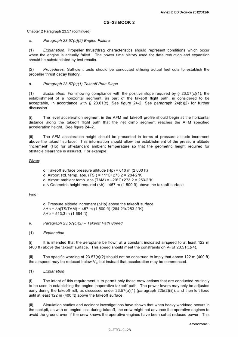
CS–23 BOOK 2
2–FTG–2–28
c. Paragraph 23.57(a)(2) Engine Failure
(1) Explanation. Propeller thrust/drag characteristics should represent conditions which occur when the engine is actually failed. The power time history used for data reduction and expansion should be substantiated by test results.
(2) Procedures. Sufficient tests should be conducted utilising actual fuel cuts to establish the propeller thrust decay history.
d. Paragraph 23.57(c)(1) Takeoff Path Slope
(1) Explanation. For showing compliance with the positive slope required by § 23.57(c)(1), the establishment of a horizontal segment, as part of the takeoff flight path, is considered to be acceptable, in accordance with § 23.61(c). See figure 242. See paragraph 24(b)(2) for further discussion.
(i) The level acceleration segment in the AFM net takeoff profile should begin at the horizontal distance along the takeoff flight path that the net climb segment reaches the AFM specified acceleration height. See figure 24–2.
(ii) The AFM acceleration height should be presented in terms of pressure altitude increment above the takeoff surface. This information should allow the establishment of the pressure altitude ‘increment’ (Hp) for offstandard ambient temperature so that the geometric height required for obstacle clearance is assured. For example:
Given:
o Takeoff surface pressure altitude (Hp) = 610 m (2 000 ft) o Airport std. temp. abs. (TS ) = 11°C+273.2 = 284.2°K o Airport ambient temp. abs.(TAM) = –20°C+273.2 = 253.2°K o ∆ Geometric height required (∆h) – 457 m (1 500 ft) above the takeoff surface
Find:
o Pressure altitude increment (∆Hp) above the takeoff surface ∆Hp = ∆h(TS/TAM) = 457 m (1 500 ft) (284.2°k/253.2°K) ∆Hp = 513,3 m (1 684 ft)
e. Paragraph 23.57(c)(2) – Takeoff Path Speed
(1) Explanation
(i) It is intended that the aeroplane be flown at a constant indicated airspeed to at least 122 m (400 ft) above the takeoff surface. This speed should meet the constraints on V2 of 23.51(c)(4).
(ii) The specific wording of 23.57(c)(2) should not be construed to imply that above 122 m (400 ft) the airspeed may be reduced below V2, but instead that acceleration may be commenced.
(1) Explanation
(i) The intent of this requirement is to permit only those crew actions that are conducted routinely to be used in establishing the engineinoperative takeoff path. The power levers may only be adjusted early during the takeoff roll, as discussed under 23.57(a)(1) (paragraph 22b(2)(ii)), and then left fixed until at least 122 m (400 ft) above the takeoff surface.
(ii) Simulation studies and accident investigations have shown that when heavy workload occurs in the cockpit, as with an engine loss during takeoff, the crew might not advance the operative engines to avoid the ground even if the crew knows the operative engines have been set at reduced power. This
Chapter 2 Paragraph 23.57 (continued)
Annex to ED Decision 2012/012/R
Amendment 3
Annex to ED Decision 2012/012/R
Amendment 3

CS–23 BOOK 2
2–FTG–2–29
same finding applies to manually feathering a propeller. The landing gear may be retracted, because this is accomplished routinely, once a positive rate of climb is observed. This also establishes the delay time to be used for data expansion purposes.
(2) Procedures
(i) To permit the takeoff to be based on a feathered propeller up to 122 m (400 ft) above the takeoff surface, automatic propeller feathering devices may be approved if adequate system reliability is shown in accordance with 23.1309. Other automatic systems such as one which minimises drag of the inoperative propeller by sensing negative torque may also be approved. Drag reduction for a manually feathered propeller is permitted for flight path calculations only after reaching 122 m (400 ft) above the takeoff surface.
(ii) For flap retraction above 122 m (400 ft) a speed of not less than the lesser of 1∙1 VMC or 1∙2VS1 should be maintained.
g. Paragraph 23.57(d) – Takeoff Path Construction
(1) Explanation. To take advantage of ground effect, AFM takeoff paths utilise a continuous takeoff path from VLOF to 11 m (35 ft), covering the range of power to weight ratios. From that point, free air performance, in accordance with 23.57(e), is added segmentally. This methodology may yield an AFM flight path that is steeper with the gear down than up. The aeroplane should not be banked before reaching a height of 15 m (50 ft) as shown by the net takeoff flight path. This requires determination of climb data in the wings level condition.
(2) Procedures. The AFM should include the procedures necessary to achieve this performance.
h. Paragraph 23.57(e)(2) – Takeoff Path Segment Conditions
(1) Explanation. Paragraph 23.57(e)(2) requires that the weight of the aeroplane, the configuration, and the power setting must be constant throughout each segment and must correspond to the most critical condition prevailing in the segment. The intent is that for simplified analysis, the performance be based on that available at the most critical point in time during the segment, not that the individual variables (weight, approximate power setting, etc.) should each be picked at its most critical value and then combined to produce the performance for the segment.
(2) Procedures. The performance during the takeoff path segments should be obtained using one of the following methods
(i) The critical level of performance as explained in paragraph 22h(1);
(ii) The actual performance variation during the segment.
i. Paragraph 23.57(d)(4) – Segmented Takeoff Path Check
(1) Explanation. None.
(2) Procedures. The takeoff path should be checked by continuous demonstrated takeoffs. A sufficient number of these, using the AFM established takeoff procedures and speeds and covering the range of powertoweight ratios, should be made to ensure the validity of the segmented takeoff path. The continuous takeoff data should be compared to takeoff data calculated by AFM data procedures but using test engine power and test speeds.
j. Turboprop Reduced Power Takeoffs
(1) Reduced takeoff power is a power less than approved takeoff power for which power setting and aeroplane performance is established by corrections to the approved power setting and
Chapter 2 Paragraph 23.57 (continued)
Annex to ED Decision 2012/012/R
Amendment 3
Annex to ED Decision 2012/012/R
Amendment 3

CS–23 BOOK 2
2–FTG–2–30
performance, when operating with reduced takeoff power, the power setting which establishes power for takeoff is not considered a limitation.
(2) It is acceptable to establish and use a takeoff power setting that is less than the approved takeoff power if:
(i) The establishment of the reduced power takeoff data is handled through the type certification process and contained in the AFM;
(ii) The reduced takeoff power setting:
(A) Does not result in loss of systems or functions that are normally operative for takeoff such as engine failure warning, configuration warning, autofeather, automatic throttles, rudder boost, automatic ignition, or any other safety related system dependent upon a minimum takeoff power setting.
(B) Is based on an approved engine takeoff power rating for which aeroplane performance data is approved.
(C) Does not introduce difficulties in aeroplane controllability or engine response/operation in the event that approved takeoff power is applied at any point in the takeoff path.
(D) Is at least 75% of the approved takeoff power.
(E) Is predicated on a careful analysis of propeller efficiency variation at all applicable conditions.
(iii) Relevant speeds used for reduced power takeoffs are not less than those which will show compliance with the required controllability margins with the approved takeoff power.
(iv) The AFM states, as a limitation, that reduced takeoff power settings may not be used:
(A) When the antiskid system (if installed) is inoperative.
(B) On runways contaminated with standing water, snow, slush or ice.
(C) On wet runways unless suitable performance accountability is made for the increased stopping distance on the wet floor.
(D) Where items affecting performance cause a significant increase in crew workload. Examples are inoperative equipment (e.g. inoperative engine gauges, reversers or engine systems resulting in the need for additional performance corrections) or nonstandard operations (i.e. any situation requiring a nonstandard takeoff technique).
(v) Procedures for determining and applying the reduced takeoff power value are simple, and the pilot is provided with information to obtain both the reduced power and approved takeoff power for each ambient condition.
(vi) The AFM provides adequate information to conduct a power check, using the approved takeoff power and if necessary, establish a time interval.
(vii) Procedures are given to the use of reduced power.
(viii) Application of reduced power in service is always at the discretion of the pilot.
Chapter 2 Paragraph 23.57 (continued)
Annex to ED Decision 2012/012/R
Amendment 3
Annex to ED Decision 2012/012/R
Amendment 3

CS–23 BOOK 2
2–FTG–2–31
23 PARAGRAPH 23.59 TAKEOFF DISTANCE AND TAKEOFF RUN
a. Takeoff Distance – Paragraph 23.59(a)
(1) Explanation. The takeoff distance is either of the two distances depicted in figure 23–1 and 23–2 and discussed in paragraph 23a(i) or (ii), whichever is greater. The distances indicated below are measured horizontally from the main landing gears at initial brake release to that same point on the aeroplane when the lowest part of the departing aeroplane is 11 m (35 ft) above the surface of the runway and accomplished in accordance with the procedures developed for 23.57.
(i) The distance measured to 11 m (35 ft) with a critical engine failure recognised at V1. See figure 23–1.
Takeoff Distance
Start V1 VLOF
11 m (35′)
Figure 23–1 TAKEOFF DISTANCE Critical Engine Failure Recognised at V1
(ii) One hundred fifteen percent (115%) of the distance measured to 11 m (35 ft) with all engines operating. See figure 23–2.
All Engine Distance
Start V LOF 11 m (35′)
Takeoff Distance = 1.15 * All Engine Distance to 11 m (35′)
Figure 23–2 TAKEOFF DISTANCE All Engines Operating
Chapter 2 (continued)
Annex to ED Decision 2012/012/R
Amendment 3
Annex to ED Decision 2012/012/R
Amendment 3

CS–23 BOOK 2
2–FTG–2–32
b. Takeoff Run – Paragraph 23.59(b)
(1) Explanation
(i) Takeoff run is a term used for the runway length when the takeoff distance includes a clearway (i.e. where the acceleratego distance does not remain entirely over the runway), and the takeoff run is either of the two distances depicted in figure 23–1 and 23–2 and discussed in paragraph 23b(1)(i)(A) or (B), whichever is greater. These distances are measured as described in 23.59(a). When using a clearway to determine the takeoff run, no more than onehalf of the air distance from VLOF to the 11 m (35 ft) point may be flown over the clearway. (A) The distance from start of takeoff roll to the midpoint between liftoff and the point at which the aeroplane attains a height of 11 m (35 ft) above the takeoff surface, with a critical engine failure recognised at V1. See figure 23–3.
Clearway Ground Roll
Takeoff Run Takeoff Distance
Midpoint Start V 1 V LOF 11m (35′)
Figure 23–3 TAKEOFF RUN – Critical Engine Failure Recognised at V1
(B) One hundred fifteen percent (115%) of the distance from start of roll to the midpoint between liftoff and the point at which the aeroplane attains a height of 11 m (35 ft) above the takeoff surface, with all engines operating. See figure 23–4.
Clearway 1.15 * Distance to Midpoint
Takeoff Run = Required Runway
Takeoff Distance = 1.15 * All Engine Distance to 11 m (35′)
Midpoint Start V LQF 11 m (35′)
Takeoff Path
Figure 23–4 TAKEOFF RUN – All Engines Operating
(ii) There may be situations in which the oneengineinoperative condition (paragraph 23b(1)(i)(A)) would dictate one of the distance criteria, takeoff run (required runway) or takeoff distance (required runway plus clearway) while the allengines operating condition (paragraph 23b(1)(i)(B)) would dictate the other. Therefore, both conditions should be considered.
(iii) For the purpose of establishing takeoff distances and takeoff runs, the clearway plane is defined in CS 1. The clearway is considered to be part of the takeoff surface, and a height of 11 m (35 ft) may be measured from that surface. See figure 23–5.
Chapter 2 Paragraph 23.59 (continued)
Annex to ED Decision 2012/012/R
Amendment 3
Annex to ED Decision 2012/012/R
Amendment 3

CS–23 BOOK 2
2–FTG–2–33
Clearway
11 m (35′)
Takeoff Path
Clearway Plane 1.25%
Maximum
Figure 23–5 CLEARWAY PROFILES
24 PARAGRAPH 23.61 TAKEOFF FLIGHT PATH
a. Takeoff Flight Path – Paragraph 23.61(a). The takeoff flight path begins 11 m (35 ft) above the takeoff surface at the end of the takeoff distance determined in accordance with 23.59 and ends when the aeroplane's height is the higher of 457 m (1 500 ft) above the takeoff surface or at an altitude at which the configuration and speed have been achieved in accordance with 23.67(c)(3). See figure 24–1.
b. Net Takeoff Flight Path – Paragraph 23.61(b) and (c)
(1) The net takeoff flight path is the actual path diminished by a gradient of 0.8 percent for two engine aeroplanes. See figure 24–2.
(2) The net takeoff flight path is the flight path used to determine the aeroplane obstacle clearance. Paragraph 23.61(b) states the required climb gradient reduction to be applied throughout the flight path for the determination of the net flight path, including the level flight acceleration segment. Rather than decrease the level flight path by the amount required by 23.61(b), 23.61(c) allows the aeroplane to maintain a level net flight path during acceleration but with a reduction in acceleration equal to the gradient decrement required by 23.61(b). By this method, the applicant exchanges altitude reduction for increased distance to accelerate in level flight in determination of the level flight portion of the net takeoff path.
Chapter 2Paragraph 23.59 (continued)
Annex to ED Decision 2012/012/R
Amendment 3
Annex to ED Decision 2012/012/R
Amendment 3

CS–23 BOOK 2
2–FTG–2–34
NOTE: The en route takeoff segment usually begins with the aeroplane in the en route configuration and with maximum continuous thrust, but it is not required that these conditions exist until the end of the takeoff path when compliance with 23.67(c)(3) is shown. The time limit on takeoff thrust cannot be exceeded.
* Segments as defined by 23.67.
Figure 24–1 TAKEOFF SEGMENTS AND NOMENCLATURE
11 m (35′)
11 m (35′)
Net Flight Path
Level from Takeoff Surface
Obstacle Clearance
≥122 m (400′)
Figure 24–2 NET TAKEOFF FLIGHT PATH
Chapter 2 Paragraph 23.61 (continued)
Takeoff flight path
Path 2
Height > 1500 feet
1500 feet
Height > 400 feet
Path 1 Heights are referenced to runway elevation at end of takeoff distance
35 Ft
V LOF V EF
Takeoff distance (longer of 1 eng inop takeoff
or 1.15 all eng takeoff)
Ground Roll 1ST 2ND Acceleration Final
Retracted Retraction Down
See note
See note
Retracting Enroute position
Maximum continuous
Takeoff
Takeoff Above 400 ft thrust can be reduced if the requirements of 23.57(c)(3) can be met with less than taxeoff thrust
Accelerating
1ST
V 2 Accelerating V Enroute
All operating One inoperative
Takeoff One autofeathered or windmilling One feathered
Up to 400 feet 400 feet or greater
Segment
Landing Gear
Flaps
Power
Airspeed
Engines
Propeller
*
Annex to ED Decision 2012/012/R
Amendment 3
Annex to ED Decision 2012/012/R
Amendment 3

CS–23 BOOK 2
2–FTG–2–35
25 PARAGRAPH 23.65 CLIMB: ALL ENGINES OPERATING
a. Explanation
(1) Objectives. The climb tests associated with this requirement are performed to establish the aeroplane's allengine performance capability for altitudes between sea level and not less than 3048 m (10 000 ft) with wing flaps set to the takeoff position. This is necessary to enable comparison with the minimum climb performance required, and also for AFM presentation of climb performance data of 3048 m (10 000 ft) and the effect of altitude and temperature (see 23.1587) and the effect of weight for a/c over 2 722 kg (6 000 lb) MTOW and Turbine Engined a/c.
(2) Cooling Climbs. Applicants with single engine reciprocating powered aeroplanes may vary the climb speeds to meet the requirements of 23.1047. If variations in climb speeds are required to meet the cooling tests, the applicant may wish to establish the variation of rate of climb with speed.
(3) Sawtooth Climbs. A common method of determining climb performance is sawtooth climbs. A series of climbs, known as sawtooth climbs, should be conducted at several constant indicated airspeeds using a constant power setting and a prescribed configuration. A minimum of three series of sawtooth climbs should be conducted. The mean altitudes through which the sawtooth climbs are conducted should be:
(i) As near sea level as practical.
(ii) Close to the ceiling (where 30 m (100 ft)/minute can be maintained) for sea level engines.
(iii) An intermediate altitude, taking into consideration the power characteristics of the engine.
b. Procedures – Sawtooth Climbs
(1) Climb Technique. With the altimeter adjusted to a setting of 1 013 mb (pressure altitude), the series of climbs should be initiated at a chosen altitude. Stabilise airspeed and power prior to recording data. The time at the beginning of each run should be recorded for weightaccounting purposes, and the stabilised climb should be continued for 3 minutes or 914 m (3 000 ft) minimum while holding airspeed substantially constant. Climbs should be conducted 90° to the wind, and alternately, on reciprocal headings to minimise the effects of windshear. Since the rate at which the altitude changes is the primary consideration of the test, particular care should be taken to observe the precise altimeter indication at precise time intervals. Time intervals of not more than 30 seconds are recommended for altimeter readings. Airspeed, ambient temperatures, r.p.m. and other engine power parameters also should be recorded, permissibly at longer intervals. Ratesofclimb/sink observed for test conditions should be greater than +/ 30 m (±100 ft.)/min. Rates of climb near zero tend to be unreliable. A running plot of altitudeversustime provides an effective means of monitoring acceptability of test data as the run progresses, and a running plot of the observed rate of climb obtained for each airspeed enables similar monitoring of the sawtooth program. This procedure is recommended because of the opportunity it affords for promptly observing and economically rectifying questionable test results.
(2) Air Quality. In order to obtain accurate results, it is essential that the sawtooth climbs be conducted in smooth air. In general, the effects of turbulence are more pronounced in test data obtained at lower rates of climb and, when testing for compliance with minimum climb requirements, even slight turbulence may produce errors in observed climbs of such magnitude as to render the data inconclusive with respect both to rate of climb and best climb speed. Less obvious but equally unacceptable for climb testing is the presence of an inverse gradient in the ambient temperature.
(3) Test Airspeeds. The airspeeds selected for the sawtooth climbs should bracket the best climb speed, which for preliminary purposes may be estimated as 140% of the poweroff stalling speed. The lowest climb test speed should be as near the stalling speed as can be flown without evidence of buffeting, or necessity for abnormally frequent or excessive control movements, which might penalise the climb performance. Although the example shown in figure 25–1 has 18.5 km/h (10 knot) intervals,
Chapter 2 (continued)
Annex to ED Decision 2012/012/R
Amendment 3
Annex to ED Decision 2012/012/R
Amendment 3

CS–23 BOOK 2
2–FTG–2–36
the interval between test speeds should be smaller at the low speed end of the range, and should increase as the speed increases. Suggested intervals are 9.3 km/h (5 knots) at the low end, varying to 27.8 km/h (15 knots) at the high end. In addition, the maximum level flight speed and VS (or VMIN) at the approximate midrange test altitude provide a useful aid in defining the curves in figure 25–2.
(4) Data Plotting. Sawtooth climb data is plotted on a graph using altitude and time as the basic parameters as shown in figure 25–1. After the sawtooth data has been plotted, draw in the mean altitude line. A tangent line can now be drawn to each of the sawtooth climb curves at the mean altitude intersection. By determining the slope of the tangent lines, the observed rate of climb at the mean altitude for each sawtooth can be determined.
Figure 25–1 OBSERVED DATA
(5) Data Corrections. For the density altitude method of data reduction (see appendix 2), it is necessary to correct the data to standard atmospheric conditions, maximum weight, and chart brake horsepower before proceeding any further with the observed data. These corrections sometimes change the observed data a significant amount. The maximum level flight speed (VMAX) data points should also be corrected to assist in defining the curves in figure 25–2.
(6) Plotting of Corrected Data. After the observed data has been corrected to the desired standards, it can be plotted as shown in figure 25–2 with the rate of climb versus calibrated airspeed at various density altitudes. It should be noted that the stall speed points are not usually true stabilised zero rate of climb data points. However, the stall speed points are useful in defining the asymptotic character of the left hand part of the curve.
(7) Speed Schedule Data Points. From the curves of figure 25–2, it is now possible to determine the aeroplane’s best rate of climb speed schedule, VY. This is done by drawing a straight line through the peaks (highest rate of climb point) of each of the previously drawn curves of R/C vs. CAS. Also, it is possible to obtain from this graph the best angle of climb speed schedule VX. This is done by drawing tangent lines to the R/C vs. CAS curves from the graph origin and connecting each of the tangent intersect points with a straight line. It should be noted that the VX and VY speed lines intersect at ‘zero’ rate of climb. This is because zero rate of climb occurs at the aeroplane’s absolute ceiling and VX, VY, VMIN, and VMAX are all the same speed at this point.
Chapter 2 Section 23.65 (continued) Chapter 2 Paragraph 23.65 (continued)
5200
4800
4400
4000
Tangent Mean ALT
130 K CAS
120 K CAS 110 K CAS 100 K CAS
90 K CAS
Pressurealtitude
V = 165 K CAS max
V = 72 K CAS min
Time minutes
Annex to ED Decision 2012/012/R
Amendment 3
Annex to ED Decision 2012/012/R
Amendment 3

CS–23 BOOK 2
2–FTG–2–37
Figure 25–2 RATE OF CLIMB VS. AIRSPEED
(8) Speed and Rate of Climb. Directly from information obtained from figure 25–2, it is possible to plot the climb performance of the aeroplane into a more usable form. By reading the rates of climb at the VY intersect points and plotting them against altitude as shown in figure 25–3, it is possible to determine the rate of climb from sea level to the absolute ceiling.
Figure 25–3 RATE OF CLIMB AND SPEEDS
Chapter 2 Paragraph 23.65 (continued)
1000
800
600
400
200
0
Rate of clim
b F
T/min
1250H D 4000H D 9200H D
V X V Y
Calibrated airspeed knots 0 20 40 60 80 100 120 140 160 180
15,000
10,000
Sea level
5,000 Density altitude
0 500 1,000 1,500
MP varying with altitude
SHP varying with altitude
Normaly aspirated engine
Constant SPH
Airspeed. KCAS Rate of climb
Constant MP
Turboprop engine
Turbochaged reci gin
p. En e
Normally aspirated recip. Engine
V X V Y
90 100
“” full throttle
Annex to ED Decision 2012/012/R
Amendment 3
Annex to ED Decision 2012/012/R
Amendment 3

CS–23 BOOK 2
2–FTG–2–38
(9) Cowl Flap and Mixture. Cowl flaps should be in the position used for cooling tests. The mixture setting should be set to that used during the cooling test.
(10) Weight and C.G. For climb performance tests, the aeroplane's test weight, load distribution and engine power should be recorded. Usually, forward c.g. is critical for climb performance.
c. Extrapolation of Climb Data. The climb data expansion required by 23.1587 from sea level to 3048 m (10 000 ft) and from ISA to ISA + 30°C can be accomplished by the methods in appendix 2. Normally, the same method used for data reduction should be used for data expansion. Use caution in extrapolating beyond altitudes that have not been verified by flight tests. Generally, data should not be extrapolated more than 914 m (3 000 ft) in altitude.
d. Special Equipment or Instrumentation. Climb performance tests require an airspeed indicator, sensitive altimeter, and total air temperature indicator with a known recovery factor. For reciprocating enginepowered aeroplanes, an induction air temperature gauge, engine tachometer, manifold pressure gauge and cylinder head temperature indicator may be appropriate. For turbinepowered aeroplanes, indicators of power parameters, such as torque meter, EGT, N1, N2, and propeller r.p.m., may be appropriate. A fuel counter and/or fuel flowmeter is useful. All instruments should be calibrated, and the calibration data should be included with the test records. In addition, a stopwatch and appropriate data recording board and forms are required.
e. Climb Performance After STC Modifications. (Reserved)
26 PARAGRAPH 23.66 TAKEOFF CLIMB, ONE ENGINE INOPERATIVE
(1) For normal, utility and aerobatic category reciprocating enginepowered aeroplanes greater than 2 722 kg (6 000 lb) and turbineengine powered aeroplanes in the normal, utility and aerobatic category, the propeller of the inoperative engine is required to be in the position it ‘rapidly and automatically assumes’ for the determination of oneengine inoperative takeoff climb performance. This allows performance credit for a reliable system which rapidly drives the propeller to a low drag setting with no action from the pilot. If no such system is fitted, the propeller should be assumed to be in the most critical condition.
27 PARAGRAPH 23.67 CLIMB: ONE ENGINE INOPERATIVE
a. Explanation
(1) Performance Matrix. For all twinengine aeroplanes, 23.67 requires the oneengine inoperative climb performance be determined in the specified configuration. The requirements of 23.67 are summarised in the following table:
Chapter 2 (continued) Chapter 2 Paragraph 23.65 (continued)
Annex to ED Decision 2012/012/R
Amendment 3
Annex to ED Decision 2012/012/R
Amendment 3

Annex to ED Decision 2012/012/R
Amendment 3
Annex to ED Decision 2012/012/R
Amendment 3

Regulation 23.67(a)(1) 23.67(a)(2) 23.67(b)(1) 23.67(b)(2) 23.67(c)(1) 23.67(c)(2) 23.67(c)(3) 23.67(c)(4) Category Normal, Utility & Aerobatic Commuter
Engine type and aeroplane weight kg (lb)
Recip. ≤2712(6 000) Recip. >2712(6 000) & Turbine –
VSO km/h (kt) >113 (61) ≤113 (61) – –
Power on operative engine
≤MCP ≤MCP MTOP ≤MCP MTOP MTOP ≤MCP MTOP
Configuration Flap and gear retracted
Flap and gear retracted
Takeoff flap, gear retracted
Flap and gear retracted
Takeoff flap, gear extended
Takeoff flap, gear retracted
Flap and gear retracted
Approach flap*, gear retracted
Propeller position on inoperative engine
Minimum drag Minimum drag Minimum drag Minimum drag
Position it automatically and rapidly assumes
Position it automatically and rapidly assumes
Minimum drag
Minimum drag
Attitude – – – – Wings level – – –
Climb speed ≥1.2VS1 ≥1.2VS1 Equal to that achieved at 15 m (50 ft) in the demonstration of 23.53
≥1.2VS1 V2 V2 ≥1.2VS1 As in procedures but ≥1.5VS1
Altitude m(ft) 1524(5 000) 1524(5 000) 122(400) 457(1 500) Takeoff surface
122(400) 457(1 500) 122(400)
Required climb gradient (%)
≥1.5 no minimum but must determine steady climb/descent gradient
Measurably positive
≥0.75 Measurably positive
≥2.0 ≥1.2 ≥2.1
*Approach position(s) in which VS1 does not exceed 110% of the VS1 for the related allenginesoperating landing positions
Annex to ED Decision 2012/012/R
Amendment 3
Annex to ED Decision 2012/012/R
Amendment 3

BOOK 2 CS–23
2–FTG–2–41
(2) Range of Tests. The primary objective of the climb tests associated with this requirement is to establish the aeroplane's climb performance capability with one engine inoperative for altitudes between sea level and 3048 m (10 000 ft) or higher and temperatures from ISA to ISA + 30°C. This is necessary to enable comparison with the prescribed climb requirement at 1524 m (5 000 ft) altitude, and also for AFM presentation of climb performance data for altitudes and temperatures as prescribed in 23.1587. Secondary objectives are to establish the climb speed to be used in the cooling tests required by 23.1041 through 23.1047, including the appropriate speed variation with altitude, and to establish a climb speed (or descent speed, as appropriate) which, irrespective of the speed used in demonstrating compliance with climb and cooling requirements, is required for presentation in the AFM in accordance with 23.1587(c)(5).
(3) WAT Charts. For aeroplanes with a MTOW greater than 2 722 kg (6 000 lb) and all turbine powered aeroplanes, a WAT chart is an acceptable means to meet the performance requirements. See discussion in paragraph 8 of this FTG.
b. Procedure
(1) Critical Engine. To accomplish these objectives, it is necessary that sawtooth climbs be conducted with the critical engine inoperative and with the prescribed configuration and power condition. The ‘criticalinoperativeengine’ for performance considerations is that engine which, when inoperative, results in the lowest rate of climb. The critical engine should be determined by conducting a set of sawtooth climbs, one engine at a time.
(2) Test Technique. Oneengineinoperative climb tests should be conducted at airspeeds and at altitudes as outlined for allengine climbs under 23.65. The test technique and other considerations noted under 23.65 also apply. In climb tests with one engine inoperative, however, trim drag can be a significant factor and oneengineinoperative climb tests should be conducted on a steady heading with the wings laterally level or, at the option of the applicant, with not more than 5° bank into the good engine in an effort to achieve zero sideslip. A yaw string or yaw vane is needed to detect zero sideslip. The AFM should describe the method used, and the approximate ball position required to achieve the AFM performance.
c. Commuter Category Aeroplanes
(1) Climb Gradient. The required climb gradients are specified in 23.67(c).
(2) Climb Performance Methods. Climb performance should be determined in the configurations necessary, to construct the net takeoff flight path and to show compliance with the approach climb requirements of 23.67(c). Some net takeoff flight path conditions will require wings level climb data. See paragraph 22g(1). If full rudder with wings level cannot maintain constant heading, small bank angles into the operating engine(s), with full rudder, should be used to maintain constant heading. For all other conditions, climb performance may be determined with up to 5° bank into the good engine. Two methods for establishing the critical oneengineinoperative climb performance follow:
(i) Method No. 1. Reciprocal heading climbs are conducted at several thrusttoweight conditions from which the performance for the AFM is extracted.
(ii) Method No. 2. Drag polars and engineout yaw drag data are obtained for expansion into AFM climb performance. See appendix 2. Reciprocal heading check climbs are conducted to verify the predicted climb performance.
(3) Landing Gear Position. The climb performance tests with landing gear extended in accordance with 23.67(c) should be conducted with the landing gear and gear doors extended in the most unfavourable intransit drag position. It has been acceptable to consider that the critical configuration is associated with the largest frontal area. For the landing gear, it usually exists with no weight on the landing gear. For gear doors, it is usually with all the gear doors open. If it is evident that a more critical transitional configuration exists, such as directional rotation of the gear, testing should be conducted in that configuration. In all cases where the critical configuration occurs during a
Chapter 2 Paragraph 23.67 (continued)
Annex to ED Decision 2012/012/R
Amendment 3
Annex to ED Decision 2012/012/R
Amendment 3

CS–23 BOOK 2
2–FTG–2–42
transition phase which cannot be maintained except by special or extraordinary procedures, it is permissible to apply corrections based on other test data or acceptable analysis.
(4) Cooling Air. If means, such as variable intake doors, are provided to control powerplant cooling air supply during takeoff, climb, and en route flight, they should be set in a position which will maintain the temperature of major powerplant components, engine fluids, etc. within the established limits. The effect of these procedures should be included in the climb performance of the aeroplane. These provisions apply for all ambient temperatures up to the highest operational temperature limit for which approval is desired.
(5) Power. See paragraph 22b.
28 PARAGRAPH 23.71 GLIDE (SINGLEENGINED AEROPLANES)
a. Explanation
(1) Gliding Performance. CS 2371 requires the optimum gliding performance to be scheduled, with the landing gear and wing flaps in the most favourable position and the propeller in the minimum drag position.
(2) Background. The primary purpose of this information is to provide the pilot with the aeroplane gliding performance. Such data will be used as an approximate guide to the gliding range that can be achieved, but will not be used to the same degree of accuracy or commercial significance as many other aspects of performance information. Hence some reasonable approximation in its derivation is acceptable.
b. Means of compliance
(1) EngineInoperative Tests. Clearly the simplest way of obtaining accurate data is to perform actual engineinoperative glides. These tests should be carried out over an airfield, thereby permitting a safe landing to be made in the event of the engine not restarting at the end of the test.
(i) Fixed Pitch Propeller. Most likely, the propeller will be windmilling after the fuel is shutoff. If this is the case and the propeller does not stop after slowing to the best glide speed, then the gliding performance should be based on a windmilling propeller. Stalling the aeroplane to stop the propeller from windmilling is not an acceptable method of determining performance because the procedure could cause the average pilot to divert attention away from the primary flight task of gliding to a safe landing.
(ii) Constantspeed / Variablepitch propeller aeroplanes. For these propellers, the applicant may assume that the means to change propeller pitch is still operational and therefore the propeller should be set at the minimum drag configuration. For most installations this will be coarse pitch or feather.
(2) Sawtooth Glides. If Sawtooth Glides are used to determine the glide performance, these glides can be flown using the same basic procedures in paragraph 23.65 of this guidance material. For simplification, the test need only be flown at an intermediate altitude and gross weight generating one speed for the pilot to use. The best lift over drag speed is frequently higher than the best rate of climb speed; therefore, the airspeed range to flight test may be bracketed around a speed 10 to 15% higher than the best rate of climb speed.
(3) Performance Data. A chart or table should be constructed for the AFM that presents the literal (overtheground) gliding distances for the altitude range expected in service, at the demonstrated glide speed. As a minimum, a statement of NMs per 305 m (1 000 ft) loss of altitude at the demonstrated configuration and speed at MTOW, standard day, no wind, has to be given.
Chapter 2 Paragraph 23.67 (continued)
Annex to ED Decision 2012/012/R
Amendment 3
Annex to ED Decision 2012/012/R
Amendment 3

BOOK 2 CS–23
2–FTG–2–43
29 PARAGRAPH 23.75 LANDING
a. Explanation
(1) Purpose. The purpose of this requirement is to evaluate the landing characteristics and to determine the landing distance. The landing distance is the horizontal distance from a point along the flight path 15 m (50 ft) above the landing surface to the point where the aeroplane has come to a complete stop, or to a speed of 5.6 km/h (3 knots) for seaplanes or amphibians on water.
(2) Companion Requirements. Paragraphs 23.143(a)(6), 23.153, 23.231, and 23.233 are companion requirements, and normally, tests to determine compliance would be accomplished at the same time. Additionally, the requirements of 23.473 should be considered.
(3) Approach and Landing. The steady gliding approach, the pilot skill, the conditions, the vertical accelerations, and the aeroplane actions in 23.75(a), (b), and (c) are concerned primarily with not requiring particularly skilful or abrupt manoeuvres after passing the 15 m (50ft) point. The phrase ‘steady gliding approach,’ taken in its strictest sense, means power off. However, it has generally been considered that some power may be used during a steady gliding approach to maintain at least 1.3 VS1 control sink rate on final approach. For those aeroplanes using power during approach, power may be decreased after passing the 15 m (50ft) point and there should be no nose depression by use of the longitudinal control. For those aeroplanes approaching with power off, the longitudinal control may be used as necessary to maintain a safe speed for flare. In both cases, there should be no change in configuration and power should not be increased. The landing distance and the procedure specified in the AFM are then based on the power used for the demonstration. The power used and the technique used to achieve the landing distances should be clearly stated in the AFM. This applies to portions of the approach prior to and after the 15 m (50ft) height. The aeroplane should be satisfactorily controllable when landing under the most unfavourable conditions to be encountered in service, including cross winds, wet runway surfaces and with one engine inoperative. Demonstration of landing with an adverse crosswind of at least 0.2 VS0 will be acceptable and operation on wet (but not contaminated) runway surfaces may be simulated by disconnecting nosewheel steering. The effect of weight on the landing distance due to its influence on controllability of reverse thrust should be considered.
(4) Landing Gear Loads. Sink rate at touchdown during landing distance determination should be considered and should not exceed the design landing gear loads established by 23.473(d).
(5) Landing Distance Credit for Disking Drag and Reverse Thrust. Most turboprop installations embody provisions for reduction of propeller blade pitch from the ‘flight’ regime to a ‘ground’ regime to produce a significant level of disking drag and/or reverse thrust following touchdown on landing. For purposes of this discussion, disking drag is defined as not less than zero thrust at zero airspeed. Paragraph 23.75(f) permits means other than wheel brakes to be used in determining landing distance, when the conditions specified in 23.75(f) are met. Such disking drag or reverse thrust may be acceptable in showing compliance with 23.75(f) provided the means is safe and reliable.
(i) Reliable. Compliance with the ‘reliable’ provision of the rule may be accomplished by an evaluation of the pitch changing/reversing system in accordance with 23.1309. The methods of AC 23.1309–1 should be used in the evaluation even though typecertificated engine or propeller systems may not have been subjected to the AC 23.1309–1 analysis during certification. Additionally, Society of Automotive Engineers (SAE) document ARP–926A, ‘Fault/Failure Analysis Procedure’, will assist in conducting reliability and hazard assessments.
For commuter category aeroplanes, 23.1309 requires the system to be designed to safeguard against hazards to the aeroplane in the event the system or any component thereof malfunctions or fails. An acceptable means for showing compliance with the requirement would be to conduct a Failure Modes and Effects Analysis (FMEA) of the system. An acceptable analysis would show that the effects of any system or component malfunction or failure would not result in a hazard to the aeroplane and that the propeller reversing system is reliable. SAE document, ARP–926A, ‘Fault/Failure Analysis Procedure’, contains acceptable criteria for conducting such an analysis.
Chapter 2 (continued)
Annex to ED Decision 2012/012/R
Amendment 3
Annex to ED Decision 2012/012/R
Amendment 3

CS–23 BOOK 2
2–FTG–2–44
Safe and reliable should also mean that it is extremely improbable that the system can mislead the flight crew or will allow asymmetric power settings, i.e. forward thrust on one engine vs. reverse thrust on the other. In achieving this level of reliability, the system should not increase crew work load or require excessive crew attention during a very dynamic time period in the landing phase. Also, the approved performance data should be such that the average pilot can duplicate this performance by following the AFM procedures.
(ii) Safe. Compliance with the ‘safe’ provisions of 23.75(f)(1) will require an evaluation of the complete system including operational aspects to ensure no unsafe feature exists.
(iii) Disking Drag for Twinengine Installations with Flight Idle and Ground Idle. Symmetrical power/thrust may be used, with power levers at flightidle position during air run, and at groundidle position after touchdown. Procedures for consistently achieving ground idle should be established to ensure that the operational pilot gets the power lever back to ground idle, and thus providing consistent results in service. Two of the designs that have been found acceptable for groundidle positioning are a dedicated throttle gate or tactile positioning of the throttle. In effecting thrust changes following touchdown, allowance should be made for any time delays that reasonably may be expected in service, or which may be necessary to assure that the aeroplane is firmly on the surface. See sub paragraph b(2) for commuter category time delays. Associated procedures should be included in the AFM. If the disking drag or some other powerplantrelated device has significant effect on the landing distance, the effect of an inoperative engine should be determined and published in the AFM Performance Section.
(iv) Disking Drag for SingleEngine Installations with Flight Idle and Ground Idle. Landing distances should be determined with the power levers at flightidle position during air run, and at groundidle position after touchdown. Procedures for consistently achieving ground idle should be established. Two of the designs that have been found acceptable for groundidle positioning are a dedicated throttle gate or tactile positioning of the throttle. In effecting thrust changes following touchdown, allowance should be made for any time delays that reasonably may be expected in service, or which may be necessary to assure that the aeroplane is firmly on the surface. Associated procedures should be included in the AFM.
(v) Reverse Thrust for Twinengine Aeroplanes. In the approval of reverse thrust for turboprop aeroplanes, due consideration should be given for thrust settings allowed, the number of operating engines, and control of the aircraft with one engine inoperative. If landing distance depends on the operation of any engine and if the landing distance would be noticeably increased (2% has been found acceptable) when a landing is made with that engine inoperative, the landing distance should be determined with that engine inoperative unless the use of compensating means (such as reverse thrust on the operating engine) will result in a landing distance not more than that with each engine operating (this assumes that there are no other changes in configuration, e.g. flap setting associated with one engine inoperative, that will cause an increase in landing distance). In effecting thrust changes following touchdown, allowance should be made for any time delays that reasonably may be expected in service, or which may be necessary to assure that the aeroplane is firmly on the surface. See sub paragraph b(2) for commuter category time delays. Associated procedures should be included in the AFM.
(vi) Reverse Thrust for SingleEngine Aeroplanes. In effecting thrust changes following touchdown, allowance should be made for any time delays that reasonably may be expected in service, or which may be necessary to assure that the aeroplane is firmly on the surface. Associated procedures should be included in the AFM.
(6) Balked Landing Transition. For the power conditions selected for the landing demonstration (except one engine inoperative) and other steady state conditions of speed and rate of sink that are established during the landing approach, it should be possible, at the 15 m (50ft) point, to make a satisfactory transition to the balked landing climb requirement of 23.77 using average piloting skill without encountering any unsafe conditions.
Chapter 2 Paragraph 23.75 (continued)
Annex to ED Decision 2012/012/R
Amendment 3
Annex to ED Decision 2012/012/R
Amendment 3

BOOK 2 CS–23
2–FTG–2–45
(7) Expansion of Landing Data for a Range of Airport Elevations. When the basic landing tests are accomplished between sea level and approximately 914 m (3 000 ft), the maximum allowable extrapolation limits are 1829 m (6 000 ft) above and 914 m (3 000 ft) below the test field elevation. If it is desired to extrapolate beyond these limits, one of two procedures may be employed. These procedures are given in paragraph 19c(3)(iii).
b. Procedures
(1) Technique. The landing approach should be stabilised on target speed, power, and the aeroplane in the landing configuration prior to reaching the 15 m (50ft) height to assure stabilised conditions when the aeroplane passes through the reference height. The engine fuel control should be adjusted to the maximum flightidle fuel flow permitted on aeroplanes in service unless it is shown that the range of adjustment has no effect on landing distance. A smooth flare should be made to the touchdown point. The landing roll should be as straight as possible and the aeroplane brought to a complete stop (or 5.6 km/h (3 knots) for seaplanes) for each landing test. Normal pilot reaction times should be used for power reduction, brake application, and use of other drag/deceleration devices. See subparagraph b(2) for commuter category time delays. These reaction times should be established by a deliberate application of appropriate controls as would be used by a normal pilot in service. They should not represent the minimum times associated with the reactions of a highly trained test pilot.
(2) Commuter Category Time Delays
(i) The time delays shown in figure 27–1 should be used.
(ii) For approved automatic deceleration devices (e.g. autospoilers, etc.) for which performance credit is sought for AFM data expansion, established times determined during certification testing may be used without the application of the 1second minimum time delay required in the appropriate segment above.
(3) Applicant's Procedures. The procedures to be followed should be those recommended by the applicant.
– This segment represents the flight test measured average time from touchdown to pilot actuation of the first deceleration device. For AFM data expansion, use 1 second or the test time, whichever is longer.
– This segment represents the flight test measured average test time from pilot actuation of the first deceleration device to pilot actuation of the second deceleration device. For AFM data expansion, see item above.
Step is repeated until pilot actuation of all deceleration devices has been completed and the aeroplane is in the full braking configuration.
Figure 27–1 LANDING TIME DELAYS
Chapter 2 Section 23.75 (continued) Chapter 2 Paragraph 23.75 (continued)
Transition from touchdown to full braking configuration
Touch down
Pilot actuation of first
deceleration device
Pilot actuation of second
deceleration device
Full braking configuration to stop
Stop
2 1
Annex to ED Decision 2012/012/R
Amendment 3
Annex to ED Decision 2012/012/R
Amendment 3

CS–23 BOOK 2
2–FTG–2–46
(4) Number of Landings. At least six landings should be conducted on the same wheels, tyres, and brakes to establish the proper functioning required by Part 21.35(b).
(5) Winds. Wind velocity and direction should be measured adjacent to the runway during the time interval of each test run. See paragraph 6a(5) of this FTG for wind velocity and direction tolerances.
(6) Weight. Landing tests should be conducted at maximum landing weight.
(7) Approach Angles Greater than 3°. If the applicant chooses an approach angle greater than 3°, landing distances which result from utilising a 3° approach angle should be determined and published in the AFM to enable operators to comply with related operational rules.
c. Data Acquisition
(1) The data to be recorded for landing distance tests are:
(i) Vertical and horizontal path of the aeroplane relative to the runway. Two methods that have been used are runway observers and time histories. Sink rate at touchdown and descent gradients may be computed from time histories.
(ii) Pressure altitude.
(iii) Ambient air temperature.
(iv) Aeroplane weight (fuel used or time since engine start). (v) Engine power or thrust data.
(vi) Cowl flap position.
(vii) Wing flap position.
(viii) Runway slope.
(ix) Direction of landing run.
(x) Wind direction and velocity at a height of 1.8 m (6 ft) adjacent to the runway near the touchdown point.
(xi) Landing procedures noted for inclusion in the AFM.
(2) Means of acquiring the required data are listed below:
(i) Time history data is obtained by use of a takeoff and landing camera, electronic equipment, or a phototheodolite having a known surveyed location. If landing gear loads are a concern, sink rate at touchdown may be computed, or alternately, vertical load factor may be measured by an accelerometer at the c.g..
(ii) Pressure altitude may be obtained with a calibrated sensitive altimeter.
(iii) Ambient air temperature should be obtained with a calibrated temperature sensor.
(iv) The aeroplane weight may be computed from a known weight at start of test minus the fuel used to the time of test.
(v) Engine power or thrust data may be determined using calibrated aeroplane powerplant instruments to provide the basic parameters required.
Chapter 2 Paragraph 23.75 (continued)
Annex to ED Decision 2012/012/R
Amendment 3
Annex to ED Decision 2012/012/R
Amendment 3

BOOK 2 CS–23
2–FTG–2–47
(vi) Cowl flap position may be obtained from a calibrated indicator or a measured position.
(vii) Wing flap position may be obtained from a calibrated indicator or a measured position.
(viii) Slope of the runway can be obtained from the official runway survey or other suitable data obtained using accepted survey practices.
(ix) Direction of the landing run will be the direction of the runway used, or an accurate compass indication.
(x) The wind direction and velocity should be obtained with an accurate compass and a calibrated anemometer. Wind data obtained from airport control towers should not be used.
30 PARAGRAPH 23.77 BALKED LANDING CLIMB
a. Explanation (Normal, Utility, and Aerobatic Category. Reciprocating Engined aeroplanes with a MTOW of 2 722 kg (6 000 lb) or less)
(1) Purpose. The configuration that is specified for this climb requirement ordinarily is used in the final stages of an approach for landing, and the objective of requiring the prescribed climb capability is to ensure that the descent may readily be arrested, and that the aeroplane will be able to ‘go around’ for another attempt at landing, in the event conditions beyond control of the pilot make such action advisable or necessary.
(2) Flap Retraction. As an alternative to having the flaps in the landing position, compliance with the balked landing climb requirement may be demonstrated with flaps in the retracted position, provided the flaps are capable of being retracted in 2 seconds or less and also provided the aeroplane's flight characteristics during flap retraction satisfy the constraints imposed by the regulation; that is, flaps must be retracted with safety, without loss of altitude, without sudden change in angle of attack, and without need for exceptional piloting skill. Evaluation should include satisfactory demonstration of ability to promptly arrest the descent by application of takeoff power in conjunction with rapid retraction of the flaps during final approach to landing.
(3) Flaps That Will Not Fully Retract in Two (2) Seconds. If the flaps will not fully retract in 2 seconds, the climb available with the flap position at the end of 2 seconds may be used as a consideration in an equivalent level of safety finding. Other considerations should include flight characteristics, ease of operation and reliability. If the flap is non mechanical, the flap mechanism should be reliable in order to receive credit for a partially retracted flap.
b. Procedures. Climb performance tests are conducted to establish compliance with the prescribed climb requirement and for inclusion in the AFM. The procedures outlined under 23.65 are equally applicable to the balked landing climb, except that the cooling and other considerations that recommend exploration of a speed range by conducting sawtooth climbs do not apply to the balked landing climb. In lieu of sawtooth climbs, the balked landing climb performance may be established as the average of not less than three continuous run pairs at the climb speed selected by the applicant.
c. Explanation. (Normal, Utility and aerobatic a/c with MTOW greater than 2 722 kg (6 000 lb) and turbine engined a/c and Commuter Category a/c). Paragraph 23.77(b)(1)(b) states that the engines are to be set at the power or thrust that is available 8 seconds after initiation of movement of the power controls from minimum flight idle to the takeoff position. The procedures given are for the determination of this maximum power for showing compliance with the climb requirements of 23.77.
d. Procedures. (A/c with a MTOW greater than 2 722 kg (6 000 lb). and Turbine Engined a/c)
(1) Engine Trim. Trim engines to the minimum idle speed/power to be defined in the aeroplane maintenance manual.
Annex to ED Decision 2012/012/R
Amendment 3
Annex to ED Decision 2012/012/R
Amendment 3

CS–23 BOOK 2
2–FTG–2–48
(2) Engine Power Tests. Engine power tests should be conducted at the most adverse landing elevation and temperature condition, or the range of landing altitude and temperature conditions if the most adverse cannot be readily determined.
(i) In the critical air bleed configuration, if applicable, stabilise the aeroplane in level flight with symmetrical power on all engines, landing gear down, flaps in the landing position, at a speed of VREF, at an altitude sufficiently above the selected test altitude so that time for descent to the test altitude with all throttles closed will result in minimum flightidle power at test altitude.
(ii) Retard throttles to flight idle and descend at VREF as defined in 23.73 to approximately the test altitude. When power has stabilised, advance throttle(s) in less than 1 second to obtain takeoff power.
(iii) The power that is available 8 seconds after the initiation of movement of the power controls from the minimum flight idle position is the maximum permitted for showing compliance with the landing climb of 23.77 for each of the bleed combinations tested.
(iv) If AFM performance is presented so there is no accountability for various bleed conditions, the power obtained with the most critical air bleed should be used for landing climb performance for all operations, including the effects of antiice bleed.
e. Data Acquisition and Reduction. The information presented under 23.65 applies to the balked landing climb.
31–38 RESERVED
Section 3 FLIGHT CHARACTERISTICS
39 PARAGRAPH 23.141 GENERAL
a. Explanation
(1) Minimum Flight Characteristics. The purpose of these requirements is to specify minimum flight characteristics which are considered essential to safety for any aeroplane. This paragraph deals primarily with controllability and manoeuvrability. A flight characteristic is an attribute, a quality, or a feature of the fundamental nature of the aeroplane which is assumed to exist because the aeroplane behaves in flight in a certain consistent manner when the controls are placed in certain positions or are manipulated in a certain manner. In some cases, measurements of forces, control surface positions, or acceleration in pitch, roll, and yaw may be made to support a decision but normally it will be a pass/fail judgement by the Agency test pilot.
(2) Exceptional Skills. The phrase ‘exceptional piloting skill, alertness, or strength’, is used repeatedly throughout the regulations and requires highly qualitative judgements on the part of the test pilot. The judgements should be based on the pilot’s estimate of the skill and experience of the pilots who normally fly the type of aeroplane under consideration (that is, private pilot, commercial pilot, or airline transport pilot skill levels). Exceptional alertness or strength requires additional judgement factors when the control forces are deemed marginal or when a condition exists which requires rapid recognition and reaction to be coped with successfully.
(3) Stall Speed Multipliers. For conventional configurations, all flying qualities and trim speeds may only be based on the forward c.g. stall speeds.
b. Procedures. None.
40–44 RESERVED
Chapter 2 Section 23.75 (continued) Chapter 2 (continued) Chapter 2 Paragraph 23.77 (continued)
Annex to ED Decision 2012/012/R
Amendment 3
Annex to ED Decision 2012/012/R
Amendment 3

BOOK 2 CS–23
2–FTG–2–49
Section 4 CONTROLLABILITY AND MANOEUVRABILITY
45 PARAGRAPH 23.143 GENERAL
a. Explanation
(1) Temporary Control Forces. Temporary application, as specified in the table, may be defined as the period of time necessary to perform the necessary pilot motions to relieve the forces, such as trimming or reducing power. The values in the table under 23.143 of CS 23 are maximums. There may be circumstances where a lower force is required for safety. If it is found that a lower force is necessary for safety, then that lower force should be established under Part 21.21(c)(3).
(2) Prolonged Control Forces. Prolonged application would be for some condition that could not be trimmed out, such as a forward c.g. landing. The time of application would be for the final approach only, if the aeroplane could be flown in trim to that point.
(3) Controllability. Controllability is the ability of the pilot, through a proper manipulation of the controls, to establish and maintain or alter the attitude of the aeroplane with respect to its flight path. It is intended in the design of the aeroplane that it be possible to ‘control’ the attitude about each of the three axes, the longitudinal, the lateral, and the directional axes. Angular displacements about the longitudinal axis are called ‘roll.’ Those about the lateral axis are called ‘pitch’ and those about the directional axis are called ‘yaw’. Controllability should be defined as ‘satisfactory’ or ‘unsatisfactory’. Unsatisfactory controllability would exist if the test pilot finds the controllability to be so inadequate that a dangerous condition might easily occur and is unacceptable as a showing of compliance with the regulations.
(4) Manoeuvrability. Manoeuvrability is the ability of the pilot, through a proper manipulation of the controls, to alter the direction of the flight path of the aeroplane. In order to accomplish this, it is necessary that the aeroplane be controllable, since a change about one of the axes is necessary in order to change a direction of flight. It should also be noted that any change in the direction of flight involves an acceleration normal to the flight path. Manoeuvrability is so closely related to controllability as to be inseparable in any real motion of the aeroplane. It is also similarly largely qualitative in its nature and should be treated in the same manner as has been suggested for controllability above.
(5) Spring Devices. If a spring device is installed in the control system, 23.687 requires that the aeroplane not have any unsafe flight characteristics without the use of the spring device, unless the reliability of the device can be established by tests simulating service conditions.
b. Procedures
(1) Landing. Using the AFM recommended approach/landing speeds and power settings, determine that aeroplane controllability is satisfactory with the wing flaps extended and retracted. These tests should be accomplished at the critical weight/c.g. combination within the allowable landing range. For turboprop aeroplanes, the engine fuel control should be adjusted to the minimum flightidle fuel flow permitted on aeroplanes in service unless it is shown that the range of adjustment permitted on aeroplanes in service has no measurable effect on flightidle sink rate.
(2) Other Flight Conditions. Controllability and manoeuvrability procedures for other flight conditions, such as takeoff and VMC, are covered in their respective sections.
(3) Lateral imbalance. Lateral imbalance flight evaluations should be conducted on all aeroplanes configured such that lateral trim and controllability may be affected. The following configurations should be considered and evaluated as appropriate:
(i) Takeoff – All engine, oneengineinoperative (twinengine aeroplanes), VMC, and crosswind operations.
Chapter 2 (continued)
Annex to ED Decision 2012/012/R
Amendment 3
Annex to ED Decision 2012/012/R
Amendment 3

CS–23 BOOK 2
2–FTG–2–50
(ii) En Route – All engine, oneengineinoperative (twinengine aeroplanes), and autopilot coupled operations.
(iii) Approach and Landing – All engine, one engine inoperative (twinengine aeroplanes), VMC
(where applicable), crosswind, and autopilot coupled operations.
As a result of flight tests, appropriate lateral imbalance limitations and procedures should be developed. Different values of imbalance for the various flight configurations may be required. Imbalance limits, if any, should be included in the AFM.
c. Data Acquisition and Reduction. A qualitative determination by the test pilot will usually suffice unless the control force limits are considered marginal. In this case, force gauges are used to measure the forces on each affected control while flying through the required manoeuvres.
46 PARAGRAPH 23.145 LONGITUDINAL CONTROL
a. Explanation
(1) Elevator Power. This regulation requires a series of manoeuvres to demonstrate the longitudinal controllability during pushovers from low speed, flap extension and retraction, and during speed and power variations. The prime determinations to be made by the test pilot are whether or not there is sufficient elevator power to allow pitching the nose downward from a minimum speed condition and to assure that the required manoeuvres can be performed without the resulting temporary forces becoming excessive.
(2) Speeds Below Trim Speeds. The phrase, ‘speeds below the trim speed’, as used in 23.145(a), means speeds down to VS1.
(3) Wing Flaps If gated flap positions are provided see paragraph 23.697.
(4) Loss of Primary Control Systems. Paragraph 23.145(e) is intended to cover a condition where a pilot has sustained some failure in the primary longitudinal control system of the aeroplane (for some twinengine aeroplanes, also loss of the directional control system) and is required to land using the power and trim system without the primary control. It is not intended that this test be demonstrated to an actual landing; however, a demonstration may be performed using manipulation of trim and power to a landing, if desired. 23.145(e) is the flight test to demonstrate compliance with the requirement which specifies a failure of the primary control system.
(5) Analysis of System. An analysis of the control system should be completed before conducting the loss of primary control system test. On some aeroplanes the required single longitudinal control system failure could result in loss of both the downspring and the primary longitudinal control system. If this failure occurred on an aeroplane utilising an extremely large downspring, the loss of the downspring may result in a noseup pitching moment at aft c.g. that could not be adequately countered by the basic pitch trim system.
b. Procedures. The wording of the regulation sufficiently describes the manoeuvres required to show compliance. The selection of altitudes, weights, and c.g. positions to be flight tested by the Agency will depend on a study of the applicant’s flight test report. Normally, the following combinations are checked during the certification tests:
(1) Altitude. A low altitude and an altitude near the maximum altitude capability of the aeroplane. A high altitude may not be needed for normally aspirated engine aeroplanes.
(2) Weight. Maximum gross weight for all tests, except where otherwise described in sub paragraph (3) below.
Chapter 2 Paragraph 23.143 (continued)
Annex to ED Decision 2012/012/R
Amendment 3
Annex to ED Decision 2012/012/R
Amendment 3

BOOK 2 CS–23
2–FTG–2–51
(3) C.G. For conventional configurations Paragraph 23.145(a), most aft c.g. and most aft c.g. approved for any weight; 23.145(b) 1 through 6, most forward and most aft c.g.; 23.145(c), most forward c.g.; 23.145(d), most forward c.g. and most forward c.g. approved for any weight; and 23.145(e), both the forward and aft c.g. locations. Paragraph 23.145(e) is sometimes more difficult to achieve at the aft c.g. than the forward limit, particularly if the aeroplane exhibits neutral to divergent phugoid tendencies.
(4) Power or Configuration. Pitching moments resulting from power or configuration changes should be evaluated under all conditions necessary to determine the most critical demonstration configuration.
c. Data Acquisition. No special instrumentation is required. The exception to this would be the 44.5 N (10 lbf) in 23.145(d) which should be measured with a force gauge. All longitudinal forces should be measured if the forces are considered marginal or excessive.
47 PARAGRAPH 23.147 DIRECTIONAL AND LATERAL CONTROL
a. Explanation
(1) Yawed Flight. Paragraph 23.147(a) is intended as an investigation for dangerous characteristics during sideslip, which may result from blocked airflow over the vertical stabiliser and rudder. Rudder lock and possible loss of directional control are examples of the kinds of characteristics the test is aimed at uncovering. Paragraph 23.177 also addresses rudder lock. Compliance may be demonstrated if the rudder stop is reached prior to achieving either 15° of heading change or the 667 N (150 lbf) limit providing there are no dangerous characteristics. The control stop serves more effectively than the 667 N (150 lbf) to limit the pilot’s ability to induce a yaw beyond that which has been demonstrated acceptable.
(2) Controllability following sudden engine failure. 23.147(b) requires a demonstration of controllability following sudden engine failure during enroute climb.
b. Procedures
(1) Yawed Flight. The aeroplane configurations to be tested according to 23.147(a) are:
(i) One engine inoperative and its propeller in the minimum drag position;
(ii) The remaining engines at not more than maximum continuous power;
(iii) The rearmost allowable centre of gravity;
(iv) The landing gear:
– Retracted; and – extended;
(v) The flaps retracted;
(vi) Most critical weight;
(vii) Aeroplane trimmed in the test condition, if possible.
(2) Controllability following sudden Engine Failure. In complying with the testing required by 23.147(b), from an initial climb condition of straight flight with wings level, zero sideslip and in trim simulate a sudden and complete failure of the critical engine. In order to allow for an appropriate delay no action should be taken to recover the aeroplane for two seconds following first indication of engine failure. The recovery action should not involve movement of the engine, propeller or trimming
Chapter 2 Paragraph 23.145 (continued)
Annex to ED Decision 2012/012/R
Amendment 3
Annex to ED Decision 2012/012/R
Amendment 3

CS–23 BOOK 2
2–FTG–2–52
controls. At no time until the completion of the manoeuvre should the bank angle exceed 45° or excessive yaw be developed. The evaluation of dangerous attitudes and characteristics should be based on each particular aeroplane characteristics and the flight test pilots evaluation.
The method used to simulate engine failure should be:
(i) for a reciprocating engine, closure of the mixture control; or
(ii) for a turbine engine, termination of the fuel supply by the means which results in the fastest loss of engine power or thrust. Engine shutoff procedures would normally be sufficient.
c. Loss of Primary Control Systems (see also AC 23.17)
(1) Explanation. Paragraph 23.147(c) is intended to cover a condition where a pilot has sustained some failure in the primary lateral control system of the aeroplane, and if a single failure in the primary lateral control system could also cause the loss of additional control, then the loss of the additional controls must be considered. It must be shown that with the loss of the primary lateral control that the aeroplane is safely controllable in all configurations and could be landed without exceeding the operational and structural limitations of the aeroplane. It is not intended that this test be demonstrated to an actual landing however, a demonstration may be performed using manipulations of lateral trim and or sideslip generated by the rudder and differential power, if available, to a landing. Paragraph 23.147(c) is the flight test to demonstrate compliance with the requirement which specifies a failure in the primary lateral control system. This failure implies a disconnection on the primary control system such that the ailerons are free to float and the lateral trim (if installed) is operational.
(2) Analysis of System. An analysis of the control system should be completed before conducting the loss of the primary lateral control test. On some aeroplanes the required single lateral control system failure could result in loss of a rudder aileron interconnect and perhaps loss of directional control as well as the primary lateral control. The most critical linkage failure of the primary lateral control system must be considered.
(3) Procedures. The wording of the regulation sufficiently describes the manoeuvres required to show compliance. The selection of altitudes, weights, c.g. position, lateral imbalance and aircraft configurations to be flight tested by the Agency will depend on the study of the applicants flight test report and whether the aircraft has a Lateral Trim System or not. Use of the Lateral Trim System to manoeuvre the aircraft and to hold wings level during an actual or simulated landing flare is authorised to comply with CS 23.147(c).
Those aircraft that do not have a separate and independent lateral trim system could use the rudder or differential power of a twin engine aircraft to generate a sideslip which would produce a rolling movement to control the bank angle. The use of rudder or asymmetric power to control bank angle implies that the aircraft exhibits lateral stability or dihedral effect. For those aircraft that use a rudder aileron interconnect to obtain lateral stability for which it is possible for a single failure in the primary lateral control system to disconnect the aileron rudder interconnect, compliance with CS 23.147(c) must be performed for the most critical case. If compliance with the continued safe flight provisions of CS 23.147(c) can only be demonstrated with flap, speed, power and/or procedures, these procedures should be noted in the Aircraft Flight Manual, in the Emergency Section.
i. Altitude. A low altitude and an altitude near the maximum capability of the aeroplane. The high altitude test is to determine controllability with decreased Dutch roll damping.
ii. Weight. Maximum gross weight for all tests except where otherwise described in sub paragraph (3) below.
iii. C.G. For conventional configuration paragraph 23.147(a) the most aft c.g. is critical, if the rudder is used to roll the aeroplane. For unconventional configurations the most critical c.g. must be used.
Chapter 2 Paragraph 23.147 (continued)
Annex to ED Decision 2012/012/R
Amendment 3
Annex to ED Decision 2012/012/R
Amendment 3

BOOK 2 CS–23
2–FTG–2–53
iv. Lateral Imbalance. The maximum lateral imbalance for which certification is requested must be used when flight testing for compliance with Paragraph 147(c).
v. Configuration, Power and Speed. Lateral controllability must be demonstrated with all practicable configurations and speeds. The maximum flaps used to demonstrate an actual or simulated landing need not be the maximum deflection possible.
48 PARAGRAPH 23.149 MINIMUM CONTROL SPEED
a. Background. Paragraph 23.149 requires the minimum control speed to be determined. Paragraph 23.1545(b)(6) requires the airspeed indicator to be marked with a red radial line showing the maximum value of oneengineinoperative minimum control speed. Paragraph 23.1583(a)(2) requires that VMC be furnished as an airspeed limitation in the AFM. These apply only to twinengine aeroplanes. A different VMC airspeed will normally result from each approved takeoff flap setting. There are variable factors affecting the minimum control speed. Because of this, VMC should represent the highest minimum airspeed normally expected in service. The variable factors affecting VMC testing include:
(1) Engine Power. VMC will increase as power is increased on the operating engine(s). Engine power characteristics should be known and engine power tolerances should be accounted for.
(2) Propeller of the Inoperative Engine. Windmilling propellers result in a higher VMC than if the propeller is feathered. VMC is normally measured with propeller windmilling unless the propeller is automatically feathered or otherwise driven to a minimum drag position (e.g. NTSSystem) without requiring pilot action.
(3) Control Position. The value of VMC is directly related to the control surface travel available. Normally, VMC is based on available rudder travel but may, for some aeroplanes, be based on aileron travel. For these reasons, VMC tests should be conducted with rudder and aileron (if applicable) controls set at minimum travel. In addition, rudder and aileron control cable tensions should be adjusted to the minimum production tolerances. If during VMC tests, control force limits would be exceeded at full deflection, then a lesser deflection should be used so as not to exceed §23.143 force limits.
(4) Weight and C.G. For rudder limited aeroplanes with constant aft c.g. limits, the critical loading for VMC testing is most aft c.g. and minimum weight. Aft c.g. provides the shortest moment arm relative to the rudder and thus the least restoring moments with regard to maintaining directional control. VMC should be determined at the most adverse weight. Minimum practical test weight is usually the most critical, because the beneficial effect of banking into the operating engine is minimised. Light weight may be necessary for VMC testing, because the stall speed is reduced.
(5) Lateral Loading. The maximum allowable adverse lateral imbalance (fuel, baggage etc.) should be maintained.
b. Explanation
(1) Controllability. The determination of VMC is closely related to the controllability requirements. It is one of the manoeuvres which generally requires maximum rudder and/or maximum aileron deflection (unless limited by temporary control forces) to maintain aeroplane control. When minimum control speed is determined using maximum rudder deflection, limited aeroplane manoeuvring is still available using the ailerons and elevator. When minimum control speed is determined using maximum aileron deflection, the aeroplane may be incapable of further manoeuvring in the normal sense.
(2) Critical Engine. The regulation requires that VMC determination be made ‘when the critical engine is suddenly made inoperative’. The intent is to require an investigation to determine which engine is critical from the standpoint of producing a higher VMC speed. This is normally accomplished during static VMC tests.
Chapter 2 Paragraph 23.147 (continued)
Annex to ED Decision 2012/012/R
Amendment 3
Annex to ED Decision 2012/012/R
Amendment 3

CS–23 BOOK 2
2–FTG–2–54
(3) Straight Flight. Straight flight is maintaining a constant heading. Paragraph 23.149(a) requires the pilot to maintain straight flight (constant heading). This can be accomplished either with wings level or, at the option of the applicant, with up to 5° of bank toward the operating engine. Normally, 2– 3° of bank allows the aeroplane to attain zero sideslip so that at 5° bank, the beneficial effects of directional stability to counter the yaw produced by asymmetric thrust can be utilised.
(4) Control Forces. The rudder and aileron control force limits may not exceed those specified in 23.143.
(5) Deicer Boots, Antennas and other External Equipment. The installation of deicer boots, antennas, and other external gear could change the VMC speed significantly. Reevaluation of the VMC
speed should be considered when these installations are made. See AC 23.1419–2 if a ‘flight into icing’ approval is being sought.
(6) Variable VMC. For reciprocating enginepowered aeroplanes of more than 2 722 kg (6 000 lb) maximum weight and for turbineengine powered aeroplanes, a VMC which varies with altitude and temperature is a permissible condition for use in determining 23.51 takeoff speeds, provided that the AFM does not show a VR below the red radial line speed required by 23.1545(b)(6).
(7) Autofeather Annunciations. If autofeather is installed, there should be annunciations to advise of the status. This will include at least green advisory anytime the system is armed. For some aeroplanes, the autofeather system will be identified as a critical system. This could be because VMC
has been determined with an operative autofeather system or because commuter category takeoff conditions were predicated on an operative autofeather system. For such installations, additional annunciations may be necessary to ensure that the system is armed and that malfunctions are immediately recognised. This could include caution/warning/advisory annunciations as follows:
(i) Caution or warning, if autofeather switch is not armed.
(ii) Caution or advisory if the autofeather is armed, then is subsequently disarmed because of a system malfunction.
All annunciations should be evaluated to verify that they can be easily and quickly recognised. For critical systems, the AFM limitations should require a satisfactory preflight check and that the autofeather be armed for takeoff and landing.
c. Procedures
(1) Configuration. Prior to conducting VMC tests, rudder and aileron control travels should be set to the minimum allowable production travels. Rudder and aileron control cable tensions should be adjusted to the minimum value for use in service. The critical loading for VMC testing is generally minimum weight and maximum aft c.g.; however, each aeroplane design should be evaluated independently to be assured that tests are conducted under the critical loading conditions. Variable aft c.g. limits as a function of weight, tip tanks, etc., can cause the critical loading condition to vary from one aeroplane to another.
(2) Power. An aeroplane with a sealevel engine will normally not be able to produce rated takeoff power at the higher test altitudes. Under these circumstances, VMC should be determined at several power settings and a plot of VMC versus power will allow extrapolation to determine VMC at maximum takeoff power. See subparagraph c(6) for a further explanation of extrapolation methods. If tests are conducted at less than approximately 914 m (3 000 ft) density altitude, no corrections to VMC
are normally necessary. If tests are conducted above 914 m (3 000 ft) density altitude, then additional tests should be conducted to allow extrapolation to sea level thrust. Because propeller thrust decreases with increasing true airspeed, VMC will increase with decreasing altitude and temperature, even at constant power.
Chapter 2 Paragraph 23.149 (continued)
Annex to ED Decision 2012/012/R
Amendment 3
Annex to ED Decision 2012/012/R
Amendment 3

BOOK 2 CS–23
2–FTG–2–55
The results of testing are used to predict the VMC for a maximum takeoff power condition at sea level unless, because of turbocharging or other reasons, some higher altitude prevails as the overall highest VMC value.
(3) Propeller Controls. All propeller controls have to stay in the recommended takeoff or approach position as appropriate throughout the whole procedure.
(4) Flap Settings. An applicant may want to specify more than one takeoff or landing flap setting as appropriate which would require VMC investigation at each flap setting.
(5) Stalls. Extreme caution should be exercised during VMC determination due to the necessity of operating with asymmetric power, full rudder and aileron at speeds near the aerodynamic stall. In the event of inadvertent entry into a stall, the pilot should immediately reduce the pitch attitude, reduce power on the operating engine(s) and return rudder and aileron controls to neutral to preclude possible entry into a spin.
(6) Static Minimum Control Speed. The test pilot should select test altitude based on the capability to develop takeoff power and consistent with safe practices. It will be necessary to determine which engine is critical to the VMC manoeuvre by conducting static tests with first one then the other engine inoperative to discover which produces the higher VMC. Power should be set to the maximum available for the ambient condition. Test weights should be light enough to identify the limits of directional control without stalling or being in prestall buffet.
For each test altitude condition, the following should be accomplished:
(i) Flaps and Gear. For the Takeoff conditions, the gear should be retracted and the flaps in the Takeoff position(s). For the landing conditions the gear should be extended and the flaps in the landing position(s).
(ii) Trim. The aeroplane should be trimmed to the settings associated with normal symmetrical power takeoff or approach as appropriate with all engines operating, as indicated.
(iii) Power. Render the one engine inoperative and set takeoff power on the other engine. The propeller on the inoperative engine should be windmilling, or in the condition resulting from the availability of automatic feathering or other devices.
(iv) Test Techniques. Gradually reduce airspeed until it is no longer possible to prevent heading changes with maximum use of the directional and/or maximum use of the lateral controls, or the limit control forces have been reached. No changes in lateral or directional trim should be accomplished during the speed reduction. Usually the 5° bank option will be used (see paragraph 48b(3)) to maintain straight flight. A yaw string may be used to assist the test pilot in attaining zero sideslip (or minimum sideslip).
(v) Critical Engine. Repeat steps (i) through (iv) to identify which inoperative engine results in the highest minimum control speed.
(7) Extrapolation to Sea Level. The only VMC test data that can be extrapolated reliably are static VMC data, where most of the variables can be carefully controlled to a constant value. Because VMC
data are typically collected in ambient conditions less critical than sea level standard day, extrapolation is nearly always necessary. Therefore, the usual way to establish an AFM VMC is to extrapolate static VMC data. When VMC is determined for an aeroplane with an automatically feathered propeller, special techniques may be required. Appendix 3 shows one method for extrapolating static VMC from test conditions to sea level standard day.
(8) Dynamic Minimum Control Speed. After determining the critical engine static VMC, and at some speed above static VMC, make a series of engine cuts (using the mixture control or idle cutoff control) dynamically while gradually working speed back toward the static speed. While maintaining this speed after a dynamic engine cut, the pilot should be able to control the aeroplane and maintain
Chapter 2 Paragraph 23.149 (continued)
Annex to ED Decision 2012/012/R
Amendment 3
Annex to ED Decision 2012/012/R
Amendment 3

CS–23 BOOK 2
2–FTG–2–56
straight flight without reducing power on the operating engine. During recovery, the aeroplane should not assume any dangerous attitude nor should the heading change more than 20° when a pilot responds to the critical engine failure with normal skill, strength, and alertness. The climb angle with all engines operating is high, and continued control following an engine failure involves the ability to lower the nose quickly and sufficiently to regain the initial stabilised speed. The dynamic VMC
demonstration will normally serve as verification that the numbers obtained statically are valid. If, in fact, the dynamic case is more critical, then the extrapolated static VMC value should be increased by that increment. Frequently, the dynamic VMC demonstration will indicate a lower VMC than is obtained from static runs. This may be due to the fact that the inoperative engine, during spooldown, may provide net thrust or that control force peaks exceed limit values for a short period and go undetected or that due to high yaw and pitch angles and rates, the indicated airspeed values are erroneous. Because of the twinvariable nature of the dynamic VMC demonstration, the AFM VMC value should represent the highest of the static or dynamic VMC test data, corrected to critical conditions. Specially in test conditions with a high thrust/weight ratio, a modified procedure may be applied to avoid extreme pitch attitudes. In this case decelerate to below VMC, all engines, accelerate with 2 x MTOP to a representative climb pitch attitude, cut the critical engine at static VMC (verify before that VMC is acceptably above actual stall speed).
(9) Repeatability. Once determined, and if the dynamic VMC seems to be the critical one, the dynamic VMC should be verified by running a series of tests to determine the speed is repeatable.
(10) AFM Minimum Control Speed Value. VMC is usually observed at several different power settings and/or altitudes. Sufficient test data should be obtained such that the VMC for the highest power and sea level density conditions may be determined. The VMC resulting from this extrapolation to sea level is the one entered into the AFM and marked on the airspeed indicator. If this VMC is determined with an autofeather system, the AFM required equipment list, as well as the Kind of Operation List (KOEL), should list autofeather as a required item and the AFM may state the VMC with the autofeather system inoperative (propeller windmilling) in the abnormal/emergency procedures section. The normal procedures section should also require the autofeather to be armed (if applicable) during takeoff and landing.
(d) Safe, Intentional, OneengineInoperative Speed, VSSE (RESERVED).
49 PARAGRAPH 23.151 AEROBATIC MANOEUVRES
a. Explanation. This regulation requires each manoeuvre to be evaluated and safe entry speeds established. Paragraph 23.1567(c), which is associated with this requirement, imposes a requirement for a placard which gives entry airspeeds and approved manoeuvres. If inverted flight is prohibited, the placard should so state.
b. Procedures. The applicant should fly each manoeuvre for which approval is sought. The Agency test pilot should then evaluate those manoeuvres considered most critical.
c. Data Acquisition. A recently calibrated airspeed system, airspeed indicator, accelerometer, and tachometer should be provided by the applicant for the test aeroplane. The following should be recorded:
(1) Load factor.
(2) Entry airspeeds.
(3) Maximum airspeeds.
(4) Maximum r.p.m.
50 PARAGRAPH 23.153 CONTROL DURING LANDINGS
a. Explanation
Chapter 2 Paragraph 23.149 (continued) Chapter 2 Paragraph 23.149 (continued)
Annex to ED Decision 2012/012/R
Amendment 3
Annex to ED Decision 2012/012/R
Amendment 3

BOOK 2 CS–23
2–FTG–2–57
(1) Purpose. The purpose of this requirement is to ensure that aeroplanes do not encounter excessive control forces when approaching at a speed of 9.3 km/h (5 knots) lower than normal landing approach speed, also, a safe landing is required. Safe is considered to include having sufficient flare capability to overcome any excessive sink rate that may develop.
(2) Landing Requirements. Paragraph 23.75 is a companion requirement and normally tests to determine compliance would be accomplished at the same time.
b. Procedures. The procedures applicable to 23.75 would apply for 23.153 except that for turbopropeller aeroplanes, the flightidle fuel flow should be adjusted to provide minimum thrust.
51 PARAGRAPH 23.155 ELEVATOR CONTROL FORCE IN MANOEUVRES
a. Explanation
(1) Stick Force Per G. The purpose of this requirement is to ensure that the positive stick force per g levels in a cruise configuration are of sufficient magnitude to prevent the pilot from inadvertently overstressing the aeroplane during manoeuvring flight. The minimum manoeuvring stability levels are generally found at aft c.g. loadings. Both aft heavy and aft light loadings should be considered. During initial inflight investigations, caution should be exercised in the event that pitchup tendencies or decreasing stick force per g conditions occur.
(2) Buffet Boundaries. Low speed buffet onset may occur during high altitude investigations. A qualitative evaluation should be conducted beyond the boundary of buffet onset to ensure a capability to manoeuvre out of the buffet regime.
b. Procedures. Compliance with the requirements of 23.155 may be demonstrated by measuring the normal acceleration and associated elevator stick force in a turn while maintaining the initial level flight trim speed. A descent may be required in the turn to maintain the level flight trim speed. As a minimum, the following conditions should be investigated in the cruise configuration; that is, flaps up and gear up (if retractable):
Condition Power Wings Level Trim Speed
Altitude
1 See note Trimmed (but not to exceed VNE or VMO/MMO)
Low
2 See note Trimmed Altitude for highest dynamic pressure (q)
3 See note VA Low
4 See note VA Highest attainable approved altitude
NOTE: 75% maximum continuous power (reciprocating engine) or maximum continuous power (turbine).
Annex to ED Decision 2012/012/R
Amendment 3
Annex to ED Decision 2012/012/R
Amendment 3

CS–23 BOOK 2
2–FTG–2–58
Compliance may be demonstrated by measuring the normal acceleration achieved with the limiting stick force (222 N (50 lbf) for wheel controls, 156 N (35 lbf) for stick controls) or by establishing the stick force per g gradient and extrapolating to the appropriate limit. Linear stick force gradients may be extrapolated up to 0.5 g maximum. Nonlinear stick force gradients that indicate a possible gradient lightening at higher g levels should not be extrapolated more than 0.2 g.
c. Data Acquisition and Reduction. The following should be recorded for each test condition:
(1) Wt./c.g.
(2) Pressure altitude.
(3) Outside air temperature (OAT).
(4) Engine power parameters.
(5) Trim setting.
(6) Elevator force.
(7) Normal acceleration at c.g.
(8) Gear/flap position.
The test data should be presented in stick force versus g plots. Figure 51–1 shows a sample plot. Test results should be compared to the requirements of 23.155(a).
Figure 51–1 STICK FORCE PER G
Chapter 2 Paragraph 23.155 (continued)
50
40
30
20
10
0
LBS pull
0.5 1.0 1.5 2.0 2.5 3.0 3.5 4.0
CAS=
c.g.=
Normal acceleration G’s
Annex to ED Decision 2012/012/R
Amendment 3
Annex to ED Decision 2012/012/R
Amendment 3

BOOK 2 CS–23
2–FTG–2–59
d Stick Force per G. 23.155(c) An increase in pull force should be required to produce an increase in normal acceleration throughout the range of required load factor and speed. Any reduction in control force gradient with change in load factor should not be so large or abrupt as to significantly impair the ability of the pilot to maintain control of normal acceleration and pitch rate. The local value of control force gradient should not be less than 13 N (3 lbf)/g for stickcontrolled aeroplanes or 18 N (4 lbf)/g for wheelcontrolled aeroplanes. The elevator control force should increase progressively with increasing load factor.
Flight tests to satisfy the above must be performed at sufficient points to establish compliance with 23.155(c) throughout the normal flight envelope. During these tests the load factor should be increased until either:
(1) the intensity of buffet provides a strong and effective deterrent to further increase of load factor; or
(2) further increase of load factor requires an elevator control force in excess of 667 N (150 lbf) for a wheel control or 556 N (125 lbf) for a stick control or is impossible because of the limitations of the control system; or
(3) the positive limit manoeuvring load factor is achieved.
52 PARAGRAPH 23.157 RATE OF ROLL
a. Explanation. The purpose of this requirement is to ensure an adequately responsive aeroplane in the takeoff and approach configuration.
b. Procedures
(1) Bank Angle. The aeroplane should be placed in a 30° bank and rolled through an angle of 60°. For example, with the aeroplane in a steady 30° left bank, roll through a 30° right bank and measure the time. Paragraphs 23.157(b) and (d) should be accomplished by rolling the aeroplane in both directions.
(2) Controls. Paragraphs 23.157(a) and (c) permit using a favourable combination of controls. The rudder may be used as necessary to achieve a coordinated manoeuvre.
(3) Weight. The ‘W’ in the formulas is the maximum Takeoff weight.
53–62 RESERVED
Section 5 TRIM
63 PARAGRAPH 23.161 TRIM
a. Explanation. The trim requirements ensure that the aeroplane will not require exceptional skill, strength, or alertness on the pilot's part to maintain a steady flight condition. The tests require the aeroplane to be trimmed for handsoff flight for the conditions specified. It should be noted that for singleengine aeroplanes, lateraldirectional trim is required at only one speed and thus, ground adjustable tabs are acceptable. For lateraldirectional testing, the tabs may be adjusted for the test trim airspeed and readjusted for subsequent tests. For twinengine aeroplanes, directional trim is required for a range of speeds. Lateral baggage loading and fuel asymmetry should be considered in this evaluation, if appropriate.
b. Procedures
Chapter 2 Paragraph 23.155 (continued)
Annex to ED Decision 2012/012/R
Amendment 3
Annex to ED Decision 2012/012/R
Amendment 3

CS–23 BOOK 2
2–FTG–2–60
(1) Actuator Settings. Trim actuator travel limits should be set to the minimum allowable.
(2) Altitude and Power. Tests for trim should be conducted in smooth air. Those tests requiring use of maximum continuous power should be conducted at as low an altitude as practical to ensure attaining the required power.
(3) Weight and C.G. Longitudinal trim tests should be conducted at the most critical combinations of weight and c.g.. Forward c.g. is usually critical at slow speeds, and aft c.g. critical at high speeds.
64–69 RESERVED
Section 6 STABILITY
70 PARAGRAPH 23.171 GENERAL
a. Explanation
(1) Required Stability. The stability portion of CS 23 is primarily concerned with static stability. No quantitative values are specified for the degree of stability required. This allows simple test methods or qualitative determinations unless marginal conditions are found to exist. The regulations merely require that the aeroplane be stable and that it have sufficient change in control force, as it is displaced from the trimmed condition, to produce suitable control feel for safe operation.
(2) Forces. The magnitude of the measured forces should increase with departure from the trim speed up to the speed limits specified in 23.175 or up to the 178 N (40 lbf) force limit specified in 23.173. The stick force variation with speed changes should be stable, i.e. a pull force required to fly slower than trim and a push force required to fly faster than trim and the gradient should be clearly perceptible to the pilot at any speed between 1.3 VS1 and VNE or VFC/MFC. Fig 70.1 below shows an example of cruise configuration.
FRSR + > 40 KTS or 15% VT
F.R.S.R
V i
FRSR + > 40 KTS OR 15% V T
TRIM V
Pull (+)
Push ()
Fe
Figure 70–1 STATIC LONGITUDINAL STABILITY DATA
Speed Range = Greater of + 74 km/h (40 kts) or 15% Vtrim + free return speed range (FRSR)
At speeds below 1.3 VS1 for normal, utility and aerobatic aeroplanes and at speeds below 1.4 VS1 for commuter aeroplanes, the slope need not be stable, see Fig 70.2 and 70.3. The pull forces can decrease in magnitude with speed decrease down to but not including the stall speed VS1, however, the pull force should in no case fall below zero before the stall is reached. Instrumented force measurements are required if there is any uncertainty in the qualitative assessment of the force gradients.
Chapter 2 Section 23.161 (continued) Chapter 2 Paragraph 23.161 (continued)
Annex to ED Decision 2012/012/R
Amendment 3
Annex to ED Decision 2012/012/R
Amendment 3

BOOK 2 CS–23
2–FTG–2–61
Figure 70–2 LOW SPEED INSTABILITIES: (i) Normal, Utility and Aerobatic Aircraft
Figure 70–3 (ii) Commuter Aircraft
b. Procedures. None required for this paragraph.
FRSR + > 40 KTS or 15% V T
TRIM V
V i
Pull
Push
Fe
V 1+3 V S1 V S1
FRSR + 50 KTS
Pull
V i
Push
Fe
TRIM V
SI
1+4 VS1
V SI
Annex to ED Decision 2012/012/R
Amendment 3
Annex to ED Decision 2012/012/R
Amendment 3

CS–23 BOOK 2
2–FTG–2–62
71 PARAGRAPH 23.173 STATIC LONGITUDINAL STABILITY
a. Explanation
(1) Demonstration Conditions. The general requirements of 23.173 are determined from a demonstration of static stability under the conditions specified in 23.175.
(2) Control Frictions. Paragraph 23.173(b) effectively limits the amount of control friction that will be acceptable since excessive friction would have a masking effect on stability. If autopilot or stability augmentation systems are of such a design that they tend to increase the friction level of the longitudinal control system, critical static longitudinal stability tests should be conducted with the system installed. Control cable tensions should be set to the maximum.
x = FRSR + (> 74 km/h (40 kt) or 15% VTRIM)
Figure 70–4
(3) Stable Slope. Paragraph 23.173(c) is an extremely general requirement which requires the test pilot's best judgement as to whether or not the stable slope of the stick force curve versus speed is sufficiently steep so that perceptibility is satisfactory for the safe operation of the aeroplane.
(4) Maximum allowable speed. Should be taken to mean VFE, VLE, VNE and VFC/MFC as appropriate.
b. Procedures. Refer to paragraph 72.
72 PARAGRAPH 23.175 DEMONSTRATION OF STATIC LONGITUDINAL STABILITY
a. Explanation. Paragraph 23.175 requires, that for cruise configuration, static longitudinal stability tests be conducted at representative cruising speeds at high and low altitude up to VNE or VFC/MFC as appropriate, except that the trim speed need not exceed VH. Paragraph 23.173(a) states that static longitudinal stability must be shown at any speed that can be obtained, therefore, the longitudinal stability demonstration must cover the entire range from VS1 to VNE or VFC/MFC. Figure 72.1 shows typical coverage of the speed range in cruise with overlapping data. Midrange trim points should include speed for best endurance, range and high speed cruise.
(1) Trim at VS1 + (> 74 km/h (40 kt) or 15%) + an estimate of the free return speed range (FRSR), perform static longitudinal stability tests from the trim speed within the speed range ensuring that the aircraft does not stall.
Chapter 2 (continued) Chapter 2 (continued)
NE V
Pull
Push
Fe
(+)
Stick force
()
1+3
x x x x
FC V FC M /
FRSR
V
V
Trim V S1
V S1
i
Annex to ED Decision 2012/012/R
Amendment 3
Annex to ED Decision 2012/012/R
Amendment 3

BOOK 2 CS–23
2–FTG–2–63
(2) Determine VH at lowest altitude at maximum continuous power (MCP), perform longitudinal static stability tests within the prescribed speed range but do not exceed VNE.
(3) Select additional trim points e.g. speed for best range and endurance, etc. until the speed range covered by data, see figure 72.1.
(4) Go to highest operating altitude, depending on pressurisation, oxygen requirements etc. trim at VH and repeat the test to a maximum speed of VFC/MFC or VNE whichever comes first. Note that a stable slope above VNE or VFC/MFC is not required.
b. Procedures
(1) Paragraph 23.175(a) Climb
(i) Stabilised Method. The aeroplane should be trimmed in smooth air for the conditions required by the regulation. Tests should be conducted at the critical combinations of weight and c.g. Normally, light weight and aft c.g. are critical.
After observing trim speed, apply a pull force and stabilise at a slower speed. Continue this process in appropriate increments (e.g. of 19 to 37 km/h (10 to 20 kt), depending on the speed spread being investigated), until reaching minimum speed for steady unstalled flight. At some stabilised point, the pull force should be very gradually relaxed to allow the aeroplane to slowly return toward trim speed and zero stick force. Depending on the amount of friction in the control system, the eventual speed at which the aeroplane stabilises will be somewhat less than the original trim speed. As required by 23.173, the new speed, called freereturn speed, must be within 10% (7.5% for commuter category aeroplanes in cruise) of the trim speed.
Starting again at the trim speed, push forces should be applied and gradually relaxed in the same manner as previously described at speeds up to 115% of the trim speed and the same determination should be made.
The flight test data band should be +/ 610 m (± 2 000 ft) from the trim altitude to minimise changes in power/thrust with altitude at a fixed throttle setting that could affect static longitudinal stability. High performance aeroplanes in the climb configuration sometimes require a number of iterations to stay within the data band.
(ii) Acceleration Deceleration Method. The stabilised flight test technique described in Paragraph (i) above is suitable for low performance aeroplanes or aeroplane configurations with low climb performance. The accelerationdeceleration method is particularly suitable for aeroplanes with high cruise speed. The aeroplane is trimmed at the desired airspeed and the power/thrust setting noted. Power/thrust is then increased to accelerate the aeroplane to the extreme speed of the desired data band. The Power/Thrust is then reset to the original trim power setting and the aeroplane allowed to decelerate at a constant altitude back to the original trim speed. Longitudinal static stability data is obtained during the deceleration to trim speed with the power and the elevator trim position the same as the original trim data point. The data below trim speed is obtained in a similar manner by reducing power to decelerate the aeroplane to the lowest speed in the data band, reset the power to trim conditions and record the data during the level acceleration back to trim speed. If because of thrust/drag relationships, the aeroplane has difficulty returning towards the trim data point, small altitude changes within +/ 610 m (± 2 000 ft.) can also be used to coax an aeroplane acceleration/deceleration back to trim speed, but level flight is preferred if possible. The data to be measured approximately every 10 kts. would be speed and elevator stick force. (2) Other Stability Test Procedures. The balance of the static longitudinal stability requirements is flown using either the stabilised method or the acceleration/deceleration method, but using the configurations, trim points and speed ranges prescribed in paragraph 23.175.
Chapter 2 Paragraph 23.175 (continued)
Annex to ED Decision 2012/012/R
Amendment 3
Annex to ED Decision 2012/012/R
Amendment 3

CS–23 BOOK 2
2–FTG–2–64
c. Data Acquisition and Reduction. Force readings can be made with a handheld force gauge, fish scale, or by electronic means, and plotted against calibrated airspeed to determine compliance with the regulation. See figure 72–1 for an example of the data plot. Collect test data within a reasonable altitude band of the trim point altitude, such as +/ 610 m (±2 000 ft). Stick force measurements must be made unless –
(1) Changes in speed are clearly reflected by changes in stick forces; and
(2) The maximum forces obtained under 23.173 and 23.175 are not excessive.
Figure 72–1 STATIC LONGITUDINAL STABILITY PLOT (CRUISE CONDITION)
73 PARAGRAPH 23.177 STATIC DIRECTIONAL AND LATERAL STABILITY
a. Explanation
(1) Purpose. The purpose of this paragraph is to require positive directional and lateral stability, and to verify the absence of rudder lock tendencies
(2) Directional Stability. In 23.177(a), the determination of ‘appropriate’ wings level sideslip (previously referred to as skid) angles will depend on sound judgement in considering such things as aeroplane size, manoeuvrability, control harmony, and forces to determine the magnitude of wings level sideslip angles the aeroplane will probably experience in service. Tests are continued beyond these ‘appropriate’ angles up to the point where full rudder control is used or a force limit of 667 N (150 lbf), as specified in 23.143, is reached. The rudder force may lighten but may not reverse. The rudder force tests are conducted at speeds between 1.2 VS1 and VA. The directional stability tests are conducted at speeds from 1.2 VS1 to VNE or the maximum allowable speed for the configuration, whichever is limiting.
(3) Lateral Stability (Dihedral Effect). The static lateral stability tests (reference 23.177(b)) take a similar approach in that the basic requirement must be met at the maximum sideslip angles ‘appropriate to the type of aeroplane.’ Up to this angle, the aeroplane must demonstrate a tendency to raise the low wing when the ailerons are freed. The static lateral stability may not be negative, but may be neutral at 1.2 VS1 in the takeoff configuration and 1.3 VS1 in other configurations.
(4) Forces. The requirement of 23.177(d) is to be tested at a speed of 1.2 VS1 and larger than ‘appropriate’ sideslip angles. At angles up to those which require full rudder or aileron control, or until
Chapter 2 Paragraph 23.175 (continued) Chapter 2 Paragraph 23.175 (continued)
20
15
10
5
0
5
10
Stick force (pounds)
Push
Pull
70 90 110 130 150 170 190
Trim speed
1.3 V S1 V NE
Calibrated Airspeed (knots)
Annex to ED Decision 2012/012/R
Amendment 3
Annex to ED Decision 2012/012/R
Amendment 3

BOOK 2 CS–23
2–FTG–2–65
the rudder or aileron force limits specified in the table in 23.143 are reached, the aileron and rudder force may lighten but may not reverse.
(5) Maximum allowable speed. Should be taken to mean VFE, VLE, VNE and VFC/MFC as appropriate.
(6) Autopilot or Stability Augmentation Systems (SAS). If autopilot or SAS are of such a design that they tend to increase the friction levels of the lateral and directional controls systems, then critical lateral and directional tests should be conducted with those systems installed, but not operating.
b. Procedures
(1) Altitude. The tests should be conducted at the highest practical altitude considering engine power and aerodynamic damping.
(2) Loading. The maximum allowable lateral imbalance should be maintained. Both low fuel and full fuel loadings should be evaluated for possible effects of fuel movement.
(3) Directional. To check static directional stability with the aeroplane in the desired configuration and stabilised on the trim speed, the aeroplane is slowly yawed in both directions keeping the wings level with ailerons. When the rudder is released, the aeroplane should tend to return to straight flight. See paragraph 63a for discussion of ground adjustable tabs.
(4) Lateral. To check lateral stability with a particular configuration and trim speed, conduct sideslips at the trim speed by maintaining the aeroplane’s heading with rudder and banking with ailerons. See paragraph 63a for discussion of ground adjustable tabs. Paragraph 23.177(b) requires the slip angle to be appropriate to the type of aeroplane and the bank angle to be at least 10°. Some aeroplanes cannot maintain a heading in a slip with a 10° bank angle. In those cases, the slip should be performed with no less than a 10° bank and full opposite rudder and the heading allowed to vary. When the ailerons are released, the low wing should tend to return to level. The pilot should not assist the ailerons during this evaluation. The pilot should hold full rudder during the evaluation, (either up to the deflection limit or to the force limit, whichever occurs first).
c. Data Acquisition. Data recorded should be sufficient for showing compliance.
74 PARAGRAPH 23.179 RESERVED
75 PARAGRAPH 23.181 DYNAMIC STABILITY
a. Explanation – Longitudinal Dynamic Stability
(1) Short and Long Period Modes. Most normallyconfigured aeroplanes will exhibit two distinct longitudinal modes of motion. The short period mode is the first response experienced after disturbing the aeroplane from its trim condition with the elevator control. It involves a succession of pitch acceleration, pitch rate, and pitch attitude changes which occur so rapidly that the airspeed does not change significantly. Angle of attack will change in response to the pitching motions and produce accompanying changes in normal acceleration. Vertical gusts and configuration changes such as deploying flaps or speed brakes may also excite the short period mode. The influence of control system springs/bob weights can be significant.
If the disturbance from the trim condition is sustained long enough for the airspeed to change significantly, and if the pitch attitude excursions are not constrained by the pilot, the long period (or phugoid) oscillation will be excited, with large but slower changes in pitch attitude, airspeed, and altitude.
(2) Damping. Both the short period and long period modes are normally oscillatory in nature. However, the short period motion tends to be so heavily damped that no significant overshoot or residual oscillations are perceptible to the pilot, a condition described qualitatively as ‘deadbeat’. If this
Chapter 2 Paragraph 23.177 (continued)
Annex to ED Decision 2012/012/R
Amendment 3
Annex to ED Decision 2012/012/R
Amendment 3

CS–23 BOOK 2
2–FTG–2–66
is not the case, it should be determined that the motions do not interfere with performance of any required manoeuvre or task.
The long period or phugoid oscillation is characteristically lightly damped, sometimes even unstable. Mild levels of instability are acceptable as long as they do not significantly interfere with normal piloting tasks such as trimming to a desired speed, holding altitude, or glide slope tracking. Useful guidelines are that the oscillation should be near neutrally stable if the period is less than 15 sec., or, for motions with longer period, the time to double amplitude should be greater than 55 sec.
b. Procedures – Longitudinal, Short Period
(1) General. The test for short period longitudinal dynamic stability is accomplished by a movement or pulse of the longitudinal control at a rate and degree to obtain a short period pitch response from the aeroplane. Initial inputs should be small and conservatively slow until more is learned about the aeroplane's response. Gradually, the inputs can be made large enough to evaluate more readily the aeroplane's oscillatory response and number of overshoots of the steady state condition.
(2) The Doublet Input. The ‘doublet input’ excites the short period motion while suppressing the phugoid. It is generally considered to be the optimum means of exciting the short period motion of any aeroplane. The doublet input causes a deviation in pitch attitude in one direction (nose down), then cancels it with a deviation in the other direction (nose up). The total deviation in pitch attitude from trim at the end of a doublet is zero. Thus, the phugoid mode is suppressed. However, the short period motion will be evident since the doublet generates deviations in pitch rate, normal acceleration, and angle of attack at a constant airspeed. Short period characteristics may be determined from the manner in which these parameters return to the original trimmed conditions. The doublet is performed as follows:
(i) Flight Condition. Stabilise and trim carefully in the desired configuration at the desired flight condition.
(ii) Control Inputs. With a smooth, but fairly rapid motion, apply aeroplane nosedown longitudinal control to decrease pitch attitude a few degrees, then reverse the input to noseup longitudinal control to bring the pitch attitude back to trim. As pitch attitude reaches trim, return the longitudinal cockpit control to trim and release it (controlsfree short period) or restrain it in the trim position (controlsfixed short period). Both methods should be utilised. At the end of the doublet input, pitch attitude should be at the trim position (or oscillating about the trim position) and airspeed should be approximately trim airspeed.
(iii) Short Period Data. Obtaining quantitative information on short period characteristics from cockpit instruments is difficult and will be almost impossible if the motion is heavily damped. Short period oscillations are often of very low amplitude. If the pilot cannot see enough of the motion to measure and time a halfcycle amplitude ratio, the short period motion should be qualitatively described as essentially deadbeat.
(iv) Input Frequency. The frequency with which the doublet input is applied depends on the frequency and response characteristics of the aeroplane. The test pilot should adjust the doublet input to the particular aeroplane. The maximum response amplitude will be generated when the time interval for the complete doublet input is approximately the same as the period of the undamped short period oscillation.
(v) Sequence of Control Inputs. The doublet input may be made by first applying aft stick, then reversing to forward stick. However, this results in less than 1g normal acceleration at the completion of the doublet and is more uncomfortable for the pilot.
(3) The Pulse Input. The pulse input also excites the short period nicely; however, it also tends to excite the phugoid mode. This confuses data analysis since the response of the aeroplane through the phugoid may be taken as a part of the short period response. This is particularly true for low
Chapter 2 Paragraph 23.181 (continued)
Annex to ED Decision 2012/012/R
Amendment 3
Annex to ED Decision 2012/012/R
Amendment 3

BOOK 2 CS–23
2–FTG–2–67
frequency, slowresponding aeroplanes. Therefore, the pulse can usually only be utilised for high frequency, quickresponding aeroplanes in which the short period motion subsides before the phugoid response can develop. The pulse can always be used for a quick, qualitative look at the form of the short period motion. It is performed as follows:
(i) Flight Condition. Stabilise and trim in the desired configuration at the desired flight condition.
(ii) Control Inputs. With a smooth, but fairly rapid motion, apply aeroplane noseup longitudinal control to generate pitch rate, normal acceleration, and angle of attack changes, then return the longitudinal control stick to the trim position. The short period motion may then be observed while restraining the control stick at the trim position (controlsfixed short period) or with the control stick free (controlsfree short period).
(iii) Sequence of Control Inputs. Pulses may also be performed by first applying aeroplane nose down longitudinal control.
(4) Conditions and Configurations. Short period dynamic longitudinal stability should be checked under all the conditions and configurations that static longitudinal stability is checked; therefore, the test pilot may find it convenient to test for both on the same flights. It is not intended nor required that every point along a stick force curve be checked for dynamic stability; however, a sufficient number of points should be checked in each configuration to ensure compliance at all operational speeds.
c. Procedures – Longitudinal Long Period (Phugoid) Dynamic Stability
(1) General. The test for the phugoid mode is accomplished by causing the aeroplane to depart a significant amount from trim speed (about +10% should be sufficient) with an elevator input and then allowing the ensuing oscillations in speed, rate of climb and descent, altitude, and pitch attitude to proceed without attempting to constrain any of the variables as long as airspeed, load factor, or other limitations are not exceeded.
(2) The Pulse Input. An appropriate control input for the phugoid test is a relatively slow elevator pulse to cause the aeroplane to increase or decrease speed from the trim point. Once the speed deviation is attained, the control is moved back to the original position and released.
(3) Conditions and Configurations. Long period dynamic stability should be checked under all of the conditions and configurations for which longitudinal static stability is checked. As in the short period case, it is not intended that every point along a stick force curve be checked for phugoid damping; however, enough conditions should be checked to determine acceptable characteristics at all operational speeds.
(4) Data. The phugoid motion proceeds slowly enough that it is reasonable to record minimum and maximum airspeed excursions as a function of time and thus enable construction of an envelope from which time to half double amplitude may be determined.
d. Explanation – Lateral/Directional Dynamic Stability. Characteristic lateraldirectional motions normally involve three modes: a highlydamped convergence called the roll mode, through which the pilot controls roll rate and hence bank angle; a slowacting mode called the spiral which may be stable, but is often neutrally stable or even mildly divergent in roll and yaw; and an oscillatory mode called the ‘Dutch roll’ which involves combined rolling and yawing motions and which may be excited by either rudder or aileron inputs or by gust encounters. In addition, short period yawing oscillations due to rudder floating may sometimes be observed. The roll mode will almost always be satisfactory as judged by the ability to precisely control bank angle and counter gust upsets unless the response is slowed by high roll inertia or inadequate roll control power. Paragraph 23.181(b) requires that the Dutch roll mode be investigated and determined to damp to 1/10 amplitude within 7 cycles. Also, any short period yawing oscillation associated with rudder motions must be heavily damped.
e. Procedures – Lateral/Directional. Two of the methods that may be used are described below:
Chapter 2 Paragraph 23.181 (continued)
Annex to ED Decision 2012/012/R
Amendment 3
Annex to ED Decision 2012/012/R
Amendment 3

CS–23 BOOK 2
2–FTG–2–68
(1) Rudder Pulsing. The rudder pulsing technique excites the Dutch roll motion nicely, while suppressing the spiral mode if performed correctly. In addition, this technique can be used to develop a large amplitude oscillation which aids in data gathering and analysis, particularly if the Dutch roll is heavily damped. It is performed as follows:
(i) Flight Condition. Stabilise and trim carefully in the desired configuration at the desired flight condition.
(ii) Control Inputs. Smoothly apply alternating left and right rudder inputs in order to excite and reinforce the Dutch roll motion. Restrain the lateral cockpit control at the trim condition or merely release it. Continue the cyclic rudder pulsing until the desired magnitude of oscillatory motion is attained, then smoothly return the rudder pedals to the trim position and release them (controls free) or restrain them (controls fixed) in the trim position.
(iii) Input Frequency. The frequency with which the cyclic rudder inputs are applied depends on the frequency and response characteristics of the aeroplane. The test pilot should adjust the frequency of rudder pulsing to the particular aeroplane. The maximum Dutch roll response will be generated when the rudder pulsing is in phase with the aeroplane motion, and the frequency of the rudder pulses is approximately the same as the natural (undamped) frequency of the Dutch roll.
(iv) Spiral Motion. The test pilot should attempt to terminate the rudder pulsing so that the aeroplane oscillates about a wingslevel condition. This should effectively suppress the spiral motion.
(v) Data. Obtaining quantitative information on Dutch roll characteristics from cockpit instruments and visual observations requires patience, particularly if the motion is heavily damped. If instrumentation is available to record sideslip angle versus time, the dynamic characteristics of the manoeuvre can readily be determined. The turn needle of the needleball instrument can also be used to observe 1/10 amplitude damping and the damping period.
(2) Steady Sideslip. The steady sideslip release can also be used to excite the Dutch roll; however, the difficulty in quickly returning the controls to trim and the influence of the spiral mode often precludes the gathering of good quantitative results. Full rudder or a very large amplitude sideslip may cause high loads on the aeroplane. The rudder pulsing technique usually produces better Dutch roll data. The steady sideslip release technique is performed as follows:
(i) Flight Condition. Stabilise and trim carefully in the desired configuration at the desired flight condition.
(ii) Control Input. Establish a steady heading sideslip of a sufficient magnitude to obtain sufficient Dutch roll motion for analysis. Utilise maximum allowable sideslip, using rudder as required. Stabilise the sideslip carefully. Quickly, but smoothly, return all cockpit controls to trim and release them (controlsfree Dutch roll) or restrain them at the trim position (controlsfixed Dutch roll). Both methods should be utilised.
f. Stability Augmentation Systems (SAS). If the aeroplane is equipped with SAS, the aeroplane's characteristics should be evaluated throughout the approved operating envelope, following failures which affect the damping of the applicable mode. Following a SAS failure, if unsatisfactory damping is confined to an avoidable flight area or configuration, and is controllable to return the aeroplane to a satisfactory operational condition for continued safe flight, the lack of appreciable positive damping may be acceptable. Control of the aeroplane, including recovery, should be satisfactory using applicable control inputs. Following a critical failure, the degree of damping required should depend on the effect the oscillation will have on pilot tasks, considering environmental conditions. The capability to handle this condition should be demonstrated and evaluated. If a satisfactory reduced operational envelope is developed, appropriate procedures, performance, and limitations should be placed in the AFM. If a critical failure results in an unsafe condition, a redundant SAS may be required.
Annex to ED Decision 2012/012/R
Amendment 3
Annex to ED Decision 2012/012/R
Amendment 3

BOOK 2 CS–23
2–FTG–2–69
g. Data Acquisition and Reduction. Data acquisition for this test should support a conclusion that any short period oscillation is heavily damped and any Dutch roll is damped to 1/10 amplitude in 7 cycles.
h. Maximum allowable speed. Should be taken to mean VFE, VLE, VNE and VFC/MFC as appropriate.
76–85 RESERVED
Section 7 STALLS
86 PARAGRAPH 23.201 WINGS LEVEL STALL
a. Explanation
(1) Stall. Paragraph 23.201(c) defines when the aeroplane can be considered stalled, for aeroplane certification purposes. When one of three conditions occurs, whichever occurs first, the aeroplane is stalled. The conditions are:
(i) Uncontrollable downward pitching motion;
(ii) Downward pitching motion which results from the activation of a device (e.g. Stick Pusher); or
(iii) The control reaches the stop.
The term ‘uncontrollable downward pitching motion’ is the point at which the pitching motion can no longer be arrested by application of noseup elevator and not necessarily the first indication of nose down pitch. Figure 17–1 shows a graphic representation of stall speed time histories for various configurations.
(2) Related Paragraphs. The stalled condition is a flight condition that comes within the scope of 23.49, 23.141, 23.143(b), 23.171 and 23.173(a). Paragraph 23.143(b) requires that it be possible to effect a ‘smooth transition’ from a flying condition up to the stalled flight condition and return without requiring an exceptional degree of skill, alertness, or strength. Any need for anticipated or rapid control inputs exceeding that associated with average piloting skill, is considered unacceptable.
(3) Recovery. The flight tests include a determination that the aeroplane can be stalled and flight control recovered, with normal use of the controls. Paragraph 23.201(a) requires that, it must be possible to produce and correct roll by unreversed use of the roll control and to produce and correct yaw by unreversed use of the directional control. The power used to regain level flight may not be applied until flying control is regained. This is considered to mean not before a speed of 1.2 VS1 is attained in the recovery dive.
(4) Power
(i) Power off. The propeller condition for the ‘poweroff’ tests prescribed by 23.201(e)(4) should be the same as the ‘throttles closed’ condition prescribed for the stalling speed tests of 23.49, that is, propellers in the takeoff position, engine idling with throttles closed. The alternative of using sufficient power to produce zero propeller thrust does not apply to stall characteristics demonstrations.
(ii) Power on. For the poweron tests according to 23.201(e)(4)(ii) an extreme nose up attitude is normally considered to be a pitch attitude of more than 30°.
(5) Configurations. Stall characteristics should be evaluated:
Chapter 2 Paragraph 23.181 (continued)
Annex to ED Decision 2012/012/R
Amendment 3
Annex to ED Decision 2012/012/R
Amendment 3

CS–23 BOOK 2
2–FTG–2–70
(i) At maximum to minimum weights at aft c.g. Aft light loadings may be the most critical in aeroplanes with high thrust to weight ratios.
(ii) With the elevator up stop set to the maximum allowable deflection.
(iii) With maximum allowable lateral imbalance.
(iv) At or near maximum approved altitude.
Also, aeroplanes with derated engines should be evaluated up to the critical altitude of the engine and at maximum altitude for which the aeroplane is to be certified. An aeroplane may be approved if it has stick pusher operation in one configuration, such as power on, and has acceptable stall characteristics for the remaining configurations.
b. Procedures
(1) Emergency Egress. It is the responsibility of the applicant to provide adequate provision for crew restraint, emergency egress and use of parachutes .
(2) Buildup. Generally, the stalls at more rearward c.g. positions are more critical than at the forward c.g. position. For this reason, the stall characteristics at forward c.g. should be investigated first. Altitude should be low enough to ensure capability of setting 75% power, but high enough to accomplish a safe recovery. The 75% power requirement means 75% of the rated power adjusted to the temperature and altitude test conditions. Reciprocating engine tests conducted on a hot day, for example, would require higher manifold pressures to be set so that when chart brake horsepower is adjusted for temperature, the result is 75% power. (3) Pilot Determinations. During the entry and recovery, the test pilot should determine:
(i) That the stick force curve remains positive up to the stall (that is, a pull force is required the control force may lighten slightly but not reverse).
(ii) That it is possible to produce and correct roll and yaw by unreversed use of the rolling and directional control up to the stall.
(iii) The amount of roll or yaw encountered during the recovery.
(4) Speed Reduction Rate. Paragraph 23.201(b) requires the rate of speed reduction for entry not exceed 0.5 m/s 2 (one knot per second).
c. Data Acquisition and Reduction
(1) Instruments. The applicant should provide a recently calibrated sensitive altimeter, airspeed indicator, accelerometer, outside air temperature gauge, and appropriate propulsion instruments such as a torque meter or manifold pressure gauge and tachometer, a means to depict roll, pitch, and yaw angles; and force gauges when necessary.
(2) Data Recording. Automatic data recording is desirable, but not required, for recording time histories of instrumented parameters and such events as stall warning, altitude loss, and stall break. The analysis should show the relationship of pitch, roll, and yaw with respect to various control surface deflections. (See figure 17–1, stall speed determination.)
d. Stick Pusher. (RESERVED).
Chapter 2 Paragraph 23.201 (continued)
Annex to ED Decision 2012/012/R
Amendment 3
Annex to ED Decision 2012/012/R
Amendment 3

BOOK 2 CS–23
2–FTG–2–71
87 PARAGRAPH 23.203 TURNING FLIGHT AND ACCELERATED TURNING STALLS
a. Explanation
(1) Explanations 86a(2) and (4) for wings level stalls also apply to turning flight and accelerated turning stalls.
(2) The only differences between the investigation required for turning flight and accelerated turning stalls are in the speed reduction rate and the accepted roll off bank angles.
b. Procedures
(1) Procedure 86b(1) for wings level stalls applies to turning flight and accelerated turning stalls.
(2) During the manoeuvre, the test pilot should determine:
(i) That the stick force remains positive up to the stall.
(ii) That the altitude lost is not, in the test pilot’s opinion, excessive.
(iii) There is no undue pitchup.
(iv) That there are no uncontrollable spinning tendencies; i.e. while the aeroplane may have a tendency to spin, a spin entry is readily preventable.
(v) That the test pilot can complete the recovery with normal use of the controls and average piloting skill.
(vi) Roll does not exceed the value specified in the requirements.
(vii) For accelerated turning stalls, maximum speed or limit load factors were not exceeded.
(3) Paragraph 23.203(a) requires the rate of speed reduction for a turning flight stall not exceed one knot per second; for an accelerated turning stall, 1.5 m/s 2 to 2.6 m/s 2 (3 to 5 knots per second) with steadily increasing normal acceleration.
c. Data Acquisition. Same as for wings level stalls.
88 PARAGRAPH 23.205 RESERVED
89 PARAGRAPH 23.207 STALL WARNING
a. Explanation
(1) Purpose. The purpose of this requirement is to ensure an effective warning in sufficient time to allow a pilot to recover from an approach to a stall without reaching the stall.
(2) Types of Warning. The effective warning may be from either aerodynamic disturbances or from a reliable artificial stall warning device such as a horn or a stick shaker. The aerodynamic warning is usually manifested by a buffet which vibrates or shakes the aeroplane. The type of warning should be the same for all configurations.
(3) Artificial Stall Warning. Stall warning devices may be used in cases where there is inadequate aerodynamic warning. The warning signal from the devices should be clear and distinctive and not require the pilot's attention to be directed inside the aeroplane. A stall warning light by itself is not acceptable. If a stick shaker is installed the warning should be unmistakable even if flying hands off.
Chapter 2 (continued)
Annex to ED Decision 2012/012/R
Amendment 3
Annex to ED Decision 2012/012/R
Amendment 3

CS–23 BOOK 2
2–FTG–2–72
b. Procedures. The stall warning tests should be conducted in conjunction with the stall tests required by 23.201 and 23.203.
90–99 RESERVED
Section 8 SPINNING
100 PARAGRAPH 23.221 SPINNING
a. Explanation
(1) Spin. A spin is a sustained auto rotation at angles of attack above stall. The rotary motions of the spin may have oscillations in pitch, roll and yaw superimposed upon them. The fullydeveloped spin is attained when the flight path has become vertical and the spin characteristics are approximately repeatable from turn to turn. Some aeroplanes can autorotate for several turns, repeating the body motions at some interval, and never stabilise. Most aeroplanes will not attain a fullydeveloped spin in one turn.
(2) Category Spins. Paragraph 23.221 addresses three situations:
(i) Normal category spins.
(ii) Utility category spins.
(iii) Aerobatic category spins.
(3) Reserved.
(4) Utility Category Aeroplanes. Utility category is used for aeroplanes intended for limited aerobatic operations in accordance with 23.3. Spins (if approved for the particular type of aeroplane) are considered to be a limited aerobatic operation. This type of aeroplane may be approved in accordance with 23.221(a), normal category, or with 23.221(c), aerobatic category.
b. Discussion and Procedures Applicable to Both Normal and Aerobatic Category Spins
(1) Weight and C.G. Envelope. See paragraph 7a of this FTG for discussion of weight and c.g. envelope exploration.
(2) Moments of inertia. Moments of inertia should also be considered when evaluating the C.G. envelope. Most general aviation aeroplanes have low inertias combined with high aerodynamic damping and relatively similar moments of inertia along the wing and fuselage axis. However, designs of modifications such as wingtip fuel tanks can change the spin recovery time and possibly the recovery method. Applicants are encouraged to consider these effects and approach flight testing at extreme mass distributions with caution.
(3) Control Deflections. Control surface deflections should be set to the critical side of the allowable tolerances for the selected critical configurations. For example, a possible spin flight test program could be to perform the spin matrix with the controls set at the nominal deflection values. Analysis of the data will show the critical conditions for entry and recovery. Once the critical conditions are defined and agreed by the Agency , these critical tests are repeated with the control deflections set to the most critical tolerances. If satisfactory, these tests must be repeated with the antispin system removed.
Chapter 2 Paragraph 23.207 (continued)
Annex to ED Decision 2012/012/R
Amendment 3
Annex to ED Decision 2012/012/R
Amendment 3

BOOK 2 CS–23
2–FTG–2–73
(4) Emergency Egress. It is the responsibility of the applicant to provide adequate provision for crew restraint, emergency egress and use of parachutes .
(5) Spin Recovery Parachutes
(i) Spin recovery parachutes should be installed on all aeroplanes requiring spin testing for certification.
(ii) The antispin system installation should be carefully evaluated to determine its structural integrity, reliability, susceptibility to inadvertent or unwanted deployment or jettison, and adequate or redundant jettison capability. NASA recommendations should be referred to when evaluating the design of the chute deployment and jettison systems. The chute type, diameter, porosity, riser length, and lanyard length should be determined in accordance with NASA recommended practices to maximise the probability the chute will be effective in spin recovery. Chute sizes and particularly riser and lanyard lengths depend strongly on such aircraft variables as wing design, fuselage shape, tail arm, and mass properties. The sizes and lengths shown in the referenced NASA reports are for particular aircraft that were tested in the NASA Langley Spin Tunnel and will not necessarily be the correct size to recover other aircraft, even if the aircraft layout is similar. Appropriate NASA recommendations can be found in the following publications:
(A) NASA Technical Paper 1076, ‘SpinTunnel Investigation of the Spinning Characteristics of Typical SingleEngine General Aviation Aeroplane Designs’, dated November 1977.
(B) NASA Technical Note D6866, ‘Summary of Design Considerations for Aeroplane SpinRecovery Parachute Systems’.
(C) NASA Conference Paper, CP2127, l4th Aerospace Mechanisms Symposium, May 1980, entitled, ‘A SpinRecovery System for Light General Aviation Aeroplanes.’
The NASA documents are available from:
National Technical Information Service (NTIS) 5285 Port Royal Road Springfield, Virginia 22161
(iii) Final certification of the spin characteristics should be conducted with the external spin chute removed unless it is determined that spin chute installation has no significant effect on spin characteristics.
(6) BuildUp. When any doubt exists regarding the recovery characteristics of the test aeroplane, a buildup technique should be employed consisting of spin entries and recoveries at various stages as the manoeuvre develops. Excessive aerodynamic control wheel back pressure indicates a possibility of unsatisfactory spin characteristics. Any control force lightening or reversal is an indication of possible deep stall entry. See subparagraph c(7) for definition of excessive back pressure. A yaw rate instrument is valuable in detecting progress toward a fullydeveloped spin condition or an uncontrollable manoeuvre. Unusual application of power or controls has sometimes been found to induce unrecoverable spins. Leading with elevator in recovery and cutting power as the aeroplane rolls into a spin have been known to induce unrecoverable spins.
(7) Entry. Spins should be entered in the same manner as the stalls in 23.201 and 23.203 with trim at 1.5 VS1 or as close as practical. As the aeroplane stalls, with ailerons neutral, apply fullup elevator and full rudder in the direction of spin desired. Refer to paragraphs 100c and 100d for further discussion of spin entries.
(8) Recovery. Recoveries should consist of throttle reduced to idle, ailerons neutralised, full opposite rudder, followed by forward elevator control as required to get the wing out of stall and recover to level flight. For aerobatic category spins, the manufacturer may establish additional recovery procedures, provided he shows compliance for those procedures with this Paragraph.
Chapter 2 Paragraph 23.221 (continued)
Annex to ED Decision 2012/012/R
Amendment 3
Annex to ED Decision 2012/012/R
Amendment 3

CS–23 BOOK 2
2–FTG–2–74
(9) Trimmable Stabiliser. For aeroplanes that trim with the horizontal stabiliser, the critical positions should be investigated.
(10) Altitude. The effect of altitude should be investigated.
(11) Initial Investigation. In all cases, the initial spin investigation should be accomplished at as high an altitude above the ground as reasonably possible and a predetermined, prebriefed ‘hard’ altitude established to be used as the emergency egress altitude. In other words, if the aeroplane cannot be recovered by that altitude, all occupants should exit the aeroplane without hesitation. The altitude selected should take into account the opening characteristics of the parachutes, the difficulty of egress, the estimated number of turns to get out and the altitude loss per turn, the distance required to clear the aeroplane before deploying the parachutes, etc.
(12) Power. The use of power for spin entry for both normal and abnormal control use is recommended in order to determine the effects of power on spin characteristics and spin recovery procedures. For power on normal category spins, the throttle can be reduced to idle after one turn.
c. Discussion and Procedures Applicable to Normal Category Spins
(1) Objective. The basic objective of normal category spin testing is to assure that the aeroplane will not become uncontrollable within one turn (or 3 seconds, whichever takes longer) if a spin should be encountered inadvertently and that recovery can be effected without exceeding the aeroplane design limitations. Type certification testing requires recovery capability from a oneturn spin while operating limitations prohibit intentional spins. This oneturn ‘margin of safety’ is designed to provide adequate controllability when recovery from a stall is delayed. Paragraph 23.221(a) does not require investigation of the controllability in a true spinning condition for a normal category aeroplane. Essentially, the test is a check of the controllability in a delayed recovery from a stall.
(2) Recovery from Spins with Normal Control Usage During Entry and Recovery. Normal category aeroplanes must recover from a spin in no more than one turn after the initiation of the first control action for recovery. For example, if you are spinning left with ailerons neutral, recover by reducing power to idle, if not already at idle, apply full right rudder followed by forward elevator. Start the count (heading, ground reference, etc.) for recovery with the application of the first action, which may be the reduction of power. See subparagraph c(5) for use of flaps. Spins from normal entries using full up elevator and full rudder and accelerated entries from a 60° bank turn should be covered.
(3) Recovery from Spins Following Abnormal Control Usage. Abnormal control usage should be evaluated during the spin to ensure that unrecoverable spins do not occur. The intent of these tests is to induce all of the types of control usage, whether they are right or wrong, that might be used during the operation of the aeroplane. The parameters which need to be investigated depend on the design of the aeroplane as well as on the results of the Normal Spin Tests. These checks include, as a minimum, the effect of ailerons with and against the spin, the effect of elevator applied before the rudder at recovery, the effect of slow elevator release, the effect of entry attitude, the effect of power on at the entry, and the effect of power left on during the spin. Ailerons with and against the spin should be applied at entry and during spins. Elevator and rudder against the spin should be applied during the spin. Spinning should continue for up to three seconds, or for one full turn, while the effects of abnormal aerodynamic control inputs are observed. Apply normal recovery controls as outlined in subparagraph c(2). Up to two turns for recovery is considered acceptable.
(4) Recovery with abnormal control usage during recovery. (Reserved)
(5) Spin Matrix. The effects of gear, flaps, power, accelerated entry and control abuse should be investigated. A sample matrix for spin investigation is given in figure 100–1. It is the responsibility of the applicant to explore all critical areas. It may be possible to eliminate the need to conduct some of the additional conditions once the aeroplane responses are known.
Chapter 2 Paragraph 23.221 (continued)
Annex to ED Decision 2012/012/R
Amendment 3
Annex to ED Decision 2012/012/R
Amendment 3

BOOK 2 CS–23
2–FTG–2–75
(6) Flaps. Paragraph 23.221(a) specifies that for the flaps extended condition, the flaps may be retracted during the recovery. Flap retraction should not be initiated until after aeroplane rotation has ceased.
(7) Aerodynamic Back Pressure. Excessive aerodynamic back pressure is cause for non compliance. Excessive aerodynamic back pressure is a judgement item and is defined as excessive force required to pitch the aeroplane down in recovery. Back pressure should not be more than normal elevator control forces and should not interfere with prompt and normal recovery.
d. Discussion and Procedures Applicable to Aerobatic Category Spins
(1) Objective. The basic objective of aerobatic category spin testing is to ensure that the aeroplane will not become uncontrollable when a spin is intentionally entered and:
(i) The controls are used abnormally (as well as normally) during the entry and/or during the spin; (ii) The aeroplane will recover in not more than 1½ turns after completing application of normal or manufacturerprescribed recovery controls; and
(iii) No aeroplane limitations are exceeded, including positive manoeuvring load factor and limit speeds.
(2) Pilot Training. It is assumed that the pilot of the aerobatic category aeroplane that spins for six turns is doing so intentionally. If spinning is intentional, the pilot should have had proper instruction and proficiency to effect a proper recovery. The pilot should be expected to follow the published procedure to recover from this planned manoeuvre.
(3) Abnormal Control Usage. The discussion of ‘abnormal’ use of controls in paragraph 100c(3) also applies to aerobatic category spins. Abnormal control usage should be evaluated at several points throughout the spin to ensure that unrecoverable spins do not occur. These checks include, as a minimum, the effect of ailerons with and against the spin, the effect of elevator applied before the rudder at recovery, the effect of slow elevator release, the effect of entry attitude, the effect of power on at the entry, and the effect of power left on during the spin. Spinning should continue for up to six full turns while the effects of abnormal aerodynamic control inputs are observed. The effect of leaving power on in the spin need only be examined by itself up to one full turn. Following abused control usage, reversion to normal prospin controls for up to two turns is acceptable, prior to the normal recovery control inputs, which must result in recovery in not more than two turns. In addition, going directly from the control abuse condition to the normal recovery control condition should not render the spin unrecoverable. For example, after evaluating the effect of relaxing the back stick input during the spin, it would be reasonable to expect the pilot to apply normal recovery use of rudder and elevator without first returning to full back stick.
(4) Flaps. If an aerobatic category aeroplane is placarded against intentional flaps down spins, then only normal category procedures need be used for the flaps down configurations.
(5) Spin Matrix. The effects of gear, flaps, power, accelerated entry, and normal and abnormal control use should be investigated. A sample matrix for spin investigation is given in figure 100–1. It is the responsibility of the applicant to explore all critical areas. It is necessary to expand the matrix to cover sixturn spins. The normal procedure is to continue the same process and add one additional turn each time. It may be possible to eliminate the need to conduct some of the additional conditions once the aeroplane responses are known.
Chapter 2 Paragraph 23.221 (continued)
Annex to ED Decision 2012/012/R
Amendment 3
Annex to ED Decision 2012/012/R
Amendment 3

CS–23 BOOK 2
2–FTG–2–76
Slow Elevator Release X
X
X
X
X
X
X
X
X
X
X
X
Lateral C.G. X
X
X
X
X
X
X
X
X
X
X
X
X
X
X
X
X
X
Aft C.G. X
X
X
X
X
X
X
X
X
X
X
X
X
X
X
X
X
X
Forward C.G. X
X
X
X
X
X
X
X
X
X
X
X
X
X
X
X
X
X
Power On X
X
X
X
X
X
X
X
X
Power Off X
X
X
X
X
X
X
X
X
Cowl Flaps As Required X
X
X
X
X
X
X
X
X
Cowl Flaps Closed X
X
X
X
X
X
X
X
X
Gear Down X
X
X
X
X
X
X
X
X
X
X
X
Gear Up X
X
X
X
X
X
Flaps Landing X
X
X
X
X
X
Flaps Appch. (As Approp.) X
X
X
X
X
X
Flaps Up X
X
X
X
Repeat 7
Through 12 From
a Right Spin
X
X
Repeat 1
2 Th
rough 18 From a Right Spin
Repeat 1
7 Th
rough 18 From Left &
Right Turning Flight
Spin Number 1 2 3 4 5 6 7 8 9 10
11
12
13
14
15
16
17
18
Flight Condition
Spins from
Wing
Level A
ltitude
Test with Normal
Spin Controls
Left Spin
1Thru 6
Repeat 1
Through 6 from
a right spin.
Repeat 1
Through 6 from
left and rig
ht tu
rning flight
Tests with Abnormal
Spin Controls
Left Spin Aileron
Against
7 Th
ru 12
Left Spin Aileron with
12 Thru 18
Figure 1001 – SPIN EVALUATION CONFIGURATION MATRIX
(6) Spiral Characteristics. The aerobatic spin requirement stipulates that for the flap retracted sixturn spin, the spin may be discontinued after 3 seconds if spiral characteristics appear. This does not mean that the spin test programme is discontinued. Each test point should stand alone and that spin be discontinued only after a spiral has developed. Limit speed should not be exceeded in the recovery. The aeroplane may be certificated as an aerobatic aeroplane whether or not it can spin a minimum of six turns.
(7) Recovery Placard. Paragraph 23.1583(e)(4) requires that aerobatic aeroplanes have a placard listing the use of controls required to recover from spinning manoeuvres. Utility category aeroplanes approved for spins should also have such a placard. Recovery control inputs should be conventional. If special sequences are employed, then they should not be so unique as to create a recovery problem.
(8) Complex Instrumentation. When complex instrumentation is installed, such as wing tip booms or a heavy telemetry system, the instrumentation may affect the recovery characteristics. Critical spin tests should be repeated with the instrumentation removed.
Chapter 2 Paragraph 23.221 (continued)
Annex to ED Decision 2012/012/R
Amendment 3
Annex to ED Decision 2012/012/R
Amendment 3

BOOK 2 CS–23
2–FTG–2–77
e. Data Acquisition. The test aeroplane should be equipped with a calibrated airspeed indicator, accelerometer, and altimeter. Control of weight and balance and control deflections is essential.
f. Optional Equipment. In those cases where an aeroplane is to be certified with and without optional equipment such as deicing boots, asymmetric radar pods, outer wing fuel tanks, or winglets, sufficient tests should be conducted to ensure compliance in both configurations.
101–105 RESERVED
Section 9 GROUND AND WATER HANDLING CHARACTERISTICS
106 PARAGRAPH 23.231 LONGITUDINAL STABILITY AND CONTROL
a. Explanation
(1) For land planes, 23.231(a) and 23.233 are companion requirements to 23.75.
(2) For float planes, 23.231(b) and 23.233 are companion requirements to 23.75.
(3) The requirements for both land planes and float planes apply to amphibians.
b. Procedures
(1) Land planes should be operated from all types of runways applicable to the type of aeroplane. Taxi, takeoff, and landing operations should be evaluated for acceptable characteristics. This should include idle power landings as well as landings and takeoffs with procedures used in 23.75 and 23.51.
(2) Float planes should be operated under as many different water conditions as practical up to the maximum wave height appropriate to the type of aeroplane. Taxi (both displacement and step), takeoff, and landing operations should be evaluated for acceptable characteristics. This includes idle power landings as well as landings and takeoffs with procedures used under 23.75 and 23.51.
(3) Amphibians should be evaluated in accordance with both items (1) and (2) above.
c. Procedures – Twinengine Aeroplanes. Evaluate all of the considerations contained in paragraph 106(b), plus the effects of one engine loss during water operations.
d. Aeroplane Flight Manual (AFM). The AFM should include appropriate limitations plus demonstrated wind and sea state conditions.
Annex to ED Decision 2012/012/R
Amendment 3
Annex to ED Decision 2012/012/R
Amendment 3

CS–23 BOOK 2
2–FTG–2–78
107 PARAGRAPH 23.233 DIRECTIONAL STABILITY AND CONTROL
a. Explanation
(1) Crosswind. This regulation establishes the minimum value of crosswind that must be demonstrated. Since the minimum required value may be far less than the actual capability of the aeroplane, higher values may be tested at the option of the applicant. The highest 90° crosswind component tested satisfactorily should be put in the AFM as performance information. If the demonstrated crosswind is considered limiting, it should be introduced into Section 2 of the AFM.
(2) Ground Loops. Paragraph 23.233(a) does not preclude an aeroplane from having a tendency to ground loop in crosswinds, providing the pilot can control the tendency using engine power, brakes, and aerodynamic controls. The operating procedures should be placed in the AFM in accordance with 23.1585(a).
(3) Controllability. Paragraph 23.233(b) is not related to the crosswind requirement of 23.233(a). The demonstration of compliance with this requirement is accomplished into the wind. The test pilot is searching for any unusual controllability problems during landing and must use judgement as to what constitutes ‘satisfactorily controllable’ since, at some point in the landing rollout, the aerodynamic controls may become ineffective.
(4) Taxi Controllability. Paragraph 23.233(c) requires the aeroplane to have adequate directional controllability for taxi operations on land for land planes, on water for float planes, and on land and water for amphibians.
b. Procedures
(1) Crosswind
(i) The aeroplane should be operated throughout its approved loading envelope at gradually increasing values of crosswind component until a crosswind equivalent to 0.2 VSO is reached. All approved takeoff and landing configurations should be evaluated. Higher crosswind values may be evaluated at the discretion of the test pilot for AFM inclusion.
(ii) For float planes, the use of water rudders or the use of aeroplane attitude on the water to control weathervaning should be described in the AFM.
(2) Controllability
(i) A land plane should demonstrate satisfactory controllability during power off (idle power) landings through landing rollout. This may be conducted into the existing wind and should be evaluated at all key loading envelope points.
(ii) Although power off landings are not expressly required for float planes under 23.233(b), it is recommended they be evaluated.
(3) Taxi Controllability
(i) A land plane should have sufficient directional control available through the use of nose/tail wheel steering, differential braking (if provided), differential power (twinengine aeroplanes), and aerodynamic control inputs to allow taxiing at its ‘maximum demonstrated crosswind’ value.
(ii) A float plane should have sufficient directional control available through the use of water rudders, aeroplane attitude (displacement or plow), taxi technique (displacement or step), differential power (twinengine float planes) and aerodynamic control inputs to allow taxiing at its ‘maximum demonstrated crosswind’ value. This is not intended to suggest that all of the above must be evaluated at 0.2 VSO, but that accepted techniques using one or more of the above must allow controllable taxiing.
Chapter 2 (continued)
Annex to ED Decision 2012/012/R
Amendment 3
Annex to ED Decision 2012/012/R
Amendment 3

BOOK 2 CS–23
2–FTG–2–79
(iii) Amphibians should exhibit suitable directional controllability on both land and water in accordance with the preceding two paragraphs. In addition, amphibians should have suitable directional controllability to taxi from the water to a land facility and viceversa unless prohibited by the operating limitations.
c. Data Acquisition and Reduction. The determination of compliance is primarily a qualitative one. However, wind readings (velocity and direction) should be taken and compared to the wind component chart (appendix 7) to determine that the minimum 90° crosswind component has been tested.
108 PARAGRAPH 23.235 OPERATION ON UNPAVED SURFACES
a. Explanation. This requirement says the aeroplane landing gear shock absorbing mechanism must function as intended throughout the expected operating envelope of the aeroplane.
b. Procedures. During the development and certification flight testing the aeroplane should be operated on a variety of runways including those considered to be the worst (in terms of roughness) appropriate to the type of aeroplane. There should be no evidence of damage to the aeroplane during these operations.
109 PARAGRAPH 23.237 OPERATION ON WATER
Allowable water surface conditions should be established during the certification flight testing, dependant on the type of a/c, to ensure safe operation and attainment of the published Takeoff and landing performance.
110 PARAGRAPH 23.239 SPRAY CHARACTERISTICS
a. Explanation. This rule is intended to ensure that any spray produced during water operation does not excessively interfere with the pilot’s visibility nor damage beyond ‘normal wearandtear’ of the aeroplane itself.
b. Procedures
(1) Taxi, takeoff, and landing operations should be conducted throughout the approved loading envelope. Spray patterns should be specifically noted with respect to visibility and their contact areas on the aeroplane. These areas should be monitored to assure compliance with the rule.
(2) Aeroplanes with reversing propellers should be demonstrated to comply at the highest reverse power expected to be applicable to the aeroplane operation.
111–119 RESERVED
Paragraph 10 MISCELLANEOUS FLIGHT REQUIREMENTS
120 PARAGRAPH 23.251 VIBRATION AND BUFFETING
a. Explanation
(1) Flutter. The test required under this paragraph should not be confused with flutter tests which are required under 23.629. No attempt is made to excite flutter, but this does not guarantee against encountering it. Therefore, the test should be carefully planned and conducted.
Chapter 2 Paragraph 23.233 (continued)
Annex to ED Decision 2012/012/R
Amendment 3
Annex to ED Decision 2012/012/R
Amendment 3

CS–23 BOOK 2
2–FTG–2–80
(2) Test Speeds. Prior to the test, the pilot should coordinate with the airframe engineer to determine that the flutter requirements of 23.629 have been satisfied and to determine the most critical weight and c.g. for the test. The flight test engineer and pilot should obtain from the airframe engineer the dive equivalent airspeed and Mach number to which the test should be conducted. In the absence of a well calibrated Mach meter, knowing the Mach number and equivalent airspeed, a schedule of pressure altitude and indicated airspeed should be developed for the test.
(3) Airspeed Determination. Another major consideration is calibrated airspeed determination during the test. In this regard, a calibrated, sensitive airspeed indicator should be installed to provide accurate readability. Careful study of the aeroplane's airspeed position error/correction curve is required with respect to the characteristics of the slope at the high speed end and how the airspeed calibration was conducted. This is necessary to determine the adequacy of the airspeed position error curve for extrapolating to VD/MD. Refer to appendix 7, figure 5, for compressibility corrections. An expanded Mach No.calibrated airspeed graph may be found in the Air Force ‘Flight Test Engineering Handbook’ (see appendix 2, paragraph f(2) of this FTG).
(4) Springs. If the aeroplane incorporates spring devices in any of the control systems, the test should be conducted with the spring devices connected and disconnected. Alternately, if satisfactory spring reliability is shown in accordance with 23.687, tests with springs disconnected are not required. Also see paragraph 45 of this FTG.
(5) Mach Limits. For those aeroplanes that are observing Mach limits, the tests should be repeated at MD speed. Careful selection of the test altitude for both MD and VD tests will help cut down on the number of repeat runs necessary to determine compliance. Attempting to combine the tests at the knee of the airspeed/Mach curve should be approached cautiously since it can result in overshooting the desired speed.
b. Procedures
(1) Configuration. In the clean configuration at the gross weight, most critical c.g. (probably most aft) and the altitude selected for the start of the test, the aeroplane should be trimmed in level flight at maximum continuous power. Speed is gained in a dive in gradual increments until VD/MD is attained. The aeroplane should be trimmed if possible throughout the manoeuvre. Remain at the maximum speed only long enough to determine the absence of excessive buffet, vibration, or controllability problems.
(2) Flaps extended. With flaps extended and the aeroplane trimmed in level flight at a speed below VFE, stabilise at VFE in a shallow dive and make the same determinations as listed above.
121 PARAGRAPH 23.253 HIGH SPEED CHARACTERISTICS
a. Explanation
(1) Related Paragraphs. The design dive speeds are established under the provisions of 23.335, with the airspeed limits established under the provisions of 23.1505. There is distinction made in both regulatory paragraphs for aeroplanes that accelerate quickly when upset. The high speed characteristics in any case should be evaluated by flight demonstration. Paragraph 23.1303(a)(5) gives the requirements for a speed warning device.
(2) Dynamic Pressure and Mach. In general, the same manoeuvres should be accomplished in both the dynamic pressure (q) and Mach (M) critical ranges. All manoeuvres in either range should be accomplished at thrust and trim points appropriate for the specific range being evaluated. It should be realised that some manoeuvres in the Mach range may be more critical for some aeroplanes due to drag rise characteristics.
(3) Flight Crew Duties. The aeroplane’s handling characteristics in the high speed range should be investigated in terms of anticipated action on the part of the flight crew during normal and
Chapter 2 Paragraph 23.251(continued)
Annex to ED Decision 2012/012/R
Amendment 3
Annex to ED Decision 2012/012/R
Amendment 3

BOOK 2 CS–23
2–FTG–2–81
emergency conditions. Consideration should be given to their duties which not only involve piloting the aeroplane, but also the operational and navigational duties having to do with traffic control and record keeping necessary to the progress of safe flight.
(4) Upset Axes. The upset criteria of 23.335(b)(4)(i) is predicated on an upset in pitch while operational evaluation of upsets expected to occur in service should cover pitch, roll, yaw, and critical combinations of multiaxis upsets.
(5) Factors. The following factors are involved in the flight test investigation of high speed characteristics:
(i) Effectiveness of longitudinal control at VMO/MMO and up to the demonstrated VD/MD speed.
(ii) Effect of any reasonably probable mistrim on upset and recovery.
(iii) Dynamic and static stability.
(iv) The speed increase that may result from likely mass movement that occurs when trimmed at any cruise speed to VMO/MMO.
(v) Trim changes resulting from compressibility effects. Evaluation should cover Mach tuck, control reversal, or other phenomena associated with high speed.
(vi) Characteristics exhibited during recovery from inadvertent speed increase.
(vii) Upsets due to turbulence (vertical, horizontal, and combination gusts).
(viii) Effective and unmistakable aural speed warning at VMO plus 11,2 Km/h (6 kt), or MMO plus 0.01M.
(ix) Speed control during application of devices (power, speed brakes, high speed spoilers, etc.).
(x) Characteristics and controllability during and after failure or malfunction of any stability augmentation system.
(6) Type of Warning. Operational experience has revealed that an important and effective deterrent to inadvertent overspeeding is an aural warning device, which is distinctively different from aural warning used for other purposes. Aerodynamic buffeting is influenced by, and is similar to, the effects of turbulence at high speed and is not normally considered to be suitable as an overspeed warning.
(7) Speed Margins. Once it is established whether the aeroplane limits will be VNE or VMO, appropriate speed margins and markings may be evaluated. The factors outlined in 23.335 have been considered in establishing minimum speed margins during past type certification programs for the appropriate speeds. The factors to be considered are:
(i) Increment allowance for gusts (0.02M).
(ii) Increment allowance for penetration of jet stream or cold front (0.015M).
(iii) Increment allowance for production differences of airspeed systems (0.005M), unless larger tolerances or errors are found to exist.
(iv) Increment allowance for production tolerances of overspeed warning errors (0.01M), unless larger tolerances or errors are found to exist. (v) Increment allowance ∆M, due to speed overshoot from MMO established by upset during flight tests in accordance with 23.253, should be added to the values for production differences and equipment tolerances, and the minimum acceptable combined value should not be less than that
Chapter 2 Paragraph 23.253 (continued)
Annex to ED Decision 2012/012/R
Amendment 3
Annex to ED Decision 2012/012/R
Amendment 3

CS–23 BOOK 2
2–FTG–2–82
required by 23.335(b)(4) between MMO and MD. The value of MMO should not be greater than the lowest value obtained from each of the following equations and from 23.1505:
MMO = MD – ∆M – .005M – .01M
or MMO = MD – the Mach increment required by 23.335(b)(4)
(vi) Altitudes where q is limiting, the allowances of items (i) and (ii) are applicable and the Mach increment is converted to the units used for the limits.
(vii) At altitudes where q is limiting, the increment allowance for production differences of airspeed systems and production tolerances of overspeed warning errors are 5,6 and 11 km/h (3 and 6 kt), respectively, unless larger differences or errors are found to exist.
(viii) Increment allowance ∆V, due to speed overshoot from VMO established by upset during flight tests in accordance with 23.253, should be added to the values for production differences and equipment tolerances. The value of VMO should not be greater than the lowest obtained from the following:
VMO = VD – ∆V – 5,6 km/h (3 kt) (prod. diff.) – 11 km/h (6 kt) (equip. tol.)
or for VNO aeroplanes:
VNO = VD – ∆V – 5,6 km/h (3 kt) (prod. diff.) – 11 km/h (6 kt) (equip. tol.)
b. Procedures. Using the VMO/VNO, MMO, or the associated design or demonstrated dive speeds determined in accordance with 23.251, 23.335, and 23.1505, the aeroplane should be shown to comply with the high speed characteristics of 23.253 and that adequate speed margins exist. The aeroplane characteristics should be investigated at any speed up to and including VNO, VMO/MMO or VD/MD as required by 23.253; and the recovery procedures used should be those selected by the applicant, except that the normal acceleration during recovery should not exceed 1.5g (total).
(1) CentreofGravity Shift. The aeroplane should be upset by the centreofgravity shift corresponding to the forward movement of a representative number of passengers depending upon the aeroplane interior configuration. The aeroplane should be allowed to accelerate for 3 seconds after the overspeed indication or warning occurs before recovery is initiated. Note the maximum airspeed. Do not exceed VD/MD.
(2) Inadvertent Control Movement. Simulate an evasive control application when trimmed at VMO/MMO by applying sufficient forward force to the elevator control to produce 0.5g (total) for a period of 5 seconds, after which recovery should be effected at not more than 1.5g (total). Care should be taken not to exceed VD/MD during the entry manoeuvre.
(3) Gust Upset
(i) Lateral Upset. With the aeroplane trimmed at any likely cruise speed up to VMO/MMO in wings level flight, perform a lateral upset to the same angle as that for auto pilot approval, or to a maximum bank angle appropriate to the aeroplane, whichever is critical. Operationally, it has been determined that the maximum bank angle appropriate for the aeroplane should not be less than 45°, need not be greater than 60° and should depend upon aeroplane stability and inertia characteristics. The lower and upper limits should be used for aeroplanes with low and high manoeuvrability, respectively. Following this, with the controls free, the evaluation should be conducted for a minimum of 3 seconds after the calibrated value of VMO/MMO (not overspeed warning) or 10 seconds, whichever occurs first.
Chapter 2 Paragraph 23.253 (continued)
Annex to ED Decision 2012/012/R
Amendment 3
Annex to ED Decision 2012/012/R
Amendment 3

BOOK 2 CS–23
2–FTG–2–83
(ii) Longitudinal Upset. Perform a longitudinal upset as follows:
(A) Trim at VMO/MMO using power required for level flight but with not more than maximum continuous power. If the aeroplane will not reach VMO/MMO at maximum continuous power, push over to VMO/MMO and trim.
(B) If descending to achieve VMO/MMO, return to level flight without changing trim.
(C) Perform a longitudinal upset from normal cruise by displacing the attitude of the aeroplane in the range between 6–12°, which has been determined from service experience to be an optimum range. The value of displacement should be appropriate to the aeroplane type and should depend upon aeroplane stability and inertia characteristics. The lower and upper limits should be used for aeroplanes with low and high manoeuvrability, respectively.
(D) The aeroplane should be permitted to accelerate until 3 seconds after the calibrated value of VMO/MMO (not overspeed warning).
(iii) TwoAxis Upset. Perform a 2axis upset consisting of a longitudinal upset combined with a lateral upset. Perform a longitudinal upset by displacing the attitude of the aeroplane as in the previous paragraph, and simultaneously perform lateral upset by rolling the aeroplane to the 15–25° bank angle range, which was determined to be operationally representative. The values of displacement should be appropriate to the aeroplane type and should depend upon aeroplane stability and inertia characteristics. The lower and upper limits should be used for aeroplanes with low and high manoeuvrability, respectively. The established attitude should be maintained until the overspeed warning occurs. The aeroplane should be permitted to accelerate until 3 seconds after the calibrated value of VMO/MMO (not overspeed warning).
(4) Levelling Off From Climb. Perform transition from climb to level flight without reducing power below the maximum value permitted for climb until the overspeed warning has occurred. Recovery should be accomplished by applying not more than 1.5g (total).
(5) Descent From Mach to Airspeed Limit Altitude. A descent should be initiated at MMO and performed at the airspeed schedule defined in MMO until the overspeed warning occurs. The aeroplane should be permitted to descend into the airspeed limit altitude where recovery should be accomplished after overspeed warning occurs by applying not more than 1.5g (total). The manoeuvre should be completed without exceeding VD.
122–131 RESERVED
Chapter 2 Paragraph 23.253 (continued)
Annex to ED Decision 2012/012/R
Amendment 3
Annex to ED Decision 2012/012/R
Amendment 3

CS23 BOOK 2
2–FTG–3–1
CHAPTER 3 DESIGN AND CONSTRUCTION
Section 1 GENERAL
132 PARAGRAPH 23.629 FLUTTER. This subject is covered in AC 23.629–1A.
133–137 RESERVED
Section 2 CONTROL SYSTEMS
138 PARAGRAPH 23.671 GENERAL. (RESERVED)
138a PARAGRAPH 23.672 STABILITY AUGMENTATION AND AUTOMATIC AND POWER OPERATED SYSTEMS. (RESERVED)
139 PARAGRAPH 23.677 TRIM SYSTEMS
a. Qualitative Evaluation. Trim should be qualitatively evaluated during all phases of the flight test program. Cockpit control trim devices should be evaluated for smoothness, sense of motion, and ease of operation, accessibility, and visibility of the trim tab indicators (both day and night). Ease in establishing and maintaining a trim condition should be evaluated.
b. Electric Trim Background. Electricallyactuated, manuallycontrolled trim systems have been certificated in several ways, depending on systems design. The simpler systems are tested for failure in flight. More sophisticated systems, which generally incorporate a dualwire, splitactuating switches, may require a dual failure to produce a runaway. Analysis of these systems discloses that one switch could fail closed and remain undetected until a failure occurred in the other switch or circuit to produce a runaway. This is still considered acceptable if the applicant provided a preflight test procedure that will detect such a dormant failure. Service experience dictates that evaluation of failsafe trim systems by analysis alone is not acceptable and flight testing is required.
c. Explanation
(1) Fault Analysis. A fault analysis should be evaluated for each trim system.
(2) Single Failure and Backup System. For a system in which the fault analysis indicates a single failure will cause runaway, flight tests should be conducted. For a system with backup features, or a redundant system where multiple failures would be required for runaway, the certification team should determine the extent of the flight tests necessary after consideration of the fault analysis and determination of the probability and effect of runaway. In all cases, flight test evaluations should be conducted to determine functional system/aeroplane compatibility in accordance with § 23.1301.
(3) Failure. For the purpose of a fault analysis, a failure is the first fault obviously detectable by the pilot and should follow probable combinations of undetectable failures assumed as latent failures existing at the occurrence of the detectable failure. When an initial failure also causes other failures, the initial failure and the subsequent other failures are considered to constitute a single failure for purposes of fault analysis; that is, only independent failures may be introduced into the fault analysis to show multiple failure integrity.
(4) Failure Warning. The first indication a pilot has of a trim runaway is a deviation from the intended flight path, abnormal control movements, or a warning from a reliable failure warning system. The following time delays after pilot recognition are considered appropriate:
(i) Takeoff, approach, landing – 1 second.
Annex to ED Decision 2012/012/R
Amendment 3
Annex to ED Decision 2012/012/R
Amendment 3

CS23 BOOK2
2–FTG–3–2
(ii) Climb, cruise, descent – 3 seconds.
(5) Second Set of Controls. If a set of controls and instruments are provided for a second crew member, multifunction systems disconnect or quickdisconnect/interrupt switches, as appropriate, should be provided for both crew members regardless of minimum crew.
d. Definitions
(1) Disconnect Switch. A switch which is located within immediate reach and readily accessible to the pilot, which has the primary purpose of stopping all movement of the electric trim system. A circuit breaker is not considered to be a disconnect switch.
(2) QuickDisconnect/Interrupt Switch. A switch or device that momentarily interrupts all movement of the electric trim system, which is located on the control wheel on the side opposite the throttles, or on the stick control, that can be operated without moving the hand from its normal position on the control. The primary purpose of the switch is to stop all movement of the electric trim system.
e. Procedures
(1) QuickDisconnect or Interrupt Switch. With a quickdisconnect or interrupt switch, disconnect may be initiated after the delay times given in paragraph 139c(4).
(2) Disconnect Switch. With a disconnect switch, the time delays given in paragraph 139c(4) should be applied prior to corrective action by use of primary controls. In addition to these time delays, an appropriate reaction time to disconnect the systems should be added. When there are other switches in the immediate area of the quickdisconnect, a time increment should be added to account for identifying the switch.
(3) Loads. The loads experienced as a result of the malfunction should normally not exceed an envelope of 0 to +2 g. The positive limit may be increased if analysis has shown that neither the malfunction nor subsequent corrective action would result in a load beyond limit load. In this case, careful consideration should be given to the delay time applied, since it may be more difficult for the pilot to reach the disconnect switch.
(4) High Speed Malfunctions. When high speed malfunctions are introduced at VNE or VMO/MMO, whichever is appropriate, the speed excursion, using the primary controls and any speed reduction controls/devices, should not exceed the demonstrated upset speed established under § 23.253 for aeroplanes with a VMO/MMO speed limitation and a speed midway between VNE and VD or those aeroplanes certified with a VNE limitation.
(5) Speed Limitations. The use of a reduction of VNE/VMO/MMO in complying with paragraph e(4) is not considered acceptable, unless these new speeds represent limitations for the overall operation of the aeroplane.
(6) Forces. The forces encountered in the tests should conform to the requirements of § 23.143 for temporary and prolonged application. Also, see paragraph 45 of this FTG.
Annex to ED Decision 2012/012/R
Amendment 3
Annex to ED Decision 2012/012/R
Amendment 3

CS23 BOOK 2
2–FTG–3–3
140 PARAGRAPH 23.679 CONTROL SYSTEM LOCKS. This subject is covered in AC 2317.
140a PARAGRAPH 23.691 ARTIFICIAL STALL BARRIER SYSTEM. (RESERVED).
141 PARAGRAPH 23.697 WING FLAP CONTROLS. (RESERVED).
142 PARAGRAPH 23.699 WING FLAP POSITION INDICATOR. (RESERVED).
143 PARAGRAPH 23.701 FLAP INTERCONNECTION.. This subject is covered in AC 23–17.
144–153 RESERVED.
Section 3 LANDING GEAR
154 PARAGRAPH 23.729 LANDING GEAR EXTENSION AND RETRACTION SYSTEM. This subject is covered in AC 23–17.
155 PARAGRAPH 23.735 BRAKES. (RESERVED).
156–160 RESERVED
Section 4 PERSONNEL AND CARGO ACCOMMODATIONS
161 PARAGRAPH 23.771 PILOT COMPARTMENT. (RESERVED).
162 PARAGRAPH 23.773 PILOT COMPARTMENT VIEW
a. Pilot Position and View. For all evaluations, the pilot(s) should be seated at the intended design eye level as determined by an installed guide, if established. If an intended design eye level is not provided, the normal seating position should be used. The field of view that should remain clear should include the area specified in § 23.775(e).
b. External View. The external vision should be evaluated in all lighting and environmental conditions (day and night) with the aeroplane in all attitudes normally encountered. Attention to windshield distortion or refraction should especially be given to the view toward the approach and runway lights and the runway markings. Since glare and reflection often differ with the sun’s inclination, consideration should be given to evaluating the cockpit at midday and in early morning or late afternoon. If the windshield is heated, evaluations should be conducted with heat on and off. Distortion and refraction should be so low as to prevent any unsafe condition, unusual eye strain or fatigue. ‘Safe operation’, as used in § 23.773(a)(1) includes the ability to conduct straight ahead and circling approaches under all approved operating conditions, including operations in high humidity and icing conditions (if appropriate).
c. Night Approval. If night approval is requested, all lighting, both internal and external, should be evaluated in likely combinations and under expected flight conditions. Instrument lighting should be evaluated at night under a variety of ambient conditions, including night IFR. Windshield/side window reflections that distract from traffic avoidance, landing approach and landing are not acceptable. Landing lights, strobes, beacons, and recognition lights should be evaluated to ensure no adverse reflections or direct impingement into the cockpit.
d. Defog/Defrost/Deice. The adequacy of the defog/defrost/deice systems should be evaluated under the following conditions:
Chapter 3 (continued)
Annex to ED Decision 2012/012/R
Amendment 3
Annex to ED Decision 2012/012/R
Amendment 3

CS23 BOOK2
2–FTG–3–4
(1) Extended cold soak at maximum altitudes and minimum temperatures. The aeroplane should be exposed to a cold environment appropriate to minimum expected temperatures. The aeroplane should be also evaluated after remaining outside on a cold night.
(2) The aeroplane should be exposed to cold temperatures (cold soaked) and then descended into a warmer, more moist air mass to assess ability to maintain a clear field of view. To properly evaluate internal fogging, the test aeroplane should be flown at night at high altitude for at least two hours (or until the windshield temperature stabilises). Then, using proposed AFM procedures, the aeroplane should be rapidly descended to an approach and landing in a high humidity area (recommend dewpoint of least 21°C). If manual clearing by the pilot(s) is required, it should be ‘easily’ accomplished by an average pilot. The applicant should provide any special equipment required to accomplish the manual clearing. Repeated immediate clearing after manually wiping the windshield would not seem to fit the ‘easily cleared’ requirements. The ‘easily cleared’ aspects should also be evaluated considering the fact that the fogged windshield could frost under certain conditions. If manual clearing is required, pilot workload should be carefully evaluated if IFR approval is sought.
(3) Evaluations should be conducted in moderate rain, day and night (if approval is sought), takeoffs, landings, and taxi.
e. Two Pilot Aeroplanes. It is recommended that two pilot aeroplanes have pilot visibility in accordance with Society of Automotive Engineers (SAE) Aerospace Standard AS 580B, ‘Pilot Visibility from the Flight Deck Design Objectives for Commercial Transport Aircraft’.
f. Cockpit Camera. An evaluation and documentation of the cockpit using a binocular camera is highly desirable.
162a PARAGRAPH 23.775 WINDSHIELDS AND WINDOWS
For commuter category aeroplanes it has to be shown that assuming loss of vision through any one panel in front of the pilot(s), side panels and/or copilot panels may be used, provided it can be shown that continued safe flight and landing is possible using these panels only, whilst remaining seated at a pilot(s) station. For aircraft to be certified for IFR it has to be shown that a safe landing can be demonstrated with IFR certified minimum visibility conditions.
163 PARAGRAPH 23.777 COCKPIT CONTROLS. (RESERVED).
163a PARAGRAPH 23.785 SEATS, BERTHS, LITTERS, SAFETY BELTS AND SHOULDER HARNESSES
a. Explanation. This subpart requires an approved seat for each occupant.
b. Procedures. Confirm that when approved production seats are in place, that the seats can be easily adjusted and will remain in a locked position.
164 PARAGRAPH 23.803 EMERGENCY EVACUATION. This subject is covered in AC 20– 118A.
165 PARAGRAPH 23.807 EMERGENCY EXITS. AC 2317 addresses this subject.
166 PARAGRAPH 23.831 VENTILATION
a. Explanation. This subpart requires the Carbon monoxide concentration not to exceed one part in 20 000 parts of air, which is 0∙005 of 1% or 50 ppm. A sample Matrix for COconcentration is given with Fig. 166–1.
Chapter 3 Paragraph 23.773 (continued)
Annex to ED Decision 2012/012/R
Amendment 3
Annex to ED Decision 2012/012/R
Amendment 3

CS23 BOOK 2
2–FTG–3–5
b. Procedures
Test for Carbon Monoxide –
(1) Aeroplane may be at any convenient weight and CG position.
(2) Using a ‘CO’ indicator reading instrument, record the values for the following tests:
* for Twinengine aeroplanes Singleengine climb only
** may be deleted for Twin engined aeroplanes
Climb * M.C. Power or Full Throttle Speed VRef
Mixture Full Rich
Cruise ** 75% M.C. Power
Mixture
Approach Configuration
Power: Approach /Idle Speed VRef
Windows and/or Vents
Partly open
Closed Partly open
Closed Partly open
Closed
a. Maximum Reading (Cockpit):
(1) Along Floor (2) Front of Pilots Face
b. Maximum Reading (cabin):
(1) Front (2) Centre (3) Rear
AUXILIARY POWER UNIT
Installed? No Yes
HEATERS
Installed? No Yes
OTHERS
c. With Tester Directly in Front of Unit While Unit is Operating
Figure 166–1 SAMPLE OF COCONCENTRATION MATRIX
167–175 RESERVED
Section 5 PRESSURISATION
176 PARAGRAPH 23.841 PRESSURISED CABINS. AC 23–17 addresses this subject.
177 PARAGRAPH 23.843 PRESSURISATION TESTS. (RESERVED).
178–188 RESERVED.
Chapter 3 Paragraph 23.831 (continued)
Annex to ED Decision 2012/012/R
Amendment 3
Annex to ED Decision 2012/012/R
Amendment 3

CS-23 BOOK 2
2–FTG–4–1
CHAPTER 4 POWERPLANT
Section 1 GENERAL
189 PARAGRAPH 23.901 INSTALLATION. (RESERVED) 190 PARAGRAPH 23.903 ENGINES a. Explanation: (1) Automatic Propeller Feathering Systems. All parts of the feathering device which are integral with the propeller or attached to it in a manner that may affect propeller airworthiness should be considered. The determination of airworthiness should be made on the following basis: (i) The automatic propeller feathering system should not adversely affect normal propeller operation and should function properly under all temperatures, altitudes, airspeeds, vibrations, accelerations, and other conditions to be expected in formal ground and flight operation. (ii) The automatic device should be demonstrated to be free from malfunctioning which may cause feathering under any conditions other than those under which it is intended to operate. For example, it should not cause feathering during: (A) Momentary loss of power. (B) Approaches with reduced throttle settings. (iii) The automatic propeller feathering system should be capable of operating in its intended manner whenever the throttle control is in the normal position to provide takeoff power. No special operations at the time of engine failure should be necessary on the part of the crew in order to make the automatic feathering system operative. (iv) RESERVED. (v) The automatic propeller feathering installation should be such that normal operation may be regained after the propeller has begun to feather automatically. (vi) The automatic propeller feathering installation should incorporate a switch or equivalent means to make the system inoperative. (Also see §§ 23.67 and 23.1501.) (vii) If performance credit is given for the automatic propeller feathering system, there should be means provided to satisfactorily pre-flight check the system. (viii) Some turbopropeller aeroplanes are equipped with some type of engine ignition system intended for use during flight in heavy precipitation conditions and for takeoff/landing on wet or slush-covered runways. The engine ignition system may be either automatic or continuous. The purpose of this system is to prevent or minimise the possibility of an engine flameout due to water ingestion. Compatibility with auto-feather systems should be ensured. (2) Negative Torque Sensing Systems. (RESERVED). b. Procedures (1) Automatic and Manual Propeller Feathering System Operational Tests (i) Tests should be conducted to determine the time required for the propeller to change from windmilling (with the propeller controls set for takeoff) to the feathered position at the takeoff speed determined in § 23.51.
Annex to ED Decision 2012/012/R
Amendment 3
Annex to ED Decision 2012/012/R
Amendment 3

CS-23 BOOK 2
2–FTG–4–2
(ii) The propeller feathering system should be tested at one engine inoperative climb airspeed. The configuration should be: (A) Critical engine inoperative. (B) Wing flaps retracted. (C) Landing gear retracted. (D) Cowl flaps closed. If the feathered propeller has a residual rotation, this has to be considered for aircraft performance. (iii) The propeller should be tested in the actual configuration for an emergency descent. A sufficient speed range should be covered to assure that any propeller rotation is not hazardous. In addition, the propeller should not inadvertently unfeather during these tests. (iv) In order to demonstrate that the feathering system operates satisfactorily, propeller feather should be demonstrated throughout both the airspeed and the altitude envelope since engine failure may occur at any time. Propeller unfeathering manually or automatically need only be demonstrated up to the maximum one-engine-inoperative service ceiling or maximum airstart altitude, whichever is higher. Satisfactory propeller unfeathering should also be demonstrated after a 30-minute cold soak. (2) Continued Rotation of Turbine Engines (i) Means should be provided to completely stop the rotation of turbine engines if continued rotation would cause a hazard to the aeroplane. Devices such as feathering propellers, brakes, doors, or other means may be used to stop turbine engine rotation. (ii) If engine induction air duct doors or other types of brakes are provided to control engine rotation, no single fault or failure of the system controlling engine rotation should cause the inadvertent travel of the doors toward the closed position or the inadvertent energising of braking means, unless compensating features are provided to ensure that engine failure or a critical operating condition will not occur. Such provisions should be of a high order of reliability, and the probability should be remote that doors or brakes will not function normally on demand. (3) Engine Operation with Automatic Propeller Control System Installed (i) When an automatic control system for simultaneous r.p.m. control of all propellers is installed, it should be shown that no single failure or malfunction in this system or in an engine controlling this system will: (A) Cause the allowable engine overspeed for this condition to be exceeded at any time. (B) Cause a loss of thrust which will cause the aeroplane to fail to meet the requirements of §§ 23.51 through 23.77 if such system is certificated for use during takeoff and climb. This should be shown for all weights and altitudes for which certification is desired. A period of 5 seconds should be allowed from the time the malfunction occurs to the initial motion of the cockpit control for corrective action taken by the crew. (ii) Compliance with this policy may be shown by analysis, flight demonstration, or a combination thereof. c. Restart Envelope (1) Explanation. The applicant should propose a practicable airstart envelope wherein satisfactory inflight engine restarts may be accomplished as required by the code. Airstarts should
Chapter 4 Paragraph 23.903 (continued)
Annex to ED Decision 2012/012/R
Amendment 3
Annex to ED Decision 2012/012/R
Amendment 3

CS-23 BOOK 2
2–FTG–4–3
be accomplished satisfactorily at critical combinations of airspeed and altitude. During these tests, normally time history data showing airspeed, altitude, r.p.m., exhaust temperature, etc., are obtained for inclusion in the Type Inspection Report. The airstart envelope should be included in the limitations section of the AFM, the procedures used to restart the engine(s) should be contained in the emergency or abnormal procedures section of the AFM. Results of restart tests completed by the engine manufacturer on the same type of engine in an altitude test facility or flying test bed, if available, and the experience accumulated in other aircraft with the same engine and engine installation, may be taken into account, if justified. (2) Procedures. To establish the required envelope of altitude and airspeed sufficient flight tests should be made. i. From sea-level to the maximum declared restarting altitude in all appropriate configurations likely to affect restarting, including the emergency descent configuration. ii. From the minimum to the maximum declared airspeed at all altitudes up to the maximum declared engine restarting altitude. The airspeed range of the declared restart envelope normally should cover at least 56 km/h (30 kt), but should be adapted to the type of aeroplane. The tests should include the effect on engine restarting performance of delay periods between engine shut-down and restarting of iii. up to two minutes, and iv. at least until the engine oil temperature is stabilised at its approximate cold soak value. 191 PARAGRAPH 23.905 PROPELLERS . Included in § 23.903 material. See paragraph 190 of this FTG. 192 PARAGRAPH 23.909 TURBO SUPERCHARGERS. AMC 23.909(d)(1) addresses this subject. [Amdt No: 23/2] 192a PARAGRAPH 23.925 PROPELLER CLEARANCE. (Reserved) 193 PARAGRAPH 23.929 ENGINE INSTALLATION ICE PROTECTION a. Explanation. This regulation requires that propellers and other components of the complete engine installation such as oil cooling inlets, generator cooling inlets, etc., function satisfactorily and operate properly without an appreciable and unacceptable loss of power when the applicant requests approval for flight in icing conditions. A unacceptable loss of power may depend on the kind of aircraft and the power available. For details see AC 23.1419–2. See § 23.1093 for induction system ice protection requirements. b. Procedures. Each propeller and other components of the complete installation that is to be approved for flight in icing conditions should be evaluated under the icing conditions specified in Part 25, appendix C. If the propellers are equipped with fluid-type deicers, the flow test should be conducted starting with a full tank of fluid and operated at maximum flow for a time period found operationally suitable. The operation should be checked at all engine speeds and powers. 194 PARAGRAPH 23.933 REVERSING SYSTEMS a. Explanation. Self-explanatory.
Chapter 4 Paragraph 23.903 (continued)
Annex to ED Decision 2012/012/R
Amendment 3
Annex to ED Decision 2012/012/R
Amendment 3

CS-23 BOOK 2
2–FTG–4–4
b. Procedures. Reversing systems installations may be approved provided the following is acceptable: (1) Exceptional pilot skill should not be required in taxiing or any condition in which reverse thrust is to be used. (2) Necessary operating procedures, operating limitations, and placards are established. (3) The aeroplane control characteristics are satisfactory with regard to control forces encountered, and buffeting should not cause structural damage. (4) The directional control is adequate using normal piloting skill. (5) A determination is made that no dangerous condition is encountered in the event of sudden failure of one engine in any likely operating condition. (6) The operating procedures and aeroplane configuration are such as to provide reasonable safeguards against serious structural damage to parts of the aeroplane due to the reverse airflow. (7) It is determined that the pilot's vision is not dangerously obscured under normal operating conditions on dusty or wet runways and where light snow is on the runway. (8) It is determined that the pilot's vision is not dangerously obscured by spray due to reverse airflow under normal water operating conditions with seaplanes. (9) The procedure and mechanisms for reversing should provide a reverse idle setting such that without requiring exceptional piloting skill at least the following conditions are met: (i) Sufficient power is maintained to keep the engine running at an adequate speed to prevent engine stalling during and after the propeller reversing operation. (ii) The propeller/engine does not overspeed during and after the propeller reversing operation. (10) The engine cooling characteristics should be satisfactory in any likely operating condition. (11) If using ground idle for disking drag credit on landing distance, the ground idle position of the power levers should be identified with a gate or a detent with satisfactory tactile feel (reference paragraph 27a(7) of this FTG). (12) If compliance with 23.933(a)(1)(ii) is intended to be shown by flight tests, any possible position of any one thrust reverser has to be assumed. 195 PARAGRAPH 23.939 POWERPLANT OPERATING CHARACTERISTICS a. Explanation. Self-explanatory. b. Procedures (1) Stall, Surge, Flameout Tests. For turbine engines, tests should be conducted to determine that stall, surge, and flameout will not occur, to a hazardous degree, on any engine during acceleration and deceleration throughout the normal flight envelope of the aeroplane. This would include tests throughout the approved altitude range and throughout the airspeed range from VS to VMO/MMO using sideslip angles appropriate to the individual aeroplane. For normal category twin-engine aeroplanes, an appropriate sideslip angle is generally considered to be approximately one ball width on a standard slip-skid indicator. The low airspeed tests should be accomplished at light weight and with gear and flaps extended to further reduce the stall speed. Tests need not be accomplished with gear and flaps extended at airspeeds above which extension is prohibited in the
Chapter 4 Paragraph 23.933 (continued)
Annex to ED Decision 2012/012/R
Amendment 3
Annex to ED Decision 2012/012/R
Amendment 3

CS-23 BOOK 2
2–FTG–4–5
AFM. At the conditions mentioned above, the effects of engine bleed air off and on and engine ice protection systems off and on should be investigated (2) Throttle Techniques. With the engine stabilised at maximum continuous power, rapidly retard the throttle to the flight idle position. Before the engine reaches idle power or r.p.m., rapidly advance the throttle to maximum continuous power. Repeat this process except begin with the engine stabilised at flight idle power. Rapid throttle movement is generally defined as one which results in the throttle moving from maximum continuous power to flight idle, or vice versa, in not more than 0.5 seconds. 196 PARAGRAPH 23.943 NEGATIVE ACCELERATION a. Explanation. Tests should be conducted to show that no hazardous malfunction occurs under negative accelerations within the flight envelope. A hazardous malfunction in this case usually is considered to be one which causes a loss or sustained malfunction of the engine, or improper operation of the engine accessories or systems. b. Procedures (1) Tests. Critical points of negative acceleration may be determined through tests. Consideration should be given to the possibility of critical level of fuel and oil. (2) Normal, Utility and Aerobatic Category Aeroplanes. With engines operating at maximum continuous power, the aeroplane is flown at a critical negative acceleration within the prescribed flight envelope. Normally a duration of the negative acceleration in separate tests of –0.2 g for 5 seconds, –0.3 g for 4 seconds, –0.4 g for 3 seconds, and –0.5 g for 2 seconds should reveal any existing hazardous malfunctioning of the engine. Alternately, –0.5 g for 5 seconds may be used. (3) Aerobatic Category Aeroplanes. In addition for aerobatic category aeroplanes, for which certification is requested for inverted flight or for negative g-manoeuvres, the aeroplane should be subjected to the maximum value and time of negative acceleration for which approval is requested. (4) Commuter Category Aeroplanes. For Commuter Category Aeroplanes one continuous period of at least 5 seconds at –0.5 g, and separately a period containing at least two excursions to –0·5 g in rapid succession, in which the total time at less than zero g is at least 5 seconds has to be shown without any existing hazardous malfunctioning of the engine. (5) In addition, it may be necessary to consider other points within the flight envelope at other levels of fuel with shorter applications of accelerations. In all cases, the accelerations are measured as near as practicable to the c.g. of the aeroplane. 197–206 RESERVED
Chapter 4 Paragraph 23.939 (continued)
Annex to ED Decision 2012/012/R
Amendment 3
Annex to ED Decision 2012/012/R
Amendment 3

CS-23 BOOK 2
2–FTG–4–6
Section 2. FUEL SYSTEM 207 PARAGRAPH 23.959 UNUSABLE FUEL SUPPLY. This subject is covered in AMC 23.959(a). [Amdt No: 23/2] 208 PARAGRAPH 23.961 FUEL SYSTEM HOT WEATHER OPERATION. This subject is covered in AMC 23.961. [Amdt No: 23/2] 209–220 RESERVED
Section 3. FUEL SYSTEM COMPONENTS 221 PARAGRAPH 23.1001 FUEL JETTISONING SYSTEM a. Explanation. The basic purpose of these tests is to determine that the required amount of fuel may be safely jettisoned under reasonably anticipated operating conditions within the prescribed time limit without danger from fire, explosion, or adverse effects on the flying qualities. The applicant should have made sufficient jettisoning tests to prove the safety of the jettisoning system. b. Procedures (1) Fire Hazard (i) Fuel in liquid or vapour form should not impinge upon any external surface of the aeroplane during or after jettisoning. Coloured fuel, or surfaces so treated that liquid or vaporous fuel changes the appearance of the aeroplane surface, may be used for detection purposes. Other equivalent methods for detection may be acceptable. (ii) Fuel in liquid or vapour form should not enter any portion of the aeroplane during or after jettisoning. The fuel may be detected by its scent, combustible mixture detector, or by visual inspection. In pressurised aeroplanes, the presence of liquid or vaporous fuel should be checked with the aeroplane unpressurised. (iii) There should be no evidence of fuel valve leakage after it is closed. (iv) If there is any evidence that wing flap (slats/slots) positions other than that used for the test may adversely affect the flow pattern, the aeroplane should be placarded ‘Fuel should not be jettisoned except when flaps (slats/slots) are set at ___ degrees’. (v) The applicant should select, for demonstration, the tanks or tank combinations which are critical for demonstrating the flow rate during jettisoning. (vi) Fuel jettisoning flow pattern should be demonstrated from all normally used tank or tank combinations on both sides of the aeroplane whether or not both sides are symmetrical. (vii) Fuel jettisoning rate may be demonstrated from only one side of symmetrical tank or tank combinations which are critical for flow rate. (viii) Fuel jettisoning rate and flow pattern should be demonstrated when jettisoning from full tanks using fuel. (2) Control
Chapter 4 (continued)
Annex to ED Decision 2012/012/R
Amendment 3
Annex to ED Decision 2012/012/R
Amendment 3

CS-23 BOOK 2
2–FTG–4–7
(i) Changes in the aeroplane control forces during the fuel jettisoning tests should be noted. (ii) The capability to shut off the fuel jettisoning system should be demonstrated in flight. (3) Residual Fuel. The residual fuel should be measured by draining the tanks from which fuel has been jettisoned in flight, measuring the total drained fuel, and subtracting from the total the unusable fuel quantity for each tank to determine if there is sufficient reserve fuel after jettisoning to meet the requirements of this paragraph. This may be a ground test. 222–237 RESERVED
Section 4 OIL SYSTEM 238 PARAGRAPH 23.1027 PROPELLER FEATHERING SYSTEM. Included in § 23.903 material. See paragraph 190 of this FTG. 239–244 RESERVED
Section 5. COOLING
245 PARAGRAPH 23.1041 GENERAL. See paragraphs 246, 247 and 248 of this FTG. 246 PARAGRAPH 23.1043 COOLING TESTS a. Explanation. Paragraphs 247 and 248 of this FTG provide details on reciprocating engine and turbine engine cooling tests. Additional procedures for certification of winterisation equipment are given below. b. Weight and C.G. Forward c.g. at maximum gross weight is usually the most critical condition. For reciprocating engine-powered aeroplanes of more than 2722 kg (6000 lb) maximum weight and for turbine engine-powered aeroplanes, the take-off weight need not exceed that at which compliance with 23.63(c)(1) has been shown. If engine cooling is critical at high altitude it may not be possible to achieve the critical point with the maximum weight, in which case a lower weight may represent the most critical weight condition. c. Winterisation Equipment Procedures. The following procedures should be applied when certificating winterisation equipment: (1) Other Than a 38°C (100°F) Day. Cooling test results for winterisation installations may be corrected to any temperature desired by the applicant rather than the conventional 38°C (100°F) hot-day. For example, an applicant may choose to demonstrate cooling to comply with requirements for a 10°C or 16°C (50°F or 60°F) day with winterisation equipment installed. This temperature becomes a limitation to be shown in the AFM. In such a case, the sea level temperature for correction purposes should be considered to be the value elected by the applicant with a rate of temperature drop of 2°C (3.6°F) per 305 m (1000 ft) above sea level. (2) Tests. Cooling tests and temperature correction methods should be the same as for conventional cooling tests. (3) Limit Temperature. The AFM should clearly indicate that winterisation equipment should be removed whenever the temperature reaches the limit for which adequate cooling has been demonstrated. The cockpit should be placarded accordingly. (4) Equipment Marking. If practical, winterisation equipment, such as baffles for oil radiators or for engine cooling air openings, should be marked clearly to indicate the limiting temperature at which this equipment should be removed.
Chapter 4 Paragraph 23.1001 (continued)
Annex to ED Decision 2012/012/R
Amendment 3
Annex to ED Decision 2012/012/R
Amendment 3

CS-23 BOOK 2
2–FTG–4–8
(5) Installation Instructions. Since winterisation equipment is often supplied in kit form, accompanied by instructions for its installation, manufacturers should provide suitable information regarding temperature limitations in the installation instructions. 247 PARAGRAPH 23.1045 COOLING TEST PROCEDURES FOR TURBINE ENGINE-POWERED AEROPLANES a. Explanation (1) Purpose. Cooling tests are conducted to determine the ability of the powerplant cooling provisions to maintain the temperatures of powerplant components and engine fluids within the temperature limits for which they have been certificated. These limits will normally be specified on the TC data sheet. (2) Components With Time/Temperature Limits. The conventional method of approving engine components is to establish a temperature limit that will ensure satisfactory operation during the overhaul life of the engine. However, a component that exceeds the temperature limit can be approved at the elevated temperature for a specific period of time. To ensure that a component having a time/temperature limit will operate within the established limitation, a means should be provided to record the time and temperature of an excessive temperature and warn the pilot accordingly. The method of recording elapsed time and temperature should be automatic or activated by the pilot with a simple operation. Operating limitations requiring the pilot to detect a critical aeroplane operating condition and record the elapsed time in the aeroplane logs would not be acceptable due to the other pilot duties during the critical aeroplane operating condition. (3) Altitude. Cooling tests should be conducted under critical ground and flight operating conditions to the maximum altitude for which approval is requested. b. Test Procedures Applicable to Both Single-Engine and Twin-Engine Aeroplanes (1) Performance and Configuration. Refer to § 23.45, which have performance requirements related to engine cooling. (2) Moisture. The tests should be conducted in air free of visible moisture. (4) Oil Quantity. The critical condition should be tested. (5) Thermostat. Aeroplanes which incorporate a thermostat in the engine oil system may have the thermostat retained, removed, or blocked in such a manner as to pass all engine oil through the oil cooler. If the thermostat is retained, the oil temperature readings obtained on a cooler day corrected to hot-day conditions may therefore be greater than those obtained under actual hot-day conditions. Caution should be exercised when operating an aeroplane with the thermostat removed or blocked during cold weather to prevent failure of the lubricating system components. (6) Instrumentation. Accurate and calibrated temperature-measuring devices should be used, along with acceptable thermocouples or temperature-pickup devices. The proper pickup should be located at critical engine positions. (7) Generator. The alternator/generator should be electrically loaded to the rated capacity for the engine/accessory cooling tests. (8) Temperature Limitations. For cooling tests, a maximum anticipated temperature (hot-day conditions) of at least 38°C (100°F) at sea level m ust be used. Temperatures at higher altitudes assume a change at 2°C (3 .6°F) per 305 m (1000 feet) of altitude, up to –56.5 °C (–69 .7°F). The maximum ambient temperature selected and demonstrated satisfactorily becomes an aeroplane operating limitation per the requirements of § 23.1521(e).
Chapter 4 Paragraph 23.1001 (continued)
Annex to ED Decision 2012/012/R
Amendment 3
Annex to ED Decision 2012/012/R
Amendment 3

CS-23 BOOK 2
2–FTG–4–9
(9) Temperature Stabilisation. For the cooling tests, a temperature is considered stabilised when its observed rate of change is less than 1°C (2°F) per minute. (10) Altitude. The cooling tests should be started at the lowest practical altitude, usually below 914 m (3000 feet) MSL, to provide a test data point reasonably close to sea level. (11) Temperature Correction for Ground Operation. Recorded ground temperatures should be corrected to the maximum ambient temperature selected, without consideration of the altitude temperature lapse rate. For example, if an auxiliary power unit is being tested for ground cooling margins, the cooling margin should be determined from the recorded ground temperature, without regard to the test site altitude. c. Test Procedures for Single-Engine, Turbine-Powered Aeroplanes (1) A normal engine start should be made and all systems checked out. The engine should be run at ground idle and temperatures and other pertinent data should be recorded. (2) Taxi aeroplane for approximately 2 km (1 mile) to simulate normal taxi operations. Record cooling data at 1-minute intervals. (3) For hull-type seaplanes operating on water, taxi tests should be conducted such that spray characteristics do not bias the cooling characteristics. Engine cooling during water taxiing should be checked by taxiing downwind at a speed approximately 9.3 km/h (5 knots) above the step speed for a minimum of 10 minutes continuous. Record cooling data at 1-minute intervals. (4) Establish a pre-takeoff holding condition on the taxiway (crosswind) for 20 minutes minimum or until temperatures stabilise. Record cooling data at 5-minute intervals. (5) On the runway, set takeoff power and record cooling data. (6) Takeoff as prescribed in § 23.53 and climb to pattern altitude. Record cooling data upon reaching pattern altitude or at 1-minute intervals if it takes more than 1-minute to reach pattern altitude. (7) Retract flaps, if down and continue climb with maximum continuous power at the speed selected to meet the requirements of § 23.65(b). Climb to the maximum approved altitude, recording cooling data at 1-minute intervals. (8) Cruise at maximum continuous power (or VMO/MMO, if limiting) at maximum operating altitude until temperatures stabilise. Record cooling data at 1-minute intervals. For many components, this will be the critical temperature operating condition. (9) Conduct a normal descent at VMO/MMO to holding altitude and hold until temperatures stabilise. Record cooling data at 1-minute intervals. (10) Conduct a normal approach to landing. Record cooling data at 1-minute intervals. (11) From not less than 61 m (200 feet) above the ground, perform a balked landing go-around in accordance with § 23.77. Record cooling data at 1-minute intervals during a traffic pattern circuit. (12) Climb to pattern altitude, perform a normal approach and landing in accordance with the applicable portion of § 23.75. Record cooling data at 1-minute intervals. (13) Taxi back to ramp. Shut down engines. Allow engine to heat-soak. Record temperature data at 1-minute intervals until 5 minutes after temperatures peak. d. Test Procedures for Twin-Engine, Turbine-Powered Aeroplanes. A twin-engine aeroplane should conduct the same profile as the single-engine aeroplane, in an all-engine configuration. On completion of the all-engine profile, conduct the applicable one-engine-inoperative cooling climb test recording data at 1-minute intervals. Shut down critical engine and with its propeller (if applicable) in
Annex to ED Decision 2012/012/R
Amendment 3
Annex to ED Decision 2012/012/R
Amendment 3

CS-23 BOOK 2
2–FTG–4–10
the minimum drag position, the remaining engine(s) at not more than maximum continuous power, or thrust, landing gear retracted, and wing flaps in the most favourable position. Climb at the speed used to show compliance with § 23.67. Continue until 5 minutes after temperatures peak. e. Data Acquisition. The following data should be recorded at the time intervals specified in the particular test program. The data may be manually recorded unless the quantity and frequency necessitate automatic or semi-automatic means: (1) Outside air temperature (OAT).
(2) Altitude.
(3) Airspeed km/h (kt).
(4) Gas generator r.p.m.
(5) Engine torque.
(6) Time.
(7) Propeller r.p.m.
(8) Engine oil temperature.
(9) Pertinent engine temperature.
(10) Pertinent nacelle and component temperatures. f. Data Reduction (1) Limitations. A maximum anticipated temperature (hot-day conditions) of at least 38°C (100°F) at sea level must be used. The assumed tem perature lapse rate is 2°C (3 .6°F) per 305 m (1 000 feet) altitude up to the altitude at which a temperature of –56,5°C (–69 .7°F) is reached, above which altitude the temperature is constant at –56,5°C (–69 .7°F). On turbine engine-powered aeroplanes, the maximum ambient temperature selected becomes an aeroplane operating limitation in accordance with the requirements of § 23.1521(e). On turbine-powered aeroplanes, the applicant should correct the engine temperatures to as high a value as possible in order to not be limited. (2) Correction Factors. Unless a more rational method applies, a correction factor of 1.0 is applied to the temperature data as follows: corrected temperature = true temperature + 1.0 [100 – 0.0036 (Hp) – true OAT]. Sample Calculation True Temperature 300°F True OAT 15°F Hp 5 000 ft. The corrected temperature = 300 + 1.0 [100 – 0.0036 (5 000) – 15] = 367°F. The corrected temperature is then compared with the maximum permissible temperature to determine compliance with the cooling requirements.
Chapter 4 Paragraph 23.1045 (continued)
Annex to ED Decision 2012/012/R
Amendment 3
Annex to ED Decision 2012/012/R
Amendment 3

CS-23 BOOK 2
2–FTG–4–11
248 PARAGRAPH 23.1047 COOLING TEST PROCEDURES FOR RECIPROCATING ENGINE-POWERED AEROPLANES a. Procedures (1) Additional Procedures. The procedures of paragraph 247b(1) through 247b(6) of this FTG also apply to reciprocating engines. (2) Altitude. Engine cooling tests for reciprocating engine aeroplanes are normally initiated below 610 m (2 000 ft) pressure altitude. Service experience indicates that engine cooling tests started above 1524 m (5 000 ft) may not assure adequate cooling margins when the aeroplane is operated at sea level. If an applicant elects not to take the aeroplane to a low altitude test site, additional cooling margins have been found acceptable. If engine cooling tests cannot be commenced below 610 m (2 000 ft) pressure altitude, the temperature margin should be increased by 17°C (30°F) at 2134 m (7 000 ft) for cylinder heads and 33°C (60°F) for both engine oil and cylinder barrels with a straight line variation from sea level to 2134 m (7 000 ft) unless the applicant demonstrates that some other correction margin is more applicable. (3) Hull-Type Seaplanes. Cooling tests on hull-type seaplanes should include, after temperatures stabilise, a downwind taxi for 10 minutes at 9.3 km/h (5 kt) above the step speed, recording cooling data at 1-minute intervals. (4) Test Termination. If at any time during the test, temperatures exceed the manufacturer’s specified limits, the test is to be terminated. (5) Climb Transition. At the beginning of the cooling climb, caution should be used in depleting the kinetic energy of the aeroplane while establishing the climb speed. The climb should not be started by ‘zooming’ into the climb. The power may be momentarily reduced provided that the stabilised temperatures are not allowed to drop excessively. This means that a minimum of time should be used in slowing the aeroplane from the high cruise speed to the selected cooling climb speed. This may be accomplished by manoeuvre loading the aeroplane or any other means that provide minimum slow-down time. (6) Component Cooling. Accessories or components on the engine or in the engine compartment which have temperature limits should be tested and should be at the maximum anticipated operating conditions during the cooling tests; for example, generators should be at maximum anticipated loads. (7) Superchargers. Superchargers and turbo-superchargers should be used as described in the AFM. Engine cooling should be evaluated in the cruise condition at the maximum operating altitude, since this may be a more critical point than in climb. Also, turbo-charged engines sometimes give a false peak and the climb should be continued long enough to be sure that the temperatures do not begin to increase again. (8) Single-Engine Aeroplanes. The cooling tests for single-engine aeroplanes should be conducted as follows: (i) At the lowest practical altitude, establish a level flight condition at not less than 75% maximum continuous power until temperatures stabilise. Record cooling data. (ii) Increase engine power to takeoff rating and climb at a speed corresponding to the applicable performance data given in the AFM/POH, which are criteria relative to cooling. Maintain takeoff power for 1 minute. Record cooling data. (iii) At the end of 1 minute, reduce engine power to maximum continuous and continue climb for at least 5 minutes after temperatures peak or the maximum operating altitude is reached. Record cooling data at 1-minute intervals. If a leaning schedule is furnished to the pilot, it should be used.
Chapter 4 (continued)
Annex to ED Decision 2012/012/R
Amendment 3
Annex to ED Decision 2012/012/R
Amendment 3

CS-23 BOOK 2
2–FTG–4–12
(9) Twin-Engine Aeroplanes. For twin-engine-powered aeroplanes that meet the minimum one-engine-inoperative climb performance specified in § 23.67 with the aeroplane in the configuration used in establishing critical one-engine-inoperative climb performance: (i) At the lower altitude of 305 m (1 000 ft) below engine critical altitude or 305 m (1 000 ft) below the altitude at which the minimum one-engine-inoperative climb gradient is 1·5%, or at the lowest practical altitude (when applicable), stabilise temperatures of the test engine in level flight at not less than 75% maximum continuous power. Record cooling data. (ii) After temperatures stabilise, initiate a climb at a speed not more than the highest speed at which compliance with the climb requirement of § 23.67 is shown. With the test engine at maximum continuous power (or full throttle), continue climb until 5 minutes after temperatures peak or the maximum operating altitude is reached. Record cooling data at 1-minute intervals. (10) Performance Limited Twin-Engine Aeroplanes. For twin-engine aeroplanes that cannot meet the minimum one-engine-inoperative performance specified in § 23.67 is shown: (i) Set zero thrust on the planned ‘inoperative’ engine and determine an approximate rate of sink (or climb). A minimum safe test altitude should then be established. (ii) Stabilise temperatures in level flight with engines operating at no less than 75% maximum continuous power and as near sea level as practicable or the minimum safe test altitude. (iii) After temperatures stabilise, initiate a climb at a speed not more than the highest speed at which compliance with the climb requirements of § 23.67 is shown, with one engine inoperative and remaining engine(s) at maximum continuous power. Continue for at least 5 minutes after temperatures peak. Record cooling data at 1-minute intervals. b. Data Acquisition. The following data should be recorded at the time intervals specified in the applicable test programs and may be manually recorded unless the quantity and frequency necessitate automatic or semi-automatic means: (1) Time. (2) Hottest cylinder head temperature. (3) Hottest cylinder barrel temperature (only if a limitation). (4) Engine oil inlet temperature. (5) Outside air temperature. (6) Indicated airspeed km/h (kt). (7) Pressure altitude. (8) Engine r.p.m. (9) Propeller r.p.m. (10) Manifold pressure. (11) Carburettor air temperature. (12) Mixture setting. (13) Throttle setting.
Chapter 4 Paragraph 23.1047 (continued)
Annex to ED Decision 2012/012/R
Amendment 3
Annex to ED Decision 2012/012/R
Amendment 3

CS-23 BOOK 2
2–FTG–4–13
(14) Temperatures of components or accessories which have established limits that may be affected by powerplant heat generation. c. To Correct Cylinder Barrel Temperature to Anticipated Hot-Day Conditions (1) Corrected cylinder barrel temperature = true observed cylinder barrel temperature + 0.7 [100 – 0.0036 (pressure altitude) – true OAT]. (2) For example: True observed maximum cylinder barrel temperature 244°F. Pressure Altitude 8 330 ft. True OAT +55°F. (3) Corrected cylinder barrel temperature = 244 + 0.7 [100 – 0.0036 (8 330) – 55] = 255°F. (4) The corrected temperatures are then compared with the maximum permissible temperatures to determine compliance with cooling requirements. d. To Correct Cylinder Head or Other Temperatures to Anticipated Hot-Day Conditions (1) Corrected temperature = true temperature + 1.0 [100 – 0.0036 (pressure altitude) – true outside air temperature]. (2) For example: True maximum cylinder head temperature 406°F. Pressure Altitude 8 330 ft. True OAT +55°F. (3) Corrected cylinder head temperature = 406 + 1.0 [100 – 0.0036 (8 330) – 55] = 421°F. (4) The corrected temperatures are then compared with the maximum permissible temperatures to determine compliance with cooling requirements. e. Liquid Cooled Engines. (RESERVED). 249–254 RESERVED.
Chapter 4 Paragraph 23.1047 (continued)
Annex to ED Decision 2012/012/R
Amendment 3
Annex to ED Decision 2012/012/R
Amendment 3

CS-23 BOOK 2
2–FTG–4–14
Section 6. INDUCTION SYSTEM
255 PARAGRAPH 23.1091 AIR INDUCTION. AC 20–124 covers the turbine engine water ingestion aspects of this requirement. 256 PARAGRAPH 23.1093 INDUCTION SYSTEM ICING PROTECTION a. Explanation (1) Purpose. Tests of engine induction system icing protection provisions are conducted to ensure that the engine is able to operate throughout its flight power range without adverse effect on engine operation. Reciprocating engines utilise a preheater or a sheltered alternate air source to provide adequate heat rise to prevent or eliminate ice formation in the engine induction system. The adequacy of this heat rise is evaluated during the test. The amount of heat available is determined by measuring the intake heat rise by temperature measurements of the air before it enters the carburettor. Turbine engine inlet ducts must be protected to prevent the accumulation of ice as specified in § 23.1093(b)(1). (2) Reciprocating Sea Level Engine Configurations (i) Venturi Carburettor. Paragraph 23.1093(a)(1) requires a 50°C (90°F) he at rise at 75% maximum continuous power at -1°C (30°F) OAT. (ii) Single-Engine Aeroplanes With a Carburettor Tending to Prevent Icing (Pressure Carburettor). Paragraph 23.1093(a)(5) requires an alternate air source with a temperature equal to that of the air downstream of the cylinders. (iii) Twin-Engine Aeroplane With Carburettor Tending to Prevent Icing (Pressure Carburettor). Paragraph 23.1093(a)(5) requires a 50°C (90°F) heat rise at 75% maximum continuous power at -1°C (30°F) OAT. (iv) Fuel Injection With Ram Air Tubes. A heat rise of 50°C (90°F) at 75% maximum continu ous power is recommended. (v) Fuel Injection Without Projections Into the Induction Air Flow. An alternate air source with a temperature not less than the cylinder downstream air is recommended. (3) Reciprocating Altitude Engine Configurations (i) Venturi Carburettor. Paragraph 23.1093(a)(2) requires a 67°C (120°F) h eat rise at 75% maximum continuous power at -1°C (30°F) OAT. (ii) Carburettors Tending to Prevent Icing (Pressure Carburettor). Paragraph 23.1093(a)(3) requires a heat rise of 56°C (100°F) at 60% maximum continuous power at -1°C (30°F) OAT or 22°C (40°F) heat rise if an approved fluid deicing syste m is used. (iii) Fuel Injection. Same as for sea level fuel injected engines. (4) Turbine Engines. Paragraph 23.1093(b) requires turbine engines to be capable of operating without adverse effects on operation or serious loss of power or thrust under the icing conditions specified in Part 25, appendix C. The powerplant should be protected from ice at all times, whether or not the aeroplane is certificated for flight into known icing conditions. b. Reciprocating Engine Test Considerations
Chapter 4 (continued)
Annex to ED Decision 2012/012/R
Amendment 3
Annex to ED Decision 2012/012/R
Amendment 3

CS-23 BOOK 2
2–FTG–4–15
(1) Visible Moisture. The tests should be conducted in air free of visible moisture. (2) Instrumentation. All instruments used during the test should be calibrated and all calibration curves made part of the Type Inspection Report. Calibrations should be made of complete systems as installed and shall cover the temperature range expected during the tests. (3) Heat Rise. All carburettor air heat rise requirements should be met at an outside air temperature of -1°C (30°F). If the test cannot be conducted in an atmosphere with an ambient air temperature of -1°C (30°F), it will normally be flo wn at low, intermediate, and high altitudes. If a -1°C (30°F) day exists at an altitude where 75% of rated power is available, only one test is necessary. (4) Intake Air. Care should be exercised to assure that the method of measuring the temperature of the air will give an indication of the average temperature of the airflow through the intake and not just a stratum of air. This may be accomplished by temperature measurements of the intake air at several points. Usually, the temperature probe is placed at the carburettor deck; however, test data may be obtained with the pickup at other locations. A carburettor throat temperature pickup in lieu of carburettor air box temperature instrumentation will not suffice for accurate readings unless calibration data is made available to correlate carburettor throat temperatures to actual air inlet temperatures. c. Test Procedures for Reciprocating Engine Aeroplanes (1) At low altitude, stabilise aeroplane with full throttle or, if the engine is supercharged, with maximum continuous power on the test engine. With carburettor air heat control in the ‘cold’ position record data. Manually operated turbochargers should be off. For integrally turbocharged engines, heat rise data should be taken at lowest altitude conditions, where the turbo is providing minimum output. (2) Apply carburettor heat and after condition stabilises, record data. (3) Reduce airspeed to 90% of that attained under item (1). With carburettor air heat control in the ‘cold’ position and condition stabilised, record data. (4) Apply carburettor heat and after condition stabilises, record data. (5) Reduce airspeed to 80% of that attained under item (1). With carburettor air heat control in the ‘cold’ position and condition stabilised, record data. (6) Apply carburettor heat and after condition stabilises, record data. (7) At the intermediate altitude, repeat steps (1) through (6). (8) At high altitude, repeat steps (1) through (6). Data to be recorded. (i) Altitude m (feet). (ii) Airspeed (IAS) km/h (Knots). (iii) Ambient air temperature °C (°F). (iv) Carburettor air temperature °C (°F). (v) Carburettor heat control position. (vi) Engine r.p.m. (vii) Engine manifold pressure hPa (in Hg).
Chapter 4 Paragraph 23.1093 (continued)
Annex to ED Decision 2012/012/R
Amendment 3
Annex to ED Decision 2012/012/R
Amendment 3

CS-23 BOOK 2
2–FTG–4–16
(viii) Throttle position. d. Data Reduction. Figures 256–1 and 256–2 show sample carburettor air heat rise determinations. e. Test Procedures for Turbine Engine-Powered Aeroplanes. Tests to determine the capability of the turbine engine to operate throughout its flight power range without adverse effect on engine operation or serious loss of power or thrust should be conducted to encompass the icing conditions specified in CS 1, appendix C. Each aeroplane should be evaluated for compliance. Thermodynamic exercises and dry air tests alone are not usually adequate, and actual icing encounters or wind tunnel testing are necessary.
Chapter 4 Paragraph 23.1093 (continued)
Annex to ED Decision 2012/012/R
Amendment 3
Annex to ED Decision 2012/012/R
Amendment 3

MINIMUM ALTITUDE INTERMEDIATE ALTITUDE MAXIMUM ALTITUDE (75%) Note: May be flown at only one altitude if O.A.T. of 30oF is Available
Full Throttle or MC Power*
90%IAS of Colums #1
80% IAS of Column #1
Full Throttle of MC Power*
90% IAS of Column #1
80% IAS of Column #1
Full Throttle or MC Power*
90% IAS of Column #1
80% IAS of Column #1
Carburettor Air Heat Control Position
C N C N C N C N C N C N C N C N C N
Pressure Altitude (ft.) 1500 1500 8000
O.A.T. (F) 83 83 83 83 83 83 72 72 72 72 72 72 60 60 60 60 60 60
C.A.T. (F) 84 215 84 205 84 200 73 201 73 189 73 184 61 190 61 185 61 176
Heat Rise 132 122 117 129 117 112 130 125 116
I.A.S. (M.P.H.) 105 99 95 92 84 82 96 88 87 78 77 70 90 80 82 75 72 67
R.P.M. 2850 2730 2690 2590 2430 2310 2800 2640 2555 2400 2410 2280 2770 2525 2665 2480 2525 2310
M.P. (In. Hg.) 26·4 25·7 24·0 23·5 22·0 21·3 23·5 22·8 19·6 19·3 19·0 18·5 21·2 20·4 19·9 19·4 18·0 17·2
Indicated B.H.P. 144 132 120 112 105 99 125 114 92 85 76 72 113 100 101 90 73 65
Std. Temperature for Pressure Altitude (F)
54
41
30
Temperature Correction Factor (See note 1)
·974 ·872 ·972 ·879 ·972 ·882 ·970 ·870 ·970 ·879 ·970 ·882 ·970 ·868 ·970 ·871 ·970 ·878
Actual B.H.P. 140 115 117 98·4 102 87·4 121 99·2 89 74·7 74 63·5 110 86·8 98 78·4 71 57·1
% Rated B.H.P.
(See note 2)
100 82·2 83·5 70·2 72·8 62·4 86·4 71·0 63·5 53·4 52·8 45·3 78·5 62·1 70 56·0 50·6 40·8
Throttle Position FT FT P P P P FT FT P P P P Ft Ft P P P P
*Supercharged Engines Only
Note 1: Temperature Correction Factor = 460)F(CAT
460)F(tempstdo
o
+
+
Note 2: Rated BHP = 140
Figure 256-1 C
AR
BU
RE
TT
OR
AIR
HE
AT
RIS
E C
ALC
ULA
TIO
NS
Note 3: Bold numbers indicate data plotted on figure 256-1
BO
OK
2
CS
-23
Ch
ap
ter 4
Pa
rag
rap
h 2
3.1
09
3 (co
ntin
ue
d)
2–
FT
G–
4–
17
Annex to ED Decision 2012/012/R
Amendment 3
Annex to ED Decision 2012/012/R
Amendment 3

CS-23 BOOK 2
2–FTG–4–18
Figure 256-2 CARBURETTOR AIR HEAT RISE PLOTS
Chapter 4 Paragraph 23.1093 (continued)
100
90
80
70
60
50
90
30
40
80
70
60
50
20
110 120 130 140 150
Caburator air heat rise - Fo
Out
side
air
tem
pera
ture
-
Fo
Per
cent
of r
ated
BH
P
Press. Alt. - 1500 FT.
Press. Alt. - 5000 FT.
Press. Alt. - 8000 FT.
75% BHP
140 F carb. airheat rise at 30 Foutside air temp.
o
o
Annex to ED Decision 2012/012/R
Amendment 3
Annex to ED Decision 2012/012/R
Amendment 3

CS-23 BOOK 2
2–FTG–4–19
257–265 RESERVED
Section 7 POWERPLANT CONTROLS AND ACCESSORIES 266 PARAGRAPH 23.1141 POWERPLANT CONTROLS: GENERAL a. Explanation. Powerplant controls for each powerplant function will be grouped for each engine allowing simultaneous or independent operation as desired. Each control will be clearly marked as to function and control position. (Also see § 23.777). Controls are required to maintain any position set by the pilot without tendency to creep due to vibration or control loads. b. Procedures. None. 267 PARAGRAPH 23.1145 IGNITION SWITCHES. (RESERVED) 268 PARAGRAPH 23.1153 PROPELLER FEATHERING CONTROLS a. Explanation. If the propeller pitch or speed control lever also controls the propeller feathering control, some means are required to prevent inadvertent movement to the feathering position. b. Procedures. None. 269–278 RESERVED
Section 8 POWERPLANT FIRE PROTECTION 279 PARAGRAPH 23.1189 SHUTOFF MEANS a. Explanation The location and operation of any required shutoff means is substantiated by analysis of design data, inspection, or test. The location and guarding of the control (switch), the location and clarity of any required indicators and the ability to operate the controls with the shoulder harnesses locked (if applicable) should be evaluated. b. Procedures. Control locations and guarding and indicator effectiveness should be part of the complete cockpit evaluation. Check the shutoff means function by performing an after-flight engine shutdown using the fuel shutoff. 280–285 RESERVED
Chapter 4 (continued)
Annex to ED Decision 2012/012/R
Amendment 3
Annex to ED Decision 2012/012/R
Amendment 3

CS-23 BOOK 2
2–FTG–5–1
CHAPTER 5 EQUIPMENT
Section 1 GENERAL
286 (RESERVED) 287 PARAGRAPH 23.1301 FUNCTION AND INSTALLATION. a. Explanation. Paragraph 23.1301 gives specific installation requirements. Particular attention should be given to those installations where an external piece of equipment could affect the flight characteristics. All installations of this nature should be evaluated by the flight test pilot to verify that the equipment functions properly when installed. b. Avionics Test (1) Very High Frequency VHF Communication Systems See AC 20–67B. AC 20–67B reference Radio Technical Commission for Aeronautics (RTCA) document DO–186 DO–186, paragraph 3.4.2.3 speaks to ground facility coverage area. FAA Order 6050.32, appendix 2, shows the coverage limits for various facility parameters. (2) High Frequency (HF) Communication Systems (i) Ground Station Contacts. Acceptable communication should be demonstrated by contacting a ground station on as wide a range of frequencies as HF propagation conditions allow. Distances may vary from 185 (100) to several hundred km (nautical miles). The system should perform satisfactorily in its design modes. (ii) Precipitation Static. It should be demonstrated that precipitation static is not excessive when the aeroplane is flying at cruise speed (in areas of high electrical activity, including clouds and rain if possible). Use the minimum amount of installed dischargers for which approval is sought. (iii) Electromagnetic Compatibility (EMC). Electromagnetic compatibility tests should be conducted on the ground and in flight at 1·0 Mhz intervals. Any electromagnetic interference (EMI) noted on the ground should be repeated in flight at the frequency at which the EMI occurred on the ground. Since squat switches may isolate some systems from operation on the ground (i.e. air data system, pressurisation etc.), EMI should be evaluated with all systems operating in flight to verify that no adverse effects are present in the engine, fuel control computer, brake antiskid, etc. systems. (3) Very High Frequency Omnirange (VOR) Systems (i) Antenna Radiation Patterns. These flight tests may be reduced if adequate antenna radiation pattern studies have been made and these studies show the patterns to be without significant holes (with the aeroplane configuration used in flight; that is, flaps, landing gear, etc.). Particular note should be made in recognition that certain propeller r.p.m. settings may cause modulation of the course deviation indication (prop-modulation). This information should be made a part of the AFM. (A) Reception. The airborne VOR system should operate normally with warning flags out of view at all headings of the aeroplane (wings level) throughout the standard service volumes depicted in the Airman’s Information Manual (AIM) up to the maximum altitude for which the aeroplane is certified. (B) Accuracy. The accuracy determination should be made such that the indicated reciprocal agrees within 2°. Tests should be conducted over a t least two known points on the ground such that data are obtained in each quadrant. Data should correlate with the ground calibration and in no case should the absolute error exceed ±6°. There should be no excessive fluctuation in the course deviation indications. (ii) En-Route Reception. Fly from a VOR facility rated for high altitude along a radial at an altitude of 90% of the aeroplane's maximum certificated altitude to the standard service volume range. The VOR warning flag should not come into view, nor should there be deterioration of the
Annex to ED Decision 2012/012/R
Amendment 3
Annex to ED Decision 2012/012/R
Amendment 3

CS-23 BOOK 2
2–FTG–5–2
station identification signal. The course width should be 20° ±5° (10° either side at the selected radial). The tests should be flown along published route segments to preclude ground station anomalies. If practical, perform an en-route segment on a doppler VOR station to verify the compatibility of the airborne unit. Large errors have been found when incompatibility exists. (iii) Low-Angle Reception. Perform a 360° right and 360° left turn at a ban k angle of at least 10° at an altitude just above the lowest edge of the standard service volume and at the maximum service volume distance. Signal dropout should not occur as evidenced by the warning flag appearance. Dropouts that are relieved by a reduction of bank angle at the same relative heading to the station are satisfactory. The VOR identification should be satisfactory during the left and right turns. (iv) High-Angle Reception. Repeat the turns described in (iii) above, but at a distance of 93-130 km (50–70 n.m.) (37-56 km (20–30 n.m.) for aeroplanes not to be operated above 5486 m (18 000 ft)) from the VOR facility and at an altitude of at least 90% of the maximum certificated altitude of the aeroplane. (v) En-Route Station Passage. Verify that the to-from indicator correctly changes as the aeroplane passes through the cone of confusion above a VOR facility. (vi) VOR Approach. Conduct VOR approaches with gear and flaps down. With the facility 22-28 km (12–15 n.m.) behind the aeroplane, use sufficient manoeuvring in the approach to ensure the signal reception is maintained during beam tracking. (vii) Electromagnetic Compatibility (EMC). With all systems operating in flight, verify by observation, that no adverse effects are present in the required flight systems. (4) Localiser Systems (i) Antenna Radiation Patterns. Flight test requirements should be modified to allow for adequate antenna radiation pattern measurements as discussed in VOR systems, subparagraph (3)(i). (A) Signal Strength. The input to the receiver, presented by the antenna system, should be of sufficient strength to keep the malfunction indicator out of view when the aeroplane is in the approach configuration (landing gear extended – approach flaps) and within the normal limits of localiser coverage shown in the Airman’s Information Manual (AIM). This signal should be received for 360° of the aeroplane heading at all bank angles up to 10° left or right at all normal pitch attitudes and at an altitude of approximately 610 m (2 000 feet) (see RTCA Document D-102). (B) Bank Angles. Satisfactory results should also be obtained at bank angles up to 30° when the aeroplane heading is within 60° of the inbound loca liser course. Satisfactory results should result with bank angles up to 15° on headings from 60° to 90° of the localiser inbound course and up to 10° bank angle on headings for 90° to 180° from the loc aliser inbound course. (C) Course Deviation Indicator (CDI). The deviation indicator should properly direct the aeroplane back to course when the aeroplane is right or left of course. (D) Station Identification. The station identification signal should be of adequate strength and sufficiently free from interference to provide positive station identification, and voice signals should be intelligible with all electric equipment operating and pulse equipment transmitting.
Annex to ED Decision 2012/012/R
Amendment 3
Annex to ED Decision 2012/012/R
Amendment 3

CS-23 BOOK 2
2–FTG–5–3
(ii) Localiser Intercept. In the approach configuration and at a distance of at least 33 km (18 n.m.) from the localiser facility, fly toward the localiser front course, inbound, at an angle of at least 50°. Perform this manoeuvre from both left and rig ht of the localiser beam. No flags should appear during the time the deviation indicator moves from full deflection to on-course. (iii) Localiser Tracking. While flying the localiser inbound and not more than 9 km (5 ml) before reaching the outer marker, change the heading of the aeroplane to obtain full needle deflection. Then fly the aeroplane to establish localiser on-course operation. The localiser deviation indicators should direct the aeroplane to the localiser on-course. Perform this manoeuvre with both a left and a right needle deflection. Continue tracking the localiser until over the transmitter. Acceptable front course and back course approaches should be conducted to 61 m (200 ft) or published minimums. (iv) Electromagnetic Compatibility (EMC). With all systems operating in flight, verify by observation, that no adverse effects are present in the required flight system. (5) Glide Slope Systems (i) Signal Strength. The signal input to the receiver should be of sufficient strength to keep the warning flags out of view at all distances to 19 km (10 n.m.) from the facility. This performance should be demonstrated at all aeroplane headings between 30° right and left of the localiser course (see RTCA Document DO–1010). The deviation indicator should properly direct the aeroplane back to path when the aeroplane is above or below the path. Interference with the navigation operation, within 19 km (10 n.m.) of the facility, should not occur with all aeroplane equipment operating and all pulse equipment transmitting. There should be no interference with other equipment as a result of glide slope operation. (ii) Glide Slope Tracking. While tracking the glide slope, manoeuvre the aeroplane through normal pitch and roll attitudes. The glide slope deviation indicator should show proper operation with no flags. Acceptable approaches to 61 m (200 ft) or less above threshold should be conducted. (iii) Electromagnetic Compatibility (EMC). With all systems operating in flight, verify by observation, that no adverse effects are present in the required flight systems. (6) Marker Beacon System (i) Flight Test (A) In low sensitivity, the marker beacon annunciator light should be illuminated for a distance of 610 to 914 m (2 000 to 3 000 feet) when flying at an altitude of 305 m (1 000 ft) AGL on the localiser centreline in all flap and gear configurations. (B) An acceptable test to determine distances of 610 to 914 m (2 000 to 3 000 ft) is to fly at a ground speed listed in table 1 and time the marker beacon light duration.
Table 1 LIGHT DURATION
Altitude = 305 m (1000 ft) (AGL) Ground Speed Light Time (Seconds)
Km/h (Knots) 610 m (2 000
ft) 914 m (3 000
ft)
167 (90) 13 20 204 (110) 11 16 241 (130) 9 14 278 (150) 8 12
(C) For ground speeds other than table values, the following formulas may be used:
Chapter 5 Paragraph 23.1301 (continued)
Annex to ED Decision 2012/012/R
Amendment 3
Annex to ED Decision 2012/012/R
Amendment 3

CS-23 BOOK 2
2–FTG–5–4
Upper limit
=
(seconds) 3287 (1 775)
Ground Speed in km/h (Knots) Lower limit
=
(seconds) 2191 (1 183)
Ground Speed in km/h (Knots) (D) In high sensitivity, the marker beacon annunciator light and audio will remain on longer than when in low sensitivity. (E) The audio signal should be of adequate strength and sufficiently free from interference to provide positive identification. (F) As an alternate procedure, cross the outer marker at normal ILS approach altitudes and determine adequate marker aural and visual indication. (ii) Electromagnetic Compatibility (EMC). With all systems operating in flight, verify by observation, that no adverse effects are present in the required flight system. (7) Automatic Direction Finding (ADF) Equipment (i) Range and Accuracy. The ADF system installed in the aeroplane should provide operation with errors not exceeding 5°, and the aural signal should be clearly audible up to the distance listed for any one of the following types of radio beacons: (A) 139 km (75 n.m.) from an HH facility. (B) 93 km (50 n.m.) from an H facility. Caution – service ranges of individual facilities may be less than 93 km (50 n.m.) (C) 46 km (25 n.m.) from an MH facility. (D) 28 km (15 n.m.) from a compass locator. (ii) Needle Reversal. The ADF indicator needle should make only one 180° reversal when the aeroplane flies over a radio beacon. This test should be made with and without the landing gear extended. (iii) Indicator Response. When switching stations with relative bearings differing by 180° ± 5°, the indicator should indicate the new bearing within ± 5° in not more than 10 seconds. (iv) Antenna Mutual Interaction. For dual installations, there should not be excessive coupling between the antennas. (v) Technique (A) Range and Accuracy. Tune in a number of radio beacons spaced throughout the 190–535 kHz range and located at distances near the maximum range for the beacon. The identification signals should be understandable and the ADF should indicate the approximate direction to the stations. Beginning at a distance of at least 28 km (15 n.m.) from a compass locator in the approach configuration (landing gear extended, approach flaps), fly inbound on the localiser front course and make a normal ILS approach. Evaluate the aural identification signal for strength and clarity and the ADF for proper performance with the receiver in the ADF mode. All electrical equipment on the aeroplane should be operating and all pulse equipment should be transmitting. Fly over a ground or appropriately established checkpoint with relative bearings to the facility of 0°, 45°, 90°, 135°, 180 °, 225°, 270°, and 315°. The indicated bearings to th e station should correlate within 5°. The effects of
Chapter 5 Paragraph 23.1301 (continued)
Annex to ED Decision 2012/012/R
Amendment 3
Annex to ED Decision 2012/012/R
Amendment 3

CS-23 BOOK 2
2–FTG–5–5
the landing gear on bearing accuracy should be determined. (A calibration placard should be provided, if appropriate.) (B) Needle Reversal. Fly the aeroplane over an H, MH, or compass locator facility at an altitude 305 to 610 m (1 000 to 2 000 ft) above ground level. Partial reversals which lead or lag the main reversal are permissible. (C) Indicator Response. With the ADF indicating station dead ahead, switch to a station having a relative bearing of 175°. The indicator should ind icate within ± 5° of the bearing in not more than 10 seconds. (D) Antenna Mutual Interaction (1) If the ADF installation being tested is dual, check for coupling between the antenna by using the following procedure. (2) With #1 ADF receiver tuned to a station near the low end of the ADF band, tune the #2 receiver slowly throughout the frequency range of all bands and determine whether the #1 ADF indicator is adversely affected. (3) Repeat (2) with the #1 ADF receiver tuned to a station near the high end of the ADF band. (vi) Electromagnetic Compatibility (EMC). With all systems operating in flight, verify by observation, that no adverse effects are present in the required flight systems. (8) Distance Measuring Equipment (DME) (i) Tracking Performances. The DME system should continue to track without dropouts when the aeroplane is manoeuvred throughout the airspace within the standard service volume of the VORTAC/DME station and at altitudes above the lower edge of the standard service volume to the maximum operating altitude. This tracking standard should be met with the aeroplane: (A) In cruise configuration. (B) At bank angle up to 10°. (C) Climbing and descending at normal maximum climb and descent attitude. (D) Orbiting a DME facility. (E) Provide clearly readable identification of the DME facility. (ii) Electromagnetic Compatibility (EMC). With all systems operating in flight, verify by observations that no adverse effects are present in the required flight systems. (iii) Climb and Maximum Distance. Determine that there is no mutual interference between the DME system and other equipment aboard the aeroplane. Beginning at a distance of at least 19 km (10 n.m.) from a DME facility and at an altitude of 610 m (2 000 ft) above the DME facility, fly the aeroplane on a heading so that the aeroplane will pass over the facility. At a distance of 9-19 km (5–10 n.m.) beyond the DME facility, operate the aeroplane at its normal maximum climb attitude up to 90% of the maximum operating altitude, maintaining the aeroplane on a station radial (within 5°). The DME should continue to track with no unlocks to the range of the standard service volume.
Chapter 5 Paragraph 23.1301 (continued)
Annex to ED Decision 2012/012/R
Amendment 3
Annex to ED Decision 2012/012/R
Amendment 3

CS-23 BOOK 2
2–FTG–5–6
(iv) Long-Range Reception (A) Perform two 360° turns, one to the right and on e to the left, at a bank angle of at least 10° at the maximum service volume distance of the DME facility and at an altitude of at least 90% of the maximum operating altitude. (B) Unlocks may occur and are acceptable if they do not interfere with the intended flight path of the aeroplane or are relieved by a reduction of bank angle at the same relative heading to the station. (v) High-Angle Reception. Repeat the flight pattern and observations of (iii) above at a distance of 93-130 km (50–70 n.m.) 37-56 km ((20–30 n.m.) for aeroplanes not to be operated above 5486 m (18 000 feet)) from the DME facility and at an altitude of at least 90% of the maximum operating altitude. (vi) Penetration. From 90% of the maximum operating altitude, perform a letdown directly toward the ground station using normal maximum rate of descent procedures to a DME facility so as to reach an altitude of 1524 m (5 000 feet) above the DME facility 9-19 km (5–10 n.m.) before reaching the DME facility. The DME should continue to track during the manoeuvre with no unlocks. (vii) Orbiting. At an altitude of 610 m (2 000 ft) above the terrain, at holding pattern speeds appropriate for the type of aeroplane and with the landing gear extended, fly at least 15° sectors of left and right 65 km (35 n.m.) orbital patterns around the DME facility. The DME should continue to track with no more than one unlock, not to exceed one search cycle, in any 9 km (5 miles) of orbited flight. (viii) Approach. Make a normal approach at an actual or simulated field with a DME. The DME should track without an unlock (station passage expected). (ix) DME Hold. With the DME tracking, activate the DME hold function. Change the channel selector to a localiser frequency. The DME should continue to track on the original station. (9) Transponder Equipment (i) Signal Strength. The ATC transponder system should furnish a strong and stable return signal to the interrogating radar facility when the aeroplane is flown in straight and level flight throughout the airspace within 296 km (160 n.m.) of the radar station from radio line of sight to within 90% of the maximum altitude for which the aeroplane is certificated or to the maximum operating altitude. Aeroplanes to be operated at altitudes not exceeding 5486 m (18 000 feet) should meet the above requirements to only 148 km (80 n.m.) (ii) Single Site Tracking. Special arrangements should be made for single-site tracking. ATC coverage includes remote stations and unless single-site is utilised, the data may be invalid. (iii) Dropout Times. When the aeroplane is flown within the airspace described above, the dropout time should not exceed 20 seconds in the following manoeuvres: (A) In turns at bank angles up to 10°. (B) Climbing and descending at normal maximum climb and descent attitude. (C) Orbiting a radar facility. (iv) Climb and Distance Coverage (A) Beginning at a distance of at least 19 km (10 n.m.) from and at an altitude of 610 m (2 000 ft) above that of the radar facility and using a transponder code assigned by the ARTCC, fly on a heading that will pass the aeroplane over the facility. Operate the aeroplane at its normal maximum climb attitude up to within 90% of the maximum altitude for which the aeroplane is certificated,
Chapter 5 Paragraph 23.1301 (continued)
Annex to ED Decision 2012/012/R
Amendment 3
Annex to ED Decision 2012/012/R
Amendment 3

CS-23 BOOK 2
2–FTG–5–7
maintaining the aeroplane at a heading within 5° fr om the radar facility. After reaching the maximum altitude for which the aeroplane is certificated, fly level at the maximum altitude to 296 (or 148) km (160 (or 80) n.m.) from the radar facility. (B) Communicate with the ground radar personnel for evidence of transponder dropout. During the flight, check the ‘ident’ mode of the ATC transponder to ensure that it is performing its intended function. Determine that the transponder system does not interfere with other systems aboard the aeroplane and that other equipment does not interfere with the operation of the transponder system. There should be no dropouts for two or more sweeps. (v) Long-Range Reception. Perform two 360° turns, one to the right and one to the left, at bank angles of at least 10° with the flight pattern at l east 296 (or 148) km (160 (or 80) n.m.) from the radar facility. During these turns, the radar display should be monitored and there should be no signal dropouts (two or more sweeps). (vi) High-Angle Reception. Repeat the flight pattern and observations of (iv) above at a distance of 93 to 130 km (50 to 70 n.m.) from the radar facility and at an altitude of at least 90% of the maximum operating altitude. There should be no dropout (two or more sweeps). Switch the transponder to a code not selected by the ground controller. The aeroplane secondary return should disappear from the scope. The controller should then change his control box to a common system and a single slash should appear on the scope at the aeroplane’s position. (vii) High-Altitude Cruise. Fly the aeroplane within 90% of its maximum certificated altitude or its maximum operating altitude beginning at a point 296 (or 148) km (160 (or 80) n.m.) from the radar facility on a course which will pass over the radar facility. There should be no transponder dropout (two or more sweeps) or ‘ring-around.’ (viii) Holding and Orbiting Patterns (A) At an altitude of 610 m (2 000 feet) or minimum obstruction clearance altitude (whichever is greater) above the radar antenna and at holding pattern speeds, flaps and gear extended, fly one each standard rate 360° turn right and left at a di stance of approximately 19 km (10 n.m.) from the ARSR facility. There should be no signal dropout (two or more sweeps). (B) At an altitude of 610 m (2 000 feet) or minimum obstruction clearance altitude (whichever is greater) above the radar antenna and at holding pattern speeds appropriate for the type of aeroplane, fly 45° sectors of left and right 19 km (10 n.m.) o rbital patterns around a radar facility with gear and flaps extended. There should be no signal dropout (two or more sweeps). (ix) Electromagnetic Compatibility (EMC). With all systems operating in flight, verify by observation, that no adverse effects are present in the required flight systems. (10) Weather Radar (i) Bearing Accuracy. The indicated bearing of objects shown on the display should be within ±10° of their actual relative bearing. Verify that as aeroplane turns to right or left of target, the indicated display moves in the opposite direction. Fly under conditions which allow visual identification of a target, such as an island, a river, or a lake, at a range of approximately 80% of the maximum range of the radar. When flying toward the target, select a course that will pass over a reference point from which the bearing to the target is known. When flying a course from the reference point to the target, determine the error in displayed bearing to the target on all range settings. Change heading in increments of 10° and determine the error in the displayed bearing to the target. (ii) Distance of Operation. The radar should be capable of displaying distinct and identifiable targets throughout the angular range of the display and at approximately 80% of the maximum range.
Annex to ED Decision 2012/012/R
Amendment 3
Annex to ED Decision 2012/012/R
Amendment 3

CS-23 BOOK 2
2–FTG–5–8
(iii) Beam Tilting. The radar antenna should be installed so that its beam is adjustable to any position between 10° above and below the plane of r otation of the antenna. Tilt calibration should be verified. (iv) Contour Display (Iso Echo) (A) If heavy cloud formations or rainstorms are reported within a reasonable distance from the test base, select the contour display mode. The radar should differentiate between heavy and light precipitation. (B) In the absence of the above weather conditions, determine the effectiveness of the contour display function by switching from normal to contour display while observing large objects of varying brightness on the indicator. The brightest object should become the darkest when switching from normal to contour mode. (v) Antenna Stabilisation, When Installed. While in level flight at 3048 m (10 000 ft) or higher, adjust the tilt approximately 2–3° above the point where ground return was eliminated. Roll right and left approximately 15°, then pitch down approximate ly 10° (or within design limits). No ground return should be present. (vi) Ground Mapping. Fly over areas containing large, easily identifiable landmarks such as rivers, towns, islands, coastlines, etc. Compare the form of these objects on the indicator with their actual shape as visually observed from the cockpit. (vii) Mutual Interference. Determine that no objectionable interference is present on the radar indicator from any electrical or radio/navigational equipment when operating and that the radar installation does not interfere with the operation of any of the aeroplane’s radio/navigational systems. (viii) Electromagnetic Compatibility (EMC). With all systems operating in flight, verify by observation, that no adverse effects are present in the required flight systems. (ix) Light Conditions. The display should be evaluated during all lighting conditions, including night and direct sunlight. (11) Area Navigation (i) Advisory Circular 90–45A. This AC is the basic criteria for evaluating an area navigation system, including acceptable means of compliance to the FAR. (ii) Electromagnetic Compatibility (EMC). With all systems operating in flight, verify by observation, that no adverse effects are present in the required flight systems. (12) Inertial Navigation (i) Basic Criteria. Advisory Circular 25–4 is the basic criteria for the engineering evaluation of an inertial navigation system (INS) and offers acceptable means of compliance with the applicable CS. The engineering evaluation of an INS should also include an awareness of AC 121–13 which presents criteria to be met before an applicant can get operational approval. For flights up to 10 hours, the radial error should not exceed 4 km (2 n.m.) per hour of operation on a 95% statistical basis. For flights longer than 10 hours, the error should not exceed +/- 37 km (±20 n.m.) cross-track or +/- 46 km ( ±25 n.m.) along-track error. A 4 km (2 n.m.) radial error is represented by circle, having a radius of 4 km (2 n.m.), centred on the selected destination point. (ii) Electromagnetic Compatibility (EMC). With all systems operating in flight, verify by observation, that no adverse effects are present in the required flight systems. (13) Doppler Navigation
Chapter 5 Paragraph 23.1301 (continued)
Annex to ED Decision 2012/012/R
Amendment 3
Annex to ED Decision 2012/012/R
Amendment 3

CS-23 BOOK 2
2–FTG–5–9
(i) Doppler navigation system installed performance should be evaluated in accordance with AC 121–13. (ii) Electromagnetic Compatibility (EMC). With all systems operating in flight, verify by observation, that no adverse effects are present in the required flight systems. (14) Audio Interphone Systems (i) Acceptable communications should be demonstrated for all audio equipment including microphones, speakers, headsets, and interphone amplifiers. All modes of operation should be tested, including operation during emergency conditions (that is, emergency descent, and oxygen masks) with all engines running, all pulse equipment transmitting and all electrical equipment operating. If aural warning systems are installed, they should be evaluated, including distinguishing aural warnings when using headphones and with high air noise levels. (ii) Electromagnetic Compatibility (EMC). With all systems operating during flight, verify by observation, that no adverse effects are present in the required flight systems. (15) Electronic Flight Instrument Systems. See AC 23.1311–1. (16) VLF/Omega Navigation Systems. See ACs 20–101B, 90–79, 120–31A, and 120–37. (17) LORAN C Navigation Systems. See AC 20–121A. (18) Microwave Landing Systems. (RESERVED). 288 (RESERVED) 289 PARAGRAPH 23.1303 FLIGHT AND NAVIGATION INSTRUMENTS a. Free Air Temperature (FAT). Paragraph 23.1303(a)(4) requires that reciprocating engine powered aeroplanes of more than 2722 kg (6 000 lb) maximum weight and turbine engine-powered aeroplanes have a free air temperature indicator or an air temperature indicator that provides indications that are convertible to free air. The temperature pickup can be calibrated against a test pickup of known characteristics, or by flying at various speeds at constant altitude, or by tower fly-by. This calibration is frequently done in conjunction with one or more of the airspeed calibration methods described in paragraph 302 of this FTG. b. Speed Warning Device. The production tolerances of the Speed Warning Device required with 23.1303(a)(5) must be set to minimise nuisance warnings. In considering this requirement manufacturers should endeavour to reduce, lessen, or diminish such an occurrence to the least practical amount with current technology and materials. The least practical amount is that point at which the effort to further reduce a hazard significantly exceeds any benefit, in terms of safety, derived from that reduction. Additional efforts would not result in any significant improvements in reliability. 290 PARAGRAPH 23.1305 POWERPLANT INSTRUMENTS a. Explanation. Paragraph 23.1305 is specific as to the powerplant instruments required for each type of installation. The requirement for specific instruments on specific aeroplanes should be determined by analysis of type design data prior to certification flight test. b. Procedures. Verify proper functioning of each required instrument/indicator installed. If the creation of a required malfunction would require establishing a potentially hazardous condition in flight, proper functioning of these indicators may be verified by ground test.
Chapter 5 Section 23.1301 (continued)
Annex to ED Decision 2012/012/R
Amendment 3
Annex to ED Decision 2012/012/R
Amendment 3

CS-23 BOOK 2
2–FTG–5–10
c. Fuel Flowmeters. Advisory Circular (AC) 23.1305–1 covers the installation of fuel flowmeters in aeroplanes with continuous-flow fuel injection reciprocating engines. 291 PARAGRAPH 23.1307 MISCELLANEOUS EQUIPMENT . (RESERVED) 292 PARAGRAPH 23.1309 EQUIPMENT, SYSTEMS, AND INSTALLATIONS 293–299 RESERVED.
Section 2 INSTRUMENTS: INSTALLATION 300 PARAGRAPH 23.1311 ELECTRONIC DISPLAY INSTRUMENT SYSTEMS. This item is
covered in AC 23.1311–1. 301 PARAGRAPH 23.1321 ARRANGEMENT AND VISIBILITY. (RESERVED). 302 PARAGRAPH 23.1322 WARNING, CAUTION, AND ADVISORY LIGHTS. (RESERVED). 303 PARAGRAPH 23.1323 AIRSPEED INDICATING SYSTEM a. Explanation (1) Airspeed Indicator. An airspeed indicator is usually a pressure gauge that measures the difference between free stream total pressure and static pressure and is usually marked in knots. Pitot tubes for duplicate airspeed indicators are usually located on opposite sides of an aircraft fuselage but may be situated on the same side provided that they are separated by at least 30 cm. (2) Air Data Computer Systems. (RESERVED). (3) Definitions. Paragraph 1.1 of CS-1 defines indicated airspeed (IAS), calibrated airspeed (CAS), equivalent airspeed (EAS), true air-speed (TAS), and Mach number. These definitions include the terms position error, instrument error, and system error, which may need further explanation. (i) Position Error. Position error is the total-pressure (pitot) and static-pressure errors of the pilot-static installation. By proper design, the total pressure error may be reduced to the point where it is insignificant for most flight conditions. NASA Reference Publication 1046 (see subparagraph g) gives various design considerations. The static pressure error is more difficult to measure and can be quite large. (ii) Instrument Error. Instrument errors are errors inherent in the instrument for mechanical instruments. These errors are the result of manufacturing tolerances, hysteresis, temperature changes, friction, and inertia of moving parts. For electronic instruments, these errors are due to errors in the electronic element which convert pitot-static pressures into electronic signals. Instrument errors are determined for inflight conditions in steady state conditions. Ground run system calibrations may require the consideration of internal instrument dynamics as would be affected by takeoff acceleration. (iii) System Error. System error is the combination of position error and instrument error.
Chapter 5 Paragraph 23.1301 (continued)
Annex to ED Decision 2012/012/R
Amendment 3
Annex to ED Decision 2012/012/R
Amendment 3

CS-23 BOOK 2
2–FTG–5–11
(4) Temperatures. Static air temperature (SAT) and total air temperature (TAT) are not defined in paragraph 1.1 of CS-1 but may be significant in accurate calibration of airspeed systems. For stabilised values of pressure altitude and calibrated airspeed, TAS is a function of static air temperature. Reference f (2) of appendix 2 discusses the heating effect of the airflow on the temperature sensor and shows how to determine the recovery factor of the sensor. Figure 7 of appendix 7 gives temperature ram rise, if the sensor recovery factor is known. (5) System Calibration. The airspeed system is calibrated to determine compliance with the requirements of § 23.1323, and to establish an airspeed reference which is used in demonstrating compliance with other applicable regulations. The airspeed system may be calibrated using the speed course method, pacer aeroplane method, trailing bomb and/or airspeed boom method, tower flyby method, or trailing cone method. The method used will depend on the speed range of the aeroplane tested, the configuration, and the equipment available. System calibration of the airspeed system is usually determined at altitudes below 3048 m (10 000 ft). For aeroplanes approved for flight above 9449 m (31 000 ft), it is appropriate to verify validity of position errors at the higher operating altitudes. For aeroplanes where the static ports are located in close proximity to the propeller plane, it should be verified that sudden changes in power do not appreciably change the airspeed calibration. Additionally, for commuter category aeroplanes, § 23.1323(c) requires an airspeed calibration for use during the accelerate-takeoff ground run. (6) Instrument Calibration. All instruments used during the test should be calibrated and all calibration curves included in the Type Inspection Report. b. Speed Course Method. The speed course method consists of using a ground reference to determine variations between indicated airspeed and ground speed of the aeroplane. See appendix 9 for test procedures and a sample data reduction. c. Trailing Bomb and/or Airspeed Boom Method. See appendix 9 for procedures, test conditions, and a sample data reduction. d. Pace Aeroplane Method. See appendix 9 for test procedures. e. Tower Flyby. See paragraph 304 for explanation. f. Ground Run Airspeed System Calibration. The airspeed system is calibrated to show compliance with commuter category requirements of § 23.1323(c) during the accelerate-takeoff ground run, and is used to determine IAS values for various V1 and VR speeds. See appendix 9 for definitions, test procedures, and sample data reductions. g. Other Methods. Other methods of airspeed calibration are described in NASA Reference Publication 1046, ‘Measurement of Aircraft Speed and Altitude’, by W. Gracey, May 1980. 304 PARAGRAPH 23.1325 STATIC PRESSURE SYSTEM a. Definitions. Paragraph 302 defines several of the terms associated with the pitot-static systems. Others may need further explanation. (1) Altimeter. An altimeter is a pressure gauge that measures the difference between a sea level barometer pressure set on the instrument and static pressure, and indicates in units of feet. (2) Static Error (error in pressure altitude). The error which results from the difference between the actual ambient pressure and the static pressure measured at the aeroplane static pressure source is called static error. Static error causes the altimeter to indicate an altitude which is different than actual altitude. It may also affect the errors in the airspeed indicating system.
Chapter 5 Paragraph 23.1323 (continued) Chapter 5 Paragraph 23.1325 (continued)
Annex to ED Decision 2012/012/R
Amendment 3
Annex to ED Decision 2012/012/R
Amendment 3

CS-23 BOOK 2
2–FTG–5–12
b. Static System Calibration. The static system is calibrated to determine compliance with the requirements of § 23.1325. The static system may be calibrated by utilising a trailing bomb, cone, or tower flyby method. Alternately, for properly designed pitot systems, the pitot has minimal effects on the airspeed position error (dVc), as determined for § 23.1323. For these systems, static error (dh) may be calculated by the following equation:
( ) ft.,σ
V2
5661
V21dV08865 = dh c
52
cc
⋅
⋅⋅+⋅
where Vc = calibrated airspeed, knots σ = ambient air density ratio dVc = airspeed position error c. Test Methods. The methods specified for calibration of the airspeed indicating systems, including test conditions and procedures apply equally for determining static error and error in indicated pressure altitude, and are usually determined from the same tests and data. d. Tower Flyby. The tower flyby method is one of the methods which results in a direct determination of static error in indicated pressure altitude without the need for calculating from airspeed position error. e. Procedures and Test Conditions for Tower Flyby (1) Air Quality. Smooth, stable air is needed for determining the error in pressure altitude. (2) Weight and C.G. Same as for calibrations of the airspeed indicating system. (3) Speed Range. The calibration should range from 1.3 VSO to 1.8 VS1. Higher speeds up to VMO or VNE are usually investigated so that errors can be included in the AFM for a full range of airspeeds. (4) Test Procedures (i) Stabilise the aeroplane in level flight at a height which is level with the cab of a tower, or along a runway while maintaining a constant height of 15 to 30 m (50 to 100 ft) by use of a radio altimeter. A ground observer should be stationed in the tower, or on the runway with an altimeter of known instrument error. Pressure altitude is recorded on the ground and in the aeroplane at the instant the aeroplane passes the ground observer. (ii) Repeat step (i) at various airspeeds in increments sufficient to cover the required range and at each required flap setting. (5) Data Acquisition. Data to be recorded at each test point: (i) Aeroplane IAS. (ii) Aeroplane indicated pressure altitude. (iii) Ground observer indicated pressure altitude. (iv) Radar altimeter indication (if flown along a runway). (v) Wing flap position. (vi) Landing gear position.
Chapter 5 Paragraph 23.1325 (continued)
Annex to ED Decision 2012/012/R
Amendment 3
Annex to ED Decision 2012/012/R
Amendment 3

CS-23 BOOK 2
2–FTG–5–13
(6) Data Reduction (i) Method (A) Correct indicated pressure altitude values for instrument error associated with each instrument. (B) To obtain test pressure altitude, adjust the ground observed pressure altitude by the height read from the radar altimeter. No adjustment is required if the aeroplane was essentially the same level as the ground operator (tower cab). Static errors may be adjusted from test pressure altitude to sea level by the following:
dh (S.L.) dh (TEST) (TEST)=σσσσ
Where: dh(TEST) = Difference in test pressure altitude and aeroplane pressure altitude with associated instrument errors removed. σ(TEST) = ambient air density ratio. (ii) Plotting. Static error at sea level (dh(S.L.) ) should be plotted vs. test calibrated airspeeds. (7) Required Accuracy. Paragraph 23.1325(e) requires that the error in pressure altitude at sea level (with instrument error removed) must fall within a band of +/- 9 m (±30 ft) at 185 Km/h (100 kt) or less, with linear variation of +/- 5 m per 100 km/h (± 30 ft per 100 knots) at higher speeds. These limits apply for all flap settings and airspeeds from 1.3 VSO up to 1.8 VS1. For commuter category aeroplanes. The altimeter system calibration should be shown in the AFM. 305 PARAGRAPH 23.1326 PITOT HEAT INDICATION SYSTEMS. (RESERVED) 306 PARAGRAPH 23.1327 MAGNETIC DIRECTION INDICATOR. (RESERVED) 307 PARAGRAPH 23.1329 AUTOMATIC PILOT SYSTEM. This subject is covered in AC 23.17B. [Amdt No: 23/2] 308 PARAGRAPH 23.1331 INSTRUMENTS USING A POWER SUPPLY . (RESERVED) 309 PARAGRAPH 23.1335 FLIGHT DIRECTOR SYSTEMS. (RESERVED)
Annex to ED Decision 2012/012/R
Amendment 3
Annex to ED Decision 2012/012/R
Amendment 3

CS-23 BOOK 2
2–FTG–5–14
310 PARAGRAPH 23.1337 POWERPLANT INSTRUMENTS a. Explanation (1) Fuel Quantity Indicator. The indicator should be legible and easily readable without excessive head movement. The calibration units and the scale graduations should be readily apparent. Units should be consistent with AFM procedures and performance data. (2) Auxiliary Tanks. A fuel quantity indicator is not required for a small auxiliary tank that is used only to transfer fuel to another tank if the relative size of the tank, the rate of fuel flow, and operating instructions are adequate. The requirement for a separate quantity indicator should be determined by analysis of design data prior to flight test. The relative size of the tanks, intended use of the auxiliary tanks, complexity of the fuel system, etc., should be considered in determining the need for a fuel quantity indicator. If an indicator is not installed, flight manual procedures should ensure that once transfer of fuel is started, all fuel from the selected auxiliary tank can be transferred to the main tank without overflow or overpressure. b. Procedures. Evaluate indicators for clarity and legibility. Review AFM for consistency of units and validity of procedures. 311–318 RESERVED
Section 3 ELECTRICAL SYSTEMS AND EQUIPMENT 319 PARAGRAPH 23.1351 GENERAL. (RESERVED) 320 PARAGRAPH 23.1353 STORAGE BATTERY DESIGN AND INSTALLATION a. Explanation. When ascertaining that the installed aeroplane battery capacity is adequate for compliance with 23.1353(h) account should be taken of any services or equipment essential for the continued safe flight and landing of the particular aeroplane in accordance with the approved emergency procedures and in any approved condition of operation. Account should also be taken of those services which cannot readily be shed. In order to ensure that services will function adequately for the prescribed period, the duration of battery supply should normally be based on a battery capacity of 72% of the nameplate rated capacity at the one hour rate. This figure takes into consideration the battery state of charge, the minimum capacity permitted during service life and the battery efficiency and is based on a battery capacity of 80% of the nameplate rated capacity, at the one hour rate, and a 90% state of charge. Recognition time may depend on the kind of warning systems. b. Procedures. None. 321 PARAGRAPH 23.1357 CIRCUIT PROTECTIVE DEVICES . (RESERVED) 322 PARAGRAPH 23.1361 MASTER SWITCH ARRANGEMENT. This subpart requires a master switch arrangement to be installed. Confirm that the master switch arrangement is prominently located and marked. The master switch in accordance with 23.1355(e)(2) is considered to be an emergency control and should be coloured red. 323 PARAGRAPH 23.1367 SWITCHES. (RESERVED) 324–328 RESERVED
Chapter 5 (continued)
Annex to ED Decision 2012/012/R
Amendment 3
Annex to ED Decision 2012/012/R
Amendment 3
CS-23 BOOK 2
2–FTG–5–15
Paragraph 4. LIGHTS 329 PARAGRAPH 23.1381 INSTRUMENT LIGHTS. (RESERVED) 330 PARAGRAPH 23.1383 LANDING LIGHTS. (RESERVED) 331–335 RESERVED
Section 5. SAFETY EQUIPMENT 336 PARAGRAPH 23.1411 GENERAL. (RESERVED) 337 PARAGRAPH 23.1415 DITCHING EQUIPMENT . (RESERVED) 338 PARAGRAPH 23.1416 PNEUMATIC DEICER BOOT SYSTEM. See AC 23.1419–2. 339 PARAGRAPH 23.1419 ICE PROTECTION . See AC 23.1419–2. 340–349 RESERVED
Paragraph 6. MISCELLANEOUS EQUIPMENT 349 PARAGRAPH 23.1431 ELECTRONIC EQUIPMENT. §23.1431(e) requires that the flight crew members will receive all aural warnings when any headset is being used. For those installations where not all warnings are provided through the radio/audio equipment, the manufacturers should demonstrate that all warnings will be heard and recognised when noise cancelling headsets are used. 351 PARAGRAPH 23.1435 HYDRAULIC SYSTEMS. (RESERVED) 352 PARAGRAPH 23.1441 OXYGEN EQUIPMENT AND SUPPLY. (RESERVED) 353 PARAGRAPH 23.1447 EQUIPMENT STANDARDS FOR OXYGEN DISPENSING UNITS.
(RESERVED)
354 PARAGRAPH 23.1449 MEANS FOR DETERMINING USE OF OXYGEN. (RESERVED) 355 PARAGRAPH 23.1457 COCKPIT VOICE RECORDERS. (RESERVED) 356 PARAGRAPH 23.1459 FLIGHT RECORDERS. (RESERVED) 357–364 RESERVED.
Chapter 5 (continued)
Annex to ED Decision 2012/012/R
Amendment 3
Annex to ED Decision 2012/012/R
Amendment 3

CS–23 BOOK 2
2–FTG–6–1
CHAPTER 6 OPERATING LIMITATIONS AND INFORMATION
Section 1 GENERAL
365 PARAGRAPH 23.1501 GENERAL
a. Explanation
(1) Flight Crew Information. This paragraph establishes the obligation to inform the flight crew of the aeroplane's limitations and other information necessary for the safe operation of the aeroplane. The information is presented in the form of placards, markings, and an approved AFM. Appendix 4 can be used to assist in determining which methods of presentation are required.
(2) Minimum Limitations. Paragraphs 23.1505 thru 23.1527 prescribe the minimum limitations to be determined. Additional limitations may be required.
(3) Information Presentation. Paragraphs 23.1541 thru 23.1589 prescribe how the information should be made available to the flight crew.
b. Procedures. None.
366 PARAGRAPH 23.1505 AIRSPEED LIMITATIONS
a. Explanation. This paragraph establishes the operational speed limitations which establish safe margins below design speeds. For reciprocating enginepowered aeroplanes there is an option. They may either establish a neverexceed speed (VNE) and a maximum structural cruising speed (VNO) or they may be tested in accordance with § 23.335(b)(4) in which case the aeroplane is operated under a maximum operating speed concept (VMO/MMO). For turbinepowered aeroplanes, a VMO/MMO should be established. Tests associated with establishing these speeds are discussed under § 23.253, High Speed Characteristics.
b. Procedures. None.
367 PARAGRAPH 23.1507 MANOEUVRING SPEED. This regulation is self explanatory.
368 PARAGRAPH 23.1511 FLAP EXTENDED SPEED. This regulation is selfexplanatory.
369 PARAGRAPH 23.1513 MINIMUM CONTROL SPEED. This regulation is selfexplanatory.
370 PARAGRAPH 23.1519 WEIGHT AND CENTRE OF GRAVITY. This regulation is self explanatory.
371 PARAGRAPH 23.1521 POWERPLANT LIMITATIONS. (RESERVED)
372 (RESERVED)
Annex to ED Decision 2012/012/R
Amendment 3
Annex to ED Decision 2012/012/R
Amendment 3

CS–23 BOOK 2
2–FTG–6–2
373 PARAGRAPH 23.1523 MINIMUM FLIGHT CREW
a. Discussion. The following should be considered in determining minimum flight crew.
(1) Basic Workload Functions. The following basic workload functions should be considered:
(i) Flight path control.
(ii) Collision avoidance.
(iii) Navigation.
(iv) Communications.
(v) Operation and monitoring of aircraft controls.
(vi) Command decisions.
(vii) Accessibility and ease of operation of necessary controls.
(2) Workload Factors. The following workload factors are considered significant when analysing and demonstrating workload for minimum flight crew determination:
(i) The impact of basic aeroplane flight characteristics on stability and ease of flight path control. Some factors such as trimmability, coupling, response to turbulence, damping characteristics, control breakout forces and control force gradients should be considered in assessing suitability of flight path control. The essential elements are the physical effort, mental effort and time required to track and analyse flight path control features and the interaction with other workload functions.
(ii) The accessibility, ease, and simplicity of operation of all necessary flight, power, and equipment controls, including emergency fuel shutoff valves, electrical controls, electronic controls, pressurisation system controls, and engine controls.
(iii) The accessibility and conspicuity of all necessary instruments and failure warning devices such as fire warning, electrical system malfunction, and other failure or caution indicators. The extent to which such instruments or devices direct the proper corrective action is also considered.
(iv) For reciprocatingenginepowered aeroplanes, the complexity and difficulty of operation of the fuel system with particular consideration given to the required fuel management schedule necessitated by centre of gravity, structural, or other airworthiness considerations. Additionally, the ability of each engine to operate continuously from a single tank or source which is automatically replenished from other tanks if the total fuel supply is stored in more than one tank.
(v) The degree and duration of concentrated mental and physical effort involved in normal operation and in diagnosing and coping with malfunctions and emergencies, including accomplishment of checklist, and location and accessibility of switches and valves.
Chapter 6 (continued)
Annex to ED Decision 2012/012/R
Amendment 3
Annex to ED Decision 2012/012/R
Amendment 3

CS–23 BOOK 2
2–FTG–6–3
(vi) The extent of required monitoring of the fuel, hydraulic, pressurisation, electrical, electronic, deicing, and other systems while en route. Also, recording of engine readings, etc.
(vii) The degree of automation provided in the event of a failure or malfunction in any of the aircraft systems. Such automation should ensure continuous operation of the system by providing automatic crossover or isolation of difficulties and minimise the need for flight crew action.
(viii) The communications and navigation workload.
(ix) The possibility of increased workload associated with any emergency that may lead to other emergencies.
(x) Passenger problems.
(3) Kinds of Operation Authorised. During minimum crew determination, consideration should be given to the kinds of operation authorised under § 23.1525. Inoperative equipment could result in added workload that would affect minimum crew. It may be determined that due to minimum crew workload considerations, certain equipment must be operative for a specific kind of operation.
b. Acceptable Techniques
(1) General
(i) A systematic evaluation and test plan should be developed for any new or modified aeroplane. The methods for showing compliance should emphasise the use of acceptable analytical and flight test techniques. The crew complement should be studied through a logical process of estimating, measuring, and then demonstrating the workload imposed by a particular flight deck design.
(ii) The analytical measurements should be conducted by the manufacturer early in the aeroplane design process. The analytical process which a given manufacturer uses for determining crew workload may vary depending on flight deck configuration, availability of a suitable reference, original design or modification, etc.
(2) Analytical Approach
(i) A basis for deciding that a new design is acceptable is a comparison of a new design with a previous design proven in operational service. By making specific evaluations and comparing new designs to a known baseline, it is possible to proceed in confidence that the changes incorporated in the new designs accomplish the intended result. When the new flight deck is considered, certain components may be proposed as replacements for conventional items, and some degree of rearrangement may be contemplated. New avionics systems may need to be fitted into existing panels, and newly automated systems may replace current indicators and controls. As a result of this evolutionary characteristic of the flight deck design process, there is frequently a reference flight deck design, which is usually a conventional aeroplane that has been through the test of operational usage. If the new design represents an evolution, improvement attempt, or other deviation from this reference flight deck, the potential exists to make direct comparisons. While the available workload measurement techniques do not provide the capacity to place precise numbers on all the relevant design features in reference to error or accident potential, these techniques do provide a means for comparing the new proposal
Chapter 6 Paragraph 23.1523 (continued)
Annex to ED Decision 2012/012/R
Amendment 3
Annex to ED Decision 2012/012/R
Amendment 3

CS–23 BOOK 2
2–FTG–6–4
to a known quantity. Service experience should be researched to assure that any existing problems are understood and not perpetuated.
(ii) After studying a new component or arrangement and exercising it in practical flight scenarios, a test pilot may not be able to grade that design in finer workload units than ‘better’ or ‘worse than’. If the pilot can say with reliability and confidence that it is or is not easier to see a display or to use an augmented control system than to use a functionally similar unit of a reference design, then these ‘better’ or ‘worse than’ judgements, if corroborated by a reasonable sample of qualified pilots over various assumed flight regimes, provide substantial evidence that workload is or is not reduced by the innovation.
(A) If an early subjective analysis by EASA flight test personnel shows that workload levels may be substantially increased, a more indepth evaluation of flight testing may be required to prove acceptability of the increased workload. In this case, there should be available workload latitude in the basic flight deck design to accommodate the increase.
(B) If the new design represents a ‘revolutionary’ change in level of automation or pilot duties, analytic comparison to a reference design may have lessened value. Without a firm data base on the time required to accomplish both normally required and contingency duties, more complete and realistic simulation and flight testing will be required.
(3) Testing
(i) In the case of the minimum crew determination, the final decision is reserved until the aeroplane has been flown by a panel of experienced pilots, trained and qualified in the aeroplane. The training should be essentially that required for a type rating. When single pilot approval is sought by the applicant, the evaluation pilots should be experienced and proficient in single pilot operations. Paragraph 23.1523 contains the criteria for determining the minimum flight crew. These criteria contain basic workload functions and workload factors.
(ii) The workload factors are those factors which should be considered when evaluating the basic workload functions. It is important to keep in mind the key terms basic workload and minimum cues when analysing and demonstrating workload. For example, an evaluation of communications workload should include the basic workload required to properly operate the aeroplane in the environment for which approval is sought. The goal of evaluating crew complement during realistic operating conditions is important to keep in mind if a consistent evaluation of minimum flight crew is to be accomplished.
(iii) The flight test program for showing compliance should be proposed by the applicant and should be structured to address the following factors:
(A) Route. The routes should be constructed to simulate a typical area that is likely to provide some adverse weather and Instrument Meteorological Conditions (IMC), as well as a representative mix of navigation aids and Air Traffic Control (ATC) services.
(B) Weather. The aeroplane should be test flown in a geographical area that is likely to provide some adverse weather such as a turbulence and IMC conditions during both day and night operations.
(C) Crew Work Schedule. The crew should be assigned to a daily working schedule representative of the type of operations intended, including attention to passenger cabin potential problems. The programme should include the duration of the working day and the
Chapter 6 Paragraph 23.1523 (continued)
Annex to ED Decision 2012/012/R
Amendment 3
Annex to ED Decision 2012/012/R
Amendment 3

CS–23 BOOK 2
2–FTG–6–5
maximum expected number of departures and arrivals. Specific tests for crew fatigue are not required.
(D) Minimum Equipment Test. Preplanned dispatchinoperative items that could result in added workload should be incorporated in the flight test program. Critical items and reasonable combinations of inoperative items should be considered in dispatching the aeroplane.
(E) Traffic Density. The aeroplane should be operated on routes that would adequately sample high density areas, but should also include precision and nonprecision approaches, holdings, missed approaches, and diversion to alternate airports.
(F) System Failures. Consequences of changes from normal to failed modes of operation should be included in the programme. Both primary and secondary systems should be considered.
(G) Emergency Procedures. A sampling of various emergencies should be established in the test program to show their effect on the crew workload.
NOTE: Prior to selecting the system failure and emergency procedures that will be evaluated in the flight test program, analytical studies of proposed abnormal and emergency procedures should be conducted. The acceptability of all procedures should be verified and the crew workload distribution during the execution of these procedures understood to assure selection of appropriate failure cases.
(4) Determining Compliance
(i) The type certification team that serves as pilots and observers should be equipped with flight cards or other means that allow for record keeping of comments addressing the basic workload functions. These records should be accumulated for each flight or series of flights in a given day. In addition, the certification team should record the accuracy of using operational checklists. For the purposes of this data gathering, the aeroplane should be configured to allow the team evaluators to observe all crew activities and hear all communications both externally and internally.
(ii) Each subparagraph of paragraph 373a summarises an observation of pilot performance that is to be made. Judgement by the certification team members should be that each of these tasks has been accomplished within reasonable preestablished workload standards during the test flights. A holistic pilot evaluation rationale is needed in view of the wide variety of possible designs and crew configurations that makes it unfeasible to assume that ratings are made against every alternative and against some optimum choices. The regulatory criteria for determining minimum flight crew do not adapt well to finelyscaled measurements. Specific feature and activity passfail judgements should be made. Pass means that the aeroplane meets the minimum requirements.
374 PARAGRAPH 23.1524 MAXIMUM PASSENGER SEATING CONFIGURATION. This regulation is selfexplanatory.
375 PARAGRAPH 23.1525 KINDS OF OPERATION
a. Explanation
(1) Required Equipment. See discussion under § 23.1583(h), paragraph 411 of this FTG, concerning required equipment for each certificated kind of operation.
Chapter 6 Paragraph 23.1523 (continued)
Annex to ED Decision 2012/012/R
Amendment 3
Annex to ED Decision 2012/012/R
Amendment 3

CS–23 BOOK 2
2–FTG–6–6
(2) Icing. With respect to operations in icing conditions, it is important that operating limitations be established in order to specify the required equipment in § 23.1583(h) and to provide the proper placard required by § 23.1559 (flight in icing approved or prohibited).
Annex to ED Decision 2012/012/R
Amendment 3
Annex to ED Decision 2012/012/R
Amendment 3

CS–23 BOOK 2
2–FTG–6–7
376 PARAGRAPH 23.1527 MAXIMUM OPERATING ALTITUDE
a. Explanation
(1) Safe Operation. Paragraph 23.1527 requires the establishment of a maximum operating altitude for all turbine, turbosupercharged, and pressurised aeroplanes based on operation limited by flight, structural, powerplant, functional or equipment characteristics. Paragraph 23.1501(a) requires limitations necessary for safe operation be established. Thus, if an unsafe condition occurs beyond a particular operating altitude for any aeroplane, that altitude should be established as a limitation under § 23.1501(a).
(2) Windshields and Windows. As stated in § 23.1527(a), pressurised aeroplanes are limited to 7620 m (25,000 ft) unless the windshield/window provisions of § 23.775 are met.
(3) Factors. The maximum operating altitude listed in the AFM should be predicated on one of the following:
(i) The maximum altitude evaluated.
(ii) The restrictions, as a result of unsatisfactory structures, propulsion, systems, and/or flight characteristics. (iii) Consideration of 23.775 for pressurised aeroplanes.
b. Procedures. Assuming that the structure has been properly substantiated, the flight evaluation should consist of at least the following:
(1) Stall characteristics per §§ 23.201 and 23.203 with wing flaps up, gear retracted, and power at the maximum power that can be attained at the maximum altitude, not to exceed 75% maximum continuous.
(2) Stall warning, cruise configuration only (§ 23.207).
(3) Longitudinal stability, cruise configuration only (§§ 23.173 and 23.175).
(4) Lateral and directional stability, cruise configuration only (§§ 23.177 and 23.181).
(5) Upsets, if required (§ 23.253).
(6) Systems operation, including icing system, if installed.
(7) Propulsion operation, including stall, surge, and flameout tests throughout the speed range from near stall to maximum level flight speed.
377–386 RESERVED
Section 2 MARKINGS AND PLACARDS
387 PARAGRAPH 23.1541 GENERAL
Annex to ED Decision 2012/012/R
Amendment 3
Annex to ED Decision 2012/012/R
Amendment 3

CS–23 BOOK 2
2–FTG–6–8
a. Required Markings and Placards. The rule specifies which markings and placards must be displayed. Note that § 23.1541(a)(2) requires any additional information, placards, or markings required for safe operation. Some placard requirements are obscurely placed in other requirements. For example, § 23.1583(e)(4) requires a placard for aerobatic category aeroplanes concerning spin recovery. A checklist is provided in appendix 4 which may assist in determination of placards and markings required.
b. Multiple Categories. For aeroplanes certified in more than one category, § 23.1541(c)(2) requires all of the placard and marking information to be furnished in the AFM. This practice is encouraged for all aeroplanes.
c. Powerplant Instruments. Advisory Circular (AC) 20–88A provides additional guidance on the marking of powerplant instruments.
388 PARAGRAPH 23.1543 INSTRUMENT MARKINGS: GENERAL. Advisory Circular (AC) 20–88A provides guidance on the marking of powerplant instruments.
389 PARAGRAPH 23.1545 AIRSPEED INDICATOR. This regulation is selfexplanatory.
390 PARAGRAPH 23.1547 MAGNETIC DIRECTION INDICATOR. This regulation is self explanatory.
391 PARAGRAPH 23.1549 POWERPLANT INSTRUMENTS. This subject is covered in AC 20–88A.
392 PARAGRAPH 23.1551 OIL QUANTITY INDICATOR. (RESERVED)
393 PARAGRAPH 23.1553 FUEL QUANTITY INDICATOR (RESERVED)
394 PARAGRAPH 23.1555 CONTROL MARKINGS
a. Examples of Emergency Controls. Examples for Emergency Controls are:
(i) Reciprocating engine mixture controls and turbine engine condition levers incorporating fuel stopcocks or fuel stopcocks itself are considered to be emergency controls, since they provide an immediate means to stop engine combustion.
(ii) Quickdisconnect/Interrupt Switch of an electric trim system
b. Requirements. Paragraph 23.1555(e)(2) covers the requirements for emergency controls.
395 PARAGRAPH 23.1557 MISCELLANEOUS MARKINGS AND PLACARDS. (RESERVED)
396 PARAGRAPH 23.1559 OPERATING LIMITATIONS PLACARD. This regulation is self explanatory.
Chapter 6 Paragraph 23.1541 (continued)
Annex to ED Decision 2012/012/R
Amendment 3
Annex to ED Decision 2012/012/R
Amendment 3

CS–23 BOOK 2
2–FTG–6–9
397 PARAGRAPH 23.1561 SAFETY EQUIPMENT
a. Examples of Safety Equipment. Safety equipment includes such items as life rafts, flares, fire extinguishers, and emergency signalling devices.
b. Requirements. Paragraphs 23.1411 thru 23.1419 cover the requirements for safety equipment.
398 PARAGRAPH 23.1563 AIRSPEED PLACARDS. This regulation is selfexplanatory.
399 PARAGRAPH 23.1567 FLIGHT MANOEUVRE PLACARD. This regulation is self explanatory.
400–409 RESERVED
Section 3. AEROPLANE FLIGHT MANUAL AND APPROVED MANUAL MATERIAL
410 PARAGRAPH 23.1581 GENERAL
a. GAMA Specification No. 1. General Aviation Manufacturers Association (GAMA) Specification No. 1, Revision No. 1, dated September 1, 1984, provides broad guidance for contents of a Pilot's Operating Handbook (POH) which will fulfil the requirements of an AFM if the POH meets all of the requirements of §§ 23.1581 thru 23.1589. There is no objection to the tile, ‘Pilot’s Operating Handbook’, if the title page also includes a statement indicating that the document is the required AFM and is approved by the Agency.
b. Optional Presentations. Beginning with amendment 23–21, applicants are provided with an option for the presentation of the required procedures, performance, and loading information. The regulatory requirements of the two options are given in §§ 23.1581(b)(1) and 23.1581(b)(2). The options are as follows:
(1) Paragraph 23.1581(b)(1). The AFM must have approved limitations, procedures, performance, and loading sections. These approved sections must be segregated, identified, and clearly distinguished from unapproved information furnished by the applicant if any unapproved information is furnished. Normally, Agency approval is indicated by the signature of the Agency , or his representative, on the cover page and a page effectivity table so that it is clear to the operational pilot exactly which pages are applicable and the date of approval.
(2) Paragraph 23.1581(b)(2). The AFM must have an approved limitations section and this approved section must contain only limitations (no procedures, performance, or loading information allowed). The limitations section must be identified and clearly distinguished from other parts of the AFM. The remainder of the manual may contain a mixture of approved and unapproved information, without segregation or identification. However, the other required material (procedures, performance, and loading information) must be determined in accordance with the applicable requirements of CS 23. The meaning of ‘acceptable’, as used in § 23.1581(b)(2)(ii), is as follows:
Annex to ED Decision 2012/012/R
Amendment 3
Annex to ED Decision 2012/012/R
Amendment 3

CS–23 BOOK 2
2–FTG–6–10
‘In finding that a manual is acceptable, the Agency would review the manual to determine that the required information is complete and accurate. The manual would also be reviewed to ensure that any additional information provided by the applicant is not in conflict with required information or contrary to the applicable airworthiness requirements.’
The indication of approval for the approved section should be as discussed in the preceding paragraph. GAMA Specification No. 1 has been found to comply with the provisions of § 23.1581(b)(2).
c. Noise Limitations and/or Procedures
(1) If the applicant chooses the § 23.1581(b)(1) option, operating limitations required by the essential requirements for environmental protection as prescribed by article 6 of the EASA Regulation and/or associated implementing rules, should be placed in the Operating Limitations portion of the AFM. Any procedures should be placed in the Operating Procedures portion of the AFM.
(2) If the applicant chooses the § 23.1581(b)(2) option, the approved AFM should contain the following approved, but separate, portions:
(i) Operating limitations prescribed in § 23.1583. Note that § 23.1581(b)(2)(i) limits the information in this portion to that prescribed in § 23.1583. Since the present noise limitation is a weight limitation, the noise limitation may be included.
(ii) Operating procedures prescribed by the essential requirements for environmental protection as prescribed by article 6 of the EASA Regulation and/or associated implementing rules. Paragraph 23.1581(a) requires noise procedures to be approved.
d. STC Procedures. ( Reserved)
411 PARAGRAPH 23.1583 OPERATING LIMITATIONS
a. Limitations Section. The purpose of the Limitations Section is to present the limitations applicable to the aeroplane model by serial number, if applicable, as established in the course of the type certification process in determining compliance with CS 23 and the essential requirements for environmental protection as prescribed by article 6 of the EASA Regulation and/or associated implementing rules . The limitations should be presented without explanation other than those explanations prescribed in CS 23 and the essential requirements for environmental protection as prescribed by article 6 of the EASA Regulation and/or associated implementing rules. The operating limitations contained in the Limitations Section (including any noise limited weights) should be expressed in mandatory, not permissive, language, the terminology used in the AFM should be consistent with the relevant regulatory language.
b. GAMA Specification. GAMA Specification No. 1, Revision No. 1 dated September 1, 1984, section 2, provides guidance for the contents of the limitations section. Additional guidance is provided below for ‘Kinds of Operation’, ‘Fuel Limitations’, and ‘Commuter Category’.
c. Kinds of Operation Equipment List (KOEL). The KOEL is to be placed in the limitations section of the AFM since the KOEL items form part of the limitations applicable to aeroplane operation. The sample KOEL given in appendix 6 lists systems and
Chapter 6 Paragraph 23.1581 (continued)
Annex to ED Decision 2012/012/R
Amendment 3
Annex to ED Decision 2012/012/R
Amendment 3

CS–23 BOOK 2
2–FTG–6–11
equipment for a specific aeroplane in an acceptable format. Although the sample KOEL may contain items that are not applicable to all aeroplanes, it may be used as a guide.
Although there is no specific format required for the KOEL, we recommend, in the interest of standardisation, that the KOEL be columned and each item of equipment required for a specific type of operation for which the aeroplane is approved be noted in the appropriate column. Regardless of the format used, the KOEL should provide for:
(1) The kinds of operation for which the aeroplane was type certificated (that is, day or night Visual Flight Rules (VFR), day or night Instrument Flight Rules (IFR), and icing conditions).
(2) The identity of the systems and equipment upon which type certification for each kind of operation was predicated and must be installed and operable for the particular kind of operation indicated. Systems and equipment necessary for certification include those:
(i) required under the basic airworthiness requirements,
(ii) required by the operating rules,
(iii) required by special conditions,
(iv) required to substantiate equivalent safety findings,
(v) required by airworthiness directives (AD), and
(vi) items of equipment and/or systems not specifically required under items (i) thru (v) of this paragraph but used by the applicant in order to show compliance with the regulations.
The KOEL should not:
(1) Contain those obvious components required for the aeroplane to be airworthy such as wings, empennage, engines, landing gear, brakes, etc.
(2) Contain an exceptions column.
d. Fuel Limitations. The fuel limitations discussion in GAMA Specification 1 may not be applicable depending on the aeroplane certification basis.
e. Commuter Category Aeroplanes. For those performance weight limits which may vary with runway length, altitude, temperature, and other variables, the variation in weight limitation may be presented as graphs in the Performance Section of the manual and included as limitations by specific reference in the Limitations Section of the AFM.
412 PARAGRAPH 23.1585 OPERATING PROCEDURES
a. Explanation. See GAMA Specification 1.
b. Electronic Checklist Displays
(1) Background. Checklists, both hard copy and electronic displays, are a method used by manufacturers to provide (in part) the normal and emergency operating procedures
Chapter 6 Paragraph 23.1583 (continued)
Annex to ED Decision 2012/012/R
Amendment 3
Annex to ED Decision 2012/012/R
Amendment 3

CS–23 BOOK 2
2–FTG–6–12
required by § 23.1585. Paragraph 23.1581 is also applicable for the manner and format of presentation.
(2) Display Content. For those aeroplanes with approved AFMs, the side variety of configurations and corresponding flight manual supplements within a single model may establish a virtually unique set of checklist procedures for each individual aeroplane. The responsibility for electronic checklist display contents rests with the operator. A hard copy of the AFM should be available to the operator for reference.
(3) AFM Changes. Incorporation of STCs could necessitate changes to the flight manual, flight manual supplements, or addition of new supplements. These supplements could require revision to the checklist for that particular aeroplane. Such changes should be made by the operator.
(4) Operator Revisions. Although it is not necessary for equipment manufacturers to store electronic checklist data in such a manner that it cannot be changed in the field, some equipment manufacturers have chosen to programme checklist data in a manner that prevents field alternation. The operator would be responsible for ensuring the checklist data is revised as necessary upon installation of new/different equipment.
(5) Disclaimers. Electronic checklists are usually displayed on the same cathoderay tube (CRT) as other electronic displays. Certain disclaimer statements may be appropriate. Presentation of a disclaimer statement each time the equipment is turned on will provide adequate notification to the pilot. This disclaimer should include statements that clearly state:
(i) Contents of the checklists are the responsibility of the operator.
(ii) The approved AFM takes precedence in case of conflicting checklist information.
(6) Automatic Display. Automatic display of appropriate checklists during conditions of engine failure, generator failure, etc., will require a review based upon the specific application involved. Approval of the checklist content, malfunction prioritisation, and operation is required.
413 PARAGRAPH 23.1587 PERFORMANCE INFORMATION
a. Performance Information. This paragraph contains the airworthiness performance information necessary for operation in compliance with applicable performance requirements of CS 23, applicable special conditions, and data required by the essential requirements for environmental protection as prescribed by article 6 of the EASA Regulation and/or associated implementing rules. Additional information and data essential for implementing special operational requirements may be included. Performance information and data should be presented for the range of weight, altitude, temperature, aeroplane configurations, thrust rating, and any other operational variables stated for the aeroplane.
b. Normal, Utility, and Acrobatic Category Aeroplanes. See GAMA Specification 1.
c. Commuter Category Aeroplanes
(1) General. Include all descriptive information necessary to identify the precise configuration and conditions for which the performance data are applicable. Such
Annex to ED Decision 2012/012/R
Amendment 3
Annex to ED Decision 2012/012/R
Amendment 3

CS–23 BOOK 2
2–FTG–6–13
information should include the complete model designations of aeroplane and engines, the approved flap, sweep, or canard settings, definition of installed aeroplane features and equipment that affect performance, together with the operative status thereof (e.g. antiskid devices, automatic spoilers, etc.). This section should also include definitions of terms used in the Performance Section (e.g. IAS, CAS, ISA, configuration, net takeoff flight path, icing conditions, etc.), plus calibration data for airspeed (flight and ground), Mach number, altimeter, ambient air temperature, and other pertinent information.
(2) Performance Procedures. The procedures, techniques, and other conditions associated with attainment of the flight manual performance data should be included. Performance procedures may be presented as a performance subsection or in connection with a particular performance graph. In the latter case, a comprehensive listing of the conditions associated with the particular performance may serve the objective of ‘procedures’ if sufficiently complete.
(3) Thrust or Power Setting. Thrust or power settings should be provided for at least takeoff and maximum continuous and the methods required to obtain the performance shown in the AFM. If appropriate, these data may be required to be shown for more than one thrust setting parameter.
(4) Takeoff Speeds. The operational takeoff speeds V1, VR, and V2 should be presented together with associated conditions. Paragraph 23.1587(d)(6) requires the speeds be given in CAS. Since the aircrew flies IAS, the airspeeds should also be presented in IAS. The V1 and VR speeds should be based upon ‘ground effect’ calibration data; the V2 speeds should be based upon ‘free air’ calibration data.
(5) Takeoff Distance. Takeoff distance should be shown in compliance with § 23.59.
(6) Climb Limited Takeoff Weight. The climb limited takeoff weight which is the most limiting weight showing compliance with § 23.67 should be provided.
(7) Miscellaneous Takeoff Weight Limits. Takeoff weight limits, for any equipment or characteristic of the aeroplane configuration which imposes an additional takeoff weight restriction, should be shown (e.g. tyre speed limitations, brake energy limitations, etc.).
(8) Takeoff Climb Performance. For the prescribed takeoff climb aeroplane configurations, the climb gradients should be presented together with associated conditions. The scheduled climb speed(s) should be included.
(9) Takeoff Flight Path Data. The takeoff flight paths of § 23.61 or performance information necessary to enable construction of such paths, together with associated conditions (e.g. procedures, speed schedules), should be presented for the configurations and flight path segments existing between the end of the prescribed takeoff distance and the point of attaining the en route climb configuration airspeed or 457 m (1500 ft), whichever is higher.
(10) En Route Climb Data. The climb gradients prescribed in § 23.67 should be presented together with associated conditions, including the speed schedule used.
(11) Balked Landing Climb Limited Landing Weight. The climb limited landing weight which is the most limiting weight showing compliance with § 23.77.
Chapter 6 Paragraph 23.1585 (continued)
Annex to ED Decision 2012/012/R
Amendment 3
Annex to ED Decision 2012/012/R
Amendment 3

CS–23 BOOK 2
2–FTG–6–14
(12) Approach Climb Limited Landing Weight. The climb gradient determined in § 23.67(e)(3) should be presented. The required climb gradient may limit the landing weight.
(13) Landing Approach Speeds. The scheduled speeds associated with the approved landing distances should be presented together with associated conditions.
(14) Landing Distance. The landing distance from a height of 15 m (50 ft) should be presented together with associated ambient temperature, altitude, wind conditions, and weights up to the maximum landing weight. Operational landing distance data should be presented for smooth, dry, and hardsurfaced runways. With concurrence by the Agency, additional data may be presented for wet or contaminated runways, and for other than smooth, hardsurfaced runways.
414 PARAGRAPH 23.1589 LOADING INFORMATION. See GAMA Specification 1.
415–424 RESERVED
Chapter 6 Paragraph 23.1587 (continued)
Annex to ED Decision 2012/012/R
Amendment 3
Annex to ED Decision 2012/012/R
Amendment 3

CS–23 BOOK 2
2–FTG App 1–1
APPENDIX 1 POWER AVAILABLE
1 GENERAL. The purpose of this appendix is to provide guidance regarding the power considerations for various kinds of powerplants. The power output of each airplane/engine configuration requires special considerations when determining test day performance corrections and providing the performance expansions for the AFM. The types of powerplants discussed in this appendix are:
a. Reciprocating Engines.
(1) Normally aspirated engine with a fixed pitch propeller;
(2) normally aspirated engine with a constant speed propeller; and
(3) turbocharged engine with a constant speed propeller.
b. Turbopropeller Engines.
2 RECIPROCATING ENGINES
a. Power Charts. The horsepower being developed by reciprocating engines is usually identified by horsepower charts which are provided by the engine manufacturer. These charts are developed from results of ground runs using a braketype dynamometer in a test facility and may have no direct correlation to any particular aeroplane or flight condition. The variations of power with altitude and temperature are the result of theoretical relationships involving air density, fuel/air ratios, etc. These charts nearly always assume a ‘best power’ fuel to air ratio which can rarely be consistently used in service under normal operating conditions. Many installations, for example, intentionally use fuel to air ratios which are on the fuelrich side of best power so that the engine will not overheat. Providing sufficient cooling air flow over each cylinder to ensure adequate cooling may be more difficult than cooling with a rich fuel mixture. These horsepower charts were also developed while maintaining a constant temperature on each cylinder. This is not possible in service. The charts are developed assuming the following:
(1) there is no ram airflow due to movement through the air or;
(2) there are no losses due to pressure drops resulting from intake and air filter design; or
(3) there are no accessory losses.
b. Chart Assumptions. Regardless of the test stand conditions which are not duplicated in service, it is necessary to assume that each given pressure altitude temperature, engine speed, and manifold pressure combination will result in horsepowers which can be determined from the engine power chart. To accomplish this requires certain procedures and considerations.
c. Tolerances. Each engine power chart specifies a horsepower tolerance from rated horsepower. These are commonly ±2½%, +5%, –2%; or +5%, –0%. This means that with all the variables affecting power being held constant (i.e. constant manifold pressure, engine speed, temperature, and fuel to air ratio), the power could vary this much from engine to engine. For this reason, it is appropriate to account for these variations. Calibration of the test engine(s) by the engine manufacturer is one way of accomplishing this. During engine calibration, the test engine is run on a test stand at the engine manufacturer’s facility to identify how it compares with the power output at conditions under which it was rated. The result is a single point comparison to the rated horsepower.
Annex to ED Decision 2012/012/R
Amendment 3
Annex to ED Decision 2012/012/R
Amendment 3

CS–23 BOOK 2
2–FTG App 1–2
d. Test Day Power
(1) Calibrated Engines. If an engine, for example, is rated at 200 BHP, the calibration results might show the particular serial numbered engine to develop 198.6 BHP. This is 0.7% below the rated power. For this engine, each of the horsepower values obtained from the engine manufacturer's chart should be adjusted downward by 0.7% to obtain test day horsepower.
(2) Uncalibrated Engines. If the engine is not calibrated, an acceptable method of accounting for the unknown factors is to assume that the test engine is putting out rated horsepower plus the plus tolerance. For example, if the rated horsepower was 350 and the tolerance was ±2½%, test day sea level chart horsepower would be assumed to be 350 + 0.025 (350), or 358.8.
(3) Humidity. Paragraph 23.45(d) requires performance to be based on 80% relative humidity on a standard day. Experience has shown that conditions such as 80% relative humidity on a standard day at sea level have a very small effect on engine power because this condition results in a very low specific humidity. The engine is affected directly by specific humidity (grams of water per grams of air) rather than relative humidity. For test day power, dry air should be assumed unless the applicant has an approved method for measuring and determining the effect of humidity.
e. Chart Brake Horsepower. A chart brake horsepower (BHPc) should be determined for expansion of the flight test data in the AFM. BHPc is the horsepower at a particular pressure altitude, manifold pressure and r.p.m. Appropriate inlet temperature corrections should be applied, in accordance with the manufacturer’s engine power chart. An 80% relative humidity correction should be applied if the engine manufacturer has an acceptable method and the correction is significant.
f. Variation in Methods. Peculiarities of the various types of reciprocating engines require special considerations or procedures to determine installed power. These procedures are discussed in subsequent paragraphs.
3 NORMALLY ASPIRATED ENGINES WITH CONSTANT SPEED PROPELLERS
a. Manifold Pressure Versus Altitude. As a first step to determine installed horsepower, flight tests should be conducted to determine manifold pressure versus pressure altitude for the engine installation. The test manifold pressures would be compared to the engine manufacturer's chart values, as shown on figure 1. Figure 1 shows an example of test manifold pressure and chart manifold pressures versus pressure altitude. In this example, the observed manifold pressures are lower than the chart values. This means that the induction system pressure losses exceed the ram pressure rise. An induction system in which manifold pressures exceed the zero ram chart values would reflect an efficient induction system. The term chart brake horsepower indicates that the horsepower values have yet to be corrected for inlet temperature conditions.
b. Example Calculation. The overall corrections to determine installed test day brake horsepower and chart brake horsepower (BHPc) to be used in the expansion of performance would be as follows (refer to figure 1):
Annex to ED Decision 2012/012/R
Amendment 3
Annex to ED Decision 2012/012/R
Amendment 3

CS–23 BOOK 2
2–FTG App 1–3
Figure 1 BRAKE HORSEPOWER VERSUS PRESSURE ALTITUDE
Full throttle zero ramchart
brake horsepow
er 2650
RPM
Full throttle installed
chart brake
horsepow
er
2650 RPM
Full throttle, test manifold pressures
at
(Obtainedfromcooling climb or clim
b performance data) Full throttle zero ram
chart m
anifold pressure
2650 RPM
20000
S.L. 18
20
22
24
26
28
30
240
280
320
360
400
Brake horsepow
er BHPc
Manifold pressure IN.Hg.
V Y
Full throttle manifold
pressure
pressure altitude
vs
Annex to ED Decision 2012/012/R
Amendment 3
Annex to ED Decision 2012/012/R
Amendment 3

CS–23 BOOK 2
2–FTG App 1–4
Known: Pressure Altitude – 4 000 feet Manifold Pressure – 24.9 in. Hg. Outside Air Temperature – +55°F Inlet Temperature – +63°F Engine Speed – 2 650 R.P.M. Engine Calibration – –0.7% Engine Tolerance – ±2½%
Calculated Test Day BHP for a Calibrated Engine:
Standard Temperature @ 4 000 ft. – 44.7°F Installed Chart Brake Horsepower (from figure 1) – 335 BHP Engine Calibration Correction = (335) (– 0.007) – –2.3 BHP Correcting for Inlet Temperature –
Test Day BHP = (335 – 2.3) – 326.8 BHP
Calculated Test Day BHP for an Uncalibrated Engine:
Standard Temperature @ 4 000 ft. – 44.7°F Installed Chart Brake Horsepower (from figure 1) – 335 BHP
Test Day BHP = [335 + 0.025(335)] – 337.3 BHP
Calculated BHPc for Test Day Density Altitude (Hd):
Hd at 4 000 ft. and 55°F – 4 670 ft. Installed BHPc (from figure 1) – 326 BHP Standard Temperature at 4 670 ft. – 42°F Correcting for Inlet Temperature Rise –
BHPc = 326 – 323.4 BHP
Calculated Test Day BHPc for the AFM Expansion:
For the Same Conditions as Test Day, – 335 BHP BHP (from figure 1) – 335 BHP Correcting for Inlet Temperature, expansion –
BHP = 335 – 329.1 BHP
4 TURBOCHARGED ENGINES WITH CONSTANT SPEED PROPELLERS
a. Manifold Pressure Versus Altitude. From flight tests, it is appropriate to plot manifold pressure versus pressure altitude used to demonstrate satisfactory cooling and climb performance demonstrations. The engine manufacturer’s chart brake kilowatts (horsepower) should be entered at these manifold pressure values. The result is the chart brake kilowatts (horsepower) to be utilised in data expansion. For some installations, the manifold pressure and fuel flows are limited by the airplane manufacturer’s designed schedule. For these, the full throttle values should be identified. Whenever the manifold pressures and fuel flows should be manually set to a schedule, corresponding limitations should be established.
63 460 7 44 460
+
⋅ +
63 460 7 44 460
+
⋅ +
8 42 460 42 460
+ +
+
63 460 7 44 460
+ ⋅ +
Annex to ED Decision 2012/012/R
Amendment 3
Annex to ED Decision 2012/012/R
Amendment 3

CS–23 BOOK 2
2–FTG App 1–5
b. Horsepower. Refer to figure 2 for an illustration of manifold pressure and horsepower versus pressure altitude. It is rare for the horsepower values to be constant below the critical altitude. The horsepower ratings are not necessarily limited and it is common to observe chart horsepower values at the intermediate altitudes higher than rated power. As with normally aspirated engines, the term chart brake horsepower indicates that the horsepower values have yet to be corrected for inlet temperature conditions. The corrections for temperature are usually greater for turbocharged than normally aspirated. A 1% decrease in power for each 10°F increase in temperature above standard temperature conditions at a constant specific fuel consumption (SFC) is common. The apparent effects for a particular installation could be more or less than this. Manufacturer’s data for the particular engine should be used.
c. Example Calculation. The overall corrections to determine installed test brake horsepower and brake horsepower to be used in the expansion of performance would be as follows (refer to figure 2):
Known: Pressure Altitude – 9 500 feet Manifold Pressure – 44.3 in. Hg. Outside Air Temperature – 53.0°F Compressor Inlet Temperature – 67°F Engine Speed – 2 575 R.P.M. Engine Calibration – +1.7% Engine Tolerance – ±2½%
Calculated Test Day BHP for a Calibrated Engine:
Standard Temperature @ 9 500 ft. – 25.1°F Power Correction Due to Temperature at 1%/10°F (temperature rise = 67° –25.1°F) – –6.98%
Installed Chart Brake Horsepower (from figure 2) – 351 BHP Engine Calibration Correction (351)(0.017) – +5.97 BHP Test BHP = (351 + 5.97) – (0.0698) (356.97) – 332.1 BHP
Calibrated Test Day BHP for an Uncalibrated Engine:
Standard Temperature @ 9 500 ft. – 25.1°F Power Correction at 1%/10°F – –6.98% Installed Chart Brake Horsepower (from figure 2) – 351
Test BHP = 351 – (351)(.0698) + 351(0.025) 335.3
Calculated BHPc for Test Day Density Altitude (Hd):
Hd at 9 500 ft. and 53°F – 11 280 ft. Installed BHPc (from figure 2) – 350 BHP Power Correction Due to Inlet Temperature Rise at 1%/10°F (temperature rise = 14°F) – –2.33%
BHPc = 350 – (350)(0.0233) – 341.8 BHP
Annex to ED Decision 2012/012/R
Amendment 3
Annex to ED Decision 2012/012/R
Amendment 3

CS–23 BOOK 2
2–FTG App 1–6
Figure 2 TURBOCHARGED BRAKE HORSEPOWER VERSUS ALTITUDE
Installed chart brake
horsepow
er 2575 RPM
Full throttle
Manifold pressure observed
during cooling climbs
and
performance clim
bs
Manifold pressure
Pressure altitude
VS
Brake horsepower
Pressure altitude
VS
24000
22000
20000
18000
16000
14000
12000
10000
8000
6000
4000
2000
S.L.
36
37
3 8
39
40
41
42
43
44
45
46
290
300
310
320
330
340
350
360
Manifold pressure In.Hg.
Brake horsepower BHPc
Pressure altitude feet
Annex to ED Decision 2012/012/R
Amendment 3
Annex to ED Decision 2012/012/R
Amendment 3

CS–23 BOOK 2
2–FTG App 1–7
Calculated BHPc for the AFM Expansion:
For the Same Conditions as Test Day, BHPc (from figure 2)
351.BHP
Temperature Correction to BHPc = 351 – (0.0698)(351)
326.5 BHP
5 NORMALLY ASPIRATED ENGINES WITH FIXED PITCH PROPELLERS. (RESERVED).
6 TURBOPROPELLER ENGINES
a. Power Measurement. Turbopropeller engines (turboprops) are gas turbine engines which drive a propeller. Power output is a function of the gas turbine air flow, pressure, and temperature. Power measurement is made by measurement of the propeller shaft speed and torque, from which the shaft horsepower can be obtained by a simple calculation. Torque is measured by an integral device which may be mechanical, hydraulic, or electrical and connects to the indicator required by CS 23.1305(m). Shaft horsepower is the same as brake horsepower i.e. the power developed at the propeller shaft. The total thrust horsepower, or equivalent shaft horsepower (e.s.h.p.) is the sum of the shaft horsepower and the nominal horsepower equivalent of the net exhaust thrust.
b. Power Available. The prediction of power available is obtained from the engine manufacturer as a computer program. Each installation should be evaluated to identify:
Generator Loads (all engine and one engine inoperative) Bleed Air Extractions (with and without ice protection) Accessory Pad Extractions Engine Air Inlet Efficiency (with and without ice protection) Engine Exhaust Efficiency Effect of Specific Humidity
With these values as input to the computer program, installed power available and fuel flows at various airspeeds, temperatures, and altitudes can be calculated.
Annex to ED Decision 2012/012/R
Amendment 3
Annex to ED Decision 2012/012/R
Amendment 3

CS–23 BOOK 2
2–FTG App 2–1
APPENDIX 2 CLIMB DATA REDUCTION
1 DRAG POLAR METHOD. This is one method to develop the airplane's drag polar equation directly from climb flight test data. It is a simplified method which assumes climb speeds where the compressibility drag is negligible (usually Mach numbers below 0.6), climb angles of less than 15°, and no propeller slipstream effects on the wing lift and drag characteristics.
a. Cautions. Propeller airplanes are susceptible to slipstream drag and all airplanes are susceptible to trim drag. This is most noticeable on airplanes with wingmounted engines and when one engine is inoperative. Care should be given so that drag results are not extended from one flight condition to another. Examples of this are:
(1) Drag obtained in level cruise configuration cannot be extended to a climb configuration.
(2) Twoengine climb data cannot be extended to the oneengineinoperative case.
In summary, the power and trim conditions should remain very close to those existing for the actual test conditions. Drag results are only as accurate as the available power information and propeller efficiency information. The cooling airflow through the engine is also a factor.
b. Calculation of CD and CL. Flight test data for various climb airspeeds, weights and altitudes should be used to calculate CD and CL. The equations are as follows:
CD = ( ) ( )( ) ( )
−
S V
σ 209 96
000 33
T W R/C AF
T
T p η BHP
3 e
O
AS
AT T
CL =
( ) ( ) ( )
( ) S V
R/C AF T T
27V 101 σ 1 W 295
2 e
O AS
AT
c T
2
⋅ −
Where: BHPT = test day horsepower (see appendix 1)
ηp = propeller efficiency (obtain from propeller manufacturer or may be estimated)
TAT = test air temperature – °Kelvin
TAS = standard air temperature – °Kelvin
R/CO = observed rate of climb – feet/minute
W T = airplane test weight – pounds
Ve = equivalent airspeed – knots
S = wing area – square feet
σ = atmospheric density ratio (see appendix 7, figure 1)
Annex to ED Decision 2012/012/R
Amendment 3
Annex to ED Decision 2012/012/R
Amendment 3

CS–23 BOOK 2
2–FTG App 2–2
AF = 1 133M 0 ) 2M 0 1 (
1 ) 2M 0 1 ( 2
5 2 2
5 3 2
+ ⋅ − ⋅ +
− ⋅ + ⋅
⋅
Where : M = Mach number VC is constant, altitude below 36 089 feet
c. Data Plotting. Once CD and CL are calculated from various climb tests at many altitudes, weights, and airspeeds, a plot is made of CD versus CL
2 . This choice of parameters reduces the parabolic drag polar (CL vs. CD) to a straight line relationship. These procedures should be used to establish CDP and e for each configuration that climb data is obtained.
Figure 1 COEFFICIENT OF DRAG VERSUS COEFFICIENT OF LIFT
From this plot the profile drag coefficient (CDP) can be determined graphically and Oswald's efficiency factor (e) can be calculated.
e =
( )
⋅ −
S b 1416 3 C C
L C 2
DP D
2
or e =
⋅
S b 1416 3
C /Δ L C ΔD 2
2 D
Where: b = wing span – feet S = wing area – square feet
0 .1 .2 .3 .4 .5 .6
.05
.06
.07
.08
C DP
C D
C L 2
Annex to ED Decision 2012/012/R
Amendment 3
Annex to ED Decision 2012/012/R
Amendment 3

CS–23 BOOK 2
2–FTG App 2–3
d. Standard Day Correction. Since the CL 2 vs. CD data was developed from test day conditions
of weight, altitude, temperature, and power, calculations will be required to determine standard day conditions.
R/C = ( )
( ) AF W 000 33 THP THP
C
R A −
Where: THPA = thrust horsepower available
THPR = thrust horsepower required
W C = aircraft weight to which correction is to be made (pounds)
AF = acceleration factor (see paragraph b)
THPA = BHPc ηp
Where: BHPc = chart brake horsepower at test day density altitude (see appendix 1)
ηp = propeller efficiency
THPR = ( ) ( )( )
T 2
2 S 3
V b σ e
C W 2883 0
209 96
p D C V σ T ⋅ +
Where: σ = atmospheric density ratio
VT = true airspeed – knots
CDP = profile drag coefficient
S = wing area – square feet
e = efficiency factor
b = wing span – feet
W C = aircraft weight to which correction is to be made – pounds
e. Expansion to NonStandard Conditions. The methods in paragraph d can be used to expand the climb data by choosing weight, altitude, temperature, and the corresponding power available.
f. References. The following references may be of assistance in cases where compressibility drag is a factor, climb angles are greater than 15°, or if the reader wishes to review the basic derivations of the drag polar method:
(1) ‘Airplane Aerodynamics and Performance’ by C. Edward Lan and Jan Roskam. Published and sold by:
Roskam Aviation and Engineering Corporation Route 4, Box 274 Ottawa, Kansas 66067
Annex to ED Decision 2012/012/R
Amendment 3
Annex to ED Decision 2012/012/R
Amendment 3

CS–23 BOOK 2
2–FTG App 2–4
(2) Air Force Technical Report No. 6273, ‘Flight Test Engineering Handbook,’ by Russell M Herrington, et. al., dated May 1951. Corrected and revised June 1964January 1966. Refer to NTIS No. AD 636.392. Available from:
National Technical Information Service (NTIS) 5285 Port Royal Road Springfield, Virginia 22161
2 DENSITY ALTITUDE METHOD. This method is an alternate to the Drag Polar Method. The Density Altitude Method is subject to the same cautions as the Drag Polar Method. Item numbers 1, 2, 6, 9, 12, 17, 18, and 19 are observed during flight tests and the remaining items are calculated.
Item No. Item
1 Pressure Altitude (Hp) – feet
2 Outside Air Temperature – °F
3 Atmospheric Density Ratio – σ
4 Density Altitude (Hd) – feet. Hd = 145 539 ( ) [ ] 4699 1 ⋅ σ −
5 Std. Temp. @ Hp (Ts) – °F + 460
6 IAS – knots
7 CAS – knots
8 TAS = o o 3
7
9 Observed rate of climb – ft./min.
10
+
= 5
460 2 T T
S ο ο 11 Actual R/C = oo 9 10 ×
12 Test Weight, w – lbs.
13
− = ∆ ∆ 12
W 1 11 R/C
C W
ο ο where Wc = aircraft weight to which correction is to be made
14 295
b e 7 b e q
2 2 = 2 Π
Π ο where b = wing span in feet
e = Oswald’s efficiency factor (0.8 may be used if a more exact value cannot be determined)
15
−
= ∆ 14
12 W D 2 2
C i ο ο
Annex to ED Decision 2012/012/R
Amendment 3
Annex to ED Decision 2012/012/R
Amendment 3

CS–23 BOOK 2
2–FTG App 2–5
16 ( ) c
i W 8 5 1 27 101 D C / R ο ο ⋅
= ∆ ∆
17 Calibrated RPM (reciprocating engine)
18 Calibrated MP (reciprocating engine)
19 Inlet air temperature
20 Test day BHP corrected for temperature from appendix 1 at Hd
22 η P propeller efficiency (obtain from propeller
manufacturer or may be estimated)
23
− = ∆ ο ο ο 20 21 22 THP
24 ( ) c W
000 33 23 = p /
× ∆ ∆ ο C R
25 24 16 13 11 C R std ο ο ο ο + − − = /
Items 4, 7, and 25 are used to plot figure 252.
Annex to ED Decision 2012/012/R
Amendment 3
Annex to ED Decision 2012/012/R
Amendment 3

CS–23 BOOK 2
2–FTG App 3–1
APPENDIX 3 STATIC MINIMUM CONTROL SPEED EXTRAPOLATION TO SEA LEVEL
1 GENERAL. The purpose of this appendix is to identify one method of extrapolating minimum control speeds (VMC) observed during flight tests, to sea level, standard temperature conditions. There is a geometrical relationship between the yawing moment about the centre of gravity caused by the operating engine, and the rudder deflection necessary to offset this tendency and cause an equilibrium.
2 CALCULATION METHOD. This method involves calculating a geometric constant (C2) for each observed test value, averaging the results, and calculating a sea level VMC. The equations are as follows:
VMC = ( ) ( )( ) [ ] 3 / 1
2 THP C σ
or;
C2 = ( )( ) THP V 3 MC
σ
Where: C2 = a geometric constant
√σ = the square root of the density ratio
THP = thrust horsepower (test shaft horsepower or brake horsepower times propeller efficiency)
3 CAUTIONS AND ASSUMPTIONS. This method has the following associated cautions and assumptions:
a. This method is limited to airplanes with a VMC due to lack of directional control. Each test value of VMC must be observed with full rudder deflection. If, for example, the test conditions result in reaching the force limit (150 pounds rudder force) prior to achieving full rudder deflection, then observed VMC values would require special consideration.
b. The effects of wing lift in the 5° bank angle are ignored.
c. Do not use this method for fixedpitch or windmilling propellers.
d. Any altitude effects which may result from drag on a rotating feathered propeller on the inoperative engine are ignored.
e. Computing a VMC value at sea level involves raising to the power of 1/3 (use 0.33333333). The number of significant digits used affects the resulting computations. For this reason, use at least 8 significant digits.
f. Propeller efficiencies should be reasonable. They may be obtained from propeller efficiency charts provided by the propeller manufacturer, or from other acceptable sources.
4 SAMPLE CALCULATIONS. Test data from twoengine turbopropeller airplanes have been used for illustration. Observations for one takeoff flap setting are presented. The procedures should be repeated for each additional approved takeoff flap setting. Table 1 presents five data points for which data were collected at various altitude and temperature conditions, and the resulting C2 values which were calculated. For these tests, the inoperative propeller was feathered (autofeather available).
Annex to ED Decision 2012/012/R
Amendment 3
Annex to ED Decision 2012/012/R
Amendment 3

CS–23 BOOK 2
2–FTG App 3–2
Table 1 – FLIGHT TEST DATA
OBSERVED CALCULATED
RUN PRESSURE ALTITUDE (FEET)
O.A.T .(°F)
TORQUE (FTLB)
PROPELLER RPM
VMC (KCAS)
σ SHAFT HORSE POWER
(1)
ηp
(2) C2
1 3 500 86.3 3 219 1 700 91.2 .9142439 1 041.95 .590 1 349.657 2 4 200 88.3 3 219 1 700 91.2 .900795 1 041.95 .585 1 381.516 3 4 800 87.3 3 219 1 700 90.7 .8915881 1 041.95 .580 1 384.786 4 5 500 85.2 3 219 1 700 90.7 .881668 1 041.95 .575 1 412.544 5 6 300 83.2 3 219 1 700 90.7 .8700833 1 041.95 .570 1 443.907
(1) Calculated from observed torque and propeller r.p.m. (2) Obtained from propeller manufacturer.
The propeller efficiencies were obtained from a power coefficient versus advance ratio map which was obtained from the propeller manufacturer. The 4blade propellers were assumed for these calculations to have an activity factor = 80; and an integrated lift coefficient = 0.700.
The five C2 values from table 1 were averaged as 1 394.482. The sea level, standard temperature maximum shaft horsepower was 1 050. At low speeds, the propeller efficiency changes fairly significantly with speed. For this reason, it is appropriate to determine propeller efficiencies at several speeds near the estimated sea level VMC value. Table 2 presents the thrust horsepower values determined for calibrated airspeeds of 90, 95, 100, and 105 knots and the VMC values calculated using these thrust horsepower values and the average C2 (1 394.482).
Figure 1 illustrates the plot of airspeed versus thrust horsepower. One curve is of thrust horsepower available versus airspeed. The other represents the calculated VMC values versus thrust horsepower available at sea level. The intersection of the two curves represents the VMC value associated with sea level, standard temperature conditions. These calculations resulted in a final VMC value of 98.8 knots calibrated airspeed.
Table 2 – TABULATED THRUST HORSEPOWER AVAILABLE AND CALCULATED VMC
VC
(KCAS) SHAFT
HORSEPOWER ηp THRUST
HORSEPOWER AVAILABLE AT SEA LEVEL
CALCULATED VMC
C2 = 1 394.482
90 1 050 .610 640.5 96.3
95 1 050 .640 672.0 97.9
100 1 050 .665 698.25 99.1
105 1 050 .688 722.4 100.2
Annex to ED Decision 2012/012/R
Amendment 3
Annex to ED Decision 2012/012/R
Amendment 3

CS–23 BOOK 2
2–FTG App 3–3
Figure 1 – THRUST HORSEPOWER AT SEA LEVEL
140 120 700 680 660 640 620
85
90
95
100
105
Thrust horsepower available at sea level
Sea level STD day V
Calculated values
V MC
V MC
V
knots
CAS
Thrust horsepower at sea level
Annex to ED Decision 2012/012/R
Amendment 3
Annex to ED Decision 2012/012/R
Amendment 3
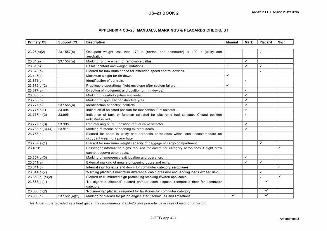
CS–23 BOOK 2
2–FTG App 4–1
APPENDIX 4 CS–23 MANUALS, MARKINGS & PLACARDS CHECKLIST
Primary CS Support CS Description Manual Mark Placard Sign
23.25(a)(2) 23.1557(b) Occupant weight less than 170 lb (normal and commuter) or 190 lb (utility and aerobatic).
ü
23.31(a) 23.1557(a) Marking for placement of removable ballast. ü 23.31(b) Ballast content and weight limitations. ü ü ü 23.373(a) Placard for maximum speed for extended speed control devices. ü 23.415(c) Maximum weight for tiedown. ü 23.671(b) Identification of controls. ü 23.672(c)(2) Practicable operational flight envelope after system failure. ü 23.677(a) Direction of movement and position of trim device. ü 23.685(d) Marking of control system elements. ü 23.733(b) Marking of specially constructed tyres. ü 23.777(a) 23.1555(a) Identification of cockpit controls. ü 23.777(h)1) 23.995 Indication of selected position for mechanical fuel selector. ü 23.777(h)(2) 23.995 Indication of tank or function selected for electronic fuel selector. Closed position
indicated in red. ü
23.777(h)(3) 23.995 Red marking of OFF position of fuel valve selector. ü 23.783(c)(3)(4) 23.811 Marking of means of opening external doors. ü 23.785(h) Placard for seats in utility and aerobatic aeroplanes which won't accommodate an
occupant wearing a parachute. ü
23.787(a)(1) Placard for maximum weight capacity of baggage or cargo compartment. ü 23.X791 Passenger information signs required for commuter category aeroplanes if flight crew
cannot observe other seats. ü
23.807(b)(3) Marking of emergency exit location and operation. ü 23.811(a) External marking of means of opening doors and exits. ü ü 23.811(b) Internal sign for exits and doors for commuter category aeroplanes. ü 23.841(b)(7) Warning placard if maximum differential cabin pressure and landing loads exceed limit. ü 23.853(c),(c)(2) Placard or illuminated sign prohibiting smoking if/when applicable. ü ü 23.853(d)(1) ‘No cigarette disposal’ placard on/near each disposal receptacle door for commuter
category. ü
23.853(d)(2) ‘No smoking’ placards required for lavatories for commuter category. ü 23.903(d) 23.1581(a)(2) Marking or placard for piston engine start techniques and limitations. ü ü
This Appendix is provided as a brief guide; the requirements in CS–23 take precedence in case of error or omission.
Annex to ED Decision 2012/012/R
Amendment 3
Annex to ED Decision 2012/012/R
Amendment 3

CS–23 BOOK 2
2–FTG App 4–2
Primary CS Support CS Description Manual Mark Placard Sign
23.903(e)(1) 23.1581(a)(2) Marking or placard for turbine engine start techniques and limitations. ü ü 23.903(e)(3) 23.1581(a)(4) Marking or placard for turbine engine inflight restart techniques and limitations. ü ü 23.905(f) Marking such that pusher propeller disk is conspicuous. ü 23.909(e) 23.1581(a)(2) Turbocharger operating procedures and limitations. ü 23.955(d)(2) 23.1555(c)(3) Placard for operating instructions for use of auxiliary fuel tank. ü 23.973(a) 23.1557(c) Marking of fuel tank filler. ü 23.1001(g) Placard for fuel jettisoning means if prohibited in some aerodynamic configurations. ü 23.1013(c) 23.1557(c) Marking oil filler tank connections. ü 23.1045(a) 23.1041 Compliance with 23.1041 must be shown for all flight phases with the procedures
established in AFM (turbines). ü
23.1047 23.1041 Compliance with 23.1041 must be shown for the climb/descent with the procedures established in AFM (pistons).
ü
23.1061(c) Marking coolant tank filler connections. ü 23.1141(a) 23.1555(a) Marking of powerplant controls. ü 23.1301(b) Labelling of equipment as to its identification, function and/or operating limitations. ü 23.1311(a)(7) Instrument markings on electronic displays. ü 23.1325(b)(3) 23.1541(a)(2) Provision of alternate static correction card, if required. ü 23.1327(b) 23.1547(e) Placard for magnetic indicator deviations of more than 10°. ü 23.1329(d) Marking of direction of motion of autopilot controls. ü 23.1337(b) Marking of appropriate units on fuel quantity indicator. ü 23.1357(d) Marking of essential circuit breakers and fuses. ü 23.1367(d) Marking of switches as to operation and circuit controlled. ü 23.1419(a) 23.1585(a) Recommended procedures for use of ice protection equipment. ü 23.1450(c) Placard for oxygen flow, duration and warning of hot generator element. ü 23.1501 23.1541
23.1589 Operating limitations and other information necessary for safe operation should be established and furnished to the crew.
ü
23.1541(a)(1) 23.1545 23.1567
Markings and placards specified by 23.154523.1567. ü ü
23.1541(a)(2) Additional information, markings and placards required for safe operation. ü ü ü
This Appendix is provided as a brief guide; the requirements in CS–23 take precedence in case of error or omission.
Annex to ED Decision 2012/012/R
Amendment 3
Annex to ED Decision 2012/012/R
Amendment 3

CS–23 BOOK 2
2–FTG App 4–3
Primary CS Support CS Description Manual Mark Placard Sign
23.1541(b) Specifies characteristics of markings and placards. ü ü 23.1541(c)(1) Select one category for basis for markings and placards for multicategory aeroplanes. ü ü ü 23.1541(c)(2) Placards and marking information for all certified categories must be furnished in the
AFM. ü ü ü
23.1543 Alignment and visibility of instrument markings. ü 23.1545(a) Marking of speeds on ASI. ü 23.1545(b) Marking of VNE, caution range, flap operating range, OEI enroute climb/descent speed
for pistons less than 2 730 kg (6 000 lb), VMC for pistons less than 2 730 kg (6 000 lb). ü
23.1545(c) Indication of variation of VNE or VNO with altitude. ü 23.1545(d) Indication of variation of VMO/MMO with altitude or lowest value. ü 23.1547(a) Marking of conditions for, and calibration of, magnetic direction indicator. ü ü 23.1549(a) Marking of powerplant instruments red radial line for maximum and minimum operating
limits. ü
23.1549(b) Marking of powerplant instruments green arc for normal range. ü 23.1549(c) Marking of powerplant instruments yellow arc for caution and takeoff range. ü 23.1549(c) Marking of powerplant instruments red arc for restricted vibration range. ü 23.1551 Marking of oil quantity indicator. ü 23.1553 23.1337(b)(1) Red radial marking at specified zero reading. ü 23.1555(a) Marking of cockpit control as to function and method of operation. ü 23.1555(b) Marking of secondary controls. ü 23.1555(c)(1) Marking of powerplant fuel controls fuel selector position. ü 23.1555(c)(2) Marking of powerplant fuel controls fuel tank sequence. ü 23.1555(c)(3) 23.955(d)(2) Placard stating conditions under which maximum usable fuel may be used from
restricted usage tank. ü
23.1555(c)(4) Marking of powerplant fuel controls multiengine fuel selector position. ü 23.1555(d)(1) Marking of usable fuel at indicator, if applicable. ü 23.1555(d)(2) Marking of usable fuel at selector, if applicable. ü 23.1555(e)(1) Marking of landing gear position indicator. ü 23.1555(e)(2) Marking of emergency controls red and of method of operation. ü 23.1557(a) Placard for baggage, cargo and ballast for weight and content. ü
This Appendix is provided as a brief guide; the requirements in CS–23 take precedence in case of error or omission.
Annex to ED Decision 2012/012/R
Amendment 3
Annex to ED Decision 2012/012/R
Amendment 3

CS–23 BOOK 2
2–FTG App 4–4
Primary CS Support CS Description Manual Mark Placard Sign
23.1557(b) 23.25(c)(2) Placard for seats not capable of carrying more than 170 lb. ü 23.1557(c)(1)(i) 23.973(a) Marking of fuel filler openings (piston). ü 23.1557(c)(1)(ii) 23.973(a) Marking of fuel filler openings (turbine) and AFM requirement. ü ü 23.1557(c)(2) Marking of oil filler openings and AFM requirement. ü ü 23.1557(c)(3) Marking of coolant filler openings. ü 23.1557(d) Placard for emergency exits and controls. ü 23.1557(e) Marking of system voltage of each DC installation. ü 23.1559(a)(1) Placard stating that aeroplane must be operated in accordance with AFM. ü 23.1559(a)(2) Placard stating the certificated category to which placards apply. ü 23.1559(b) For multicategory aeroplanes, a placard stating that other limitations are contained in
the AFM. ü
23.1559(c) 23.1525 Placard specifying the kinds of operation. ü 23.1561(a) Marking of safety equipment as to method of operation. ü 23.1561(b) Marking of stowage provisions for safety equipment. ü 23.1563(a) Placard of VA close to ASI. ü 23.1563(b) Placard of VLO close to ASI. ü 23.1563(c) Placard of VMC close to ASI for pistons greater than 2 730 kg (6 000 lb) and turbines. ü 23.1567(a) Placard prohibiting aerobatic manoeuvres, including spins, for normal category
aeroplanes. ü
23.1567(b)(1) Placard listing approved aerobatic manoeuvres for utility category aeroplanes. ü 23.1567(b)(2) Placard stating ‘spins prohibited’ for utility category aeroplanes that do not meet the
aerobatic spin requirements. ü
23.1567(c) Placard listing approved aerobatic manoeuvres and recommended entry airspeed; also stating if inverted manoeuvres are not allowed.
ü
23.1567(d) Placard listing conditions and control actions for recovery from a spin. ü 23.1581(a) 23.1583
23.1589 Requires AFM be submitted to the Agency. AFM must contain information required by 23.1583 23.1589, other information necessary for safe operation and information necessary to comply with the operating rules.
ü
23.1581(b)(1) 23.1583 23.1589
Information required by 23.1583 23.1589 must be approved and segregated from unapproved information.
ü
This Appendix is provided as a brief guide; the requirements in CS–23 take precedence in case of error or omission.
Annex to ED Decision 2012/012/R
Amendment 3
Annex to ED Decision 2012/012/R
Amendment 3

CS–23 BOOK 2
2–FTG App 4–5
Primary CS Support CS Description Manual Mark Placard Sign
23.1581(b)(2)(i) 23.1583 Operating limitations must be approved and clearly distinguished from other parts of the AFM (does not apply to pistons less than or equal to 2 730 kg (6 000 lb)).
ü
23.1581(b)(2)(ii) 23.1585 23.1589
Procedures, performance and loading information must be presented in a manner acceptable to the Agency (does not apply to pistons less than or equal to 2 730 kg (6 000 lb)).
ü
23.1581(c) Units in the AFM must be the same as those marked on the appropriate instruments and placards.
ü ü
23.1581(d) All AFM operational airspeeds must, unless otherwise specified, be presented as indicated airspeeds.
ü
23.1581(e) Provisions must be made for stowing the AFM in a suitable fixed container readily accessible to the pilot.
ü
23.1581(f) Each AFM must contain a means for recording the incorporation of revisions and/or amendments. ü 23.1583 Each AFM must contain operating limitations, including the following: ü ü 23.1583(a)(1) 23.1545 Information necessary for the marking of airspeed limits as required in 23.1545. ü ü 23.1583(a)(2) The speeds VMC, VA, VLE and VLO and their significance. ü 23.1583(a)(3)(i) VMO/MMO and a statement that this speed must not be deliberately exceeded without
authorisation (for turbine powered commuters). ü
23.1583(a)(3)(ii) If an airspeed limitation is based on compressibility effects, a statement to this effect, further information and the recommended recovery procedure (for turbine powered commuters).
ü
23.1583(a)(3)(iii) The airspeed limits must be shown in terms of VMO/MMO for (turbine powered commuters). ü 23.1583(b)(1),(2) 23.1521 Powerplant limitations required by 23.1521 and explanations, when appropriate. ü 23.1583(b)(3) 23.1549
23.1553 Information necessary for marking powerplant instruments required in 23.1549 to 23.1553. ü
23.1583(c)(1) Maximum weight. ü 23.1583(c)(2) Maximum landing weight (if less than maximum weight). ü 23.1583(c)(3) 23.63(c)1) MTOW for each aerodrome altitude and temperature selected by the applicant at which the
aeroplane complies with 23.63(c)(1) (not for pistons less than 2 730 kg (6 000 lb) and commuters).
ü
23.1583(c)(4) 23.63(d)(1), 23.55, 23.59(a), 23.59(b)
For commuter aeroplanes, the MTOW for each aerodrome altitude and temperature selected by the applicant at which the aeroplane complies with the climb requirements of 23.63(d)(1), the acceleratestop distance determined in 23.55 is acceptable, the takeoff distance determined in 23.59(a) is acceptable and, optionally, the takeoff run determined in 23.59(b) is acceptable.
ü
23.1583(c)(5) 23.63(d)(2), 23.75, 23.343
For commuter aeroplanes, the maximum landing weight for each aerodrome altitude selected by the applicant at which the aeroplane complies with the climb requirements of 23.63(d)(2), the landing distance determined in 23.75 is acceptable and the maximum zero wing fuel weight established in 23.343.
ü
23.1583(d) The established centre of gravity limits. ü
Annex to ED Decision 2012/012/R
Amendment 3
Annex to ED Decision 2012/012/R
Amendment 3

CS–23 BOOK 2
2–FTG App 4–6
This Appendix is provided as a brief guide; the requirements in CS–23 take precedence in case of error or omission. Primary CS Support CS Description Manual Mark Placard Sign
23.1583(e) 23.221(c) Authorised manoeuvres, appropriate airspeed limitations, recommended entry speeds, spin recovery procedures and unauthorised manoeuvres according to category.
ü
23.1583(f) Positive limit load factors and, for aerobatic aeroplanes, the negative limit load factors. ü 23.1583(g) 23.1523 Number and functions of the minimum flight crew. ü 23.1583(h) 23.1525 Lists of kinds of operation according to 23.1525, installed equipment affecting any
operating limitation and identification as to equipment's required operational status. ü
23.1583(i) 23.1527 Maximum operating altitude. ü 23.1583(j) Maximum passenger seating configuration. ü 23.1583(k) Maximum allowable lateral fuel loading differential, if less than the maximum possible. ü 23.1583(l) Maximum allowable load and maximum intensity of loading for baggage and cargo
compartments or zones. ü
23.1583(m) Any limitations on the use of aeroplane systems and equipment. ü 23.1583(n) Where appropriate, maximum and minimum ambient temperatures for operation. ü 23.1583(o) Any restrictions on smoking in the aeroplane. ü 23.1583(p) 23.45(g),
23.1587(a)(5) Types of surface on which operation may be conducted (see 23.45(g) and 23.1587(a)(5)).
ü
23.1585(a) Information concerning normal, abnormal and emergency procedures and other information necessary for safe operation and achievement of scheduled performance; including.
ü
23.1585(a)(1) Explanation of significant or unusual flight or ground handling characteristics. ü 23.1585(a)(2) Maximum demonstrated values of crosswind for takeoff and landing and associated
procedures. ü
23.1585(a)(3) A recommended speed for flight in rough air. ü 23.1585(a)(4) 23.903(f) Procedures for restarting any engine in flight, including the effects of altitude. ü 23.1585(a)(5) 23.73, 23.75 Procedures, speeds and configurations for making a normal approach and landing in
accordance with 23.73 and 23.75 and a transition to the balked landing condition. ü
23.1585(b) 23.71 For all singleengined aeroplanes, procedures, speeds and configurations for a glide following engine failure and the subsequent forced landing.
ü
23.1585(c)(1) For all twinengined aeroplanes, procedures, speeds and configurations for making an approach and landing with one engine inoperative.
ü
23.1585(c)(2) For all twinengined aeroplanes, procedures, speeds and configurations for making a goaround with one engine inoperative, the conditions under which it can be performed safely or a warning against attempting a goaround.
ü
This Appendix is provided as a brief guide; the requirements in CS–23 take precedence in case of error or omission.
Annex to ED Decision 2012/012/R
Amendment 3
Annex to ED Decision 2012/012/R
Amendment 3

CS–23 BOOK 2
2–FTG App 4–7
Primary CS Support CS Description Manual Mark Placard Sign
23.1585(d)(1) 23.51(a),(b), 23.53(a),(b), 23.65, 23.69(a)
For all normal, utility and aerobatic aeroplanes, procedures, speeds and configurations for making a normal takeoff (23.51(a),(b) 23.53(a),(b)) and the subsequent climb (23.65, 23.69(a)).
ü
23.1585(d)(2) For all normal, utility and aerobatic aeroplanes, procedures for abandoning a takeoff. ü 23.1585(e)(1) For all normal, utility and aerobatic twinengined aeroplanes, procedures and speeds for
continuing a takeoff following engine failure, the conditions under which it can be performed safely or a warning against continuing the takeoff.
ü
23.1585(e)(2) 23.67, 23.69(b) For all normal, utility and aerobatic twinengined aeroplanes, procedures and speeds for continuing a climb following engine failure after takeoff (23.67) or enroute (23.69(b)).
ü
23.1585(f)(1) For commuter category aeroplanes, procedures, speeds and configurations for making a normal takeoff.
ü
23.1585(f)(2) 23.55 For commuter category aeroplanes, procedures and speeds for carrying out an acceleratestop
ü
23.1585(f)(3) 23.57, 23.59(a)(1), 23.61(a)
For commuter category aeroplanes, procedures and speeds for continuing a takeoff following engine failure (23.59(a)(1)) and for following the flight path (23.57, 23.61(a)).
ü
23.1585(g) 23.953 For twinengined aeroplanes, information and instructions regarding fuel supply independence.
ü
23.1585(h) 23.1353(g)(2)2 3.1353(g)(3)
For each aeroplane showing compliance with 23.1353(g)(2) or (g)(3), the procedures for disconnecting the battery from its charging source.
ü
23.1585(i) Information on the total quantity of usable fuel for each tank and the effect pump failure. ü 23.1585(j) Procedures for the safe operation of the aeroplane's systems and equipment, in normal
use and in the event of malfunction. ü
23.1587 23.45(b) Unless otherwise presented, performance information must be provided over the altitude and temperature ranges required by 23.45(b).
ü
23.1587(a)(1) 23.49 Stalling speeds VS0 and VS1 at maximum weight with landing gear and wing flaps retracted and the effect on these stalling speeds of bank angles up to 60°.
ü
23.1587(a)(2) 23.69(a) Steady rate and gradient of climb with all engines operating. ü 23.1587(a)(3) 23.75 The landing distance for each aerodrome altitude and standard temperature and the
type of surface for which it is valid. ü
23.1587(a)(4) 23.45(g) The effect on landing distance of operation on other than smooth hard surfaces, when dry.
ü
23.1587(a)(5) The effect on landing distance of runway slope, 50% of the headwind component and 150% of the tailwind component.
ü
This Appendix is provided as a brief guide; the requirements in CS–23 take precedence in case of error or omission.
Annex to ED Decision 2012/012/R
Amendment 3
Annex to ED Decision 2012/012/R
Amendment 3

CS–23 BOOK 2
2–FTG App 4–8
Primary CS Support CS Description Manual Mark Placard Sign
23.1587(b) 23.77(a) For normal, utility and aerobatic piston aeroplanes of 2 730 kg (6 000 lb) or less, the steady angle of climb/descent.
ü
23.1587(c)(1) 23.53 For normal, utility and aerobatic aeroplanes, the takeoff distance and the type of surface for which it is valid.
ü
23.1587(c)(2) 23.45(g) The effect on takeoff distance of operation on other than smooth hard surfaces, when dry. ü 23.1587(c)(3) The effect on takeoff distance of runway slope, 50% of the headwind component and
150% of the tailwind component. ü
23.1587(c)(4) 23.66 For twin piston aeroplanes of more than 2 730 kg (6 000 lb) MTOW and turbine aeroplanes, the oneengineinoperative takeoff climb/descent gradient.
ü
23.1587(c)(5) 23.69(b) For twinengined aeroplanes, the enroute rate and gradient of climb/descent with one engine inoperative.
ü
23.1587(c)(6) 23.71 For singleengined aeroplanes, the glide performance. ü 23.1587(d)(1) 23.55 For commuter aeroplanes, the acceleratestop distance. ü 23.1587(d)(2) 23.59(a) For commuter aeroplanes, the takeoff distance. ü 23.1587(d)(3) 23.59(b) For commuter aeroplanes, the takeoff run at the applicant's option. ü 23.1587(d)(4) 23.45(g) For commuter aeroplanes, the effect on acceleratestop distance, takeoff distance and,
if determined, takeoff run of operation on other than smooth hard surfaces, when dry. ü
23.1587(d)(5) For commuter aeroplanes, the effect on acceleratestop distance, takeoff distance and, if determined, takeoff run of runway slope, 50% of the headwind component and 150% of the tailwind component.
ü
23.1587(d)(6) 23.61(b) For commuter aeroplanes, the net takeoff path. ü 23.1587(d)(7) 23.69(b) For commuter aeroplanes, the enroute gradient of climb/descent with one engine
inoperative. ü
23.1587(d)(8) For commuter aeroplanes, the effect on the net takeoff path and the enroute gradient of climb/descent with one engine inoperative, of 50% of the headwind component and 150% of the tailwind component.
ü
23.1587(d)(9) 23.63(d)(2), 75 For commuter aeroplanes, overweight landing performance information (the maximum weight at which the aeroplane complies with 23.63(d)(2) and the landing distance determined in 23.75).
ü
23.1587(d)(10) 23.1323(b),(c) For commuter aeroplanes, the relationship between IAS and CAS. ü 23.1587(d)(11) 23.1325(e) For commuter aeroplanes, the altimeter system calibration. ü 23.1587(d)(7) 23.69(b) For commuter aeroplanes, the enroute gradient of climb/descent with one engine
inoperative. ü
23.1589(a) 23.25 The weight and location of each item of equipment that can be easily removed and was installed when the aeroplane was weighed.
ü
23.1589(b) 23.23, 23.25 Appropriate loading instructions for each permissible loading condition of weight and cg. ü App. G232,3,4 23.1529 Instructions for continued airworthiness. ü
This Appendix is provided as a brief guide; the requirements in CS–23 take precedence in case of error or omission.
Annex to ED Decision 2012/012/R
Amendment 3
Annex to ED Decision 2012/012/R
Amendment 3

CS–23 BOOK 2
2–FTG App 5–1
APPENDIX 5 (RESERVED)
Annex to ED Decision 2012/012/R
Amendment 3
Annex to ED Decision 2012/012/R
Amendment 3

Annex to ED Decision 2012/012/R
Amendment 3
Annex to ED Decision 2012/012/R
Amendment 3

Annex to ED Decision 2012/012/R
Amendment 3
Annex to ED Decision 2012/012/R
Amendment 3

CS–23 BOOK 2
2–FTG App 6–1
APPENDIX 6 SAMPLE KINDS OF OPERATING EQUIPMENT LIST
This aeroplane may be operated in day or night VFR, day or night IFR, and known or forecast icing conditions when the appropriate equipment is installed and operable.
The following equipment list identifies the systems and equipment upon which type certification for each kind of operation was predicated. The following systems and items of equipment must be installed and operable for the particular kind of operation indicated.
The ATA numbers refer to equipment classifications of Air Transport Association Specification Code 100.
VFR Day
VFR Night
IFR Day
IFR Night
Icing Conditions
Communications (ATA23)
1. Communication Radio (VHF) 0 0 1 1 1
Electrical Power (ATA24)
1. Battery 1 1 1 1 1 2. D.C. Generator 2 2 2 2 2 3. D.C. Loadmeter 2 2 2 2 2 4. D.C. Generator Warning Light 2 2 2 2 2 5. Inverter 2 2 2 2 2 6. Inverter Warning Light 1 1 1 1 1 7. Feeder Limiter Warning Light 1 1 1 1 1 8. Battery Monitor system 1 1 1 1 1 9. AC Volt Meter 1 1 1 1 1
Equipment/Furnishings (ATA25)
1. Exit Signs – SelfIlluminated 4 4 4 4 4
Fire Protection (ATA26)
1. Engine Fire Detector System 2 2 2 2 2 2. Firewall Fuel Shutoff System 2 2 2 2 2
Annex to ED Decision 2012/012/R
Amendment 3
Annex to ED Decision 2012/012/R
Amendment 3

CS–23 BOOK 2
2–FTG App 6–2
VFR Day
VFR Night
IFR Day
IFR Night
Icing Conditions
Flight Controls (ATA27)
1. Flap System 1 1 1 1 1 2. Flap Position Indicator 1 1 1 1 1 3. Horizontal Stabiliser Trim System – Main 1 1 1 1 1 4. Horizontal Stabiliser Trim System – Standby 1 1 1 1 1 5. Stabiliser outoftrim Aural Warning Indicator 1 1 1 1 1 6. TriminMotion Aural Indicator 1 1 1 1 1 7. Horizontal Stabiliser Position Indicator 1 1 1 1 1 8. Stall Warning Horn 1 1 1 1 1 9. Trim Tab Indicator – Rudder 1 1 1 1 1 10.Trim Tab Indicator Aileron 1 1 1 1 1
Fuel (ATA28)
1. Fuel Boost Pumps (4 are installed) PER AFM Limitations 2. Fuel Quantity Indicator 2 2 2 2 2 3. Fuel Quantity Gauge Selector Switch 1 1 1 1 1 4. Nacelle NotFull Warning Light 2 2 2 2 2 5. Crossfeed Light 1 1 1 1 1 6. Fuel Boost Pump Low Pressure Warning Light 2 2 2 2 2 7. Fuel Flow Indicator 2 2 2 2 2 8. Jet Transfer Pump 2 2 2 2 2
Ice and Rain Protection (ATA30)
1. Engine Inlet Scoop Deicer Boot 2 2 2 2 2 2. Indicator – Propeller/Inlet Deicer 1 1 1 1 1 3. Engine Inertial AntiIcing System 2 2 2 2 2 4. Pitot Heat 0 0 2 2 2 5. Alternate Static Air Source 0 0 1 1 1 6. Engine AutoIgnition system (if installed) 2 2 2 2 2 7. Propeller Deicer System 0 0 0 0 1 8. Windshield Heat (Left) 0 0 0 0 1 9. Surface Deicer System 0 0 0 0 1 10.Stall Warning Mounting Plate Heater 0 0 0 0 1 11.Wing Ice Light (Left) 0 0 0 0 1 12. Windshield Wiper (Left) 1 1 1 1 1
Instruments (ATA31)
1. Clock 0 0 1 1 1
Annex to ED Decision 2012/012/R
Amendment 3
Annex to ED Decision 2012/012/R
Amendment 3

CS–23 BOOK 2
2–FTG App 6–3
VFR Day
VFR Night
IFR Day
IFR Night
Icing Conditions
Landing Gear (ATA32)
1. Landing Gear Position Indicator Lights 3 3 3 3 3 2. FlapControlled Landing Gear Aural Warning 1 1 1 1 1 3. Nose Steering Disconnect Actuator 1 1 1 1 1 4. Landing Gear Hydraulic Pump 1 1 1 1 1
Lights (ATA33)
1. Cockpit and Instrument (Required Illumination) 0 1 0 1 0 2. AntiCollision 0 2 0 2 0 3. Landing Light 0 2 0 2 0 4. Position Lights 0 3 0 3 0 5. Cabin Door Warning Light (Note) 1 1 1 1 1 6. Baggage Door Warning Light (Note)
Note: Where combined into one cabin/baggage annunciator – one (1) is required for all conditions.
Navigation (ATA34)
1. Altimeter 1 1 1 1 1 2. Airspeed 1 1 1 1 1 3. Magnetic Compass 1 1 1 1 1 4. Outside Air Temperature 1 1 1 1 1 5. Attitude Indicator (Gyro stabilised) 0 0 1 1 1 6. Directional Indicator (Gyro stabilised) 0 0 1 1 1 7. Sensitive Altimeter 0 0 1 1 1 8. Turn and Bank Indicator or Turn Coordinator 0 0 1 1 1 9. Vertical Speed Indicator 0 0 1 1 1 10.Navigation Radio (VHF) 0 0 1 1 1
Vacuum System
1. Suction or Pressure Gauge 1 1 1 1 1 2. Instrument Air System 1 1 1 1 1
Propeller (ATA61)
1. Autofeather System 2 2 2 2 2 2. Low Pitch Light 2 2 2 2 2 3. Do Not Reverse Warning Light 1 1 1 1 1 4. Propeller Reversing 2 2 2 2 2
Annex to ED Decision 2012/012/R
Amendment 3
Annex to ED Decision 2012/012/R
Amendment 3

CS–23 BOOK 2
2–FTG App 6–4
VFR Day
VFR Night
IFR Day
IFR Night
Icing Conditions
Engine Indicating (ATA77)
1. Tachometer Indicator (Propeller) 2 2 2 2 2 2. Tachometer Indicator (Gas Generator) 2 2 2 2 2 3. ITT Indicator 2 2 2 2 2 4. Torque Indicator 2 2 2 2 2
Engine Oil (ATA79)
1. Oil Temperature Indicator 2 2 2 2 2 2. Oil Pressure Indicator 2 2 2 2 2 3. Low Oil Pressure Light 2 2 2 2 2 4. Engine Chip Detector System 2 2 2 2 2
Note 1: The zeros (0) used in the above list mean that the equipment and/or system was not required for type certification for that kind of operation.
Note 2: The above system and equipment list is predicated on a crew of one pilot.
Note 3: Equipment and/or systems in addition to those listed above may be required by the operating regulations.
Note 4: Further information may be drawn from an approved Minimum Equipment List (MEL), if applicable.
Annex to ED Decision 2012/012/R
Amendment 3
Annex to ED Decision 2012/012/R
Amendment 3

CS–23 BOOK 2
2–FTG App 7–1
APPENDIX 7 USEFUL INFORMATION
STANDARD ATMOSPHERE
Geopotential Altitude
Temp∙ Temp∙ Ratio Press∙ Press∙ Ratio Density Density Ratio Speed of Sound
h T θ p δ ρ σ Va
ft °F °R °C psi slug/ft 3 ft/sec
0 59∙0 518∙7 15∙0 1∙000 14∙70 1∙000 2∙3768x10 –3 1∙000 1 116∙4 1 000 55∙4 515∙1 13∙0 ∙9932 14∙17 ∙9644 2∙3081 ∙97106 1 112∙6 2 000 51∙9 511∙5 11∙0 ∙9863 13∙66 ∙9298 2∙2409 ∙94277 1 108∙7 3 000 48∙3 508∙0 9∙1 ∙9794 13∙17 ∙8962 2∙1751 ∙91512 1 104∙9 4 000 44∙7 504∙4 7∙1 ∙9725 12∙69 ∙8637 2∙1109 ∙88809 1 101∙0 5 000 41∙2 500∙8 5∙1 ∙9657 12∙23 ∙8320 2∙0481 ∙86167 1 097∙1
6 000 37∙6 497∙3 3∙1 ∙9588 11∙78 ∙8014 1∙9868 ∙83586 1 093∙2 7 000 34∙0 493∙7 1∙1 ∙9519 11∙34 ∙7716 1∙9268 ∙81064 1 089∙2 8 000 30∙5 490∙1 –0∙9 ∙9450 10∙92 ∙7428 1∙8683 ∙78602 1 085∙3 9 000 26∙9 486∙6 –2∙8 ∙9382 10∙50 ∙7148 1∙8111 ∙76196 1 081∙4 10 000 23∙3 483∙0 –4∙8 ∙9313 10∙11 ∙6877 1∙7553 ∙73848 1 077∙4
11 000 19∙8 479∙4 –6∙8 ∙9244 9∙720 ∙6614 1∙7008 ∙71555 1 073∙4 12 000 16∙2 475∙9 –8∙8 ∙9175 9∙346 ∙6360 1∙6476 ∙69317 1 069∙4 13 000 12∙6 472∙3 –10∙8 ∙9107 8∙984 ∙6113 1∙5957 ∙67133 1 065∙4 14 000 9∙1 468∙7 –12∙7 ∙9038 8∙633 ∙5875 1∙5451 ∙65003 1 061∙4 15 000 5∙5 465∙2 –14∙7 ∙8969 8∙294 ∙5643 1∙4956 ∙62924 1 057∙3
16 000 1∙9 461∙6 –16∙7 ∙8900 7∙965 ∙5420 1∙4474 ∙60896 1 053∙2 17 000 –1∙6 458∙0 –18∙7 ∙8831 7∙647 ∙5203 1∙4004 ∙58919 1 049∙2 18 000 –5∙2 454∙5 –20∙7 ∙8763 7∙339 ∙4994 1∙3546 ∙56991 1 045∙1 19 000 –8∙8 450∙9 –22∙6 ∙8694 7∙041 ∙4791 1∙3100 ∙55112 1 041∙0 20 000 –12∙3 447∙3 –24∙6 ∙8625 6∙754 ∙4595 1∙2664 ∙53281 1 036∙8
21 000 –15∙9 443∙8 –26∙6 ∙8556 6∙475 ∙4406 1∙2240 ∙51497 1 032∙7 22 000 –19∙5 440∙2 –28∙6 ∙8488 6∙207 ∙4223 1∙1827 ∙49758 1 028∙5 23 000 –23∙0 436∙6 –30∙6 ∙8419 5∙947 ∙4046 1∙1425 ∙48065 1 024∙4 24 000 –26∙6 433∙1 –32∙5 ∙8350 5∙696 ∙3876 1∙1033 ∙46417 1 020∙2 25 000 –30∙2 429∙5 –34∙5 ∙8281 5∙454 ∙3711 1∙0651 ∙44812 1 016∙0
Annex to ED Decision 2012/012/R
Amendment 3
Annex to ED Decision 2012/012/R
Amendment 3

CS–23 BOOK 2
2–FTG App 7–2
STANDARD ATMOSPHERE
Geopotential Altitude
Temp∙ Temp∙ Ratio Press∙ Press∙ Ratio Density Density Ratio Speed of Sound
h T θ p δ ρ σ Va
ft °F °R °C psi Slug/ft 3 ft/sec
26000 –33∙7 426∙0 –36∙6 ∙8213 5∙220 ∙3552 1∙0280 ∙43250 1 011∙7 27000 –37∙3 422∙4 –38∙5 ∙8144 4∙994 ∙3398 ∙9919 ∙41730 1 007∙5 28000 –40∙9 418∙8 –40∙5 ∙8075 4∙777 ∙3250 ∙9567 ∙40251 1 003∙2 29000 –44∙4 415∙3 –42∙5 ∙8006 4∙567 ∙3107 ∙9225 ∙38812 999∙0 30000 –48∙0 411∙7 –44∙4 ∙7938 4∙364 ∙2970 ∙8893 ∙37413 994∙7
31000 –51∙6 408∙1 –46∙4 ∙7869 4∙169 ∙2837 ∙8569 ∙36053 990∙3 32000 –55∙1 404∙6 –48∙4 ∙7800 3∙981 ∙2709 ∙8255 ∙34731 986∙0 33000 –58∙7 401∙0 –50∙4 ∙7731 3∙800 ∙2586 ∙7950 ∙33447 981∙6 34000 –62∙2 397∙4 –52∙4 ∙7663 3∙626 ∙2467 ∙7653 ∙32199 977∙3 35000 –65∙8 393∙9 –54∙3 ∙7594 3∙458 ∙2353 ∙7365 ∙30987 972∙9
36000 –69∙4 390∙3 –56∙4 ∙7525 3∙297 ∙2243 ∙7086 ∙29811 968∙5 37000 –69∙7 390∙0 –56∙5 ∙7519 3∙142 ∙2138 ∙6759 ∙28435 968∙1 38000 –69∙7 390∙0 –56∙5 ∙7519 2∙994 ∙2038 ∙6442 ∙27101 968∙1 39000 –69∙7 390∙0 –56∙5 ∙7519 2∙854 ∙1942 ∙6139 ∙25829 968∙1
40000 –69∙7 390∙0 –56∙5 ∙7519 2∙720 ∙1851 ∙5851 ∙24617 968∙1 41000 –69∙7 390∙0 –56∙5 ∙7519 2∙592 ∙1764 ∙5577 ∙23462 968∙1 42000 –69∙7 390∙0 –56∙5 ∙7519 2∙471 ∙1681 ∙5315 ∙22361 968∙1 43000 –69∙7 390∙0 –56∙5 ∙7519 2∙355 ∙1602 ∙5065 ∙21311 968∙1 44000 –69∙7 390∙0 –56∙5 ∙7519 2∙244 ∙1527 ∙4828 ∙20311 968∙1
45000 –69∙7 390∙0 –56∙5 ∙7519 2∙139 ∙1455 ∙4601 ∙19358 968∙1 46000 –69∙7 390∙0 –56∙5 ∙7519 2∙039 ∙1387 ∙4385 ∙18450 968∙1 47000 –69∙7 390∙0 –56∙5 ∙7519 1∙943 ∙1322 ∙4180 ∙17584 968∙1 48000 –69∙7 390∙0 –56∙5 ∙7519 1∙852 ∙1260 ∙3983 ∙16759 968∙1 49000 –69∙7 390∙0 –56∙5 ∙7519 1∙765 ∙1201 ∙3796 ∙15972 968∙1
50000 –69∙7 390∙0 –56∙5 ∙7519 1∙682 ∙1145 ∙3618 ∙15223 968∙1
°Rankine = °F + 459∙7° °Kelvin = °C + 273∙2°
Annex to ED Decision 2012/012/R
Amendment 3
Annex to ED Decision 2012/012/R
Amendment 3

CS–23 BOOK 2
2–FTG–App 7–3
Figure 2 – TEMPERATURE CONVERSION CHART
90
100
110
120
130
140
150
160
170
180
190
200
210
220
230
240
250
30
40
50
60
70
80
90
100
110
120
F o C
60 80
70
60
50
40
30
20
10
0 F
80
10
20
30
40
50
60
70
50
40
30
20
10
0
10
20
o C
o o
Annex to ED Decision 2012/012/R
Amendment 3
Annex to ED Decision 2012/012/R
Amendment 3

CS–23 BOOK 2
2–FTG–7–4
Figure 3
40 20 60 0 20 40 60 80 100 120
SL
2
4
6
8
10
12
14
16
18
20
22
24
26
Altitude 1000 Feet
Air temperature F O
ISA+60
F
ISA+50
F
ISA+ 40
F
ISA+30
F
ISA+ 20
F
ISA+ 10
F
ISA
ISA 10
F
ISA 20
F
ISA 30
F
ISA 40
F
ISA 50
F
ISA 60
F
O O
O O
O O
O O
O O
O O
Determination of air temperature in relation to international standard atmosphere
Annex to ED Decision 2012/012/R
Amendment 3
Annex to ED Decision 2012/012/R
Amendment 3

CS–23 BOOK 2
2–FTG–App 7–5
Figure 4 – DENSITY/PRESSURE ALTITUDE CONVERSION
5000
4000
3000
2000
1000
0
1000
2000
4000
5000
6000
7000
8000
9000
10000
12000
13000
14000
15000
16000
5000
4000
3000
2000
1000
0
1000
2000
3000
4000
5000
6000
7000
8000
9000
10000
11000
12000
13000
14000
15000
16000
20 10 0 10 20 30 40 50 60 70 80 100 F 90 440 450 460 470 480 490 500 510 520 530 540 560 F 550
o o ABS
30 20 10 0 10 40 30 20 o C
20 10 0 10 20 30 40 50 60 70 80 100 F 90 o
“StandardAltitude”
1.00 1.10 0.90 0.80 0.70 0.60 ρ/ρ Ο
Densityaltitudefeet
Densityaltitudefeet
1000
2000
3000
4000
5000
6000
7000
8000
9000
10000
11000
12000
13000
14000
15000
16000
17000 110
00
10000
9000
8000
7000
6000
5000
4000
3000
2000
1000
0
1000
2000
3000
4000
5000
6000
Pressu
re Altitu
de Al
timete
setting
29.92” Hg
ρ/ρ Ο
ρ/ρ Ο
Annex to ED Decision 2012/012/R
Amendment 3
Annex to ED Decision 2012/012/R
Amendment 3

CS–23 BOOK 2
2–FTG–7–6
140 160 180
V (Calibrated airspeed) ~ knots
220 240 260 280 300 320
0
1
2
3
4
5
6
7
8
9
10
11
12
2000 S.L.
6000 8000
10000
12000
14000
16000
18000
20000
22000 24
000
26000
30000
32000
34000
36000
28000
38000
40000
4000
310 300 290
280
270
260
250 240
230
220
210
180
190
200
170
160
150
c
200
V ~
knots
c
V ~
kno
ts
c 140
Compressibility correction to obtain V (Equivalent airspeed) e
V = V ~ V e c c Pressure
altitude FT.
41000
Figure 5 – COMPR
ESSIBILITY C
ORREC
TION TO
GAS
Annex to ED Decision 2012/012/R
Amendment 3
Annex to ED Decision 2012/012/R
Amendment 3

CS23 BOOK 2
2–FTG–App 7–7
Figure 6 – ALTIM
ETE
R ERROR VS. C
AS
Assumes no error in total pressure head and airspeed
position error less than 10 knots
dV dh
= 0.08865 V
o c
std [ 1+.2 ( V c
661.5
( 2 2.5 [
SEA level
5000 FT
10000 FT
15000 FT
20000 F
T 250
00 FT
30000
FT 350
00FT 40
000 FT 45000 FT
50000 FT
0 40 80 120 160 200 240 280 320 360 400 440 0
10
20
30
40
50
60
70
80
90
100
110
120
130
140
150
Calibrated airspeed ~ KT
c
dV dh c
( FT KT (
Annex to ED Decision 2012/012/R
Amendment 3
Annex to ED Decision 2012/012/R
Amendment 3

CS–23 BOOK 2
2–FTG–7–8
1.00
1.02
1.04
1.06
1.08
1.10
1.12
1.14
1.16
1.18
1.20
190 180 200 230 250 260 270 320 280
0.2 0.3 0.4 0.5 0.6 0.7 0.8 1.0 0.9
50 20 20 60 70 30 40 90 60 40 10 80 10 30 50 ( C ) 0 210 220 240 290 300 310 330 o o o o o o o o o o o o o o o o
o o o o o o o o o o o o o o o o o
Ratio indicated temp.to outside air temp.
80 o
70 o
60 o
50 o
40 o
30 o
20 o
10 o
0 o
10 o
20 o
30 o
40 o
50 o 70 o
80 o
90 o
60 o
100
50
80 o
40 o
70 o o
20 o
10 o
0 o
10 o
20
30 o
40 o o
50 o o
30
60 o
o
Mach number, M
( K ) o
Outside air temperature
K=1.00
0.95
0.90
0.85
0.80
Indicated temperature ( C) o
Indicated Temp. ( K)
Outside Air Temp. ( K) = 1 + ( recovery factor)
Mach number 2
5
o
o
Figure 7 – TEMPERATU
RE RAM RISE
Annex to ED Decision 2012/012/R
Amendment 3
Annex to ED Decision 2012/012/R
Amendment 3

CS23 BOOK 2
2–FTG–App 7–9
Figure 8
160
50 60 70 80 90 100 110 120 130 140 150 160 170 180 190 200 210 220 230 50
60
70
80
90
100
110
120
130
140
150
Stalling speed as a function of angle of bank ø
Vstall = Vstall at 0 cos Ø
Stall speed at bank angle Ø
Stalling speed as a function of angle of bank Ø
Stall speed 0 angle of bank
10 o 15 o
20 o 30 o
40 o 45 o 50 o
60 o
Ø
o
Annex to ED Decision 2012/012/R
Amendment 3
Annex to ED Decision 2012/012/R
Amendment 3

CS–23 BOOK 2
2–FTG–7–10
Figure 9
0 10 20 30 40 50 60 70 80 1.0
2.0
3.0
4.0
5.0
6.0
g = = L W
1 cos Ø
Where Ø = angle of bank
Vectorial acceleration versus angle of bank
Bank angle degrees
Vectorial acceleration g
’s
Annex to ED Decision 2012/012/R
Amendment 3
Annex to ED Decision 2012/012/R
Amendment 3

CS23 BOOK 2
2–FTG App 7–11
Figure 10
800
500
700
400
600
300
200
100
0
40 60 80 100 120 160 140
Rate of clim
b feet/min
5.0%
4.5%
4.0%
2
3.0%
2.5%
2.0%
1
1.5%
1.0%
0.5%
3 o 4 o 14% 6 o 5 o 8 o 12% 10% 9% 8.0% 7.0% 6.0% 5.5%
3.5% o
o
Angle of c
limbdeg
rees
Climbgradi
ent perce
nt
Annex to ED Decision 2012/012/R
Amendment 3
Annex to ED Decision 2012/012/R
Amendment 3

CS23 BOOK 2
2–FTG App 7–12
Figure 10 (continued)
800
700
4.0% 3.5 % 3.0%
600
500
400
300
200
100
0
160 180 200 220 240 260 280
0.5%
1.0%
1.5%
1
2.0%
2.5%
o
Flight path velocity knots (TAS)
Ateofclimb feet/m
in
Angle of c
limb deg
rees Climb gra
dient pe
rcent
2 o
Annex to ED Decision 2012/012/R
Amendment 3
Annex to ED Decision 2012/012/R
Amendment 3

CS23 BOOK 2
2–FTG App 7–13
Figure 11
Flight path runway centerline
60
50
40
30
20
10
0
10
20
180 o 160
150 140 130
Crosswind component ~ knots
0 10 20 30 40 50 60
110
100
o o o o o o
o
o 90
o 80
o 70
o 60
o 50
o 40
o 30
o 20
o 10 o 0
Takeoff and landing crosswind component
50
40 30
20
10 Wind angle, degrees
Wind velocity,
60 knot
Head component ~ knots
120
Annex to ED Decision 2012/012/R
Amendment 3
Annex to ED Decision 2012/012/R
Amendment 3

CS–23 BOOK 2
2–FTG App 8–1
APPENDIX 8 CONVERSION FACTORS TABLE
LENGTH
Multiply By To Obtain
Centimetres 0∙3937 Inches 0∙03281 Feet 0∙01 Meters
Kilometres 3 281 Feet 0∙6214 Miles 0∙5399 Nautical Miles 1 093∙6 Yards
Meters 39∙37 Inches 3∙281 Feet 1∙0936 Yards
Statute Miles 5 280 Feet 0∙8690 Nautical Miles 1 760 Yards
Nautical Miles 6076∙1 Feet 1∙1508 Statute Miles
WEIGHT
Multiply By To Obtain
Grams 0∙03527 Ounces 0∙002205 Pounds 1 000 Milligrams 0∙001 Kilograms
Kilograms 2∙205 Pounds 35∙27 Ounces 1 000 Grams
VOLUME
Multiply By To Obtain
Cubic Centimetres 10 –3 Litres 0∙0610 Cubic Inches
Annex to ED Decision 2012/012/R
Amendment 3
Annex to ED Decision 2012/012/R
Amendment 3

CS–23 BOOK 2
2–FTG App 8–2
VOLUME (Continued)
Multiply By To Obtain
Cubic Feet 28 317 Cubic Centimetres 1 728 Cubic Inches 0∙03704 Cubic Yards 7∙4805 Gallons (U.S.) 28∙32 Litres
Cubic Inches 4∙329 x 10 –3 Gallons (U.S.) 0∙01732 Quarts (U.S.) 0∙0164 Litres
Cubic Meters 61 023 Cubic Inches 35∙31 Cubic Feet 264∙17 Gallons (U.S.) 1∙308 Cubic Yards
Gallons Imperial 277∙4 Cubic Inches 1∙201 Gallons (U.S.) 4∙546 Litres
Gallons, U.S. 231 Cubic Inches 0∙1337 Cubic Feet 3∙785 Litres 0∙8327 Imperial Gallons 128 Fluid Ounces U.S.
Fluid Ounces U.S. 29∙59 Cubic Centimetres 1∙805 Cubic Inches
Litres 61∙02 Cubic Inches 0∙2642 Gallons (U.S.) 1∙057 Quarts (U.S.)
AREA
Multiply By To Obtain
Square Centimetres 0∙1550 Square Inches 0∙001076 Square Feet
Square Feet 144 Square Inches 0∙1111 Square Yards
Square Inches 645∙16 Square Millimetres
Square Kilometres 0∙3861 Square Statute Miles
Square Meters 10∙76 Square Feet 1∙196 Square Yards
Square Statute Miles 2∙590 Square Kilometres
Annex to ED Decision 2012/012/R
Amendment 3
Annex to ED Decision 2012/012/R
Amendment 3

CS–23 BOOK 2
2–FTG App 8–3
VELOCITY
Multiply By To Obtain
Feet per Minute 0∙01136 Miles Per Hour 0∙01829 Kilometres Per Hour 0∙5080 Centimetres Per Second 0∙01667 Feet Per Second
Feet Per Second 0∙6818 Miles Per Hour 1∙097 Kilometres Per Hour 30∙48 Centimetres Per Second 0∙3048 Meters Per Second 0∙5921 Knots
Knots 1∙0 Nautical Miles Per Hour 1∙6878 Feet Per Second 1∙1508 Miles Per Hour 1∙852 Kilometres Per hour 0∙5148 Meters Per Second
Meters Per Second 3∙281 Feet Per Second 2∙237 Miles Per Hour 3∙600 Kilometres Per Hour
Miles Per Hour 1∙467 Feet Per Second 0∙4470 Meters Per Second 1∙609 Kilometres Per Hour 0∙8690 Knots
Radians Per Second 57∙296 Degrees Per Second 0∙1592 Revolutions Per Second 9∙549 Revolutions Per Minute
PRESSURE
Multiply By To Obtain
Atmospheres 29∙921 Inches of Mercury 14∙696 Pounds Per Square Inch 2 116∙2 Pounds Per Square Foot
Inches of Mercury 0∙03342 Atmospheres 0∙4912 Pounds Per Square Inch 70∙727 Pounds Per Square Foot
Inches of Water 0∙00246 Atmospheres (at 4°C) 0∙07355 Inches of Mercury
0∙03613 Pounds Per Square Inch 5∙204 Pounds Per square Foot
Pounds Per Square Inch 6∙895 Kilo Pascals
Annex to ED Decision 2012/012/R
Amendment 3
Annex to ED Decision 2012/012/R
Amendment 3

CS–23 BOOK 2
2–FTG App 8–4
POWER
Multiply By To Obtain
BTU Per Minute 12∙96 Foot Pounds Per Second 0∙02356 Horsepower
Horsepower 33 000 Foot Pounds Per Minute 550 Foot Pounds Per Second 0∙7457 Kilowatts
TEMPERATURE
Degrees Kelvin = Degrees Celsium Plus 273.2 Degrees Rankine = Degrees Fahrenheit Plus 459.7
Multiply By To Obtain
Fahrenheit 5/9 (F–32) Celsius
Celsius 9/5 C+32 Fahrenheit
ANGULAR DISPLACEMENT
Multiply By To Obtain
Degrees 1∙745 x 10 –2 Radians
Radians 57∙3 Degrees
FORCE
Multiply By To Obtain
Pounds 4∙448 Newtons
Annex to ED Decision 2012/012/R
Amendment 3
Annex to ED Decision 2012/012/R
Amendment 3

CS–23 BOOK 2
2–FTG App 9–1
APPENDIX 9 AIRSPEED CALIBRATIONS
Introduction
The airspeed and altimeter systems on an aircraft depend upon accurate measurements of ambient static pressure and total pitot pressure. Static and pitot pressures are sensed by the pitot static tube which gives true readings in an undisturbed freestream when aligned with the flow streamlines, however, when attached to the aircraft, which generates a pressure when flying, the pitot and the static reading will be affected by the aircraft pressure field and the flow angularity. The errors caused by the pressure field and by flow angularity are called position errors due to the fact that the sign and magnitude of the errors are a function of the position of the pitotstatic probe on the aircraft. The position errors are a function of aircraft angle of attack and Mach number and are determined from flight test.
In this text corrections are used rather than errors. Normally errors are subtracted and corrections are added with the result that the position error correction (PEC) are added to the aircraft pitotstatic data to get to the ambient conditions of static and pitot pressures. The ambient static pressure is defined as PSref and the ambient pitot pressure is defined as P sA/C f. The position error correction of the static source ∆Ps is defined as
C sA\ sref s P P ΔP − =
and p ΔP the position error correction for the pitot pressure is defined as
C PA\ Pref p P P ΔP − =
The total position error correction for a pitot static system to be used for an airspeed system is d ΔP where
s p d P P ΔP − =
General Discussion of the Various Flight Test Techniques
Each of the flight test techniques (FTT’s) that are described in this appendix have certain limitations and instrumentation accuracy criteria that should be considered prior to selecting a flight test technique.
The speed course method calibrates the airspeed indicator and considers the position error correction for both the static and pitot pressures. Use of the speed course data to calibrate the altimeter makes the assumption that the total position errors of both the pitot and the static sources are in the static source only. This assumption may not be correct. The main source of error in the ground course FTT is in timing since a stop watch is used to record the time. Figure A, shows the effect of aircraft airspeed on airspeed error with various length ground courses due to a 0.5 sec timing error. Obviously, if the maximum error is limited to one knot then the maximum speed for a three mile ground course would be about 120 kts. Essentially the ground course method is suitable for slow moving aircraft.
Figure A Error Analysis of Ground Course Method
0.5 timing error
2 mile course
3 mile cou
rse
5 mile cou
rse
Airspeed error ( kts)
2
1
0 50 100 150 200
Airspeed (kts)
Annex to ED Decision 2012/012/R
Amendment 3
Annex to ED Decision 2012/012/R
Amendment 3

CS–23 BOOK 2
2–FTG App 9–2
The trailing bomb method only calibrates the aircraft static source. The bomb should be stable when flying below and behind the aircraft, any oscillations will make the reference static pressure invalid. At high speeds the bomb tends to rise up into the wake of the aircraft which causes bomb oscillations, therefore the trailing bomb has an upper airspeed limit. The trailing bomb is useful for most speeds up to approximately 200 kts and is particularly useful for helicopters. The trailing bomb deployed behind and below helicopters tends to keep the bomb and the attaching tube clear of the tail rotor, however, care should be taken when expanding the speed envelope.
The trailing cone method is capable of a much higher speed range than the trailing bomb and is a favorite method with the large aircraft manufacturers. The trailing bomb can also be used down to stall speeds. The trailing cone method only calibrates the aircraft static pressure system.
The pace aircraft technique for pitot static calibration is often the initial calibration method for the first flight of a new aircraft or the first flights of extensively modified aircraft. The problem with the pace aircraft method is the accuracy of reading both the altimeter and airspeed indicators in both aircraft simultaneously and the fact that any errors in the pace aircraft are transferred to the test aircraft.
The pitotstatic boom method is a standard for small aircraft, however, prior to use it should be established that the boom static source is outside the pressure field of the aircraft and the pitot tube is unaffected by the flow angularity at the boom.
The tower flyby method only calibrates the aircraft static source and if the data are used to calibrate the airspeed systems, the assumption is that the pitot has no errors. Accuracy problems exist with the tower flyby method if altimeters are used in the tower and in the aircraft. The reading accuracy of an altimeter is generally ±10 ft. therefore the combined error of both altimeters could be ±20 ft. which is very close to the FAR/CS limits of ±30 ft. per 100 kts. The use of sensitive pressure transducers in the tower and the aircraft considerably improve the reading accuracy. An additional improvement in accuracy can be obtained by taking aircraft ground block data at the base of the flyby tower i.e. record the altimeter and temperature and compare the tower data taking into consideration the height of the tower. The tower flyby method is also useful is measuring the recovery factor of temperature measuring systems. The serious limitations of the towerflyby method are; the requirement for an instrumented tower and a flyby line, the hazard of flying near the stall speeds and the Mach limits of the aircraft close to the ground and the time consuming procedure of one data point per aircraft circuit.
The GPS Method requires a certified GPS system or a differential GPS system in the local area. Care should be taken during the runs directly into and out of the prevailing wind that the aircraft is not drifting. A potential source of error is that the wind velocity may not be the same when the aircraft is flying in the reciprocal heading. This problem with changes in wind direction and velocity also applies to the ground course FTT.
A summary of the speed ranges for various PEC flight test techniques is shown in figure B.
Figure B Summary of PEC Test Methods
100 0 100 200 300 400 V (kts) i
GPS Methods
Pacer Aircraft ( assuming similar aircraft perfomance)
Training Cone 9 M
Helicopter pacer car calibrated 5 th wheel
Ground course FW & RW 3 mi course
1/2 sec
Trailing Bomb FW & RW Hover
Tower Flyby .95 M T
Annex to ED Decision 2012/012/R
Amendment 3
Annex to ED Decision 2012/012/R
Amendment 3

CS–23 BOOK 2
2–FTG App 9–3
1 SPEED COURSE METHOD
The speed course method consists of using a ground reference to determine variations between indicated airspeed and ground speed of the airplane. An accurately measured ground course is required. The course distance should be selected to be compatible with the airspeeds being flown. Excessively long times to traverse the course will degrade the test results.
Generally, airspeeds above 250 knots should be flown over a 5mile course. Below 100 knots, limit the course to 1 mile. Perpendicular ‘end lines’ (roads, powerlines, etc.) should be long enough to allow for drift and accurate sighting of end line passage. Onesecond error at 200 k is 6 k on a 2mile course.
a. Test Conditions
(1) Air Quality. The air should be as smooth as possible with a minimum of turbulence and wind. The wind velocity, while conducting the test, should not exceed approximately 10 knots.
(2) Weight and cg. Airspeed calibrations are usually not cg sensitive but may be weight sensitive especially at low airspeeds (higher angles of attack). Initial airspeed calibration tests should be conducted with the airplane loaded at or near maximum takeoff gross weight. Additional tests should be conducted at near minimum weight and at low airspeeds to spot check the maximum weight airspeed calibration results. If differences exist, an airspeed system calibration should be accomplished at minimum weight.
(3) Altitude. When using a visual reference on the airplane for timing, the altitude throughout the test run should be as low as practical but should be maintained at least one and onehalf wing span above the highest ground elevation so that the airplane remains out of ground effect. When conditions permit using the airplane shadow for timing, speed course altitudes of 500–2 000 feet AGL can be used. All run pairs should be conducted at the same altitude.
(4) Speed Range. The speed should range from 1.3 VS1 to the maximum level flight speed, to extrapolate to VD. Compressibility effects may be considerable in the extrapolation to VD.
(5) Run Direction. Reciprocal runs should be made at each speed to eliminate wind effects and the ground speed obtained in each direction should be averaged to eliminate wind effects. Do not average the time flown in each direction.
(6) Heading. The heading should be maintained constant and parallel to the speed course throughout the run, allowing the airplane to ‘drift’, if necessary, so that the effect of crosswinds can be eliminated.
(7) Configuration. The airspeed system should be calibrated in each landing gear and wing flap configuration required in 23.45 thru 23.77. This normally consists of gear up/flaps up, gear up/flaps takeoff and gear down/flaps down.
b. Test Procedures
(1) Stabilize airplane in level flight at test speed, with gear and flaps in the desired configuration, prior to entering the speed course.
(2) Maintain constant speed, altitude, and heading through speed course. Record data. (3) Repeat steps (1) and (2) of this paragraph on the reciprocal speed run.
Annex to ED Decision 2012/012/R
Amendment 3
Annex to ED Decision 2012/012/R
Amendment 3

CS–23 BOOK 2
2–FTG App 9–4
(4) Repeat steps (1) thru (2) of this paragraph at sufficient increments (minimum of five) to provide an adequate calibration curve for each of the configurations.
c. Data Acquisition and Reduction. Data to be recorded during each run:
(1) Time to make run. (2) Pressure altitude. (3) Total air temperature (airplane indicator) corrected to static air temperature (SAT). (4) Indicated airspeed. (5) Wing flap position. (6) Landing gear position. (7) Direction of run.
d. Sample Speed Course Data reduction
Speed = Time
ce tan Dis
1 knot = hr
ft/NM
sec/ 600 3
1 076 6 ⋅ =1∙6878 ft/sec
Ground Speed = ) (
) ( ) )( ( 1 47
560 10 5925 1 47 6878 1
560 10 ⋅
⋅=
⋅ ⋅ = 132∙8 kts
GSave(TAS) = 2
6 125 8 132 ⋅ + ⋅ =129∙2 kts
Sample Speed Course Data and Data Reduction
a. Weigh cg b. Course Distance 10 560 ft. c. Pressure Altitude 1 600 ft. (Altimeter set to 1 013 m.b.)
Observed Data Error Knots flap
position gear
position time IAS Pressure
Altitude 1 013m.b
SAT Ground Speed
Average Ground Speed
Factor Calibrated Airspeed
Average IAS
Airspeed System
Instrument Position
(°) (up/down) (sec) (kts) (ft) (°F) (kts) (kts) – (kts) (kts) – – – 0° fixed 47∙1 128 1 610 55 132∙8 129∙2 0∙975 126 128∙5 2∙5 1 1∙5
49∙8 129 1 600 55 125∙6 44∙5 135 1 600 55 140∙5 136∙7 0∙975 133∙3 136 2∙7 0 2∙7 47∙1 137 1 600 55 132∙8 40∙5 148 1 600 55 154∙2 149∙3 0∙975 145∙6 148 2∙4 –1 3∙4 43∙3 148 1 600 55 144∙3
Figure 1 Sample Speed Course Data and Data Reduction
Ground Speed = ( ) sec Time (ft) ce tan Dis Course x C
C = 0∙5925 (kts) for course speed or use C = 0∙6818 for MPH
Factor = e Temperatur Observed 7 559
(In.Hg.) essure Pr Observed 16 4 ρo ρ
+ ⋅ ⋅ = (or read from °F chart)
Annex to ED Decision 2012/012/R
Amendment 3
Annex to ED Decision 2012/012/R
Amendment 3

CS–23 BOOK 2
2–FTG App 9–5
(1) Density Altitude. TAS is greater than CAS if density altitude is above sea level. For density altitudes below 5 000 feet and calibrated airspeeds below 200 knots, it is considered acceptable to use the term CAS = EAS = TAS
ρο ρ . In this case, density altitude is obtained from figure 4 in
appendix 7. At 1 600 ft pressure altitude and SAT 55°F we read a density altitude of about 1 700 feet.
This density altitude intercepts ρ ρ o
at a value of 0∙975 CAS = 129∙2 (0∙975) = 126∙0 knots.
Error Average GS TAS
CAS IAS System = (CAS – IAS)
Instrument + (Vinst)
+ Position (Vpos)
129∙2 126 128∙5 + 2∙5 + 1 + 1∙5
(2) Required Accuracy. Instrument error is determined by applying standard pitot and static pressures to the airspeed instrument and developing a calibration curve. IAS corrected for +1 knot instrument error = 127.5 knots. The position of the static source is causing +1.5 knot error. Paragraph 23.1323(b) requires the system error, including position error, but excluding instrument error, not to exceed 3% of CAS or 5 knots whichever is greater, in the designated speed range.
(3) Compressibility. For many years CAS was used for design airspeeds. However, as speeds and altitudes increased, a compressibility correction became necessary because airflow produces a total pressure on the pitot head which is greater than if the flow were incompressible. We now use EAS as a basis for design airspeeds (23.235). Values of CAS vs. EAS may be calculated or you may use the chart in appendix 7, figure 5, to convert knots CAS to EAS.
2 Trailing Bomb and Trailing Cone Method
A trailing bomb or cone as depicted in figure 2 is used to measure the static pressure of the ambient air about the aircraft. The trailing bomb is sufficiently behind and below the aircraft and the trailing cone is sufficiently far behind the aircraft to be unaffected by the pressure field around the aircraft and can therefore be referred to as the reference static pressure (Psref).
Figure 2 Sketches of Trailing Static Bomb and the Trailing Static Cone (not to scale)
A trailing bomb or cone can be used to calibrate the aircraft static source or to determine the Position Error Correction (PEC’s) for the altimeter. The use of the reference static sources to calibrate the airspeed systems, assumes that the errors in the total head (pitot tube) are zero. The reference static sources could be connected to the altimeter which would read the pressure altitude of the aircraft. The difference between the reference altitude from the trailing cone or bomb and the aircraft altitude, both corrected for instrument errors would be the position error correction for the altimeter ∆Hpec for a particular aircraft configuration and speed.
∆Hpec =(Href + ∆Hic ) – (HiA/C + ∆Hic)
Where Href is Reference altitude ∆Hic is the instrument correction to the altimeter HiA/C is the indicated aircraft altitude
Annex to ED Decision 2012/012/R
Amendment 3
Annex to ED Decision 2012/012/R
Amendment 3

CS–23 BOOK 2
2–FTG App 9–6
The above altimeter method is simple but suffers from the difficulty of accurately reading an altimeter, with altimeter calibration errors and hysterisis. Hysterisis is the difference in altimeter calibration with the altitude increasing and decreasing.
A more accurate technique is to connect the trailing static source and the aircraft static source to a pressure differential gauge so that the pressure difference ∆Ps can be read directly, i.e.,
∆Ps = Psref – PsA/C
where Psref is the reference static pressure and PsA/C is the aircraft static source pressure
Note that the (∆Ps) as expressed above is a correction which should be added to the aircraft static pressure (Ps) to get the reference static pressure. The (∆Ps) data in lb/ft 2 can be converted to ∆Hpec
data in feet by the use of the pressure static equation:
∆Ps = – ρg∆Hpec or ∆Hpec = – g P s
ρ ∆
Units ∆Ps in lb/ft 2
H in ft ρ in slugs/ft 3
Where g is the gravitational constant 32.2 ft/sec 2 and ρ is the density of the air in which the aircraft is flying. ∆Hpec can be determined throughout the speed range of the aircraft in all configurations and plotted as shown in figure 3:
Figure 3 Typical Position Error Correction Data for an Aircraft
The FAR/CS 23.1325 limits of ±30 ft per 100 kts are also shown on fig 3.
The Trailing Static bomb and cone can be used to calibrate the airspeed systems, if it is assumed that the total head (pitot tube) has no errors. The total position error correction for a pitotstatic system is defined as ∆Pd where
∆Pd = ∆Pp – ∆Ps
where ∆Pp is the pressure correction for the total head due to flow angularity
∆Pp Ppref – PPA/C
+60
+30
30
60
Land flaps Flaps 0
FAR/JAR limits
200 100 ic H pec V = (V + V )kts i ic
T/O flaps O
Annex to ED Decision 2012/012/R
Amendment 3
Annex to ED Decision 2012/012/R
Amendment 3

CS–23 BOOK 2
2–FTG App 9–7
If ∆Pp is assumed to be zero, then
∆Pd = – ∆Ps = 2 1 ρo −
+ + + ....
40 M
4 M 1 V
4 C
2 C 2
C 2 1 ρo
+ + + ....
40 M
4 M 1 V
4 ic
2 ic 2
ic
where Vc and Vic are in ft/sec.
For low speed aircraft that fly at speeds of less than 200 kts and at altitudes less than 10,000 ft the compressibility corrections can be ignored and the above equation reduces to:
∆Pd = – ∆Ps = 2 1 ρo ( ) 2
ic 2 c V V −
Where Vic is the indicated airspeed of the aircraft corrected for instrument errors and Vc is the calibrated airspeed corrected for instrument and position errors.
∆Vpec = Vc – Vic
Knowing the ∆ps for each indicated speed of the aircraft (Vi), then plots of position error corrections for the airspeed system can be generated as shown in figure 4.
Figure 4 Typical Position Error Corrections Data for an Aircraft
The FAR/CS 23.1323 limits of ±5 kts or ±3% whichever is greater are also shown in fig 4.
a. Test Conditions
(1) Air Quality. Smooth, stable air is needed for calibrating the airspeed indicating system using a trailing bomb or trailing cone.
(2) Weight and cg. Same as speed course method.
(3) Speed Range. The calibration should range from 1.2 Vstall to VMO/VNE or maximum level flight speed whichever is greater. If the trailing bomb becomes unstable at high airspeed, the higher airspeed range may be calibrated using another accepted method; that is, trailing cone or speed course.
(4) Use of Bomb. Care should be exercised in deploying the bomb and flying the test to ensure that no structural damage or control interference is caused by the bomb or the cable. At higher speeds, the bomb may become unstable and porpoise or oscillate. A means for a quick release of the trailing bomb should be provided, in the event an emergency arises. Flight tests using a bomb should be conducted over open (unpopulated) areas.
(5) Free Stream Air. The bomb hose should be of adequate length to assure bomb operations in free stream air. This should include consideration of all airplane test configurations which could
+5
5 Land flaps Flaps 0
FAR/JAR limits
ic V pec V = (V + V )kts i ic
T/O flaps O
Annex to ED Decision 2012/012/R
Amendment 3
Annex to ED Decision 2012/012/R
Amendment 3

CS–23 BOOK 2
2–FTG App 9–8
possibly impart body interference upon the bomb. It will usually require that the bomb be at least one half wing span away from the airplane.
(6) Qualifications for Use. Under stabilized flight conditions at constant airspeed and altitude, trailing cones and airspeed bombs are considered excellent airspeed reference systems. See paragraph 17b of this F.T.G. for additional discussion.
b. Test Procedures
(1) Stabilize airplane in level flight approximately 30 seconds just above stall with flaps and gear retracted. Record data.
(2) Repeat step (1) at sufficient increments to provide an adequate calibration curve for each of the configurations.
c. Data Acquisition (Data to be recorded at each test point)
Altimeter Method Pressure Differential Method 1. Airplane airspeed (Vi) 1. Airplane Airspeed (Vi) 2. Airplane indicated altitude (HiA/C) 2. Airplane indicated altitude (HiA/C) 3. Trailing Cone/Bomb altitude (Hiref) 3. Pressure Differential ∆ps = Psref – PsA/C
4. Flap position 4. Flap position 5. Landing gear position 5. Landing gear position 6. Fuel used 6. Fuel used.
d. Data analysis. The data are analyzed according to the methods and equations presented above. The data could be presented in the form as shown in figures 3 and 4. Data that fall outside the FAR/CS limits fail the airworthiness codes.
3 PACE AIRPLANE METHOD
An airplane whose pitot static systems have been calibrated by an acceptable flight test method is used to calibrate the pitot static systems of a test aircraft.
a. Test conditions. Smooth ambient flight conditions
b. Test Procedures. The pace airplane is flown in formation with the test airplane at the same altitude and speed. The aircraft should be close enough to ensure that the relative velocity is zero yet far enough away so that the pressure fields of the two airplanes do not interact. Readings are coordinated by radio.
c. Data to be recorded
1. Test Airplane airspeed (ViT) kts 2. Test Airplane Pressure Altitude (HiT) ft 3. Pace Airplane airspeed (Vip) kts 4. Pace Airplane Pressure Altitude (Hip) ft. 5. Configuration for both airplanes. 6. Fuel used in both airplanes. d. Data Reduction. Correct all the instrument readings for instrument errors and the pace aircraft readings for the known position error.
∆VpecT = (Vip + ∆Vicp + ∆Vpec) – (ViT + ∆VicT) kts
∆HpecT = (Hip + ∆Hicp + ∆Hpec) – (HiT + ∆HicT) ft
Calculate ∆VpecT and ∆HpecT for all data points in each configuration and plot in a manner similar to figure 3 and figure 4.
Annex to ED Decision 2012/012/R
Amendment 3
Annex to ED Decision 2012/012/R
Amendment 3

CS–23 BOOK 2
2–FTG App 9–9
4 PITOTSTATIC BOOM DATA
If a flight test PitotStatic boom is mounted on an airplane such that the pitot tube (total head) is not affected by flow angularity and the static source is outside the pressure field of the aircraft, then it can be assumed that the boom data is without position errors. The boom data can then be taken as the pace data.
(a) (b) (c) paragraphs are the same as in Paragraph (3) Pace Airplane Method
d. Data reduction
∆Vpect = (ViB + ∆VicB + ∆Vpec) – (ViT + ∆VicT) kts
∆Hpect = (HiB + ∆HicB + ∆Vpec) – (HiT + ∆HicT) ft
∆VpecT and ∆HpecT are calculated throughout the speed range in each configuration and plotted as shown in figures 3 and 4.
5 TOWER FLYBY METHOD
The tower flyby method is one of the methods which results in a direct determination of static error in indicated pressure altitude.
Since the altimeter and airspeed system use the same static source, it is possible to correlate the altimeter position error directly to the airspeed error. This correlation assumes that there is no error in the total head system.
Figure 5 Tower FlyBy Method
Procedures and Test Conditions for Tower Flyby
(1) Air Quality. Smooth, stable air is needed for determining the error in pressure altitude.
(2) Weight and cg. Same as for calibrations of the airspeed indicating system.
(3) Speed Range. The calibration should range from 1.3 VS0 to 1.8 VS1. Higher speeds up to VM0
or VNE are usually investigated so that errors can be included in the AFM for a full range of airspeeds.
(4) Test Procedures
(i) The test technique is to fly the aircraft along a ground reference line, past the tower, in stabilized flight at a constant airspeed and at the approximate height of the tower. The primary piloting task is to maintain a constant indicated altitude during the run. The tower is equipped with a sensitive altimeter and a means of determining the relative angle (θ) of the aircraft. The data recorded during each run are the indicated pressure altitude of the tower, (Hitower), the angle θ, and the aircraft’s
D
Ground reference line
H c tower
F111
Annex to ED Decision 2012/012/R
Amendment 3
Annex to ED Decision 2012/012/R
Amendment 3

CS–23 BOOK 2
2–FTG App 9–10
indicated pressure altitude, airspeed and temperature (HiA/C, ViA/C, and TiA/C) as it passes the tower. Note that the tower altimeter should be at the zero grid line position in the tower.
(ii) Repeat step (i) at various airspeeds in increments sufficient to cover the required range at each flap setting.
(5) Data Acquisition. Data to be recorded at each test point:
(i) Airplane Airspeed ViA/C kts (ii) Airplane indicated pressure attitude. HiA/C kts (iii) Tower observer indicated pressure altitude. Hitower
(iv) Angle θ of aircraft above the tower. (v) Wing flap position. (vi) Landing gear position. (vii) Fuel used in airplane. (viii) TiA/C and Titower.
Data Reduction. The actual pressure altitude of the aircraft is Hcref where
Hcref = (Hitower + ∆Hictower) + D tan θ t
s
T T
Where Ts is the standard day absolute temperature at the test altitude and Tt is the test day temperature in absolute units.
The t
s
T T
temperature correction is to convert the geometric height of the aircraft above the reference
zero grid line in the tower (D tan θ) to a pressure height that can be added to the pressure altitude of the tower Hctower. The difference between the actual reference pressure altitude of the aircraft and the aircraft’s instrumentcorrected pressure altitude is the position error correction.
∆Hpec = Hcref – (HiA/C + ∆HicA/C)
= [ (Hitower + ∆Hictower) + D tan θ t
s
T T
] – (HiA/C + ∆HicA/C)
∆Hpec is calculated for every speed and aircraft configuration flown past the tower and the data are plotted as per fig 3.
The airspeed system position error corrections can be obtained from the tower flyby method if it is assumed that the pitot tube (total head) errors are zero.
The hydrostatic equilibrium equation states that the pressure error correction at the static source is ∆ps = – ρg∆Hpec
and from Paragraph 3.
∆pd = ∆pp – ∆p s = 2 1 ρo
+ + + ρ −
+ + + .... ....
40 M
4 M
1 oV V 4 ic
2 ic 2
ic 2 1 2
c 40
4 c M 4
2 c M 1
Since it is assumed that ∆pp = 0 and for lowspeed aircraft, compressibility effects can be ignored then
∆pd = –∆ps = 2 1 ρo ( ) 2
ic 2 c V V −
The above equation is used to calculate Vc at every test point, then ∆Vpec = Vc – Vic. The data are then plotted as per figure 4.
Annex to ED Decision 2012/012/R
Amendment 3
Annex to ED Decision 2012/012/R
Amendment 3

CS–23 BOOK 2
2–FTG App 9–11
6 GROUND RUN AIRSPEED SYSTEM CALIBRATION
The airspeed system is calibrated to show compliance with commuter category requirements of 23.1323(c) during the acceleratetakeoff ground run, and is used to determine IAS values for various V1 and VR speeds. The airspeed system error during the acceleratetakeoff ground run may be determined using a trapped static source reference, or a distance measuring unit which provides readouts of ground speed which can be converted into CAS.
a. Definitions
(1) Ground Run System Error. System error during the acceleratetakeoff ground run is the combination of position error, instrument error, and the dynamic effects, such as lag, which may be caused by acceleration on the runway.
(2) Trapped Static Source. An airtight bottle with sufficient internal volume so as to be infinite when compared to an airspeed indicator’s internal changes in volume while sensing various airspeeds. The bottle should be insulated to minimize internal bottle temperature changes as testing is in progress. For short periods of time, it can be assumed that the bottle will reflect true static ambient pressure to the test indicator.
(3) Production Airspeed Indicator. An airspeed indicator which conforms to the type certification design standards. The indicator should be installed in the approved instrument panel location since these tests involve the dynamic effects of the indicator which may result from acceleration.
(4) Test Airspeed Indicator. A mechanical airspeed indicator with known dynamic characteristics during acceleration or an electronic transducer which can provide airspeed information.
(5) Test Reference Altimeter. An altimeter which indicates the altitude of the air trapped in the bottle or local ambient static air if the valve is opened.
(6) Ground Run Position Error. Ground run position error is the staticpressure error of the production static source during ground runs with any ground effects included. Any contributions to error due to the totalpressure (pitot) are ignored.
(7) Instrument Error. See paragraph 302a(3)(ii).
(8) Dynamic Effects on Airspeed Indicator. The dynamic effects on airspeed indicators occur as a result of acceleration and rapid change in airspeed during takeoff. This causes many airspeed indicators to indicate an airspeed lower than the actual airspeed.
NOTE: It is possible for electronic airspeed indicators driven by an air data computer to also have errors due to dynamic acceleration effects because of characteristics inherent in the basic design.
(9) Distance Measuring Unit. An instrumentation system normally used to record takeoff distance measurements. One output of these systems provides the ground speed vs. time as the airplane accelerates during the acceleratetakeoff ground run. Ground speed may be converted into a corresponding CAS value by applying wind and air density corrections at intervals during acceleration where the ship’s airspeed indications have been recorded.
b. Trapped Static Source Method
The trapped static source method consists of comparing instantaneous readings of airspeed, as indicated on a test airspeed indicator, with readings on a production airspeed indicator while accelerating on the runway. Readings may be recorded by film or video cameras for mechanical airspeed indicators or by electronic means if a transducer type device is being utilized. See figure 6 for system schematic.
Annex to ED Decision 2012/012/R
Amendment 3
Annex to ED Decision 2012/012/R
Amendment 3

CS–23 BOOK 2
2–FTG App 9–12
(1) Test Conditions
(i) Air Quality. The surface winds should be light with a minimum of gusting.
(ii) Weight and cg. Ground run calibrations are not sensitive to cg. The dynamic effects of acceleration may be affected by weight. Test weight variations should be sufficient to account for any measurable effects due to weight.
(iii) Speed Range. The speeds should range from 0.8 of the minimum V1 to 1.2 times the maximum V1, unless higher values up to VR are required for expansion of takeoff data.
(iv) Configuration. The airspeed system should be calibrated during the acceleratetakeoff ground run for each approved takeoff flap setting.
(2) Test Procedures
(i) Align the airplane with the runway.
(ii) With idle engine power and with the cabin door open, open the valve to expose the bottle to static ambient conditions, then close the valve. Record the test altimeter reading.
(iii) Close the cabin door.
(iv) Conduct a takeoff acceleration using normal takeoff procedures. The camera should be recording speeds from the two airspeed indicators in increments sufficient to cover the required airspeed range.
Figure 6 Trapped Static Source Schematic
(v) The takeoff run should be continued, if possible, until beyond the maximum required speed then aborted. When at rest with engines idling, open valve again and observe the test altimeter. Any significant jumps or changes in indicated altitude may indicate a system leak, too much runway gradient or other factors which will invalidate the results of the run.
(vi) Repeat steps (i) thru (v) of this paragraph until there are sufficient runs to provide adequate calibration curves for the required configurations.
To ship’s pilot source
Test airspeed indicator (or electronic device, i.e., transducer)
Test reference altimeter
Open to ambient static air conditions
Openable Valve
To ship’s static source
To trapped static source
Production rateofclimb
Production ship’s airspeed indicator
Annex to ED Decision 2012/012/R
Amendment 3
Annex to ED Decision 2012/012/R
Amendment 3

CS–23 BOOK 2
2–FTG App 9–13
(3) Data Acquisition and Reduction. Read the recorded data (film or video) at increments of airspeed arbitrarily selected within the required range. See figure 7 for a sample data reduction. Record and perform the following:
Time Trapped Static IAS
(kts)
(1) TS Airspeed Instrument Correction
Corrected TS IAS
Ship’s IAS (kts)
(1) Ship’s Airspeed Instrument Correction
Corrected Ship’s IAS
(2) Airspeed Position Error Correction
7:41:45 50∙7 0 50∙7 49 0 49 + 1∙7 :46 56∙1 | 56∙1 54 | 54 + 2∙1 :47 61∙4 | 61∙4 61 | 61 + 0∙4 :48 66∙9 | 66∙9 66 | 66 + 0∙9 :49 71∙9 | 71∙9 72 | 72 – 0∙1 :50 76∙7 | 76∙7 77 | 77 – 0∙3 :51 82∙1 | 82∙1 83 | 83 – 0∙9 :52 86∙8 | 86∙8 88 | 88 – 1∙2 :53 91∙5 | 91∙5 91 | 91 + 0∙5 :54 96∙5 | 96∙5 99 | 99 – 2∙5 :55 100∙9 | 100∙9 102 | 102 – 1∙1 :56 105∙2 | 105∙2 107 | 107 – 1∙8 :57 110∙1 | 110∙1 113 | 113 – 2∙9 :58 114∙4 | 114∙4 119 | 119 – 4∙6 :59 118∙2 | 118∙2 123 | 123 – 4∙8
7:42:00 122∙9 V 122∙9 128 V 128 – 5∙1 Notes: 1. Obtain from instrument calibration.
2. Corrected trapped static IAS minus corrected ship’s IAS. 3. Corrections are added.
Figure 7 Trapped Static (TS) Data Reduction
(i) Production indicated airspeed, test indicated airspeed, and configuration.
(ii) Correct the test indicated airspeed for instrument error and in the case of electronic devices, any known dynamic effects. Static pressure in the bottle is assumed to result in no position error. These corrected airspeed values may be assumed to be CAS.
(iii) Calculate the amount of system error correction (difference between corrected trapped static indicated airspeed and production indicated airspeed).
(iv) Plot IAS vs CAS within the required range of speeds. See figure 8 for a sample plot.
Annex to ED Decision 2012/012/R
Amendment 3
Annex to ED Decision 2012/012/R
Amendment 3

CS–23 BOOK 2
2–FTG App 9–14
Figure 8 Ground Airspeed Calibration
c. Distance Measuring Unit Method
The distance measuring unit method consists of utilizing the readouts of ground speed to obtain CAS values within the required range of speeds. These values are compared with readings at the same instant on a production airspeed indicator. Airspeed indicator readings may be recorded by film or video cameras for mechanical airspeed indicators or by electronic means if a transducer type device is being utilized. There should be a method of correlating recorded airspeeds with the CAS values obtained from the distance measuring unit system.
(1) Test Conditions
(i) Air Quality. The surface wind velocity should be steady, as low as possible, and not exceed 10 knots. The wind direction should be as near as possible to the runway heading.
(ii) Weight and cg. Same as for the trapped static source method.
(iii) Speed Range. Same as for the trapped static source method. (2) Test Procedures
(i) Align the airplane with the runway.
(ii) Conduct a takeoff acceleration using normal takeoff procedures. The distance measuring unit should be recording/determining the ground speeds. The camera should be recording speeds from the production airspeed indicator and the time or counting device utilised to correlate speeds.
(iii) The takeoff may continue or be aborted when beyond the maximum required speed.
(iv) Record surface wind velocity and direction; surface air temperature and runway pressure altitude for each run.
(v) Repeat steps (i) thru (iv) of this paragraph until there are sufficient runs to provide adequate calibration curves for the required configurations.
40 50 60 70 80 90 100 110
40
50
60
70
80
90
100
110
CAS
(kts)
IAS (kts)
Ground Airspeed Calibration
Annex to ED Decision 2012/012/R
Amendment 3
Annex to ED Decision 2012/012/R
Amendment 3

CS–23 BOOK 2
2–FTG App 9–15
(3) Data Acquisition and Reduction. Read the recorded data (film or video) at increments of airspeed arbitrarily selected within the required range. For these same increments, determine the ground speeds from the distance measuring unit system. See figure 9 for a sample data reduction. Record and perform the following:
Time DMU Ground Speed (kts)
Wind Component Down the Runway
TAS (kts)
(1) CAS (kts)
Ship’s IAS (kts)
(2) Ship’s Airspeed Instrument Correction
Corrected Ship’s IAS
(3) Ground Airspeed Position Error
Correction 7:00:09 48 3 51 50∙1 49 0 49 + 1∙1
:10 52∙8 | 55∙8 54∙8 54 | 54 + 0∙8 :11 56∙8 | 59∙8 58∙7 59 | 59 – 0∙3 :12 61 | 64 62∙8 63 | 63 – 0∙2 :13 64∙2 | 67∙2 66 68 | 68 – 2 :14 67∙3 | 70∙3 69 71 | 71 – 2 :15 70∙9 | 73∙9 72∙5 75 | 75 – 2∙5 :16 74 | 77 75∙6 78 | 78 – 2∙4 :17 77∙2 | 80∙2 78∙7 82 | 82 – 3∙3 :18 80∙7 | 83∙7 82∙2 83 | 83 – 0∙8 :19 83∙9 | 86∙9 85∙3 87 | 87 – 1∙7 :20 87 | 90 88∙3 89 | 89 – 0∙7 :21 90∙6 | 93∙6 91∙9 92 | 92 – 0∙1 :22 93∙8 | 96∙8 95∙1 95 | 95 + 0∙1 :23 96∙9 | 99∙9 98∙1 101 | 101 – 2∙9 :24 100∙3 | 103∙3 101∙4 103 | 103 – 1∙6 :25 103∙6 | 106∙6 104∙7 106 | 106 – 1∙3 :26 106∙6 V 109∙6 107∙6 110 V 110 – 2∙4
Test Conditions: Pressure Altitude = 1 240 ft. Runway 1 Temperature = 52°F Wind 350/3
σ = 0∙982
NOTE: 1. CAS = TAS x σ
2. Obtain from instrument calibration 3. CAS minus corrected Ship’s IAS 4. Corrections should be added
Figure 9 Sample Ground Airspeed Calibration Using a Distance Measuring Unit
(i) Production indicated airspeed, ground speed, surface air temperature, runway pressure altitude, wind velocity and wind direction with respect to runway heading.
(ii) Compute a CAS value for each data point. This is accomplished by identifying the wind component parallel to the runway; computing the corresponding true airspeed; computing the air density ratio; then computing the calibrated airspeed.
(iii) Calculate the amount of system error correction (difference between CAS and production indicated airspeed).
(iv) Plot IAS vs. CAS within the required range of speeds. See figure 8 for a sample plot.
7 GPS METHOD
The GPS method consists of using a GPS to determine ground speed. This is basically the same technique as the speed course with the exception that the GPS determines the ground speed rather than timing over a measured ground distance. The GPS should be a certified Time, Space, Position, Information (TSPI) system.
Annex to ED Decision 2012/012/R
Amendment 3
Annex to ED Decision 2012/012/R
Amendment 3

CS–23 BOOK 2
2–FTG App 9–16
a. Test Conditions
(1) Air quality. The air should be a smooth as possible with a minimum of turbulence and wind. The wind velocity, while conducting the test, should be as constant as possible.
(2) Weight and cg. Same as the speed course method.
(3) Altitude. The altitude is not critical, but it should be chosen where the air is smooth and the winds are constant.
(4) Speed Range. Same as the speed course method.
(5) Run Direction. Reciprocal runs over the same geographical location should be made at each speed directly into and away from the wind. Record the ground speed in each direction.
(6) Heading. The heading should be maintained constant and directly into the wind or directly downwind.
(7) Configuration. Same as the speed course method.
b. Test Procedures
(1) Stabilise the airplane in level flight at test speed with the gear and flaps in the desired configuration, prior to starting the GPS run.
(2) Note the track on the GPS and the heading on the compass. If the track is to the left of the heading, turn to the right until track and heading are equal. If the track is right of the heading, turn to the left until track and heading are equal. The amount of the turn is a function of the wind velocity, direction and the speed of the aircraft. Once the aircraft is headed directly into the wind, maintain the speed constant for at least 20 seconds. Take a time weighted average of the ground speed.
(3) Repeat steps (1) and (2) of this paragraph on the reciprocal heading of that flown in step (2).
(4) Repeat steps (1) through (3) of this paragraph at sufficient increments (minimum of five) to provide an adequate calibration curve for each of the configurations.
c. Data Acquisition and Reduction. Data to be recorded during each run.
(1) Ground speed.
(2) Indicated pressure altitude.
(3) Total air temperature (airplane indicator) corrected to static air temperature (SAT).
(4) Indicated airspeed.
(5) Wing flap position.
(6) Landing gear position.
(7) Heading.
d. Sample GPS Data Reduction. This is the same as the speed course method with the exception that you enter the calculations with the ground speed in each direction as determined from the GPS.
Annex to ED Decision 2012/012/R
Amendment 3
Annex to ED Decision 2012/012/R
Amendment 3

CS–23 BOOK 2
2–FTG App 10–1
APPENDIX 10 GUIDE FOR DETERMINING CLIMB PERFORMANCE AFTER STC MODIFICATIONS
(not applicable to aeroplanes of more than 2722 kg (6 000 lbs) maximum weight and for turbine enginepowered airplanes)
1. INTRODUCTION. Paragraph 23.1587 requires certain performance information to be included in the AFM. These include the climb requirements and rate of climb information as specified by 23.69, and 23.77. Additionally some turbine powered airplanes may have the maximum weight of 23.1583(c) limited by climb performance. If an airplane is modified externally (and/or an engine change) and the changes are deemed significant enough to produce measurable effects, any appropriate requirements and information should be determined for inclusion in the AFM supplement.
2. GENERAL. Supplemental type certificates involve modifications to in service airplanes which may, for one reason or other, not exactly match type design climb performance data which was determined and published in the AFM. These effects can be the result of engine power deteriorations, added antennae, exterior surfaces not polished or smooth, propeller nicks, or a variety of other reasons. In addition, it is difficult and costly to obtain calibrations of engine power output which may have been available during the original certification process. The extent of performance degradation observed after incorporating external modifications could be partially due to deficiencies present in the airplane prior to modification. In other instances, the results of performance measurements indicate that there is little or no effect from the modification and the test airplane closely matches the values contained in the basic AFM, even though analysis indicates some degradation. For either of these situations, the actual loss in performance could be skewed or masked by these other variables. For these reasons, any climb performance measurements conducted as part of an STC modification should be conducted such that the actual effects of the modification are identified. One effective means of accomplishing this is to measure the performance of the unmodified airplane, then repeat the same tests with the external modifications incorporated. Any variations from the basic performance predictions due to engine power or other variables will be minimised or eliminated.
3. PROCEDURE FOR EXTENDING CLIMB PERFORMANCE TO ADDITIONAL AIRPLANES
The conditions to be evaluated should be identified from a review of the applicable regulations and related to the modifications to be incorporated. The instruments which are to be involved in the flight tests should have recent calibrations. The airspeed system should be verified to be in agreement with the basic airplane calibrations.
Prior to modifications, conduct a series of climbs utilising the general procedures and information presented in paragraphs 25, 26 and 28 of this FTG. Test speeds and other conditions may be abbreviated to those which are presented in the AFM. The AFM can also be utilised as a guide to identify how climb performance is predicted to vary with altitude and other conditions. Results should be corrected to some standard in accordance with appendix 2, or some other acceptable method. The before and after tests should be conducted, as nearly as possible, at the same airplane weight.
After the modification, the series of climbs conducted above should be repeated. Apply the same procedures and corrections as before. Corrected results of climbs before and after the modification should be compared by plotting the combined results. The performance in the AFM is useful in identifying how climb performance was predicted to change with altitude and temperature. It is likely that there will be some scatter and variations in the final results. With a limited amount of testing, the effects of the modification should be determined conservatively and identified in a manner suitable for presentation in the AFM supplement.
Annex to ED Decision 2012/012/R
Amendment 3
Annex to ED Decision 2012/012/R
Amendment 3

CS–23 BOOK 2
2–FTG App 10–2
4. ‘ONE ONLY’ AIRPLANE
Often, there are circumstances where the full range of performance tests before and after the STC modification are not warranted. These might include:
a. A limited effectively such as a one only modification.
b. An excessively conservative reduction in published climb performance which would not limit normal operations of the airplane and limitations are not affected.
The conditions to be evaluated should be identified from a review of the applicable regulations and related to the modifications to be incorporated. The instruments which are to be involved in the flight tests should have recent calibrations. The airspeed system should be verified to be in agreement with the basic airplane calibrations.
If the reduction in climb performance is not limiting, then it may be acceptable to conduct tests of the modified airplane only and provide analysis which could be used to support and compare with the tests. Values of climb degradation should be selected which are sufficiently conservative to overcome any variations or discrepancies which may have been present. This should not involve any requirements of 23.1583. The information required by 23.1587, however, could be excessively conservative without degrading normal operations of the airplane in service.
For example, analysis predicts that a particular modification will reduce the one engine inoperative climb performance by 0.25 m/s (50 feet per minute), and limited testing shows a reduction of 0.15 m/s (30 feet per minute). In order to overcome the introductory considerations and variables, a degradation in climb performance should be obviously conservative. The higher of the two rate of climb degradation values could be doubled to achieve this objective. For this example, the AFM supplement would reflect a degradation in one engine inoperative climb performance of 0.50 m/s (100 feet per minute).
Annex to ED Decision 2012/012/R
Amendment 3
Annex to ED Decision 2012/012/R
Amendment 3