cf 3.5/100 f3.5 1.2 m hc 2.2/100 f3.5 1.2 m - hasselblad · lenses: fujinon, kodak, rodenstock and...
TRANSCRIPT

10 2/2008

11 ONLINE 3/2009
Over the decades, Hasselblad has worked with a number of highly skilled partners for manufacturing lenses: Fujinon, Kodak, Rodenstock and Schneider. But if any lens manu-facturer is specifically associated with Hasselblad, it is certainly Carl Zeiss. The V System’s Zeiss lenses contrib-uted a great deal toward establishing Hasselblad’s fame and reputation.Indeed, they continue to be popular with many photographers today. In 2002, when Hasselblad launched the H System, it came with a new and growing set of lenses manufactured by Fujinon, a subsidiary of Fujifilm in Japan. While Fujinon is a respected lens manufacturer meeting the high-est standards, the brand name didn’t have quite the reputation as Carl Zeiss. Photographers who bought into the modern H System retained a preference for the tried and proven Zeiss lenses they had been using, and even some newcomers to Hasselblad cameras felt they had missed out by joining too late in the game.
Before we delve into the various issues around designing, manufactur-ing and evaluating lenses; it should be stressed that as far as Hasselblad is concerned, Zeiss lenses aren’t just a legacy of the past, but continue to be an asset today. Not only is the V System (for which Zeiss lenses were designed) still a viable camera system in its own right; these C-type lenses can also be used on the latest H Sys-tem cameras, thanks to the optional CF lens adapter. With the adapter fit-ting between the lens and the body, metering is done at full aperture and manual focusing is assisted by the camera’s AF system providing focus confirmation. Cocking the shutter takes a flick of the wrist, tossing a lever on the adapter. While we are going to show how the quality of the new HC
lenses is equal, if not superior to that of the C-type lenses; seeing is believ-ing – with an H System body, a pair of old and new lenses, and the CF adapter, anyone can copy the test.
The division of labor
With the current arrangement between Hasselblad and Fujinon, Hasselblad is much more in charge of lens design and manufacturing than they have ever been. The V System lenses were designed and manufac-
tured to Hasselblad’s specifications, but their engineers played no part in the actual lens development. While previously Carl Zeiss engineered everything including the shutter, lens design today is a collaborative effort between Hasselblad and Fuji-non, with Hasselblad gradually assuming a larger role. For example, work on the latest addition to the HC lens portfolio, the HCD 4/28, started out in Gothenburg, Sweden. Using powerful software for optical design, the characteristics of the new lens could be explored in great detail well before any glass was ground. Fujinon in Saitama City, Japan, then took up the task of refining the lens design and building a prototype series that was put through its paces at Fujinon’s and Hasselblad’s lab.
This division of labor also extends to the manufacturing stage. The cen-tral shutter and the iris diaphragm are built and assembled in Gothen-burg, then sent to Fujinon where the lenses are ground and the final assembly of the optical, mechanical, and electronic parts takes place.
WhaT’s in a lens
The C-type lenses are purely opto-mechanical devices made up of lenses, tubes, helical mounts, and a mechanical shutter. A modern HC lens is a more complex design: the mechanical shutter is replaced by an electronically controlled shutter for added precision and reproduc-tibility (see page 32). In a Zeiss lens, focusing is manual and it only con-cerns the lens itself – there is no communication between body and lens regarding the focus distance. The H System components, on the other hand, are tightly integrated, with lens and body exchanging data
electronically. HC lenses support automatic as well as manual focus: rather than transmitting the torque from a focusing motor in the body through to the lens using a clutch; the focusing motor is integrated into the lens itself. The interface between the focusing motor in the lens and the auto-focus system in the body is electrical, but a complex system of gears allows for a manual override – the photographer can intervene at any time without having to switch from auto-focus to manual focus mode first.
Auto-focus isn’t just a matter of convenience or focusing speed; with HC lenses it is a prerequisite for leveraging Hasselblad’s intimate knowledge about the performance of their lenses to achieve higher focusing accuracy than possible with either manual focus or auto-focus alone. The methods for improving auto-focus accuracy are subsumed under the label Ultra-Focus.
focusing accuracy revisiTed
Photographers might wonder why Hasselblad is investing resources into achieving minute improvements in focusing accuracy. After all, there wasn’t anything wrong with focusing accuracy in the past – or was there? Auto-focus systems based on phase detection, the technology used in all current DSLRs, are working as well as ever; however, the change from sil-ver halide film to electronic sensors also changed the rules of the game.
When an image is opened in an image editing application such as Photoshop, the first preview is of the image displayed at 100 percent; each image pixel is mapped to exactly one display pixel, whatever the number of pixels. The greater the resolution, measured in megapixels, the greater the magnification at 100 percent – on a typical 96 ppi display, an image taken with an H3DII-39 would measure about 1.9 x 1.4 meters if one could see it in its entirety. The high magnification factors so read-ily available in digital image editing
The evoluTion of lenses
c-type and hc lenses are separated by a turn of the millennium, changes in the way lenses are designed, and shifting requirements to comply with modern camera designs. still, a great 20th century lens design makes for a fine lens even today, so what are the differences between c-type and hc lenses, and how do comparable lenses fare head-to-head?
by Michael J. hussMann
Photos: Jürgen holzenleuchTer
technology lenses
the cF 3.5/100 by carl Zeiss, used for the image shown on the left, had once set a standard for len-ses to be measured against. the image on the right was taken with the h-system’s hc 2.2/100 which not just meets and partly exceeds those standards, but offers all the amenities one has come to expect from a modern autofocus lens
synoPsis
• The CF lenses made by Carl Zeiss did contribute a great deal to the Hasselblad V System’s fame, and they can still be used with today’s H System cameras.• With the HC lenses jointly de-veloped with Fujinon, Hasselblad is more in control of lens design and manufacturing than ever.• Digital photography requires higher focusing accuracy than analog photography. Auto-focus systems need to be augmented by measures ensuring optimum sharpness under any conditions.• Whereas CF lenses were optimized for infinity, HC lenses are optimized for more typical subject distances, and yield a superior result overall.• A truly fine lens needs to deliver crisp and sharp detail and at the same time, a good bokeh; a pleasing rendition of out-of-focus detail.
1
12 ONLINE 3/2009
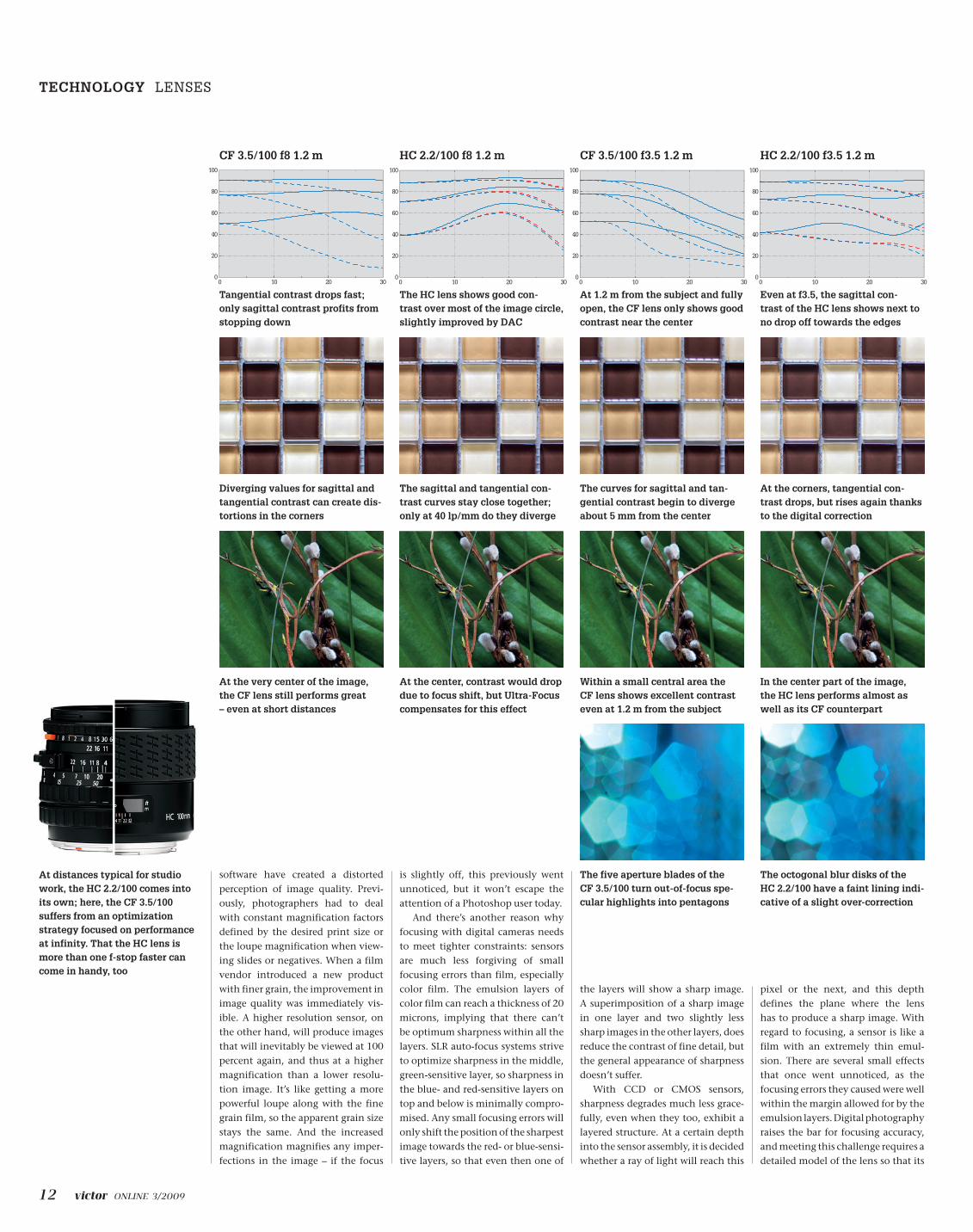
tangential contrast drops fast; only sagittal contrast profits from stopping down
Diverging values for sagittal and tangential contrast can create dis-tortions in the corners
At the very center of the image, the cF lens still performs great – even at short distances
cF 3.5/100 f8 1.2 m
the hc lens shows good con- trast over most of the image circle, slightly improved by DAc
the sagittal and tangential con-trast curves stay close together; only at 40 lp/mm do they diverge
At the center, contrast would drop due to focus shift, but Ultra-Focus compensates for this effect
hc 2.2/100 f8 1.2 m
At 1.2 m from the subject and fully open, the cF lens only shows good contrast near the center
the curves for sagittal and tan-gential contrast begin to diverge about 5 mm from the center
Within a small central area the cF lens shows excellent contrast even at 1.2 m from the subject
cF 3.5/100 f3.5 1.2 m
even at f3.5, the sagittal con- trast of the hc lens shows next to no drop off towards the edges
At the corners, tangential con-trast drops, but rises again thanks to the digital correction
the octogonal blur disks of the hc 2.2/100 have a faint lining indi-cative of a slight over-correction
the five aperture blades of the cF 3.5/100 turn out-of-focus spe-cular highlights into pentagons
in the center part of the image, the hc lens performs almost as well as its cF counterpart
hc 2.2/100 f3.5 1.2 m
software have created a distorted perception of image quality. Previ-ously, photographers had to deal with constant magnification factors defined by the desired print size or the loupe magnification when view-ing slides or negatives. When a film vendor introduced a new product with finer grain, the improvement in image quality was immediately vis-ible. A higher resolution sensor, on the other hand, will produce images that will inevitably be viewed at 100 percent again, and thus at a higher magnification than a lower resolu-tion image. It’s like getting a more powerful loupe along with the fine grain film, so the apparent grain size stays the same. And the increased magnification magnifies any imper-fections in the image – if the focus
is slightly off, this previously went unnoticed, but it won’t escape the attention of a Photoshop user today.
And there’s another reason why focusing with digital cameras needs to meet tighter constraints: sensors are much less forgiving of small focusing errors than film, especially color film. The emulsion layers of color film can reach a thickness of 20 microns, implying that there can’t be optimum sharpness within all the layers. SLR auto-focus systems strive to optimize sharpness in the middle, green-sensitive layer, so sharpness in the blue- and red-sensitive layers on top and below is minimally compro-mised. Any small focusing errors will only shift the position of the sharpest image towards the red- or blue-sensi-tive layers, so that even then one of
the layers will show a sharp image. A superimposition of a sharp image in one layer and two slightly less sharp images in the other layers, does reduce the contrast of fine detail, but the general appearance of sharpness doesn’t suffer.
With CCD or CMOS sensors, sharpness degrades much less grace-fully, even when they too, exhibit a layered structure. At a certain depth into the sensor assembly, it is decided whether a ray of light will reach this
pixel or the next, and this depth defines the plane where the lens has to produce a sharp image. With regard to focusing, a sensor is like a film with an extremely thin emul-sion. There are several small effects that once went unnoticed, as the focusing errors they caused were well within the margin allowed for by the emulsion layers. Digital photography raises the bar for focusing accuracy, and meeting this challenge requires a detailed model of the lens so that its
At distances typical for studio work, the hc 2.2/100 comes into its own; here, the cF 3.5/100 suffers from an optimization strategy focused on performance at infinity. that the hc lens is more than one f-stop faster can come in handy, too
technology lenses
0
20
40
60
80
100
0 10 20 30
HC100 f/3.5 1:10
0
20
40
60
80
100
0 10 20 30
CF100 f/3.5 1:10
0
20
40
60
80
100
0 10 20 30
HC100 f/8 1:10
0
20
40
60
80
100
0 10 20 30
CF100 f/8 1:10
13 ONLINE 3/2009
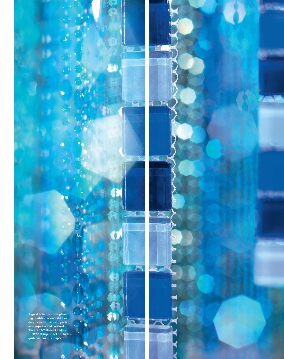
A good bokeh, i.e. the pleas-ing rendition of out-of-focus detail can be just as important as sharpness and contrast. the cF 3.5/100 (left) and the hc 2.2/100 (right), both at f4, fare quite well in this respect

14 ONLINE 3/2009
focus shift, focusing would be slightly off at larger or smaller apertures. With small apertures, the increase in depth of field is sufficient to mask this effect, but with a fully open lens, a high-resolution CCD might reveal a discernible lack of sharp-ness. Since the offset between the optimum focus position for a given aperture and the position found by the AF sensor with the lens fully open is known, an H System camera can easily compensate for focus shift, ensuring maximally sharp images at any aperture setting.
Ultra-Focus, of which the com-pensation for focus shift is a part, shows how knowing your cam-era system inside out pays off with improvements in image quality. This principle extends to the post-exposure part of the workflow where Hasselblad’s Digital Auto Correction (DAC) takes care of fine honing the image quality in FlexColor or Pho-cus. DAC relies on the lens model for predicting residual imperfections, namely chromatic aberration (level I), distortion (level II), and vignetting (level III). Thus informed about what differentiates the image as it is from the image as it should have been, the raw converter can apply the appro-priate corrections, relocating pixels to their rightful place, either for all three color channels individually (DAC level I) or collectively (level II), and adjusting each pixel’s brightness (level III).
DAC level I, the correction of chromatic aberration, also removes a major cause for the loss of sharpness
technology lenses
source will propagate through the lens elements and the diaphragm, taking all the effects of refraction and diffraction into account. The result of a simulation can be presented in a multitude of ways; from a repre-sentation of the image formed in the image plane, to various diagrams showing MTF curves, or mapping contrast changes with the focus set-ting.
Apart from taking these results as tips for further improvements in lens design, the simulation models retain their usefulness long after the devel-opment is complete. When the lens prototype arrives from Japan, it is subject to Hasselblad lab tests on an optical bench; comparing its actual performance to the performance predicted by the simulation soft-ware. Discrepancies detected at this stage can either point to production
behavior can be accurately predicted under all possible circumstances.
real and virTual lenses
Well before Fujinon begins grinding glass into the desired lens shapes, the lens exists as a simulation model on a computer. This virtual lens depicts all the characteristics of the real thing, not just the desired ones. Performance parameters have been specified as goals for optimization and any residual aberrations, any compromises necessary for achiev-ing the design objectives are just as accurately modeled. The lens design software can, for example, probe the virtual lens with an equally virtual pin-hole light source, set at a certain distance and angle to calculate how the light rays emanating from this
issues to be resolved by Fujinon, or to a substandard choice of optimiza-tion compromises that needs to be adjusted. After the simulation model has fulfilled its role in improving the design and the lens goes into pro-duction, the model assumes a new role informing the camera electron-ics and the raw conversion software about the peculiarities inherent in that particular lens.
For fine detail of a given orienta-tion, spatial frequency, and distance; the software can predict the contrast levels produced by the lens at any focus position and aperture setting. From these data points, tables of cor-rection coefficients are calculated that allow the auto-focus system to compensate for aperture-dependent focus shift. An ideal lens would con-centrate parallel rays of light to an incredibly small focus point, but in reality, spherical aberration turns this point into a fuzzy blob. Light rays entering a spherical lens far from the optical axis are refracted more strongly than those entering near the axis, so there is no common focal point. Even when spherical aberra-tion is corrected for, this correction will never be perfect; actual lenses will be either under- or over-corrected and modern lens designs will tend to over-correct. When stopping down, rays far from the optical axis are excluded and the point of optimum contrast will shift, resulting in back-focus with under-corrected lenses and front-focus with over-corrected ones. The TTL auto-focus sensor uses f6.7, so without compensating for
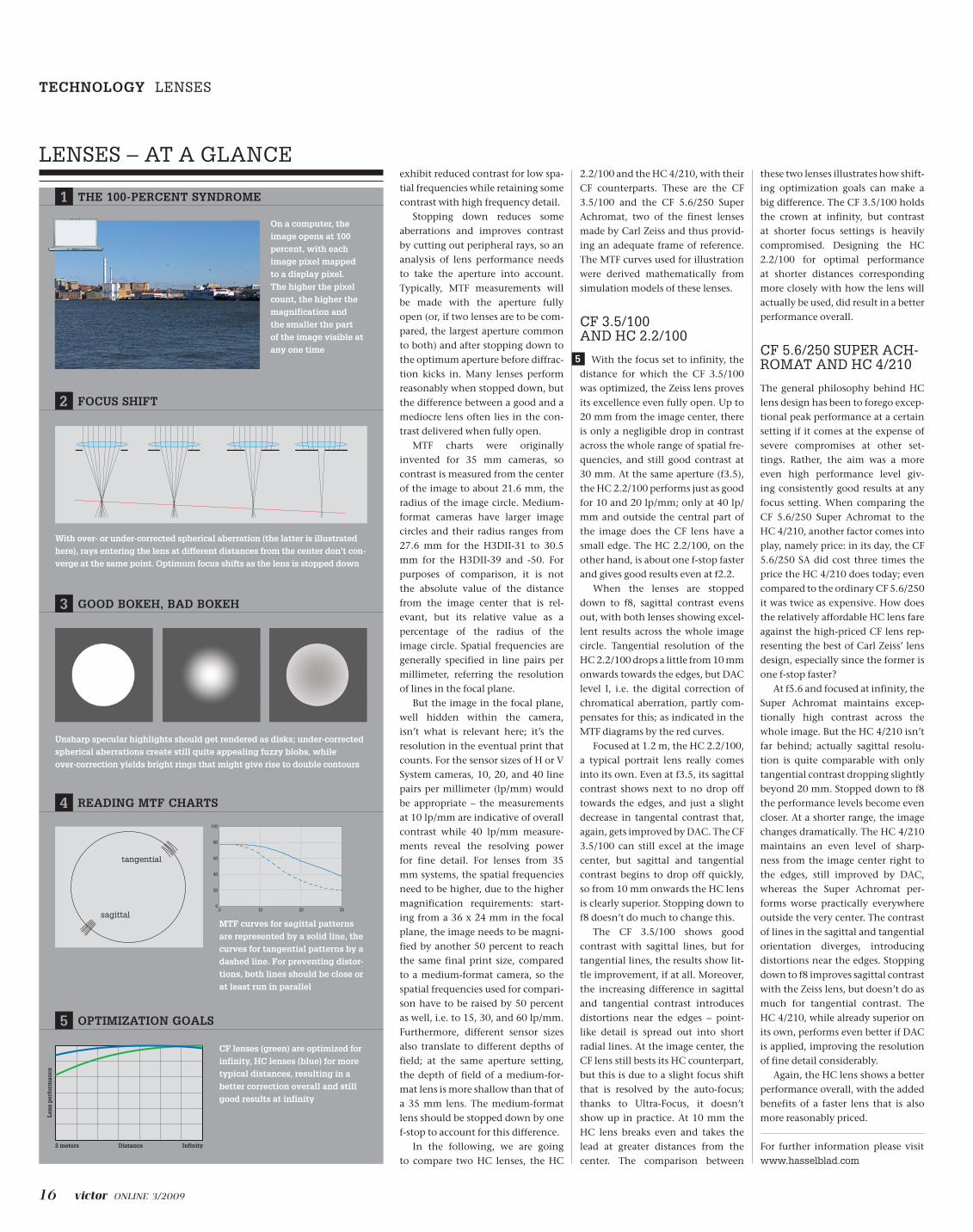
being optimized for infinity, the stopped down cF lens shows no weaknesses whatsoever
the cF 3.5/100 makes a good land-scape lens with excellent resolution across the whole image
cF 3.5/100 f8 infinity
the hc lens shows good results; tangential contrast drops a little from 10 mm onwards
tangential resolution is improved by the digital correction of chromatic aberration (DAc)
hc 2.2/100 f8 infinity
even fully open, the cF lens produces good contrast; excellent from the center to 20 mm
Again the optimization for infinity results in outstanding perfor-mance at long distance settings
cF 3.5/100 f3.5 infinity
Up to 20 lp/mm, the hc lens per-forms nearly as well; at 40 lp/mm, contrast drops a little faster
Despite its different optimization goals, the performance is still quite good even near infinity
hc 2.2/100 f3.5 infinity
near infinity, the cF 3.5/100 has a slight edge, performance-wise, but the hc 2.2/100 can hold its own
A view of gothenburg’s harbor, not far from the hasselblad building, provided the near infinity detail for a comparison between the cF 3.5/100 (left) and the hc 2.2/100 (right)
2
0
20
40
60
80
100
0 10 20 30
CF100 f/8 infinity
0
20
40
60
80
100
0 10 20 30
HC100 f/8 infinity
0
20
40
60
80
100
0 10 20 30
CF100 f/3.5 infinity
0
20
40
60
80
100
0 10 20 30
HC100 f/3.5 infinity
15 ONLINE 3/2009
and resolution towards the edges of the image. After the correction, the resolution of the digital image can be even better than that of the optical image in the sensor plane. With silver-halide photography, the performance of the lens defined an upper limit of image quality one could attain; with digital photogra-phy, it is just the starting point.
WhaT Makes a fine lens
Unless a camera is used for repro-duction, photographic subjects will generally be three-dimensional. The plane of focus cuts out a slice of the scene that will be rendered sharp, so there is a contrast between sharpness and unsharpness at different depths into the scene that can be used to good effect. The requirements for a good lens are thus twofold: within the depth of field, subjects should be rendered sharp, i.e. with a maximum of contrast even in the finest detail. Subjects out of focus should appear unsharp, but in an aesthetically pleasing way, a quality that is much harder to pin down exactly. Still, you recognize it when you see it, and it can make a real difference between lenses of comparable sharpness.
For each CCD pixel, there is a cone of light converging on it, and from the pixel’s point of view, the differ-ence between sharpness and blur hinges on the origin of those light rays. If the image is in focus at this
point, all the rays hitting the pixel originate from the same point in the scene; if the image is out of focus, the rays originate from different sources. The mixture of light from different sources in the scene introduces blur. Even for the in-focus case, the perfect double cone of light – all the light emanating from a point that reaches lens converges in the same point in the image plane – is an idealization.
With an uncorrected lens, aberra-tions such as astigmatism, spherical aberration, or chromatic aberration would contribute to turn the ideal point into a fuzzy blob spreading over several pixels, reducing the contrast at the edges between areas of different brightness or color. The effect of aberrations increases with the distance from the image center, resulting in a gradual loss of contrast, sharpness, and resolution towards the corners. It is the task of the lens designer to guarantee a high degree of correction for all kinds of aber-rations to maintain good contrast across all of the image area, and for all or at least most relevant focusing distances. Quite often, lens designs have been optimized for infinity, whereas in a typical studio setting, subjects are just a few meters away. Another aspect to keep in mind is the repercussions lens corrections have for the imaging of out-of-focus detail.
The characteristic way in which a lens renders out-of-focus subjects is called “bokeh”, an English spelling
approximating the Japanese ぼけ meaning, among other things, “blur”. What constitutes “good” or “bad” bokeh – the terms “pleas-ant” or “unpleasant” might be more appropriate – is open to debate, as are the main factors influencing bokeh.
When specular highlights in the out-of-focus background appear as blur disks, these disks are images of the aperture and their shape cor-responds to that of the diaphragm. From polygon shaped rather than round blur disks one can easily deter-mine the number of aperture blades. These shapes are rarely distracting, though, and increasing the number of blades doesn’t improve bokeh as much to be worth bothering. Still, in extreme cases the aperture can be a factor: catadioptric (mirror) lenses that enjoyed a short-lived popular-ity during the 1980s had an annular opening due to their secondary mir-ror, rendering unsharp highlights as bright rings and creating double images of out-of-focus lines. Both kinds of optical artifacts were highly distracting.
The biggest factor influencing bokeh is the amount of spherical aberration. A perfectly corrected lens would have blur disks with uniform brightness and sharp edges. When some of the spherical aberration stays uncorrected, the edge of the disk gets fuzzy, but the bokeh would still be pleasant, maybe even more so than with a perfectly corrected lens. An over-corrected lens would create blur
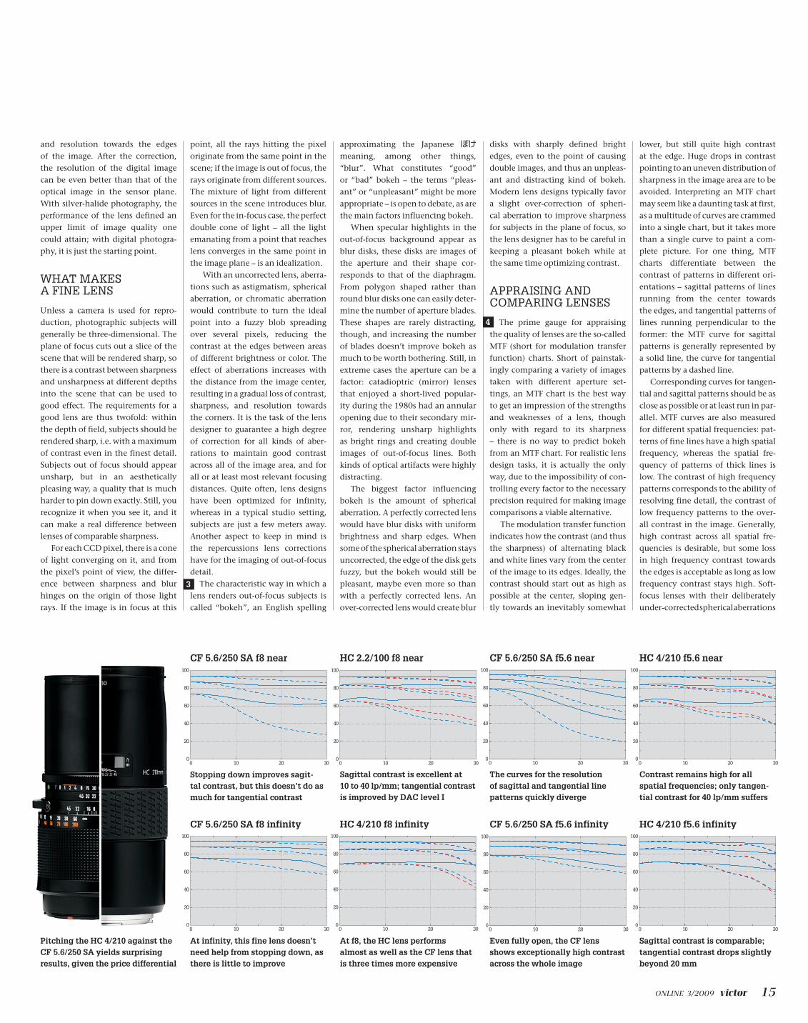
stopping down improves sagit- tal contrast, but this doesn’t do as much for tangential contrast
cF 5.6/250 sA f8 near
sagittal contrast is excellent at 10 to 40 lp/mm; tangential contrast is improved by DAc level i
hc 2.2/100 f8 near
At infinity, this fine lens doesn’t need help from stopping down, as there is little to improve
cF 5.6/250 sA f8 infinity
At f8, the hc lens performs almost as well as the cF lens that is three times more expensive
hc 4/210 f8 infinity
the curves for the resolution of sagittal and tangential line patterns quickly diverge
even fully open, the cF lens shows exceptionally high contrast across the whole image
cF 5.6/250 sA f5.6 infinity
sagittal contrast is comparable; tangential contrast drops slightly beyond 20 mm
hc 4/210 f5.6 infinity
cF 5.6/250 sA f5.6 near
contrast remains high for all spatial frequencies; only tangen-tial contrast for 40 lp/mm suffers
hc 4/210 f5.6 near
Pitching the hc 4/210 against the cF 5.6/250 sA yields surprising results, given the price differential
disks with sharply defined bright edges, even to the point of causing double images, and thus an unpleas-ant and distracting kind of bokeh. Modern lens designs typically favor a slight over-correction of spheri-cal aberration to improve sharpness for subjects in the plane of focus, so the lens designer has to be careful in keeping a pleasant bokeh while at the same time optimizing contrast.
appraising and coMparing lenses
The prime gauge for appraising the quality of lenses are the so-called MTF (short for modulation transfer function) charts. Short of painstak-ingly comparing a variety of images taken with different aperture set-tings, an MTF chart is the best way to get an impression of the strengths and weaknesses of a lens, though only with regard to its sharpness – there is no way to predict bokeh from an MTF chart. For realistic lens design tasks, it is actually the only way, due to the impossibility of con-trolling every factor to the necessary precision required for making image comparisons a viable alternative.
The modulation transfer function indicates how the contrast (and thus the sharpness) of alternating black and white lines vary from the center of the image to its edges. Ideally, the contrast should start out as high as possible at the center, sloping gen-tly towards an inevitably somewhat
lower, but still quite high contrast at the edge. Huge drops in contrast pointing to an uneven distribution of sharpness in the image area are to be avoided. Interpreting an MTF chart may seem like a daunting task at first, as a multitude of curves are crammed into a single chart, but it takes more than a single curve to paint a com-plete picture. For one thing, MTF charts differentiate between the contrast of patterns in different ori-entations – sagittal patterns of lines running from the center towards the edges, and tangential patterns of lines running perpendicular to the former: the MTF curve for sagittal patterns is generally represented by a solid line, the curve for tangential patterns by a dashed line.
Corresponding curves for tangen-tial and sagittal patterns should be as close as possible or at least run in par-allel. MTF curves are also measured for different spatial frequencies: pat-terns of fine lines have a high spatial frequency, whereas the spatial fre-quency of patterns of thick lines is low. The contrast of high frequency patterns corresponds to the ability of resolving fine detail, the contrast of low frequency patterns to the over-all contrast in the image. Generally, high contrast across all spatial fre-quencies is desirable, but some loss in high frequency contrast towards the edges is acceptable as long as low frequency contrast stays high. Soft-focus lenses with their deliberately under-corrected spherical aberrations
3
4
0
20
40
60
80
100
0 10 20 30
CF250SA f/8 1:10
0
20
40
60
80
100
0 10 20 30
HC210 f/8 1:10
0
20
40
60
80
100
0 10 20 30
CF250SA f/8 infinity
0
20
40
60
80
100
0 10 20 30
HC210 f/8 infinity
0
20
40
60
80
100
0 10 20 30
CF250SA f/5.6 infinity
0
20
40
60
80
100
0 10 20 30
HC210 f/5.6 infinity
0
20
40
60
80
100
0 10 20 30
CF250SA f/5.6 1:10
0
20
40
60
80
100
0 10 20 30
HC210 f/5.6 1:10
16 ONLINE 3/2009
exhibit reduced contrast for low spa-tial frequencies while retaining some contrast with high frequency detail.
Stopping down reduces some aberrations and improves contrast by cutting out peripheral rays, so an analysis of lens performance needs to take the aperture into account. Typically, MTF measurements will be made with the aperture fully open (or, if two lenses are to be com-pared, the largest aperture common to both) and after stopping down to the optimum aperture before diffrac-tion kicks in. Many lenses perform reasonably when stopped down, but the difference between a good and a mediocre lens often lies in the con-trast delivered when fully open.
MTF charts were originally invented for 35 mm cameras, so contrast is measured from the center of the image to about 21.6 mm, the radius of the image circle. Medium-format cameras have larger image circles and their radius ranges from 27.6 mm for the H3DII-31 to 30.5 mm for the H3DII-39 and -50. For purposes of comparison, it is not the absolute value of the distance from the image center that is rel-evant, but its relative value as a percentage of the radius of the image circle. Spatial frequencies are generally specified in line pairs per millimeter, referring the resolution of lines in the focal plane.
But the image in the focal plane, well hidden within the camera, isn’t what is relevant here; it’s the resolution in the eventual print that counts. For the sensor sizes of H or V System cameras, 10, 20, and 40 line pairs per millimeter (lp/mm) would be appropriate – the measurements at 10 lp/mm are indicative of overall contrast while 40 lp/mm measure-ments reveal the resolving power for fine detail. For lenses from 35 mm systems, the spatial frequencies need to be higher, due to the higher magnification requirements: start-ing from a 36 x 24 mm in the focal plane, the image needs to be magni-fied by another 50 percent to reach the same final print size, compared to a medium-format camera, so the spatial frequencies used for compari-son have to be raised by 50 percent as well, i.e. to 15, 30, and 60 lp/mm. Furthermore, different sensor sizes also translate to different depths of field; at the same aperture setting, the depth of field of a medium-for-mat lens is more shallow than that of a 35 mm lens. The medium-format lens should be stopped down by one f-stop to account for this difference.
In the following, we are going to compare two HC lenses, the HC
2.2/100 and the HC 4/210, with their CF counterparts. These are the CF 3.5/100 and the CF 5.6/250 Super Achromat, two of the finest lenses made by Carl Zeiss and thus provid-ing an adequate frame of reference. The MTF curves used for illustration were derived mathematically from simulation models of these lenses.
cf 3.5/100 and hc 2.2/100
With the focus set to infinity, the distance for which the CF 3.5/100 was optimized, the Zeiss lens proves its excellence even fully open. Up to 20 mm from the image center, there is only a negligible drop in contrast across the whole range of spatial fre-quencies, and still good contrast at 30 mm. At the same aperture (f3.5), the HC 2.2/100 performs just as good for 10 and 20 lp/mm; only at 40 lp/mm and outside the central part of the image does the CF lens have a small edge. The HC 2.2/100, on the other hand, is about one f-stop faster and gives good results even at f2.2.
When the lenses are stopped down to f8, sagittal contrast evens out, with both lenses showing excel-lent results across the whole image circle. Tangential resolution of the HC 2.2/100 drops a little from 10 mm onwards towards the edges, but DAC level I, i.e. the digital correction of chromatical aberration, partly com-pensates for this; as indicated in the MTF diagrams by the red curves.
Focused at 1.2 m, the HC 2.2/100, a typical portrait lens really comes into its own. Even at f3.5, its sagittal contrast shows next to no drop off towards the edges, and just a slight decrease in tangental contrast that, again, gets improved by DAC. The CF 3.5/100 can still excel at the image center, but sagittal and tangential contrast begins to drop off quickly, so from 10 mm onwards the HC lens is clearly superior. Stopping down to f8 doesn’t do much to change this.
The CF 3.5/100 shows good contrast with sagittal lines, but for tangential lines, the results show lit-tle improvement, if at all. Moreover, the increasing difference in sagittal and tangential contrast introduces distortions near the edges – point-like detail is spread out into short radial lines. At the image center, the CF lens still bests its HC counterpart, but this is due to a slight focus shift that is resolved by the auto-focus; thanks to Ultra-Focus, it doesn’t show up in practice. At 10 mm the HC lens breaks even and takes the lead at greater distances from the center. The comparison between
these two lenses illustrates how shift-ing optimization goals can make a big difference. The CF 3.5/100 holds the crown at infinity, but contrast at shorter focus settings is heavily compromised. Designing the HC 2.2/100 for optimal performance at shorter distances corresponding more closely with how the lens will actually be used, did result in a better performance overall.
cf 5.6/250 super ach-roMaT and hc 4/210
The general philosophy behind HC lens design has been to forego excep-tional peak performance at a certain setting if it comes at the expense of severe compromises at other set-tings. Rather, the aim was a more even high performance level giv-ing consistently good results at any focus setting. When comparing the CF 5.6/250 Super Achromat to the HC 4/210, another factor comes into play, namely price: in its day, the CF 5.6/250 SA did cost three times the price the HC 4/210 does today; even compared to the ordinary CF 5.6/250 it was twice as expensive. How does the relatively affordable HC lens fare against the high-priced CF lens rep-resenting the best of Carl Zeiss’ lens design, especially since the former is one f-stop faster?
At f5.6 and focused at infinity, the Super Achromat maintains excep-tionally high contrast across the whole image. But the HC 4/210 isn’t far behind; actually sagittal resolu-tion is quite comparable with only tangential contrast dropping slightly beyond 20 mm. Stopped down to f8 the performance levels become even closer. At a shorter range, the image changes dramatically. The HC 4/210 maintains an even level of sharp-ness from the image center right to the edges, still improved by DAC, whereas the Super Achromat per-forms worse practically everywhere outside the very center. The contrast of lines in the sagittal and tangential orientation diverges, introducing distortions near the edges. Stopping down to f8 improves sagittal contrast with the Zeiss lens, but doesn’t do as much for tangential contrast. The HC 4/210, while already superior on its own, performs even better if DAC is applied, improving the resolution of fine detail considerably.
Again, the HC lens shows a better performance overall, with the added benefits of a faster lens that is also more reasonably priced.
lenses – aT a glance
2 FocUs shiFt
With over- or under-corrected spherical aberration (the latter is illustrated here), rays entering the lens at different distances from the center don’t con-verge at the same point. optimum focus shifts as the lens is stopped down
4 ReADing MtF chARts
MtF curves for sagittal patterns are represented by a solid line, the curves for tangential patterns by a dashed line. For preventing distor-tions, both lines should be close or at least run in parallel
5 oPtiMiZAtion goAls
cF lenses (green) are optimized for infinity, hc lenses (blue) for more typical distances, resulting in a better correction overall and still good results at infinity
For further information please visit www.hasselblad.com
on a computer, the image opens at 100 percent, with each image pixel mapped to a display pixel. the higher the pixel count, the higher the magnification and the smaller the part of the image visible at any one time
3 gooD bokeh, bAD bokeh
Unsharp specular highlights should get rendered as disks; under-corrected spherical aberrations create still quite appealing fuzzy blobs, while over-correction yields bright rings that might give rise to double contours
2 meters Distance infinity
len
s p
erfo
rman
ce
1 the 100-PeRcent synDRoMe
technology lenses
5
0
20
40
60
80
100
0 10 20 30