cfd analysis on flow through a resistance muffler of lcv...
TRANSCRIPT
International Journal of Science, Technology and Society 2015; 3(4): 132-145 Published online June 6, 2015 (http://www.sciencepublishinggroup.com/j/ijsts) doi: 10.11648/j.ijsts.20150304.16 ISSN: 2330-7412 (Print); ISSN: 2330-7420 (Online)
CFD Analysis on Flow Through a Resistance Muffler of LCV Diesel Engine
Pradyumna Saripalli, K. Sankaranarayana
Mechanical Engineering, Gitam Institute of Technology, Gitam University, Visakhapatnam (A.P), India
Email address: [email protected] (P. Saripalli)
To cite this article: Pradyumna Saripalli, K. Sankaranarayana. CFD Analysis on Flow Through a Resistance Muffler of LCV Diesel Engine. International
Journal of Science, Technology and Society. Vol. 3, No. 4, 2015, pp. 132-145. doi: 10.11648/j.ijsts.20150304.16
Abstract: The exhaust pollution has become one of the important problems of environment pollution with applications in automobile industry, and the exhausted muffler has been paid attention to improve the performance of engines. Computational Fluid Dynamics (CFD) method was used to explore the aerodynamic performance of the muffler. Resistance muffler research relates with the fields of acoustics, fluid dynamics, heat transfer and mechanism design. The project report simulates the field by numerical method with Cosmos Flow and analyses the effect which the internal flow field has on the performance of the muffler. With this method the pressure distribution in the muffler is simulated and the pressure loss is predicted for the structure modification. The experiment results verify that the assembly performance of the muffler modified is better than the original muffler.
Keywords: CFD, Muffler, Cosmos Flow, Field Flow, Acoustics, Pressure Loss
1. Introduction
Internal combustion engines are the major power sources for automobiles and also the work developers for the small scale power generation units. They operate by taking in a mixture of air and fuel (petrol engines) or by taking only air (diesel engines) and compressing it followed by combustion. At this stage power is produced while combustion of the fuel and ultimately exhaust gases are produced and have to be pushed out of engine cylinder so that there is ample volume left for the fresh charge to be induced.
The exhaust from the automobiles is at a high pressure and leads to generation of noise while rejection to the atmosphere. To reduce the exhaust pressure and subsequently to reduce the noise a muffler is improvised in the exhaust system of the automobiles.
A muffler is a device that is used for reducing the amount of noise produced by the engines. The basic constructions of muffler usually consist of the tubular metal jacket, perforated tubes and the expansion chamber. The arrangement of these components will guide the exhaust gas to flow from the inlet pipe of the muffler to the outlet (tail pipe). Inside the muffler, the noise from the exhaust gas will be cancelled out by the basic physics principle on noise cancellation before the gas flows out to the atmosphere. The noise cancellation will
reduce the noise that radiated by the vehicle to the surroundings. The present day mufflers that are being incorporated in automobiles are majorly of two types:
1. Reflective mufflers 2. Dissipative mufflers A reflective muffler consists of a number of tubular
elements of different transverse dimensions joined together so as to cause, at every junction, impedance mismatch and hence reflection of substantial part of the incident acoustic energy back to the source, whereas dissipative mufflers consist of ducts lined on the inside with acoustically absorptive materials. Both mufflers are having different construction, geometry, and principles in their application.
In resistance or reflective mufflers the noise attenuation is done by the basic physics principle of wave cancellation. The steady or mean flow should be allowed to pass unimpeded through the muffler while the fluctuating flow which is associated with the acoustic pressure fluctuation is impeded. If the steady flow is not significantly impeded the so-called ‘back pressure’ will be very low and the engine will function more efficiently. Because of the back pressure the volumetric efficiency decreases and specific fuel consumption increases. Hence there is a need for an optimum muffler design.

International Journal of Science, Technology and Society 2015; 3(4): 132-145 133
The various factors that affect the muffler performance are 1. Muffler design 2. Muffler material 3. Restriction to the flow inside the muffler Muffler consists of four main components I. Inlet pipe II. Outlet pipe III. Muffler shell IV. Perforated tube When the exhaust gases from inlet pipe pass through the
perforations inside the shell, the gases get scattered in different directions. After reflection from the inside surface of the shell, the sound cancellation of waves occur. The gases pass through the perforations multiple times and even get reflected from the shell surface. Due to the combined effect of these, the level of sound at the muffler outlet is reduced significantly. After doing a lot of research and experimentation it has been found that the reduction in the noise is inversely proportional to the backpressure, which is not a desired characteristic and hence an optimum muffler design has to be implemented so that there is maximum noise reduction and minimum possible back pressure.
The flow through the muffler and variation of various parameters such as velocity and pressure along the length of the model can be accurately demonstrated with the help of CFD analysis which display accurate results within a short span of time.
2. Literature Survey
Erdem Özdemir et al [1] The model comprised of a perforated inlet and had four pipes between the expansion chambers. The analysis was performed by changing the lengths of the front, middle and expansion chambers as it was found that the noise attenuation can be done by increasing the length of the middle chamber. The air inlet was considered at 473 K and the air was considered to be incompressible ideal gas for the analysis. It is observed that 30% reduction on length of rear chamber did not make any difference on acoustic characteristics with base muffler model. To generate cross flow, inlet and outlet pipe's perforated part stand in the middle chamber. A decrease at the length of middle chamber prevents the cross flow. Thus, It can be concluded that a greater pressure loss occur at this model.
Sileshi Kore et al [2] The analysis was performed in ANSYS FLUENT and the meshing of the geometry was done using GAMBIT. The muffler was designed for the simulation of the Alfa Romeo 1995 model. The solver implemented was a 2-D, segregated implicit solver with 2nd order implicit time stepping. Second order upwind discretization was used for the density, momentum, energy, turbulent kinetic energy and the turbulent dissipation rate equations. The inlet conditions were considered as pressure inlet of air (ideal gas) at a pressure of 101325 Pa and 300 K
temperature. In this case the inlet velocity is normally 80 m/s and the outlet boundary condition has been set at atmospheric pressure. From the above analysis it was observed that the maximum transmission loss is around 14dB with an optimal amount of backpressure for the developed model.
Tutunea et al [3] Here the model was generated using SOLIDWORKS 3D modelling package and the analysis and simulation of the internal flow was carried out using ANSYS FLUENT 14. The observations were made on a muffler which had three main chambers and the middle chamber had a perforated tube. The boundary conditions were incorporated as velocity inlet, where the velocity was considered as 25m/s and at 280 Deg C of temperature. It was observed that there was a considerable decrease in the pressure at the outlet of the muffler and the results were in good agreement.
The flow of the exhaust was assessed by generating a CAD model and simulating them in the virtual environment of ANSYS fluent. The thermal and the acoustic parameters were analysed and the performance of the designed muffler were evaluated. [4, 5, 6, 7, 8, 9, 10, 11, 12, 13].
3. Basic Theory
3.1. Theoretical Computation
Cylinder firing rate (CFR) = Engine Speed in RPM/60 …. For a two stroke engine= Engine Speed in RPM/120 ….For a four-stroke engine
Engine firing rate (EFR) = n X (CFR), where n is the number of cylinders
3.2. Muffler Volume (Vm) Calculation
Vm = Vf x [ π/4 (D2xl) ] x (no of cylinders /2 )
Where Vf is the volume factor, d is the bore and l is the stroke of an internal combustion engine.
4. Problem Formulation
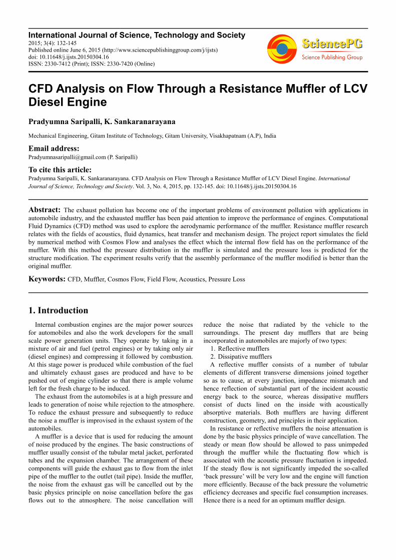
The exhaust system is defined as the hardware necessary to vent the exhaust from the vehicle beginning at the exhaust plane defined by the engine manufacturer and necessary to isolate the exhaust thermally from vehicle structures. The virtual design of the exhaust muffler, as a minimum, include an accurate estimate of space required for the exhaust, backpressure to the engine, system weight, gas species distributions, gas temperature distributions, the interaction of the plume with external surfaces both on the vehicle and the ground, and the thermal interaction of the exhaust system with external surfaces through internal convection, conduction, and radiation. The muffler being simulated is being designed as per the engine output of Maruti Ciaz.

134 Pradyumna Saripalli and K. Sankaranarayana: CFD Analysis on Flow Through a Resistance Muffler of LCV Diesel Engine
Fig. 1. CATIA model of the designed muffler.
Case Study – LCV Diesel engine vehicle (Ciaz) Engine Data: Bore (D) = 69.6 mm Stroke (L) = 82 mm No. Cylinders (n) = 4 Engine power (P) = 88.7 bhp at 4000 RPM Muffler Volume Calculations: Swept volume per cylinder = 0.25 (π xD2xl)= 0.25 (3.14 x
69.62x 82) (Vs) = 0.3119 lit. Total swept volume in litres = 4x0.3119= 1.247 Lit. Volume to be considered for calculation = 0.5 x Vs x n=
0.6239 Lit Silencer volume: Volume of silencer must be at least 12 to
25 times the volume considered [6]. Volume can be adjusted
depending on the space constraint. Factor considered is = 22 Silencer volume = factor x consider volume = 13.73 Lit Diameter of Muffler Calculations: Vm = 0.25x π x d2 x l 0.01373 = 0.25x π x d2 x 0.5 d = 0.187 m= 187 mm Diameter of Pipe Calculations: As per the standards of the supercritical grade of mufflers,
the diameter of the body should be about three times than the exhaust pipe diameter.
d = 3* d exhaust
187= 3* d exhaust
d exhaust = 62.33 mm
Fig. 2. Internal view of designed muffler (model 1).
International Journal of Science, Technology and Society 2015; 3(4): 132-145 135
Fig. 3. Internal view of designed muffler (model 2).
Table 1. Material properties.
Property Units Value
Density kg/m3 7900
Specific heat J/(kg*K) 500
Thermal Conductivity W/(m*K) 16.2
Conductivity type isotropic Isotropic
Table 2. Dimensional data.
Entity Dimensions (mm)
Shell length 500
Shell Dia 187
Inlet pipe Dia 62.33
Inlet pipe length 85
Outlet pipe Dia 62.33
Outlet pipe length 85
5. Problem Solution
After the construction of exhaust muffler model in CATIA it is analysed in ANSYS FLUENT 14.5. The FLUENT analysis is carried out by considering three types of inlet boundary conditions.
1. Velocity inlet 2. Pressure inlet
Table 3. Initial values for velocity inlet as the inlet boundary condition.
Area (m2) 0.003051 Temperature (K) 470 Viscosity (kg/ms) 2.7e-05 Enthalpy (J/kg) 749575.3 Density (kg/m3) 0.696 Length (mm) 500 Velocity(m/s) 80 Ratio of specific heats 1.4
Table 4. Initial values for pressure inlet as the inlet boundary condition.
Area (m2) 0.003051
Temperature (K) 470
Viscosity (kg/ms) 2.7e-05
Enthalpy (J/kg) 749575.3
Density (kg/m3) 0.696
Length (mm) 500
Velocity(m/s) 80
6. Results and Discussion
The mean flow performance of the muffler considered in the flow analysis has been assessed. The results of the simulated muffler models obtained with the use of CFD modelling are very encouraging.
From Figure 4 it has been observed that for a velocity inlet boundary condition in model 1, the exhaust from the engine enters the muffler at a velocity of 80m/s and increases to a

136 Pradyumna Saripalli and K. Sankaranarayana: CFD Analysis on Flow Through a Resistance Muffler of LCV Diesel Engine
magnitude of about 133 m/s in the expansion chamber once it passes through the opening. This is observed as a result of decrease in the flow area the pressure increases and subsequently the velocity increases. After this the gases get spread in the chamber and they enter the next chamber from the other two splits. Then on hitting the baffle they swirl and come out of the exhaust at an increased speed of about 106m/s.
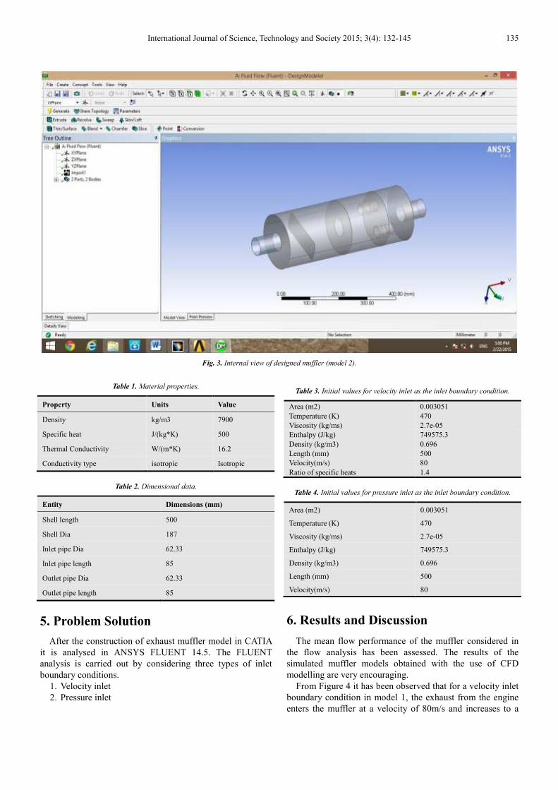
Also from figure 9 we observe that for a pressure inlet boundary condition in model 1, the gases enter the muffler at a pressure of 3.02 bar and hit the baffle. On making the impact the exhaust recedes a bit and swirls are observed in that particular entrance chamber. The swirls have the pressure magnitude of about 2.47 bar. The gases enter the second chamber from the baffle openings at top and bottom and hence it has been observed that the pressure intensity is more near the walls in this chamber and has a magnitude of about 2.8 bar. This is because of the fact that due to the presence of the slits or openings near the top and the bottom of the baffle, the pressurized gas or exhaust is directed towards the walls of the muffler and on hitting them the exhaust comes away from the walls. From the second chamber the exhaust enters the third chamber through an opening at the center of a baffle and hence it is observed that there is a 2.26 bar pressure region almost throughout the center of the chamber and the rest has a swirl region with a pressure of 1.5bar. This is due to the reason that as the area decreases the pressure increases
and the velocity decreases. So as the pressure is more hence there is a constant or maintained region in the chamber. Again the gases hit the baffle and enter the next chamber with a similar effect as it was observed in the second chamber but with a reduced pressure intensity of about 1.93 bar near the walls. Finally the exhaust gases come out of the outlet pipe at a pressure of 1.61 bar.
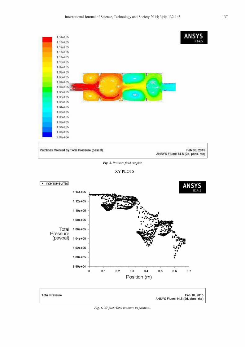
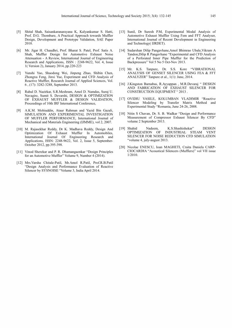
In model 2 as evident from figure 6 it has been observed that the gases enter the inlet pipe at a pressure of 3.01 bar and on hitting the baffle there occurs a swirl region in the first chamber which has a pressure intensity of 2.9 bar. The flow of the gases was more or less similar as that in model 1but due to the changed arrangement of the baffles more intensity of pressure was observed near the walls. The velocity magnitude over this region is nearly 310 m/s according to figure 17. Due to the reduction in the flow area the velocity of the gases increase and reach a maximum intensity of 620 m/s. The flow pattern remains similar to that of model 1 further and the gases come out of the outlet pipe at a speed of 372 m/s and a pressure of 1.64 bar.
Even though the second model displayed a similar behaviour, there was a more significant drop in the pressure of the exhaust gases in the first case than the second. The drop in the pressure of the exhaust gases in the first model was about 57% whereas the drop in the second model was nearly 51%.
6.1. Velocity Inlet Boundary Condition for Model 1
Fig. 4. Velocity field cut plot.
International Journal of Science, Technology and Society 2015; 3(4): 132-145 137
Fig. 5. Pressure field cut plot.
XY PLOTS
Fig. 6. XY plot (Total pressure vs position).

138 Pradyumna Saripalli and K. Sankaranarayana: CFD Analysis on Flow Through a Resistance Muffler of LCV Diesel Engine
Fig. 7. XY plot (Velocity magnitude vs position).
6.2. Pressure Inlet Boundary Condition for Model 1
Fig. 8. Velocity field cut plot.

International Journal of Science, Technology and Society 2015; 3(4): 132-145 139
Fig. 9. Pressure field cut plot.
XY PLOTS
Fig. 10. XY plot (Total pressure vs position).
140 Pradyumna Saripalli and K. Sankaranarayana: CFD Analysis on Flow Through a Resistance Muffler of LCV Diesel Engine
Fig. 11. XY plot (Velocity magnitude vs position).
6.3. Velocity Inlet Boundary Condition for Model 2
Fig. 12. Pressure field cut plot.

International Journal of Science, Technology and Society 2015; 3(4): 132-145 141
Fig. 13. Velocity field cut plot.
XY PLOTS
Fig. 14. XY plot (Total pressure vs position).
142 Pradyumna Saripalli and K. Sankaranarayana: CFD Analysis on Flow Through a Resistance Muffler of LCV Diesel Engine
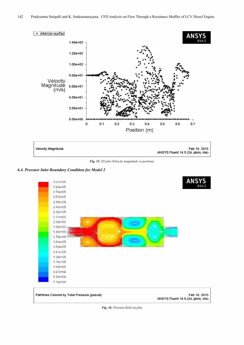
Fig. 15. XY plot (Velocity magnitude vs position).
6.4. Pressure Inlet Boundary Condition for Model 2
Fig. 16. Pressure field cut plot.

International Journal of Science, Technology and Society 2015; 3(4): 132-145 143
Fig. 17. Velocity field cut plot.
XY PLOTS
Fig. 18. XY plot (Total pressure vs position).

144 Pradyumna Saripalli and K. Sankaranarayana: CFD Analysis on Flow Through a Resistance Muffler of LCV Diesel Engine
Fig. 19. XY plot (Velocity magnitude vs position).
7. Conclusion
In this work two different models of a muffler have been designed for the engine output of an LCV diesel engine and the flow has been simulated using ANSYS FLUENT. The flow characteristics obtained through the simulation were promising.
On comparing the results and performances of the two models, we observe that though both the models have same similar design parameters, the second model was more effective in reducing the exhaust pressure than the second one because of its internal baffle arrangement.
1. Maximum velocity in model 1 for velocity inlet boundary condition is 133m/s
2. Maximum velocity in model 2 for velocity inlet boundary condition is 176m/s
3. Exhaust pressure reduction in model 1 is 53.82% 4. Exhaust pressure reduction in model 2 is 57.14% The reduction in pressure of exhaust in model 1 is 53.82 %
whereas the reduction in exhaust pressure in model 2 is 57.14 %. Hence we conclude that model 2 is more efficient in reducing the exhaust pressure when compared to model 1.
Future Scope
This work deals with the flow analysis of an automobile muffler which has a circular shell. Further experimentation can be done by incorporating an elliptical shell and subsequently the length of the muffler can be reduced with
similar performance or even an enhanced behaviour. Along with the changes in the shape of the shell and the
length of the muffler, the experimentation can be further implemented with changes in the following:
1. Boundary condition 2. Implemented solver 3. Can get in porosity (catalytic converter)
References
[1] Erdem Özdemir, Rifat Yılmaz, Zeynep Parlar, Şengül Ar, AN ANALYSIS OF GEOMETRIC PARAMETERS’ EFFECTS ON FLOW CHARACTERISTIC OF A REACTIVE MUFFLER, 17th International Research/Expert Conference ”Trends in the Development of Machinery and Associated Technology” TMT 2013, Istanbul, Turkey, 10-11 September 2013.
[2] Sileshi Kore, Abudlkadir Aman and Eddesa Direbsa, PERFORMANCE EVALUATION OF A REACTIVE MUFFLER USING CFD, Journal of EEA, Vol. 28, 2011.
[3] D. Tutunea, M.X. Calbureanu and M. Lungu, The computational fluid dynamics (CFD) study of fluid dynamics performances of a resistance muffler, INTERNATIONAL JOURNAL OF MECHANICS Issue 4, Volume 7, 2013.
[4] Prof. Amar Pandhare, Ayush Lal, Pratik Vanarse, Nikhil Jadhav, Kaushik Yemul, CFD Analysis of Flow through Muffler to Select Optimum Muffler Model for Ci Engine, International Journal of Latest Trends in Engineering and Technology (IJLTET),volume 4, issue 1, May 2014.
International Journal of Science, Technology and Society 2015; 3(4): 132-145 145
[5] Shital Shah, Saisankaranarayana K, Kalyankumar S. Hatti, Prof. D.G. Thombare, A Practical Approach towards Muffler Design, Development and Prototype Validation, SAE Paper 2010.
[6] Mr. Jigar H. Chaudhri, Prof. Bharat S. Patel, Prof. Satis A. Shah, Muffler Design for Automotive Exhaust Noise Attenuation - A Review, International Journal of Engineering Research and Applications, ISSN : 2248-9622, Vol. 4, Issue 1( Version 2), January 2014, pp.220-223
[7] Yunshi Yao, Shaodong Wei, Jinpeng Zhao, Shibin Chen, Zhongxu Feng, Jinxi Yue, Experiment and CFD Analysis of Reactive Muffler, Research Journal of Applied Sciences, Vol. 6 , (17): 3282-3288, September 2013.
[8] Rahul D. Nazirkar, S.R.Meshram, Amol D. Namdas, Suraj U. Navagire, Sumit S. Devarshi, DESIGN & OPTIMIZATION OF EXHAUST MUFFLER & DESIGN VALIDATION, Proceedings of 10th IRF International Conference,
[9] A.K.M. Mohiuddin, Ataur Rahman and Yazid Bin Gazali, SIMULATION AND EXPERIMENTAL INVESTIGATION OF MUFFLER PERFORMANCE, International Journal of Mechanical and Materials Engineering (IJMME), vol 2, 2007.
[10] M. Rajasekhar Reddy, Dr K. Madhava Reddy, Design And Optimization Of Exhaust Muffler In Automobiles, International Journal Of Engineering Research and Applications, ISSN: 2248-9622, Vol. 2, Issue 5, September- October 2012, pp.395-398.
[11] Vinod Sherekar and P. R. Dhamangaonkar “Design Principles for an Automotive Muffler” Volume 9, Number 4 (2014).
[12] Mrs.Varsha Chitale-Patil, Mr.Amol R.Patil, Prof.R.B.Patil “Design Analysis and Performance Evaluation of Reactive Silencer by SYSNOISE “Volume 3, India April 2014.
[13] Sunil, Dr Suresh P.M, Experimental Modal Analysis of Automotive Exhaust Muffler Using Fem and FFT Analyser, International Journal of Recent Development in Engineering and Technology( IJRDET).
[14] Sudarshan Dilip Pangavhane,Amol Bhimrao Ubale,Vikram A Tandon,Dilip R Pangavhane “Experimental and CFD Analysis of a Perforated Inner Pipe Muffler for the Prediction of Backpressure” Vol 5 No 5 Oct-Nov 2013.
[15] Mr. K.S. Tanpure, Dr. S.S. Kore “VIBRATIONAL ANALYSIS OF GENSET SILENCER USING FEA & FFT ANALYZER” Tanpure et al., 1(1): June, 2014.
[16] J.Kingston Barnabas, R.Ayyappan , M.R.Devaraj “ DESIGN AND FABRICATION OF EXHAUST SILENCER FOR CONSTRUCTION EQUIPMENT “ 2013 .
[17] OVIDIU VASILE, KOLUMBAN VLADIMIR “Reactive Silencer Modeling by Transfer Matrix Method and Experimental Study “Romania, June 24-26, 2008.
[18] Nitin S Chavan, Dr. S. B. Wadkar “Design and Performance Measurement of Compressor Exhaust Silencer By CFD” volume 2 September 2013.
[19] Shahid Nadeem, K.S.Shashishekar” DESIGN OPTIMIZATION OF INDUSTRIAL STEAM VENT SILENCER FOR NOISE REDUCTION CFD SIMULATION “volume 4, july-august 2013.
[20] Nicolae ENESCU, Ioan MAGHETI, Craita Daniela CARP-CIOCARDIA “Acoustical Silencers (Mufflers)” vol VII issue 1/2010.