cfd and aeroelastic analysis of the mexico wind … and aeroelastic analysis of the mexico wind...
TRANSCRIPT

CFD and Aeroelastic Analysis of the MEXICO Wind Turbine
PhD Student: Marina Carrión
Supervisors: Prof. G. Barakos, Drs R. Steijl and M. Woodgate
CFD Laboratory, School of Engineering, University of Liverpool www.liv.ac.uk/engdept
- Torque 2012 -

OUTLINE
Introduction
Numerical method
Overview of HMB
Aeroelastic method
Grid generation
Computations
Results
Aeroelastic effects
Low-Mach effects
Conclusions
- Torque 2012 -
H. Snel, J.G. Schepers and B. Montgomerie, The MEXICO project (Model Experiments in Controlled Conditions): The database and first results of data processing and interpretation.

INTRODUCTION
Publications on MEXICO wind turbine
Solvers
CFD incompressible
CFD compressible
Engineering models
Data
Pressure
PIV
Both
To date, no perfect matching with experiments:
Over-prediction at inboard sections.
Uncertainty at mid-span.
Wind tunnel effects seem to be negligible*.
Aeroelastic effects not studied yet.
Compressible solvers typically involve preconditioning and low-Mach effects haven’t been published.
- Torque 2012 -
*W.Z. Shen, and W.J. Zhu, and J.N. Sorensen, Actuator Line/Navier-Stokes Computations for the MEXICO Rotor: Comparison with Detailed Measurements, Wind Energy, DOI: 10.002/we.510, 2011.

Helicopter Multi-Block (HMB) SOLVER
Reynolds-averaged Navier-Stokes equations (RANS/URANS/DES).
Parallel distributed memory machines.
Multi-block structured grids.
Cell-centred Finite Volume Methods (FVM) for spatial discretization.
Osher’s and Roe’s schemes for convective terms discretization.
Monotone Upstream-centred Scheme for Conservative Laws (MUSCL) interpolation to provide 3rd order accuracy.
Van Albada flux limiter to avoid spurious oscillation across shocks.
Implicit time integration.
Uses axial flight to model a rotor, assuming periodicity in space and time.
Validated for several fundamental flows apart from rotors.
- Torque 2012 -

STRUCTURAL ANALYSIS METHOD Static non-linear analysis with NASTRAN (SOL 106)
Material properties keep the analysis in the linear region.
Beam model: analytical solution and very little data required.
- Torque 2012 -
Fluid grid (160 cells)
Structural grid (20 elements)
PBEAM RBAR
• Young’s modulus (E)
• Sectional area (A)
• Chord-wise area moment of inertia (I1)
• Flap-wise area moment of inertia (I2)
• Crossed area moment of inertia (I12)
• Linear mass distribution (LMD)
Available structural properties*
*A. Rosen, A. Wolf, D. Ben-Shmuel and G. Part I. The MEXICO Project Wind Turbine Model, TAE No. 985, Technion Research and development Foundation, August 2011.
*A. Rosen, A. Wolf, D. Ben-Shmuel and G. Omri, Part II. The MEXICO Project Wind Turbine Model, TAE No. 986, Technion Research and Development Foundation, August 2011.

AEROELASTIC COUPLING METHOD Start of
simulation
Compute the fluid
Extract blade loading
Compute the static
deflections
Deflections converged?
Deform the fluid grid
Three main steps for the coupling method*:
Transfer of fluid loads to the structural model.
Computation of the deformed blade shape.
Transfer of the blade structural deformation back to the fluid grid.
Fluid mesh deformation**:
Constant Volume Tetrahedron (CVT) interpolates from the fluid grid to the structural grid.
Spring Analogy Method (SAM) moves the block vertices.
Trans-Finite Interpolation (TFI) regenerates the entire grid.
no End of
simulation
- Torque 2012 -
*F. Dehaeze and G.N. Barakos, Hovering Rotor Computations Using an Aeroelastic Blade Model. October 2011.
**F. Dehaeze and G.N. Barakos, Mesh Deformation Method, AIAA J. of Aircraft, Vol 49, Issue 1 January 2012).

GRID GENERATION
C-topology: Orthogonality for good boundary layer resolution.
Periodic Planes*: Periodicity (in space and time) of the problem.
Sliding Planes**: Control of the wake resolution, change of topology mapping.
- Torque 2012 -
*R. Steijl, G.N. Barakos and K. Badcock, A Framework for CFD Analysis of Helicopter Rotors in Hover and Forward Flight, International Journal for Numerical Methods in Fluids, 51(8), 819-847, July 2006. **R. Steijl and G.N. Barakos, Sliding Mesh Algorithm for CFD Analysis of Helicopter Rotor-Fuselage Aerodynamics, International Journal for Numerical Methods in Fluids, 58(5), 527-549, October 2008.

SUMMARY OF COMPUTATIONS
Run Grid Size
Vwind
(m/s) Vtip
(m/s) Re
Aeroel. L.M.
I 2.6 M
15 100 1.65·106 II x
III 10 M
IV x
Aeroel.: Aeroelasticity, L.M.: Low-Mach scheme
Steady-state computations.
Pitch angle (at the tip) of -2.3 degrees (away from the wind).
Reynolds based on the chord at the blade’s root and tip speed.
Loads convergence obtained after 30,000 iterations .
Aeroelastics: 3 cycles for convergence (less than 20,000 iterations in each).
- Torque 2012 -

RESULTS. AEROELASTICITY (I) Torsional stiffness
- Torque 2012 -
Definition 1: minimum value between flap-wise and chord-wise inertias min(Ii,j)
Definition 2: average value between flap-wise and chord-wise inertias avg(Ii,j)
Bending Torsion

RESULTS. AEROELASTICITY (II)
Effective angle of attack
- Torque 2012 -
(-): away from the wind
(+): towards the wind
α: incidence angle
ε: twist
Effective incidence angle

RESULTS. AEROELASTICITY (II)
- Torque 2012 -
(-): away from the wind
(+): towards the wind
α: incidence angle
ε: twist
φ: pitch
Effective incidence angle

RESULTS. AEROELASTICITY (II)
- Torque 2012 -
(-): away from the wind
(+): towards the wind
α: incidence angle
ε: twist
φ: pitch
θ: torsional deflection
Effective incidence angle

RESULTS. AEROELASTICITY (II)
- Torque 2012 -
(-): away from the wind
(+): towards the wind
α: incidence angle
ε: twist
φ: pitch
θ: torsional deflection
Effective incidence angle

RESULTS. AEROELASTICITY (III)
60% R 92% R
Pressure coefficient (Cp) at three blade stations
- Torque 2012 -
35% R

RESULTS. LOW-MACH EFFECTS (I) Low-Mach Roe scheme*
*F. Rieper, A Low-Mach Number Fix for Roe’s Approximate Riemann Solver, J. Comput. Phys. 230 (2011) 5263–5287.
S809 aerofoil at α=2.1 deg. and M=0.01
- Torque 2012 -
where,
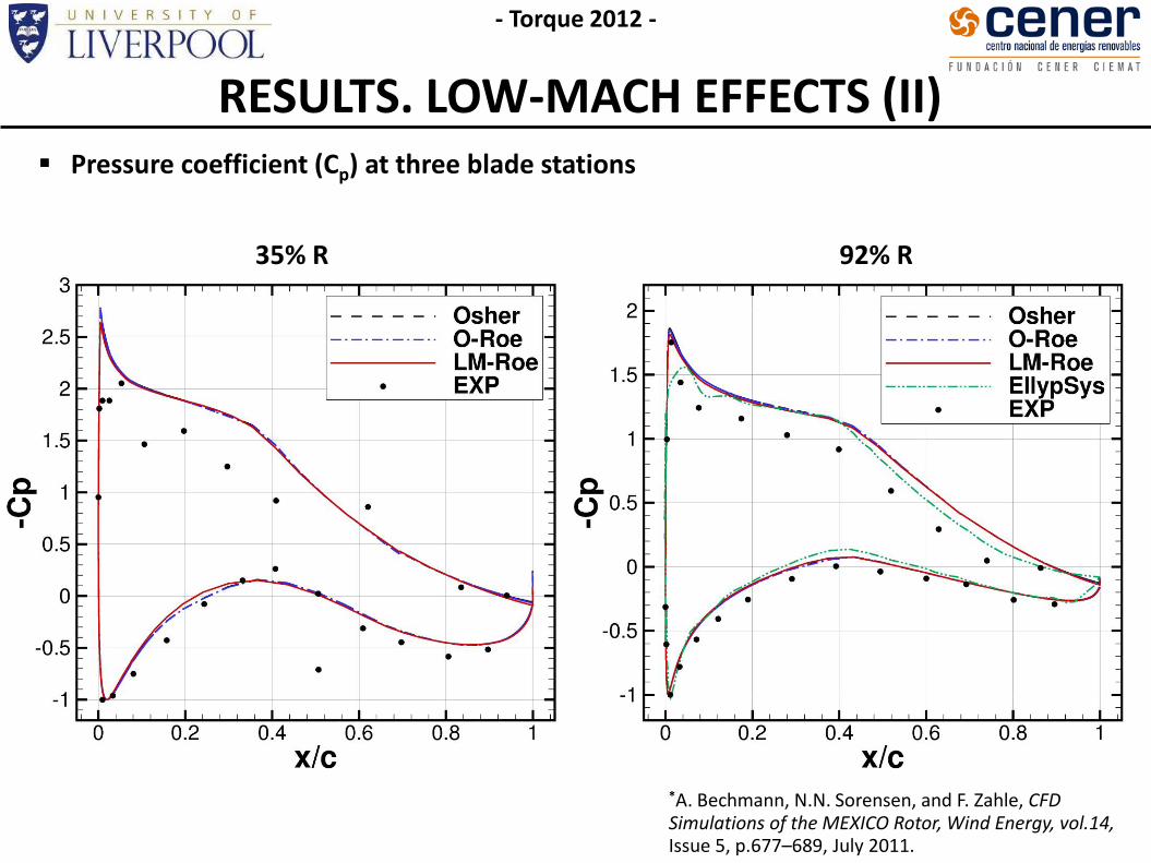
RESULTS. LOW-MACH EFFECTS (II)
35% R 92% R
- Torque 2012 -
*A. Bechmann, N.N. Sorensen, and F. Zahle, CFD Simulations of the MEXICO Rotor, Wind Energy, vol.14, Issue 5, p.677–689, July 2011.
Pressure coefficient (Cp) at three blade stations

RESULTS. LOW-MACH EFFECTS (III)
- Torque 2012 -
Contours of axial velocity component (u)
Osher CFD results.
PIV windows from experiments.
Blade azimuth at 270 deg.

RESULTS. LOW-MACH EFFECTS (IV)
- Torque 2012 -
Contours of axial velocity component (u)
LM-Roe CFD results.
PIV windows from experiments.
Blade azimuth at 270 deg.
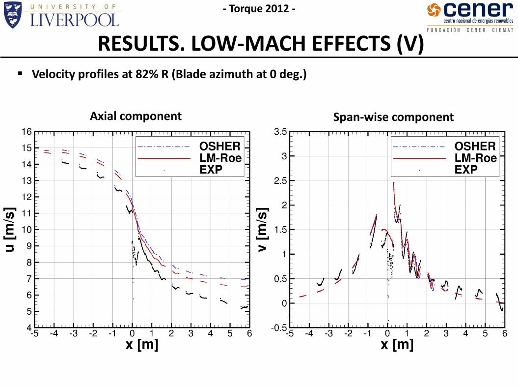
RESULTS. LOW-MACH EFFECTS (V) Velocity profiles at 82% R (Blade azimuth at 0 deg.)
- Torque 2012 -
Axial component Span-wise component

RESULTS. LOW-MACH EFFECTS (VI) Estimation of the vortex position and radius.
Extracted visually, from the experimental and CFD results.
Position Radius
- Torque 2012 -

CONCLUSIONS & FUTURE WORK Aeroelasticity
And attempt was made to quantify the aeroelastic effects on the MEXICO wind turbine.
Coupled method NASTRAN/HMB for the analysis.
Uncertainty on the torsional stiffness. The outboard stations are influenced, while the discrepancies inboards are the same as
reported in the literature. Aeroelastic effects were expected to be small.
- Torque 2012 -
Low-Mach effects
Compressible CFD solvers can account for low-Mach effects.
A variant of Roe was implemented, with an efficient implicit formulation.
For aerofoils, the effect is strong.
At 15m/s MEXICO blade, small effects were expected due to the high tip speed.
On the wake, the low-Mach scheme seems to capture better the position of the vortices (less dissipative nature).
Future Work
Need to identify the exact structural properties for the MEXICO blade.
Different wind speeds were already computed, however, the study will be extended.
Low-Mach effects could be perhaps present in the NREL wind turbine, which will be studied.

- Torque 2012 -