cfd modeling of flue gas cooler of oxy fired bubbling ... · the maximum air flow rate used for...
TRANSCRIPT

Abstract—In many industrial processes hot gas is cooled
down before it has been sent to atmosphere. The flue gas is a gas
mixture that mainly consists of oxygen, carbon dioxide, water
vapor and nitrogen. Additional it may contain sulphur dioxide,
nitrogen dio oxide and other marginal species. It usually also
contains dust and ashes. While the oxygen content is very much
lowered compared to that of ambient air, the content of carbon
dioxide can reach a volume fraction of up to twenty five percent.
Especially at the modern waste incineration plants the content
of water vapor can go up to a few percent.
In this work computational fluid dynamic model is formed
for flue gas cooler that are attached in series for 20 kW Oxy
fired Bubbling fluidized bed Combustor Using Coal and
Biomass. The model is based on the Lagraingian approach and
Discrete Particle Model. The model is solved using commercial
Software Ansys Fluent. The geometrical domain is formed in
Solid Works. The simulations were performed in Ansys Fluent
commercial software. The maximum air flow rate used for this
simulation is 80 kg per hour. The flue gas enters on the side of
gas cooler and few particles are entrained in gas cooler. The flue
gas is the sucked by ID fan. The flue gas is cooled with the help
of 0.5 HP water circulation pump. The pump circulates the
water through 0.5 inch pipe line. In order to cool the flue gas
down cold water a flow rate of 10-12 litre per minute and
temperature of 293 K is supplied. The velocity, temperature and
pressure contours are plotted. The results are also calculated
for different types of fuels. The various types of biomass and
coal are used in fluidized bed. This leads to variation of ash
particles size in flue gas. The particle size in fuel causes the
variation in size of ash in flue gas which in turn affects the
performance of flue gas cooler. The effect of variation in size of
particles on exit flue gas temperature is also investigated.
Index Terms—Flue gas cooler, discrete particle model, flow
rate, lagrangian approach.
I. INTRODUCTION
The problem of designing flue gas cooler is to withstand
the highly abrasive nature of flue gas leaving the process
chamber, as well as the high temperature. The high degree of
gas cleansing before it leaves process equipment demanded
today by many of our communities.
Due to high ash content in coal used in fluidized bed units
it becomes necessary to add a gas cooling device before the
gas exit to atmosphere along with the multi-cyclone collector.
This is done to assure that the exiting flue gases are within
the temperature range of 300 to 450 K, with no possibility of
even flashes of higher temperatures. The exit temperature of
flue gas depends upon the materials of pipe, chamber, and
supply of water in the flue gas cooler.
Manuscript received June 14, 2016; revised November 4, 2016.
Ravi Inder Singh is with Birla Institute of Technology and Science-Pilani,
Pilani Campus Jhunjhunu, Rajasthan, 333031, India, 00911596515096
(e-mail: [email protected]).
Computational Fluid Dynamics (CFD) is a tool
increasingly used for the solution of flow related engineering
problems. The applications have a broad variety: Simulations
in automobile and aerospace industry, biomedical industry,
electronics cooling, chemical engineering, turbo machinery,
combustion, heat and power generation as well as heat and
cold pipes are possible applications.
In the field of combustion CFD is being increasingly used
for the optimization of gas combustors and pulverized coal
furnaces and numerous types of heat exchangers. The CFD
routines developed for biomass based furnaces, heat
exchangers and boilers are successfully applied in various
cases regarding furnace and boiler development as well as
regarding the optimization of existing equipments from
small-scale to medium and large scale furnaces and boilers.
The development and optimization of biomass grate furnaces
via CFD analysis leads to a considerable reduction of
investment and operating costs by a heat exchanger design,
by an increased availability of the heat exchanger, by reduced
fouling as well as by reduced flue gas fluxes in the heat
exchanger.
Furthermore, CFD analysis also helps to avoid velocity
and temperature peaks in certain heat exchanger which are of
special relevance regarding material stress and deposit
formation. For high ash fuels additional measures, like ash
deposit formation can be investigated with CFD simulation.
In addition, the influence of particle laden flue gas flow on
material stress caused by erosion can also be evaluated using
"particle tracking calculations" and considered by material
selection or prevented by appropriate modifications of heat
exchanger. Actual residence times of flue gas, velocity and
temperature are interesting results in flue gas cooler. Finally,
CFD simulations lead to an improved understanding of the
fundamental physical and chemical processes in the flue gas
cooler and, therefore, to a considerably improved design.
In this work computational fluid dynamic model is formed
for flue gas cooler that are attached in series for 20 kW Oxy
fired Bubbling fluidized bed Combustor using coal and
biomass. The model is based on the Lagraingian approach
and Discrete Particle Model. The model is solved using
commercial Software Ansys Fluent. The results are validated
with measurements from experimental setup.
II. LITERATURE REVIEW
Heat exchangers are very important part of energy
recovery system of waste to energy plants. Selection of
suitable types of heat exchangers represents primary
importance in design of these systems. it is necessary to
perform the design of heat exchangers with maximum degree
of compactness in relation to process parameters like
CFD Modeling of Flue Gas Cooler of Oxy Fired Bubbling
Fluidized Bed Combustor Using Coal and Biomass
Ravi Inder Singh
International Journal of Environmental Science and Development, Vol. 8, No. 4, April 2017
236doi: 10.18178/ijesd.2017.8.4.954

temperature, composition of process fluids, proximity to
fouling and potential operational problems. Although
numerous research papers found on heat exchangers but very
few relevant papers are found as flue gas cooling is not
required for many of industrial processes.
Viggo [1] discussed the effects of flue gas cooling in
power plants. Simon (1995) discussed that the nuclear power
station could not be put into operation and decided to erect a
thermal power station. They studied about the flue gas
desulfurization system. They found that public acceptance
could not be reached without sufficient flue gas cleaning
systems.
Kvamsdal [2] discussed the results of an activity
performed in the ongoing EU project, CESAR. In this project
five different baseline power-plants are considered. These
consist of two lignite- and two bituminous-coal fired plants
while the fifth is fuelled by natural gas. Part of the design
work relates to identifying the benefits attainable through
appropriate integration of flue-gas cooling to these baseline
power-plants. The reductions in capturing of flue gas are
basically due to the inclusion of pre-cooling. However, a
positive effect of inter-cooling was also found for all the coal
cases, while a negative cost effect was found for the natural
gas case. For piperazine as solvent the positive effect of
cooling was much more pronounced than for MEA and
especially the effect of inter-cooling.
Gao and Sun [3] studied the exhaust flue gas cooler in a
300 mw oxy-coal fired boiler. The simulation model of the
cooler was established by the method of lumped parameter.
The change rule of the exhaust flue gas cooler parameters and
the flue gas thermal physical property parameters were
analyzed by the disturbance of the coal feeder speed. It is
found that, the simulation model of exhaust flue gas cooler
was established based on the conservation laws of mass,
momemtum and energy. The simulation experiment results
show that the change rules of main operational parameters
and the flue gas thermal physical property parameters in the
exhaust flue gas cooler can be reasonably presented by the
model with the speed disturbance of coal feeder, which can
be the reference for the design and the operation control of
the flue gas coolers.
Nipun [4] discussed the design and performance analyses
of condensing heat exchangers for recovering water and
waste heat from flue gas. There has been an increasing
interest in new technologies to improve the efficiency of coal
based thermal power plants and to reduce the consumption of
cooling water for cooling towers. This report discusses the
opportunities of recovering heat and water from flue gas
using condensing heat exchangers. The impact on water
condensation efficiency, total heat transfer and total annual
cost were analyzed for five different arrangements. The
impact of heat exchanger design parameters such as heat
exchanger tube diameter and tube transverse pitch was
analyzed. Additionally, the prospects of pre cooling the flue
gas using water spray and its impact on performance of heat
exchanger was also studied.
Samer [5] investigated direct contact condensation for wet
flue-gas waste heat recovery using organic rankine cycle.
Low-temperature flue gases exiting industrial processes
could be recovered for electricity generation and constitute
an effective mean to reduce primary energy consumption and
carbon dioxide emissions. in the wet flue gases, substantial
heat can be recovered if water vapor contained in the gases is
condensed. technical options include indirect contact water
vapor condensation recovery, where heat is transferred
between the two fluids (typically flue gases and working fluid)
using an intervening wall (typically fin-and-tube heat
exchanger) and direct contact water vapor condensation
recovery, which involves direct mixing between flue gases
and cooling fluid (typically water) through a condensing unit.
Precise Literature on flue gas cooling has not been found.
Detailed literature is proprietary of companies.
III. DETAILS OF EXPERIMENTAL APPARATUS
The experimental setup is shown in Fig. 1. The details of
this setup is as below. This length of fluidized bed unit is 1.8
m. This is square bubbling fluidized bed combusor made
from DST, New Delhi India Grant. This is followed by two
cyclones, induced fan, flue gas cooler and stack. The two
cylones are used because this unit is designed for mainly high
ash coal and biomass. The oxygen can be supplied from
bottom and as well from side. But this system works well for
other waste also. The net thermal capacity of this system is
below 20 kW. The maximum amonut of fuel supplied that
can be supplied to this unit is 15 kg/hr. The test rig is used for
experimental validation. Fig. 2 shows the description of flue
gas cooler. Fig. 3 shows the actual picture of flue gas cooler.
The dimensions and other parameters required for study are
given in Table I.
Fig. 1. Experimental setup.
Fig. 2. Description of flue gas cooler.
The results are discussed in results and discussion content.
The ports S is used for mesurement of gas concentration. The
flue gas is passed through twin cylones. The eighty
percentage of ash is entrained through first cylone and
Flue Gas
Inlet
Flue Gas
Exit
Water Inlet Water
Outlet
Flue Gas Recycle
Thermocouple
International Journal of Environmental Science and Development, Vol. 8, No. 4, April 2017
237

remaining twenty percentage in second cylone. Fig. 2 also
shows the thermocouples which are used for measurment of
temeperature. The other ports are also used for measurement
of velocities. The velocities of flue gas cooler are measured
using Testo 350 XL professional which is purchased through
DST, New Delhi, India Grant.
Fig. 3. Actual picture of flue gas cooler of experimental setup.
TABLE I: DIMENSION OF FLUE GAS COOLER AND OTHER PARAMETERS
Description Numeric
Value Units
Dimensions(l*b*h) 0.5*0.3*0.4 m3
Water Flow Rate 10-15 Litre per minute
(lpm)
Inlet water temperature 303 K
Outlet water temperature 313 K
Inlet flue gas temperature 673-523 K
Outlet flue gas temperature 423-523 K
Atmospheric pressure 1 bar
Water Pump Capacity 0.5
HP
(Horse
power)
Pipe Diameter 0.5 inch
Pipe Material Copper
IV. CFD MODELLING
The conservation equations involved in this study are given
as follows. The brief description is as follows.
Mass Conservation equation for gas phase
𝜕
𝜕𝑡(𝑓𝑔𝜌𝑔) + ∇. 𝑓𝑔𝜌𝑔𝑣𝑔 = 0 (1)
Mass conservation for solid phase
𝜕
𝜕𝑡(𝑓𝑠𝜌𝑠) + ∇. 𝑓𝑠𝜌𝑠𝑣𝑠 = 0 (2)
Momentum equation for gas phase
𝜕
𝜕𝑡(𝑓𝑔𝜌𝑔𝑣𝑔) + ∇. 𝑓𝑔𝜌𝑔𝑣𝑔𝑣𝑔 = - 𝑓𝑔∇.𝑇𝑔
𝑒𝑓+ 𝑓𝑔𝜌𝑔𝑔 - ∇𝑝
+ Fres (3)
Momentum conservation in solid phase:
𝜕
𝜕𝑡(𝑓𝑠𝜌𝑠𝑣𝑠) + ∇. 𝑓𝑠𝜌𝑠𝑣𝑠𝑣𝑠 = 𝑓𝑠𝜌𝑠𝑔 - Fres (4)
Energy conservation in the gas phase:
𝜕
𝜕𝑡(𝑓𝑔𝜌𝑔𝑣𝑔𝐶𝑝𝑔𝑇𝑔) + ∇. 𝑓𝑔𝜌𝑔𝑣𝑔𝐶𝑝𝑔𝑇𝑔 = - 𝑓𝑔∇. 𝑞𝑔
𝑒𝑓+ 𝑓𝑔𝑞𝑔𝑠 (5)
Energy conservation in the solid phase:
𝜕
𝜕𝑡(𝑓𝑠𝜌𝑠𝑣𝑠𝐶𝑝𝑠𝑇𝑠) + ∇. 𝑓𝑠𝜌𝑠𝑣𝑠𝐶𝑝𝑠𝑇𝑠 = 𝑓𝑠𝑞𝑔𝑠 (6)
Constitutive equations:
𝑇𝑔𝑒𝑓
= -2𝜇𝑒𝑓𝐷𝑔 (7)
The deformation rate is given as:
𝐷𝑔 = ½[∇𝑣𝑔 + ∇𝑣𝑔𝑇] (8)
𝜇𝑒𝑓 = 𝜇𝑔 +𝜇(𝑡) (9)
A correlation for turbulent viscosity is given as follows:
𝜇(𝑡)=𝜌𝑔𝑘𝑔
1/2 Dh /10 (10)
For particles in flue gas discrete particle model is used. The
reasons for choosing standard Lagrangian Model for
dispersed phase is due to limited computational power
available. The particle trajectory can be predicted for the ix (i
=1, 2, 3 for three dimensions) direction in Cartesian
coordinates by [6]:
2
,2
( )( )
i
piD i p i i x
p
d xF v v gx F
dt
(11)
where Fxi is the additional force, ,( )D i p iF v v is the drag force
per unit particle mass and
2
Re18
24
DD
p p
CF
d
(12)
The details of CFD model is given elsewhere in Ansys
Fluent User Guide [6]. The details of boundary conditions
and solution methodology can be referred from Table II.
TABLE II: BOUNDARY CONDITIONS AND OTHER SIMULATION DETAILS
Parameter Details
No. of Cells used 900218
Type of Cells Used Hexahedral and Triangular
Multiphase Model Eulerian Lagrangian
Fuel Feed rate 10-15 kg/hr
Oxygen Fed rate 10 Kg/hr
Amount Air Fed 40 kg/hr
Pressure Atmospheric
Convergence Criteria 0.0001
Pressure velocity
coupling
Phase coupled
SIMPLE
Air inlet velocity 2-8 m/s
Particles
Ash from biomass and
coal[Average particle size
of [0.1-0.45 mm]]
Under Relaxation
factors
Pressure: 0.1, Density: 1,
Body Forces: 1,
Momentum: 0.3, Energy:
0.5, DPM: 0.3
The numerical simulation was carried out at inlet air
velocity of 2 m/s and particle concentration diameter varies
from 0.1 to 0.45 mm at 623K. The boundary conditions are
chosen from experimental details as mentioned in Table II.
International Journal of Environmental Science and Development, Vol. 8, No. 4, April 2017
238

V. RESULTS AND DISCUSSION
The CFD model is solved using commercial Software
Ansys Fluent. The geometrical domain is formed in Solid
Works. The simulations were performed in Ansys Fluent
commercial software. The simulation was run on workstation,
T1700, xenon quad core processor, 3.7 mz, 32 GB Ram. The
simulation is run for approximately six hours for 5000
iterations for each individual result. The mesh used for CFD
simulation is shown in Fig. 4. It consists of primarily
hexahedral and pyramid elements.
Fig. 4. Mesh picture.
Fig. 5 shows the velocity profiles in flue gas cooler. The
velocity contours are formed through commercial software.
The velocity near the entry is higher and its decreases as it
contacts with walls of tubes and duct. The velocity is higher
at the exit pipe as shown in Fig. 5. It is higher because of fact
that cross-sectional area is decreasing at the exit. Fig. 6 shows
the velocity vectors in flue gas cooler. Fig. 6 also shows some
of reverse flow occurs near the walls of flue gas cooler. It
occurs because of continuously sucking the flue gas at high
velocity by exhaust fan and some abnormalities in flow due
to fouling. Due to fouling there is layer of deposition of ash
on pipes. This layer is of uneven thickness causing
abnormalities in flow.
Fig. 5. Iso contours of velocity magnitude in flue gas cooler.
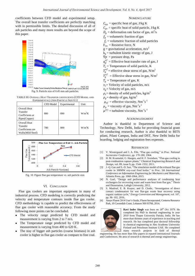
Fig. 7 shows the temperature contours in in flue gas cooler
Inside the cooler it varies from 400 to 523 K. At the exit the
temperature is higher. It is because of high velocity few ash
particles are carried along with flue gas and could not get
enough time for cooling. The temperature inside the copper
pipe is constant as cooling is done constant through
continuous supply of water 0.5 HP motor. Fig 8, 9 shows the
flow of ash particles inside flue gas coolers. As shown in Fig.
9 the heavier particle will stay inside cooler and are removed
through lower opening in cooler. Whereas lighter particles
are drifted towards exit. Due to space limitation only two
particles are shown. The average size of ash due to fine coal
is 0.1 mm and average size due to coarse biomass is 0.45 mm.
Due to size of ash the fouling conditions prevails in flue gas
cooler. Flue gas exit temperature versus ash particle size is
shown in fig. 10. Flue gas temperature increases by 60 K. It is
shown in Fig. 10. This is because increase in size of ash
causing fouling of heat exchanger tubes which in turns
decreases the effectiveness of flue gas cooler. These results
are also compared with respect to CFD model. Experimental
measurements were also taken and validated with CFD
model.
Fig. 6. Velocity vectors in flue gas coolers.
Fig. 7. Temperature contours in flue gas cooler.
Fig. 8. Particle size of 0.1 mm ash particles.
Table III shows the comparison of overall heat transfer
International Journal of Environmental Science and Development, Vol. 8, No. 4, April 2017
239
coefficients between CFD model and experimental setup.
The overall heat transfer coefficients are perfectly matching
with in permissible limits. The detailed discussion of all of
ash particles and many more results are beyond the scope of
this paper.
Fig. 9. Particle size of 0.45 mm ash particles.
TABLE III: OVERALL HEAT TRANSFER COEFFICIENTS (CFD MODEL AND
EXPERIMENTAL) {ASH PARTICLE SIZE 0.1}
CFD Model Experimental Unit
Overall Heat
Transfer
Coefficients at
Pipes(Copper)
880 890 W/m2K
Overall Heat
Transfer
Coefficients are
Walls(Mild Steel)
780 800 W/m2K
Fig. 10. Figure flue gas temperature vs. ash particle size.
VI. CONCLUSION
Flue gas coolers are important equipment in many of
industrial process. CFD modeling is correctly predicting the
velocity and temperature contours inside flue gas cooler.
CFD methodology is capable to predict the effectiveness of
flue gas cooler with reasonable accuracy. From the study
following more points can be concluded.
The velocity range predicted by CFD model and
measurement is varying from 2 to 7 m/s.
The Temperature range predicted by CFD model and
measurement is varying from 400 to 620 K.
The stay of bigger ash particles (coarse biomass) in ash
cooler is higher in flue gas cooler as compare to fine coal.
NOMENCLATURE
𝐶𝑝𝑔 = specific heat of gas, J/kg K
𝐶𝑝𝑠 = specific heat of solid particle, J/kg K
𝐷𝑔 = deformation rate factor of gas, m2/s
𝑓𝑔 = volumetric fraction of gas
𝑓𝑠 = volumetric fraction of solid particles
Fres = Resistive force, N
g = gravitational acceleration, m/s2
kg = turbulent kinetic energy of gas, J
∇𝑝 = pressure drop, Pa
𝑞𝑔𝑒𝑓
= Effective heat transfer rate of gas, J
𝑇𝑠 = Temperature of solid particle, K
𝑇𝑔𝑒𝑓
= effective shear stress of gas, N/m2
𝑇𝑔𝑒𝑓
= Effective shear stress in gas, N/m2
𝑇𝑔 = Temperature of gas, K
𝑣𝑠= Velocity of solid particles, m/s
𝑣𝑔= Velocity of gas, m/s
𝜌𝑠= density of solid particles, kg/m3
𝜌𝑔= density of gas, kg/m3
𝜇𝑒𝑓 = effective viscosity, Nm-1s-1
𝜇𝑔 = viscosity of gas, Nm-1s-1
𝜇(𝑡) = turbulent viscosity, Nm-1s-1
ACKNOWLEDGMENT
Author is thankful to Department of Science and
Technology, New Delhi, India for providing financial grant
for conducting research. Author is also thankful to BITS
pilani, Pilani Campus, India and DST, New Delhi India for
boarding, lodging and registration fees expenses.
REFERENCES
[1] V. Westergaard and J. A. Fife, “Flue gas cooling,” in Proc. National
Incinerator Conference, pp. 170-180, 1964.
[2] H. M. Kvamsdal, G. Haugen, and H. F. Svendsen, “Flue-gas cooling in
post-combustion capture plants,” Chemical Engineering Research and
Design, vol. 89, issue 9, pp. 1544–1552, 2011.
[3] J.-Q. Gao and S.-D. Sun, “The simulation model of the exhaust flue gas
cooler in 300MW oxy-coal fired boiler,” in Proc. 5th International
Conference on Information Engineering for Mechanics and Materials,
Atlantis Press, pp. 1060-1064, 2015. [4] N. Goel, “Design and performance analyses of condensing heat
exchangers for recovering water and waste heat from flue gas,” Thesis
and Dissertation, Lehigh University, 2012.
[5] S. Maalouf, E. B. Ksayer, and D. Clodic, “Investigation of direct
contact condensation for wet flue-gas waste heat recovery using
organic rankine cycle,” Energy Conversion and Management, vol. 107,
pp. 96–102, 2016. [6] Ansys Fluent 2014 User’s Guide, Fluent Incorporated, Centerra Resource
Park, 10 Cavendish Court, Lebanon NH 03766, 2014.
Ravi Inder Singh was born on 18th Oct 1979. He
completed his PhD in thermal engineering in year
2010 from Thapar University Patiala, India. He has
more than thirteen years of experience in teaching and
research. He has completed post doctoral fellowship
in chemical engineering in Abo Academy University
Finland and Petroleum Institute UAE. He completed
many research projects in field of thermal
engineering. He has more than fifty papers in reputed international Journals
and Conferences. He area of research is thermal and energy engineerings.
International Journal of Environmental Science and Development, Vol. 8, No. 4, April 2017
240