cfd modeling of pulp & paper kilnsbibeauel/research/papers/... · 2008-12-30 · cfd modeling...
TRANSCRIPT

www.amerflowtec.com
CFD MODELING OF PULP & CFD MODELING OF PULP &
PAPER KILNSPAPER KILNSE. Bibeau and K. AdaneE. Bibeau and K. Adane
2006 CFD SummitMay 22-24, 2006 - Monterey, CA

AFT BackgroundAFT BackgroundServices
Modeling CFD ServicesHelp clients for development of engineered systems and in users of equipment faced with complex problems
BenefitsEnhanced Engineering JudgementHardware design solutionsIntegration of CFD in design process

CFD in IndustryCFD in IndustryAdvantages
Technical risks reductionLessen project uncertaintyEnvironmental complianceDecrease energy costsImprove the commissioning phaseImprove equipment performanceEvaluate proposed changesCan evaluate “what if” scenarios

Lime KilnsLime Kilns

Key Issues Lime KilnsKey Issues Lime KilnsKiln efficiencyFuel substitutionBurner characteristicsFlame shape/positionOptimal swirl numberReduce energy costsEmissions: NOx, SOxRefractory life

Model PredictionsModel PredictionsEffect of burner and settingsFlame shapeHeat release profile to productHood shape and air ports influencePrimary/Secondary/Fuel ratio influenceGas species (H2, O2, N2, CO, CO2, H2O, CH4)Pollutant emissions (e.g. NOx)Oil or solid fuel (tires, coke, coal) combustion and droplet trajectoryMud, refractory, and shell temperatures

Lime KilnsLime KilnsBurner (combination)– atomizing oil + steam– coal and coke solid fuel – natural gas– non-condensable gases– alternative energy fuels (biogas, waste polymers)
Primary air– via burner and used for conveying solid fuel
Secondary air– induced air through various kiln air ports– air leakage from seal gap, camera ports, side hood port,
and back hood ports

Comprehensive Input Condition ModelComprehensive Input Condition Model
EXCEL
DATA INPUT ANDRITZ
CFD

Parametric Mesh Generation Using Parametric Mesh Generation Using Gambit for Gambit for ““what ifwhat if”” senriossenrios
/case 9: calcinations kiln Andritz. New SA and lance and 6 holesresetsolver select "FLUENT 5/6"
$imesh = 5$scale1 = 1.0$ilance = 1
default set "MESH.INTERVAL.SIZE" numeric 0.1
/kiln$l1 = 0.6096$l2 = $l1 + 0.3048$l3 = $l2 + 2.24$l4 = $l3 + (15.14 + 12.19)*$scale1$r4 = 3.708/2$r3 = 1.651$r2 = 1.588$r1 = 0.991$r0 = 0.750
/air seal$gap1 = 0.0127$gap3 = 0.0254
/grate$grate_xo = -0.333$grate_yo = 22*0.0254$grate_x = (2*12+2.5)*0.0254*0.80$grate_y = (3*12+4.5)*0.0254*0.80
/shell distance from hood$gap2 = $l3
volume create "kiln" height ($l1) radius1 ($rh-$gap1) radius3 $r1 offset ($l1/2) 0 0 xaxis frustumvolume create "k2" height ($l2-$l1) radius1 $r1 radius3 $r1 offset (($l2-$l1)/2+$l1) 0 0 xaxis frustumvolume create "k3" height ($l3-$l2) radius1 $r1 radius3 $r2 offset (($l3-$l2)/2+$l2) 0 0 xaxis frustumvolume create "k4" height ($l4-$l3) radius1 $r2 radius3 $r2 offset (($l4-$l3)/2+$l3) 0 0 xaxis frustumvolume unite volumes "kiln" "k2" "k3" "k4" volume create "shell" height ($l4-$gap2) radius1 $r4 radius3 $r4 offset (($l4-$gap2)/2+$gap2) 0 0 xaxis frustumvolume split "shell" volumes "kiln" connected bientityvolume unite volumes "kiln" ("volume."+ntos(LASTID(4)-1))
face create "ring1" width (5) height (5) offset (0) (5/2) (0) yzplane rectangleface split "face.34" connected face "ring1"face create "ring2" width (5) height (5) offset (-$gap3) (0) (0) yzplane rectangleface split "face.31" connected face "ring2"
IF COND ($imesh .gt. 1)$l2plus = $l2volume create "mud" width ($l4-$l2plus) depth 5 height 2 offset (($l4-
$l2plus)/2+$l2plus) 0 (-2/2-$h_mud) brickvolume move "mud" dangle (-90.0-$angle) vector 1 0 0 origin 0 0 0
connectedvolume subtract "kiln" volumes "mud" keeptoolvolume subtract "shell" volumes "mud"
volume create "burner" height ($lb+0.5) radius1 $rb11 radius3 $rb11 offset ($lb/2 -$lh - 0.5/2) 0 0 xaxis frustum
volume move offset (0.0+$lh) 0 0

Kiln Geometry ExampleKiln Geometry ExampleTop holes 5 and 6
Lower leakage ring
Upper leakage ring
Grate
Middle holes 4 and 5 with burner leakage
Dam area with throat sectionBurner & Lance
Kiln with bricks
Lime bed

Unstructured body-fitted coordinates with both hexa and tetra elements (GAMBIT)
Numerical DescriptionsNumerical Descriptions
Sample Mesh of the Kiln

Fully three-dimensional Reynolds-averaged transport equations of mass, momentum energy, and chemical speciesTwo-equation k-e turbulence modelDiffusion equation for 3D radiation heat transferRefractory wall modelSeparate sub-models for drying, devolatilization, and char combustion for the cokeNOx formation model
Numerical DescriptionsNumerical Descriptions

CmHn+ (m + 0.25n)O2= mCO2 + 0.5n H2O
CO+0.5O2 = CO2
H2+0.5O2 = H2O
Arrhenius-reactions kineticsGas combustion–controlled by turbulent diffusion (Magnussen eddy-dissipation Model)
Swirl number
Numerical DescriptionsNumerical Descriptions
eqCokeAirInnerNGOuterNGimaryAirOuter
gAirimarySwirlInner
DvmvmvmvmRvm
])()()()[()45sin()(
Pr
Pr
&&&&
&
+++

Operational ParametersOperational ParametersHeat input via combination of fuels– 20 to 40 MW typical range– depends on market price and availability of alternative
fuelsFuels– gas, oil, coke, biogas, polymers
Port openings– Various strategies to influence flame/hood interactions
Decrease thermal NOx formationPrevent high temperatures that contribute to premature brick failuresNCG burning: interaction with main flameBurner tilt

Simulation ResultsSimulation Results

Streamlines
OIL & COKE
Oil/CokeOil/Coke
Oil/Coke

Comparison to 1Comparison to 1--D ModelsD Models
gMass fraction of c19h30 Mass fraction coke volMass fraction of o2 Mass fraction of CO Mass fraction of co2 Mass fraction of H2Mass fraction of CH4Mass fraction of n2 Mass fraction of C(s)Mass fraction of S(s)Mass fraction of h2o Mass fraction of so2
CFDAveraged
Values
Overall mass balance 1-D
models (IDEAS)

Temperature Velocity vectors
NGNG/Coke/Coke
NG & COKENG & COKE
NG/NG/CokeCoke

Effect of CoEffect of Co--firingfiringNG/Coke
NG/Coke
Temperature (K)Lance

Coke SubstitutionCoke Substitution
NG/Coke
NG/Coke
Temperature (K)

Oil/NG
Oil/NG
Oil/NG
OIL & NG
NONOxx

Emissions
Consultants/Andritz
Permits
CFD
Kiln
Emission Data
Regulation

OIL & COKE
SOSO22/O/O22
Oil/Coke Oil/Coke
Oil/Coke
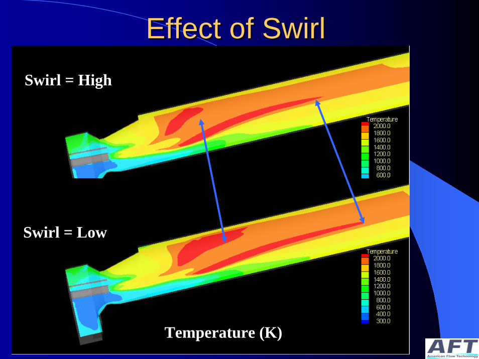
Effect of SwirlEffect of SwirlSwirl = High
Swirl = Low
Temperature (K)

Effect of SwirlEffect of SwirlSwirl = High Swirl = Low
Temperature (K)

Effect of Swirl of BurnerEffect of Swirl of Burner
Swirl = High
Swirl = Low
Velocity Magnitude (m/s)

ConclusionConclusionUse CFD to support emission permit processUse CFD to optimised burner chamber interactions Model NOx and SO2 formation in kilns to aid burner designSwirl number is important for both burner design and operations.

AcknowledgmentAcknowledgment
Andritz – Burner studies and designsUniversity of Manitoba– CFD simulations of alternative
energy
www.amerflowtec.com