cfm modular ethernet idus.tech-description
TRANSCRIPT

SAF CFM Series
Modular Fast Ethernet Bridge
Indoor Unit Management System Technical Description and Configuration
Guide
Software Version 3.xx
© SAF Tehnika A/S 2005

Modular Fast Ethernet Bridge Management System Technical Description and Configuration Guide Rev. 1.5 © SAF Tehnika A/S 2005
2
Table of Contents
1 Overview.................................................................................................. 3 2 Fast Ethernet Bridge IDU Appearance...................................................... 5
2.1 Labeling.............................................................................................. 8 3 Interface modules.................................................................................... 9
3.1 V.35 Interface Module........................................................................... 9 3.1.1 V.35 Interface Module LEDs ............................................................. 9
3.2 E1 Interface Module ............................................................................10 3.3 10Base-T REB Interface Module.............................................................11
3.3.1 10Base-T REB Interface Module LEDs ...............................................11 3.4 2-port 100Base-T REB Interface Module .................................................12 3.5 V.35-G.704 Converter Module...............................................................13
3.5.1 V.35-G.704 Converter Module LEDs..................................................13 4 Management Interfaces ......................................................................... 14
4.1 Reading the LEDs................................................................................14 4.2 LCD/Keypad .......................................................................................14
4.2.1 “Status Display” Mode of the IDU LCD Management Interface ..............14 4.2.2 “Setup” Mode of the IDU LCD Management Interface ..........................16 4.2.3 Reset Functions .............................................................................17
4.3 RS-232 Serial Management Port............................................................18 4.4 Ethernet Management Port ...................................................................21
4.4.1 Web Interface ...............................................................................21 4.4.2 SNMP Interface .............................................................................24 4.4.3 Command Line Interface for Telnet/ASCII consoles.............................28
4.5 Performing Loop-back Tests..................................................................37 4.5.1 Ethernet interface loop tests............................................................37 4.5.2 Base-band and Radio loop tests .......................................................38 4.5.3 Interface Module loop tests .............................................................40
4.6 DIP Switch Settings.............................................................................42 4.7 Configuring Management Service Channel ..............................................44 4.8 Algorithm of LCD Operation ..................................................................49 4.9 Replacing the Indoor Unit .....................................................................50 4.10 Updating Management Software............................................................50 4.11 Default Settings ..................................................................................51
5 Configuring Radio Parameters ............................................................... 52 5.1 Default ODU Settings...........................................................................52 5.2 Configuring Tx Frequency.....................................................................52 5.3 Configuring Tx Power...........................................................................53 5.4 RSSI Port...........................................................................................53
6 Pinouts................................................................................................... 54 7 Mechanical Data..................................................................................... 56 8 SAF Tehnika A/S Contacts...................................................................... 57 9 References ............................................................................................. 58
9.1 Technical Description ...........................................................................58 9.2 Configuration Guides ...........................................................................58 9.3 Channel Plans.....................................................................................58 9.4 Management Software Update Guide......................................................58
10 Addendum – Throughput Tests ............................................................ 59

Modular Fast Ethernet Bridge Management System Technical Description and Configuration Guide Rev. 1.5 © SAF Tehnika A/S 2005
3
1 Overview Proprietary notice
The specifications or information contained in this document are subject to change without notice due to continuing introduction of design improvements. If there is any conflict between this document and compliance statements, the latter will supersede this document.
The following document is dedicated to the CFM series Modular Remote Fast Ethernet Bridge Indoor Units, describing the built-in management system, configuration functionality, hardware features, etc. This document describes the CFM-16-REBM and the CFM-34-REBM modular bridge. The Modular Fast Ethernet Bridge is part of SAF Tehnika’s CFM series digital microwave radio product family and serves as Indoor Unit (IDU) providing: - Means of interconnecting Outdoor Unit (ODU or Radio) and user equipment;
The CFM-16-REBM and the CFM-34-REBM is intended for use with the CFM-LM Radio.
- Local management functionality. This document covers versions 3.12 and above for the management controller software of all modular Ethernet bridge models. The most recent management software version for REBM type IDUs is 3.65.
The Ethernet bridge (henceforth in some places referred as primary bridge) is built on the High performance full remote Ethernet bridge chipset. The Bridge is fully compatible with IEEE802.3/Ethernet V.2 specifications. It has a 100Base-Tx LAN interface (UTP) implemented on RJ-45 connector. Wire speed screening and bridging is performed, depending on LAN port setting at 100 Mbps (HDX) or 200 Mbps (in full duplex topology). The bridge automatically detects FDx/HDx mode and 10/100 Mbps LAN speed. WAN link data rate is 34 Mbps, which is equal to full radio channel capacity available. The bridge automatically learns MAC addresses on the LAN to which it is connected and forwards only those frames destined for another LAN. The table stores up to 1000 MAC addresses and is automatically updated. Filtering and forwarding is performed at the maximum theoretical rate of 150,000 frames per second (wire speed). The buffer can hold 170 frames with a throughput latency of one frame. Forwarding can be disabled for multicast and broadcast messages from LAN to WAN. Delay time is one Ethernet frame.
The Ethernet Bridge is of the so-called “store and forward” type, - the packet is placed in buffer, examined, and forwarded to another port. The bridge supports packets up to 1534 bytes long (including VLAN tagged packets) compared to Ethernet standard value of 1518.

Modular Fast Ethernet Bridge Management System Technical Description and Configuration Guide Rev. 1.5 © SAF Tehnika A/S 2005
4
Fast Ethernet bridge feature summary:
- Full compatibility with IEEE 802.3 / Ethernet V.2 - VLAN tagging support - 100Base-Tx (UTP) LAN interface - Auto negotiation - 150,000 frames per second filtering and forwarding rate - 170-frame buffer - 1000 MAC address LAN table - Automatic learning and aging (5-minute)
The total WAN data rate of
- the CFM-16-REBM Fast Ethernet bridge is 16 Mbps,
- the CFM-34-REBM Fast Ethernet bridge is 34 Mbps.’
See chapter 10 for more information about WAN data rate.
The bridge provides two interface slots and thereby can be equipped with two interface modules providing additional traffic interfaces with a maximum capacity of 2 Mbps each. The slots can be switched on and off. The WAN data rate of the primary Ethernet traffic (Fast Ethernet) will decrease by 2 Mbps per each active slot.
Revision history
Revision Date Comments
1.0 October, 2003
1.1 December, 2003 Chapters 4.5.2, 5.4 revised
1.2 October, 2004 Chapter 3 , Chapter 6, and Chapter 42 revised.
1.3 November, 2004 Chapters “Frequency channel arrangements” and “Alarm port” removed
1.4 July, 2005 Chapter “Addendum – Throughput Tests” added
1.5 November, 2005 Chapters and info about “V.35-G.704 Converter Module” added
Modular Fast Ethernet Bridge Management System Technical Description and Configuration Guide Rev. 1.5 © SAF Tehnika A/S 2005
5
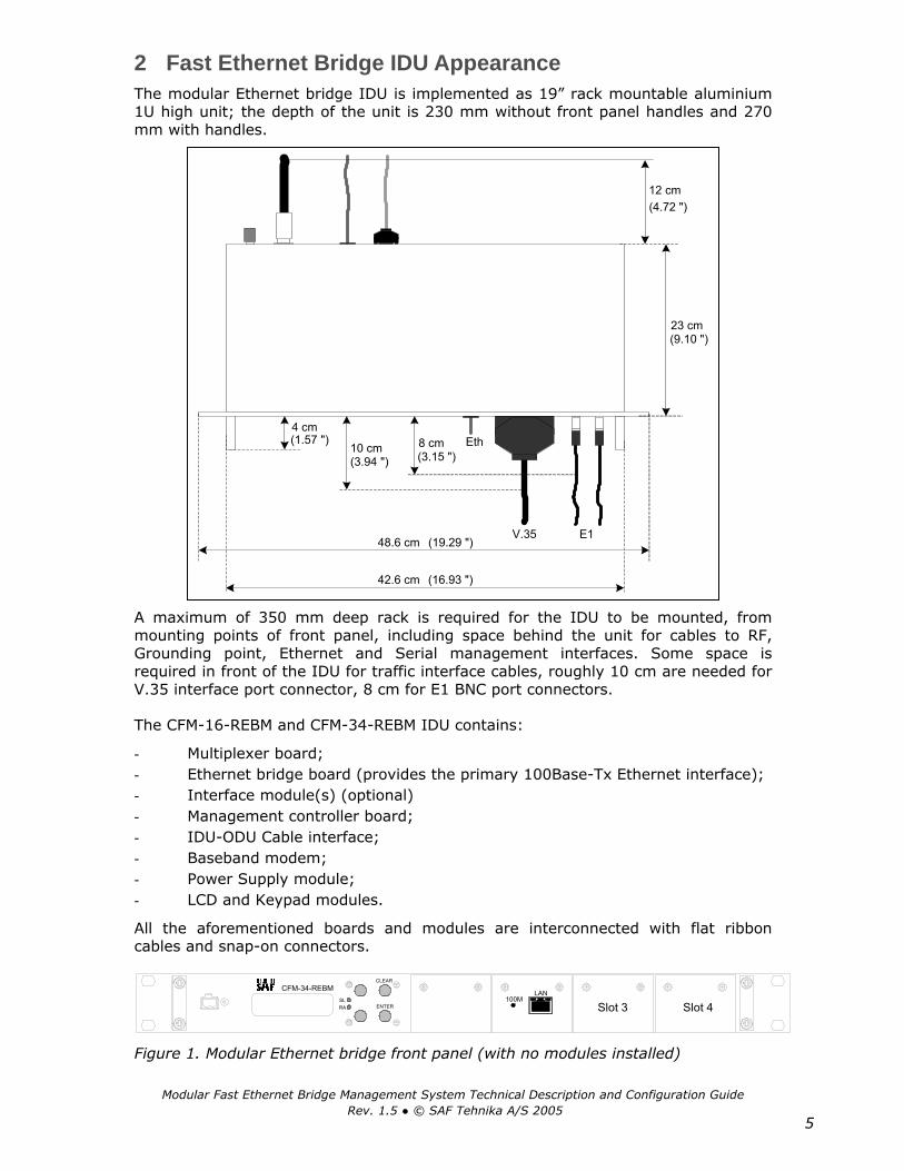
2 Fast Ethernet Bridge IDU Appearance The modular Ethernet bridge IDU is implemented as 19” rack mountable aluminium 1U high unit; the depth of the unit is 230 mm without front panel handles and 270 mm with handles.
A maximum of 350 mm deep rack is required for the IDU to be mounted, from mounting points of front panel, including space behind the unit for cables to RF, Grounding point, Ethernet and Serial management interfaces. Some space is required in front of the IDU for traffic interface cables, roughly 10 cm are needed for V.35 interface port connector, 8 cm for E1 BNC port connectors.
The CFM-16-REBM and CFM-34-REBM IDU contains:
- Multiplexer board; - Ethernet bridge board (provides the primary 100Base-Tx Ethernet interface); - Interface module(s) (optional) - Management controller board; - IDU-ODU Cable interface; - Baseband modem; - Power Supply module; - LCD and Keypad modules.
All the aforementioned boards and modules are interconnected with flat ribbon cables and snap-on connectors.
Figure 1. Modular Ethernet bridge front panel (with no modules installed)
8 cm10 cm
V.35 E1
4 cm
23 cm(9.10 ")
(3.15 ")(3.94 ")
(1.57 ")
(16.93 ")42.6 cm
(19.29 ")48.6 cm
12 cm(4.72 ")
Eth
LAN100M
CLEAR
ENTERSLRA
CFM-34-REBM
Slot 3 Slot 4

Modular Fast Ethernet Bridge Management System Technical Description and Configuration Guide Rev. 1.5 © SAF Tehnika A/S 2005
6
The CFM-16-REBM and CFM-34-REBM IDU provides:
- Interfaces to:
- Radio outdoor Unit (ODU), N-type female connector;
- 100Base-Tx Ethernet LAN port, for connection to LANs;
- RS-232 serial management port;
- 10Base-T Ethernet management port;
- LCD display and corresponding keypad buttons to control LCD;
- LAN activity LEDs (speed, link integrity);
- Power connector;
- Reset button;
- DIP switch for the primary bridge configuration.
Table 1. Connectors
Front panel connectors
Connector or label Description
+-48V Power connector, IDU should be powered from 20 to 60 VDC power source. Both “+” or “–“ poles of the power source could be grounded, one should make sure if the chosen grounding wire is connected to ground on the IDU power connector.
LAN 100Base-Tx Ethernet port (primary), shielded RJ-45 connector;
Interface module port connectors
Please refer to Chapter 3.
Rear panel connectors
Connector or label Description
RF (N-type connector)
Radio Unit port; Use 50 Ω coaxial cable with N-type male connectors on both sides to connect the ODU to the IDU, such as RG-213, LMR-400 or equivalent;
DB-9 RS232 management port for connection of ASCII console (or analog line modem for the remote connection of ASCII console); the RS232 console port is also used to update management software.
RJ-45 10Base-T Ethernet management port, this port is used to connect Telnet or Web terminal.

Modular Fast Ethernet Bridge Management System Technical Description and Configuration Guide Rev. 1.5 © SAF Tehnika A/S 2005
7
Table 2. Front panel LEDs
Label Color Description
RA Red Radio Alarm LED indicates problems with radio unit.
The following problems cause the Radio Alarm to switch on:
− Rx signal level is lower the predefined value, - the corresponding parameter is RxAlarmLev on the LCD or RxAlarmLevel using Telnet/ASCII console. The default value for this parameter is -77 dBm;
− The humidity within the radio is too high (possibly ODU is opened);
− Transmitter malfunction (TxOut=Error);
− RF Cable=Short – cable is faulty, RF Cable=Off – cable or Radio is faulty;
If not lit – operating properly (Rx=OK & TxOut=OK & Humidity=Low & RF Cable – OK); The RA LED will also switch on if the Radio loopback is switched on and/or if the transmitter power is switched off. The RA LED is updated one time per second.
SL Red Red Sync Lost LED indicates the multiplexer has lost synchronization; If not lit – operating properly; The SL LED is updated one time per second.
100M Green Indicates LAN port speed: ON – 100 Mbps, OFF – 10 Mbps
Green (right)
Indicates good LAN link integrity LAN port connector
LEDs Yellow (left)
LAN receiving data

Modular Fast Ethernet Bridge Management System Technical Description and Configuration Guide Rev. 1.5 © SAF Tehnika A/S 2005
8
Table 3. Rear side LEDs
The rear side LEDs refer to the operation of Ethernet port on the management module board.
LED Description
A If blinking (with a period of about 1 sec.), indicates operation of the management module CPU;
B If lit, indicates that Ethernet link is established with the management terminal;
C If blinking, indicates data interchange between the IDU and the management terminal;
Note: A, B and C correspondence to LEDs is shown in the figure below.
Figure 2. Rear side panel LEDs
For more information on Reset button please refer to the section 4.2.3.
2.1 Labeling The IDU label is found at the rear panel;
P/N – product number, the last two numbers denote the product version;
S/N – serial number.
The combination of product number and serial number uniquely identifies each unit.
Figure 3. Label of the CFM-34-REBM IDU
A B C
Hidden resetbutton

Modular Fast Ethernet Bridge Management System Technical Description and Configuration Guide Rev. 1.5 © SAF Tehnika A/S 2005
9
3 Interface modules
3.1 V.35 Interface Module V.35 interface module is provided with M34 type connector. In the modular Ethernet bridge the V.35 module terminates 2 Mbps from MUX and provides user selectable data rates of 64 kbps, 128 kbps, 256 kbps, 512 kbps, 1024 kbps and 2048 kbps to single V.35 interface on M.34 connector.
3.1.1 V.35 Interface Module LEDs
There are four LEDs on V.35 module, see Table 4 for information how to read them.
Table 4. V.35 interface module LEDs
LED Color Name Function Direction
TX Green
Data Transmitting
Active
Data activity - data is being transferred from module's front port to multiplexer.
V.35 MUX*
SL Red Signal Loss V.35 port failure.
LB Red Loopback
Active
Loopback on V.35 module is switched on, informing that the connection between V.35 port and MUX board is interrupted.
Dual, - there are actually two loopbacks active, please refer to chapter 4.5.3 for information about V.35 module loopbacks.
RX Green Data
Receiving Active
Data activity - data is being received from multiplexer board and transmitted to module front port
MUX V.35*
* - both TX and RX LEDs will flash simultaneously while the V.35 module loopback is switched on.

Modular Fast Ethernet Bridge Management System Technical Description and Configuration Guide Rev. 1.5 © SAF Tehnika A/S 2005
10
3.2 E1 Interface Module The E1 interface module is a single port module provided with two types of interfaces:
• 120 Ω balanced interface, accessible through RJ-45 type connector,
• 75 Ω unbalanced interface, requires a pair of coaxial cables with the BNC type connector.
Both interfaces terminate 2 Mbps (G.703) streams.
Table 5. E1 Interface module connectors
Out,
In
Two BNC connectors provide means to connect the CPE equipment to the IDU;
Tx data stream is transmitted over OUT (output) port;
Rx data is to be received through IN (input) port.
RJ-45 RJ-45 connector for balanced E1 interface.
Table 6. E1 interface module LEDs
Label Color Description
Tx Green Steady green light indicates the E1 module is ready to transmit data to CPE connected to E1 port.
In case if Multiplexer synchronization is lost (S.L. LED is lit), Tx LED goes off and AIS signal is transmitted from E1 port to CPE.
Rx Green Steady green light indicates the data signal from E1 input.
AIS Red Steady red LED indicates the AIS signal from E1 input.
LB Red “LoopBack” LED (red) indicates loopback mode is activated in the module.

Modular Fast Ethernet Bridge Management System Technical Description and Configuration Guide Rev. 1.5 © SAF Tehnika A/S 2005
11
3.3 10Base-T REB Interface Module The CFM series REB interface module features a complete filtering Ethernet bridge. The REB module terminates any capacity of 2-4-6-8 Mbps from the multiplexer on a single 10 Mbps 10Base-T UTP Ethernet port.
REB features: - Automatic learning and aging, - 256-frame buffer, - 10 000 MAC address table, - 15 000 frames per second filtering and forwarding rate. The REB does not support auto-negotiation and does not support VLAN tagging.
3.3.1 10Base-T REB Interface Module LEDs
There are two groups of LEDs on the front of the module:
• LRx, LTx
• WRx, WTx
WRx and WTx LEDs:
− Flickering green WTx LED indicates that data is being transmitted to WAN, − Flickering green WRx LED indicates that data is being received from WAN.
LRx and LTx LEDs:
− Switched off LRx LED indicates that Ethernet link is ok, no data is being received from LAN,
− Steady green LRx LED indicates that data is being received from LAN,
− Steady red LRx LED indicates that Ethernet link is lost on LAN side,
− Switched off LTx LED indicates that no data is being transmitted to LAN,
− Flash of orange LTx LED indicates LAN collision in case if Ethernet port of the REB module operates in Half Duplex mode,
− Flickering green LTx LED indicates that data is being transmitted to LAN.

Modular Fast Ethernet Bridge Management System Technical Description and Configuration Guide Rev. 1.5 © SAF Tehnika A/S 2005
12
3.4 2-port 100Base-T REB Interface Module The 2-port REB (Remote Ethernet Bridge) module is a high performance two port 10/100 Mbps Ethernet bridge with RJ-45 TP interfaces. Both TP interfaces have auto MDIX TX/RX swap function, and both ports support 10/100 Mbps Full/Half duplex modes with auto negotiation. The bridge supports 802.1Q VLAN packets.
The 2-port REB module is compatible with all CFM series Ethernet Bridge IDUs and 10Base-T REB Interface Module.
Features:
• 10M/100M Half/Full duplex auto-detect
• Store and forward architecture
• TP auto MDIX TX/RX swap
• 2048 MAC addresses table
• Aging function
• Supported packet length - up to 1522 bytes
• Supports 802.1Q VLAN
100 Mbps speed LED(yellow), -if this LED is switched on,the port speed is 100 Mbps
Ethernet link/activity LED(green), if flickers, indicatesdata transmission,
Figure 4. 2-port 100Base-T module LEDs

Modular Fast Ethernet Bridge Management System Technical Description and Configuration Guide Rev. 1.5 © SAF Tehnika A/S 2005
13
3.5 V.35-G.704 Converter Module The V.35-G.704 Converter module has the following functions:
− The V.35-G.704 module converts the WAN side E1 traffic to Nx64 kbps serial data channels on the LAN side via V.35 port. The V.35 port supports fractional (LAN-side) data rates from 64 kbps up to 1984 kbps (in PCM31 mode when 16th timeslot is not used) if uses E1 WAN interface.
− The V.35-G.704 module can also be used as a standard V.35 serial data transmission interface (unframed mode) supporting transfer rates of 64 kbps, 128 kbps, 256 kbps, 512 kbps, 1024 kbps, 2048 kbps, 4096 kbps, 6144 kbps and 8192 kbps.
Features:
• LAN port connector: M.34 female; • Compatible with ITU-T G.704 standard; • CRC4 error checking supported for E1 traffic; • Supports CAS and CCS signaling; • Can operate in unframed mode as a standard V.35 port with speeds from 64
kbps up to 2046 kbps.
Module supports internal, external and feedback synchronization.
3.5.1 V.35-G.704 Converter Module LEDs
LED Colors Description
TX Green ON if data is being transmitted from module to MUX (data from DTE), otherwise OFF.
SL Red, Yellow (Green+Red)
OFF if normal operation; RED if incoming E1 traffic is out of sync; YELLOW (Red+Green) if Radio Alarm is s witched on.
LB Red ON if loopback is enabled, OFF if normal operation mode.
RX Green ON if data is being received from MUX to module, otherwise OFF.

Modular Fast Ethernet Bridge Management System Technical Description and Configuration Guide Rev. 1.5 © SAF Tehnika A/S 2005
14
4 Management Interfaces
4.1 Reading the LEDs Refer to Chapter 2 (Table 2) and Chapter 3.
4.2 LCD/Keypad LCD display and keypad provides most basic method to locally configure and monitor the local CFM terminal (IDU + ODU).
The LCD is constantly backlit and is able to display 2 lines of 16 symbols each line.
The LCD operates in two modes, Status display and Setup mode, please refer to Flow Chart 1, page 49.
Keypad consists of 4 buttons:
ENTER is used to confirm the choice of displayed item or entered data as well as to switch from status display to setup mode.
CLEAR is used to cancel the choice or to move to previous menu level.
↑ ↓ Up/Down buttons are used:
- To switch between options for menu items displayed;
- To choose parameter to set up and to set its value.
4.2.1 “Status Display” Mode of the IDU LCD Management Interface
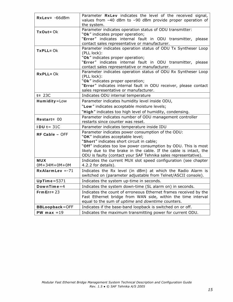
Once the IDU is powered up, it automatically enters “Status Display” mode, displaying two parameters at a time statically (use up/down buttons to scroll through parameters). These parameters are listed in the Table 7.
Table 7
Parameter Values and description
Tx=23362.5MHz Parameter indicates Tx frequency of the Radio. Rx=22354.5MHz Parameter indicates Rx frequency of the Radio. TxPower=+20dBm Parameter indicates Tx power of the Radio.
Rx= OK Rx parameter indicates various states of IDU receiver and ODU: “OK” indicates the IDU receives acceptable signal from ODU; “Low” indicates the received signal level is too low for the IDU to operate properly; “Error” indicates some internal fault in the ODU receiver, please contact sales representative or manufacturer.
Cable=–5 dB Parameter indicates signal attenuation in ODU-IDU cable, values of 0 … -20 dB provide proper operation of IDU.
Modular Fast Ethernet Bridge Management System Technical Description and Configuration Guide Rev. 1.5 © SAF Tehnika A/S 2005
15
RxLev= -66dBm Parameter RxLev indicates the level of the received signal, values from –40 dBm to –90 dBm provide proper operation of the system.
TxOut=Ok Parameter indicates operation status of ODU transmitter: “Ok” indicates proper operation; “Error” indicates internal fault in ODU transmitter, please contact sales representative or manufacturer.
TxPLL=Ok Parameter indicates operation status of ODU Tx Syntheser Loop (PLL lock): “Ok” indicates proper operation; “Error” indicates internal fault in ODU transmitter, please contact sales representative or manufacturer.
RxPLL=Ok Parameter indicates operation status of ODU Rx Syntheser Loop (PLL lock): “Ok” indicates proper operation; “Error” indicates internal fault in ODU receiver, please contact sales representative or manufacturer.
t= 23C Indicates ODU internal temperature Humidity=Low Parameter indicates humidity level inside ODU,
“Low” indicates acceptable moisture levels; “High” indicates too high level of humidity, condensing.
Restart= 00 Parameter indicates number of ODU management controller restarts since counter was reset.
IDU t= 31C Parameter indicates temperature inside IDU
RF Cable – OFF Parameter indicates power consumption of the ODU: “OK” indicates acceptable level; “Short” indicates short circuit in cable; “Off” indicates too low power consumption by ODU. This is most likely due to the brake in the cable. If the cable is intact, the ODU is faulty (contact your SAF Tehnika sales representative).
MUX 0M+34M+0M+0M
Indicates the current MUX slot speed configuration (see chapter 4.2.2 for details).
RxAlarmLev =-71 Indicates the Rx level (in dBm) at which the Radio Alarm is switched on (parameter adjustable from Telnet/ASCII console).
UpTime=5371 Indicates the system up-time in seconds. DownTime=4 Indicates the system down-time (SL alarm on) in seconds. FrmErr=23 Indicates the count of erroneous Ethernet frames received by the
Fast Ethernet bridge from WAN side, within the time interval equal to the sum of uptime and downtime counters.
BBLoopback=OFF Indicates if the base-band loopback is switched on or off. PW max =19 Indicates the maximum transmitting power for current ODU.

Modular Fast Ethernet Bridge Management System Technical Description and Configuration Guide Rev. 1.5 © SAF Tehnika A/S 2005
16
4.2.2 “Setup” Mode of the IDU LCD Management Interface
Following table describes parameters available for change by the CFM-16-REBM and CFM-34-REBM Indoor Unit in “Setup” mode.
Algorithm of LCD operation is shown on Flow Chart 1, page 49.
Table 8
Parameter Values and description
Change Chan ## “Change Chan” item provides ODU Tx and Rx frequency setup functionality: If this item is chosen LCD shows, for example:
where “163” – number of currently used Tx channel and “Tx” - frequency appropriate to channel. Channel numbers and corresponding Tx/Rx frequency values are found in the document “Channel plans”, see chapter 9.3 for details. Operator sets desired channel number scrolling through values with “Up” or “Down” buttons and confirming the choice with “Enter” button.
Tx Power +5dBm “TxPower” parameter sets the ODU Transmitter power rate. The default setting is “OFF”, allowing safe deployment of the equipment avoiding interference risk with other radio equipment.
Select IP Default value - 192.168.205.010 or 192.168.206.010 Select NETMASK Default value – 255.255.255.000
Important!: Do not enter address “255.255.255.255” Select Gateway Default value – 255.255.255.255 (No gateway specified) IP (IP address), Netmask and Gateway parameters provide the
means of addressing management board of IDU in order to control and manage IDU locally and monitor ODU both locally and remotely. Note: It is necessary to restart the management CPU for any changes in IP settings (including SNMP terminal IP settings) to take effect.
Access Code Specify the panel access code (a number from 0 – 200) to enable any adjustments from IDU.
Reset counters Resets up-time, down-time and Frame error counter, see page 34 for details.
RF loopback OFF Switches the RF loopback (Radio loopback) on or off. BB loopback ON Switches the baseband loopback on/off (BB loop analog – analog
base-band loop, BB loopback on – digital base-band loopback).
MUX speeds Sets the data rate for multiplexer slots (for slot numbering see Figure 1); the following configurations are available:
Data rate Designation Primary Ethernet Slot 3 Slot 4
0M+34M+0M+0M 34 Mbps 0 Mbps 0 Mbps 0M+30M+2M+2M 30 Mbps 2 Mbps 2 Mbps 0M+32M+0M+2M 32 Mbps 0 Mbps 2 Mbps 0M+32M+2M+0M 32 Mbps 2 Mbps 0 Mbps
The numbering of slots is shown in Chapter 2. Note: if no additional interface modules are used, the multiplexer should be configured as [0M+34M+0M+0M] to ensure maximum capacity (34 Mbps) of the primary Ethernet interface.
continued on next page

Modular Fast Ethernet Bridge Management System Technical Description and Configuration Guide Rev. 1.5 © SAF Tehnika A/S 2005
17
continued from previous page
Setup mode menu tree Access code Change * - current channel numberRestart CPU ** - multiplexer slot number
Reset Counters *** - Dloop - Digital loopbackWrite Config **** - Aloop - Analog loopbackLoopbacks RF loopback ON
RF loopback OFFBB loopback ONBB loop analog
BB loopback OFFOutdoor unit Chan ##* Change Chan ##
Power Tx PowerEthernet Select IP Change
Select NETMASK ChangeSelect Gateway Change
Modules Module #** Bridge Bridge interface Change FDX/HDXModule # E1 E1 Interface Ch. Interface
E1 Dloop*** Change DloopE1 Aloop**** Change Aloop
Module # V35 V.35 Speed Change SpeedV.35 Loopback Change Loopback
V.35 Clock Change ModeModule # F2Bridg Select: Port 1 P1 connection: auto Change Port 1
Port 1 priority: Low Change Port 1P1 Flow Cntrl.: Enable Change Port 1
Select: Port 2 P2 connection: auto Change Port 2Port 2 priority: Low Change Port 2
P2 Flow Cntrl.: Enable Change Port 2MUX Speeds ChangeService line Select local IP Change
Select remote IP Change
4.2.3 Reset Functions
Depending on the method used, the user may reset the whole terminal (IDU+ODU) or the management controller individually, see table below for details.
Reset through the LCD menu system using “Restart CPU” option or from the Telnet/ASCII console using “restartcpu” command
Restarts the management module. Resets all management counters.
Reset action using hidden button at the rear side of the IDU (see Figure 2)
Restarts both the multiplexer module and the management module. Resets all management counters. Note: This may require a pin, at least 15 mm long, approx. 1.5 mm in diameter.
Unplugging of power supply Restarts the multiplexer module and the management module. Resets all management counters.
Write config Saves all settings in EPROM of the management controller. Restart CPU Restarts management CPU for the new IP settings to take effect.
Resets all management counters. Modules This item contains all the commands for configuration of the
installed modules. See Setup Mode Menu Tree below for all commands available from “Modules” menu.

Modular Fast Ethernet Bridge Management System Technical Description and Configuration Guide Rev. 1.5 © SAF Tehnika A/S 2005
18
4.3 RS-232 Serial Management Port RS-232 serial management port of the IDU will provide terminal management via connected PC or other terminal or modem.
In order to interconnect the IDU and the management terminal directly through serial ports, a straight through modem cable is needed. The serial port of the management terminal should be configured as 19200 8-N-1, no data flow control.
Modem PC/TerminalModem
IDU
PC/Terminal
IDU RS-232
RS-232
If using modems, the management terminal is connected with the IDU remotely through a telephone line. In this case the modem, which is connected with the IDU, should be configured as stated below:
- Auto answer on first ring ON
- Echo offline commands OFF
- Suppress result codes
- DTR override
The modem configuration then should be saved (typically with AT&W string).
Telnet/ASCII management console command interface
For the pin assignments of the RS232 serial port, please refer to the CFM-LM series product family technical description. The document can be ordered from SAF Tehnika sales representatives or downloaded from SAF Tehnika’s Web site (see Chapter 0).

Modular Fast Ethernet Bridge Management System Technical Description and Configuration Guide Rev. 1.5 © SAF Tehnika A/S 2005
19
In order to connect the PC to the RS232 management port using Hyper Terminal program (this program is included in any Windows version), proceed as described below.
1. Connect PC to the RS232 serial port by means of “straight through” or modem serial cable (null-cable).
2. Run “Hyper Terminal” program. 3. Make a New connection, enter connection name.
4. Choose port (COM1 or COM2).

Modular Fast Ethernet Bridge Management System Technical Description and Configuration Guide Rev. 1.5 © SAF Tehnika A/S 2005
20
5. Set port settings (bits per second: 19200, data bits: 8, parity: none, stop bits: 1, no data flow control).
6. Press OK 7. Press Enter. Password is disabled by default.
If successfully connected, the prompt should appear as in the picture below; see Chapter 4.4.3 for available commands.

Modular Fast Ethernet Bridge Management System Technical Description and Configuration Guide Rev. 1.5 © SAF Tehnika A/S 2005
21
4.4 Ethernet Management Port Ethernet management port of the Fast Ethernet Bridge IDU is intended as main source of management connectivity and will provide the broadest range of management functionality:
- Web management via integrated Web server of management board; - SNMP management via integrated SNMP agent of management board; - Telnet server and CLI interface.
Ethernet interface could be used:
- To connect IDU to PC/Laptop to manage IDU; - To LAN for constant monitoring of IDU; - To router or any other TCP/IP packet network termination unit to have IDU as
part of network for management information.
4.4.1 Web Interface
The implementation of Web interface provides monitoring and configuration capabilities similar to ones available from the IDU LCD/Keypad, front panel LEDs, and from the Telnet/ASCII console, for details please refer to Chapters 4.2.1, 4.2.2, and 4.4.3.
The Web interface functionality is available via the Ethernet management port only.
Web interface is accessible by any standards based Web browser.
The CFM-34-REBM IDU Main Web management window: it shows the Radio characteristics, main system settings, and alarm status. Entries, which are highlighted in red, indicate that specific parameters do not comply with the norms of normal operation, all other parameters are satisfactory

Modular Fast Ethernet Bridge Management System Technical Description and Configuration Guide Rev. 1.5 © SAF Tehnika A/S 2005
22
To check the status of each module, click on a Module Status link to open the module status window.
The CFM-34-REBM Module Status window
When clicked on the link of any of the configuration windows for the first time since the main Web page was opened, you will be prompted to enter User Name and Password. The default username is SAF (in capital letters) and the default password is test. There are two configuration windows, - the Main Configuration window and the Module Configuration window. The following operations can be performed from the Main Configuration window: − restart the system, − save the current configuration, − change MUX slot speeds, − change the Web page refresh time.

Modular Fast Ethernet Bridge Management System Technical Description and Configuration Guide Rev. 1.5 © SAF Tehnika A/S 2005
23
Main Configuration window (not extended for Radio parameters)
The configuration of modules (including loopbacks) is available from the Modules Configuration window.
The CFM-34-REBM IDU Module Configuration Web management window

Modular Fast Ethernet Bridge Management System Technical Description and Configuration Guide Rev. 1.5 © SAF Tehnika A/S 2005
24
4.4.2 SNMP Interface
In order to receive SNMP traps from the IDU management controller, the IP address of the management PC with the installed Trap Manager software (based on SNMP platform) should be specified from a Telnet or ASCII console.
The IP address of the SNMP Trap Manager can be specified using the “SNMP trap <IPaddress>” command. The default value is 255.255.255.255 (no SNMP Trap Manager specified).
The Trap Manager address should be configured for each IDU, from which it is necessary to receive information on parameters, counters and alarms. The information is sent as SNMP Trap packets through the mediation of UDP protocol. If the Trap Manager terminal cannot be accessed, - for example, if there is no device connected to the Ethernet management port or IP settings of the management port are improper, a longer delay (about 10 sec.) may appear on the IDU startup.
SNMP management functionality is available from any SNMP browser, by means of compiling SAF MIB to browser’s MIB base.
SAF MIB is available from:
- SAF Tehnika Web site, www.saftehnika.com;
- From SAF Tehnika tech support, email: [email protected];
- Contacting SAF Tehnika or distributors.
Here is the sample of SNMP query of the CFM-34-REBM IDU ***** SNMP QUERY STARTED ***** sysDescr.0 (octets) SAF SNMP and WWW management sysObjectID.0 (oid) saf sysUpTime.0 (timeticks) 0 days 00h:33m:34s.90th (201490) productType.0 (int32) cfm-16(2) productDescr.0 (octets) SAF CFM-34-REBM description.0 (octets) SAF 23GHz microwave radio version.0 (octets) V2.16 2000.09.05 radioAlarm.0 (int32) on(1) signalAlarm.0 (int32) none(0) v_01.0 (octets) Tx=23362.5MHz v_02.0 (octets) Rx=22354.5MHz v_03.0 (octets) TxPower=+20dBm v_04.0 (octets) RxLev=-109dBm v_05.0 (octets) Cable=- 26dB v_06.0 (octets) TxOut=Ok v_07.0 (octets) TxPLL=Ok v_08.0 (octets) RxPLL=Ok v_09.0 (octets) t= 23C v_10.0 (octets) Humidity=Low v_11.0 (octets) Restart= 7 v_12.0 (octets) IDU t= 27C v_13.0 (octets) RF Cable - OFF v_14.0 (octets) MUX 0M+34M+0M+0M ***** SNMP QUERY FINISHED *****
Sample of SNMP query

Modular Fast Ethernet Bridge Management System Technical Description and Configuration Guide Rev. 1.5 © SAF Tehnika A/S 2005
25
The following table describes all variables defined in the MIB.
Variable Name Variable Type
Value List Description
termProduct String Textual name of terminal type termDescription String Textual description of terminal termLocation String IDU name termVersion String Textual version of management
software termOperation Integer (32 bit) none(0)
booting(1) ok(2) testing(3) error(4)
Terminal (IDU) operational status: none – not initialized; testing, illegalSpeed, error – reserved
termIduTemperature Integer (32 bit) Temperature within IDU (range: -128..127)
termRfCablePowerStatus Integer (32 bit) off(0) ok(1) short(2) error(3)
Indicates power consumption of the ODU: ok - acceptable level, short - short circuit in cable, off - too low power consumption, error – internal fault
termUpTime Integer (32 bit) System up-time in seconds termDownTime Integer (32 bit) System down-time in seconds bbVersion String Textual version of the Base-band
controller software bbOperation Integer (32 bit) none(0)
booting(1) ok(2) testing(3) loopback(4) illegalSpeed(5) error(6)
Operational status of the Base-band modem: none – not initialized loopback – Base-band loop is set on testing, illegalSpeed, error – reserved
bbLinkCapacity Integer (32 bit) Base-band link capacity in Kbps bbLinkCapacityDescription String Comment on Base-band link bbLoopback Integer (32 bit) off(0)
digital(1) analog(2)
Base-band loopback
bridgeLanLinkLostAlarm Integer (32 bit) none(0) on(1)
Link integrity on the Ethernet data port (UTP), none – normal operation on – link lost
rfOperation Integer (32 bit) none(0) booting(1) ok(2) testing(3) error(4) noDataFromODU(5)
Operational status of the Radio: none – not initialized testing, error – reserved noDataFromODU – no data is being received from ODU
rfAlarm Integer (32 bit) none(0) on(1)
Radio Alarm, none – off
rfVersion String Textual version of the Radio rfSide Integer (32 bit) low(0)
high(1) Band side of the Radio: low or high
rfChannel Integer (32 bit) Channel number rfTxFrequency String Tx frequency rfRxFrequency String Rx frequency rfTxPower Integer (32 bit) Transmitter power rfRxState Integer (32 bit) low(0)
ok(1) error(2) loopback(3)
Reception status: low – Rx signal level ok - normal error - internal fault in the Radio loopback – RF loop is set on
rfRxLevel Integer (32 bit) Received signal level [dBm] rfCableAttenuation Integer (32 bit) Signal attenuation in ODU-IDU cable
(0…-20 db - proper operation)

Modular Fast Ethernet Bridge Management System Technical Description and Configuration Guide Rev. 1.5 © SAF Tehnika A/S 2005
26
rfTxOut Integer (32 bit) error(0) ok(1) off(2)
Operation status of the ODU transmitter: ok – proper operation error – internal fault (no data from ODU) off – Tx power = off
rfTxPLL Integer (32 bit) error(0) ok(1)
Operation status of ODU Tx syntheser loop (PLL lock): ok – normal operation error - internal fault in ODU transmitter
rfRxPLL Integer (32 bit) error(0) ok(1)
Operation status of ODU Rx syntheser loop (PLL lock): ok – normal operation error - internal fault in ODU transmitter
rfOduTemperature Integer (32 bit) Internal temperature of ODU (0C) rfOduHumidity Integer (32 bit) low(0)
high(1) Humidity level inside ODU: low - acceptable moisture level
rfLoopback Integer (32 bit) off(0) on(1)
RF loopback
rfRxAlarmLevel Integer (32 bit) Rx level (in dBm) at which the Radio Alarm is switched on
brDescription String Textual description of the Bridge brVersion String Textual version of the Bridge brOperation Integer (32 bit) none(0)
booting(1) ok(2) testing(3) loopback(4) illegalSpeed(5) error(6)
Oprational status of the Bridge: none – not initialized testing, loopback, illegalOperation, error – reserved
brLanMode Integer (32 bit) other(0) halfDuplex(1) fullDuplex(2)
LAN duplex mode: other – not initialized;
brLanSpeed Integer (32 bit) LAN speed brLanLinkState Integer (32 bit) other(0)
linkOK(1) linkLOS(2)
LAN link integrity: other – not initialized;
*m3Type error(0) e1(33) v35(37) bridge(43) none(255)
Module type: error – internal fault none – no module installed or the module does not support data exchange with the management controller (e.g., due to the software)
m3Description String Description of the module m3Version String Textual version of the module m3Speed Integer (32 bit) Module data transfer speed in kbps m3Operation Integer (32 bit) none(0)
ok(2) loopback(4) illegalSpeed(5)
Operational status of the module: none – no data from the module loopback – loopback is switched on illegalSpeed – the speed configuration of the MUX slot does not mach the module speed
m3Rx Integer (32 bit) none(0) ok(1) noSignal(2) noLink(3) rxAIS(4)
Rx statuss of the module: none – not defined noLink – for the REB module only rxAIS – for the E1 module only
m3Tx Integer (32 bit) none(0) ok(1) noSignal(2) txAIS(4)
Tx statuss of the module: none – not defined noSignal – for V.35 module and REB module (same as no link or LOS alarm) txAIS – for E1 module only (usually switches on with the SL alarm)
m3Loopback Integer (32 bit) off(0) on(1) analog(2)
Loopback in the module

Modular Fast Ethernet Bridge Management System Technical Description and Configuration Guide Rev. 1.5 © SAF Tehnika A/S 2005
27
m3RxInput Integer (32 bit) other(0) coax(1) rj45(2) v35(3)
Rx input of the module: other – not initialised
m3TxMode Integer (32 bit) other(0) halfDuplex(1) fullDuplex(2)
Tx mode of the module (for the REB module only): other – not initialised
m3TxClockSource Integer (32 bit) other(0) master(1) slave(2)
Tx clock source of the module (for the V.35 module only): other – not initialised
m3TxClockPhase Integer (32 bit) other(0) normal(1) inverse(2)
Tx clock phase of the module (for the V.35 module only): other – not initialised
m3DataPolarity Integer (32 bit) other(0) normal(1) inverse(2)
Polarity of the data signal (for the V.35 module only) other – not initialised
* Note: There are more variables with the “m4” prefix in their names, they are analogical to those with the “m3” prefix; the “m3” denotes that the parameter refers to the module in the slot 3, “m2” – module in the slot 4.

Modular Fast Ethernet Bridge Management System Technical Description and Configuration Guide Rev. 1.5 © SAF Tehnika A/S 2005
28
4.4.3 Command Line Interface for Telnet/ASCII consoles
The command line management interface offers the widest configuration and monitoring functionality. The following tables summarize all available commands for Telnet and ASCII management terminals.
Common commands
Command Description
Time Show current date and time. Time <YYYY-MM-DD HH:mm:ss> Set the date and time on the IDU. Name <deviceName> Assigns a name to the IDU; The default name is “SAF”. Write Save all settings in the EPROM. This command saves all current
settings in EPROM, including those in the script. Ping <IPaddress> This command is for troubleshooting purposes to verify the
service channel connectivity, - sends a special packet to the remote IDU and then waits for a reply.
BBloop on | analog | off [duration]
Set baseband loopback, “on” – set digital loopback (dual), “analog” – set analog loopback (non-dual), “off” – suspend baseband loopback. Duration can be from 1 to 10 minutes, it is equal to 1 min. by default. Example: BBloop on 3
RFloop on | off [duration] Set RF loopback, - “on” – set loopback, “off” – suspend loopback. Duration can be from 1 to 10 minutes, it is equal to 1 min. by default. Example: Rfloop on 3
Webrefresh <refreshperiod> Refreshes the contents of WEB interface with a period specified with refreshperiod parameter. The period is given in seconds; the minimum period is 2 seconds. Example: webrefresh 5 – the web page will be updated after every 5 seconds.
RxAlarmLevel Set the Rx signal level at which the Radio Alarm is switched on. The default value is –77 dBm. Example: rxalarmlevel -55
DisableWDT Reset watchdog timer (restarts management controller, resets all management counters). Available from ASCII console only.
ResetWDT Reset watchdog timer (restarts management controller, resets all management counters).
ClearCounters Reset up-time and down-time counter, and Ethernet frame error counters, see page 34 for details.
Exit Close Telnet session (same as to press Ctrl+D) Disable telnet | www | snmp | rip
“telnet” – Disable Telnet interface “www” – Disable Web interface “snmp” – Disable SNMP interface “rip” – Disable RIP Note: after the command is entered, it is necessary to save the configuration in EPROM (use write command), and restart the IDU for changes to take effect.
Modular Fast Ethernet Bridge Management System Technical Description and Configuration Guide Rev. 1.5 © SAF Tehnika A/S 2005
29
Configuring IDU parameters
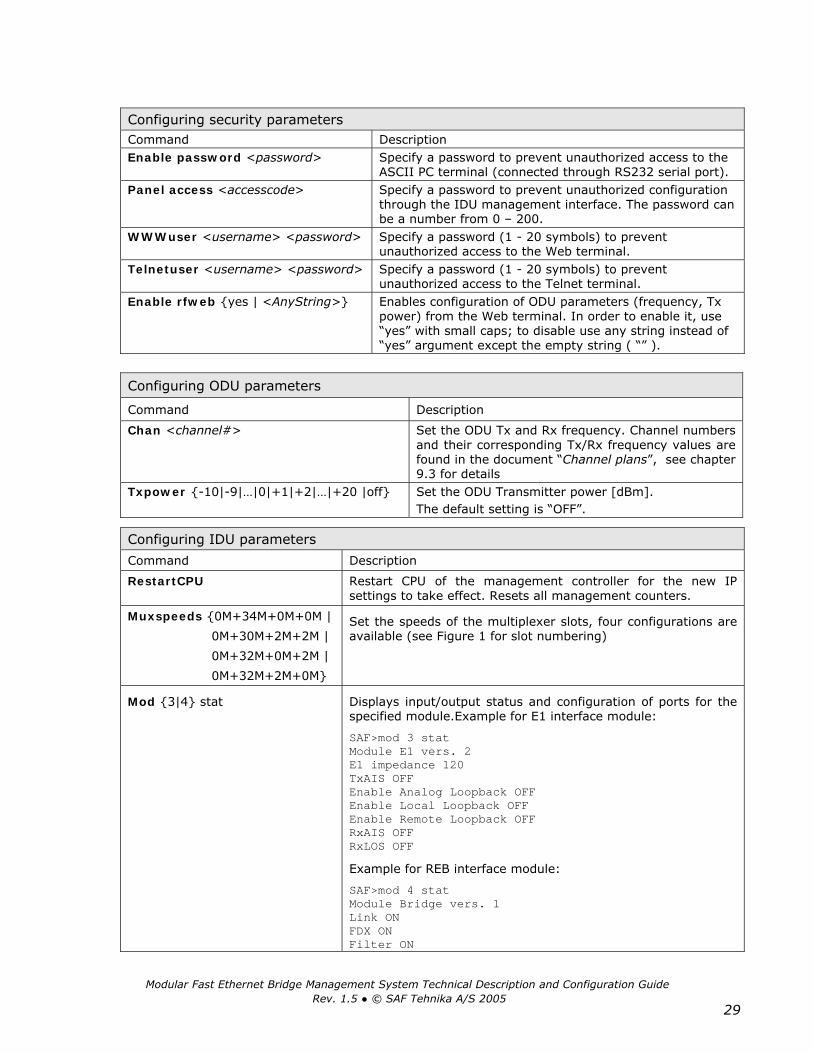
Command Description
RestartCPU Restart CPU of the management controller for the new IP settings to take effect. Resets all management counters.
Muxspeeds 0M+34M+0M+0M |
0M+30M+2M+2M |
0M+32M+0M+2M |
0M+32M+2M+0M
Set the speeds of the multiplexer slots, four configurations are available (see Figure 1 for slot numbering)
Mod 3|4 stat Displays input/output status and configuration of ports for the specified module.Example for E1 interface module:
SAF>mod 3 stat Module E1 vers. 2 E1 impedance 120 TxAIS OFF Enable Analog Loopback OFF Enable Local Loopback OFF Enable Remote Loopback OFF RxAIS OFF RxLOS OFF
Example for REB interface module:
SAF>mod 4 stat Module Bridge vers. 1 Link ON FDX ON Filter ON
Configuring security parameters Command Description Enable password <password> Specify a password to prevent unauthorized access to the
ASCII PC terminal (connected through RS232 serial port). Panel access <accesscode> Specify a password to prevent unauthorized configuration
through the IDU management interface. The password can be a number from 0 – 200.
WWWuser <username> <password> Specify a password (1 - 20 symbols) to prevent unauthorized access to the Web terminal.
Telnetuser <username> <password> Specify a password (1 - 20 symbols) to prevent unauthorized access to the Telnet terminal.
Enable rfweb yes | <AnyString> Enables configuration of ODU parameters (frequency, Tx power) from the Web terminal. In order to enable it, use “yes” with small caps; to disable use any string instead of “yes” argument except the empty string ( “” ).
Configuring ODU parameters
Command Description
Chan <channel#> Set the ODU Tx and Rx frequency. Channel numbers and their corresponding Tx/Rx frequency values are found in the document “Channel plans”, see chapter 9.3 for details
Txpower -10|-9|…|0|+1|+2|…|+20 |off Set the ODU Transmitter power [dBm]. The default setting is “OFF”.

Modular Fast Ethernet Bridge Management System Technical Description and Configuration Guide Rev. 1.5 © SAF Tehnika A/S 2005
30
Mod 3|4 detect Detect and show current settings, - displays a list of settings of the respective interface module. The detection procedure is carried out each time when IDU is started up. This command is for diagnostic purposes only.
Mod dump Show a list of modules and contents of their respective CPU registers (in hexadecimal system). This command is for diagnostic purposes only. Example: SAF>mod dump 21, 02, CD, FF, 00, 00, 00, 00, 78, 00, 00, FF, 00, 01, 77, 03, 25, 01, E0, E4, E4, FF, 08, FF, FF, FF, FF, FF, FF, FF, FF, FF, 25, 02, E7, E6, E7, FF, 81, FF, FF, FF, FF, FF, FF, FF, FF, FF, 2B, 01, 00, E0, FF, 00, 00, 00, 00, 00, 00, 00, 00, 00, 00, 00,
IP addr <IPaddress> Set the IP address of Ethernet management port (requires to restart the management module CPU).
Important!: Do not enter address “255.255.255.255”
IP mask <IPnetmask> Set the IP netmask of Ethernet management port (requires to restart the management module CPU).
IP gw <IPaddress> Set the IP address of the default gateway to the service channel (requires to restart the management module CPU).
IP seraddr <IPaddress> Set the IP address of the serial port of service channel for the local (near-end) IDU management module (requires to restart the management module CPU).
IP remaddr <IPaddress> Set the IP address of the serial port of service channel for the remote (far-end) IDU management module (requires to restart the management module CPU).
Route add <destinationIPaddr> Mask [netmask] <gateway> [metric]
Add a static route to the routing table. The variable “metric” is set to 1 by default. Example:
Route add 192.168.205.010 Mask 255.255.255.0 155.13.79.13 5
Route delete <destinationIPaddr> [netmask]
Delete a static route from the routing table.
SNMP community read <communityname>
Specify the SNMP community name of the agent to enable parameters to be read (not configured). The default community name to read parameters is saf-public
SNMP community write <communityname>
Specify the community name of the agent to enable parameters to be written (configured). The default community name for writing is saf-private
SNMP trap <IPaddress> Set the IP address of the management terminal with the installed Trap Manager software, based on SNMP platform (requires to restart the management module CPU).
Configuring E1 Interface Module parameters
Command Description
Mod 3|4 setE1 Aloop | Dloop | Off
Set the analog, digital or remote loopback in the module (Aloop – analog loopback; Dloop – digital loopback, off – disable current E1 module loopback).
Example: Mod 3 setE1 Dloop
Mod 3|4 setE1 120 | 75 Set the impedance of E1 interface, 120 Ω or 75 Ω. Mod 3|4 setE1 TxAIS on | off Enable/Disable the transmission of AIS signal (for
configuration and testing purposes only).

Modular Fast Ethernet Bridge Management System Technical Description and Configuration Guide Rev. 1.5 © SAF Tehnika A/S 2005
31
Configuring 2-port 100Base-T Ethernet Module parameters
Command Description
Mod 3|4 stat Displays bridge configuration, for example:
SAF>mod 1 stat Module Fast 2 Chan. Bridge vers. 2 Configuration Port 1 Speed: Auto Duplex: Auto Flow cntrl: Enabled Priority: Low Port 2 Speed: Auto Duplex: Auto Flow cntrl: Enabled Priority: Low Actual status Port 1 Link: Off Speed: 10Mb Duplex: Half Flow cntrl: On Port 2 Link: Off Speed: 10Mb Duplex: Half Flow cntrl: On
Mod 3|4 statistics Displays bridge port statistics, for example:
SAF>mod 1 statistics Module Fast 2 Chan. Bridge vers. 2 Statistics for last 1846 (sec.) Port 1 received packets: 0 Port 1 received bytes: 0 Port 1 transmitted packets: 0 Port 1 transmitted bytes: 0 Port 1 errors: 0 Port 1 collisions: 0 Port 2 received packets: 0 Port 2 received bytes: 0 Port 2 transmitted packets: 0 Port 2 transmitted bytes: 0 Port 2 errors: 0 Port 2 collisions: 0 WAN received packets: 0 WAN received bytes: 0 WAN transmitted packets: 0 WAN transmitted bytes: 0 WAN errors: 0
Mod 3|4 resetf2bridge Clears port statistics for both ports. Mod 3|4 setf2bridge port1 | port2 connection auto | 10fdx | 10hdx | 100fdx | 100hdx
Configure port speed, example: Mod 1 setf2bridge port2 connection 100fdx
Default value is auto. Mod 3|4 setf2bridge port1 | port2 priority low | high
Configure port priority.
Mod 3|4 setf2bridge port1 | port2 flowcntrl enable | disable
Enable or disable flow control for the specified port. This setting is applicable only for port(s) operating in full duplex mode.

Modular Fast Ethernet Bridge Management System Technical Description and Configuration Guide Rev. 1.5 © SAF Tehnika A/S 2005
32
Configuring V.35-G.704 Converter Module parameters Command Description Mod 3|4 setV35 master Set the sync status of V.35 module as master; the
SCTE signal is equal to TxC, which is generated by V.35 module clock generator.
Mod 3|4 setV35 slave Set the sync status of V.35 module as slave; the SCTE signal is equal to TxC, which is taken as RxC (SCTE=TxC=RxC).
Mod 3|4 setV35 ExtClock on | off Sets the sync status of V.35 module as slave, and TxC signal is not equal to SCTE, SCTE is received from external device (DTE).
Mod 3|4 setV35 TS 0|1|…|32|all Specifies the number of the first timeslot to be passed from incoming E1 frames to V.35 interface; arguments 0, 32, all will set the module to unframed mode in which the module works as a common V.35 interface. If the module is intended for operation in unframed mode, the TSC parameter must be set to one of the following values 0, 32, all
Mod 3|4 setV35 TSC 0|1|…|32|all Sets the total count of timeslots to be passed to V.35 interface, starting from timeslot specified with ‘setV35 TS’ command (first timeslot); arguments all, 0, 32 will select all available channels for a given mode: − for PCM30 mode – 30 channels will be selected, − for PCM31 mode – 31 channels will be selected, − for unframed mode – 32 channels will be selected
(total interface capacity 2048 kbps) If module works in unframed mode, then, if N is argument given for TS parameter, the module capacity will be equal to (N x 64) kbps if N = 1…32; if N = 0, all, the capacity is 2048 kbps (maximum available capacity).
Mod 3|4 setV35 TS16 on | off Determines mode of operation: “Off” selects PCM30 mode which use 15th timeslot for signalling and allows 30 of 32 timeslots to be used for data traffic; “On” selects PCM31 mode which does not use 15th timeslot, allowing 31 of 32 timeslots to be used for data traffic.
Mod 3|4 setV35 invTxD on | off Invert the incoming data signal (TxD, – module data input) between DCE (module) and DTE (user equipment).
Mod 3|4 setV35 invRxD on | off Invert the outgoing data signal (RxD, – module data output) between DCE and DTE.
Mod 3|4 setV35 invRxC on | off Invert the RxC clock signal (it is transmitted from V.35 module to user equipment)
Mod 3|4 setV35 invMUXdata on | off Inverts the data signal to\from Multiplexer Mod 3|4 setV35 loop on | off Sets the loop-back on\off in the Converter module;
during the loop-back, signal is looped back on both sides.
Mod 3|4 setV35 forceAIS on | off If set to ON, the timeslots of E1 frames will be filled with “1”
Mod 3|4 setV35 write Saves the current module settings in read-only memory, which is separate from EEPROM where configuration script is stored. When IDU is started, the settings that are stored in EEPROM for Converter module will take effect (not those stored in read-only memory of module).

Modular Fast Ethernet Bridge Management System Technical Description and Configuration Guide Rev. 1.5 © SAF Tehnika A/S 2005
33
Configuring V.35 Interface Module parameters
Command Description
Mod 3|4 setV35 speed 64 | 128 | 256 | 512 | 1024 | 2048
Set the speed of V.35 interface (in kbps).
Mod 3|4 setV35 polarity normal | inverse Set the polarity shift of the TxC signal.
Mod 3|4 setV35 loop on | off Set the loopback mode of V.35 interface module.
Mod 3|4 setV35 Master | Slave Set the status for synchronization of V.35 interface module, ie. master or slave.
Example: Mod 3 setV35 slave
Configuring REB Interface Module parameters
Command Description
Mod 3|4 setBridge Hdx | Fdx Set LAN port mode of the 10Base-T Ethernet module, full duplex or half duplex. Example: Mod 3 setbridge fdx
Mod 3|4 setBridge filter on | off
Switch on\off filtering mode for the bridge. By default filtering is switched on.
Verifying configuration and version
Command Description
Stat Show parameters, - lists all the parameters that are displayed in the status display mode of the IDU LCD.
Mac Verify the MAC address of the Ethernet management port.
ODU Show version of the ODU.
Ver Show version of the IDU.
Commands for script editing
Command Description
Cfg show Show the configuration script stored in RAM.
Cfg load Load the configuration script from EPROM into RAM.
Cfg clear Clear the script stored in RAM.
Cfg delete <stringNumber> Clear a single string in the configuration script. This command is useful for script editing.
Cfg write Save current script in EPROM. This command saves in EPROM the current script as well as settings that are specified in it.
Syntactic notes: − Commands are in bold font. − All arguments (variables) are in italic font. − Subcommands and keywords are in regular font. − Arguments in square brackets ([ ]) are optional but required arguments are in angle brackets
(<>). − Alternative keywords are grouped in braces ( ) and separated by vertical bars ( | ).

Modular Fast Ethernet Bridge Management System Technical Description and Configuration Guide Rev. 1.5 © SAF Tehnika A/S 2005
34
General
The management module has RAM and EPROM chips onboard. When IDU is booted up or management module CPU is restarted, bootstrap is loaded from the EPROM into RAM. The bootstrap contains all the parameters that was previously stored in EPROM using write and/or cfg write commands. These parameters are stored in EPROM in the form of script and when booting up, the script parameters are loaded into RAM. These parameters can be freely changed thus changing the contents of RAM. If the IDU is shut down without saving the current configuration in EPROM, the original configuration is restored from EPROM on the next boot-up.
Here is an example of script: SAF>cfg show 01: ip remaddr 192.168.0.11 02: ip seraddr 192.168.0.10 03: Chan 144 04: snmp community read safpub 05: snmp trap 255.255.255.255 06: route add 62.85.14.0 MASK 255.255.255.0 192.168.12.22
The script can be edited, e.g., strings can be added by simply entering the required command (the script will be supplemented with the new string or the instant string entry will be updated) and deleted using “cfg delete <string#>” command line. The changes of parameters can be saved in EPROM using cfg write command line.
To end Telnet/ASCII session press Ctrl+D.
The management software features system up-time and system down-time counters and the Fast Ethernet bridge has a built-in frame error counter. The down-time counter counts the seconds when the Signal Lost alarm is on whereas the up-time counter returns the system up-time (in seconds); the frame error counter counts erroneous Ethernet frames received by the Fast Ethernet bridge from the WAN. All aforementioned counters can be reset using clear counters command from Telnet or ASCII console or from IDU by selecting “Reset Counters” in the setup mode.
The management module has a watchdog timer (WDT) built in which manages the automatic restart of the management system if it freezes. Besides the restartCPU command, the management system can be reset using restartWDT command which breaks off check words to WDT thus causing the management system to restart. The watchdog timer can be turned off using disableWDT command (from Telnet/ASCII terminal) and can be turned on only by restarting the MUX and management module using hidden reset button or unplugging power.
Radio parameters
The radio parameter values (transmit frequency and power) are stored internally in Flash memory of the Radio unit, the Radio operates exactly with those values stored in its Flash memory. When the radio parameter is modified during the equipment is in operation, the corresponding radio parameter value in the Radio Flash memory is overwritten with the new one and applied in operation. Also, each time the equipment is booted, the radio parameter values written in the IDU bootstrap are uploaded to the Radio and the previously stored radio parameter values in Flash memory are overwritten with those in the IDU bootstrap. Hence the radio parameter configuration in the IDU bootstrap has a higher priority as they will override the values stored in the Radio on the equipment restart.
Consequently, the radio parameter configuration could be stored in the IDU bootstrap for the purpose to be able to quickly change the Radio unit later. Normally it is not necessary for the IDU bootstrap to contain strings that configure radio parameters.

Modular Fast Ethernet Bridge Management System Technical Description and Configuration Guide Rev. 1.5 © SAF Tehnika A/S 2005
35
IDU name
The IDU name permanently appears in the prompt string of the Telnet/ASCII terminal software, it can also be seen on the IDU LCD by pressing clear button while in status display mode as well as on the Web browser window.
The name of the IDU can only be assigned using Telnet or ASCII terminal, this cannot be done using IDU management interface.
The command line “Name <deviceName>” assigns a name to the IDU. The name can be a maximum of 16 symbols long. If using space(s), the argument should be in double quotes.
Example: Name “SAFterm2 14 7”
Security commands
For ASCII, Telnet and Web terminals only one user is supported. The default username and password for Telnet terminal is:
− Username: telnet − Password: saf
The default username and password for Web terminal is: − Username: SAF − Password: test
Take note of upper case and lower case type, it should be taken into account for both username and password! The passwords may contain spaces, if using space(s) the password should be entered in quote marks. For ASCII, Telnet and Web terminals the password can be changed simply re-entering the appropriate security command while logged on. To log off press Ctrl+D, the logging off is possible only if the password is specified. To disable password enter the password command appropriate for the specific terminal type followed by empty string, e.g., enable password “”.
Important! The specification of password (or username and password) should always be followed by saving the configuration script (using “write” or “cfg write” commands) otherwise the password request will be ignored after the restart of CPU. The panel access code for the access from IDU panel can be specified from the Telnet/ASCII console only. When the access code is specified the adjustment and configuration of any IDU/ODU parameters and loopbacks from IDU LCD is not available unless the correct access code is entered at the IDU (refer to “Setup” Mode of the IDU LCD Management Interface). The specification of access code should also be followed by saving the configuration script otherwise the access code value will be set to zero (none) on the CPU restart. The panel access code can be changed simply entering the new access code (number from 0 – 200) using panel access command. In order to disable the panel access code, enter 0 value. There is no default password set for ASCII terminal (ASCII console connected to RS232 management port) nor the access code from IDU panel is specified, - it is set to 0 (none).
Currently there are no possibilities to bypass password of any type of terminal, for instance if the user has forgotten it. The boot recovery functionality for such cases will be available in the upcoming software versions.

Modular Fast Ethernet Bridge Management System Technical Description and Configuration Guide Rev. 1.5 © SAF Tehnika A/S 2005
36
Real-time clock
The real-time clock does not provide any extra functionality at the moment, however in the upcoming management terminal software versions it will be used for the building of event logs. It is not available on the LCD of the IDU, the date and time can be viewed using time command when using ASCII or Telnet terminal. Date and time parameters can be set using Time <YYYY-MMM-DDD HH:mm:ss> command line.

Modular Fast Ethernet Bridge Management System Technical Description and Configuration Guide Rev. 1.5 © SAF Tehnika A/S 2005
37
4.5 Performing Loop-back Tests The following loop tests are available for the CFM-34-REBM site:
− Radio loopback,
− Base-band loopback,
− Traffic interface loopbacks.
The traffic interface loopback are not available for the primary Ethernet interface, nor installed Ethernet module(s).
Any loopback test can be set locally from IDU LCD, Telnet or ASCII console; the Web terminal allows to set loopbacks in the interface modules only.
4.5.1 Ethernet interface loop tests
The following schemes can be used to test either the primary 100Base-Tx or 10Base-T module Ethernet port:
− Setting local RF (if available), local baseband (digital or analog) or remote baseband loop, and then testing the bridge using any diagnostic device that generates packets and can process the returned data such as packet analyzers or any other Ethernet performance analyzing devices (see figure below).
Cab
le In
terfa
ce
ManagementControllerIDU
Management PC
Packet Analyzer
BasebandModem Multiplexer
Ethe
rnet
Brid
ge
Note: Before setting the digital baseband loopback, it is important to make sure the far-end Ethernet bridge is disconnected from the LAN since the base-band loopback is dual.
− Pinging the far-end host (connected to the traffic port of the far-end IDU, see figurte below) from the local host; this will verify both local (near-end) and remote (far-end) Ethernet ports.
Cab
le In
terfa
ce
BasebandModem
EthernetBridge
ManagementController IDU
ODU
Cab
le In
terfa
ce
BasebandModem
EthernetBridge
ManagementControllerIDU
ODU
PC PC
Traffic channel

Modular Fast Ethernet Bridge Management System Technical Description and Configuration Guide Rev. 1.5 © SAF Tehnika A/S 2005
38
4.5.2 Base-band and Radio loop tests
Base-band and Radio (RF) loopbacks can be set on a fixed time interval only; if using LCD/Keypad, the base-band and RF loop test is set for 1 minute. If setting base-band or RF loop from Telnet or ASCII console, the duration of the loopback mode can be specified from 1 to 10 minutes.
Radio loopback
The radio loop is set in the ODU. Radio loopback mode is a special ODU operation mode, where the Rx frequency during the loopback mode is set equal to the Tx frequency. During radio loopback mode, the signal is transmitted and looped back through the duplexer filter to the receiver block. The radio loopback is not dual.
Important notes:
1. Because of the frequency characteristic of the duplexer filter, in order to set the radio loop, the ODUs operating in the Low band side must be switched to the highest available frequency channel, but the ODUs operating in the High band side must be switched to the lowest available frequency channel;
2. Before setting the radio loop, the transmitter power should be switched to maximum level;
3. In CFM-18-LM and CFM-18-L4 ODUs the radio loopback mode is not available.
To set the radio loopback:
From Telnet or ASCII console:
use the following command: “RFloop on|off [duration]”, duration = 1 min by default.
Using LCD/Keypad:
in status display mode do the following: Press “ENTER” to enter setup mode → select “Loopbacks” → select “RFloopback ON” → select “Yes”.
Please refer to Chapter 4.4.1 to find out how the RF loop test is set from the Web terminal.
The operational capacity of the radio channel can be roughly rated by the indications of the frame error (FrmErr) counter of the Fast Ethernet Bridge, which counts the faulty Ethernet frames from WAN within the time interval equal the sum of up-time and down-time of the site.

Modular Fast Ethernet Bridge Management System Technical Description and Configuration Guide Rev. 1.5 © SAF Tehnika A/S 2005
39
Baseband loopbacks
There are two types of baseband loopbacks (both can not be activated simultaneously):
− Digital baseband loopback: the signal from the ODU and from the multiplexer (or Bridge board) in the baseband modem is looped back to the receiving device; the digital baseband loopback is dual (see figure below);
− Analog baseband loopback: the modulated signal on the baseband modem output is looped back to the receiving device and also passed further to the ODU.
Filter ComparatorClock recovery/Data decoding/Descrambling
ODU
Data coding/ScramblingFilter
Rx
Tx
Base-band Modem
Filter Comparator
ODU
Data coding/ScramblingFilter
Rx
Tx
Base-band Modem
Analog loop Digital loop (dual)
Clock recovery/Data decoding/Descrambling
From Telnet or ASCII console:
To set the base band loopback from Telnet or ASCII console, use the following command: “BBloop on|analog|off [duration]”.
Duration is set in minutes as values from 1 to 10. If duration is not specified the loopback will be set on 1 minute by default:
− Analog loop: if setting analog loopback, use “bbloop analog [duration]” command, analog loopback is not dual.
− Digital loop: to set the digital loopback, use “bbloop on [duration]” command, digital loopback is dual.
To switch off any of the baseband loopbacks use “bbloop off” command.
Using LCD/Keypad:
From status display mode do the following: Press “ENTER” to enter setup mode → select “Loopbacks” → select “BBloopback ON” or “BBloop analog“ → select “Yes”.
Proceed in the same way to switch off any of the baseband loopbacks.
Note: from the IDU LCD the baseband loopback is set on 1 minute.
Please refer to Chapter Web Interface to find out how the base band loop test is set from the Web terminal.
Modular Fast Ethernet Bridge Management System Technical Description and Configuration Guide Rev. 1.5 © SAF Tehnika A/S 2005
40
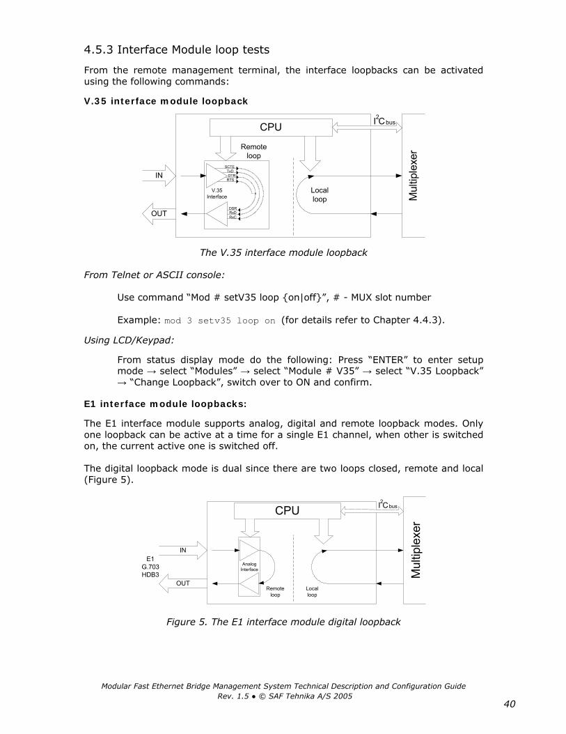
4.5.3 Interface Module loop tests
From the remote management terminal, the interface loopbacks can be activated using the following commands:
V.35 interface module loopback
CPU
OUT
IN
I C2
Remoteloop
Localloop
V.35Interface
RxDDSR
RxC
SCTETxDDTR
RTS
bus
Mul
tiple
xer
The V.35 interface module loopback
From Telnet or ASCII console:
Use command “Mod # setV35 loop on|off”, # - MUX slot number
Example: mod 3 setv35 loop on (for details refer to Chapter 4.4.3).
Using LCD/Keypad:
From status display mode do the following: Press “ENTER” to enter setup mode → select “Modules” → select “Module # V35” → select “V.35 Loopback” → “Change Loopback”, switch over to ON and confirm.
E1 interface module loopbacks:
The E1 interface module supports analog, digital and remote loopback modes. Only one loopback can be active at a time for a single E1 channel, when other is switched on, the current active one is switched off.
The digital loopback mode is dual since there are two loops closed, remote and local (Figure 5).
CPU
E1G.703HDB3
OUT
IN
Mul
tiple
xer
Remoteloop
Localloop
AnalogInterface
I C2bus
Figure 5. The E1 interface module digital loopback
Modular Fast Ethernet Bridge Management System Technical Description and Configuration Guide Rev. 1.5 © SAF Tehnika A/S 2005
41
CPU
E1G.703HDB3
OUT
IN
Mul
tiple
xer
AnalogInterface
I C2 bus
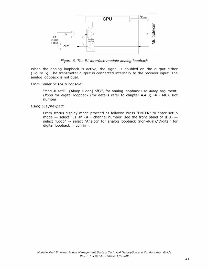
Figure 6. The E1 interface module analog loopback
When the analog loopback is active, the signal is doubled on the output either (Figure 6). The transmitter output is connected internally to the receiver input. The analog loopback is not dual.
From Telnet or ASCII console:
“Mod # setE1 Aloop|Dloop| off”, for analog loopback use Aloop argument, Dloop for digital loopback (for details refer to chapter 4.4.3), # - MUX slot number.
Using LCD/Keypad:
From status display mode proceed as follows: Press “ENTER” to enter setup mode → select “E1 #” (# - channel number, see the front panel of IDU) → select “Loop” → select “Analog” for analog loopback (non-dual),“Digital” for digital loopback → confirm.
Modular Fast Ethernet Bridge Management System Technical Description and Configuration Guide Rev. 1.5 © SAF Tehnika A/S 2005
42
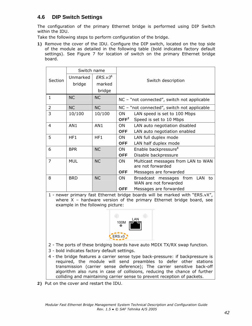
4.6 DIP Switch Settings The configuration of the primary Ethernet bridge is performed using DIP Switch within the IDU. Take the following steps to perform configuration of the bridge.
1) Remove the cover of the IDU. Configure the DIP switch, located on the top side of the module as detailed in the following table (bold indicates factory default settings). See Figure 7 for location of switch on the primary Ethernet bridge board.
2) Put on the cover and restart the IDU.
Switch name
Section Unmarked
bridge
ERS.v31
marked
bridge
Switch description
1 NC NC NC – “not connected”, switch not applicable
2 NC NC NC – “not connected”, switch not applicable 3 10/100 10/100 ON LAN speed is set to 100 Mbps
OFF2 Speed is set to 10 Mbps 4 AN1 AN1 ON LAN auto negotiation disabled
OFF LAN auto negotiation enabled 5 HF1 HF1 ON LAN full duplex mode
OFF LAN half duplex mode 6 BPR NC ON Enable backpressure3
OFF Disable backpressure 7 MUL NC ON Multicast messages from LAN to WAN
are not forwarded OFF Messages are forwarded
8 BRD NC ON Broadcast messages from LAN to WAN are not forwarded
OFF Messages are forwarded 1 - newer primary fast Ethernet bridge boards will be marked with “ERS.vX”,
where X – hardware version of the primary Ethernet bridge board, see example in the following picture:
LAN100M
ERS.v3
2 - The ports of these bridging boards have auto MDIX TX/RX swap function. 3 - bold indicates factory default settings. 4 - the bridge features a carrier sense type back-pressure: if backpressure is
required, the module will send preambles to defer other stations transmission (carrier sense deference); The carrier sensitive back-off algorithm also runs in case of collisions, reducing the chance of further colliding and maintaining carrier sense to prevent reception of packets.

Modular Fast Ethernet Bridge Management System Technical Description and Configuration Guide Rev. 1.5 © SAF Tehnika A/S 2005
43
12
34
56
78
Primary EthernetBridge board
ON
12
34
56
78
ON
Figure 7. The DIP Switch is located on the bridge module (encircled within white rectangle).
Caution. Be careful when setting jumpers or performing any actions while IDU cover is removed so that you do not bend or break any components.

Modular Fast Ethernet Bridge Management System Technical Description and Configuration Guide Rev. 1.5 © SAF Tehnika A/S 2005
44
4.7 Configuring Management Service Channel Before using the Management Service Channel, the mandatory precondition is to properly configure the following parameters:
– IP addresses of the local and remote service channel virtual serial port (also referred as service channel IP addresses): the IDU Management Module has a virtual serial port onboard that is used to receive/transmit the management information from/to the other virtual serial port on the far-side via service channel, both of these ports have their IP address.
– IP address and net-mask of the Management Module
– IP address of the gateway or host that is locally connected to the IDU.
The console is connected to the IDU via Ethernet console port located on the Management Module. The console should be configured so as to have routing information to the virtual serial port (service channel port) of the local IDU, - it should either run the RIP thereby automatically obtaining the routing information, or a static route should be added.
The routing requires determining IP addresses of service channels (virtual serial port IP addresses). Since the Management Module operates as a router between two subnets running the RIP 2, normally it is not necessary to configure the routing by adding static routes.
Virtual serial port IP addresses can be picked from the “private internet” addresses, e.g., 10.X.X.X or 192.168.X.X. Both of these addresses should be different from those used for addressing the IDU, the principle is shown in the picture below, here each cloud depicts a subnet.
Eth
(RJ-
45) 2-port
Router Seria
lPo
rt
Seria
lPo
rt
ManagementModule
Servicechannel

Modular Fast Ethernet Bridge Management System Technical Description and Configuration Guide Rev. 1.5 © SAF Tehnika A/S 2005
45
The configuration of local and remote virtual service channel IP addresses should conform the following principle:
Terminal A Terminal B
Local virtual serial port IP address IP 1 IP 2
Remote virtual serial port IP address IP 2 IP 1
service channel
Eth
VirtualSerialPort
ManagementModule(router)
Eth
VirtualSerialPort
ManagementModule(router)
Remote virtual serialport IP address
Remote virtual serialport IP address
Local virtual serial portIP address
Local virtual serial portIP address
ManagementConsole
Required to specify:IP address/Net Mask,Default Gateway
Local Site (Terminal A) Remote Site (Terminal B)
Required to specify:Local serial port IP addr.,Remote serial port IP addr.
Required to specify:Local serial port IP addr.,Remote serial port IP addr.
See examples on the next page.

Modular Fast Ethernet Bridge Management System Technical Description and Configuration Guide Rev. 1.5 © SAF Tehnika A/S 2005
46
Examples of service channel configuration
service channel
Eth
VirtualSerialPort
ManagementModule
RIP = ON
Eth
VirtualSerialPort
ManagementModule
RIP = ON
Telnet console/Web client
IP Addr 192.168.205.10IP mask 255.255.255.0IP GW 192.168.205.1
Local Site (Terminal A) Remote Site (Terminal B)
IP Seraddr 192.168.0.10IP Remaddr 192.168.0.11
IP Seraddr 192.168.0.11IP Remaddr 192.168.0.10
IP Addr 192.168.206.10IP mask 255.255.255.0
Console IP address: 192.168.205.1, 255.255.255.0Route Add 192.168.206.0 Mask 255.255.255.0 192.168.205.10
Figure 8
service channel
Eth
VirtualSerialPort
ManagementModule
RIP = ON
Eth
VirtualSerialPort
ManagementModule
RIP = ON
Telnet console/Web client
IP Addr 192.168.205.10IP mask 255.255.255.0IP GW 192.168.205.1
Local Site (Terminal A) Remote Site (Terminal B)
IP Seraddr 192.168.0.10IP Remaddr 192.168.0.11
IP Seraddr 192.168.0.11IP Remaddr 192.168.0.10
IP Addr 192.168.206.10IP mask 255.255.255.0IP GW 192.168.0.10
Router port IP address: 192.168.205.1, 255.255.255.0Route Add 192.168.206.0 Mask 255.255.255.0 192.168.205.10
Router(RIP=OFF)
Ethernet
Figure 9

Modular Fast Ethernet Bridge Management System Technical Description and Configuration Guide Rev. 1.5 © SAF Tehnika A/S 2005
47
Ethernet
service channel
Eth
VirtualSerialPort
ManagementModule
RIP = ON
Telnet console/Web clientIP address: 192.168.204.2
IP Addr 192.168.205.2IP mask 255.255.255.252IP GW 192.168.205.1
IP Seraddr 192.168.0.1IP Remaddr 192.168.0.2
IP Seraddr 192.168.0.2IP Remaddr 192.168.0.1
IP Addr 192.168.205.5IP mask 255.255.255.252IP GW 192.168.0.1
Port IP address: 192.168.204.1
Router(RIP = OFF)
Eth
VirtualSerialPort
ManagementModule
RIP = ON
Eth
VirtualSerialPort
ManagementModule
RIP = ON
IP Addr 192.168.205.6IP mask 255.255.255.252IP GW 192.168.205.5
IP Seraddr 192.168.0.3IP Remaddr 192.168.0.4
service channel
Eth
VirtualSerialPort
ManagementModule
RIP = ON
IP Seraddr 192.168.0.4IP Remaddr 192.168.0.3
IP Addr 192.168.205.9IP mask 255.255.255.252IP GW 192.168.0.3
Hop 1
Hop 2
Port IP address: 192.168.205.1Route Add 192.168.205.0 Mask 255.255.255.240 192.168.205.2
Eth
VirtualSerialPort
ManagementModule
RIP = ON
IP Addr 192.168.205.13IP mask 255.255.255.252IP GW 192.168.0.5
IP Seraddr 192.168.0.6IP Remaddr 192.168.0.5
service channel
Eth
VirtualSerialPort
IP Seraddr 192.168.0.5IP Remaddr 192.168.0.6
IP Addr 192.168.205.10IP mask 255.255.255.252IP GW 192.168.205.9
Hop 3
ManagementModule
RIP = ON
Figure 10. The IP configuration of the management channel via three hops with the RIP II switched on in each IDU; since the management controllers are running RIP II, there is no necessary to specify gateway (see configuration strings in grey)

Modular Fast Ethernet Bridge Management System Technical Description and Configuration Guide Rev. 1.5 © SAF Tehnika A/S 2005
48
Ethernet
service channel
Eth
VirtualSerialPort
ManagementModule
RIP = OFF
Telnet console/Web client
IP Addr 192.168.205.2IP mask 255.255.255.252
IP Seraddr 192.168.0.1IP Remaddr 192.168.0.2
IP Seraddr 192.168.0.2IP Remaddr 192.168.0.1
IP Addr 192.168.205.5IP mask 255.255.255.252
Port IP address: 192.168.204.1
Router(RIP = OFF)
Eth
VirtualSerialPort
ManagementModule
RIP = OFF
Eth
VirtualSerialPort
ManagementModule
RIP = OFF
IP Addr 192.168.205.6IP mask 255.255.255.252
IP Seraddr 192.168.0.3IP Remaddr 192.168.0.4
service channel
Eth
VirtualSerialPort
ManagementModule
RIP = OFF
IP Seraddr 192.168.0.4IP Remaddr 192.168.0.3
IP Addr 192.168.205.9IP mask 255.255.255.252
Hop 1
Hop 2
Port IP address: 192.168.205.1Route Add 192.168.205.0 Mask 255.255.255.240 192.168.205.2
Eth
VirtualSerialPort
ManagementModule
RIP = OFF
IP Addr 192.168.205.13IP mask 255.255.255.252
IP Seraddr 192.168.0.6IP Remaddr 192.168.0.5
service channel
Eth
VirtualSerialPort
IP Seraddr 192.168.0.5IP Remaddr 192.168.0.6
IP Addr 192.168.205.10IP mask 255.255.255.252
Hop 3
ManagementModule
RIP = OFF
IP GW 192.168.205.1Route add 192.168.205.12 Mask 255.255.255.252 192.168.0.2Route add 192.168.205.4 Mask 255.255.255.252 192.168.0.2Route add 192.168.205.8 Mask 255.255.255.248 192.168.0.2
IP GW 192.168.0.1Route add 192.168.205.8 Mask 255.255.255.248 192.168.205.6Route add 192.168.205.13 Mask 255.255.255.255 192.168.205.6
IP GW 192.168.0.3Route add 192.168.205.13 Mask 255.255.255.255 192.168.205.10
IP GW 192.168.205.9Route add 192.168.205.13 Mask 255.255.255.255 192.168.0.6
IP GW 192.168.205.5Route add 192.168.205.8 Mask 255.255.255.248 192.168.0.4Route add 192.168.205.13 Mask 255.255.255.255 192.168.0.4
Route add 192.168.205.0 Mask 255.255.255.240 192.168.204.1
IP GW 192.168.0.5
Figure 11. The IP configuration of the management channel via three hops with the RIP II switched off in each IDU; for proper routing between IDU management modules, the default gateway and static routes must be set for each module
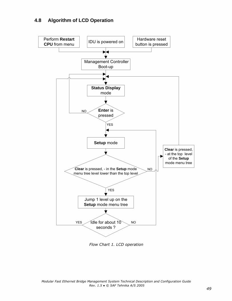
Modular Fast Ethernet Bridge Management System Technical Description and Configuration Guide Rev. 1.5 © SAF Tehnika A/S 2005
49
4.8 Algorithm of LCD Operation
Management ControllerBoot-up
Enter ispressed
Status Displaymode
IDU is powered on Hardware resetbutton is pressed
Perform RestartCPU from menu
Setup mode
NO
YES
YES
NO
Jump 1 level up on theSetup mode menu tree
Clear is pressed, - in the Setup modemenu tree level lower than the top level
YES
Clear is pressed,- at the top level
of the Setupmode menu tree
Idle for about 10seconds ?
NO
Flow Chart 1. LCD operation

Modular Fast Ethernet Bridge Management System Technical Description and Configuration Guide Rev. 1.5 © SAF Tehnika A/S 2005
50
4.9 Replacing the Indoor Unit Before replacing the IDU, verify the configuration of Radio if possible, - inspect the channel an transmit power settings. Then configure the new IDU in one of the following ways:
− delete the bootstrap via Telnet or ASCII console using cfg clear command, or − configure Radio channel and transmit frequency as needed (from LCD or via
management console);
In order to replace the faulty IDU while in operation, take the following steps:
− Disconnect the faulty IDU from the Radio: disconnect the N-type female connector; unplugging of power is optional;
− Connect the new IDU: if the new IDU is previously configured (the transmit power and
channel settings are made and the configuration is saved), the Radio will apply these settings after the management controller will be restarted,
if configuration script (bootstrap) is empty or does not contain entries on channel and transmit power, the Radio will keep the configuration that was last received from IDU;
− Restart the management controller, for instance, using RestartCPU option on the LCD.
4.10 Updating Management Software Updates to management software for management controller board will be available as uploadable files from SAF Tehnika company, sales partners or Web site.
Upload functionality is provided via management controller software monitor function and is available on RS-232 serial port.
The upload can be performed using
− PC/Laptop connected to IDU serial port, using ‘SAF Firmware Uploader’ program, found on the documentation CD, the instructions how to use this software can be found in its installation directory.
− PC/Laptop connected to serial port of IDU, using any terminal emulation program with text file transferring functionality; the instructions how to update software using this method are given in “Management Software Update Guide”.

Modular Fast Ethernet Bridge Management System Technical Description and Configuration Guide Rev. 1.5 © SAF Tehnika A/S 2005
51
4.11 Default Settings
Parameter name or command line Parameter/description Telnet / ASCII LCD
Default value/setting
Tx/Rx channel Chan Chan
In the middle of the band covered by Radio
Transmitter power Txpower Tx Power Off
Rx signal level by which the Radio Alarm is switched on
RxAlarmLevel RxAlarmLev -71 dBm
Fdx/Hdx port mode for Ethernet bridges (for Ethernet and Fast Ethernet bridge IDUs only)
Bridge Bridge Ethernet
Hdx
Management controller IP address
IP addr IP 192.168.205.10 or 192.168.206.10
Management controller IP address netmask
IP mask Netmask 255.255.255.0
IP address of the gateway to the service channel
IP gw Gateway 255.255.255.255
IP address of the local virtual serial port of service channel
IP seraddr Local IP 192.168.0.10
IP address of the remote virtual serial port of service channel
IP remaddr Remote IP 192.168.0.11
IDU name Name - SAF
SNMP community name of the agent to read (not configure) the parameters
SNMP community read
- saf-public
SNMP community name of the agent to write
SNMP community write
- saf-private
IP address of the SNMP trap manager
SNMP trap - 255.255.255.255 - trap manager not specified
Web page refresh time Webrefresh - 5 seconds
Username and password for ASCII console
Enable password
- (disabled)
Access number for LCD/Keypad Panel access - 0 (disabled)
Username and password for Web terminal
WWWuser - Username: SAF
Password: test
Username and password for Telnet terminal
Telnetuser - Username: telnet
Password: saf
Configuration of Radio parameters from the Web terminal
Enable rfweb - (disabled)

Modular Fast Ethernet Bridge Management System Technical Description and Configuration Guide Rev. 1.5 © SAF Tehnika A/S 2005
52
5 Configuring Radio Parameters
5.1 Default ODU Settings SAF Tehnika is shipping Radio units with disabled Transmitter (TxPower OFF) and channel is set to one in the middle of respective A or B side of the Low or High subband (Radio types: LA, HA, LB, HB), or in the middle of the whole Low or High subband (Radio types: L and H).
5.2 Configuring Tx Frequency The Tx frequency of the CFM LM and the CFM L4 type ODUs can be adjusted in the following ways:
1. It can be set through “Set Channel” item of IDU LCD menu system.
If this item is chosen, display indicates:
Where “Channel” corresponds to Tx channel number and “Tx frequency” indicates appropriate frequency in MHz.
Operator sets desired channel number scrolling through values with “Up” or “Down” buttons and confirming the choice with “Enter” button.
2. The Tx frequency can be set using “Chan” command from ASCII or Telnet management terminal, example: Chan 22
22 – channel number.
Since the telemetry data is transmitted between the ODU and the IDU, the concordance of Tx frequency to Low or High band side is detected automatically, and when the Tx channel is configured from the IDU LCD, the LCD displays frequencies within the subband (Low or High) that is covered by the ODU. However, if the ODU covers only a half of the subband (types: LA, HA, LB or HB, - depending on the duplexer filter within the ODU), the user should only choose from those Tx frequencies (channels) that are covered by the half of the subband specific to the ODU.
If a fault occurs in the ODU that prevents the transmission of telemetry data, the IDU LCD shows “No data from ODU”.
The Rx frequency is set automatically by Tx frequency.
Channel = xxx Tx = xxxxx.x MHz

Modular Fast Ethernet Bridge Management System Technical Description and Configuration Guide Rev. 1.5 © SAF Tehnika A/S 2005
53
5.3 Configuring Tx Power The Tx Power level of the CFM Radio can be adjusted in the following ways:
1. It can be set through “Set TxPower” item of IDU LCD menu system.
2. The Tx Power can be adjusted using “Txpower” command from Telnet or ASCII management console, example: Txpower +10
The Tx Power can be adjusted from -10 dBm to +20 dBm in steps of 1 dBm as well as switched off (Txpower off).
To avoid possible interference with other radio equipment, the default setting is “OFF”.
5.4 RSSI Port RSSI (Received Signal Strength Indicator) port is used to adjust the alignment of antenna for best performance (for both rough and fine adjustment); this can be done using digital multimeter which is connected to the RSSI port. The output of the RSSI port is DC voltage and varies depending on received signal level.

Modular Fast Ethernet Bridge Management System Technical Description and Configuration Guide Rev. 1.5 © SAF Tehnika A/S 2005
54
6 Pinouts RS-232 management interface pinouts
Unassigned
Unassigned
DB9 Female Connector
Received from DTETransmitted from DCE
Transmitted Data
Received Data
DTE Ready
Signal Ground
DCE Ready
Clear to Send
Request to Send
Shield
1
2
3
4
5
6
7
8
9
Notes:
− Standard Ethernet patch cables should be used for the Ethernet management port of IDU;
− Any “straight-through” or modem serial cable can be used for the RS-232 Telnet/ASCII console port.
E1 and Ethernet interface pinouts
1 2 3 4 5 6 7 8
Tx Rx
1 2 3 4 5 6 7 8
RxTx
Cable pinouts for E1interface
Cable pinouts for Ethernetinterface
1 2 3 4 5 6 7 8
portINPUT (Rx)
OUTPUT (Tx)

Modular Fast Ethernet Bridge Management System Technical Description and Configuration Guide Rev. 1.5 © SAF Tehnika A/S 2005
55
V.35 traffic interface pinouts
Ethernet interface pinouts
Ethernet device/port Tx pins Rx pins Comment
10Base-T Ethernet management port 1, 2 3, 6 As PC network cards
10Base-T REB module (1-port) 1, 2 3, 6 As PC network cards
REBM IDU primary Fast Ethernet bridge port (100Base-T)
3, 6 1, 2 As Hubs and Switches
2-port 100Base-T Ethernet module Auto MDIX Tx/Rx swap
Signal M34 Pin 60 Pin Cisco*
P GND A 46 S GND B 45 RTS C 42 CTS D 35 DSR E 34 DCD (RLSD) F 33 DTR H 43 TxD+ P 18 TxD- S 17 RxD+ R 28 RxD- T 27 SCTE+ U 20 SCTE- W 19 RxC+ (SCR+) V 26 RxC- (SCR-) X 25 TxC+ (SCT+) Y 24 TxC- (SCT-) AA 23
Interconnectable pinouts at the Cisco equipment side: 48 & 49 50 & 51 & 52 53 & 54 & 55 & 56
Notes:
* This information is for user’s reference only P GND – Protection Ground S GND – Signal Ground

Modular Fast Ethernet Bridge Management System Technical Description and Configuration Guide Rev. 1.5 © SAF Tehnika A/S 2005
56
7 Mechanical Data
Dimensions HxWxD [mm] 44x482x284
Maximum weight [kg] 2.1
Dimensions of the IDU
482
284
44
LAN100M
CLEAR
ENTERSLRA
CFM-34-REBMSAF||| |||

Modular Fast Ethernet Bridge Management System Technical Description and Configuration Guide Rev. 1.5 © SAF Tehnika A/S 2005
57
8 SAF Tehnika A/S Contacts Most up to date contacts of SAF Tehnika A/S could be found at Web site www.saftehnika.com.
SAF Tehnika A/S technical support could be reached at:
- Email: [email protected]
- Telephone: +371 7046840
- Fax: +371 7020009

Modular Fast Ethernet Bridge Management System Technical Description and Configuration Guide Rev. 1.5 © SAF Tehnika A/S 2005
58
9 References All the documents comprised in this chapter can be ordered from the SAF Tehnika or its sales representative.
9.1 Technical Description • SAF CFM-LM Series Product Family Technical Description
This document is a comprehensive technical description of the CFM LM type IDUs, it comprises the installation and commissioning issues and respective accessories, functional descriptions, technical data, a.o.
9.2 Configuration Guides Configuration guides provide the necessary information regarding the configuration of SAF Tehnika’s CFM products, these documents mostly describe the management system and methods to configure the equipment.
The following configuration guides are available for the modular Ethernet bridge equipment:
• CFM-4-REB and CFM-8-REB Ethernet Bridge: Indoor Unit Management System Technical Description and Configuration Guide
• CFM Series E1 Indoor Units: Management System Technical Description and Configuration Guide
• CFM Modular Multiplexer: Indoor Unit Management System Technical Description and Configuration Guide
All aforementioned documents are available for management software versions 3.12 and above.
9.3 Channel Plans This document contains all available frequency channel plans for bands from 7 GHz to 38 GHz.
9.4 Management Software Update Guide This guide provides the user of the CFM series equipment with the information required to update the management software.
• SAF CFM Series Microwave Radio System Indoor Unit Management Software Update Guide

Modular Fast Ethernet Bridge Management System Technical Description and Configuration Guide Rev. 1.5 © SAF Tehnika A/S 2005
59
10 Addendum – Throughput Tests Throughput Test results for CFM-34-REBM Ethernet bridge
Frame Size,bytes
Throughput,Mbps
64 25,70192 30,79320 31,75448 32,55576 32,90704 32,79832 33,20960 33,031088 33,111216 33,441344 33,221472 33,27
Throughput Test results for CFM-16-REBM Ethernet bridge
Frame Size,bytes
Throughput,Mbps
64 12,57192 14,95320 15,53448 15,80576 15,94704 16,04832 16,11960 16,161088 16,201216 16,231344 16,261472 16,27
Note: the equipment was tested using "Smartbits 200" Ethernet tester