cfw500-ip20-g2 (generation-2) variable speed drive
TRANSCRIPT

CFW500-IP20-G2 (GENERATION-2) VARIABLE SPEED DRIVEHigh performance and reliability toimprove your production process
Motors | Automation | Energy | Transmission & Distribution | Coatings
Variable Speed Drive - CFW5002
Machinery Drive
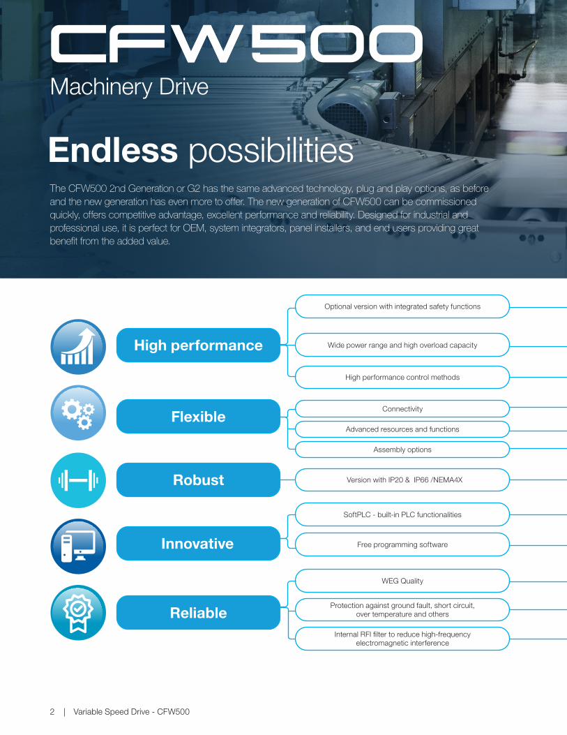
The CFW500 2nd Generation or G2 has the same advanced technology, plug and play options, as before and the new generation has even more to offer. The new generation of CFW500 can be commissioned quickly, offers competitive advantage, excellent performance and reliability. Designed for industrial and professional use, it is perfect for OEM, system integrators, panel installers, and end users providing great benefit from the added value.
Flexible
Robust
High performance Wide power range and high overload capacity
Assembly options
Version with IP20 & IP66 /NEMA4X
High performance control methods
Optional version with integrated safety functions
Connectivity
Endless possibilities
ReliableProtection against ground fault, short circuit,
over temperature and others
WEG Quality
Innovative
SoftPLC - built-in PLC functionalities
Free programming software
Advanced resources and functions
Internal RFI filter to reduce high-frequency electromagnetic interference

www.weg.net
Variable Speed Drive - CFW500 3
Integrated STO (Safe Torque Off) and SS1 (Safe Stop 1) fulfils requirements for safety performance SIL 3 / PL e, according to
IEC 61800-5-2, EN ISO 13849-1, EN 62061, IEC 61508 and IEC 60204-1
Provides machine builders a cost-effective solution to design protective measures to reduce the risk from unexpected and
hazardous movement in industrial machines
Surface or DIN rail mounting, including side-by-side installation
Pump Genius software
Complete protection against contact with internal live parts, avoiding the entrance of dust or water coming from jets
USB and fieldbus communication modules for the most used industrial networks, like CANopen, DeviceNet,
Profibus-DP, EtherNet/IP, PROFINET IO or Modbus-RTUFull integration with process network
Saves space and cabling, reducing installation costs
Dedicated functions ideal for pumping systems
The high protection degree dispenses the panel,reducing installation costs
Models from 1,0 to 105 A (0,25 kW / 0,33 HP to 55 kW / 75 HP) at supply voltages 200-240, 380-480 or 500-600 V
Sensorless or closed loop vector control, VVW or Scalar V/f and permanent magnet motor control: VVW PM
Permits the CFW500 to be used in a large variety of applications, improving their overall performance
100% of the VFDs are tested at the factory under full load and maximum temperature
It prevents damage to the inverter which can be caused by adverse situations, normally external factors.
Conformal Coating as standard, class 3C2 according to IEC 60721-3-3 and 3C3 as an option, to protect against corrosive
gases in harsh environments
The VFD, motor and application can work in an interactive way, because it is possible to make customized logic and applications.
Ideal for machinery manufacturer
High reliability
VFD lifetime is extended
WLP, WPS and SuperDrive G2 software available at www.weg.net
Certifications
www.weg.net
Frequency Inverter - CFW5004
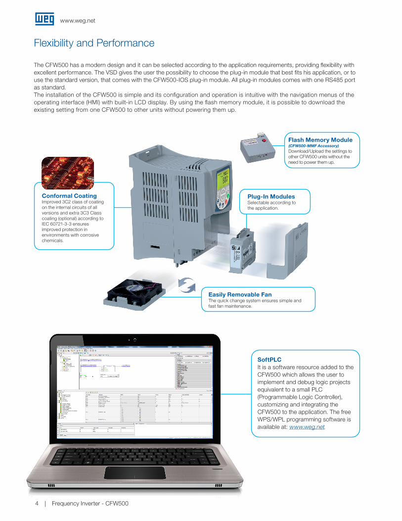
Flexibility and Performance
The CFW500 has a modern design and it can be selected according to the application requirements, providing flexibility with excellent performance. The VSD gives the user the possibility to choose the plug-in module that best fits his application, or to use the standard version, that comes with the CFW500-IOS plug-in module. All plug-in modules comes with one RS485 port as standard.The installation of the CFW500 is simple and its configuration and operation is intuitive with the navigation menus of the operating interface (HMI) with built-in LCD display. By using the flash memory module, it is possible to download the existing setting from one CFW500 to other units without powering them up.
Plug-In ModulesSelectable according to the application.
Easily Removable FanThe quick change system ensures simple and fast fan maintenance.
Flash Memory Module (CFW500-MMF Accessory) Download/Upload the settings to other CFW500 units without the need to power them up.
Conformal CoatingImproved 3C2 class of coating on the internal circuits of all versions and extra 3C3 Class coating (optional) according to IEC 60721-3-3 ensures improved protection in environments with corrosive chemicals.
SoftPLCIt is a software resource added to the CFW500 which allows the user to implement and debug logic projects equivalent to a small PLC (Programmable Logic Controller), customizing and integrating the CFW500 to the application. The free WPS/WPL programming software is available at: www.weg.net.

www.weg.net
Frequency Inverter - CFW500 5
Free at www.weg.net USB Connection (CFW500-CUSB accessory)
Easy operation and view
SuperDrive G2
I/O expansion:IOS (standard, included in the version with plug-in), IOD, IOAD, IOR
Functionality expansion:Incremental encoderUSB
Fieldbus communication protocols:CANopenDeviceNet RS232 RS485Profibus-DP EtherNet/IPModbus-TCP PROFINET IO
Selectable plug-in
modules
Remote operating interface (HMI)
(CFW500-HMIR accessory)
Connectivity
The CFW500 can be connected to the mainfast industrial Fieldbus communicationnetworks, with protocols used worldwidesuch as CANopen, Profibus-DP, DeviceNet, PROFINET IO, EtherNet/IP and Modbus-TCP, according to the plug-in module selected.
In addition, all plug-in modules come withserial interface RS485 Modbus-RTU built-in.
Using the SuperDrive G2 software, it is possible to change, monitor and view graphically the variables of the CFW500 on a personal computer.
Trend FunctionTrend charts for online monitoring of parameters and other variables within the SuperDrive G2 software.

www.weg.net
Frequency Inverter - CFW5006
Features
J Special engineering units (RPM, ºC, Nm, mA, %, kW, kWh, among others)
J Password to protect the parameters J Backup of all parameters (via SuperDrive G2 software, or plugin memory MMF)
J Possibility to save up to two different settings on the memory of the CFW500
J Setting of the switching frequency according to the application requirements
J Speed reference via electronic potentiometer J Multispeed with up to eight programmable speeds J Slip compensation J Manual or automatic torque boost (V/F scalar mode) or self-adjustment (VVW and vector modes)
J Permanent magnet motor control: VVW PM
J Acceleration/deceleration ramps J “S” type ramp J DC braking J Internal dynamic braking (except frame size A) J PID controller to control processes in closed loop J Flying start / Ride-through J Sleep mode J Skip frequencies or frequency ranges function adjustable J Overload and overtemperature protection J Overcurrent protection J DC link voltage supervision J Fault log J Safety functions: STO and SS1

www.weg.net
7
www.weg.net
J Display up to three variables at the same time,
selected by the user
Human-Machine Interface (keypad)
Friendly Programming J Oriented start-up: programming step by step J Easy and intuitive operation, fast access to the parameters J Parameter group: shortcut to the parameters of interest
CFW500 status
Main display
Soft keys
Bar forvariable monitoring
Secondary display
Unit of measurement
Parameter groups
Remote HMI (keypad)Suitable for enclosure door or machine console, two options available.
CFW500-CCHMIRXM X = up to 10 m
RS485 Included in all plug-in modules
CFW500-HMIRNon-Text Remote Keypad
Frequency Inverter - CFW500
HMI-01Advanced Text Remote Keypad
www.weg.net
Frequency Inverter - CFW5008
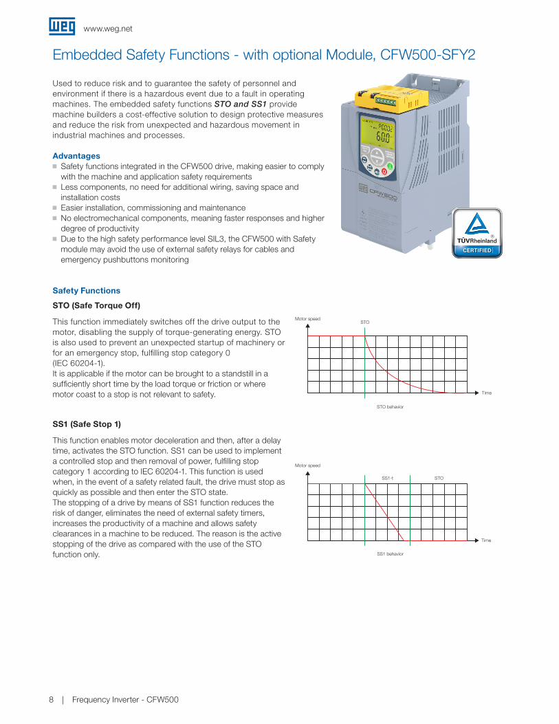
Embedded Safety Functions - with optional Module, CFW500-SFY2
Advantages
Safety Functions
STO (Safe Torque Off)
SS1 (Safe Stop 1)
Used to reduce risk and to guarantee the safety of personnel and environment if there is a hazardous event due to a fault in operating machines. The embedded safety functions STO and SS1 provide machine builders a cost-effective solution to design protective measures and reduce the risk from unexpected and hazardous movement in industrial machines and processes.
This function immediately switches off the drive output to the motor, disabling the supply of torque-generating energy. STO is also used to prevent an unexpected startup of machinery or for an emergency stop, fulfilling stop category 0 (IEC 60204-1).It is applicable if the motor can be brought to a standstill in a sufficiently short time by the load torque or friction or where motor coast to a stop is not relevant to safety.
This function enables motor deceleration and then, after a delay time, activates the STO function. SS1 can be used to implement a controlled stop and then removal of power, fulfilling stop category 1 according to IEC 60204-1. This function is used when, in the event of a safety related fault, the drive must stop as quickly as possible and then enter the STO state. The stopping of a drive by means of SS1 function reduces the risk of danger, eliminates the need of external safety timers, increases the productivity of a machine and allows safety clearances in a machine to be reduced. The reason is the active stopping of the drive as compared with the use of the STO function only.
J Safety functions integrated in the CFW500 drive, making easier to comply with the machine and application safety requirements
J Less components, no need for additional wiring, saving space and installation costs
J Easier installation, commissioning and maintenance J No electromechanical components, meaning faster responses and higher degree of productivity
J Due to the high safety performance level SIL3, the CFW500 with Safety module may avoid the use of external safety relays for cables and emergency pushbuttons monitoring
Motor speed
Time
STO
Motor speed
Time
SS1-t STO
Motor speed
Time
STO
Motor speed
Time
SS1-t STO
Motor speed
Time
STO behavior
SS1 behavior
Time
STO
STOSS1-t
Motor speed
www.weg.net
Frequency Inverter - CFW500 9
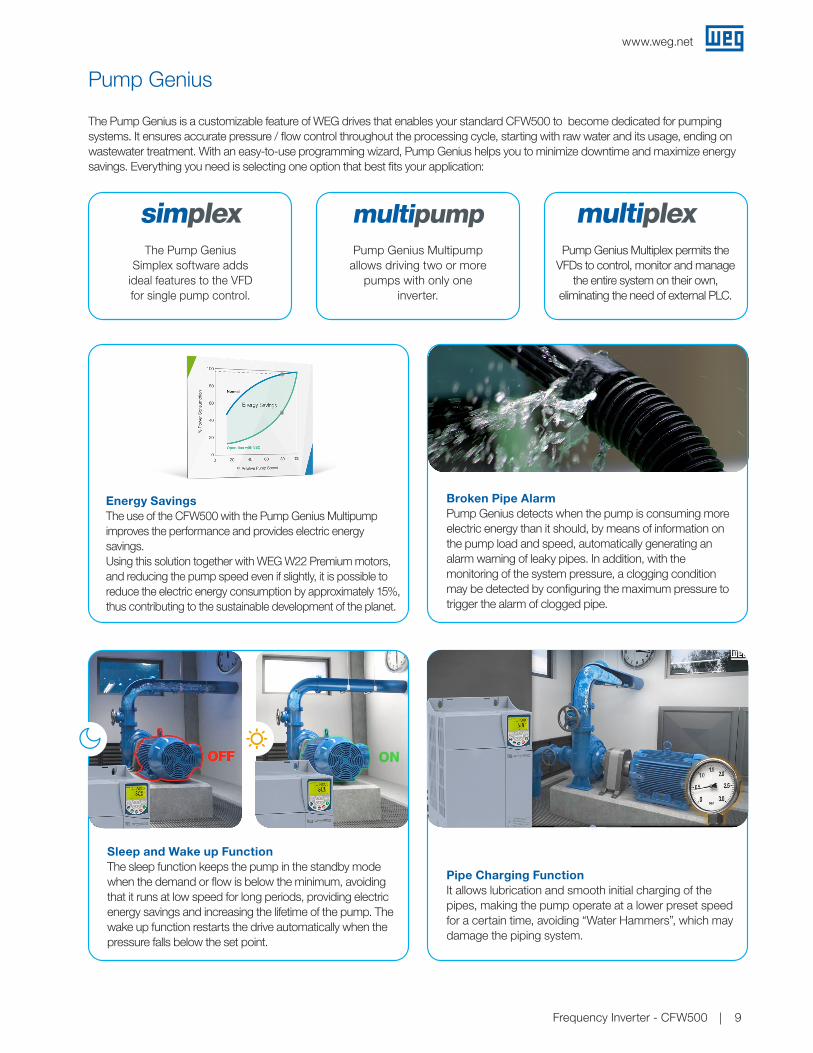
Pump Genius
Pump Genius Multipump allows driving two or more
pumps with only one inverter.
Energy SavingsThe use of the CFW500 with the Pump Genius Multipump improves the performance and provides electric energy savings.Using this solution together with WEG W22 Premium motors, and reducing the pump speed even if slightly, it is possible to reduce the electric energy consumption by approximately 15%, thus contributing to the sustainable development of the planet.
Sleep and Wake up FunctionThe sleep function keeps the pump in the standby mode when the demand or flow is below the minimum, avoiding that it runs at low speed for long periods, providing electric energy savings and increasing the lifetime of the pump. The wake up function restarts the drive automatically when the pressure falls below the set point.
Pipe Charging Function It allows lubrication and smooth initial charging of the pipes, making the pump operate at a lower preset speed for a certain time, avoiding “Water Hammers”, which may damage the piping system.
Broken Pipe AlarmPump Genius detects when the pump is consuming more electric energy than it should, by means of information on the pump load and speed, automatically generating an alarm warning of leaky pipes. In addition, with the monitoring of the system pressure, a clogging condition may be detected by configuring the maximum pressure to trigger the alarm of clogged pipe.
The Pump Genius is a customizable feature of WEG drives that enables your standard CFW500 to become dedicated for pumping systems. It ensures accurate pressure / flow control throughout the processing cycle, starting with raw water and its usage, ending on wastewater treatment. With an easy-to-use programming wizard, Pump Genius helps you to minimize downtime and maximize energy savings. Everything you need is selecting one option that best fits your application:
multipumpPump Genius Multiplex permits the
VFDs to control, monitor and manage the entire system on their own,
eliminating the need of external PLC.
multiplexThe Pump Genius
Simplex software adds ideal features to the VFD for single pump control.
simplex
www.weg.net
Frequency Inverter - CFW50010
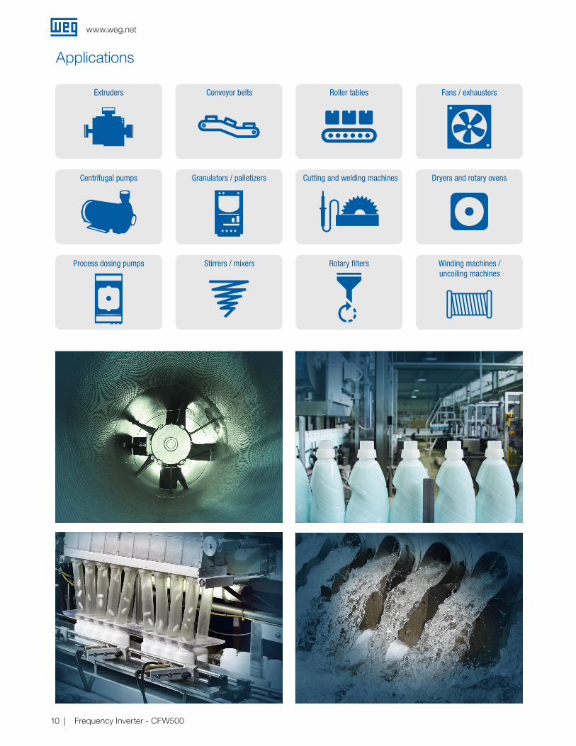
Applications
Extruders
Centrifugal pumps
Process dosing pumps
Conveyor belts
Granulators / palletizers
Stirrers / mixers
Roller tables
Cutting and welding machines
Rotary filters
Fans / exhausters
Dryers and rotary ovens
Winding machines / uncoiling machines
www.weg.net
Frequency Inverter - CFW500 11
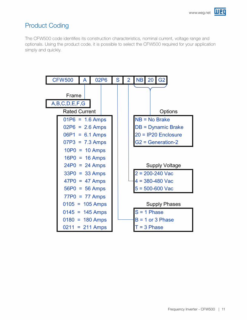
Product Coding
The CFW500 code identifies its construction characteristics, nominal current, voltage range and optionals. Using the product code, it is possible to select the CFW500 required for your application simply and quickly.
CFW500-IP20-G2 Tables for Brochure-R1
A S 2 NB 20 G2
DB = Dynamic Brake20 = IP20 EnclosureG2 = Generation-2
2 = 200-240 Vac4 = 380-480 Vac5 = 500-600 Vac
S = 1 PhaseB = 1 or 3 PhaseT = 3 Phase
0145 = 145 Amps0180 = 180 Amps0211 = 211 Amps
56P0 = 56 Amps77P0 = 77 Amps
Supply Phases
24P0 = 24 Amps33P0 = 33 Amps47P0 = 47 Amps
06P1 = 6.1 Amps07P3 = 7.3 Amps10P0 = 10 Amps16P0 = 16 Amps
Supply Voltage
0105 = 105 Amps
02P6 = 2.6 Amps
CFW500 02P6
Frame
OptionsNB = No Brake
A,B,C,D,E,F,GRated Current01P6 = 1.6 Amps
Page 1 CFW500 Catalog Seq.

www.weg.net
Frequency Inverter - CFW50012
3 Phase / 230VAC Motor VoltageND / VT 1 HD / CT 1
Catalog Number
Braking Transistor
Frame Size 4
Dimensions (in.) HxWxD
Approx. Weight (lbs.)Motor HP 2 Drive Amps 3 Motor HP 2 Drive Amps 3
Input power supply: Single-Phase 200 - 240 V 1/3 1.6 1/3 1.6 CFW500A01P6S2NB20G2 No A 7.5 x 3.0 x 5.9 1.8 3/4 2.6 3/4 2.6 CFW500A02P6S2NB20G2 No A 7.5 x 3.0 x 5.9 1.81 1/2 4.3 1 1/2 4.3 CFW500A04P3S2NB20G2 No A 7.5 x 3.0 x 5.9 1.8
2 7.3 2 7.3 CFW500A07P0S2NB20G2 No A 7.5 x 3.0 x 5.9 1.8Input power supply: Single or Three-Phase 200 - 240 V
1/3 1.6 1/3 1.6 CFW500A01P6B2NB20G2 No A 7.5 x 3.0 x 5.9 1.8 3/4 2.6 3/4 2.6 CFW500A02P6B2NB20G2 No A 7.5 x 3.0 x 5.9 1.81 1/2 4.3 1 1/2 4.3 CFW500A04P3B2NB20G2 No A 7.5 x 3.0 x 5.9 1.8
2 7.3 2 7.3 CFW500B07P3B2DB20G2 Yes B 7.9 x 4.0 x 6.3 2.63 10.0 3 10.0 CFW500B10P0B2DB20G2 Yes B 7.9 x 4.0 x 6.3 2.6
Input power supply: Three-phase 200 - 240 V2 7.0 2 7.0 CFW500A07P0T2NB20G2 No A 7.5 x 3.0 x 5.9 1.83 9.6 3 9.6 CFW500A09P6T2NB20G2 No A 7.5 x 3.0 x 5.9 1.85 16 5 16 CFW500B16P0T2DB20G2 Yes B 7.9 x 4.0 x 6.3 2.6
7 1/2 24 7 1/2 24 CFW500C24P0T2DB20G2 Yes C 8.3 x 5.3 x 6.5 4.410 28 10 28 CFW500D28P0T2DB20G2 Yes D 12.1 x 7.1 x 6.6 9.510 33 10 33 CFW500D33P0T2DB20G2 Yes D 12.1 x 7.1 x 6.6 9.515 47 15 47 CFW500D47P0T2DB20G2 Yes D 12.1 x 7.1 x 6.6 9.520 56 20 56 CFW500E56P0T2DB20G2 Yes E 13.8 x 8.7 x 7.6 22.125 77 20 64 CFW500F77P0T2DB20G2 Yes F 21.6 x 11.8 x 10 57.330 88 25 75 CFW500F88P0T2DB20G2 Yes F 21.6 x 11.8 x 10 57.340 105 30 88 CFW500F0105T2DB20G2 Yes F 21.6 x 11.8 x 10 57.350 145 40 115 CFW500G0145T2NB20G2 No G 26.6 x 13.2 x 12.4 114.660 180 50 145 CFW500G0180T2NB20G2 No G 26.6 x 13.2 x 12.4 114.675 211 60 180 CFW500G0211T2NB20G2 No G 26.6 x 13.2 x 12.4 114.650 145 40 115 CFW500G0145T2DB20G2 Yes G 26.6 x 13.2 x 12.4 114.660 180 50 145 CFW500G0180T2DB20G2 Yes G 26.6 x 13.2 x 12.4 114.675 211 60 180 CFW500G0211T2DB20G2 Yes G 26.6 x 13.2 x 12.4 114.6
Notes:1) ND (Normal Duty) / VT (Variable Torque): 110% Overload / 60 Sec; HD (Heavy Duty) / CT (Constant Torque): 150% Overload / 60 Sec; 2) “HP” rating based on WEG W22 motors “average FLA values”. Use as a guide only.3) Motor FLA may vary with speed and manufacturer. ALWAYS compare motor FLA to Nominal AMPS of drive.4) Frame Size A to E are rated for 50°C; Frame Size-F is rated for 40°C; Frame Size-G is rated for 45°C. CFW500 Frame-F & G VFDs have built in Dual DC bus chokes.
CFW500-IP20-G2 Drives Rating
The correct way to select a VFD is matching its output current with the motor rated current. However, the tables below present the approximate motor power for each VFD model. Use the motor power ratings below only as a guide. Motor rated currents may vary with speed and manufacturer.

www.weg.net
Frequency Inverter - CFW500 13
www.weg.net
Frequency Inverter - CFW50013
CFW500-IP20-G2 Drives RatingThe correct way to select a VFD is matching its output current with the motor rated current. However, the tables below present the approximate motor power for each VFD model. Use the motor power ratings below only as a guide. Motor rated currents may vary with speed and manufacturer.
3 Phase / 460VAC Motor VoltageND / VT1 HD / CT 1
Catalog Number
Braking Transistor
Frame Size 4Dimensions (in.)
HxWxDApprox. Weight (lbs.)
Motor HP 2 Drive Amps 3 Motor HP 2 Drive Amps 3
Input Power Supply: Three-Phase 380-480 Vac 1/2 1.0 1/2 1.0 CFW500A01P0T4NB20G2 No A 7.5 x 3.0 x 5.9 1.8
1 1.6 1 1.6 CFW500A01P6T4NB20G2 No A 7.5 x 3.0 x 5.9 1.8
2 2.6 2 2.6 CFW500A02P6T4NB20G2 No A 7.5 x 3.0 x 5.9 1.8
3 4.3 3 4.3 CFW500A04P3T4NB20G2 No A 7.5 x 3.0 x 5.9 1.8
3 6.1 3 6.1 CFW500A06P1T4NB20G2 No A 7.5 x 3.0 x 5.9 1.8
2 2.6 2 2.6 CFW500B02P6T4DB20G2 Yes B 7.9 x 4.0 x 6.3 2.6
3 4.3 3 4.3 CFW500B04P3T4DB20G2 Yes B 7.9 x 4.0 x 6.3 2.6
5 6.5 5 6.5 CFW500B06P5T4DB20G2 Yes B 7.9 x 4.0 x 6.3 2.6
7 1/2 10 7 1/2 10 CFW500B10P0T4DB20G2 Yes B 7.9 x 4.0 x 6.3 2.6
10 14 10 14 CFW500C14P0T4DB20G2 Yes C 8.3 x 5.3 x 6.5 4.4
10 16 10 16 CFW500C16P0T4DB20G2 Yes C 8.3 x 5.3 x 6.5 4.4
15 24 15 24 CFW500D24P0T4DB20G2 Yes D 12.1 x 7.1 x 6.6 9.5
25 31 25 31 CFW500D31P0T4DB20G2 Yes D 12.1 x 7.1 x 6.6 9.5
30 39 30 39 CFW500E39P0T4DB20G2 Yes E 13.8 x 8.7 x 7.6 22.1
40 49 40 49 CFW500E49P0T4DB20G2 Yes E 13.8 x 8.7 x 7.6 22.1
60 77 50 61 CFW500F77P0T4DB20G2 Yes F 21.6 x 11.8 x 10 57.3
75 88 60 73 CFW500F88P0T4DB20G2 Yes F 21.6 x 11.8 x 10 57.3
75 105 75 88 CFW500F0105T4DB20G2 Yes F 21.6 x 11.8 x 10 57.3
125 142 100 115 CFW500G0142T4NB20G2 No G 26.6 x 13.2 x 12.4 114.6
150 180 125 142 CFW500G0180T4NB20G2 No G 26.6 x 13.2 x 12.4 114.6
175 211 150 180 CFW500G0211T4NB20G2 No G 26.6 x 13.2 x 12.4 114.6
125 142 100 115 CFW500G0142T4DB20G2 Yes G 26.6 x 13.2 x 12.4 114.6
150 180 125 142 CFW500G0180T4DB20G2 Yes G 26.6 x 13.2 x 12.4 114.6
175 211 150 180 CFW500G0211T4DB20G2 Yes G 26.6 x 13.2 x 12.4 114.6
3 Phase / 575VAC Motor Voltage 5
ND / VT1 HD / CT 1 Catalog Number
Braking Transistor
Frame Size 4Dimensions (in.)
HxWxDApprox. Weight (lbs.)
Motor HP 2 Drive Amps 3 Motor HP 2 Drive Amps 3
Input Power Supply: Three-Phase 500-600 Vac1 1/2 1.7 1 1/2 1.7 CFW500C01P7T5DB20 Yes C 8.3 x 5.3 x 6.5 4.4
3 3.0 3 3.0 CFW500C03P0T5DB20 Yes C 8.3 x 5.3 x 6.5 4.4
3 4.3 3 4.3 CFW500C04P3T5DB20 Yes C 8.3 x 5.3 x 6.5 4.4
7 1/2 7.0 7 1/2 7.0 CFW500C07P0T5DB20 Yes C 8.3 x 5.3 x 6.5 4.4
10 10.0 10 10.0 CFW500C10P0T5DB20 Yes C 8.3 x 5.3 x 6.5 4.4
10 12.0 10 12.0 CFW500C12P0T5DB20 Yes C 8.3 x 5.3 x 6.5 4.4
Notes:
1) ND (Normal Duty) / VT (Variable Torque): 110% Overload / 60 Sec;
HD (Heavy Duty) / CT (Constant Torque): 150% Overload / 60 Sec;
2) “HP” rating based on WEG W22 motors “average FLA values”. Use as a guide only.
3) Motor FLA may vary with speed and manufacturer. ALWAYS compare motor FLA to Nominal AMPS of drive.
4) Frame Size A to E are rated for 50°C; Frame Size-F is rated for 40°C; Frame Size-G is rated for 45°C.
CFW500 Frame-F & G VFDs have built in Dual DC bus chokes.
5) All 575V drives are non-stocked items and are still Generation-1 drives, consult WEG for availability.
3 Phase / 575VAC Motor Voltage

www.weg.net
Frequency Inverter - CFW50014
Plug-In Module
Note: 1) Accessory included in the CFW500. Plug in modules can be sold separately as an accessory or spare part.
ReferenceDescription
Illustrative figuresInput and output (I/O) expansion
CFW500-IOS1) Standard plug-in module (included in the version with plug-in module)
CFW500-IOD Digital input and output (I/O) expansion plug-in module
CFW500-IOAD Digital and analog input and output (I/O) expansion plug-in module
CFW500-IOR-B Relay output expansion plug-in module
Reference Functionality expansion
CFW500-SFY2CFW500 Safety Function Module; Safe Torque Off (STO) / Stop Category 0, Safe Stop 1 Time Controlled (SS1-t) / Sop Category 1; Safety
Category: SIL 3, PL e
CFW500-ENC Plug-in module with encoder input
CFW500-CUSB Plug-in module with USB port
Reference Communication on Fieldbus network
CFW500-CCAN CAN communication plug-in module (CANopen/DeviceNet)
CFW500-CRS232 RS232 communication plug-in module
CFW500-CRS485-B RS485 communication plug-in module
CFW500-CPDP Profibus-DP communication plug-in module
CFW500-CETH-IP EtherNet/IP communication plug-in module
CFW500-CEMB-TCP Modbus-TCP communication plug-in module
CFW500-CEPN-IO PROFINET IO communication plug-in module
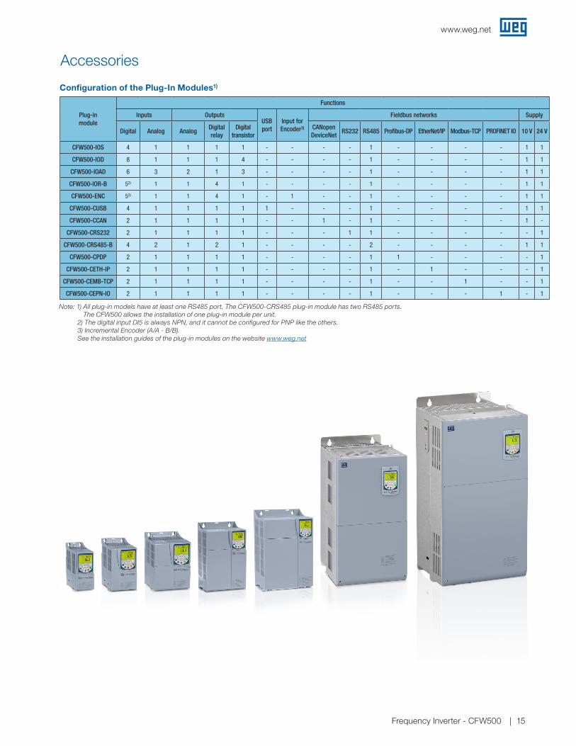
The CFW500 comes with the IOS module included. Other modules are available to expand the inputs or outputs available as noted in the table below. Communication modules can be selected based on the monitoring or control network in use. RS-485 is included on the CFW500 as standard.
Accessories
Reference Memory Illustrative figures
CFW500-MMF Flash memory module
Reference Interfaces
CFW500-HMIR Remote operating interface (HMI)
HMI-01 CFW500 Remote Advanced Text Keypad for mounting through enclosure door (Mounting Frame Kit is required)
CFW500-RHMIF CFW500 Remote Advanced Text Keypad enclosure door mounting frame kit
CFW500-CCHMIR1M 1-meter cable set for remote operating interface (HMI)
CFW500-CCHMIR2M 2-meter cable set for remote operating interface (HMI)
CFW500-CCHMIR3M 3-meter cable set for remote operating interface (HMI)
CFW500-CCHMIR5M 5-meter cable set for remote operating interface (HMI)
CFW500-CCHMIR75M 7.5-meter cable set for remote operating interface (HMI)
CFW500-CCHMIR10M 10-meter cable set for remote operating interface (HMI)
Reference Description
CFW500-KN1A NEMA 1 Kit - size A (standard for option N1)
CFW500-KN1B NEMA 1 Kit - size B (standard for option N1)
CFW500-KN1C NEMA 1 Kit - size C (standard for option N1)
CFW500-KN1D NEMA 1 Kit - size D (standard for option N1)
CFW500-KN1E NEMA 1 Kit - size E (standard for option N1)
CFW500-KN1F NEMA 1 Kit - size F (standard for option N1)
CFW500-KN1G NEMA 1 Kit - size G (standard for option N1)
CFW500-KPCSA Shielding kit for the power cables - size A
CFW500-KPCSB Shielding kit for the power cables - size B
CFW500-KPCSC Shielding kit for the power cables - size C
CFW500-KPCSD Shielding kit for the power cables - size D
CFW500-KPCSE Shielding kit for the power cables - size E
CFW500-KPCSF Shielding kit for the power cables - size F
CFW500-KPCSG Shielding kit for the power cables - size G
www.weg.net
Frequency Inverter - CFW500 15
Accessories
Configuration of the Plug-In Modules1)
Plug-in module
Functions
Inputs OutputsUSB port
Input for Encoder3)
Fieldbus networks Supply
Digital Analog AnalogDigital relay
Digital transistor
CANopenDeviceNet
RS232 RS485 Profibus-DP EtherNet/IP Modbus-TCP PROFINET IO 10 V 24 V
CFW500-IOS 4 1 1 1 1 - - - - 1 - - - - 1 1
CFW500-IOD 8 1 1 1 4 - - - - 1 - - - - 1 1
CFW500-IOAD 6 3 2 1 3 - - - - 1 - - - - 1 1
CFW500-IOR-B 52) 1 1 4 1 - - - - 1 - - - - 1 1
CFW500-ENC 52) 1 1 4 1 - 1 - - 1 - - - - 1 1
CFW500-CUSB 4 1 1 1 1 1 - - - 1 - - - - 1 1
CFW500-CCAN 2 1 1 1 1 - - 1 - 1 - - - - 1 -
CFW500-CRS232 2 1 1 1 1 - - - 1 1 - - - - - 1
CFW500-CRS485-B 4 2 1 2 1 - - - - 2 - - - - 1 1
CFW500-CPDP 2 1 1 1 1 - - - - 1 1 - - - - 1
CFW500-CETH-IP 2 1 1 1 1 - - - - 1 - 1 - - - 1
CFW500-CEMB-TCP 2 1 1 1 1 - - - - 1 - - 1 - - 1
CFW500-CEPN-IO 2 1 1 1 1 - - - - 1 - - - 1 - 1
Note: 1) All plug-in models have at least one RS485 port. The CFW500-CRS485 plug-in module has two RS485 ports. The CFW500 allows the installation of one plug-in module per unit.
2) The digital input DI5 is always NPN, and it cannot be configured for PNP like the others. 3) Incremental Encoder (A/A - B/B). See the installation guides of the plug-in modules on the website www.weg.net

www.weg.net
Frequency Inverter - CFW50016
NEMA1 Version
Frame size NEMA1
Height in. (mm)
Width in. (mm)
Depth in. (mm)
Weight lbs. (kg)
A 8.8 (223.0) 3.0 (75.2) 5.9 (149.5) 2.4 (1.1)
B 9.6 (243.3) 3.9 (100.2) 6.3 (160.1) 3.3 (1.5)
C 10.0 (254.8) 5.3 (135.2) 6.5 (165.1) 5.3 (2.4)
D 14.3 (361.9) 7.1 (180.0) 6.6 (166.4) 10.2 (4.6)
E 16.0 (405.7) 8.7 (220.0) 7.5 (191.4) 22.5 (10.4)
F 27.22 (691.4) 11.81 (300) 10.20 (259.2) 60.3 (27.3)
G 27.22 (691.4) 13.2 (335.3) 12.36 (314) 117.2 (53.16)
D
W
H
Dimensions and Weights
IP20 Version
SizeA B C D H L P Weight
In (mm) In (mm) In (mm) In (mm) In (mm) In (mm) In (mm) lb (kg)
A 1.97 (50.0) 6.89 (175.0) 0.47 (11.9) 0.28 (7.2) 7.44 (189.0) 2.95 (75.0) 5.91 (150.0) 1.76 (0.8)
B 2.95 (75.0) 7.30 (185.0) 0.46 (11.8) 0.29 (7.3) 7.83 (199.0) 3.94 (100.0) 6.30 (160.0) 2.65 (1.2)
C 3.94 (100.0) 7.70 (195.0) 0.66 (16.7) 0.23 (5.8) 8.27 (210.0) 5.31 (135.0) 6.50 (165.0) 4.4 (2)
D 4.92 (125.0) 11.41 (290.0) 1.08 (27.5) 0.40 (10.2) 12.07 (306.6) 7.08 (180.0) 6.55 (166.5) 9.48 (4.3)
E 5.90 (150.0) 12.99 (330.0) 1.34 (34.0) 0.41 (10.6) 13.77 (350.0) 8.66 (220.0) 7.53 (191.5) 22.05 (10)
F 7.87 (200.0) 20.67 (525.0) 1.67 (42.5) 0.59 (15.0) 21.65 (550.0) 11.81 (300.0) 10 (254.0) 57.3 (26)
G 7.87 (200.0) 25.59 (650.0) 2.24 (57.0) 0.59 (15.0) 26.57 (675.0) 13.2 (335.3) 12.36 (314) 114.64 (52)
Front view Side view
L
AD
H B
C
P

www.weg.net
Frequency Inverter - CFW500 17
Standards
Standards
Safety standards
UL 508C - Power conversion equipment
UL 840 - Insulation coordination including clearances and creepage distances for electrical equipment
EN 61800-5-1 - Safety requirements electrical, thermal and energy
EN 50178 - Electronic equipment for use in power installations
EN 60204-1 - Safety of machinery. Electrical equipment of machines. Part 1: general requirementsNote: In order to have a machine in accordance with this standard, the manufacturer of the machine is responsible for installing an emergency stop device and a device for disconnection from the power line
EN 60146 (IEC 146) - Semiconductor converters
EN 61800-2 - Adjustable speed electrical power drive systems - Part 2: general requirements - Rating specifications for low voltage adjustable frequency AC power drive systems
Electromagnetic compatibility
standards
EN 61800-3 - Adjustable speed electrical power drive systems - Part 3: EMC product standard including specific test methods
EN 55011 - Limits and methods of measurement of radio disturbance characteristcs of industrial, scientific and medical (ISM) radio-frequency equipment
CISPR 11 - Industrial, scientific and medical (ISM) radio-frequency equipment - Electromagnetic disturbance characteristics - Limits and methods of measurement
EN 61000-4-2 - Electromagnetic compatibility (EMC) - Part 4: testing and measurement techniques - Section 2: electrostatic discharge immunity test
EN 61000-4-3 - Electromagnetic compatibility - Part 4: testing and measurement techniques - Section 3: ratiated, radio-frequency, electromagnetic field immunity test
EN 61000-4-4 - Electromagnetic compatibility - Part 4: testing and measurement techniques - Section 4: electrical fast transient/burst immunity test
EN 61000-4-5 - Electromagnetic compatibility - Part 4: testing and measurement techniques - Section 5: surge immunity test
EN 61000-4-6 - Electromagnetic compatibility - Part 4: testing and measurement techniques - Section 6: immunity to conducted disturbances, induced by radio-frequency fields
Mechanical construction
standards
EN 60529 - Degrees of protection provided by enclosures (IP code)
UL 50 - Enclosures for electrical equipment
IEC60721-3-3 - Classification of environmental conditions - part 3: classification of groups of environmental parameters and their severities - Section 3: stationary use at weather protected locations level 3M4.

www.weg.net
Frequency Inverter - CFW50018
Technical Specifications
Notes: 1) The number and/or types of analog/digital inputs/outputs may vary according to the plug-in module (accessory) used. In the table above, the standard plug-in module (CFW500-IOS) was taken into account. For further information, refer to the CFW500 user manual.
2) The maximum capacity of 150 mA considers the load of the 24 V power supply plus the transistor output, that is, the sum of the consumption of both must not exceed 150 mA.
Power rating Power supply
Tolerance: -15 to +10%Frequency: 50/60 Hz (48 Hz to 62 Hz)Phase imbalance: ≤3% of the rated phase-phase input voltageTransient voltages and overvoltages according to Category III (EN 61010/UL 508C)Maximum of 10 (line) connections per hour (1 every 6 minutes)Typical efficiency: ≥97%
ControlMethod
V/F (scalar)VVW: voltage vector controlVector without encoder (sensorless) and closed loop vector with encoder PM VVW: voltage vector control for permanent magnet motors
Output frequency 0 to 500 Hz, resolution of 0.015 Hz
Performance
V/F ControlSpeed regulation: 1% of the rated speed (with slip compensation) Speed variation range: 1:20
Vector control (VVW)Speed regulation: 1% of the rated speed Speed variation range: 1:30
SensorlessSpeed regulation: 0.5% of the rated speed Speed variation range: 1:100
Vector control with EncoderSpeed regulation: 0.1% of the rated speed Speed variation range: 1:100
PM VVW ControlRegulation: 0.1 % of the rated speedSpeed variation range: 1:20
Environment conditions
Temperature around the CFW500
-10 °C to 50 °C - IP20 (sizes A to E) -10 °C to 40 °C - IP20 (sizes A to E) when installed by side -10 °C to 40 °C - NEMA 1 (sizes A to E)-10 °C to 40 °C - IP20, NEMA 1 (size F) -10 °C to 45 °C - IP20, NEMA 1 (size G) For sizes A to E, when operating temperatures are above the specification, it is necessary to apply 2% of current derating for each Celsius degree (ºC), limited to an increase of 10 °C.For size F and G, when operating temperatures are above the specification, it is necessary to apply 1% of current derating for each Celsius degree (°C) up to 50 °C, and 2% up to 60 °C (maximum).
Aggressive environmentsProtection Class 3C2 - Standard coating on the internal circuits, according to IEC 60721-3-3 (standard model)Protection Class 3C3 - Extra coating - optional, according to IEC 60721-3-3 (optional)
Air relative humidity 5% to 95% non-condensing
Altitude Up to 1,000 m (maximum altitude under normal conditions)1,000 to 4,000 m: current derating of 1% for each 100 m above 1,000 m of altitude
Pollution degree2 (EN 50178 and UL 508C), with non-conductive pollutionCondensation must not cause conduction of the accumulated residues
Inputs1)
Analog
1 isolated input. Levels: (0 to 10) V or (0 to 20) mA or (4 to 20) mA Linearity error ≤0.25%Impedance: 100 kΩ for voltage input, 500 Ω for current input Programmable functions, including PTC inputMaximum voltage accepted in the inputs: 30 V dc
Digital
4 isolated inputs Programmable functions:Active high (PNP): maximum low level of 15 V dc; minimum high level of 20 V dcActive low (NPN): maximum low level of 5 V dc; minimum high level of 9 V dc Maximum input voltage of 30 V dcInput current: 4.5 mA Maximum input current: 5.5 mA
Outputs1)
Analog
1 isolated output. Levels (0 to 10) V or (0 to 20) mA or (4 to 20) mA Linearity error ≤0.25%Programmable functionsRL ≥10 kΩ (0 to 10 V) or RL ≤500 Ω (0 to 20 mA / 4 to 20 mA)
Relay
1 relay with NO/NC contact Maximum voltage: 240 V ac Maximum current of 0.5 A Programmable functions
Transistor1 isolated open sink digital output (using as reference the 24 V dc power supply) Maximum current of 150 mA (maximum capacity of the 24 V dc power supply)2)
Programmable functions
Power supply
24 V dc power supply. Maximum capacity: 150 mA2)
Power supply of 10 V dc. Maximum capacity: 2 mA
Communication Selectable plug-inFieldbus: Modbus-RTU, CANopen, DeviceNet, Profibus-DP, EtherNet/IP, Modbus-TCP, PROFINET IOUSB, RS485 and RS232 ports
Safety Protection
Phase-phase overcurrent/short circuit in the output Phase-ground overcurrent/short circuit in the output Undervoltage/overvoltage in the power Overtemperature of the heatsinkMotor overloadOverload on the power module (IGBTs) External fault / alarmProgramming error
Operating interface (keypad)Standard
(built in the CFW500)
9 keys: Run/Stop, Increment, Decrement, Direction of rotation, Jog, Local/Remote, Back/Esc and Enter/MenuLCD DisplayIt allows accessing/changing all the parameters Accuracy of the indications:Current: 5% of the rated current Speed resolution: 0.1 Hz
Protection degree IP20 Sizes A, B, C, D, E, F and G
NEMA1 Sizes A, B, C, D, E, F and G with NEMA1 kit

www.weg.net
Frequency Inverter - CFW500 19
Block Diagram of CFW500-IP20 or NEMA1 Version
Notes: 1) The number of inputs and outputs (analog and digital), as well as other resources, may vary according to the plug-in module used. For further information, refer to the CFW500 user manual.
2) Not available for size A. 3) Connection available for sizes D and E only. Inductor on the DC link not included. Sizes F and G have DC link inductor built-in as standard, to protect the drive against current spikes. 4) Resistor not included. Internal dynamic braking (IGBT) built-in the whole line, except for frame size A of IP20 / NEMA1 version.
PE
PE
21 1
1+UD -UDBR
CONTROL
Remote operating interface (HMI)
Operating interface (HMI)
CPU32 bits‘‘RISC’’
EEPROM(memory)
24 V power supply
DO2 digitaloutput (TR)1)
DO1 digitaloutput (RL1)
Memory card (CFW500-MMF)
accessory
RS48510 V power supply
Interfaces(RS232,
RS485 or USB)
WLP softwareSuperDrive
G2
Modbus-RTU
Digital inputs(DI1 to DI4)1)
Analog inputs(AI1)1)
CFW500-IOS1)
POWER
12
= DC link connection
Connection of external inductor in the DC link3) Braking resistor4)
= Connection for braking resistor2)
Power supply
R/L1/L
S/L2/N
T/L3
U/T1
V/T2
W/T3Motor
Voltage and currentfeedback
Three-phase/single-phase rectifier
DC li
nk c
apac
itor b
ank
Brak
ing
IGBT
Internal RFI
Filter
PLUG-IN
Pre-charge
Inverter with IGBT transistors
Power supplies for electronics and interfaces between power and control
Plug-in module
Analogoutput (AO1)1)
US
.CFW
500.
IP20
.Rev
: 01
|6.2
021.
5010
9053
The
valu
es s
how
n ar
e su
bje
ct to
cha
nge
with
out p
rior
notic
e.
WEG Electric Corp. 6655 Sugarloaf Parkway Duluth, GA 30097 Phone: 1-800-ASK-4WEG www.weg.net
Please contact your authorized distributor:
www.weg.net
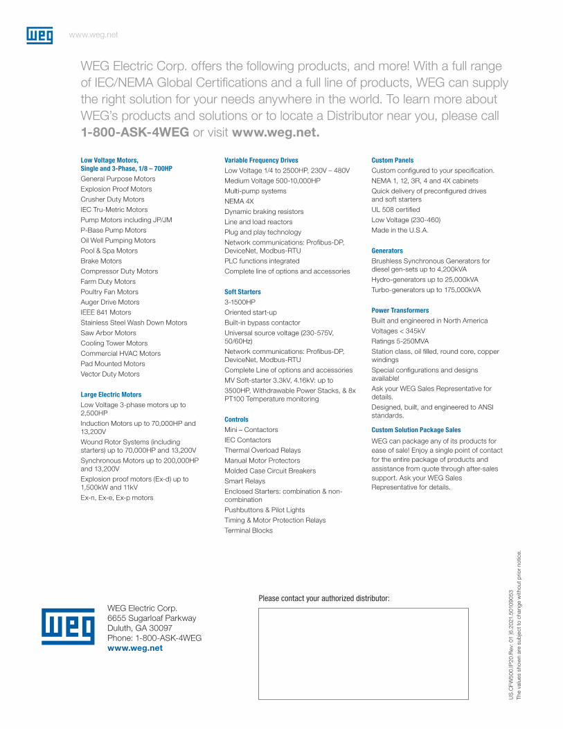
WEG Electric Corp. offers the following products, and more! With a full range of IEC/NEMA Global Certifications and a full line of products, WEG can supply the right solution for your needs anywhere in the world. To learn more about WEG’s products and solutions or to locate a Distributor near you, please call 1-800-ASK-4WEG or visit www.weg.net.
Low Voltage Motors, Single and 3-Phase, 1/8 – 700HP
General Purpose Motors
Explosion Proof Motors
Crusher Duty Motors
IEC Tru-Metric Motors
Pump Motors including JP/JM
P-Base Pump Motors
Oil Well Pumping Motors
Pool & Spa Motors
Brake Motors
Compressor Duty Motors
Farm Duty Motors
Poultry Fan Motors
Auger Drive Motors
IEEE 841 Motors
Stainless Steel Wash Down Motors
Saw Arbor Motors
Cooling Tower Motors
Commercial HVAC Motors
Pad Mounted Motors
Vector Duty Motors
Large Electric Motors
Low Voltage 3-phase motors up to 2,500HP
Induction Motors up to 70,000HP and 13,200V
Wound Rotor Systems (including starters) up to 70,000HP and 13,200V
Synchronous Motors up to 200,000HP and 13,200V
Explosion proof motors (Ex-d) up to 1,500kW and 11kV
Ex-n, Ex-e, Ex-p motors
Variable Frequency Drives
Low Voltage 1/4 to 2500HP, 230V – 480V
Medium Voltage 500-10,000HP
Multi-pump systems
NEMA 4X
Dynamic braking resistors
Line and load reactors
Plug and play technology
Network communications: Profibus-DP, DeviceNet, Modbus-RTU
PLC functions integrated
Complete line of options and accessories
Soft Starters
3-1500HP
Oriented start-up
Built-in bypass contactor
Universal source voltage (230-575V, 50/60Hz)
Network communications: Profibus-DP, DeviceNet, Modbus-RTU
Complete Line of options and accessories
MV Soft-starter 3.3kV, 4.16kV: up to
3500HP, Withdrawable Power Stacks, & 8x PT100 Temperature monitoring
Controls
Mini – Contactors
IEC Contactors
Thermal Overload Relays
Manual Motor Protectors
Molded Case Circuit Breakers
Smart Relays
Enclosed Starters: combination & non-combination
Pushbuttons & Pilot Lights
Timing & Motor Protection Relays
Terminal Blocks
Custom Panels
Custom configured to your specification.
NEMA 1, 12, 3R, 4 and 4X cabinets
Quick delivery of preconfigured drivesand soft starters
UL 508 certified
Low Voltage (230-460)
Made in the U.S.A.
Generators
Brushless Synchronous Generators for diesel gen-sets up to 4,200kVA
Hydro-generators up to 25,000kVA
Turbo-generators up to 175,000kVA
Power Transformers
Built and engineered in North America
Voltages < 345kV
Ratings 5-250MVA
Station class, oil filled, round core, copper windings
Special configurations and designs available!
Ask your WEG Sales Representative for details.
Designed, built, and engineered to ANSI standards.
Custom Solution Package Sales
WEG can package any of its products for ease of sale! Enjoy a single point of contact for the entire package of products and assistance from quote through after-sales support. Ask your WEG Sales Representative for details.