cfx simulation of a horizontal heater … calculation of the radiation heat transfer by cfx-10...
TRANSCRIPT

CFX SIMULATION OF A HORIZONTAL HEATER RODS TEST
Hyoung Tae Kim, Bo Wook Rhee, Joo Hwan Park Korea Atomic Energy Research Institute
150 Dukjin-Dong, Yusong-Gu, Daejon 305-353, Korea [email protected]
Abstract In this study a CFD simulation of the horizontal heater rods test (CS28-2) has been performed
with the CFX-10 code and it has been compared with the experiment in order to develop the post-blowdown modeling in a CANDU fuel channel during a LBLOCA (Large Break Loss of Coolant Accident). The CS28-2 experiment is one of three series of experiments to simulate the fuel channel at a high temperature and a low steam flow rate which may occur in severe accident conditions such as a
LBLOCA of CANDU reactors. Since a radiation heat transfer is dominant in the CS28-2 experiment, a benchmark problem of radiation heat transfer for the same geometry as the CS28-2 is carried out first to assess the radiation model by CFX-10, to confirm whether CFX-10 can be applied to a complex fuel geometry or not. And, the CFD study of a CS28-2 has been performed with the aim to simulate the
steady state condition of CS28-2. Its CFD modeling will be provided for the initial conditions of the transient experiments.
Introduction
In a CANDU reactor, the fuel and coolant are separated from the heavy-water neutron moderator by horizontal fuel channels. As with other reactor designs, an Emergency Core Cooling System
(ECCS) would act to prevent a fuel damage in a postulated Loss-of-Coolant Accident (LOCA). However, even if the ECCS fails or becomes inadequate during a postulated LOCA in CANDU reactors, it is known that the cool heavy-water moderator surrounding the fuel channels could play role of a supplemental heat sink [1]. During a LOCA condition, all the coolant would become steam and
306

the decay heat generated in a fuel will be removed partially by a steam convection and mostly by a thermal radiation from the fuel elements to the pressure tube and the moderator. Additionally, when the heat removal is not sufficient and the fuel is heating up to a high temperature, the chemical reaction between zirconium and steam will occur and provide additional heat and hydrogen. Also, if
this heat removal is insufficient, high temperatures and a rapid heating may cause a failure of the fuel channel integrity. Therefore, it is important to have a thorough understanding of the high-temperature fuel channel behavior and the effectiveness of the moderator as a heat sink to demonstrate the safety of CANDU reactors during the postulated accidents.
To understand a fuel channel behavior during a LOCA condition, the CHAN thermal Chemical Experimental Program [1, 2, 3] has been setup at the Whiteshell Laboratories in Canada. This program consists of several series of experiments: a single fuel element simulator (FES), 7-element, and 28-
element tests. The CS28-2 [2] experiment is one of three series of experiments [3] (CS28-1, CS28-2, and CS28-3) using a full scale horizontal fuel channel with a 28-element fuel bundle to simulate the actual geometry of a Pickering type CANDU reactor. Significant difference of the CS28-2 experiment from other series of CS28 experiments is the real simulation of a fuel bundle in a pressure tube, that is,
a fuel bundle is placed eccentrically in a fuel channel because of the horizontal fuel channel and a coolant tank as a simulation of a moderator tank.
Recently the Computational Fluid Dynamics (CFD) code has been extensively used to understand
the three-dimensional phenomena in a CANDU fuel channel. If the CFD code is selected to analyze postulated accident scenarios such as the post-blowdown of LOCA without an ECC, the radiation heat transfer model should be properly validated by using the benchmark problem and/or experimental data.
A benchmark problem simulating the radiation heat transfer in the test section of CS28-2 is
carried out to assess the capability of radiation calculation by CFX-10 [4] code as a preliminary work before full simulation of the CS28-2 experiment. The CS28-2 test has three dimensional effects due to an eccentric configuration of a test section. The CFX-10 is selected to simulate the CS28-2 test during the steady-state conditions in the present study.
Overview of the CS28-2 Experiment
Figure 1 shows the main test loop of the CHAN experiments [2]. The steam is supplied by the steam generator and superheated to about 700℃ at an atmospheric pressure. It passes through the test section and picks up energy from the electrically heated Fuel Element Simulators (FES’s). It also reacts with the hot FES sheaths and the pressure tube initiating an exothermic reaction (over ~ 800 ℃
307

of Zircaloy) from which the energy and hydrogen are produced. The steam and hydrogen gas mixture leaves the test section and flows into the condenser where the steam is condensed. The hydrogen gas is separated from the condensate in a water trap, dried in water filters, measured by a mass flow meter and vented to the atmosphere.
Fig. 1 Configuration of the CS28-2 test loop
The FES reaches at a high temperature during the experiment by electrically heating the 3
concentric rings of the FES’s in the horizontal fuel channel. The FES bundle can be concentrically or eccentrically located inside the pressure tube. The eccentric configuration of the FES bundle in the CS28-2 experiment is different from the other two experiments: CS28-1 and CS28-3 with concentric configurations. This eccentric configuration is setup to understand the fuel channel behavior when the
pressure tube is ballooned and most of the steam flow is bypassed through the upper part of the fuel channel. While heating the FES’s, superheated steam was introduced at the channel inlet and vented at the channel exit. The heated fuel channel was located in an open tank of water to simulate the moderator as a heat sink. Under these experimental conditions, the heat transfer from the fuel elements
to the surrounding heat sink is prevailed by a thermal radiation, a convection, and a conduction heat transfer mechanisms.
The test section is shown in Fig. 2. The test section consists of the electrically heated FES bundle,
pressure tube, gap annulus, and Calandria tube. The Calandria tube is surrounded by an open tank of 40℃ water. The superheated steam at 670℃ is injected into the inlet of the test section with a mass flow of 15 g/sec. The CO2 gas flows at 1.6 SLPM in the annulus gap. One of the sixteen FESs (pin R3-3 in Fig. 2-a) was not powered in the test section due to an electrical failure.
308
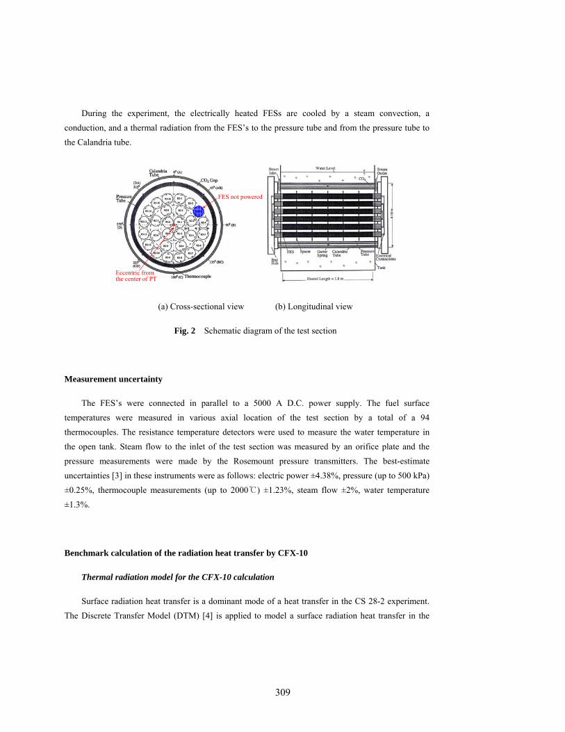
During the experiment, the electrically heated FESs are cooled by a steam convection, a conduction, and a thermal radiation from the FES’s to the pressure tube and from the pressure tube to the Calandria tube.
FES not powered
Eccentric from the center of PT
(a) Cross-sectional view (b) Longitudinal view
Fig. 2 Schematic diagram of the test section
Measurement uncertainty
The FES’s were connected in parallel to a 5000 A D.C. power supply. The fuel surface temperatures were measured in various axial location of the test section by a total of a 94 thermocouples. The resistance temperature detectors were used to measure the water temperature in the open tank. Steam flow to the inlet of the test section was measured by an orifice plate and the
pressure measurements were made by the Rosemount pressure transmitters. The best-estimate uncertainties [3] in these instruments were as follows: electric power ±4.38%, pressure (up to 500 kPa) ±0.25%, thermocouple measurements (up to 2000℃) ±1.23%, steam flow ±2%, water temperature ±1.3%.
Benchmark calculation of the radiation heat transfer by CFX-10
Thermal radiation model for the CFX-10 calculation
Surface radiation heat transfer is a dominant mode of a heat transfer in the CS 28-2 experiment. The Discrete Transfer Model (DTM) [4] is applied to model a surface radiation heat transfer in the
309

present study. The main assumption of the DTM is that the radiation leaving the surface element in a certain range of solid angles can be approximated by a single ray. A major advantage of the DTM is its fixed sampling in situations where the same mesh is to be used again and again, as in the case of a combined flow-radiation calculation for modeling a combustion chamber. In this case the ray paths
can be calculated once and stored thus providing a large improvement in the efficiency.
Boundary conditions for the benchmark problem
The validation calculation involves the problem of the radiation heat transfer between the FES bundle and the pressure tube. The geometry of the benchmark problem is the same as the test section of the CS28-2 experiment. The 28-element bundle consists of three rings and they are eccentrically located inside the pressure tube: 4 elements (R1-1 ~ R1-4) in the inner ring, 8 elements (R2-1 ~ R2-8)
in the middle ring, and 16 elements (R3-1 ~ R3-16) in the outer ring. Thermal power and temperature are given to each of the elements and the inside surface of the pressure tube, respectively. The geometry and boundary conditions are listed in Table 1.
Table 1 Geometry and boundary conditions of the radiation benchmark problem
Boundary conditions Component Thermal power
(kW/m3) Temperature,
(K)
Radius (mm)
Emissivity, εi
Thermal conductivity, k (W/m2·K)
Inner ring 1160.78 - 7.65 0.8 20.0
Middle ring 930.72 - 7.65 0.8 20.0 Elements
Outer ring 815.69 - 7.65 0.8 20.0
Pressure tube - 874.0 57.55 0.8 20.0
Benchmark test results
The temperature could not be uniform along the circumferential direction on the surface of each fuel element due to a circumferential conduction heat transfer and view factor variation. Therefore, the surfaces of each element are circumferentially divided into 6 segments. The segment angle is defined
so that the angle of the center-to-center line between each element and ring is 90 degree. Now we have to determine the heat flux distributions on each segment to obtain the temperature solutions by the Radiosity Matrix Method (RMM) [5]. The non-uniform heat fluxes for each segment are determined by the CATHEA [6, 7] code with a 6-segment model. Finally, 168 heat fluxes are provided for the
surfaces i (i = 1, 2, …, 28×6) of 28-element, and the temperature Ti (i = 169) for the surface of the
310
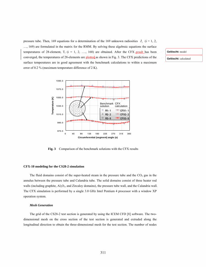
pressure tube. Then, 169 equations for a determination of the 169 unknown radiosities iJ (i = 1, 2,
…, 169) are formulated in the matrix for the RMM. By solving these algebraic equations the surface temperatures of 28-element, Ti (i = 1, 2, …., 168) are obtained. After the CFX result has been converged, the temperatures of 28-elements are plotted as shown in Fig. 3. The CFX predictions of the
surface temperatures are in good agreement with the benchmark calculations to within a maximum error of 0.2 % (maximum temperature difference of 2 K).
970.0
990.0
1010.0
1030.0
1050.0
1070.0
1090.0
0 45 90 135 180 225 270 315 360
Circumferential (segment) angle (o)
Tem
pera
ture
(K)
R1- 1 CFX1- 1R2- 2 CFX2- 2R3- 6 CFX3- 6
Benchmark solution
CFX calculation
Fig. 3 Comparison of the benchmark solutions with the CFX results
CFX-10 modeling for the CS28-2 simulation
The fluid domains consist of the super-heated steam in the pressure tube and the CO2 gas in the annulus between the pressure tube and Calandria tube. The solid domains consist of three heater rod
walls (including graphite, Al2O3, and Zircaloy domains), the pressure tube wall, and the Calandria wall. The CFX simulation is performed by a single 3.0 GHz Intel Pentium 4 processor with a window XP operation system.
Mesh Generation
The grid of the CS28-2 test section is generated by using the ICEM CFD [8] software. The two-dimensional mesh on the cross section of the test section is generated and extruded along the longitudinal direction to obtain the three-dimensional mesh for the test section. The number of nodes
Gelöscht: model
Gelöscht: calculated
311

with the longitudinal direction (for 1.8 m of an axial length) is 30 by the extrusion of two-dimensional mesh.
Figure 4 shows the results of the grid generation with a refined mesh density near the wall
boundaries. The number of the elements used is 764,901 and the number of the nodes is 1,014,888. If the number of the nodes is increased, it reaches the 2 GB memory limit that many users face when running large models on Windows.
Mesh layer near the solid wall
PT Heater rodSteam
Fig. 4 Mesh generation of the CS28-2 test section
Material properties
The materials used in the considered domain are graphite, Al2O3, Zircaloy, steam, and CO2.
Zircaloy is used for the FES sheath, pressure tube, and Calandria tube. These properties are the same as those used in the CATHENA code [6, 7].
The emissivities of the fuel sheath and inner and outer surfaces of the pressure tube are assumed
as constant and equal to 0.8. The emissivity of the inner surface of the calandria tube is set to 0.34.
Boundary conditions
The wall surfaces are assumed to be no-slip conditions. The modeling of a pool surrounding the Calandria tube is simplified by using the temperature boundary condition (40℃) on the outer surface of the Calandria tube. The steam injection flow is modeled by the mass flow rate boundary condition
312

on the inlet surface of the steam domain. A free stream flow with a uniform temperature and a uniform velocity are applied to the inlet plane and a zero relative static pressure is applied to the exit plane.
The FES power is modeled by an energy source within a solid sub-domain. The total thermal
power for a steady-state condition is 10 kW and the normalized ring radial powers are 1.111, 0.894 and 0.775 for the outer, middle, and inner FES rings, respectively.
Simulation results of the CS28-2 experiment
The present simulation of CS28-2 is performed only for steady-state conditions in this study.
The following parameters are chosen to show the comparison between the CFX-10 predictions and the experimental results: the temperature of the sheath surfaces of the inner, middle and outer
rings, the pressure tube temperature, and steam temperature.
Figures 5, 6 and 7 show the measured and predicted FES temperatures of the inner, middle and outer rings, respectively, at different axial locations. We can see that the FES temperatures are increasing inwards from the fuel bundle because the thermal energy generated in the 28-element is
radially transferred to the surrounding pressure tube. Since the heat generation rate in the FES is essentially uniform along the length of the test section, the steam flow along the test section leads to higher FES temperatures near the exit of the test section. The predictions of the FES temperatures are in good agreement with the measured data to within a ±2% of the error, which is defined as the ratio of
the temperature difference to the measured temperature. The uncertainties in the thermocouple readings are roughly ±1% plus there is some additional uncertainties arising from the radial temperature variations from the inner edge of the fuel ring to the outer edge. On this basis, the FES thermocouple readings have a maximum uncertainty of ±20 ~ ±30℃ during the steady-state condition.
The maximum difference between the predictions and the measured data is less than 20 ℃, which is less than the uncertainty of the temperature measurements.
Figure 8 shows the comparison between the measured data and the CFX-10 predictions for the
pressure tube temperatures at different axial locations. The CFX-10 predicted the measured data excellently at the locations of 0.525 m and 0.825 m, but it under-estimated them at the locations of 1.125 m and 1.725 m. The difference between the code prediction and the measured data is about 50 ℃ at location of 1.725 m. The difference exceeds the uncertainty of the temperature measurements
which remains unexplained.
313

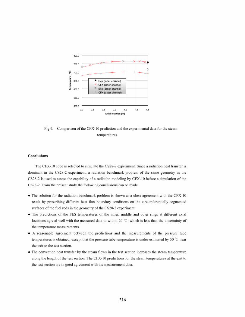
The measured and predicted steam temperatures at the exit to the test section are shown in Fig. 9. The agreement is reasonably good between the measurements and the code predictions for the steam temperatures, especially inside the inner sub-channel (between the inner ring and the middle ring).
500.0
550.0
600.0
650.0
700.0
750.0
800.0
0.0 0.3 0.6 0.9 1.2 1.5 1.8
Axial location (m)
Tem
pera
ture
(o C
)
Exp. CFX
Fig 5. Comparison of the CFX-10 prediction and the experimental data for the FES temperatures in the inner ring
500.0
550.0
600.0
650.0
700.0
750.0
800.0
0.0 0.3 0.6 0.9 1.2 1.5 1.8
Axial location (m)
Tem
pera
ture
(o C
)
Exp. CFX
Fig 6. Comparison of the CFX-10 prediction and the experimental data for the FES temperatures in the middle ring
314

500.0
550.0
600.0
650.0
700.0
750.0
800.0
0.0 0.3 0.6 0.9 1.2 1.5 1.8
Axial location (m)
Tem
pera
ture
(o C
)
Exp. CFX
Fig 7. Comparison of the CFX-10 prediction and the experimental data for the FES
temperatures in the outer ring
500.0
550.0
600.0
650.0
700.0
750.0
800.0
0.0 0.3 0.6 0.9 1.2 1.5 1.8
Axial location (m)
Tem
pera
ture
(o C
)
Exp. CFX
Fig 8. Comparison of the CFX-10 prediction and the experimental data for the pressure tube temperatures
315
500.0
550.0
600.0
650.0
700.0
750.0
800.0
0.0 0.3 0.6 0.9 1.2 1.5 1.8
Axial location (m)
Tem
pera
ture
(o C
)
Exp.(inner channel)CFX (inner channel)Exp.(outer channel)CFX (outer channel)
Fig 9. Comparison of the CFX-10 prediction and the experimental data for the steam temperatures
Conclusions
The CFX-10 code is selected to simulate the CS28-2 experiment. Since a radiation heat transfer is
dominant in the CS28-2 experiment, a radiation benchmark problem of the same geometry as the CS28-2 is used to assess the capability of a radiation modeling by CFX-10 before a simulation of the CS28-2. From the present study the following conclusions can be made.
● The solution for the radiation benchmark problem is shown as a close agreement with the CFX-10 result by prescribing different heat flux boundary conditions on the circumferentially segmented surfaces of the fuel rods in the geometry of the CS28-2 experiment.
● The predictions of the FES temperatures of the inner, middle and outer rings at different axial
locations agreed well with the measured data to within 20 ℃, which is less than the uncertainty of the temperature measurements.
● A reasonable agreement between the predictions and the measurements of the pressure tube temperatures is obtained, except that the pressure tube temperature is under-estimated by 50 ℃ near
the exit to the test section. ● The convection heat transfer by the steam flows in the test section increases the steam temperature
along the length of the test section. The CFX-10 predictions for the steam temperatures at the exit to the test section are in good agreement with the measurement data.
316

The present simulation of CS28-2 is performed for steady-state conditions. Further works are recommended to complete the simulation for the transient phase of the CS28-2 experiment.
Acknowledgements
This work has been carried out under the Nuclear Research and Development program of Korea Ministry of Science and Technology.
References
[1] D.B. Sanderson, K.A. Haugen, R.G. Moyer, H.E. Rosinger, “Out-of-Pile Fuel Channel Experiments for Severe Accident Conditions,” Proc. ANS International Topical Meeting on Safety of Thermal Reactors, Portland, Oregon, July (1991).
[2] M.H. Bayoumi, W.C. Muir, “Post-Test Simulation and Analysis of the Second Full Scale CHAN
28-Element Experiment (Validation of CHAN-II (MOD6) against Experiments),” Proc. 16th Ann. Conf. of Canadian Nuclear Society, Saskatoon, Canada, June 4-7, (1995).
[3] P.J. Mills, D.B. Sanderson, K.A. Haugen, et al., “Twenty-Eight Element Fuel Channel Thermal-
Chemical Experiments,” Proc. 17th Ann. Conf. of Canadian Nuclear Society, Fredericton, Canada, June 9-12, (1996).
[4] ANSYS CFX-Solver, Release 10.0: Theory, ANSYS, Inc., Canonsburg, (2005).
[5] M.N. Özişik, Heat Transfer: A Basic Approach, McGraw-Hill, New York, 643 (1985).
[6] B.N. Hanna, “CATHENA: A Thermalhydraulic Code for CANDU Analysis,” Nuclear Engineering
and Design, 180[2], 113(1998).
[7] B.N. Hanna, CATHENA MOD-3.5 / Rev 0, Theoretical Manual, RC-982-2, Atomic Energy of Canada Limited, (1995).
[8] ANSYS ICEM CFD, Release 10.0: Tutorial Manual, ANSYS, Inc., Canonsburg, (2005).
317

318