ch 601 xl / ch650 upgrade package: section 6-zu-1, wing ... · this photo assembly guide was...
TRANSCRIPT

Zodiac 601XL & 650
Zenith Aircraft Company www.zenithair.com
Wing Spar & Rear Channel Section 6-ZU-1, Page 1 of 26
Revision 1.1 (2/16/10) © 2009 Zenith Aircraft Co.
Section 6-ZU-1 Zodiac CH 601 XL Upgrade Package
Wing Spar & Rear Channel
This Photo Assembly Guide was prepared by Zenith Aircraft Co. to guide builders through the process of installing the Upgrade Package kit to an existing (completed) Zodiac CH 601 XL aircraft. For details and background information on the Upgrade Package kit, See http://www.zenithair.com/news/ntsb-astm-4-09a.html This photo assembly manual is a supplement to the issued Drawings (6-ZU-1 to 6-ZU-4). If there is any discrepancy between this manual and the drawings, the drawings supersede this manual. For more information on building standards and allowable tolerances see “Construction Standards for Zenair Light Aircraft” available from Zenith Aircraft Co.
Zodiac 601XL & 650
Zenith Aircraft Company www.zenithair.com
Wing Spar & Rear Channel Section 6-ZU-1, Page 2 of 26
Revision 1.1 (2/16/10) © 2009 Zenith Aircraft Co.
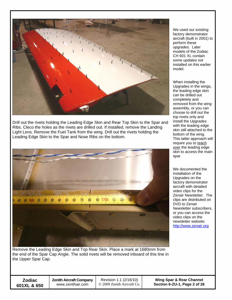
Drill out the rivets holding the Leading Edge Skin and Rear Top Skin to the Spar and Ribs. Cleco the holes as the rivets are drilled out. If installed, remove the Landing Light Lens. Remove the Fuel Tank from the wing. Drill out the rivets holding the Leading Edge Skin to the Spar and Nose Ribs on the bottom.
Remove the Leading Edge Skin and Top Rear Skin. Place a mark at 1680mm from the end of the Spar Cap Angle. The solid rivets will be removed inboard of this line in the Upper Spar Cap.
We used our existing factory demonstrator aircraft (built in 2001) to perform these upgrades. Later models of the Zodiac CH 601 XL contain some updates not installed on this earlier model. When installing the Upgrades in the wings, the leading edge skin can be drilled out completely and removed from the wing assembly, or you can choose to drill out the top rivets only and install the Upgrades with the leading edge skin still attached to the bottom of the wing. This latter approach will require you to reach over the leading edge skin to access the main spar. We documented the installation of the Upgrades on the factory demonstrator aircraft with detailed video clips for the Zenair Newsletter. The clips are distributed on DVD to Zenair Newsletter subscribers, or you can access the video clips on the newsletter website: http://www.zenair.org

Zodiac 601XL & 650
Zenith Aircraft Company www.zenithair.com
Wing Spar & Rear Channel Section 6-ZU-1, Page 3 of 26
Revision 1.1 (2/16/10) © 2009 Zenith Aircraft Co.
Use a Center Punch on the dimple on the head of the solid rivets holding the Upper Spar caps to the Spar Web. Determine if the solid rivets are 5/32” or 3/16” diameter. The set side of a 5/32” rivet should be approximately 6mm in diameter. A 3/16” is approximately 7.1mm. See “Construction Standards for Zenair Light Airplanes” for specific tolerances.
Drill into the head of the solid rivet, use a #40 drill for 5/32” rivets and a #30 for 3/16” rivets. Only drill to the approximate depth of the rivet head. Then use a chisel and hammer to knock off the head of the rivet.

Zodiac 601XL & 650
Zenith Aircraft Company www.zenithair.com
Wing Spar & Rear Channel Section 6-ZU-1, Page 4 of 26
Revision 1.1 (2/16/10) © 2009 Zenith Aircraft Co.
With the head of the rivet removed, use a punch to start tapping the rivet out of the hole, use a #30 punch for a 5/32” rivet and a #20 punch for a 3/16” rivet. The rivet can be driven out entirely with a hammer and punch but is difficult.
Use a peunmatic rivet gun with the punch to tap out the rivet the remaining distance. Make sure the punch is on the rivet and not the Spar Cap. The punch can severly damage the cap if it is hit instead of the rivet. Cleco several holes as the rivets are removed. Clamps may be required next to the rivet being removed to prevent the parts from seperating instead of driving the rivets out.
Zodiac 601XL & 650
Zenith Aircraft Company www.zenithair.com
Wing Spar & Rear Channel Section 6-ZU-1, Page 5 of 26
Revision 1.1 (2/16/10) © 2009 Zenith Aircraft Co.
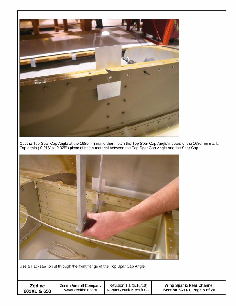
Cut the Top Spar Cap Angle at the 1680mm mark, then notch the Top Spar Cap Angle inboard of the 1680mm mark. Tap a thin ( 0.016” to 0.025”) piece of scrap material between the Top Spar Cap Angle and the Spar Cap.
Use a Hacksaw to cut through the front flange of the Top Spar Cap Angle.
Zodiac 601XL & 650
Zenith Aircraft Company www.zenithair.com
Wing Spar & Rear Channel Section 6-ZU-1, Page 6 of 26
Revision 1.1 (2/16/10) © 2009 Zenith Aircraft Co.
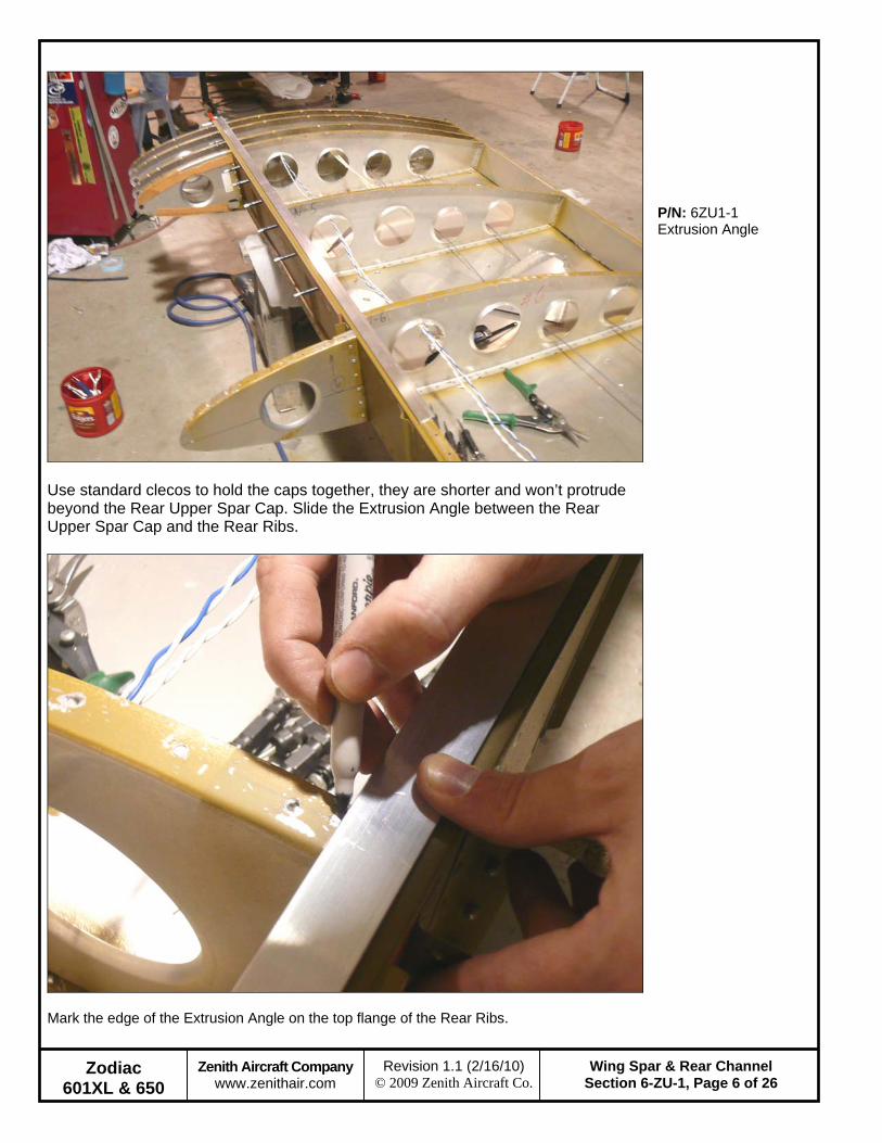
Use standard clecos to hold the caps together, they are shorter and won’t protrude beyond the Rear Upper Spar Cap. Slide the Extrusion Angle between the Rear Upper Spar Cap and the Rear Ribs.
P/N: 6ZU1-1 Extrusion Angle
Mark the edge of the Extrusion Angle on the top flange of the Rear Ribs.

Zodiac 601XL & 650
Zenith Aircraft Company www.zenithair.com
Wing Spar & Rear Channel Section 6-ZU-1, Page 7 of 26
Revision 1.1 (2/16/10) © 2009 Zenith Aircraft Co.
Mark a line on the web of the Rear Ribs from the mark on the top flange to the corner relief hole at the front flange.
Trim the Rear Ribs along the line. Use a file to clean up any rough edges left after trimming.
Zodiac 601XL & 650
Zenith Aircraft Company www.zenithair.com
Wing Spar & Rear Channel Section 6-ZU-1, Page 8 of 26
Revision 1.1 (2/16/10) © 2009 Zenith Aircraft Co.
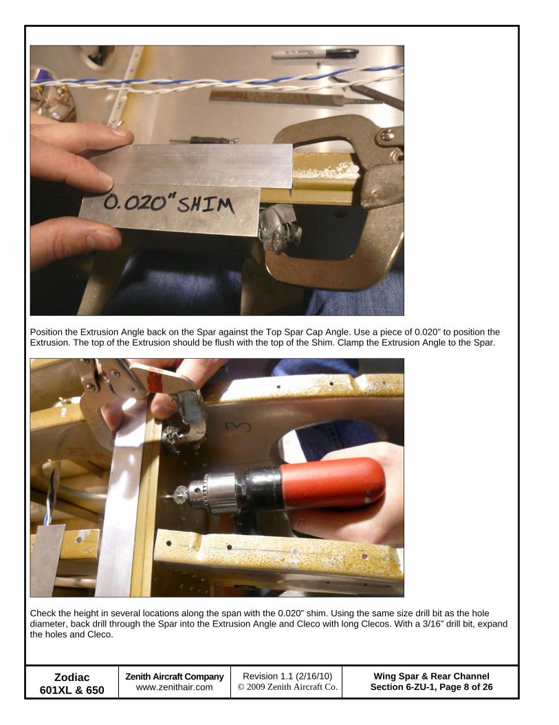
Position the Extrusion Angle back on the Spar against the Top Spar Cap Angle. Use a piece of 0.020” to position the Extrusion. The top of the Extrusion should be flush with the top of the Shim. Clamp the Extrusion Angle to the Spar.
Check the height in several locations along the span with the 0.020” shim. Using the same size drill bit as the hole diameter, back drill through the Spar into the Extrusion Angle and Cleco with long Clecos. With a 3/16” drill bit, expand the holes and Cleco.

Zodiac 601XL & 650
Zenith Aircraft Company www.zenithair.com
Wing Spar & Rear Channel Section 6-ZU-1, Page 9 of 26
Revision 1.1 (2/16/10) © 2009 Zenith Aircraft Co.
Drill out the rivets attaching Nose Rivet #1 to the Nose Rib Angle. Then drill out the rivets in the Nose Rib Angle to the Spar Web and remove the Nose Rib Angle.
Solid rivet the Extrusion Angle to the Spar. It is much easier to have someone help set the solid rivets. It is a good idea to practice solid riveting a few times on scrap material to get a feel for solid riveting. Reference: See ‘Construction Standards for Zenair Light Airplanes’ for the applicable tolerances for solid riveting.
Zodiac 601XL & 650
Zenith Aircraft Company www.zenithair.com
Wing Spar & Rear Channel Section 6-ZU-1, Page 10 of 26
Revision 1.1 (2/16/10) © 2009 Zenith Aircraft Co.
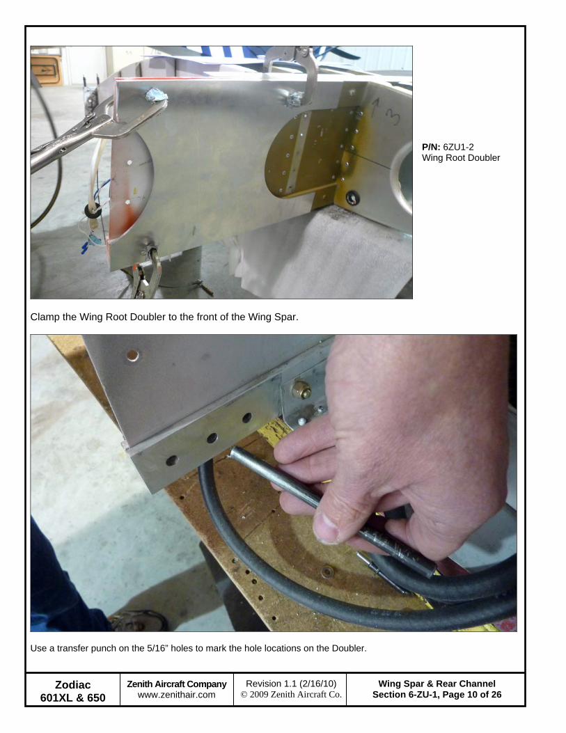
Clamp the Wing Root Doubler to the front of the Wing Spar.
P/N: 6ZU1-2 Wing Root Doubler
Use a transfer punch on the 5/16” holes to mark the hole locations on the Doubler.
Zodiac 601XL & 650
Zenith Aircraft Company www.zenithair.com
Wing Spar & Rear Channel Section 6-ZU-1, Page 11 of 26
Revision 1.1 (2/16/10) © 2009 Zenith Aircraft Co.
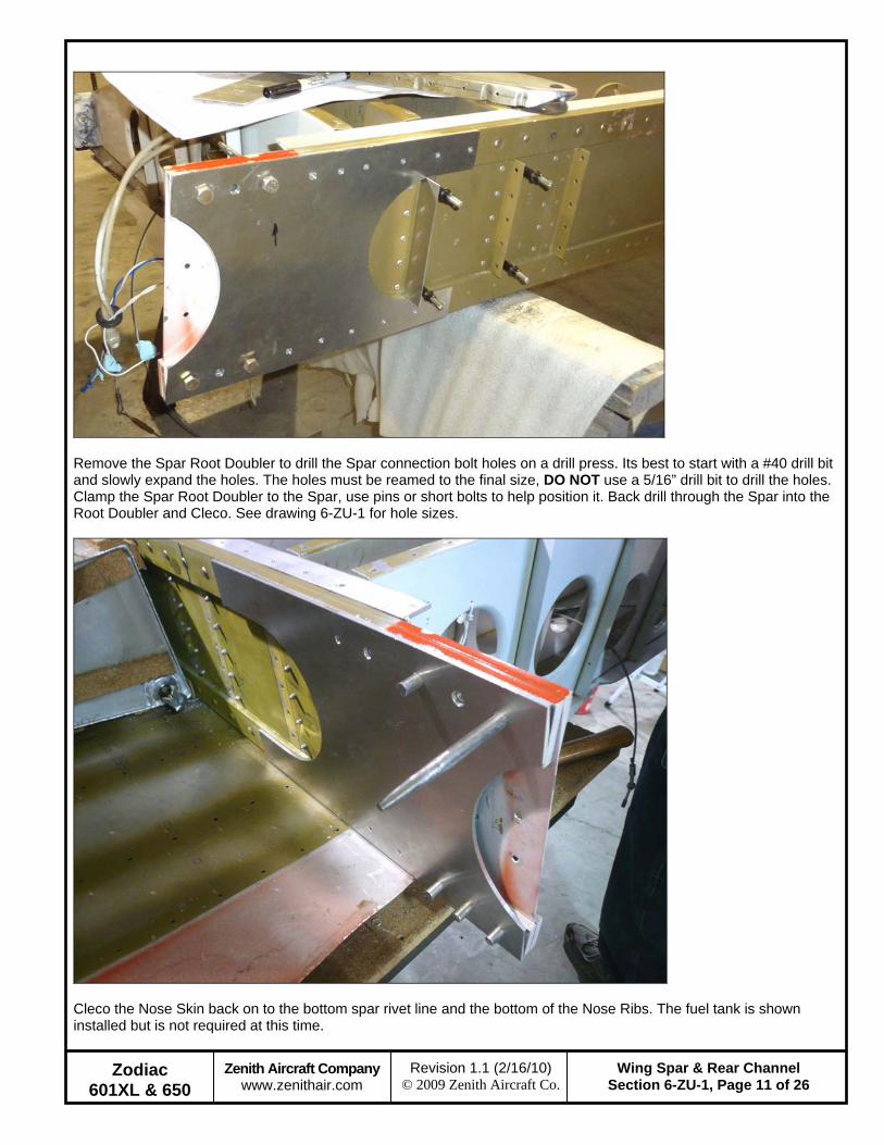
Remove the Spar Root Doubler to drill the Spar connection bolt holes on a drill press. Its best to start with a #40 drill bit and slowly expand the holes. The holes must be reamed to the final size, DO NOT use a 5/16” drill bit to drill the holes. Clamp the Spar Root Doubler to the Spar, use pins or short bolts to help position it. Back drill through the Spar into the Root Doubler and Cleco. See drawing 6-ZU-1 for hole sizes.
Cleco the Nose Skin back on to the bottom spar rivet line and the bottom of the Nose Ribs. The fuel tank is shown installed but is not required at this time.
Zodiac 601XL & 650
Zenith Aircraft Company www.zenithair.com
Wing Spar & Rear Channel Section 6-ZU-1, Page 12 of 26
Revision 1.1 (2/16/10) © 2009 Zenith Aircraft Co.
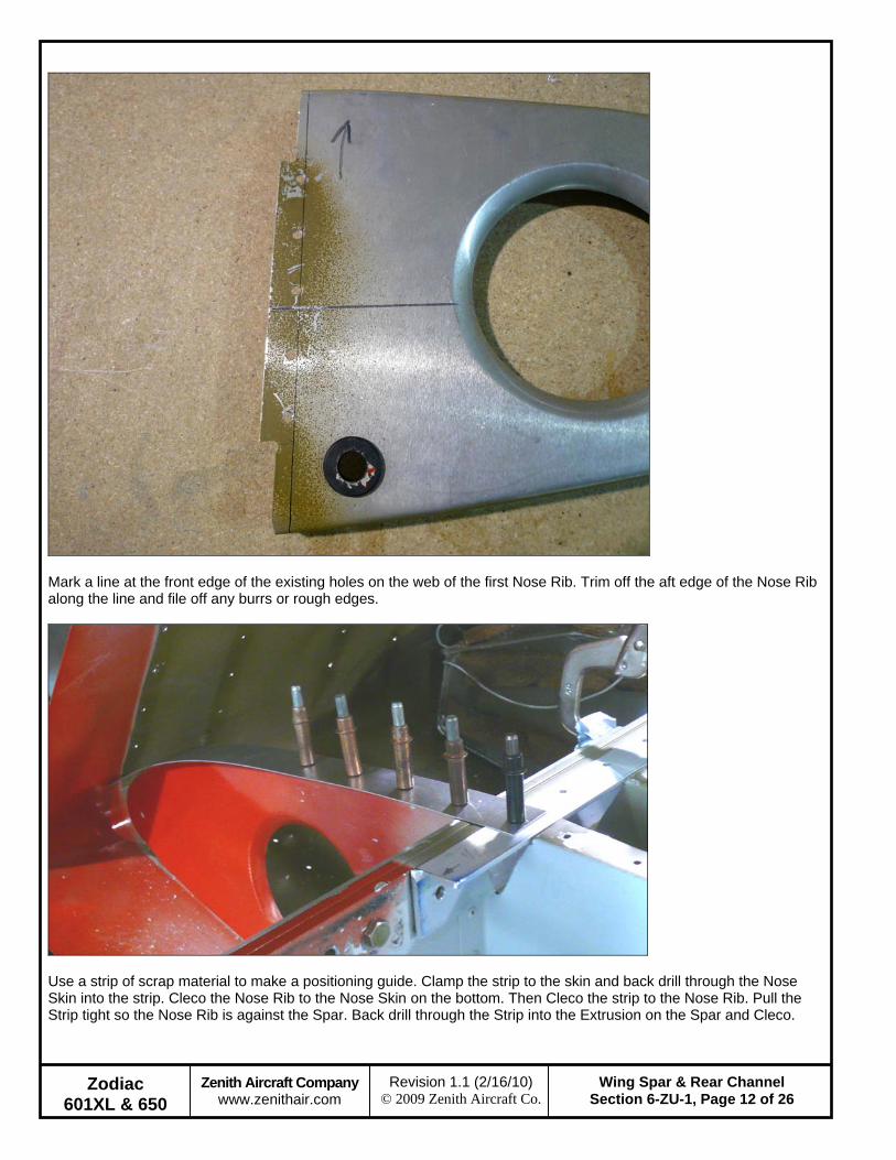
Mark a line at the front edge of the existing holes on the web of the first Nose Rib. Trim off the aft edge of the Nose Rib along the line and file off any burrs or rough edges.
Use a strip of scrap material to make a positioning guide. Clamp the strip to the skin and back drill through the Nose Skin into the strip. Cleco the Nose Rib to the Nose Skin on the bottom. Then Cleco the strip to the Nose Rib. Pull the Strip tight so the Nose Rib is against the Spar. Back drill through the Strip into the Extrusion on the Spar and Cleco.
Zodiac 601XL & 650
Zenith Aircraft Company www.zenithair.com
Wing Spar & Rear Channel Section 6-ZU-1, Page 13 of 26
Revision 1.1 (2/16/10) © 2009 Zenith Aircraft Co.
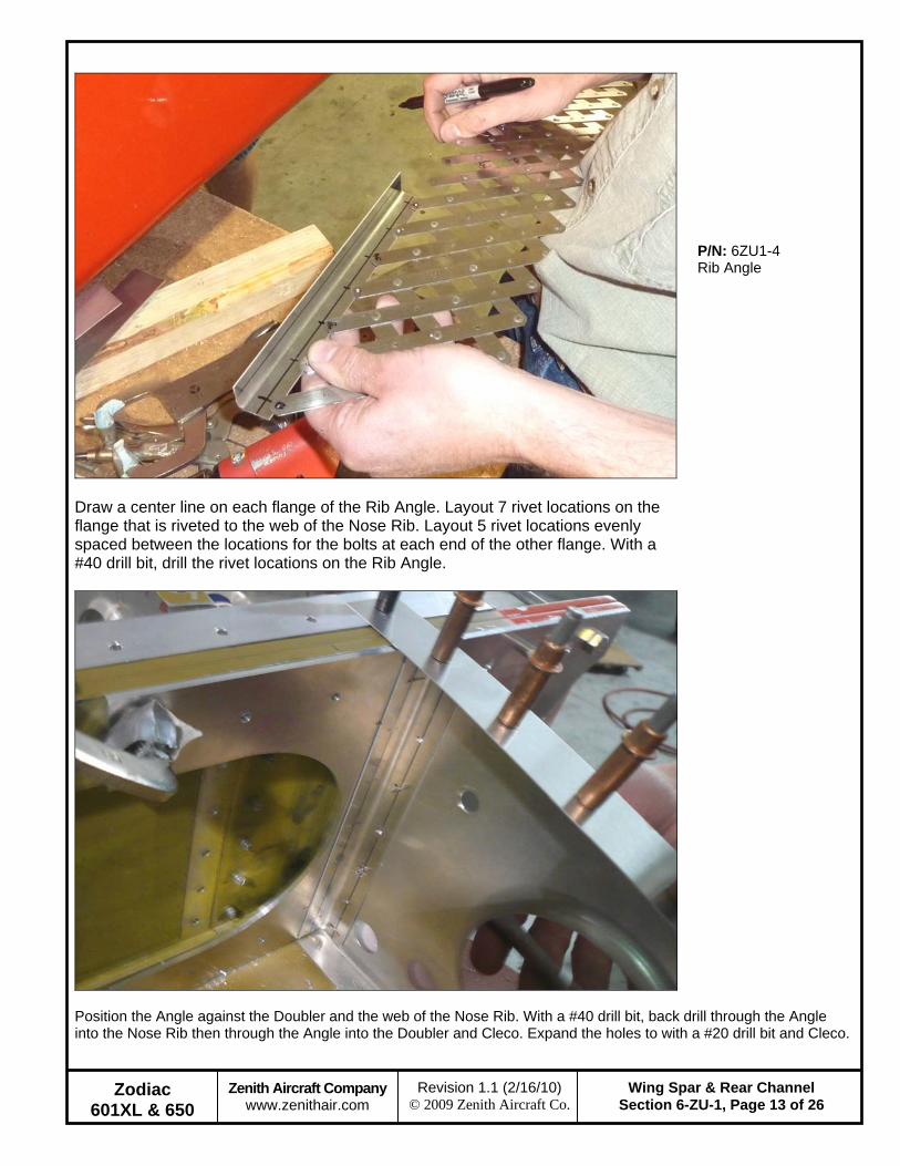
Draw a center line on each flange of the Rib Angle. Layout 7 rivet locations on the flange that is riveted to the web of the Nose Rib. Layout 5 rivet locations evenly spaced between the locations for the bolts at each end of the other flange. With a #40 drill bit, drill the rivet locations on the Rib Angle.
P/N: 6ZU1-4 Rib Angle
Position the Angle against the Doubler and the web of the Nose Rib. With a #40 drill bit, back drill through the Angle into the Nose Rib then through the Angle into the Doubler and Cleco. Expand the holes to with a #20 drill bit and Cleco.
Zodiac 601XL & 650
Zenith Aircraft Company www.zenithair.com
Wing Spar & Rear Channel Section 6-ZU-1, Page 14 of 26
Revision 1.1 (2/16/10) © 2009 Zenith Aircraft Co.
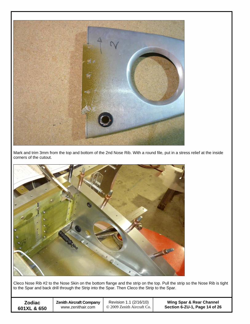
Mark and trim 3mm from the top and bottom of the 2nd Nose Rib. With a round file, put in a stress relief at the inside corners of the cutout.
Cleco Nose Rib #2 to the Nose Skin on the bottom flange and the strip on the top. Pull the strip so the Nose Rib is tight to the Spar and back drill through the Strip into the Spar. Then Cleco the Strip to the Spar.
Zodiac 601XL & 650
Zenith Aircraft Company www.zenithair.com
Wing Spar & Rear Channel Section 6-ZU-1, Page 15 of 26
Revision 1.1 (2/16/10) © 2009 Zenith Aircraft Co.
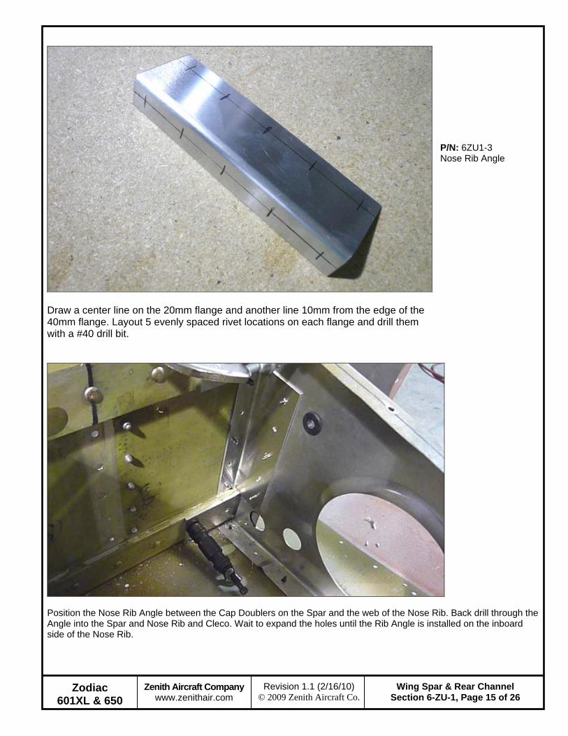
Draw a center line on the 20mm flange and another line 10mm from the edge of the 40mm flange. Layout 5 evenly spaced rivet locations on each flange and drill them with a #40 drill bit.
P/N: 6ZU1-3 Nose Rib Angle
Position the Nose Rib Angle between the Cap Doublers on the Spar and the web of the Nose Rib. Back drill through the Angle into the Spar and Nose Rib and Cleco. Wait to expand the holes until the Rib Angle is installed on the inboard side of the Nose Rib.
Zodiac 601XL & 650
Zenith Aircraft Company www.zenithair.com
Wing Spar & Rear Channel Section 6-ZU-1, Page 16 of 26
Revision 1.1 (2/16/10) © 2009 Zenith Aircraft Co.
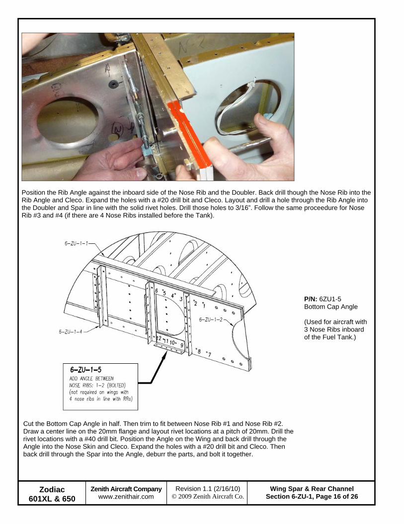
Position the Rib Angle against the inboard side of the Nose Rib and the Doubler. Back drill though the Nose Rib into the Rib Angle and Cleco. Expand the holes with a #20 drill bit and Cleco. Layout and drill a hole through the Rib Angle into the Doubler and Spar in line with the solid rivet holes. Drill those holes to 3/16”. Follow the same proceedure for Nose Rib #3 and #4 (if there are 4 Nose Ribs installed before the Tank).
Cut the Bottom Cap Angle in half. Then trim to fit between Nose Rib #1 and Nose Rib #2. Draw a center line on the 20mm flange and layout rivet locations at a pitch of 20mm. Drill the rivet locations with a #40 drill bit. Position the Angle on the Wing and back drill through the Angle into the Nose Skin and Cleco. Expand the holes with a #20 drill bit and Cleco. Then back drill through the Spar into the Angle, deburr the parts, and bolt it together.
P/N: 6ZU1-5 Bottom Cap Angle (Used for aircraft with 3 Nose Ribs inboard of the Fuel Tank.)
Zodiac 601XL & 650
Zenith Aircraft Company www.zenithair.com
Wing Spar & Rear Channel Section 6-ZU-1, Page 17 of 26
Revision 1.1 (2/16/10) © 2009 Zenith Aircraft Co.
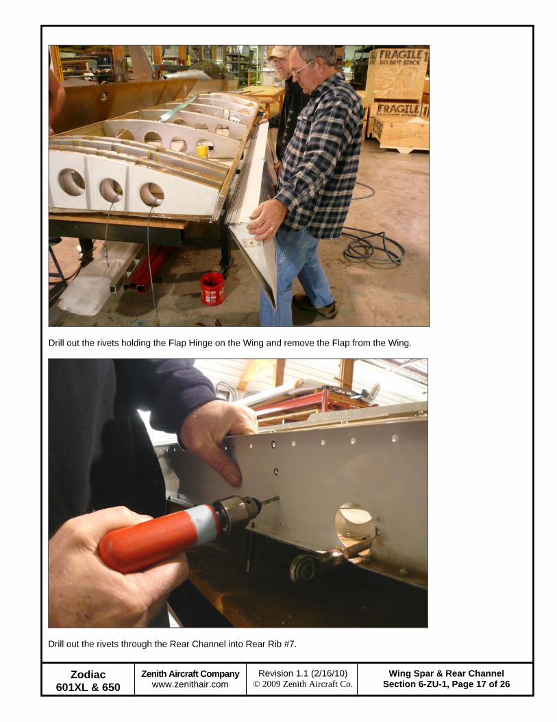
Drill out the rivets holding the Flap Hinge on the Wing and remove the Flap from the Wing.
Drill out the rivets through the Rear Channel into Rear Rib #7.

Zodiac 601XL & 650
Zenith Aircraft Company www.zenithair.com
Wing Spar & Rear Channel Section 6-ZU-1, Page 18 of 26
Revision 1.1 (2/16/10) © 2009 Zenith Aircraft Co.
Remove the Threaded Steel Rod from the Aileron Bellcrank.
Mark a line 10mm from the inboard end of the Doubler. Orientation: The bent flange is positioned on the bottom side of the Rear Channel.
P/N: 6ZU1-8 Aileron Rod Hole Doubler

Zodiac 601XL & 650
Zenith Aircraft Company www.zenithair.com
Wing Spar & Rear Channel Section 6-ZU-1, Page 19 of 26
Revision 1.1 (2/16/10) © 2009 Zenith Aircraft Co.
Position the Doubler on the Rear Channel with the line visible through the holes in the Rear Channel for Rear Rib #7. Clamp the Doubler to the Rear Channel. Back drill the holes for Rear Rib #7 through the Rear Channel into the Doubler and Cleco.
Trace the hole for the Rod on the Doubler. Remove the Doubler to cut the hole for the Rod.

Zodiac 601XL & 650
Zenith Aircraft Company www.zenithair.com
Wing Spar & Rear Channel Section 6-ZU-1, Page 20 of 26
Revision 1.1 (2/16/10) © 2009 Zenith Aircraft Co.
Drill a hole in the center of the cutout. Use snips to expand the cutout to the line. Layout a line 10mm from the outboard edge and up 10mm from the bottom of the Doubler. Layout four holes evenly spaced on the outboard edge and two holes evenly spaced along the bottom. Wait to drill the holes along the top of the Doubler.
Cleco the Doubler back in place. Drill the rivet locations through the Doubler into the Rear Channel and Cleco. The holes in the top of the Doubler will be drilled with the Top Rear Spar Angle in the following steps.
Zodiac 601XL & 650
Zenith Aircraft Company www.zenithair.com
Wing Spar & Rear Channel Section 6-ZU-1, Page 21 of 26
Revision 1.1 (2/16/10) © 2009 Zenith Aircraft Co.
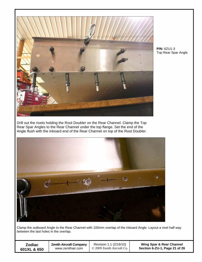
Drill out the rivets holding the Root Doubler on the Rear Channel. Clamp the Top Rear Spar Angles to the Rear Channel under the top flange. Set the end of the Angle flush with the inboard end of the Rear Channel on top of the Root Doubler.
P/N: 6ZU1-3 Top Rear Spar Angle
Clamp the outboard Angle to the Rear Channel with 100mm overlap of the inboard Angle. Layout a rivet half way between the last holes in the overlap.
Zodiac 601XL & 650
Zenith Aircraft Company www.zenithair.com
Wing Spar & Rear Channel Section 6-ZU-1, Page 22 of 26
Revision 1.1 (2/16/10) © 2009 Zenith Aircraft Co.
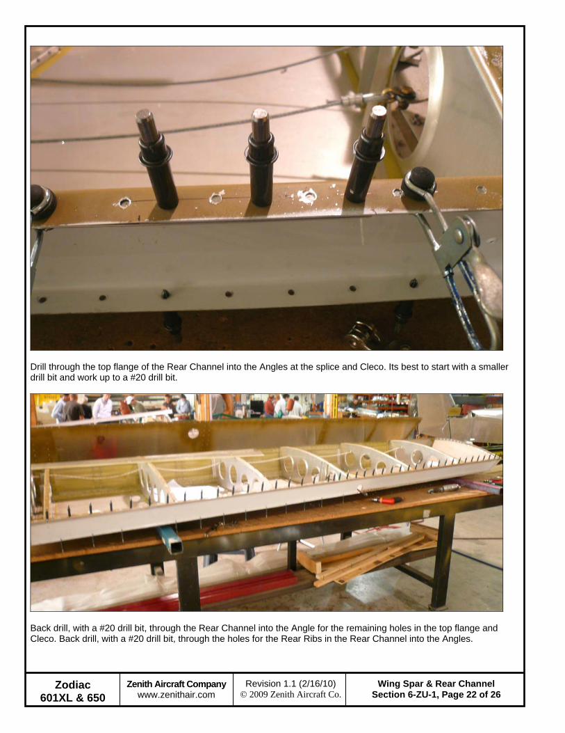
Drill through the top flange of the Rear Channel into the Angles at the splice and Cleco. Its best to start with a smaller drill bit and work up to a #20 drill bit.
Back drill, with a #20 drill bit, through the Rear Channel into the Angle for the remaining holes in the top flange and Cleco. Back drill, with a #20 drill bit, through the holes for the Rear Ribs in the Rear Channel into the Angles.
Zodiac 601XL & 650
Zenith Aircraft Company www.zenithair.com
Wing Spar & Rear Channel Section 6-ZU-1, Page 23 of 26
Revision 1.1 (2/16/10) © 2009 Zenith Aircraft Co.
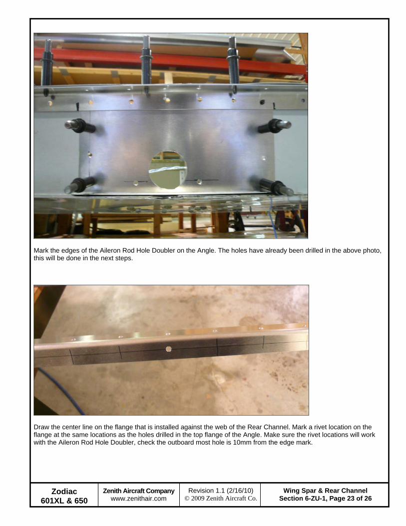
Mark the edges of the Aileron Rod Hole Doubler on the Angle. The holes have already been drilled in the above photo, this will be done in the next steps.
Draw the center line on the flange that is installed against the web of the Rear Channel. Mark a rivet location on the flange at the same locations as the holes drilled in the top flange of the Angle. Make sure the rivet locations will work with the Aileron Rod Hole Doubler, check the outboard most hole is 10mm from the edge mark.

Zodiac 601XL & 650
Zenith Aircraft Company www.zenithair.com
Wing Spar & Rear Channel Section 6-ZU-1, Page 24 of 26
Revision 1.1 (2/16/10) © 2009 Zenith Aircraft Co.
With a #40 drill bit, drill the rivet locations on the Angle. Cleco the Angles back to the Rear Channel. Back drill through the Angle into the Rear Channel and Cleco. Expand the holes with a #20 drill bit.
Drill out the rivets in the Hinge Doubler and Root Doubler. Remove the Hinge Doubler from the Wing, this part is replaced by the Rear Channel Doubler.
Zodiac 601XL & 650
Zenith Aircraft Company www.zenithair.com
Wing Spar & Rear Channel Section 6-ZU-1, Page 25 of 26
Revision 1.1 (2/16/10) © 2009 Zenith Aircraft Co.
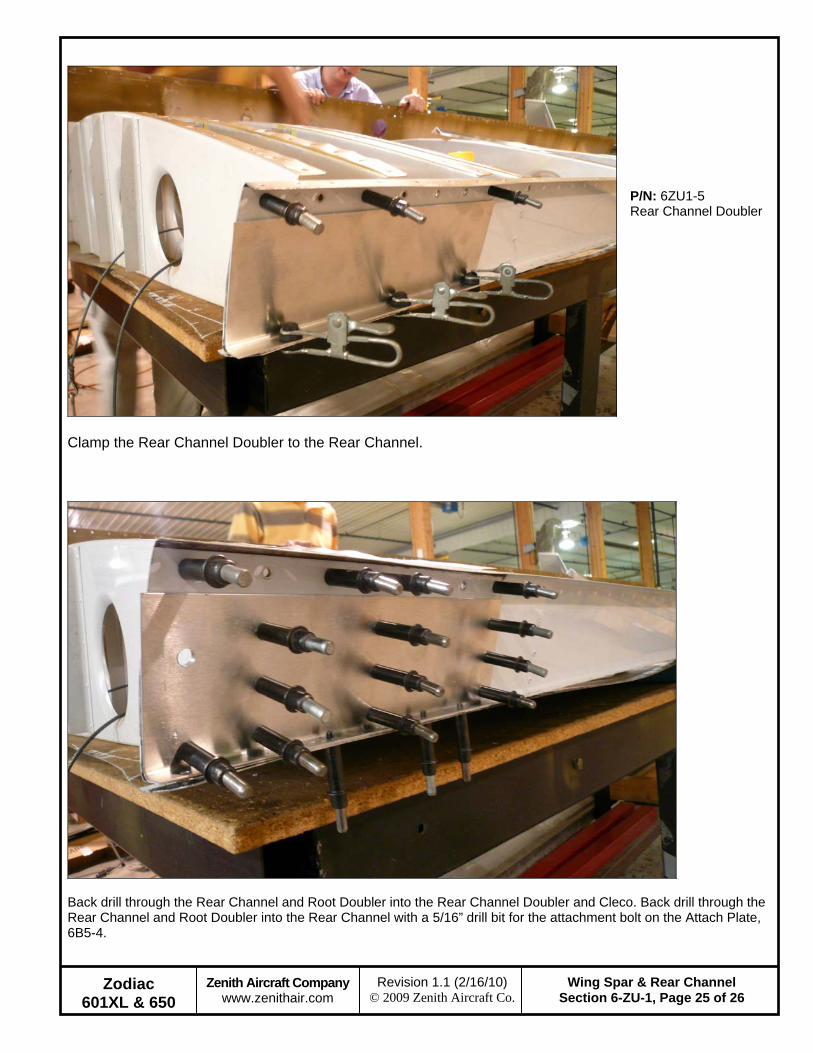
Clamp the Rear Channel Doubler to the Rear Channel.
P/N: 6ZU1-5 Rear Channel Doubler
Back drill through the Rear Channel and Root Doubler into the Rear Channel Doubler and Cleco. Back drill through the Rear Channel and Root Doubler into the Rear Channel with a 5/16” drill bit for the attachment bolt on the Attach Plate, 6B5-4.

Zodiac 601XL & 650
Zenith Aircraft Company www.zenithair.com
Wing Spar & Rear Channel Section 6-ZU-1, Page 26 of 26
Revision 1.1 (2/16/10) © 2009 Zenith Aircraft Co.
Draw a line between the second rivet from the top for the Rear Ribs on the Rear Channel Doubler. Mark a rivet location half way between Rear Rib #1 and Rear Rib #2. Then evenly space two rivet locations between Rear Rib #2 and Rear Rib #3. With a #40 drill bit, drill through the Rear Channel Doubler into the Root Doubler and Rear Channel. The expand the holes with a #20 drill bit.
Rivet the Rear Channel Doubler, Top Rear Spar Angle and Aileron Rod Hole Doubler to the Rear Channel on the WEB only. In the photo above the Wing has been closed, this is done later.