ch- 9
DESCRIPTION
CHAPTER 9TRANSCRIPT

Chapter 9
MF F312


Die cutting operations

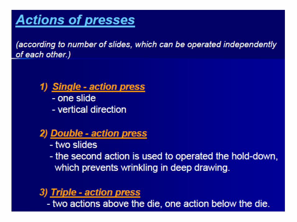
Power press types
• The frame of a press fabricated by Costing or welding • Mechanical or hydraulic• Non gear single reduction gear and double reduction gear


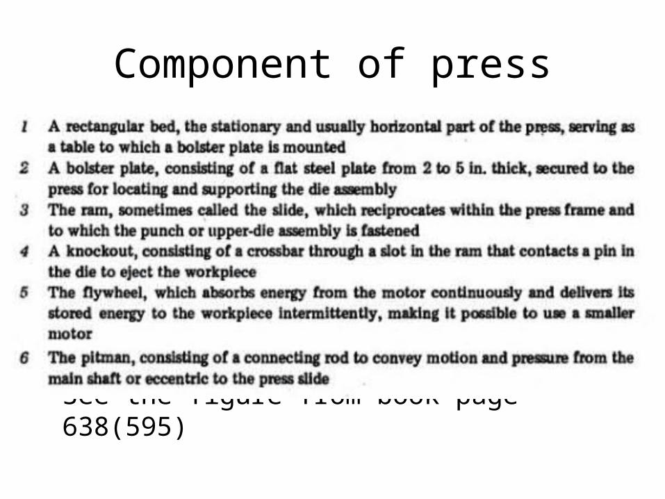
Component of press
• See the figure from book page 638(595)

General press information
• Press tonnage: tonnage of force that press ram is able to exert
• Stroke: reciprocating motion of press slide, number of in b/w terminal point
• Shut height: height of a press b/w distance of top of the bed to bottom of slide
• Die space: area available for mounting dies in the press

Material handling equipment• Metal Unwinding Equipment• Metal coil unwinding equipment is used to process continuous
lengths of metal sheet, wire or foil in converting, coating, sheeting, and manufacturing applications.
• Metal coil unwinders are used to produce solenoid bobbins, solenoid potted coils, transformer coils, choke coils, inductor coals, and generator coils.
• Metal coil unwinders are also used with a variety of products, and may be incorporated into a coil coating line that includes a web unwind or feed section.
• Metal coil unwinding equipment features single-spindle and multiple-spindle designs, and is available in bench top and stand-alone models. There are many types of metal coil winding and metal coil unwinding equipment.

• strip straightening devices: used for removing wrinkles and curvature after uncoiling
• It is an intermediate step b/w uncoiling and feeding
• strip feeding equipment: factors depends with, thickness and surface condition of the material

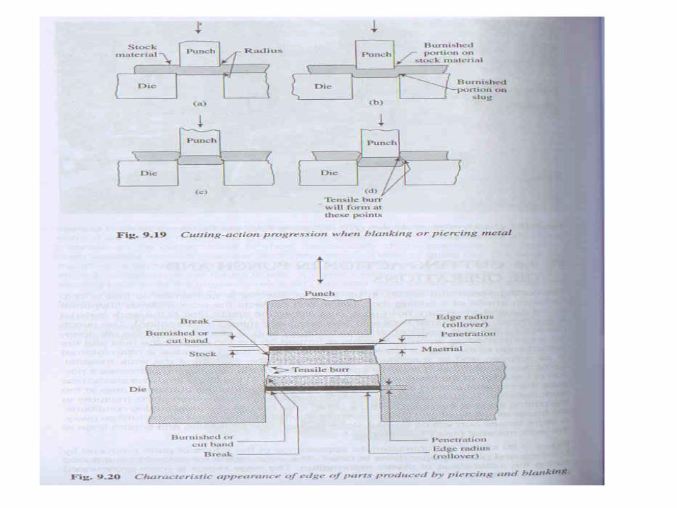
Cutting action in punch and Die Operations
• See the page of 651

Die clearance• Die Clearance, as we define it, is the total difference between
the Punch and Die dimensions. • Many studies have been made throughout the Metalworking
Industry regarding the proper amount of clearance to be allowed between Punch and Die.
• Results vary considerably due to the many variables involved such as type and hardness of material, type and speed of press, design of Punching Tools, finish on Punches and Dies, etc.
• Through continued research and experience, we have arrived at the following recommendations for the various styles of tooling.
• See the page 654-655
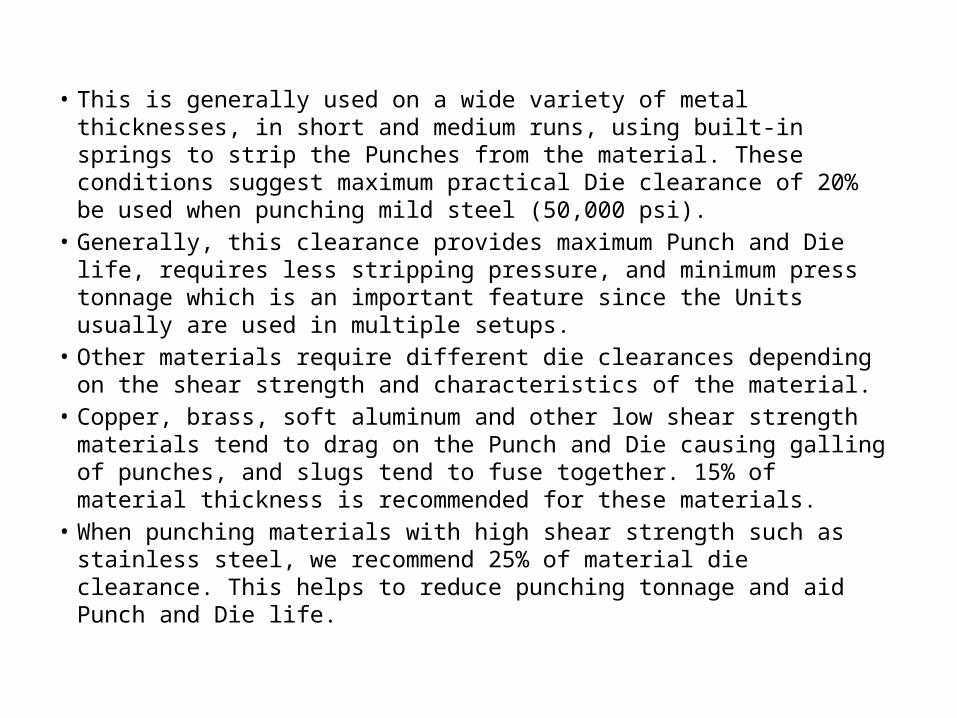
• This is generally used on a wide variety of metal thicknesses, in short and medium runs, using built-in springs to strip the Punches from the material. These conditions suggest maximum practical Die clearance of 20% be used when punching mild steel (50,000 psi).
• Generally, this clearance provides maximum Punch and Die life, requires less stripping pressure, and minimum press tonnage which is an important feature since the Units usually are used in multiple setups.
• Other materials require different die clearances depending on the shear strength and characteristics of the material.
• Copper, brass, soft aluminum and other low shear strength materials tend to drag on the Punch and Die causing galling of punches, and slugs tend to fuse together. 15% of material thickness is recommended for these materials.
• When punching materials with high shear strength such as stainless steel, we recommend 25% of material die clearance. This helps to reduce punching tonnage and aid Punch and Die life.
• Angular clearance: a small amount of draft is provided below the die opening to prevent slugs from staking inside
• Striping: force that cause the blank to grip inside the die walls and also cause the stock material to grip around the punch
• Cutting force: force required to penetrate the stock material with punch
• F=spt (shear strength, perimeter, thickness)• Punch and die mounting: alignment, guide pin• See the page 664-665
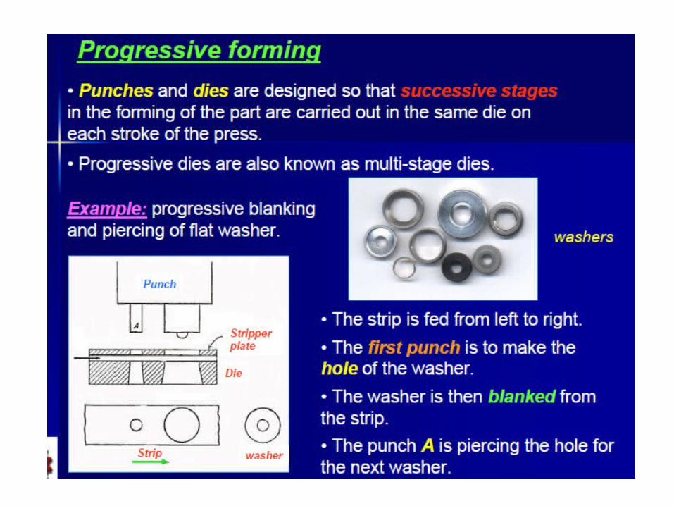
Type • Inverted die: convention die• Progressive die: two or more operation at
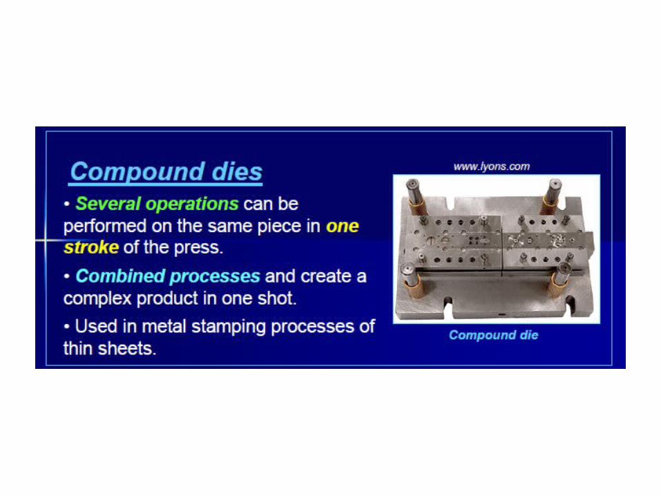
different stage every time• Compound die: two or more operation during
one stroke at one station• Combination die: combine with non cutting
operation with cutting operation• Steel rules: originally develop for paper box
industries later principle applies to gaskets, auto body parts etc


• Rubber pad blanking: to transmit the pressure in all the direction
• Used for aluminum alloy • Fine blanking: produce smooth edges and
closed wall thichness


cutting action in punch and die operations
• Rollover radius-depends on ductility of the material
• Edge radius produce during initial stage of plastic deformation and it is more pronounced in soft material
• The sum of edge radius depth and burnished depth is referred as penetration

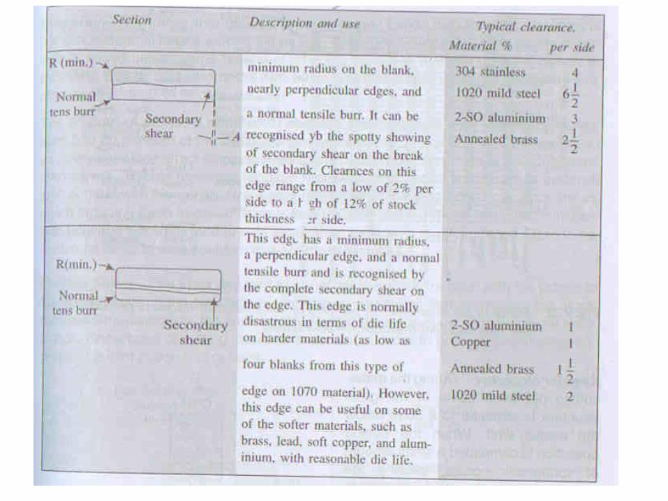
Die clearance
• Clearance is necessary to allow the fracture to meet when break occurs
• Excessive clearance large burrs• Insufficient cause miss and prevent the clean
break


DESIGN RULES
• For parts that are to be manufactured with dedicated dies, design outer profile with parallel straight edges defining part width.
• To allow for satisfactory shearing in cut-off or part-off operations, end profiles should meet straight edges at angles no less than 15°.
04/18/2023 06:52 AM

DESIGN RULES
• No narrow projections or notches that will require narrow weak sections in either punches or die plates (dimensions marked "a" in Fig. 9.27)
04/18/2023 06:52 AM

DESIGN RULES
• Avoid Small holes or narrow cut-outs that will require fragile punches.
• Internal punched holes should be separated from each other, and from outside edge, with sufficient clearance to avoid distortion of narrow sections of work-piece material during punching.
04/18/2023 06:52 AM

DESIGN RULES
• Both feature dimensions and feature spacings should be at least twice material thickness.
• Fig. 9.27, satisfactory blanking and punching will require that dimensions labeled "a" through "d" should all be greater than or equal to twice gage thickness.
04/18/2023 06:52 AM

DESIGN RULES
• "e“, corner radii in die plate: Radii equal to at least twice gage thickness will minimize corner stress concentrations in die plate, which may lead to crack formation and failure.
04/18/2023 06:52 AM 35

DESIGN RULES• Incorporate relief cut-outs
dimensioned as "d," at ends of proposed bend lines that terminate at internal corners in outer profile.
• If for any reason holes that intersect outer profile must be punched later, then diameter should be at least three times gage thickness to accommodate offset loading to which punch will be subjected.
04/18/2023 06:52 AM
DESIGN RULES
• When formed features are being considered, principal design constraint is max tensile strain the material can withstand.
• Fig. 9.28:– component made from low-carbon,
commercial-quality steel– Transition from surface to top of bridge =
45°.
04/18/2023 06:52 AM

DESIGN RULES
04/18/2023 06:52 AM
DESIGN RULES
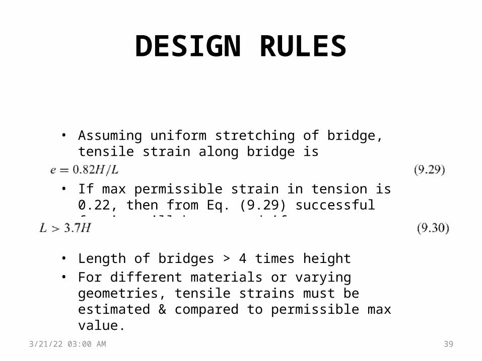
• Assuming uniform stretching of bridge, tensile strain along bridge is
• If max permissible strain in tension is 0.22, then from Eq. (9.29) successful forming will be assured if
• Length of bridges > 4 times height• For different materials or varying geometries, tensile strains
must be estimated & compared to permissible max value.
04/18/2023 06:52 AM 39

DESIGN RULES
Louver (Figure 9.29):• Length of front edge must
be greater than a certain multiple of louver opening height H, determined by material ductility and end ramp angles exactly as in the bridge calculation.
04/18/2023 06:52 AM 40

DESIGN RULES
• Stretching also occurs at right angles to louver edge where material is stretched upward into a circular arc.
• This will not cause material failure, since front edge of louver will be pulled backward as tensile stress develops in the surface.
• Choice of radius R (Fig. 9.29) is more one of appearance and amount of space taken up by a single louver.
04/18/2023 06:52 AM 41

DESIGN RULESHole flange (Figure 9.30)
• Hole flanging: provide increased local thickness for tapping of screw threads
• Hole flange is formed by pressing a taper-nosed punch of diameter D into a smaller punched hole of diameter d.
• Tensile strain around top edge of formed flange is
04/18/2023 06:52 AM 42

DESIGN RULESHole flange (Figure 9.30)
• e < permissible material ductility• Typical values of flange height in
sheet steel components range between 2 and 3 times material gage thickness.
04/18/2023 06:52 AM 43
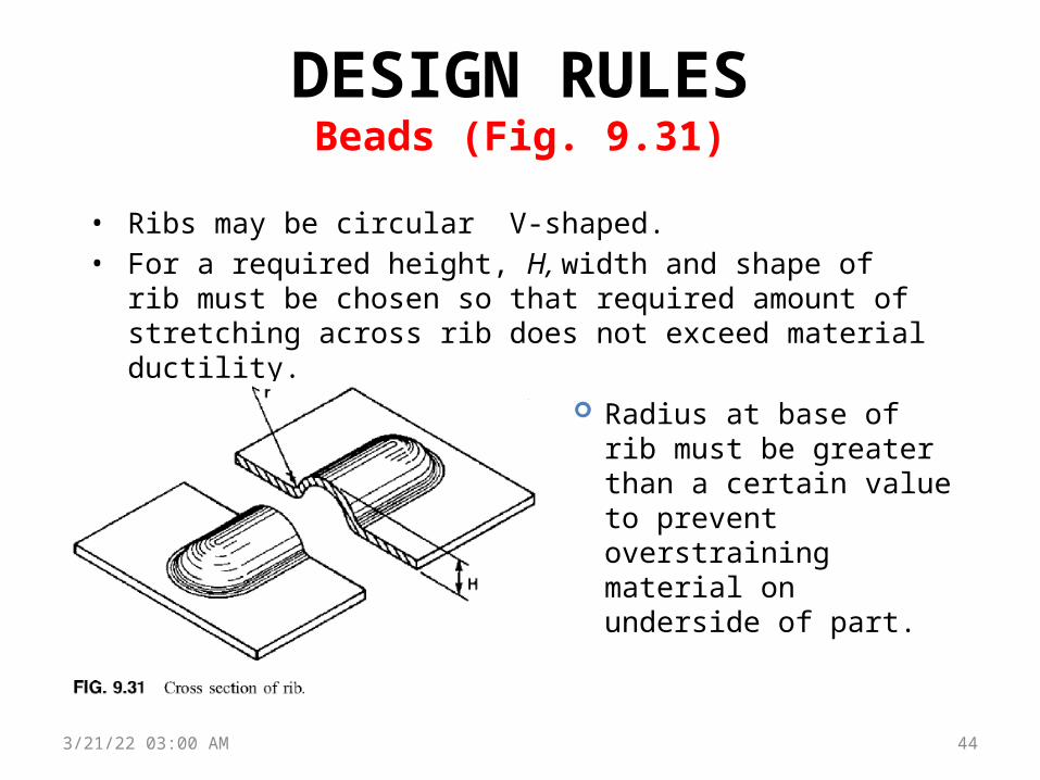
DESIGN RULESBeads (Fig. 9.31)
• Ribs may be circular V-shaped.• For a required height, H, width and shape of rib must be chosen so
that required amount of stretching across rib does not exceed material ductility.
04/18/2023 06:52 AM 44
Radius at base of rib must be greater than a certain value to prevent overstraining material on underside of part.

DESIGN RULESBeads (Fig. 9.31)
• Max tensile strain in bending is in the outer fibers of the sheet on the outside of the bend and is governed by the ratio of inside bend radius, r, to sheet gage thickness, h.
• For a bend through any angle q, length of outer surface is
• length of surface in center of sheet (neutral axis) is
• strain on outer surface is
• Radius r is defined precisely by profile radius of bending tool:• convex radius of die block for a wiper die• convex radius of punch in a v-die.
04/18/2023 06:52 AM 45

DESIGN RULESBeads (Fig. 9.31)
• Min acceptable radius value can be obtained from Eq. (9.34) and ductility of material to be bent.
• Example: low-carbon, commercial-quality steel with ductility 0.22, Eq. (9.34) gives
• Inside bend radius ≥ twice sheet thickness (limiting value for a material with 20% ductility)
04/18/2023 06:52 AM 46
DESIGN RULES
04/18/2023 06:52 AM 47
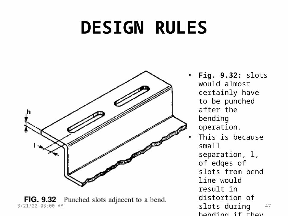
• Fig. 9.32: slots would almost certainly have to be punched after the bending operation.
• This is because small separation, l, of edges of slots from bend line would result in distortion of slots during bending if they were punched first.

DESIGN RULES
• If part contains other holes or slots that are now on nonparallel surfaces to the one shown, then two separate dies and operations are needed for punching where one would otherwise have been sufficient.
• Edge of circular holes should preferably be 2 times sheet thickness from beginning of a bend.
• For slots parallel to a bend this clearance should increase to 4 times sheet thickness.
04/18/2023 06:52 AM 48

DESIGN RULES• Blanked parts or punched holes with max dimensions up
to 10cm can be held to tolerances of around ±0.05 mm• As part size increases, precision is more difficult to
control• For a part with dimensions as large as 50 cm permissible
tolerances are in the range of ±0.5 mm.• For formed parts, or formed features, variation tends to
be larger and minimum tolerances attainable are in the range of ±0.25 mm for small parts.
• A tight tolerance between punched holes, which are on parallel surfaces separated by bends, would require holes to be punched after bending at greater expense.
• If holes are on nonparallel surfaces, then machining may be necessary to obtain required accuracy.
04/18/2023 06:52 AM 49

DESIGN RULESMinimization of manufactured scrap
• nesting• If individual dies are to be used, then part should be designed if possible for
cut-off or part-off operations.• Figure 9.33:
– cut-off design lacks elegance of rounded end profiles.– acute sharp corner will be removed during debarring
04/18/2023 06:52 AM 50

Die design fundamentals• Blanking and piercing die construction
– Screws and dowels: dies are held together by socket-head cap screws and held in dowel pins
– Dowel pins located diagonally 1.5 to 2 times of diameter
– Die-block design: design of the die block depends upon the workpiece size and thickness.
– punch design: depends upon the area to be pierced or blanked and the pressure required to penetrate the work material.
– Types of punches: plain punches, pedestal punches, perforator punches

• Method of mounting punches: punch support, punch shedder
• Pilots: the function of pilots is to position the stock strip accurately and bring it into proper register for succeeding blanking and piercing operations
• Strippers and pressure pads: channel stripper, spring-operated stripers

Selection of stripper
• P = tlk N• Stripping force is 10% of cutting force