ch: self-lubricating thrust/journal bearings
TRANSCRIPT
K I N G S B U R Y B E A R I N G S Y S T E M S
CHampC
TABLE OF CONTENTS
INTRODUCTION 3
ADVANTAGES OF KINGSBURYrsquoSCH SYSTEM 4
GENERAL DESCRIPTION 6
HOW THE CH LUBRICATION SYSTEM WORKS 8
BEARING SELECTION 10
CH BEARING DIMENSIONAL DATA 12
C BEARING DIMENSIONAL DATA 13
PERFORMANCE DATACURVES 14
OPTIONS AND INSTRUMENTATION 18
The Kingsbury CH Bearing System integrates a fully self-contained flange-
mounted horizontal equalizing double thrust bearing with a self-aligning journal
bearing (CH) and a remote separately mounted journal bearing (C)
At the heart of every CH unit is a self-contained load-equalizing thrust bearing
The system eliminates the need for an electric motor pump emergency pump
accumulator rundown tank or other special arrangements for oil lubrication No
additional motor control system or any electric power is required to circulate the
oil And since no separate lube system is required the cost savings are significant
System lubrication is autonomous provided by means of a viscosity pump
driven by shaft rotation This pump consists of the combination of the built-in
mechanical oil circulator and the rotating collar which draws oil up from the sump
as soon as the shaft begins to rotate As long as the shaft rotates pumping action is
achieved No priming is necessary since the pump inlets are always submerged
Pumping action is bidirectional and automatically adjusts with shaft rotation
The pressure and flow generated by this pump force the oil out through
passages in the housing to lubricate both thrust bearings and the internal journal
bearing The pressure in the thrust cavity then drives the hot oil through the oil
cooler and then back into the oil sump The fewer the restrictions in the system
the more the circulator can pump
Sufficient flow and pressure are developed by the CH unit that it can be
evaluated for supplying oil to a separate remote journal bearing for example the
system prime mover Please contact your Kingsbury Sales Engineer if you wish to
have the CH lubricate additional equipment
3
QUALITY STANDARDS
KINGSBURY INC ISO 9001 2008 Registered
4
ADVANTAGES OF KINGSBURYrsquoSCH SYSTEM
Only Kingsburyrsquos CH BearingSystem integrates 1) a non-drive-end (NDE) unitwith a double equalizing thrustbearing a journal bearing and anoil circulator within a single
unified housing and 2) a drive-end (DE) unit with an integraljournal bearing in a second housing of its own Other designsnecessitate purchasing thrust andjournal bearings separately and
then still require additional components like a machinedhousing and external lubricationsystem
The Kingsbury CH system is integrated reliable and saves
CH UNIT
C UNIT
5
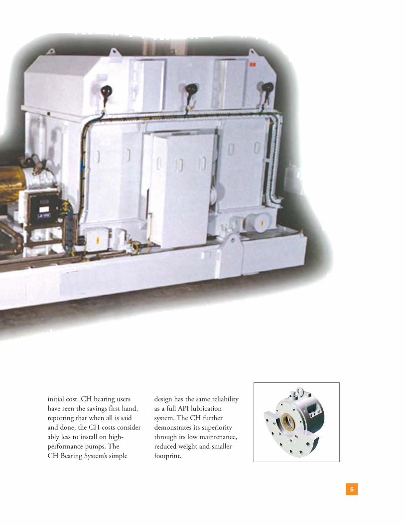
initial cost CH bearing usershave seen the savings first handreporting that when all is saidand done the CH costs consider-ably less to install on high-performance pumps The CH Bearing Systemrsquos simple
design has the same reliabilityas a full API lubrication system The CH further demonstrates its superioritythrough its low maintenancereduced weight and smaller footprint
CH SystemKingsburyrsquos complete CH system includes two separatecomponents the CH unit whichincludes thrust and journal bear-ings and provides the lubricationand the C unit with a remotely mounted journal bearing
CH UnitThrust BearingsKingsbury utilizes equalizingthrust bearings which conform to API 610 requirements TheKingsbury principle and theworkings of the equalizing thrustbearing are fully described in ourEQH-1 catalog
Journal Bearing
The CH unit contains an integral self-aligning journalbearing designed to accuratelylocate the shaft under all loadingconditions Journal bearing diam-eters are based on the machinersquosshaft requirements Each housingwill accommodate a choice ofthree standard journal bearingdiameters listed on pages 12through 15 If the shaft cannot bemachined to one of the standarddiameters Kingsbury offers at amodest fee the option of a custom-designed journal bearingto accommodate the shaft
C UnitAlso available are separate self-aligning journal bearings Thesemodel C bearings are assigned
designations similar to the CHunit Typically at the inboard(drive) end of the machine theyare generally of the same designand size as the journal in the CHunit These bearings depend onthe CH bearing for lubricationC bearing units may be purchased separately but requirean external lubrication system if aCH unit is not incorporated Toensure proper lubrication thepiping to and from these bearingsshould conform to Kingsburyrsquosguidelines as described underldquoOil Pipingrdquo page 10
Oil CirculatorThe oil circulator is the heart ofKingsburyrsquos CH system Workingin concert with the thrust collar toform a self-priming viscositypump it provides lubrication tothe entire system by means ofshaft rotation As long as the shaftis rotating pressurized oil is avail-able even during power outages orreverse rotation It may even pro-vide sufficient volume and pressureto lubricate additional externallymounted equipment such asmotor bearings or couplingsPlease consult one of Kingsburyrsquossales engineers for an evaluation ofyour application
GENERAL DESCRIPTION
6
7
JOURNAL BEARING
LABYRINTH END SEAL
OIL SEAL RING
THRUST BEARING (OUTBOARD SHOWNINBOARD BEARINGREMOVED FOR CLARITY)
CoolingStandard oil cooling is providedby means of a plate-style heatexchanger mounted directly onthe CH unit and requires freshwater typically supplied at a temperature of 30deg C (85deg F)Standard coolers can be providedto suit any speed within the catalogrsquos published load andspeed ranges Shell-and-tube heatexchangers are also available for applications with special coolants
such as sea water as is the option of forced-air cooling See page 11for additional information on oilcooling
Standard SizesCapacitiesStandard units listed in this catalogcan accommodate thrust loads upto 180 kN (40000 lbf) shaft sizesup to 190 mm (750rdquo) and slidingvelocities up to 65 ms (215 ftsec)at the mean diameter of the thrustcollar
Custom DesignsThe self-lubricating system hasbeen incorporated successfully inapplications larger than those listed in this catalog includingpedestal-mounted housings formarine dredge pumps Pleaseconsult our Sales Department for information on sizes andorequipment not listed here
OIL CIRCULATOR
HOW THE CH BEARING LUBRICATION SYSTEM WORKS
8
As the shaft begins to rotate oil is drawnfrom the reservoir through a port in the oil circulator
Cool oil travels around both thrust bearings as well a channel toward theintegral journal bearing
Pressurized oil from the central passage of the circulator enters the thrust bearings to be drawn across the shoes
At the same time oil passes through the thrust bearings pressurized oilflows around the journal bearing
To view oil flow animations online click on an image below Animations will open in a new tabwindow
9
Hot oil from the thrust bearings returns tothe heat exchanger through a standpipe
As pressurized oil is supplied to the integral journal in the CH unit it also travels to the journal in the remote C bearing Hot oil returns to thereservoir by customer-supplied piping
As pressurized oil is supplied to the integral journal in the CH unit it also travels to the journal in the remote C bearing Hot oil returns to thereservoir by customer-supplied piping
10
BEARING SELECTIONGuidelines for assigning loadcapacities take several factorsinto consideration includingtheoretical analyses our fieldexperience and test resultsThrust bearing rated loads (page14 or 15) have been calculatedbased on the following designconsiderations on low-speedapplications the limiting factoris film thickness on high-speedapplications the limiting factoris shoe temperatureAll the ratings published in thiscatalog have a factor of safety ofat least twoThis complies with standardindustry specifications includingthose of the American PetroleumInstitute
For most typical applicationsthe determining factor in selectinga CH unit size is the requiredshaft diameter
1 Using the shaft size limitsindicated in our catalog draw-ings determine the smallest CHunit that accommodates yourshaft size
2 Next check the bearingthrust capacities versus requiredload demands The selected unitshould be capable of handling themaximum thrust load Use thefollowing figures as a guide
bull See page 14 or 15 for the Thrust Bearing Rated Load curve for ISO VG 46bull See page 16 or 17 for theThrust Bearings Friction Loss curve3 Finally confirm the
journal load capacity from
page 16 or 18Example Given a thrust load
of 20000 N (4500 lbsf ) shaftdiameter at the journal of 80mm (315rdquo) a speed of 3600rpm and a journal load of 8000N (1800 lbsf )
Selection From the tables onpages 12-13 select the smallestunit size with the correct shaftdiameter The smallest unit capa-ble of handling the given shaft isa CH-1 Next refer to ThrustBearing Rated Load curve page14 or 15 to confirm that theCH-1 is acceptable Note that itis more than adequate for thegiven thrust load Finally verifyfrom Journal Bearing RatedLoad curve page 14 or 15 thatthe journal size is adequate forthe specified load Therefore aCH-1 will be the best solution for the given data
Oil PipingOil piping between the remote Cand the CH is not supplied by
Kingsbury Piping should bearranged with the C bearingreturn pipe going straight downfar enough to give a continuousrise at a slope of between 5deg and8deg to the CH unit As the headpressure on the returning oil isslight the return pipe must beadequately sized Please refer toSheet 1 of the C unit drawing(link on page 13) to determinethe proper size All oil pipingmust be installed well below theoil level Trace heating on pipesand an oil heater in the CHsump are recommended if ambi-ent temperatures are likely to gobelow 10deg C (50deg F) at startup
Oil CoolingThe integral heat exchangerrsquosunique design combines a highthermal efficiency with a mini-mal pressure drop Optionalarrangements include an allbrassbronze construction forseawater-cooling applicationsand an all-ASTM A300-seriesstainless-steel construction For
Photo copyright Sulzer Ltda Jundiai Brazil
stainless-steel construction Forapplications in which no coolingwater is available a forced-air oilcooler can be provided Only thestandard cooler and the all-brasscoolers can be mounted directlyto the CH unit All other optionsmust be remotely mounted asclose as possible to the CH bear-ing When the cooling water isthermostatically controlled theflow rate must be set to maintainthe sump at 50deg C (120deg F) orthe temperature specified
Oil SelectionThe charts and tables in this cata-log are based on an oil viscositygrade of ISO VG 46 Howeverother oil viscosity grades can beused Their use is based largely onspeed and load considerations Forexample ISO VG 32 is better suited for light loads andor highspeeds whereas ISO VG 68should be used if the loads arehigher and the speeds slower Ifunsure of the best oil viscosity foryour application please consultKingsbury for a recommendation
Since the Kingsbury CHBearing System is entirely self-con-tained continuous filtration is notrequired Initial oil fill is to be fil-tered to 10 microns or better SeeTable on pages 12 to 13 for CHhousing oil sump capacities Pleaseadd a sufficient amount of oil tothese capacities to allow for theapplicationrsquos piping
Caution The piping canusually accommodate more oilthan the sump itself
Flange OptionsKingsburyrsquos CH and C units aredesigned to give the customerconsiderable flexibility whenselecting the type of flange forthe application The flange isdesigned and machined separatelyfrom the housing and can beeither a half or full circle withthe bolt circle of your choice Seeindividual drawings for moredetails on flange selection
Shaft and Collar DetailsTypically Kingsbury will supplya separate thrust collar We rec-ommend that the collars have asliding fit (ANSI Class RC2) onthe shaft User must provide theshaft nut nut locking device and key Details of the arrangement
are shown on the individualdrawings Details of the arrangement are on page 13
PaintAll units come painted on theexterior with a gray metal primerand the internal unmachined oil-containing surfaces painted withan insulating enamel Attachedcoolers come painted with a styre-nated alkyd enamel All exteriorsurfaces that are painted can bere-coated
11
CH BEARINGDIMENSIONAL DATA
To view detailed dimension drawings visit httpkingsburycomfile_libraryshtml
CH Bearing Size 160 mm ndash 70 mm ndash 80 mm
CH Bearing Size 3110 mm ndash 130 mm ndash 150 mm
CH Bearing Size 280 mm ndash 95 mm ndash 110 mm
CH Bearing Size 4150 mm ndash 170 mm ndash 190 mm
12
C BEARINGDIMENSIONAL DATA
A
A
B
B
350deg 350deg
450deg
12X HOLES FULL FLANGE MOUNTING THRU HOLE Oslash
CBORE DIA Oslash CBORE DEPTH (FARSIDE)EQUALLY SPACED(SEE TABLE B)
EYEBOLT FOR HANDLING
1520 [598]
MOUNTING HOLE BOLT CIRCLE(SEE TABLE B)
15deg
30deg 12X
To view detailed dimension drawings visit httpkingsburycomfile_libraryshtml
C Bearing Size 160 mm ndash 70 mm ndash 80 mm
C Bearing Size 3110 mm ndash 130 mm ndash 150 mm
C Bearing Size 280 mm ndash 95 mm ndash 110 mm
C Bearing Size 4150 mm ndash 170 mm ndash 190 mm
13
14
RATED LOAD FOR CH SYSTEM JOURNAL BEARINGS (METRIC)
RATED LOAD FOR CH SYSTEM THRUST BEARINGS (METRIC)
Based on ISO VG 46 oil at 49degC sump temperature at the journal mean diameter
Based on ISO VG 46 oil at 49degC sump temperature
PERFORMANCE DATA CURVES
15
RATED LOAD FOR CH SYSTEM JOURNAL BEARINGS (AMERICAN STANDARD)
RATED LOAD FOR CH SYSTEM THRUST BEARINGS (AMERICAN STANDARD)
Based on ISO VG 46 oil at 120˚F sump temperature at the journal mean diameter
Based on ISO VG 46 oil at 120˚F sump temperature
16
RECOMMENDED COOLING WATER FLOW FOR CH SYSTEM (METRIC)
TOTAL FRICTIONAL LOSS FOR CH SYSTEM (METRIC)
Based on rated loads standard cooler ISO VG 46 oil at 49degC inlet 27˚C cooling water
Based on rated thrust and journal loads ISO VG 46 oil 49degC sump temperature
17
RECOMMENDED COOLING WATER FLOW FOR CH SYSTEM (AMERICAN STANDARD)
TOTAL FRICTIONAL LOSS FOR CH SYSTEM (AMERICAN STANDARD)
Based on rated loads standard cooler ISO VG 46 oil at 120˚F inlet 80˚F cooling water
Based on rated thrust and journal loads ISO VG 46 oil 120˚F sump temperature
18
OPTIONS AND INSTRUMENTATION
BASIC MODELStandard CH and C units aresupplied with the option of a halfor full flange a flat or spigotmount labyrinth or Inproreg endseals as well as provisions fortemperature detectors axial andradial vibration probes and lift-ing bolts Each housing configu-ration allows for three standardshaft diameters which can beadapted to accommodate specialcustomer requirements if neces-sary Please refer to the drawingson pages 12 to 13 for all stan-dardized options
INSTRUMENTATIONInstrumentation taps can be provided for temperature sensingvibration monitoring and phasereference monitoring Please seethe callouts indicated on the pho-tos for tap options and locationsKingsbury can also provideinstrumentation if requested
RADIAL VIBRATIONTAP (ONE OF TWO)
THRUST BEARING RTDTHERMOCOUPLE TAPS
OPTIONAL HEATERTAP (NOT SHOWN)
AXIAL (THRUST)PROBE TAP(S)
STANDARDOIL COOLER
OIL SUMPTHERMOWELLTAP
JOURNAL BEARINGOIL RETURN
TIMING AND PHASEREFERENCE TAP
RADIALVIBRATIONPROBE TAP
BEARING ISOLATOR
HALFMOUNTINGFLANGESHOWN(FULL FLANGEOPTIONAL)
CH UNIT
C UNIT
RTDTHERMOCOUPLE TAP (IN BOTTOM NOT SHOWN
10385 Drummond RoadPhiladelphia PA 19154 USA Telephone +1 215-824-4000Fax +1 215-824-4999wwwkingsburycom

TABLE OF CONTENTS
INTRODUCTION 3
ADVANTAGES OF KINGSBURYrsquoSCH SYSTEM 4
GENERAL DESCRIPTION 6
HOW THE CH LUBRICATION SYSTEM WORKS 8
BEARING SELECTION 10
CH BEARING DIMENSIONAL DATA 12
C BEARING DIMENSIONAL DATA 13
PERFORMANCE DATACURVES 14
OPTIONS AND INSTRUMENTATION 18
The Kingsbury CH Bearing System integrates a fully self-contained flange-
mounted horizontal equalizing double thrust bearing with a self-aligning journal
bearing (CH) and a remote separately mounted journal bearing (C)
At the heart of every CH unit is a self-contained load-equalizing thrust bearing
The system eliminates the need for an electric motor pump emergency pump
accumulator rundown tank or other special arrangements for oil lubrication No
additional motor control system or any electric power is required to circulate the
oil And since no separate lube system is required the cost savings are significant
System lubrication is autonomous provided by means of a viscosity pump
driven by shaft rotation This pump consists of the combination of the built-in
mechanical oil circulator and the rotating collar which draws oil up from the sump
as soon as the shaft begins to rotate As long as the shaft rotates pumping action is
achieved No priming is necessary since the pump inlets are always submerged
Pumping action is bidirectional and automatically adjusts with shaft rotation
The pressure and flow generated by this pump force the oil out through
passages in the housing to lubricate both thrust bearings and the internal journal
bearing The pressure in the thrust cavity then drives the hot oil through the oil
cooler and then back into the oil sump The fewer the restrictions in the system
the more the circulator can pump
Sufficient flow and pressure are developed by the CH unit that it can be
evaluated for supplying oil to a separate remote journal bearing for example the
system prime mover Please contact your Kingsbury Sales Engineer if you wish to
have the CH lubricate additional equipment
3
QUALITY STANDARDS
KINGSBURY INC ISO 9001 2008 Registered
4
ADVANTAGES OF KINGSBURYrsquoSCH SYSTEM
Only Kingsburyrsquos CH BearingSystem integrates 1) a non-drive-end (NDE) unitwith a double equalizing thrustbearing a journal bearing and anoil circulator within a single
unified housing and 2) a drive-end (DE) unit with an integraljournal bearing in a second housing of its own Other designsnecessitate purchasing thrust andjournal bearings separately and
then still require additional components like a machinedhousing and external lubricationsystem
The Kingsbury CH system is integrated reliable and saves
CH UNIT
C UNIT
5
initial cost CH bearing usershave seen the savings first handreporting that when all is saidand done the CH costs consider-ably less to install on high-performance pumps The CH Bearing Systemrsquos simple
design has the same reliabilityas a full API lubrication system The CH further demonstrates its superioritythrough its low maintenancereduced weight and smaller footprint
CH SystemKingsburyrsquos complete CH system includes two separatecomponents the CH unit whichincludes thrust and journal bear-ings and provides the lubricationand the C unit with a remotely mounted journal bearing
CH UnitThrust BearingsKingsbury utilizes equalizingthrust bearings which conform to API 610 requirements TheKingsbury principle and theworkings of the equalizing thrustbearing are fully described in ourEQH-1 catalog
Journal Bearing
The CH unit contains an integral self-aligning journalbearing designed to accuratelylocate the shaft under all loadingconditions Journal bearing diam-eters are based on the machinersquosshaft requirements Each housingwill accommodate a choice ofthree standard journal bearingdiameters listed on pages 12through 15 If the shaft cannot bemachined to one of the standarddiameters Kingsbury offers at amodest fee the option of a custom-designed journal bearingto accommodate the shaft
C UnitAlso available are separate self-aligning journal bearings Thesemodel C bearings are assigned
designations similar to the CHunit Typically at the inboard(drive) end of the machine theyare generally of the same designand size as the journal in the CHunit These bearings depend onthe CH bearing for lubricationC bearing units may be purchased separately but requirean external lubrication system if aCH unit is not incorporated Toensure proper lubrication thepiping to and from these bearingsshould conform to Kingsburyrsquosguidelines as described underldquoOil Pipingrdquo page 10
Oil CirculatorThe oil circulator is the heart ofKingsburyrsquos CH system Workingin concert with the thrust collar toform a self-priming viscositypump it provides lubrication tothe entire system by means ofshaft rotation As long as the shaftis rotating pressurized oil is avail-able even during power outages orreverse rotation It may even pro-vide sufficient volume and pressureto lubricate additional externallymounted equipment such asmotor bearings or couplingsPlease consult one of Kingsburyrsquossales engineers for an evaluation ofyour application
GENERAL DESCRIPTION
6
7
JOURNAL BEARING
LABYRINTH END SEAL
OIL SEAL RING
THRUST BEARING (OUTBOARD SHOWNINBOARD BEARINGREMOVED FOR CLARITY)
CoolingStandard oil cooling is providedby means of a plate-style heatexchanger mounted directly onthe CH unit and requires freshwater typically supplied at a temperature of 30deg C (85deg F)Standard coolers can be providedto suit any speed within the catalogrsquos published load andspeed ranges Shell-and-tube heatexchangers are also available for applications with special coolants
such as sea water as is the option of forced-air cooling See page 11for additional information on oilcooling
Standard SizesCapacitiesStandard units listed in this catalogcan accommodate thrust loads upto 180 kN (40000 lbf) shaft sizesup to 190 mm (750rdquo) and slidingvelocities up to 65 ms (215 ftsec)at the mean diameter of the thrustcollar
Custom DesignsThe self-lubricating system hasbeen incorporated successfully inapplications larger than those listed in this catalog includingpedestal-mounted housings formarine dredge pumps Pleaseconsult our Sales Department for information on sizes andorequipment not listed here
OIL CIRCULATOR
HOW THE CH BEARING LUBRICATION SYSTEM WORKS
8
As the shaft begins to rotate oil is drawnfrom the reservoir through a port in the oil circulator
Cool oil travels around both thrust bearings as well a channel toward theintegral journal bearing
Pressurized oil from the central passage of the circulator enters the thrust bearings to be drawn across the shoes
At the same time oil passes through the thrust bearings pressurized oilflows around the journal bearing
To view oil flow animations online click on an image below Animations will open in a new tabwindow
9
Hot oil from the thrust bearings returns tothe heat exchanger through a standpipe
As pressurized oil is supplied to the integral journal in the CH unit it also travels to the journal in the remote C bearing Hot oil returns to thereservoir by customer-supplied piping
As pressurized oil is supplied to the integral journal in the CH unit it also travels to the journal in the remote C bearing Hot oil returns to thereservoir by customer-supplied piping
10
BEARING SELECTIONGuidelines for assigning loadcapacities take several factorsinto consideration includingtheoretical analyses our fieldexperience and test resultsThrust bearing rated loads (page14 or 15) have been calculatedbased on the following designconsiderations on low-speedapplications the limiting factoris film thickness on high-speedapplications the limiting factoris shoe temperatureAll the ratings published in thiscatalog have a factor of safety ofat least twoThis complies with standardindustry specifications includingthose of the American PetroleumInstitute
For most typical applicationsthe determining factor in selectinga CH unit size is the requiredshaft diameter
1 Using the shaft size limitsindicated in our catalog draw-ings determine the smallest CHunit that accommodates yourshaft size
2 Next check the bearingthrust capacities versus requiredload demands The selected unitshould be capable of handling themaximum thrust load Use thefollowing figures as a guide
bull See page 14 or 15 for the Thrust Bearing Rated Load curve for ISO VG 46bull See page 16 or 17 for theThrust Bearings Friction Loss curve3 Finally confirm the
journal load capacity from
page 16 or 18Example Given a thrust load
of 20000 N (4500 lbsf ) shaftdiameter at the journal of 80mm (315rdquo) a speed of 3600rpm and a journal load of 8000N (1800 lbsf )
Selection From the tables onpages 12-13 select the smallestunit size with the correct shaftdiameter The smallest unit capa-ble of handling the given shaft isa CH-1 Next refer to ThrustBearing Rated Load curve page14 or 15 to confirm that theCH-1 is acceptable Note that itis more than adequate for thegiven thrust load Finally verifyfrom Journal Bearing RatedLoad curve page 14 or 15 thatthe journal size is adequate forthe specified load Therefore aCH-1 will be the best solution for the given data
Oil PipingOil piping between the remote Cand the CH is not supplied by
Kingsbury Piping should bearranged with the C bearingreturn pipe going straight downfar enough to give a continuousrise at a slope of between 5deg and8deg to the CH unit As the headpressure on the returning oil isslight the return pipe must beadequately sized Please refer toSheet 1 of the C unit drawing(link on page 13) to determinethe proper size All oil pipingmust be installed well below theoil level Trace heating on pipesand an oil heater in the CHsump are recommended if ambi-ent temperatures are likely to gobelow 10deg C (50deg F) at startup
Oil CoolingThe integral heat exchangerrsquosunique design combines a highthermal efficiency with a mini-mal pressure drop Optionalarrangements include an allbrassbronze construction forseawater-cooling applicationsand an all-ASTM A300-seriesstainless-steel construction For
Photo copyright Sulzer Ltda Jundiai Brazil
stainless-steel construction Forapplications in which no coolingwater is available a forced-air oilcooler can be provided Only thestandard cooler and the all-brasscoolers can be mounted directlyto the CH unit All other optionsmust be remotely mounted asclose as possible to the CH bear-ing When the cooling water isthermostatically controlled theflow rate must be set to maintainthe sump at 50deg C (120deg F) orthe temperature specified
Oil SelectionThe charts and tables in this cata-log are based on an oil viscositygrade of ISO VG 46 Howeverother oil viscosity grades can beused Their use is based largely onspeed and load considerations Forexample ISO VG 32 is better suited for light loads andor highspeeds whereas ISO VG 68should be used if the loads arehigher and the speeds slower Ifunsure of the best oil viscosity foryour application please consultKingsbury for a recommendation
Since the Kingsbury CHBearing System is entirely self-con-tained continuous filtration is notrequired Initial oil fill is to be fil-tered to 10 microns or better SeeTable on pages 12 to 13 for CHhousing oil sump capacities Pleaseadd a sufficient amount of oil tothese capacities to allow for theapplicationrsquos piping
Caution The piping canusually accommodate more oilthan the sump itself
Flange OptionsKingsburyrsquos CH and C units aredesigned to give the customerconsiderable flexibility whenselecting the type of flange forthe application The flange isdesigned and machined separatelyfrom the housing and can beeither a half or full circle withthe bolt circle of your choice Seeindividual drawings for moredetails on flange selection
Shaft and Collar DetailsTypically Kingsbury will supplya separate thrust collar We rec-ommend that the collars have asliding fit (ANSI Class RC2) onthe shaft User must provide theshaft nut nut locking device and key Details of the arrangement
are shown on the individualdrawings Details of the arrangement are on page 13
PaintAll units come painted on theexterior with a gray metal primerand the internal unmachined oil-containing surfaces painted withan insulating enamel Attachedcoolers come painted with a styre-nated alkyd enamel All exteriorsurfaces that are painted can bere-coated
11
CH BEARINGDIMENSIONAL DATA
To view detailed dimension drawings visit httpkingsburycomfile_libraryshtml
CH Bearing Size 160 mm ndash 70 mm ndash 80 mm
CH Bearing Size 3110 mm ndash 130 mm ndash 150 mm
CH Bearing Size 280 mm ndash 95 mm ndash 110 mm
CH Bearing Size 4150 mm ndash 170 mm ndash 190 mm
12
C BEARINGDIMENSIONAL DATA
A
A
B
B
350deg 350deg
450deg
12X HOLES FULL FLANGE MOUNTING THRU HOLE Oslash
CBORE DIA Oslash CBORE DEPTH (FARSIDE)EQUALLY SPACED(SEE TABLE B)
EYEBOLT FOR HANDLING
1520 [598]
MOUNTING HOLE BOLT CIRCLE(SEE TABLE B)
15deg
30deg 12X
To view detailed dimension drawings visit httpkingsburycomfile_libraryshtml
C Bearing Size 160 mm ndash 70 mm ndash 80 mm
C Bearing Size 3110 mm ndash 130 mm ndash 150 mm
C Bearing Size 280 mm ndash 95 mm ndash 110 mm
C Bearing Size 4150 mm ndash 170 mm ndash 190 mm
13
14
RATED LOAD FOR CH SYSTEM JOURNAL BEARINGS (METRIC)
RATED LOAD FOR CH SYSTEM THRUST BEARINGS (METRIC)
Based on ISO VG 46 oil at 49degC sump temperature at the journal mean diameter
Based on ISO VG 46 oil at 49degC sump temperature
PERFORMANCE DATA CURVES
15
RATED LOAD FOR CH SYSTEM JOURNAL BEARINGS (AMERICAN STANDARD)
RATED LOAD FOR CH SYSTEM THRUST BEARINGS (AMERICAN STANDARD)
Based on ISO VG 46 oil at 120˚F sump temperature at the journal mean diameter
Based on ISO VG 46 oil at 120˚F sump temperature
16
RECOMMENDED COOLING WATER FLOW FOR CH SYSTEM (METRIC)
TOTAL FRICTIONAL LOSS FOR CH SYSTEM (METRIC)
Based on rated loads standard cooler ISO VG 46 oil at 49degC inlet 27˚C cooling water
Based on rated thrust and journal loads ISO VG 46 oil 49degC sump temperature
17
RECOMMENDED COOLING WATER FLOW FOR CH SYSTEM (AMERICAN STANDARD)
TOTAL FRICTIONAL LOSS FOR CH SYSTEM (AMERICAN STANDARD)
Based on rated loads standard cooler ISO VG 46 oil at 120˚F inlet 80˚F cooling water
Based on rated thrust and journal loads ISO VG 46 oil 120˚F sump temperature
18
OPTIONS AND INSTRUMENTATION
BASIC MODELStandard CH and C units aresupplied with the option of a halfor full flange a flat or spigotmount labyrinth or Inproreg endseals as well as provisions fortemperature detectors axial andradial vibration probes and lift-ing bolts Each housing configu-ration allows for three standardshaft diameters which can beadapted to accommodate specialcustomer requirements if neces-sary Please refer to the drawingson pages 12 to 13 for all stan-dardized options
INSTRUMENTATIONInstrumentation taps can be provided for temperature sensingvibration monitoring and phasereference monitoring Please seethe callouts indicated on the pho-tos for tap options and locationsKingsbury can also provideinstrumentation if requested
RADIAL VIBRATIONTAP (ONE OF TWO)
THRUST BEARING RTDTHERMOCOUPLE TAPS
OPTIONAL HEATERTAP (NOT SHOWN)
AXIAL (THRUST)PROBE TAP(S)
STANDARDOIL COOLER
OIL SUMPTHERMOWELLTAP
JOURNAL BEARINGOIL RETURN
TIMING AND PHASEREFERENCE TAP
RADIALVIBRATIONPROBE TAP
BEARING ISOLATOR
HALFMOUNTINGFLANGESHOWN(FULL FLANGEOPTIONAL)
CH UNIT
C UNIT
RTDTHERMOCOUPLE TAP (IN BOTTOM NOT SHOWN
10385 Drummond RoadPhiladelphia PA 19154 USA Telephone +1 215-824-4000Fax +1 215-824-4999wwwkingsburycom
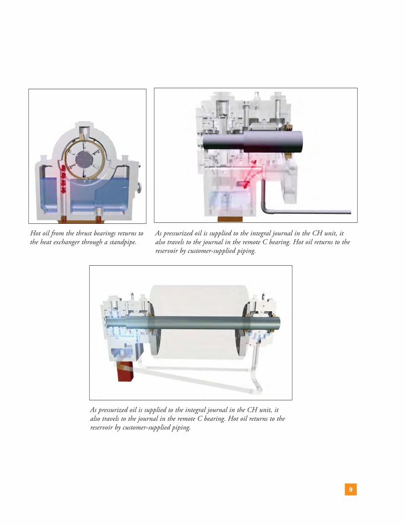
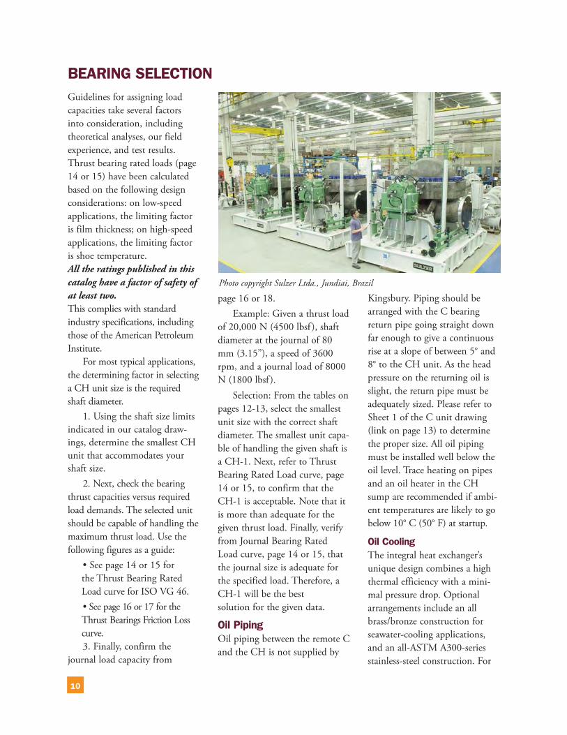
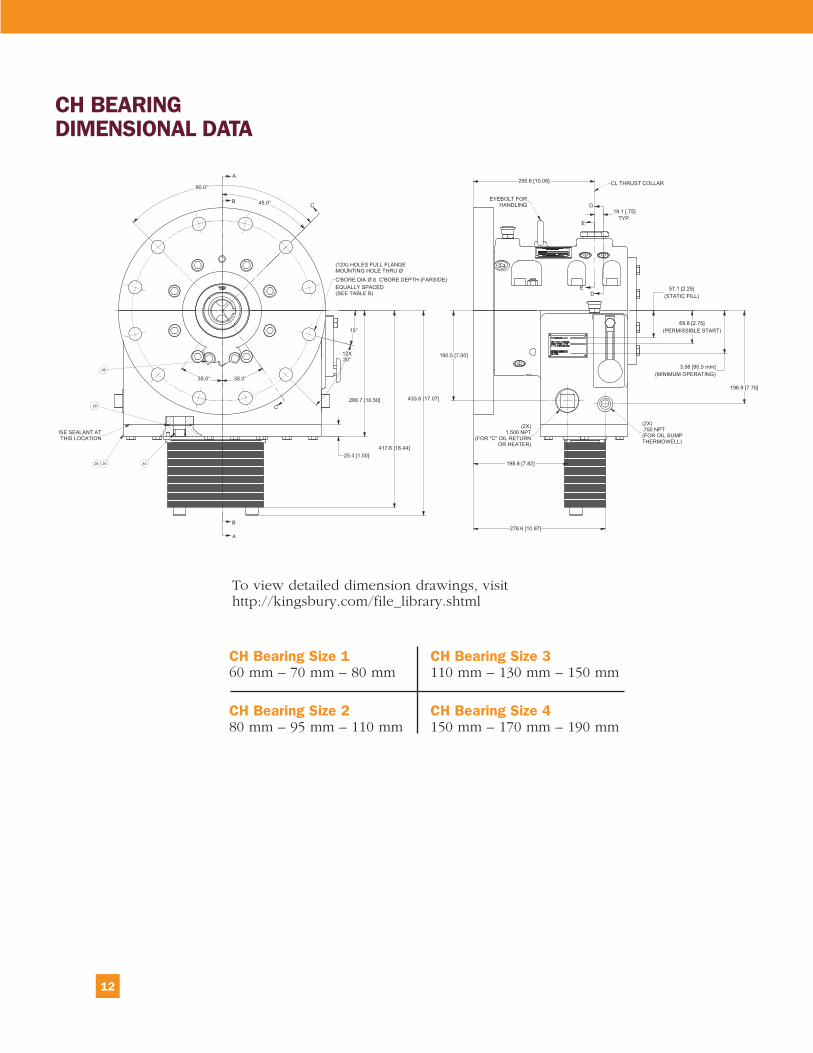
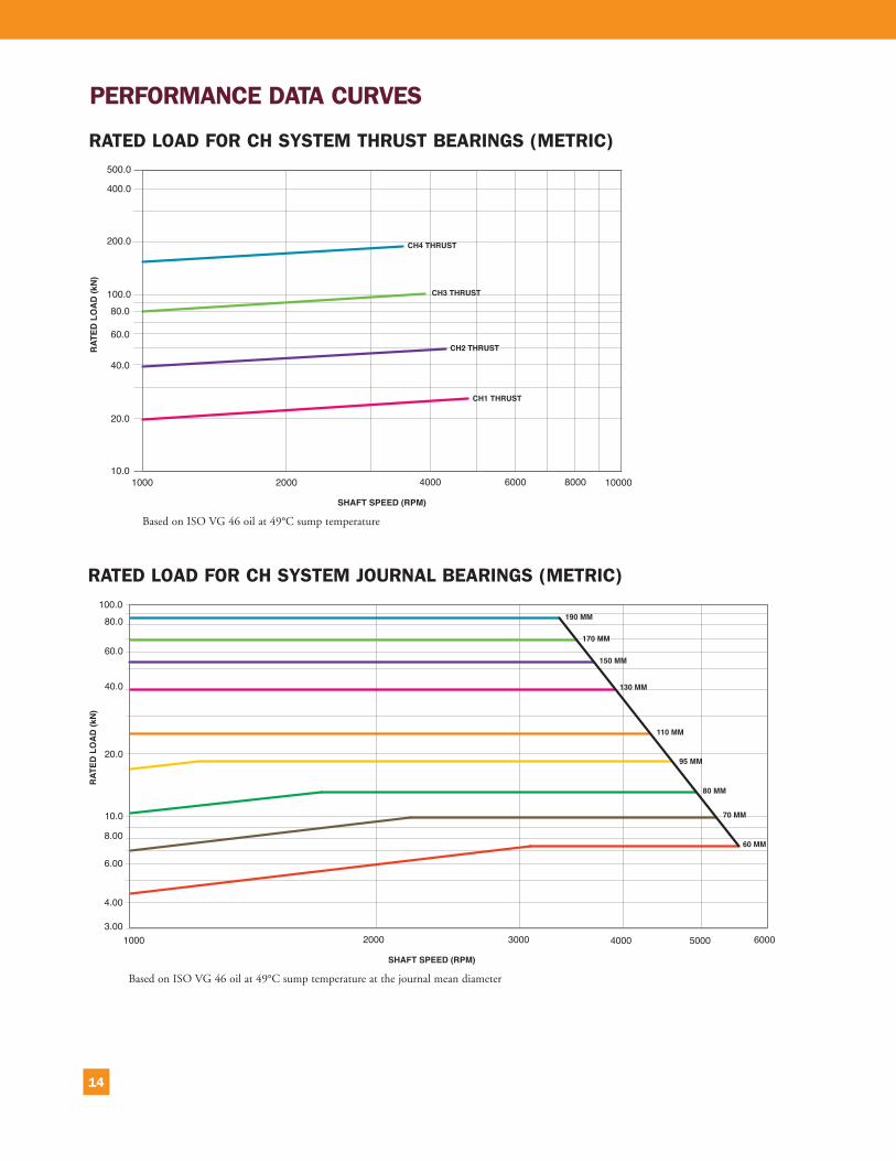
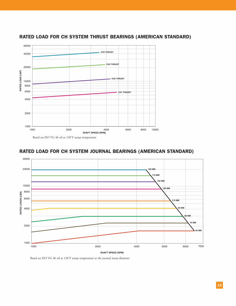

10385 Drummond RoadPhiladelphia PA 19154 USA Telephone +1 215-824-4000Fax +1 215-824-4999wwwkingsburycom