ch super miniature lighted pushbutton switch only …sunmulon.co.jp/english/d_load_e/pdf_e/ch.pdfno...
TRANSCRIPT

NO
NCC
CH Super Miniature Lighted Pushbutton Switch
Only 16mm depth behind panel with built-in resistor.Full-Face, Split-Face, Dual-Color Illumination available.
Amazing bright and even LED illumination.
Switch Connection
SPECIFICATIONS
Contact Electrical Rating Insulation Resistance
Dielectric Strength 600V AC RMS between NC and NO terminal 1500V AC RMS between terminals and ground 50/60Hz for 60sec. at normal ambient temperature and humidity
Contact Resistance
Mechanical Life Alternate Action : more than 200,000 operations Electrical Life Ambient Temperature Ambient Humidity
OPERATING CHARACTERISTICS
Operating Force (max.)
Silver Contact (Gold-Plated) W/E Alloy #1 Cross-bar ContactAC125V,250V 3A(Resistive) AC125V0.1A, DC30V 0.1A(Resistive)
Momentary Action :more than 1,000,000 operations More than 30,000 operations at max. rated load
80% RH (max.)
4.41N Total Travel (max.) 2.5mm
CH
Features Depth behind panel : Only 16mm. LED illumination for Full-Face, Split-Face,Dual-Color. Built-in resistor for 5V,12V,24V use. Light Cartridge is removable from front panel. Button Size: 13.2mm square type,13.2�19.4mm rectangular type. Precision-snap action switch movement with coil spring assures long life and outstanding tactile feedback. Silver Contact (Gold-Plated) and W/E Alloy #1 Cross-bar Contact provided. Accessories: Barriers, Guard Covers, Sockets, etc.
More than 100M� at 500V DC
Less than 50m� (Initial) at DC6V 1A
Less than 50m� (Initial) at DC6V 0.1A
�15�C to �50�C

13.217.8
0.5
2.5
1.4
1620
.5
15.82
22
20.5 16
1.4
2.5
24 17.813.2
15.8
19.4
0.52
*
STRUCTURELIGHT CARTRIDGE
BUTTON (Poly-Carbonate)
FILTER (Used with clear button)
CARTRIDGE BASE (LED mounted)
HOUSING
DIMENSIONS
Sunmulon mark
Sunmulon mark
13.2
mm
Squ
are
But
ton
*3.0 for Dimple Button
Top View
*3.0 for Dimple Button
Top View
LED Full-Face LED Split-Face
Dimple Button
CH
*
13.2
�19
.4m
m R
ect.
But
ton
Tolerance : �0.4mm

LC(+)L1
LC(+)L1
LC(+)
L2L1
LC(+)
L2L1
LC(+)
L2L1
LC(+)
L2L1
BOTTOM VIEW TOP VIEW
BOTTOM VIEW TOP VIEW
LC(+)L1
LC(+)
L2L1
LC(+)
L2L1
BOTTOM VIEW TOP VIEW
LC(+)
L1
LC(+)
L1
L2
LC(+)
L1
L2
LC(+)
L1
L2
LC(+)
L1
LC(+)
L1
COM
NONC
BOTTOM VIEW
BOTTOM VIEW
NCNO
COM COM
NONC NC
NCNO
COM
NCNO
COM
NO
COM
NONCNC
NO L1
5.08 5.08
5.08
5.08
COMCOM
LC(+)
NONCNC
NO L1
L2
2.54
5.08 5.08
5.08
5.08
COM
LC(+)
COM
INTERNAL CONNECTION ARRANGEMENTS
Full-Face
Squa
re
Sunmulon mark
Sunmulon mark
Sunmulon mark
Sunmulon mark
Sunmulon markSunmulon markSunmulon mark
Sunmulon mark
Sunmulon mark Sunmulon mark
Sunmulon mark
Dual-Color Combination
TERMINALSTERMINALS LAYOUT (Square, Rectangular)
SPDT
Full-
Face
TERMINAL SHAPE
SOLDERING TERMINAL
Dual-Color Split-Face
Rec
tang
ular
R
ecta
ngul
ar5V
5V 1
2V 2
4V
12
24V
LED
TERMINALS DIMENSIONS (BOTTOM VIEW)
RedGreen
INDICATOR DPDT
Spli
t-Fac
e Du
al-Co
lorCH
1.6
2 0.5
4.82.
5
0.8
LC(�) �L1 LC(�)�L2
Tolerance : �0.4mm
Tolerance : �0.4mm

LED RATINGS
Square, Full-Face
Max. operating current IFM (mA) DC reverse voltage VR (V)Forward voltage VF (V)
Recommended operating current IF (mA)Wiring diagram
Rect. Dual-Color Rect. Split-Face Rect. Full-Face Square Dual-Color Square, Split-Face
Fig. 2 Fig. 2 Fig. 2 Fig. 1 Fig. 1
R G R G R G
242
655
444
6105
6105
484
242
222
DC Supply Voltage (V)
DC Supply
Square
Voltage (V)
Full-Face
EXTERNAL RESISTORSwitches are normally fitted with internal resistors to operate on 5, 12, 24V DC supply. In case of non-resistor type, suitable external current limiting resistors must be installed as shown by the table and formula:
Current Rating (mA) Split-Face Dual-Color
R GR G Y R GY
LED DATA
CH
208
3.61.5
208
4.25
208
3.63
204
1.81.5
204
2.15
204
1.83
208
3.61.5
208
4.25
408
3.63
408
4.28
408
3.66
20167.21.5
20168.44
20167.23
208
3.61.5
208
4.24
208
3.63
408
3.63
408
4.28
20167.21.5
20168.44
5,12,24V 12,24V5,12,24V 5,12,24V 5V 12,24V 5,12,24V 5VR G Y R G Y R G Y R G Y R G Y
Red=R, Yellow=Y, Green=G
Red=R, Yellow=Y, Green=G
Square 5,12,24(�5%) Rectangular 5(�5%) Rectangular 12,24(�5%)
LED RATINGS (Super CH LED COLOR)
Square, Full-Face, Dual-Color
Max. operating current IFM (mA) DC reverse voltage VR (V)Forward voltage VF (V) IF=5
Forward voltage VF (V) IF=5
Recommended operating current IF (mA)Wiring diagram Fig.1, Dual-Color Fig. 2
5(�5%)12(�5%)24(�5%)5(�5%)
12(�5%)24(�5%)
Full-Face, Dual-Color
EXTERNAL RESISTOR (Super CH LED COLOR)
Current Rating (mA) Split-Face Full-Face
208
4.2 3.63.613
5VR G Y
208
4.2 3.63.610
12V 24V
12V 24V
12V 24V
12V 24V
12V 24V
12V 24V
12V 24V
12V 24V
R G Y
Square, Split-Face
Fig. 2 Fig. 1 Fig. 2
204
2.1 1.81.813
5VR G Y
204
2.1 1.81.8
4.2 3.63.6 8.4 7.27.2 4.2 3.63.6 4.2 3.63.6
10
R G Y
Square Full-Face
405
2.930
5VSB
405
2.921
SW405
3.115
SG20105.815
20106.28
20105.811
SB SG SW205
2.915
205
3.111
205
2.98
5VSB SG SW
205
2.910
205
3.15
205
2.98
SB SG SW
Square Split-Face
Rect.Rect. Full-Face, Dual-Color
Max. operating current IFM (mA) DC reverse voltage VR (V)
Recommended operating current IF (mA)Wiring diagram Fig.1, Dual-Color Fig. 2
408
25
5VR G Y
2016
10
R G Y
Rect. Split-Face
Fig. 2 Fig.1, Dual-Color Fig. 2 Fig. 2
208
13
5VR G Y
208
10
R G Y
Rect. Full-Face
405
2.930
405
3.115
405
2.921
5VSB SG SW
20105.815
20106.2
11
20105.8
8
SB SG SW405
2.915
405
3.115
405
2.921
5VSB SG SW
20105.810
20106.25
20105.88
SB SG SW
Rect. Split-Face
Square 1597
R
2997
15119
G
2999
Y15972997
1087
R
1587
14G
111015119
Y10871587
29149
SB
29149
15SG
851585
SW2513725137
Split-Face
15119
SB
26119
SG
68
51465
SW1210822107
Red=R, Yellow=Y, Green=G
Rectangular
SB=Super Blue, SW=Super White, SG=Super Green
R
VF VF
IF
IFIF
Vcc
Vcc
Vcc
RR Fig. 1
Fig. 2
R =IF
The value of the series resistor can be determined by the formula:
Vcc: Supply Voltage
IF: Forward Current VF: Forward Voltage
* Pulse Lighting :
Vcc�VF Pulse Width PW=100�sec.
Duty Ratio DR=10-1 IFM= 100mA

CH
17.8
17.8
17.8
19
19
23.1
Panel Layout / Panel Cut Dimensions 13.2mm Square
Panel Layout
With
out B
arrie
rs
W
ith B
arrie
rs In
depe
nden
t
Panel Cut Dimensions
Ser
ial
Inde
pend
ent
S
eria
l
17.8n�0.5
16.2�17.8(n�1)�0.2
16.2
�0.
2
Panel thickness: 1.0 � 3.2mm
20.3�18.9(n�1)�0.216
.2�
0.2
Tolerance : �0.4mm
23.1�18.9(n�1)�0.5

22.4�24(n�1)�0.2
24n�0.5
17.8
17.8
29.3�25.1(n�1)�0.5
19
16.2
�0.
2
26.5�25.1(n�1)�0.2
16.2
�0.
2
24
19
29.3
27.2n�1
22.4�27.2(n�1)�0.2
16.2
�0.
2
22.5
22.5
10.5
5
27.2
Panel Layout
With
out B
arrie
rs
W
ith B
arrie
rs
With
Gua
rd C
over
Inde
pend
ent
*Panel Cut Dimension should be after panel paintings. n : number of switches
Panel Cut Dimensions
Panel Layout Panel Cut Dimensions
Panel thickness: 1.0 � 3.2mm
Panel thickness: 1.0 � 2.5mm
Ser
ial
Inde
pend
ent
S
eria
l In
depe
nden
t
Ser
ial
13.2 � 19.4mm Rectangular
Panel Layout / Panel Cut Dimensions
16.2�21(n�1)�0.2
16.2
�0.
2
22.5
21
21n�1
22.5
W
ith G
uard
Cov
er
*Panel Cut Dimension should be after panel paintings. n : number of switches
Panel thickness: 1.0 � 2.5mm
Tolerance : �0.4mm
Inde
pend
ent
S
eria
l
13.2mm Square
CH

CH
VH-0975-KVH-0975-G
VH-0976-KVH-0976-G
CH-2564-KCH-2564-HCH-2565-KCH-2565-H
14.7 4.
4
194.2
14.7 4.
4
194.2
27.2
7
22.5
10.55
11.95
21
7
22.5
10.55
11.95
CH-2479-1CH-2479-2
C C
NO
NC
LC(+)
L1
NO
NC
C
LC(+)
L1
L2NO
NC
C
NO
NC
Sunmulon mark Sunmulon mark
15.6
9.3
4.6
14.3
3.81
17.9
15.6
9.3
4.6
14.3
17.9
5.08 5.08 5.08 5.08
5.08
5.08
5.08
5.08
5.08
3.81
PART NO.
PART NO.
PART NO.
ACCESSORIES
BARRIERSIn case of mounting switches in series, barriers can be used to prevent inadvertentpushing neighbor switch.
GUARD COVER Guard Cover prevents inadvertent and unintentional operations.
13.2mm Square
* The cover to be opened 180 and returned by spring force.
SOCKETFor easy maintenance. (Can be used for both square and rectangular)
Soldering Terminal
Full-Face
Full-Face
Split-Face, Dual-Color
Split-Face Dual-Color
Color Center Barrier Side BarrierBlackGray
BlackSquare
Rect.
GrayBlackGray
13.2 �19.4mm Rectangular
more than 3.0 more than 3.0
mor
e th
an 3
.0
mor
e th
an 3
.0
Tolerance : 0.4mm
Without Barriers
In case of Group Mounting, please leave space as below.
In case of Group Mounting, please leave space as below.
With Barriers
Panel Layout / Panel Cut Dimensions

CH-2687-KCH-2687-H
CH-2688-KCH-2688-H
11.1
17.31.6
5.6
17.3
*
CH-2468CH-2467
1.4 11.2
1.411.2
5.6
1.6
***
CH-2327CH-2326
(17.9n 7.5)
PART NO.
PART NO.
BlackSquare
Square
Square
Rectangular
Rectangular
Gray
BlackRect.Gray
Pane
l Cut
Dim
ensi
ons
MATRIX FITTING FRAME
= number of switch (1-15)
= number of switch (1-10)
n : horizontal number of switch m : vertical number of switch
FILTER DIMENSIONS
* LEGEND FASE
n : horizontal number of switch m : vertical number of switch
ACCESSORIES
(17.9n�7.5)�0.3
17.8
m�
0.3
(24.1n�7.5)�0.3
17.8
m�
0.3
(17.9n�4.4)�0.2
(17.
8m�
0.2)
�0.
2�
0.1
(24.1n�4.4)�0.2
(17.
8m�
0.2)
�0.
2�
0.1
Tolerance : �0.4mm
Panel thickness: 1.0 � 3.2mm Panel thickness: 1.0 � 3.2mm
CH

groove
A
A
A
CH-2325-LRCH-2466-LRCH-2326-LRCH-2327-LRCH-2467-LRCH-2468-LR
CH-2325-LGCH-2466-LGCH-2326-LGCH-2327-LGCH-2467-LGCH-2468-LG
CH-2325-LYCH-2466-LYCH-2326-LYCH-2327-LYCH-2467-LYCH-2468-LY
CH-2325-LMCH-2466-LMCH-2326-LMCH-2327-LMCH-2467-LMCH-2468-LM
CH-2325-CCCH-2466-CC
CH-2524-CCCH-2525-CC
REPLACEMENT PARTS
BUTTON/FILTER Red
Square Button
Square Split-Face Filter
Rect. Split-Face Filter
DimpleClear Milk-White Yellow Green
Rect. Full-Face Filter
Square Full-Face Filter Rect. Button
Push up metal plate A with -screw driver, and pull out socket.
6. Removing Socket Insert Switch into Socket with right direction (Both Sunmulon Mark should be same side) and push in until stop.
5. Fitting Socket Insert Light Cartridge into Housing with right direction and push in until click.
4. Fitting Light Cartridge
Set Filter(s) as shown onto cartridge carefully, then put button on and push until click.
3. Fitting Filter(s) Hook fingernails at A and gently release the clip, and release another side as well.
2. Removing Button Hang the cartridge with hooking fingernails in the groove, and pull out.
1. Removing Light Cartridge
ASSEMBLY & DISASSEMBLY
CH

HOUSING COLOR
CH 1 2 1 2
S
123456
KH
789
S0W0S2W2S3W3K0K2K3N0N2N3
MAL
03456
ORDERING CODE I
OPERATIONMomentary
Square Full-FaceRect. Full-FaceSquare Split-FaceRect. Split-FaceSquare Dual-ColorRect. Dual-ColorDimple B. Square Full-FaceDimple B. Square Split-FaceDimple B. Square Dual-ColorDimple B. Rect Full-FaceDimple B. Split-FaceDimple B. Dual-Color
IndicatorAlternate
CONTACT Indicator SPDT Silver (Gold-Plated) DPDT Silver (Gold-Plated)SPDT W/E Alloy #1CrossbarDPDT W/E Alloy #1Crossbar
BUTTON SHAPE / ILLUMINATION TYPE
LED COLOR Full-Face : Put color no. into the frame 1Split-Face : Put color no. into the frame 1,2
Dual-Color Put color no. 78 into the frame 1,2 (available 78 only)
Without LED
BUTTON COLOR
Red
FILTER COLOR
TERMINAL#110 Tab/Solder
C PCBK With ConnectorN Without Connector
YellowGreen
BlackGray
Supply Voltage to LED5V Built-in Resistor 12V Built-in Resistor24V Built-in Resistor5V Non-Resistor 12V Non-Resistor24V Non-ResistorWithout LED
Sunmulon
12
Sunmulon
12
NOTES1) In case of Split-Face, LED and Filter color location should be specified as follow:
3) In case of Split-Face, button color should be C (clear).4) In case of Dual-Color, button should be C (clear) with Milk-White filter or Milk-White button.5) In case of simultaneous illumination for Split-Face and Dual-Color with 24V,use 6. Non Resistor type and apply external resistor accordingly.
6) Dimple Button type is only clear color. Therefore, button color should be C (clear). 7) Please be noted that the color of "Yellow" for LED Button
8) If you purchase a wire harness separately, please specify N (without connector).
Filter is actually "Orange Yellow" not Lemon Yellow.
2) In case of Split-Face and Dual-Color, simultaneous illumination is not possible for 24V built-in resistor type, cause of heat, please select non resistor type and apply required external resistor.
�
RGYMB
Red
BlueMilk-White
C Clear
YellowGreen
1234
Red
Milk-White YellowGreen
*Generally, in case of using color button, filters are not necessary.
Without Filter* �
�
6 Blue
Super CH LED COLOR708090141618
Dual-Color7080,8090,9070only
Split-Face70,80,90 combination or14,16,18 combination
Red
Super Blue YellowGreen
Super GreenSuper White
Full-Face : Put color no. into the frame 1
Split-Face : Put color no. into the frame 1,2
CH
10
CH 1 2 1 2
S0W0S2W2S3W3K0K2K3N0N2N3
CH
MAL
03456
S
KH
S0W0S2W2
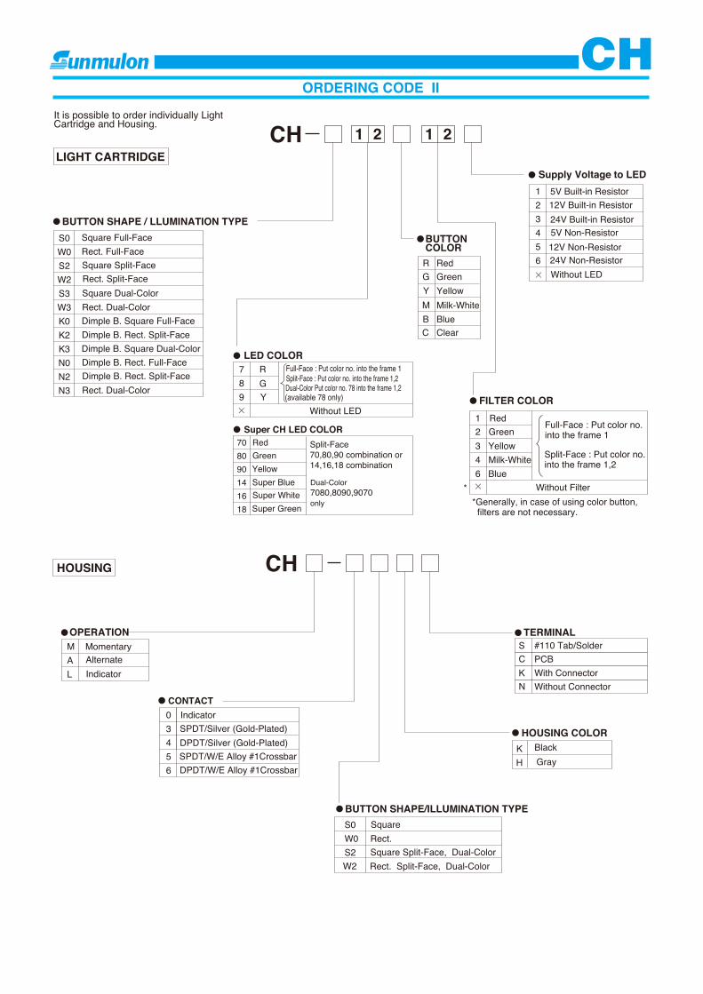
It is possible to order individually Light Cartridge and Housing.
LIGHT CARTRIDGE
HOUSING
Square Rect.Square Split-Face, Dual-ColorRect. Split-Face, Dual-Color
ORDERING CODE II
Square Full-FaceRect. Full-FaceSquare Split-FaceRect. Split-FaceSquare Dual-ColorRect. Dual-Color
Rect. Dual-Color
Dimple B. Square Full-FaceDimple B. Rect. Split-FaceDimple B. Square Dual-ColorDimple B. Rect. Full-FaceDimple B. Rect. Split-Face
OPERATIONMomentary
IndicatorAlternate
CONTACT Indicator SPDT/Silver (Gold-Plated) DPDT/Silver (Gold-Plated)SPDT/W/E Alloy #1CrossbarDPDT/W/E Alloy #1Crossbar
BUTTON SHAPE/ILLUMINATION TYPE
BUTTON SHAPE / LLUMINATION TYPE
HOUSING COLOR
TERMINAL#110 Tab/Solder
C PCBK With ConnectorN Without Connector
RGYMB
BUTTON COLOR
Red
BlueMilk-White
C Clear
YellowGreen
BlackGray
789
LED COLOR Full-Face : Put color no. into the frame 1Split-Face : Put color no. into the frame 1,2
Dual-Color Put color no. 78 into the frame 1,2 (available 78 only)
Without LED
R
YG
FILTER COLOR1234
Red
Milk-White YellowGreen
Full-Face : Put color no. into the frame 1
Split-Face : Put color no. into the frame 1,2
*Generally, in case of using color button, filters are not necessary.
Without Filter*
Supply Voltage to LED123456
5V Built-in Resistor 12V Built-in Resistor24V Built-in Resistor5V Non-Resistor 12V Non-Resistor24V Non-ResistorWithout LED
�
�
6 Blue
�
Super CH LED COLOR708090141618
Dual-Color7080,8090,9070only
Split-Face70,80,90 combination or14,16,18 combination
Red
Super Blue YellowGreen
Super GreenSuper White
CH

12
TERMINAL LAYOUT
13.2
mm
Squ
are
Butto
n13
.2�
19.4
mm
Rec
t. Bu
tton
Sunmulon mark
SPECIFICATIONS
Without soldering, mounting and maintenance is a connector type available.
Pin No. Terminal123456
COMNCNOLC
Reduced wiring
There are dedicated connectors for SPDT and Indicator and for DPDT. Wire harness is also dedicated to each contact.Please refer to ACCESSORIES for details.
Connector Type
CH
DIMENSIONS
ContactElectrical RatingInsulation Resistance
Dielectric Strength
Silver Contact (Gold-Plated)AC100V 1A, DC30V 1A (Resistive)
W/E Alloy #1 Cross-bar ContactAC100V 0.1A, DC30V 0.1A (Resistive)
Contact Resistance
Mechanical Life Momentary Action : more than 1,000,000 operations Alternate Action : more than 200,000 operationsElectrical Life More than 30,000 operations at max. rated loadAmbient Temperature �15�C to�50�CAmbient Humidity 80% RH (max.)
More than 100M at 500V DC600V AC RMS between NC and NO terminal1500V AC RMS between terminals and ground50/60Hz for 60sec. at normal ambient temperature and humidity
Less than 50m (Initial)at DC6V 1A
Less than 50m (Initial)at DC6V 0.1A
Dimple Button type : 3.0
Dimple Button type : 3.0
Connetcor(JST made B 6B-PH-K-S)
ACCESSORIES
Connector
Wire Harness
A length Part NoEH-3250-1100cm
200cm EH-3250-21Pin no.
Wire Color Brown2 3 4 5 6
Red Orange Yellow Green Blue
Housing(JST made PHR-6)
Contact Pin(JST made SPH-002T-P0.5S)
Applicable wire : AWG#30 #24
Wire : UL1061, AWG26 equivalent
Part No EH-3251 Connector (1Housing & 6 Contact Pins)to be appended.
A
16
13.217.8
2.5
1.4
17
(23)
15.8
Sunmulon mark
Sunmulon mark
TOP VIEW
22
(23)
171.
42.
5
24 17.8
13.2
15.8
19.4
TOP VIEW
●SPDT, Indicator
●SPDT, Indicator
●SPDT, Indicator3
2123456

13
TERMINAL LAYOUT
13.2
mm
Squ
are
Butto
n13
.2�
19.4
mm
Rec
t. Bu
tton
Sunmulon mark
Pin No. Terminal
CHDIMENSIONS
Dimple Button type : 3.0
Dimple Button type : 3.0
ACCESSORIES
A length Part NoEH-5177-1100cm
200cm EH-5177-2
Connector
Wire HarnessWire : UL1061, AWG26 equivalent
Part No EH-5180
1Pin no.Wire Color Brown
2 3 4 5 6 7 8 9Red Orange Yellow Green Blue Purple Gray White
Sunmulon mark
Sunmulon mark
TOP VIEW
TOP VIEW
●DPDT
●DPDT
●DPDTConnector (1 Housing & 9 contact Pins) to be appended.
19
(JST made GHR-09V-S)Housing
(JST made SSHL-002T-P02)Contact Pin
Applicable wire : AWG#30~#26ConnetcorJST madeBM09B-GHS-TBT
A
(1.65)
123456
987
COM1
COM2
NC1
NC2
L2L1
NO1
NO2
LC
(BOTTOM VIEW)
19
□13.2□17.8
2.5
1.4
18.8
(23)
※
□15.8
2.5
24 17.813.219.4※
(23) 18.8
1.4
22 15.8