ch t 8chapter 8. system modelselearning.kocw.net/contents4/document/lec/2013/konku… · ·...
TRANSCRIPT

Ch t 8Chapter 8.
System Models

ObjectivesObjectives
T l i h th t t f t h ld b d ll d t f• To explain why the context of a system should be modelled as a part of requirements engineering process
• To describe behavioural modelling, data modelling and object modellingT h h CASE kb h t t d lli• To show how CASE workbenches support system modelling
138Konkuk University

System ModellingSystem Modelling
H l l t t d t d th f ti lit f th t• Helps analysts to understand the functionality of the system. – System models are used to communicate with customers.
Diff t d l t th t f diff t ti• Different models present the system from different perspectives– External perspective : showing the system’s context or environment– Behavioural perspective : showing the behaviour of the system
Structural perspective : showing the system or data architecture– Structural perspective : showing the system or data architecture
• System model typesData processing model: showing how the data is processed at different stages– Data processing model: showing how the data is processed at different stages
– Composition model: showing how entities are composed of other entities– Architectural model: showing principal sub-systems– Classification model: showing how entities have common characteristicsClassification model: showing how entities have common characteristics– Stimulus/response model: showing the system’s reaction to events– Many ones
139Konkuk University

System Context ModelSystem Context Model
S C ( d l ) d ill h i l f• System Context (models) are used to illustrate the operational context of a system
– Showing what lies outside the system boundaries– Showing the system and its relationship with other systems– Social and organizational concerns may affect the decision of system
boundaries.
System Context Model f
SecuritySystem
B hfor ATM
Auto-TellerSystem
AccountDatabase
Branch Accounting
System
System
MaintenanceSystem
UsageDatabase
Branch Counter System
140Konkuk University
System

Process ModelProcess Model
P d l h h ll d b h• Process models show the overall process supported by the system.
Equipment Spec
Checked Spec
DeliveryNote
DeliveryN t
Specify equipment required
Validate specification
Get cost estimate
Accept delivery of equipment
Check delivery items
Spec. Spec.
Equipment Spec. +S li
Order
Note
Installation
Supplier Database
Find supplier
Supplier list
Choose Supplier
Place equipment
order
Install equipment
q pSpec. Supplier +
estimate
Order Notification
InstallationInstructions
Equipment procurement process
order
Accept delivered
InstallationAcceptance
Order Detailsand
Blank Order Form Checked and
Signed Order Form
Equipment procurement process delivered equipment
i
EquipmentDetails
141Konkuk University
Equipment Database

Behavioural ModelBehavioural Model
B h i l d l d t d ib th ll b h i f th• Behavioural models are used to describe the overall behaviour of the system.
– Data processing models : showing how data is processed as it moves through the systemthe system
– State machine models : showing how the system responses to events
– Two models show different perspectives.p p– Both of them are required to describe the system’s behaviour.
142Konkuk University
Data Processing ModelData Processing Model
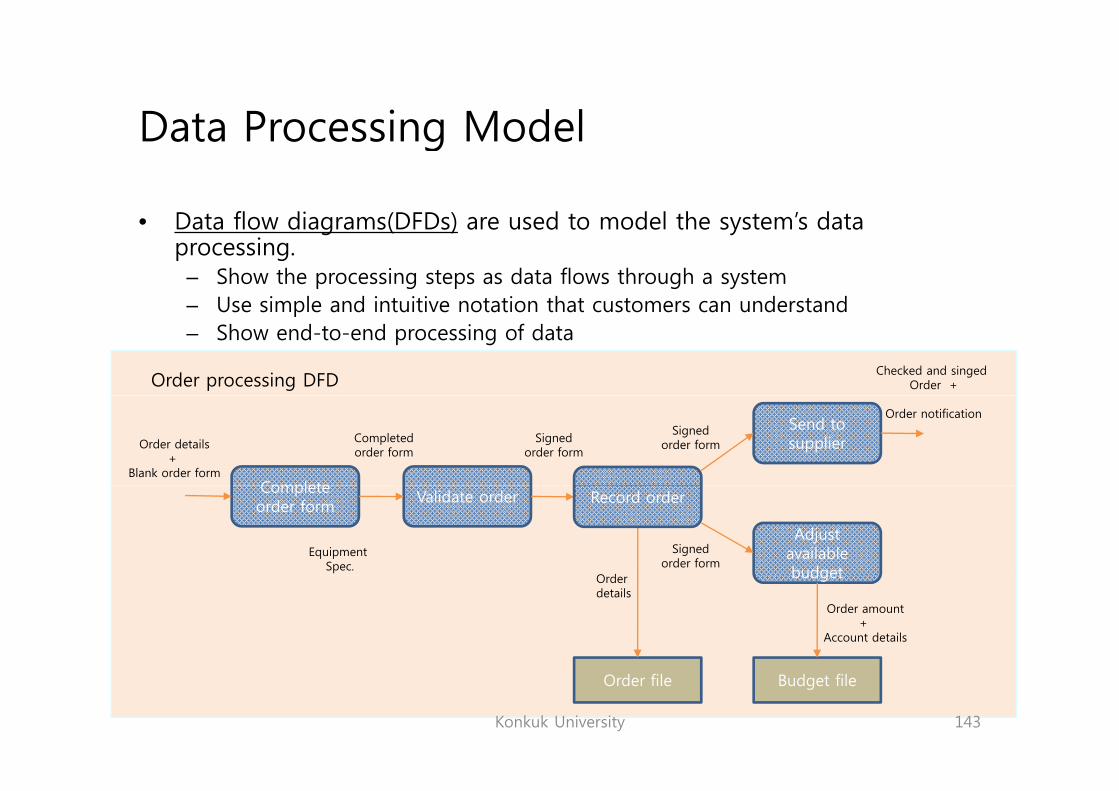
D t fl di (DFD ) d t d l th t ’ d t• Data flow diagrams(DFDs) are used to model the system’s data processing.
– Show the processing steps as data flows through a system– Use simple and intuitive notation that customers can understand– Use simple and intuitive notation that customers can understand– Show end-to-end processing of data
Order processing DFDChecked and singed
Order +
Complete
Send to supplierCompleted
order formSigned
order formOrder details
+ Blank order form
Signedorder form
Order notification
Complete order form
Validate order
O d
Equipment Spec.
Record order
Adjust available budget
Signedorder form
Orderdetails
budget
Order amount+
Account details
143Konkuk University
Order file Budget file
State Machine ModelState Machine Model
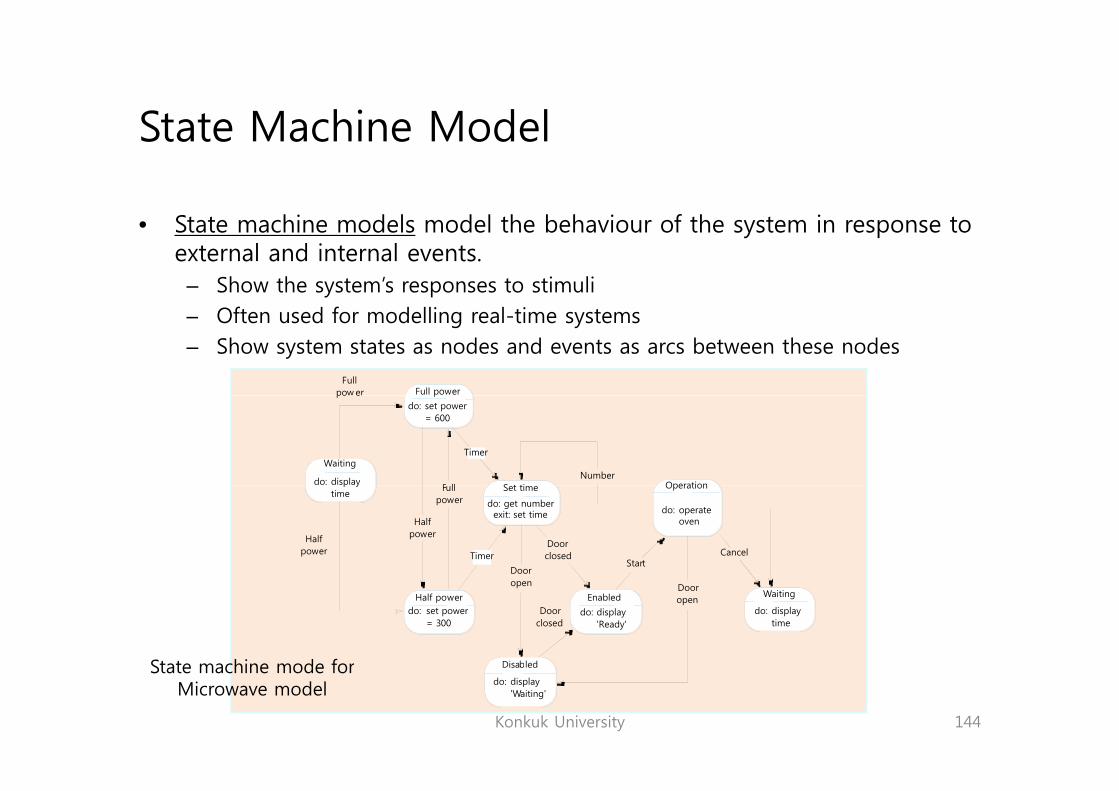
S hi d l d l h b h i f h i• State machine models model the behaviour of the system in response to external and internal events.
– Show the system’s responses to stimuli– Often used for modelling real-time systems– Show system states as nodes and events as arcs between these nodes
Full powerFull
pow er ppo e
F llNumber
do: set power= 600
S t ti Operation
Waiting
do: display
Timer
do: operateoven
Halfpower
Halfpower
Fullpower
Door
Doorclosed
Start
Set time
do: get numberexit: set time
Operation
Cancel
p ytime
Timer
State machine mode for
Enabled
open
Doorclosed
DooropenHalf power
do: set power= 300
Disabled
Waiting
do: displaytime
do: display'Ready'
Konkuk University 144
State machine mode forMicrowave model
Disabled
do: display'Waiting'

Semantic Data ModelSemantic Data Model
S i d d l d d ib h l i l f d• Semantic data models are used to describe the logical structure of data processed by the system.
– Entity-relation-attribute model : setting out the entities in the system, l ti hi b t th titi d th tit tt ib trelationships between these entities, and the entity attributes
– Widely used in rational database design
SourceArticle
Library semantic model
Sourcetitlepublisherissuedatepages
1
Articletitleauthorspdf filefee
fee-payable-to
published-inm n
1
11
h li k
1
n
delivers in
1
1
CopyrightAgencyname
Country
copyright formtax rate
1
Orderorder numbertotal payment
in
has-links
Buyer
places1
n
address tax ratetotal paymentdatetax status
145Konkuk University
Buyer
nameaddresse-mailbilling info

Object ModelObject Model
Obj d l d ib h i f bj l d h i• Object models describe the system in terms of object classes and their associations.
– An object class is an abstraction over a set of objects with common attributes d th i ( ti )and the services (operations).
– Object classes are reusable across systems.
• Various object models– Inheritance model– Aggregation model– Interaction model
146Konkuk University
Inheritance ModelInheritance Model
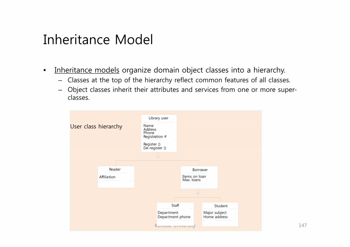
I h i d l i d i bj l i hi h• Inheritance models organize domain object classes into a hierarchy.– Classes at the top of the hierarchy reflect common features of all classes.– Object classes inherit their attributes and services from one or more super-
lclasses.
Library user
User class hierarchy NameAddressPhoneRegistration #
Register ()De-register ()
Affiliation
Reader
Items on loanMax loans
Borrower
Max. loans
Staff Student
147Konkuk University
DepartmentDepartment phone
Major subjectHome address

Multiple InheritanceMultiple Inheritance
M l i l i h i ll bj l i h i f l• Multiple inheritance allows object classes to inherit from several super-classes.
– May lead to semantic conflicts where attributes/services with the same name i diff t l h diff t tiin different super-classes have different semantics
– Make class hierarchy reorganisation more complex
AuthorEditionPublication date
Book
SpeakerDurationRecording date
Voice recording
Publication dateISBN
Recording date
# Tape
Talking book
148Konkuk University
p

Object Aggregation ModelObject Aggregation Model
A i d l h h l d f h l• Aggregation models show how classes are composed of other classes.– Similar to the part-of relationship in semantic data models
Course titleNumberYearInstructor
Study pack
Instructor
Videotape
Tape ids.
Lecturenotes
Text
OHP slides
Slides
Assignment
Credits
Solutions
Text
Exercises
#Problems
149Konkuk University
DiagramsDescription
Object Behaviour ModelObject Behaviour Model
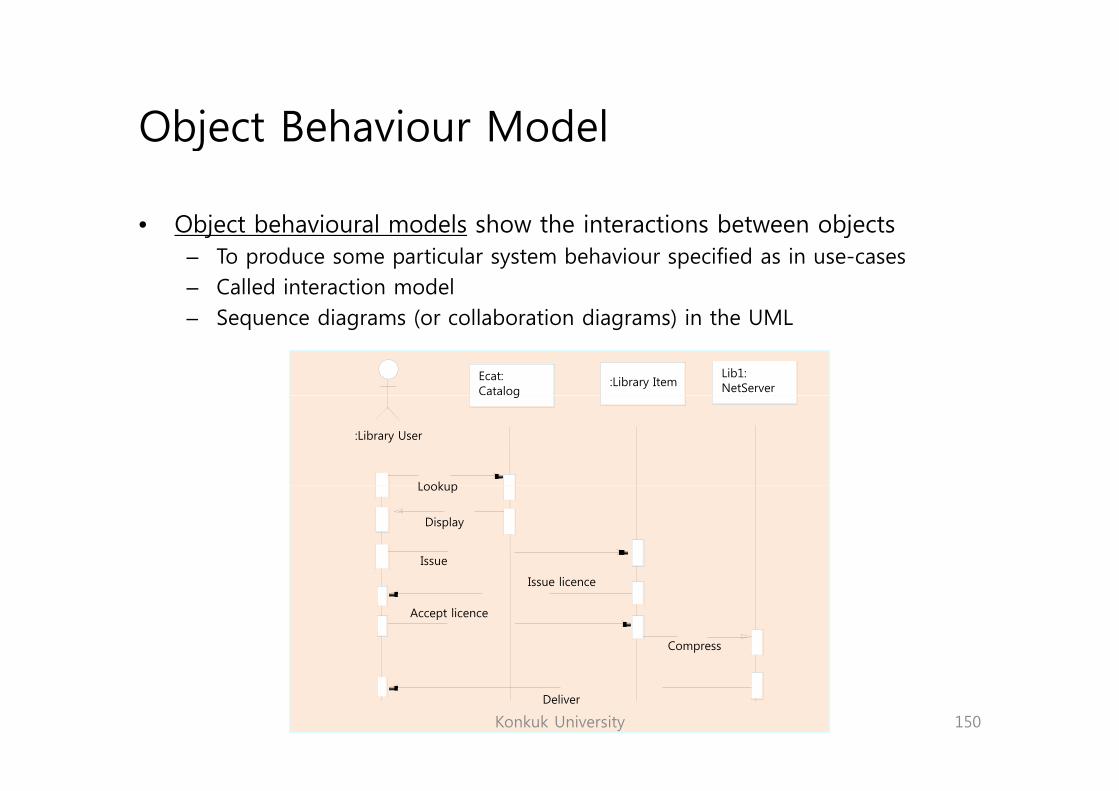
Obj b h i l d l h h i i b bj• Object behavioural models show the interactions between objects – To produce some particular system behaviour specified as in use-cases– Called interaction model– Sequence diagrams (or collaboration diagrams) in the UML
Ecat:Catalog
:Library ItemLib1:NetServer
:Library User
g
LookupLookup
Issue
Display
Issue licence
Accept licence
Compress
150Konkuk University
Deliver

Structured MethodStructured Method
S d h d i d lli i h f• Structured methods incorporate system modelling as an inherent part of the method.
• Structured methods define – a set of models– a process for deriving these modelsp g– rules and guidelines that should apply to the models– CASE tools to support system modelling
• CASE Workbench:– A coherent set of tools that is designed to support related software process activities
such as analysis, design or testing.A l i d d i kb h d lli d i b h i– Analysis and design workbenches support system modelling during both requirements engineering and system design.
– May support a specific design method– May support to create several different types of system model
151Konkuk University

Analysis and Design Workbench: An exampleAnalysis and Design Workbench: An example
Data Dictionary
Structural Diagramming
T l
Report Generation F ili iDictionary Tools Facilities
Code Generator
Query Language Facilities
Central Information Repository ac t esp y
Form Creation
Tools
Design, Analysis and Checking
tools
Import/Export Facilities
152Konkuk University
SummarySummary
A d l i b t t t i C l t t f d l• A model is an abstract system view. Complementary types of model provide different system information.
• Context models show the position of a system in its environment with other systems and processesother systems and processes.
• Data flow models are used to model the data processing in a system.• State machine models model the system’s behaviour in response to
internal or external eventsinternal or external events.• Semantic data models describe the logical structure of data which is
imported to or exported by the systems.• Object models describe logical system entities their classification and• Object models describe logical system entities, their classification and
aggregation.• Sequence models show the interactions between actors and the system
objects that they use.j y• Structured methods provide a framework for developing system models.
153Konkuk University

Konkuk University 154