ch14
TRANSCRIPT

Chapter 14Special Purpose
Op-Amp Circuits

Objectives
Analyze the operation of instrumentation amplifier Analyze the operation of an isolation amplifier
Analyze the operation of log and antilog amplifiers
Analyze the operation of operational transconductance amplifier (OTA)
Analyze the operation of log and antilog amplifiers Analyze the operation of other special types of op-amp circuits
Introduction
The op-amp circuits described in this chapter are variations of basic op-amp circuits. They are designed to handle different types of environments and special applications. Rejection of noise, isolation, and voltage-to-current amplification are just a few special applications.

Instrumentation AmplifiersThe key characteristics of an instrumentation amplifier are high input impedance, high common-mode rejection, low output offset, low output impedance. This type of amp circuit is designed to reject common-mode noise associated with data acquisition.

Instrumentation AmplifiersGain for the instrumentation amplifier is set by an external gain resistor (RG). Signals applied to the inputs are combined with any common-mode signals effectively cancelled out. The output would be only the wanted signal. The gain can be determined by the formula below.
Acl = 1 + 2R/RG
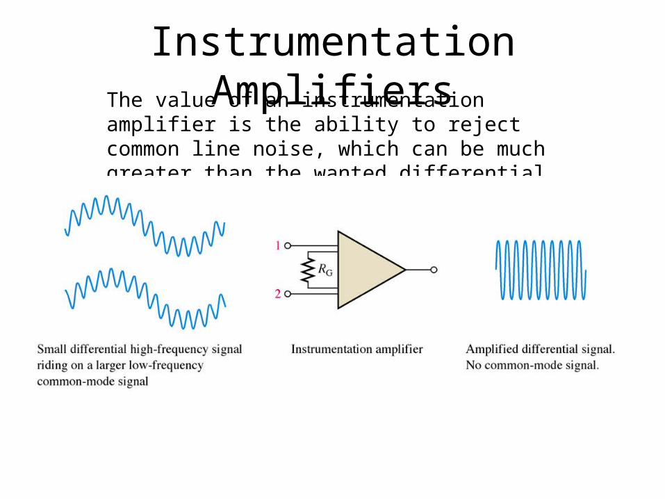
Instrumentation AmplifiersThe value of an instrumentation amplifier is the ability to reject common line noise, which can be much greater than the wanted differential signal.

Figure 14–4 The AD622 instrumentation amplifier.
Thomas L. Floyd Electronic Devices, 7e
Copyright ©2005 by Pearson Education, Inc.Upper Saddle River, New Jersey 07458
All rights reserved.

Figure 14–5 The AD622 with a gain-setting resistor.
Thomas L. Floyd Electronic Devices, 7e
Copyright ©2005 by Pearson Education, Inc.Upper Saddle River, New Jersey 07458
All rights reserved.
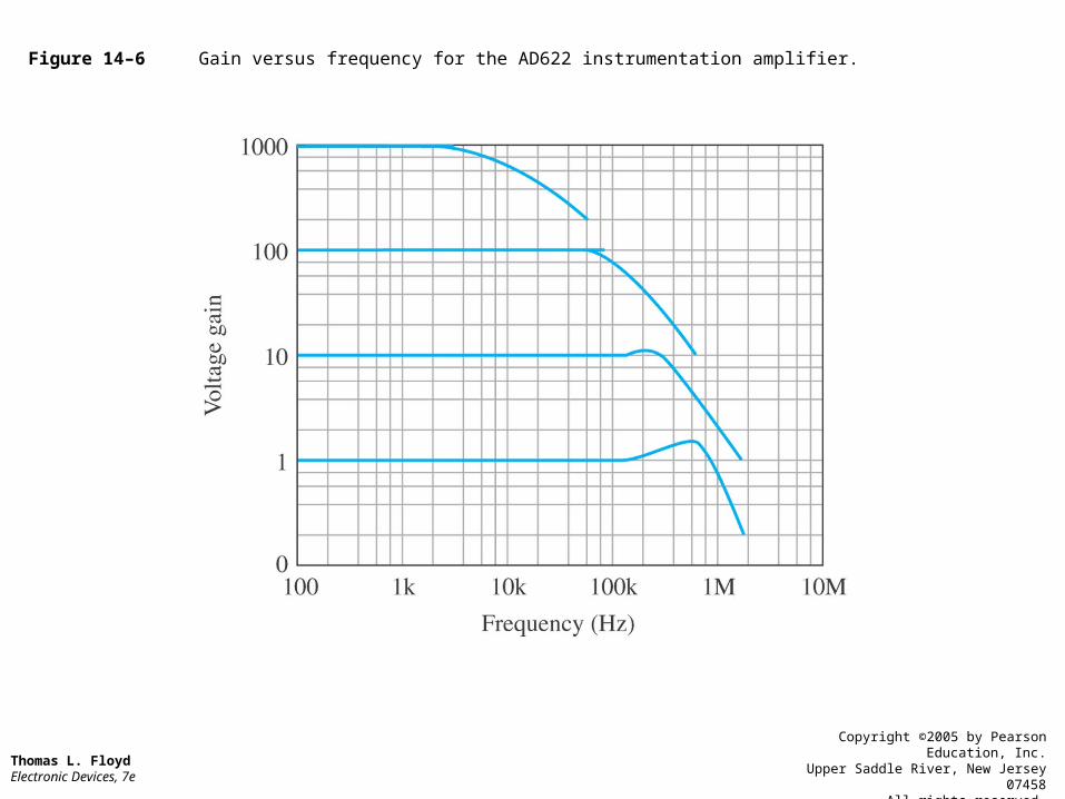
Figure 14–6 Gain versus frequency for the AD622 instrumentation amplifier.
Thomas L. Floyd Electronic Devices, 7e
Copyright ©2005 by Pearson Education, Inc.Upper Saddle River, New Jersey 07458
All rights reserved.
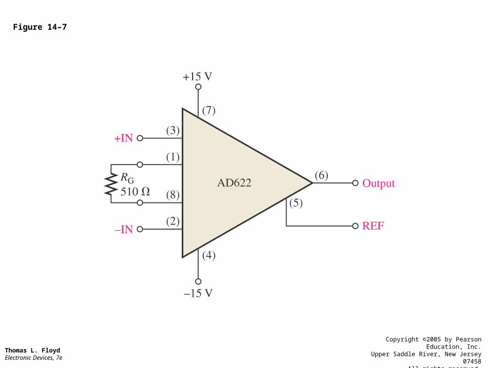
Figure 14–7
Thomas L. Floyd Electronic Devices, 7e
Copyright ©2005 by Pearson Education, Inc.Upper Saddle River, New Jersey 07458
All rights reserved.

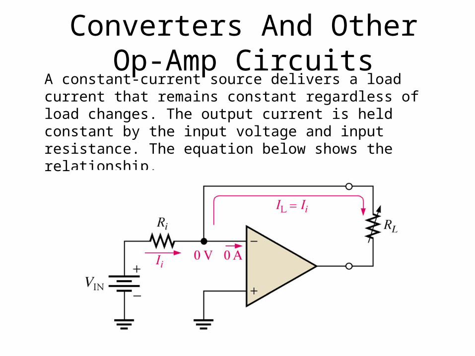
Converters And Other Op-Amp Circuits
A constant-current source delivers a load current that remains constant regardless of load changes. The output current is held constant by the input voltage and input resistance. The equation below shows the relationship.
IL = VIN/Ri

Figure 14–34 Current-to-voltage converter.
Thomas L. Floyd Electronic Devices, 7e
Copyright ©2005 by Pearson Education, Inc.Upper Saddle River, New Jersey 07458
All rights reserved.

Converters And Other Op-Amp Circuits
The current-to-voltage converter produces an output voltage based on the input current. The formula below shows the relationship.
Vout = IiRf

Converters And Other Op-Amp Circuits
The peak detector charges to the peak level of the input and holds that charge in the capacitor until greater peak occurs. The diode prevents the capacitor from discharging.
Summary The basic instrumentation amplifier is formed by three op-amps and seven resistors, including the gain-setting resistor RG.
The value of the instrumentation amp is the high common-mode rejection.
The isolation op-amp is used to electrically isolate the input from the output.
The OTA is a voltage to current amplifier.
The OTA’s gain can be varied by the IBIAS input.
The log and antilog amps produce logarithmic output based on the signal input and inverse logarithmic output based on the signal input respectively.