ch2problems2
TRANSCRIPT

8/2/2019 Ch2Problems2
http://slidepdf.com/reader/full/ch2problems2 1/35
Sequential Circuits Problems(I)
Prof. Sin-Min Lee
Department of Mathematics andComputer Science
Algorithm = Logic + Control

8/2/2019 Ch2Problems2
http://slidepdf.com/reader/full/ch2problems2 2/35

8/2/2019 Ch2Problems2
http://slidepdf.com/reader/full/ch2problems2 3/35

8/2/2019 Ch2Problems2
http://slidepdf.com/reader/full/ch2problems2 4/35

8/2/2019 Ch2Problems2
http://slidepdf.com/reader/full/ch2problems2 5/35

8/2/2019 Ch2Problems2
http://slidepdf.com/reader/full/ch2problems2 6/35

8/2/2019 Ch2Problems2
http://slidepdf.com/reader/full/ch2problems2 7/35
8/2/2019 Ch2Problems2
http://slidepdf.com/reader/full/ch2problems2 8/35

8/2/2019 Ch2Problems2
http://slidepdf.com/reader/full/ch2problems2 9/35

8/2/2019 Ch2Problems2
http://slidepdf.com/reader/full/ch2problems2 10/35
8/2/2019 Ch2Problems2
http://slidepdf.com/reader/full/ch2problems2 11/35
8/2/2019 Ch2Problems2
http://slidepdf.com/reader/full/ch2problems2 12/35

8/2/2019 Ch2Problems2
http://slidepdf.com/reader/full/ch2problems2 13/35

8/2/2019 Ch2Problems2
http://slidepdf.com/reader/full/ch2problems2 14/35
8/2/2019 Ch2Problems2
http://slidepdf.com/reader/full/ch2problems2 15/35

8/2/2019 Ch2Problems2
http://slidepdf.com/reader/full/ch2problems2 16/35
We wish to design a synchronous sequential circuitwhose state diagram is shown in Figure. The type of
flip-flop to be use is J-K Two flip-flops are needed torepresent the four states andare designated Q0Q1. The
input variable is labelled x.

8/2/2019 Ch2Problems2
http://slidepdf.com/reader/full/ch2problems2 17/35
. Excitation table for JK flip-flop
Excitation table of the circuit

8/2/2019 Ch2Problems2
http://slidepdf.com/reader/full/ch2problems2 18/35
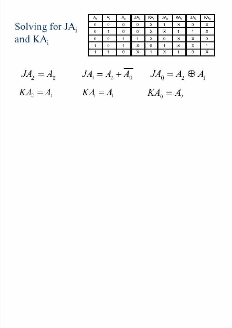
The simplified Boolean functions for thecombinational circuit can now be derived

8/2/2019 Ch2Problems2
http://slidepdf.com/reader/full/ch2problems2 19/35

8/2/2019 Ch2Problems2
http://slidepdf.com/reader/full/ch2problems2 20/35

8/2/2019 Ch2Problems2
http://slidepdf.com/reader/full/ch2problems2 21/35

8/2/2019 Ch2Problems2
http://slidepdf.com/reader/full/ch2problems2 22/35
8/2/2019 Ch2Problems2
http://slidepdf.com/reader/full/ch2problems2 23/35
8/2/2019 Ch2Problems2
http://slidepdf.com/reader/full/ch2problems2 24/35
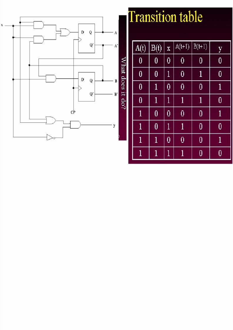
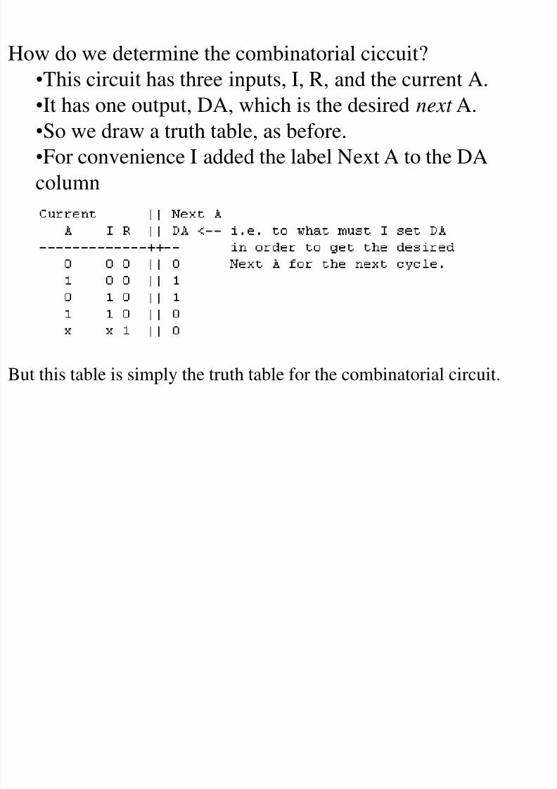
How do we determine the combinatorial ciccuit?
•This circuit has three inputs, I, R, and the current A.
•It has one output, DA, which is the desired next A.•So we draw a truth table, as before.
•For convenience I added the label Next A to the DA
column
But this table is simply the truth table for the combinatorial circuit.

8/2/2019 Ch2Problems2
http://slidepdf.com/reader/full/ch2problems2 25/35

8/2/2019 Ch2Problems2
http://slidepdf.com/reader/full/ch2problems2 26/35
8/2/2019 Ch2Problems2
http://slidepdf.com/reader/full/ch2problems2 27/35
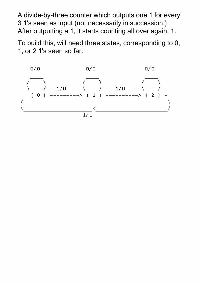
A divide-by-three counter which outputs one 1 for every
3 1's seen as input (not necessarily in succession.)
After outputting a 1, it starts counting all over again. 1.
To build this, will need three states, corresponding to 0,
1, or 2 1's seen so far.

8/2/2019 Ch2Problems2
http://slidepdf.com/reader/full/ch2problems2 28/35

8/2/2019 Ch2Problems2
http://slidepdf.com/reader/full/ch2problems2 29/35
Designing with JK Flip-Flops
• The design of a sequential circuit with other thanthe D type is complicated by the fact that the flip-flop input equations for the circuit must be derived
indirectly from the state table. When D-type flip-flops are employed, the input equations areobtained directly from the next state. This is notthe case for JK and other types of flip-flops. In
order to determine the input equations for theseflip-flops, it is necessary to derive a functionalrelationship between the state table and the inputequations.

8/2/2019 Ch2Problems2
http://slidepdf.com/reader/full/ch2problems2 30/35
Flip-Flop Excitation Tables
• A table that lists the required inputs for a given
change of state is known as an excitation table.
Example of an excitation table is shown below:

8/2/2019 Ch2Problems2
http://slidepdf.com/reader/full/ch2problems2 31/35
Flip-Flop Excitation Tables (cont)
The excitation table show four differenttypes of flip-flops. Each table has a column
for the present state Q(t), a column for thenext state Q(t + 1), and a column for eachflip-flop input to show how the requiredtransition is achieved. The symbol X in the
table represents a don’t-care condition,which means that it does not matter whetherthe input is 0 or 1.

8/2/2019 Ch2Problems2
http://slidepdf.com/reader/full/ch2problems2 32/35
Flip-Flop Excitation Tables (cont)
The excitation table for the D flip-flop shows
that the next state is always equal to the D
input and is independent of the presentstate. This can be represented algebraically:
D = Q(t + 1)

8/2/2019 Ch2Problems2
http://slidepdf.com/reader/full/ch2problems2 33/35
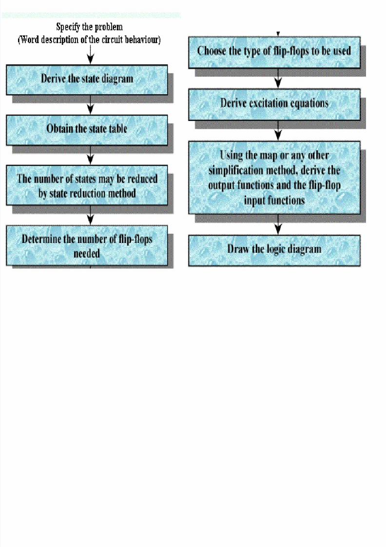
Design Procedure
• The design procedure for sequential circuits
with JK flip-flops is the same as that for
sequential circuits with D flip-flops, exceptthat the input equations must be evaluated
from the present-state to next-state
transition derived from the excitation table.

8/2/2019 Ch2Problems2
http://slidepdf.com/reader/full/ch2problems2 34/35
Design Procedure (cont)
• The advantage of using JK -type flip-flops
when designing sequential circuits is that
there are so many don’t-care entriesindicates that the combinational circuit for
the input equations is likely to be simpler,
because don’t-care minterms usually help inobtaining simpler expressions.
8/2/2019 Ch2Problems2
http://slidepdf.com/reader/full/ch2problems2 35/35
Design Procedure (cont)In order to perform the simulation, a clock, as wellas the input signals R and X, is required. In doingthe simulation of any sequential circuit, sufficienttime must be provided in the clock period for each
of the following:
1. All flip-flops and inputs to change;
2. The effects of these changes to propagatethrough the combinational logic of the circuitto the flip-flop inputs; and
3. The setup of the flip-flops for the nextclock edge to occur.