chainsaw manual l0707119.pdf
TRANSCRIPT

7/27/2019 Chainsaw manual L0707119.pdf
http://slidepdf.com/reader/full/chainsaw-manual-l0707119pdf 1/30
Do Not Throw AwayMPORTANT MANUAL,, ,,,
SEARSOperator's
Manual
Model No.358.351191
Always Wear Eye Protection
®
d_b WARNING:EAD THE OPERATOR'SMANUAL AND FOLLOW
ALL WARNINGS ANDSAFETY INS'I'RUCTIONS.FA|LURETO DO SO CAN
RESULT IN SERIOUSINJURY.
cu. in./46cc 2-CYCLE.81 inch Guide BarTurbo Air C :aner SystemGASOLINE CH SAW
• Assembly
°Operation°Customer Responsibilities
°Service and Adjustments
• Repair Parts
Sears, Roebuck and Co., Hoffman Estates, IL 60179 U.S.A.
530-083986-09/28/95

7/27/2019 Chainsaw manual L0707119.pdf
http://slidepdf.com/reader/full/chainsaw-manual-l0707119pdf 2/30
SAFETY RULES
WARNING:ALWAYS DISCONNECT SPARK PLUG WIRE AND PLACE WIRE WHERE IT CANNOT CONTACTSPARK PLUG TO PREVENT ACCIDENTAL STARTING WHEN SETTING UP,TRANSPORTING,
ADJUSTING OR MAKING REPAIRS EXCEPT CARBURETOR ADJUSTMENTS.
BECAUSE A CHAIN SAW IS A HIGH-SPEED WOOD-CUTTING TOOL, SPECIAL SAFETY PRECAU-
TIONS MUST BE OBSERVED TO REDUCETHE RISK OF ACCIDENTS. CARELESS OR IMPROPERUSE OF THIS TOOL CAN CAUSE SERIOUS INJURY.
Hearing
Snug
FittingClothing
,__ Safety Hat
Eye Protection
Heavy Duty Gloves
SafetyShoes _,_
, Chaps
Figure t
KNOW YOUR SAW- Read your operator's manual carefully until you
completely understand and can follow all safety rules,precautions, and operating instructions beforeattempting to operate the uniL
• Restrict the use of your saw to adult users whounderstand and can follow safety rules, precautions,and operating instructionsfound in this manual.
PLAN AHEAD
• Wear protective gear. Figure 1oAlways use steel-toed safety footwear with non-slip soles; snug4ittingclothing; heavy duty, non-slip gloves; eye protectionsuch as non-fogging, vented goggles or face screen;an approved safety hard hat; and sound barriers - earplugs or mufflers to protect your hearing. Regularusers should have hearing checked regularly as chainsaw noise can damage hearing
= Keep all parts of your body away from the chainwhen the engine is running.
, Keep children, bystanders, and animals a minimumof 30 feet (10 Meters) swayfrom the work area.Do notallow other people or animals to be near the chain sawwhen starting or operating the chain saw
- Do not handle or operate a chain saw when youare fatigued, ill, or upset, or if you have taken alco-hoi, drugs, or medication. You must be in goodphysical condition and mentally alert. Chain saw workis strenuous.. If you have any condition that might beaggravated by strenuous work, check with your doctorbefore operating a chain saw.
, Do not attempt to use your chain saw during badweather conditions such as strong wind, rain, snow,
ice, etc., or at night.° Carefully plan your sawing operation in advance.
Do not start cutting until you have a clear work area,secure footing, and, if you are felling trees, a plannedretreat path.
° Do not operate a chain saw that is damaged,improperly adjusted, or not completely andsecurely assembled. Always replace the hand-guard immediately if it becomes damaged, bro*ken, or is otherwise removed.
, Keep the handles dry, clean, and free of oil or fuelmixture.
o With the engine stopped, hand carry the chainsaw with the muffler away from your body, and theguide bar and chain to the rear, preferably coveredwith a scabbar&
FUEL HANDLING° Eliminate all sources of sparks or flames in the
areas where fuel is mixed, poured, or stored. Thereshould be no smoking, open flames, or work thatcould cause sparks. Allow engine to cool before refu-
eling.* Mix and pour fuel in an outdoor area on bare
ground; store fuel in a coot, dry, welt ventilated place;and use an approved, marked container for all fuel
purposes., Wipe up all fuel spills before starting saw., Move at least 10 feet (3 meters) from the fuelingsite before starting the engine.
• Do not smoke while handling fuel or while operat-
ing the saw., Turn the engine off and let your saw cool in a non-combustible area, not on dry leaves, straw, paper,etc_Slowly remove fuel cap and refuel unit.
° Store the unit and fuel in an area where fuel vaporscan not reach sparks or open flames from waterheaters, electric motors or switches, furnaces, etc
SAFETY NOTICE 1
Exposure to v brations throughprolonged use of gasoline powered hand tools could cause blood vessel or nerve damage in the|fingers, hand and joints of people prone to circulation disorders or abnormal swell ings Prolonged use in cold weather has been|linked to bood vesse damage in otherwise healthy people, if symptoms occur such as numbness, pain, loss of strength, change|in skin color or texture or loss of fee ng n the | ngers, hands or joints, discontinue the use of this tool and seek medical atten-|tion An anti-vibration system does not guarantee the avoidance of these problems. Users who operate power tools on a contin- |
ual and regular basis must monitor closely their physical condition and the condition of this unit 1
[_ LOOK FOR THIS SYMBOLTO POINT OUT IMPORTANT SAFETY PRECAUTIONS.T MEANS - AT'rENTION!!! BECOME ALERT!!! YOUR SAFETY IS INVOLVED.
-2-

7/27/2019 Chainsaw manual L0707119.pdf
http://slidepdf.com/reader/full/chainsaw-manual-l0707119pdf 3/30
SAFETY RULES
OPERATE YOUR SAW SAFELY- Do not operate a chain saw with one hand, Seriousinjuryto the operator, heipers, bystanders or any com-bination of these persons may result from one-hand-ed operation. A chain saw is intended for two-handeduse,
• Operate the chain saw only in well-ventilated out-
door areas.• Do not operate saw from a ladder or in a tree,
unless specif ically trained to do so,• Position all parts of your body to the left of cut and
away from the chain when the engine is running.• Cut wood only. Do not use your saw to pry or shove
away limbs, roots, or other objects.° Make sure the chain will not make contact with
any object while starting the engine. Never try tostart the saw when the guide bar is in a cut or kerr.
• Use extreme caution when cutting small sizebrush and saplings. Slender material can catch thechain and be whipped toward you or pull you off bal-ance,
• Be alert for springback when cutting a limb that isunder tension so you will not be struck by the limb orsaw when the tension in the wood fibers is released.
° Do not put pressure on the saw at the end of a cut°Applying pressure can cause you to lose control when
the cut is completed.- Stop the engine before sett ing the saw down,,
- Keep fuel and oil caps, screws, and fasteners securely
tightened,
MAINTAIN YOUR SAW IN GOOD WORKINGORDER° Have all chain saw service performed by your Sears
Service Center with the exceptionof lhe items listed inthe maintenance section of thwsmanual_For example, if
improper tools are used to remove or hold the ltywheelwhen servicing the dutch, structural damage to the fly-
wheel can occur and cause the flywhee! to burst° Make certain the chain stops moving when the throt-
tle trigger is released. For correction, refer to"Carburetor Adjustments,"
• Stop the saw if the chain strikes a foreign object.Inspect unit and repair or replace parts as necessary,
• Disconnect the spark plug before performing anymaintenance except for carburetor adjustments.
° Never modify your saw in any way. Use only attach-ments supplied or specifically recommended by the man-ufacturer
• Use only quality SEARS accessories and replacement
parts as recommended for this unit
TRANSPORTING AND STORAGE
• Stop the unit before transporting• Allow engine to cool, cover the guide bar and chain, and
secure theunit before storing or transporting in a vehicleo Empty fuel tank before storing or transporting the unit
Use up any fuel left in the carburetor by starting theengine and letting the engine run until it stops
° Store unit and fuel in an area where fuel vapors cannotreach sparks or open flames from water heaters, electricmotors or switches, furnaces, etc
• Store unit so the chain cannot accidentally cause injury• Store the unit outof the reach of children.
, i ,, i , ii i,iiii1,,11111,,,11 ,11
GUARD AGAINST KICKBACK - Kickback is a dangerous reaction that can lead to serious injury.
KICKBACK WARNING
KICKBACK CAN OCCUR WHEN THE MOV-ING CHAIN CONTACTS AN OBJECT ATTHEUPPER PORTION OF THE TIP OF THE
GUIDE BAR OR WHEN THE WOOD CLOSESIN AND PINCHES THE CHAIN INTHE CUT.
CONTACT AT THE UPPER PORTION OFTHE TIP OF THE GUIDE BAR CAN CAUSE
THE CHAIN TO DIG INTO THE OBJECT,WHICH STOPS THE CHAIN FOR ANINSTANT. THE RESULT IS A LIGHTNING
FAST, REVERSE REACTION WHICH KICKSTHE GUIDE BAR UP AND BACK TOWARDTHE OPERATOR. IF THE CHAIN ISPINCHED ALONG THE TOP OF THE GUIDE
BAR, THE GUIDE BAR CAN BE DRIVEN
RAPIDLY BACK TOWARD THE OPERATOR.EITHER OF THESE REACTIONS CAN
CAUSE LOSS OF SAW CONTROL WHICHCAN RESULT IN SERIOUS INJURY. DO NOTRELY ONLY ON THE SAFETY DEVICESPROVIDED WITH YOUR SAW. AS A CHAIN
SAW USER, YOU USER, YOU MUST TAKESPECIAL SAFETY PRECAUTIONSTO HELPKEEP YOUR CUTTING JOBS FREE FROMACCIDENT OR INJURY.
KickbackPath
Figure 2
AvoidObstructions
Clear The
Working Area
Figure 3
-3-

7/27/2019 Chainsaw manual L0707119.pdf
http://slidepdf.com/reader/full/chainsaw-manual-l0707119pdf 4/30
SAFETY RULES
Never ReverseHand Positions
Thumb OnUnder Side Of_
Handlebar
Elbow
Stand To
The LeftOf The Saw
It!
Figure 4
REDUCE THE CHANCE OF KICKBACK
i Recognize that kickback can happen. With a basic
understanding of kickback, you can reduce the etementof surprise which contributesto accidents.Never let the movingchain contact any object at thetip of the guide bar.Figure 2Keep the workingarea free from obstructions sucn asothertrees branches rocks fences, stumps, etc Figure
3 Eliminate or avoid any obstruction that your chaincould hit while you are cutting through a particular logorbranch
• Keep your chain sharp and properly tensioned. Aloose or dull chain can increase lhe chance of kickbackto occur Follow manufacturer's chain sharpening andmaintenance instructions Check tension at regular inter-vals with the engine stopped, never with the engine run-ning. Make sure the bar clamp nuts are securety tight-ened after tensioning the chain.
• Begin and continue cutting at full throttle, If the chainis movingat a slower speed, there is greaterchance forkickback tooccur
o Cut one log at a time.• Use extreme caution when re-entering a previouscut,
I o not attempt plunge cuts.Watch for shifting logs or other forcesthat coutd closea cut and pinch or fall _ntochain_Use the Reduced-Kickback Guide Bar and Low-
Kickback Chain specified for your sawi i I I Ill"ll'l I'm I'llllll'l ,;;;,,
MAINTAIN CONTROL
• Keep a good, firm grip on the saw with both handswhen the engine is running and don't let go. Figure4A firm grip can neutralize kickback and help you maintaincontrol of the saw Keep the fingers of your left handencirclingand your left thumb under the front handlebarKeep your right hand completely around the rear handle
whether you are right handed or left handed Keep yourleft arm straight with the elbow locked., Position your left hand onthe front handlebar so it isina straight line with your right hand on the rear han-dle when making bucking cuts. Figure 4. Neverreverse rightand left hand positionsforany type of cut-ling
• Stand with your weight evenly balanced on both feet,° Stand slightly to the left side of the saw to keep yourbody from being in a direct line with the cuttingchain, Figure4
• Donot overreach. You could bedrawn or thrownoffbal-ance and lose controlof the saw
• Do not cut above shoulder height, It is difficult tomaintain controlof saw above shoulder height.
UNDERSTANDING REACTIVE FORCES
Pinch-Kickback and Putt-ln occur when the chain issuddenly stopped by being pinched, caught, or by con-tacting a fore=gn object in the wood. Thisstopping ofthechain results in a reversal of the chain force usedto cut
wood and causesthesaw to move in the oppositedirectionof the chain rotation Either reaction can result in toss of
control and possibleserious injury.• Pinch-Kickback
- occurs when chain on top of guide bar is suddenlystopped
- rapidly drives saw straight back toward operator_° Pull-In
- occurs when the chain on the bottom of the guide baris suddenly stopped
- pulls the saw rapidly forward
KICKBACK SAFETY FEATURES
_ WARNINGHE FOLLOWING FEATURES ARE INCLUD*
ED ON YOUR SAW TO HELP REDUCE THE
HAZARD OF KICKBACK; HOWEVER, SUCHFEATURES WILL NOT TOTALLY ELIMINATETHIS DANGEROUS REACTION. AS A CHAIN
SAW USER, DO NOT RELY ONLY ON SAFETYDEVICES.YOU MUST FOLLOW ALL SAFETY
PRECAUTIONS, INSTRUCTIONS, AND MAIN-TENANCE IN THIS MANUAL TO HELP AVOIDKICKBACK AND OTHER FORCES WHICHCAN RESULT IN SERIOUS INJURY.
Reduced-Kickback Guide Bar, designed with a smelt radius t ip which
reduces the size of the kickback danger zone on the guide bar tip.Figure 5 A Reduced-Kickback Guide Bar is one which has been
demonstrated to significantly reduce the number and seriousness ofkickbacks when tested in accordance with ANSI B1751-1991
• Low-Kickback Chain, designed with acontoured depth gauge and guardl ink which detlect kickback force and al low wood to gradually ride into
the cutter Figure 5 Low-Kickback Chain is chatn which has metkickback performance requirements of ANSi B175 1-1991 when tested
on a representative sample of chain saws below 38 cubic inch dis-placement speci lied in ANS_B175 1-199I
-4-
• Handguard, designed to reduce the chance of your left hand contactithe chain if you_"hand slips off the front handlebe_t
• Position of lront and rear handlebars, designed with distance betweehandles and "in-line" with each other The spread and "in-line" position
the hands provided by this design work together to give balance aresistance in controlling the pivot of the saw back toward the operatokickback occurs.
* ANSi B175 1..1991 - Safety requirements for gasol ine powered cha
saws as set by the American National Standards Institute, lnStandard B175 1-1991
e_uced Kicld_¢k Small
Symm_tdc._l Guide et tt Rsdius Tip
Symmet_cal L_ge
Guide Br_r Radius 33p
Contoured
Depth G_uge
_P""*""-_ Guard Ltnk
KickbaCk Force
Ch_iLow"P'lc_t_< _ To Grac_ualfyRid__ntoCu_e_
I_"_-_ Can Oi:_ltucl
"_"-.,.F"r _teriat
Ch_nW_thHig_K_cld_8ckP_ent_el
Figure 5
Figure 5

7/27/2019 Chainsaw manual L0707119.pdf
http://slidepdf.com/reader/full/chainsaw-manual-l0707119pdf 5/30
CONGRATULATIONSn yourpurchaseof a SearsCraftsmanGasolineChainSaw.thasbeendesigned,engineered and manufactured to give you the best pos-sible dependability and performance.
Should you experience any probiems you cannot easilyremedy, please contact your nearest Sears ServiceCenter/Department. Sears has competent, well trainedtechnicians and the proper tools to service or repair thisuniL
Please read and retain this manual. The instructions witl
enable you to assemble and maintain your unit properly.Nways observe the "SAFETY RULES."
MODEL NUMBER: 35&351191
DATE CODEtSERIAL NO,
DATE OF PURCHASE:
THE MODEL AND SERIAL NUMBER WILL BE FOUND
ONTHE PRODUCT
YOU SHOULD RECORD BOTH SERIAL NUMBER ANDDATE OF PURCHASE AND KEEP IN A SAFE PLACEFOR FUTURE REFERENCE.
MAINTENANCE AGREEMENTA Sears Maintenance Agreement is available on this prod-uct Contact your nearest Sears Stere for details
CUSTOMER RESPONSIBILITIES= Read and observe the safety rules..• Foltow a regular schedule in maintaining, caring for, and
using your unit.• Fol!ow the instructions under "Customer
Responsibilities" and "Storage" sections of thisOperator's Manual
PRODUCT SPECIFICATIONS
GUIDE BAR:..................... 18" (46cm)
CHAIN: ............................... Low Proffie 325" Pitch
Chrome Cutters
DISPLACEMENT; .............. 28 Cubic Inches (46cc)
ENGINE: ........................... 2-cycle Air Cooled
FUEL MIX: ................... 40:t (32oz oil per galIon gas)
OILER: .......................................Automatic, 9,8 oz Tank
IGNITION: ...................... Solid State
(Air gap 010"-,0t4")
IGNITION TIMING: ................. Non-Adiustable, Fixed
SPARK PLUG TYPE: ............ Champion CJ-7Y
SPARK PLUG GAP: .............. 025" (65mm)
MUFFLER: ........................ Spark Arresting Screen
ENGINE RPM: ................... 13,200 RPM Maximum
SPECIAL NOTICEYoursaWisequippedwith a temperature limiting mufflerand spark arresting screen which meets the require-
ments of California Codes4442and 4443. Al! U,S.forestlandand the states of California, Idaho, Maine, Minnesota,
New Jersey,Washington,and Oregonrequire many internalcombustion engines to be equipped with a spark arrestorscreen by law
If you operate a chain saw in a state or locale where such
regulations exist, you are legally responsible for main-
taining the operating condition of these parts, Failure to
do so is a violation of the law, Refer to the Spark Arrestorsection under "Customer Responsibilities" for mainte-
nance,
MANUFACTURED UNDER ONE OR MORE OF THE FOLLOWING U_ pATENTS:
4 940.028 OTHER U S AND FOREIGN PATENTS PENDSNG
SPECIAL NOTICE
If this saw is to be used for commercial logging, you must order and install a Chain Brake, to comply with
Federal OSHA Regulations for Commercial Logging. See Repair Parts List or call 1-800-235-5878,
FULL ONE YEAR WARRANTY ON GAS CHAIN SAW
For one year from the date of purchase, when this Craftsman Gas-Powered Chain Saw is maintained, lubricated,andtuned-up according to the owner's manual, Sears will repair, free of charge, any defect inmaterial or workmanship.
This warranty excludes bar, chain, spark plug, and air filter, which are expendable parts and become worn during normalUse
If this Gas Chain Saw is used for commercial or rental purposes, this warranty applies for only 30 days from the date of
purchase
WARRANTY SERV{CE IS AVAILABLE BY RETURNING THIS CHAIN SAW TO THE NEAREST SEARS SERVICECENTER IN THE UNITED STATES
This warranty gives you specific legal rights, and you may also have other rights which vary from state to state.
SEARS, ROEBUCK AND CO,, D/817WA, HOFFMAN ESTATES, IL 60179
-5-
7/27/2019 Chainsaw manual L0707119.pdf
http://slidepdf.com/reader/full/chainsaw-manual-l0707119pdf 6/30
= = i = , i n ,= i =,=,=r=,l,,,,,n,,r,,n,= =
TABLE OF CONTENTSsafe_ 'Ruies i.,,_,,ii_ii_iiii _ir, i,iiii*ii,iiiii_iiii,i [/i_.,[.,iiii,,,,_ii_2 Customer ResponsiSiiitiesi,.,,,i,,ii_i_iioi,ii,.iill .......................g
Product Specification ..................................................................................Service and Adjustments .............................................................. 24Warranty ..................................................................................... Storage ......................................................................................9Accessories ................................................................................ Trouble Shooting Points ....................................... ...... .............. 30Assembly .........................................................................................Repair Parts ..............................................................................1
...................................................... 10 Repair Parts Ordering/Service ....................... Back Cover,,11,1,1111 1,111, i1,1 i, i i i
INDEXi1,1 ,,i, i i , ,,i ,11,1,11111,, i ,111,1,,,i,,,,,11,,i I i i1,1 i
AAccessories .............................................................................Air Filter .................................................................................2
Assembly .................................. .............................................. 8
BBar and Chain Oif ................................................................. 12
Bucking ..................................................................................... 17C
Carburetor Adjustments ................................................................7Carton Contents ...............................................................................Chain Oiler .................................................................................1
Chain Sharpening ............................................................ 20Chain Adjustment ...................................................................4Customer Responsibilities ..................................................19
E
EngineFuel/Oil ............................................................................... 12
Spark Plug . . . . . . . . . .. . . . . .. . . . . .. . . . . .. . . . . .. . . . . .. . . . . .. . . . . .. . . . . .. . . . . . .. . . . . .. 22Starting ................................................................................. 13Storage .......................................... ........................................... .9
FFuel Filter ...................................... ....... ........................................ 23
Fueling ............................................ .. ....................................... .... 12G
Guide Bar and Chain Oil .....................................................2Guide Bar Maintenance ........................................................1
HHow To Use Your Chain Saw .....................................................1
K
Know Your Chain Saw .............................................................0L
Lirabing ....................................... ........................................... ......8M
Maintenance Schedule .........................................................9Model Number ............................................................................Muffler ..................................... ........................................... .........2
O
Ope ration ............................................................................t0Ordering Repair Parts ..............................................ack Cover
P
Product Specifications ......................................................... 5
Pruning ...................................................................................8R
Repair Parts ...............................................................................1S
Service and Adjustments ..........................................................4Spark Arrestor Screen ..............................................................2Starter Rope ...............................................................................5Starting ....................................... ........................................... ......3Storage . . . . . . . . . . . .. . . . . .. . . . . .. . . . . .. . . . . .. . . . . .. . . . . .. . . . . . .. . . . . .. . . . . .. . . . . .. . . . . .. . . . . .. . . . . . 29
T
Throttle Control Group ..........................................................1Tree Felling .................................................................................5Trouble Shooting Points ...................................................30
W
Warranty .............................................................. ....................... 5
,=1== .....................
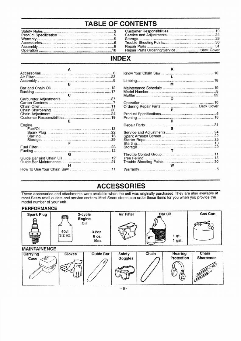
ACCESSORIESThese accessories and attachments were available when the unit was o';iglnatly purchas'ed They are also available at
most Sears retail outlets and service center& Most Sears stores can order these items for you when you provide the
model number of your unit.,
PERFORMANCE
Spark Plug 2-cycle
_ Engine
Oil
3.2oz.
8 ozo
16ozo
Air Filter Bar Oil
1 qt,
1 gaL
Gas Can
MAINTAINENCE
Carrying _ Gloves Guide Bar Safety
Goggles
Chain HearingProtection
Chain
Sharpener
-6-
7/27/2019 Chainsaw manual L0707119.pdf
http://slidepdf.com/reader/full/chainsaw-manual-l0707119pdf 7/30
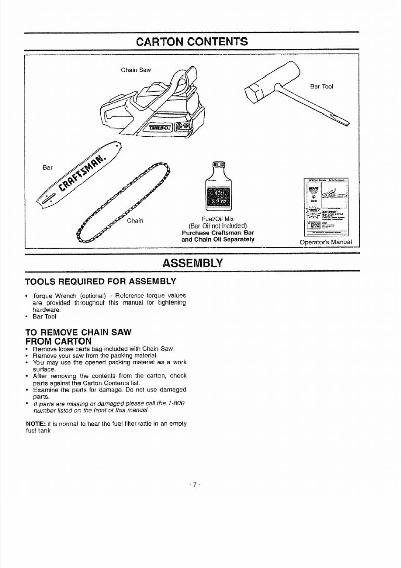
CARTON CONTENTSi i i i i i i ii ii ii ii ii i
Chain Saw
Chain Fuel/Oil Mix
(Bar Oil not included)Purchase Craftsman Bar
and Chain Oil Separately Operator's Manual
ASSEMBLY, i ul ,l , i,i ................. i i ,i, i ,,11111
TOOLS REQUIRED FOR ASSEMBLY
• Torque Wrench (optional) - Reference torque values
are provided throughout this manual for tighteninghardware.
• Bar Toot
TO REMOVE CHAIN SAW
FROM CARTON• Remove loose parts bag includedwith Chain Saw
• Remove your saw from the packing material.
• You may use the opened packing material as a worksurface
= After removing the contents from the carton, check
parts against the Carton Contents list.
• Examine the parts for damage.. Do not use damagedparts.
° If parts are missing or damaged please call the 1-800number listed on the front of this manual
NOTE: it is normal to hear the fuel filter rattle in an emptyfuel tank
-7-

7/27/2019 Chainsaw manual L0707119.pdf
http://slidepdf.com/reader/full/chainsaw-manual-l0707119pdf 8/30
ASSEMBLY
_ ANGER:
DO NOT START THE ENGINE WITHOUTTHE GUIDE BAR AND CHAIN COM-
PLETELY ASSEMBLED. OTHERWISE,THE CLUTCH CAN COME OFF ANDSERIOUS INJURY CAN RESULT.
ALWAYS WEAR GLOVES WHEN HAN-DLING THE CHAIN.THE CHAIN CAN BE
SHARP ENOUGH TO CUT YOU EVEN
THOUGH IT ISTOO DULLTO CUTWOOD.
HOW TO ASSEMBLE YOUR CHAIN SAW
BAR AND CHAIN ASSEMBLY (Fig.6-12)• Loosen and remove the 2 bar clamp nuts,
• Remove bar clamp
= Remove and throw away blue shipping spacer,
• Turn adjusting screw by hand counterclockwise until
adjusting pin just touches the stop.• Mount guide bar with slotted end over both guide bar
mounting bolts, Slide guide bar behind clutch drum untilguide bar steps against the clutch drum sprocket, Install
the bar with "Craftsman" logo in up position(see Fig 8)
• Carefully remove chain from bag Position chain with the
drive links as shown Fig_9,
• Place chain over and behind the clutch drum Fig,10, Fit bottom of drive links between teeth in sprocket nose
• Fit chain drive links into top of guide bar Fig,9,
Figure 6
Clutch DrumGuide Bar
Mounting Bolts
Figure 8
Guide Bar
Gauge
Drive
SprocketNose
CRRFTSMRN
Clutch DrumGuide Bar
Mounting Bolts
Guide Bar
Figure 9
AdjustingScrew
Adjusting StopPin
Figure 7
ChainBehind theClutch Drum
Figure 10
-8-

7/27/2019 Chainsaw manual L0707119.pdf
http://slidepdf.com/reader/full/chainsaw-manual-l0707119pdf 9/30
ASSEMBLY
o Pull guide bar forward until chain is snug in guide barqrooves
i low, install bar clamp making sure the adjusting pin isposit ioned in the lower hole in the guide barInstall two (2) bar clamp nuts finger tight.Now proceed to the "Chain Adjustment" section
Bar Clamp
Guide Bar
CRRFT_MRN.-
jt
/
// Lower Hole
Figure 11
CRRFTSMRN°
Bar Clamp Nuts
Figure 12
CHAIN ADJUSTMENT (Fig. 13, 14 & 15)Roll chain around guide bar to ensure kinks do not exist,(rotates freely)
Assure bar clamp nuts are loosened (finger tight).Turn adjusting screw clockwise until chain just barelytouches the bottom of guide bar
• Roll chain around guide bar to ensure all links are in bargroove,
• Lift up tip of guide bar to check for sag..Release tip ofguide bar, then turn adjusting screw 1/4 turn clockwise.Repeat this step until sag does not exist.
• While lifting tip of guide bar, t ighten bar clamp nuts withthe bar tool (provided)Torque 10-15 ft-lbs
Bar Clamp Nuts
:RR
_'_G uide Bar
Adjusting Screw
AdjustingScrew
1/4 Turn
Guide Bar
Bar Toot_
Bar ClampNuts
Figure t4To check chain tension:• Use the screwdriver end of the bar tool to move chain
around the guide bar.- If chain does not rotate, it is too tight - slightly loosen
bar clamp nuts and turn adjusting screw 1/4 turn coun-
terclockwise. Retighten bar clamp nuts., tf chain is too loose, loosen bar clamp nuts; then, turn
adjusting screw 1/4 turn clockwise Lift up tip of guidebar to check for sag Retighten bar clamp nuts..
Bar Tool
Bar ClampNuts Screw Guide Bar
Figure 15NOTE: It is normal for a new chain to stretch. Because of
this initiat stretch during the first 15-30 minutes of opera-tion, you should recheck your chain tension frequentlyand adjust the chain tension as required (See "ChainTension" section).
CHECK LIST• Check for loose fasteners and parts
Check for damaged or worn parts.
Check chain tension• Check chain sharpness• Guide Bar maintenance
° Check guide bar lube
Refer to "Customer Responsibilities" for further adjust-ments and recommendations
Figure 13 - 9 -

7/27/2019 Chainsaw manual L0707119.pdf
http://slidepdf.com/reader/full/chainsaw-manual-l0707119pdf 10/30
OPERATION
KNOW YOUR CHAIN SAW (Fig, 16)READ THIS OPERATOR'S MANUAL AND SAFETY RULES BEFORE OPERATING YOUR CHAIN SAW. Compare the
illustrations with your unit to familiarize yourself with the location of the various controls and adjustments° Save thismanual for future reference,.
_HAND GUARD FRONT
/ _.,_/HANDLE STARTER
/ L"_ ROPE HANDLE
CHAIN r _ _ t SWITCH
" "-,\ A'F1LLCAP J F U|JlIIIIItlt 7._ _- | /,_,_.,,,=
- , o
CYLINDER AND AIR FILTER
COVER 1
THROTTLE
LOCKOUT
/
STARTERHOUSING
MUFFLER
ADJUSTINGSCREW
REAR
HANDLE
FUEL MIX
FILL CAP
CHAIN TRAVEL
DIRECTION
{:RRFTSMRN
THROTTLETRIGGER BAR CLAMP
BAR CLAMPNUTSHOKE!
FAST,IDLE
CONTROL
I\1Figure 16
Listed by Underwriters Laboratories, Inc.
in accordance with American National Standards for Gasoline-Powered Chain Saws Safety Requirements
(ANSI B175.14991).
GUIDE BAR
The ON/STOP SWITCH is used to stop the engine,
The STARTER ROPE HANDLE is used for starting theengine.
The CHOKE/FAST IDLE CONTROL provides addition-
al fuel to the engine when stating a cold engine, andsets the thrott le to "Fast Idle" position
The THROTTLE LOCKOUT prevents the THROTTLE
TRIGGER from being squeezed accidentally
The THROTTLE TRIGGER controls engine speed and
disengages the CHOKE/FAST IDLE control if set.
The GUIDE BAR is designed to carry the chain.
The CUTTERS are designed to cut the wood.
The BAR CLAMP NUTS are designed to hofd the
guide bar after adjustments have been completed.
The ADJUSTING SCREW is designed to tension the
chain around the guide bar.
-10-

7/27/2019 Chainsaw manual L0707119.pdf
http://slidepdf.com/reader/full/chainsaw-manual-l0707119pdf 11/30
OPERATION
HOW TO USE YOUR CHAIN SAW
STOPPING YOUR ENGINE
- Move on/stop switch tothe "STOP" position,
- If engine does not stop, pull blue choke knob out fully
CHAIN OILER (Fig. 17)• The chain oiler provides continuous lubrication to the
chain and guide bar Be sure to fill the bar oil tank
when you fill the fuel tank (Capacity=98 fLoz,)
• Your chain saw will consume approximately one tankof bar oil for each tank of fuel used.
Your chain oiler is automatic and requires no adjustment
Bat
capX
Front Handle Fuel Mix Fiil Cap
Figure 17
THROTTLE CONTROL GROUP (Fig. 18 & 19)
THROTTLE LOCKOUT
• The throttle lockout prevents unintentional actuation of
the throttle trigger.
• You must depress the throttle lockout with the palm of
your hand before actuating the throttle trigger.
Thrott{e /A
L_o_I _ _=_
Trigger
!/
Figure 18
CHOKE/FAST IDLE SPEED
• The choke and fast idle speed are set by pulling the
choke lever out fully for cold or refueled engine starts,• Squeezing the throttle trigger will release the choke
and fast idle settings.,If the throttle trigger is squeezed
accidentally during starting, it will be necessary to
reset throttle advance by pulling choke lever out fully°
__ Choke Pos_lons
I U '-'Off Full
I o sto,
Figure 19
THROTTLE TRIGGER
" The throttle trigger allows for variable control of
engine speed°
• The throttle trigger is actuated by the index finger on
your right hand (After the throttle lockout isdepressed),
-1!

7/27/2019 Chainsaw manual L0707119.pdf
http://slidepdf.com/reader/full/chainsaw-manual-l0707119pdf 12/30
OPERATION
BEFORE STARTING ENGINE:
WARNING:BE SURE TO READ THE FUEL HANDLING
INFORMATION IN THE SAFETY RULESSECTION ON PAGE 2 OF THIS MANUAL
BEFORE YOU BEGIN.
IF YOU DO NOT UNDERSTAND THE FUEL
HANDLING SECTION DO NOT ATTEMPT
TO FUEL YOUR UNIT; SEEK HELP FROMSOMEONE THAT DOES UNDERSTAND
THE FUEL HANDLING SECTION OR CALL
THE CUSTOMER ASSISTANCE HOTLINE
AT 1-800-235-5878.
GUIDE BAR AND CHAIN OIL
For maximum guide bar and chain life, we recommendyou use Craftsman chain saw bar oil If Craftsman bar oil
is not available, you may use a good grade SAE30 oil
until you are able to obtain Craftsman brand.The oil out-
pul is automatically metered during operation..Your sawwill use approximately one tank of bar oil for every tank
of fuel mix.. Always fill the bar oil tank when you fillthe fuel tank.
GASOLINE
The two-cycle engine on this product requires a fuelmixture of regular unleaded gasoline and a high quality
40:1 2-cycle engine oii (AIR-COOLED) for lubrication of
the bearings and other moving parts. The correct fuelioi i
mixture is 40:1 (see Fuel Mixture Chart). Too littleoil orthe incorrect oil type will cause poor performance and
may cause the engine to overheat and seize.
Gasoline and oil must be premixed in a clean approved
fuel container Always use fresh regular unleaded gaso*line.
This engine is certified to operate on unleaded gasoline.
IMPORTANT:Experience indicates that alcohol blended
fuels called gasohol (or using ethanol or methanol) can
attract moisture, which leads to oii/gas separation and
formation of acids during storage., Acidic gas can dam-age the fuel system of an engine while in storage To
avoid engine problems, the fuel system should be emp-
tied before storage for 30 days or longer Drain the gastank, then run the fuel out of the carburetor and fuel
lines by starting the engine and letting it run until itstops. Use fresh fuel next season.. See STORAGE
instructions for additional information Never use engineor carburetor cleaner products in the fuel tank or per-
manent damage may occur
FUEL STABILIZER
Fuel stabilizer isan acceptable alternative in minimizing
the formation of fuel gum deposits during storage.. Add
stabilizer to gasoline in fuel tank or storage container
Always follow the fue! mix ratio found on the stabilizercontainer. Run engine at least 5 minutes after addingstabilizer to allow the stabilizer to reach the carburetor.
You do net have to drain the fuel tank for storage if you
are using fuel stabilizer_.
CRAFTSMAN 40:1 2-cycle engine oil (AIR-COOLED) is
specially blended with fuel stabilizers° If you do not usethis Sears oil, you can add a fuel stabilizer to your fueltank.
40:1 2-CYCLE AIR-COOLED ENGINE OIL
CRAFTSMAN 40:1 2-cycle engine oil (AIR-COOLED) is
strongly recommended.This oil is specially blended withfuel stabilizers for increased fuel stability (extends fuel
life up to 5 times longer) and reduced smoke
If CRAFTSMAN 40:1 2*cycle engine oil (AIR-COOLED)is not available, use a good quality 2-cycle engine oil(AIR-COOLED) that has a recommended fuel mix ratioof 40:1.
IMPORTANT! Do not use:
- AUTOMOTIVE OIL
• BOAT OILS (NMMA, BIA, etc.)
These oils do not have proper additives for 2-cycle (AIR-
COOLED) engines and can cause engine damage
GASOLINE AND OIL MIXTURE
Mix gasoline and oil as follows:
- Consult chart for correct quantities.• Do not mix gasotine and oil directly in the unit's fueltank
FOR ONE GALLON:
= Pour 3.2 ounces of high quality, 40:1 2-cycle engine
oil (AIR-COOLED) into an empty, approved one gatton
gasoline container.
• Add one gallon of regular unleaded gasoline to thegallon container, then securely replace the cap.
, Shake the container momentarily.
° The mixture is now ready for use. Fuel stabilizer can
be added at this time if desired; follow mixing instruc-tions on the label.
FUEL MIXTURE CHART40:1 Fuel:O!! Mix Ratio
Gasoline
1 galton 3-2
2..°5gallons 8.0
NOTE: Fuel containers may hold more than the speci-
fied amount.. If too much gasoline is in the container,
the resulting gas-to-oil fuel mixture will not be correctfor proper engine operation.
-12-

7/27/2019 Chainsaw manual L0707119.pdf
http://slidepdf.com/reader/full/chainsaw-manual-l0707119pdf 13/30
OPERATION
STOPPING YOUR ENGINE
o Move on/stop switch to the "Stop" position
. If engine does not stop, pull blue choke knob out fully
WARNINGLWAYS WEAR GLOVES, SAFETYFOOTWEAR, SNUG-FITTING CLOTHING,
AND EYE, HEARING, AND HEADPROTECTION DEVICES WHEN OPERAT_
tNG A CHAIN SAW.
THE CHAIN MUST NOT MOVE WHEN THE
ENGINE RUNS AT IDLE SPEED. REFER
TO THE "CARBURETOR ADJUST-
MENTS" SECTION FOR CORRECTION.
AVOID ANY CONTACT WITH THE MUF-FLER. A HOT MUFFLER CAN CAUSE
SERIOUS BURNS.
NOTE: Check chain tension using instructionsin the
"Service and Adjustment' section,• Before first use.
= After 1 minute of operation,
TO START ENGINE (Fig. 20 & 21)
COLD ENGINE START AND WARM ENGINESTART AFTER RUNNING OUT OF FUEL
° Fuel engine with40:1 fuel mix (3.2 oz.to 1 gaLgas).o Fill bar oil tankwith bar oil,Your saw will use approxi-
mately one tank of bar oil for each tank of lueI mix
,, Turn on ignitionby moving on/stop switch to the "On"
position,• Pull the blue choke/fast idlecontrol out fully to set both the
choke and fast idle for starting,Then set the saw on theground,Grip the front handle with your left hand and place
your rightfoot through the opening inthe rear handle.• IFTHROTTLETRIGGER IS SQUEEZED ACCIDENTALLY
DURINGSTARTINGITWILL BENECESSARYTO RESET
I_HECHOKE/FASTIDLE CONTROL.
NOTE - When pulling the starter rope, do not use the fu]f
extent of the rope as lhis can cause the rope to break. Do
not let the starter snap back, hold the handle and let the
rope rewind slowiy• Pull starter rope handle with your right hand until the
engine attempts to start.
• Push the choke knob in to the "Off" position,
,, Continue to pullstarter rope handle until engine starts.
• Then, allow engine to run for approximately 5 seconds.
° Then, squeeze and release throttle trigger to allow engineto idle.
• To stop engine, move on/stop switch to the "Stop" posi-tion,
I Choke Positions
iS-. ....\;tl _,_ "_._ t On/Stop
STARTING A WARM ENGINE• Move on/stop switch to the "On" position
• Engage the choke/fast Idle by pulling out the bluechoke knob fully and pushingit back in fully
• With saw on ground, grip front handle with left hand
and place your right foot through opening in rear han-
dle-° Pull starter rope handle until engine starts_
• Squeeze and release thrott le trigger to return engine to
idle speed,,
Right Handon
StarterRope Handle
STAR'rING POSITION
Left Hand
on
Front Handle
Right Foot Through Opening In Rear Handle
Figure 21
DIFFICULT STARTING OR FLOODED ENGINE
The enginemay be flooded withtoomuch fuel ifit has not
started after 10pulls,with the choke in the full out position
Flooded engines can be cleared of excess fuel withthe fol-
lowing procedure:
• Pullout the blue choke/fast idlecontrol fully and then pushit back intothe off position to set the fast idle control to the
start position.
= Verify that the on/stop switch isin the "On" position.
. With saw on ground, grip front handle with left hand andplace your right foot throughopening in rear handte_
• Pull starter ropehandle until engine starts_
Starting could require pulling starter rope handle many
times depending on how badly unit is flooded.
If engine still fails to start, refer to "TROUBLE SHOOTING"chart or call the 1-800 number listed on the front page of this
manual,
Figure 20 - 13 -
7/27/2019 Chainsaw manual L0707119.pdf
http://slidepdf.com/reader/full/chainsaw-manual-l0707119pdf 14/30
OPERATION
GENERAL OPERATION TIPS. Cut wood only,Do not cut metal; plastics; masonry; non-
wood building materials; etc.
• Stop the saw ff the chain strikes a foreignobject, Inspect
the saw and repair or replace parts as necessary. Keep the chain out of dirt and sand Even a small amount
of dirt will quickly dull a chain and thus increase the pos-sibility of kickback.
To get the "feet"of using your saw before you begin a majorsawing operation, practice cutting a few small logs using the
following technique:
o Accelerate engine to full throttleby squeezing the throttle
trigger before entering cut.
o Never cut with engine at partial speeds.
• Begin cutting with the saw chassis against the log,,• Keep engine at full throWeduring cutting procedure,
- Allow the chain to cut for you; exert only l ight downward
pressure,tfyou force the cut, damage to the bar,chain, orengine can result.
• Release the throttletriggeras soon as the cut is complet-
ed, allowing the engine to idle If you run the unit at fullthrottle without cutting, unnecessary wear can occur to
the chain, bar, and engine• To avoid losingcontrol when completing the cut, do not
put pressureon the saw during the end of Ihe cut.
. Stop engine before setting unit down after operation,
OPERATION SAFETY
WARNING
tF SAW BECOMES PINCHED OR HUNGtN A LOG, DO NOT TRY TO FORCE ITOUT, YOU CAN LOSE CONTROL OFTHE
SAW RESULTING IN INJURY AND/OR
DAMAGE TO THE SAW°STOP THE SAW,DRIVE A WEDGE OF PLASTIC OR
WOOD INTO THE CUT UNTIL THE SAW
CAN BE REMOVED EASILY. RESTART
THE SAW AND CAREFULLY REENTER
THE CUT. '1"OAVOID KICKBACK AND
CHAIN DAMAGE, DO NOT USE A METAL.WEDGE, DO NOT ATTEMPT TO
RESTART YOUR SAW WHEN IT ISPINCHED OR HUNG IN A LOG.
KICKBACK CAN OCCUR WHEN THEMOVING CHAIN CONTACTS AN OBJECT
ATTHE UPPER PORTION OFTHETIP OF
THE GUIDE BAR OR WHEN THE WOOD
CLOSES IN AND PINCHES THE SAWCHAIN IN THE CUT_ CONTACT AT THE
UPPER PORTION OF THE TIP OF THE
GUIDE BAR CAN CAUSE THE CHAIN TO
DIG INTO THE OBJECT AND STOP THE
CHAIN FOR AN INSTANT°THE RESULT
IS A LIGHTNING FAST, REVERSE REAC-TION WHICH KICKS THE GUIDE BAR UP
AND BACK TOWARD THE OPERATOR. IF
THE SAW CHAIN IS PINCHED ALONG
THE TOP OF THE GUIDE BAR, THEGUIDE BAR CAN BE DRIVEN RAPIDLY
BACK TOWARD THE OPERATOR°
EITHER OF THESE REACTIONS CAN
CAUSE LOSS OF SAW CONTROL
WHICH CAN RESULT IN SERIOUS
INJURY,
AVOID REACTIVE PINCH FORCESPinch-Kickbackand Pull-in occurwhen the chain is sudden-
ly stopped by being pinched, caught, or by contacting a for-
eign object in the wood This sudden stopping of the chainresults in a reversal of the chain forceused to cut wood and
causes the saw to move in the opposite direction of the
chain rotation. Pinch-Kickbackdrives the saw straight back
toward the operator,PuIl-ln pulls the saw away from the
operator Either reaction can result in loss of control and
possiblyserious injury
TOAVOID PINCH-KICKBACK:
° Be extremely aware of situations or obstructions that can
cause material to pinch the top of or otherwise stop thechain
• Do not cut more than one log at a time° Do not twist the saw as the bar is withdrawn from an
under-cut when bucking
TO AVOID PULL-IN
• Always begin cutting withthe engine at full throttleand the
saw housing against wood,
• Use wedges made of plastic or wood, (never of metal) toholdthe cut open_
-14-

7/27/2019 Chainsaw manual L0707119.pdf
http://slidepdf.com/reader/full/chainsaw-manual-l0707119pdf 15/30
OPERATION
TREE FELLING
_ ARNINGF THE TRUNK OR LIMBS ARE ROTTING,THEY CAN FALL UNEXPECTEDLY ANDCAUSE SERIOUS INJURY.,
AS YOU MAKE YOUR FELLING CUT, IFTHE SAW APPEARSTO BE BINDING,THETREE IS STARTING TO FAI_L IN THEWRONG DIRECTION. IMMEDIATELY STOPTHE SAW AND USE A FELLING WEDGE
AND MAUL (HAMMER) TO FORCE THEFELLING CUT OPEN. THE WEDGE WILLHOLD THE FELLING CUT OPEN ALLOW-ING YOU TO REMOVE THE SAW. KEEPEVERYONE AWAY FROM THE TREE INALL DIRECTIONS.
Bottom
Notch
Cut
III
Buttress
Root
DETERMINE THE NATURAL FALL DIRECTION
• Wind - A tree evenly balanced wilt fall in the same
direction the wind is blowing,
• Lean - Use a carpenter's level or plumb bob to deter-mine if tree has a natural lean, A leaning tree wilt tendto fall in direction of lean.
- Shape - A tree will tend to fall towards side that is more
heavily branched
- Other Factors - Contacting nearby trees, buildings, orwires can influence the direction the tree will fall
CUTTING PROCEDURE (Fig. 22)After determining the Natural Fall Direction, the freeshould be cut as follows:
IMPORTANT: BEFORE FELLING A TREE, MAKE SUREYOU HAVE AT LEAST 3 FELLING WEDGES AND A
MAUL (HAMMER) AVAILABLE FOR USE IF NEEDED
• Use some means to visually mark the Natural FallDirection.
o Mark your notch cut on the Natural Fall Direction side of
the tree approximately 18-24 inches above the ground
• Cut top of the notch first at a 45 degree angle, Saw
through 1/3 of the width of the tree,
• Cut bottom of the notch at a 45 degree angle until youmeet the top notch cut Remove notch of wood
• On the side of the tree opposite the notch cut, make the
telling cut, The felling cut should be 2 inches above the
center point of the notch cuL Before the felling cut iscomplete, use wedges to open the cut when necessary
to control the direction of the fall, Use wood or plasticwedges, but never steel or iron, to avoid kickback andchain damage
. Cracking sounds, widening of the felling cut, movement
in the upper branches are all signs that the tree is readyto fall
• As tree begins to fall, turn off saw, and move quickly
away from direction of fall,
Figure 22
tf your chain saw binds in the felling cut, you have three
options:
• If the wrong direction of fall is acceptable, carefully
remove the felling wedge, Cut deeper in the notch sideof the tree until tree starts to fall,
• If the wrong direction of fall is not acceptable, attempt
to use one or more felling wedges to force the tree in
the original direction of fall Do so by driving the wedges
deeper into the felling cut.
. Keep everyone away from the tree in all directions and
then seek professional help!
FELLING TIPS• Clear the work area of debris where you can have
secure footing,o Make sure there is enough room for the tree to fall.
Maintain a distance of 2 1/2 tree lengths from the near-
est person orother objects. Engine noise can drown out
a warning call
- Remove dirt, stones, loose bark, nails, staples, andwire from the tree where cuts are to be made,,
° Plan to stand on the up-hill side when cutting on a
slope.- Plan a clear retreat path to the rear and diagonal to the
line of fai l
- Large buttress roots should be removed prior to notchcut-
. Use a wedge if there is any chance that the tree will not
fail in the desired direction.• We recommend you cut branches below shoulder
height before fell ing tree.,(See Limbing and Pruning),
Be alert to signs that the tree is ready to fall:
• Cracking sounds,
• Widening of the felling cut° Movement in the upper branches.
-15-

7/27/2019 Chainsaw manual L0707119.pdf
http://slidepdf.com/reader/full/chainsaw-manual-l0707119pdf 16/30
OPERATION SAFETY
FELLING SAFETYDON'T PUT YOURSELF INTHESE POSITIONS
t_
Check the wind--Don't cut down wind
Check the lean--Don't cut on lean side
Check the balance--
Don't cut onweighted side
_ ARNINGO NOT CUT:-NEAR ELECTRICAL WIRES OR BUILD-INGS.
-IFYOU DO NOT KNOWTHE DIRECTIONOFTREE FALL.
- AT NIGHT.- DURING BAD WEATHER - RAIN, SNOW,STRONG WIND, ETC.
o Look for decay and rot. If the trunk is rotted, it cansnap and fall toward the operator,
• Check for broken or dead branches which can fall on
you while cutting
• Be extremely cautious with partially fallen trees that
may be poorly supported, When a tree doesn't fal_com-
pletely, set the saw aside and pull down the tree with acable winch, block and tackle, or tractor To avoid injury,
do not cut down a partially fallen tree with your saw
-16-

7/27/2019 Chainsaw manual L0707119.pdf
http://slidepdf.com/reader/full/chainsaw-manual-l0707119pdf 17/30
OPERATION
BUCKINGBucking is cutting a fallen tree to the desired tog size.L
TYPES OF CUTTING (Fig. 23)
• Overcutting - begin on the tep side of the tog with the
bottom of the saw chassis against the tog; exert lightpressure downward• Undercutting - begin on the underside of the togwith
the top of the saw chassis against the log; exert lightpressure upward. During undercutting, the saw wil l tend
to push back al you Be prepared for this reaction and
hold the saw firmly to maintain control,
Undercut
Saw Chassis
Figure 23
BUCKING ON THE GROUND (Fig. 24)• Overcut with a t/3 diameter cut.
• Roll tog over and finish with an overcut.
Figure 24
BUCKING USING A SUPPORT (Fig. 25 & 26)Another log or a stand, such as a sawhorse, may be usedas supports when bucking• Area A - Undercut 1/3 of the way through the log.
- Finish with an overcuL
• Area B - Overcut 1/3 of the way through the Iog_
- Finish with an undercut..
F A_,I_-_ B
2nd Cut 1stCut
I stCut
Sawhorse
Figure 25
1st Cut Cut
Another Log • • -_ ....
Figure 26
BUCKING TIPS
o Cut only one log at a time.o Cut shattered wood very carefully. Sharp pieces of
wood could be flung toward the operator.• Use a sawhorse to cut small logsoNever alfow another
person to hold the log while cutting and never hold thelog with your leg or foot.
• Do not cut in an area where logs, limbs, and roots aretangled such as in a blown down area. Drag the logsinto a clear area before cutting by pulling out exposedand cleared logs first_
• Give special attention to logs under strain to prevent thesaw from pinching Make the first cut on the pressureside to relieve the stress on the log.
OPERATION SAFETY
F__ ARNING
O NOT STAND ON THE LOG BEING CUT.ANY PORTION CAN ROLL CAUSINGLOSS OF FOOTING AND CONTROL°
NEVER TURNTHE SAW UPSIDE DOWNTOUNDERCUT.THE SAW CANNOT BE CON-TROLLED INTHIS POSITION.
BUCKING SAFETY° Stay on uphilt side of tree when cutting
Use Common Sense Maintain Secure Footing
-17-
7/27/2019 Chainsaw manual L0707119.pdf
http://slidepdf.com/reader/full/chainsaw-manual-l0707119pdf 18/30
OPERATION
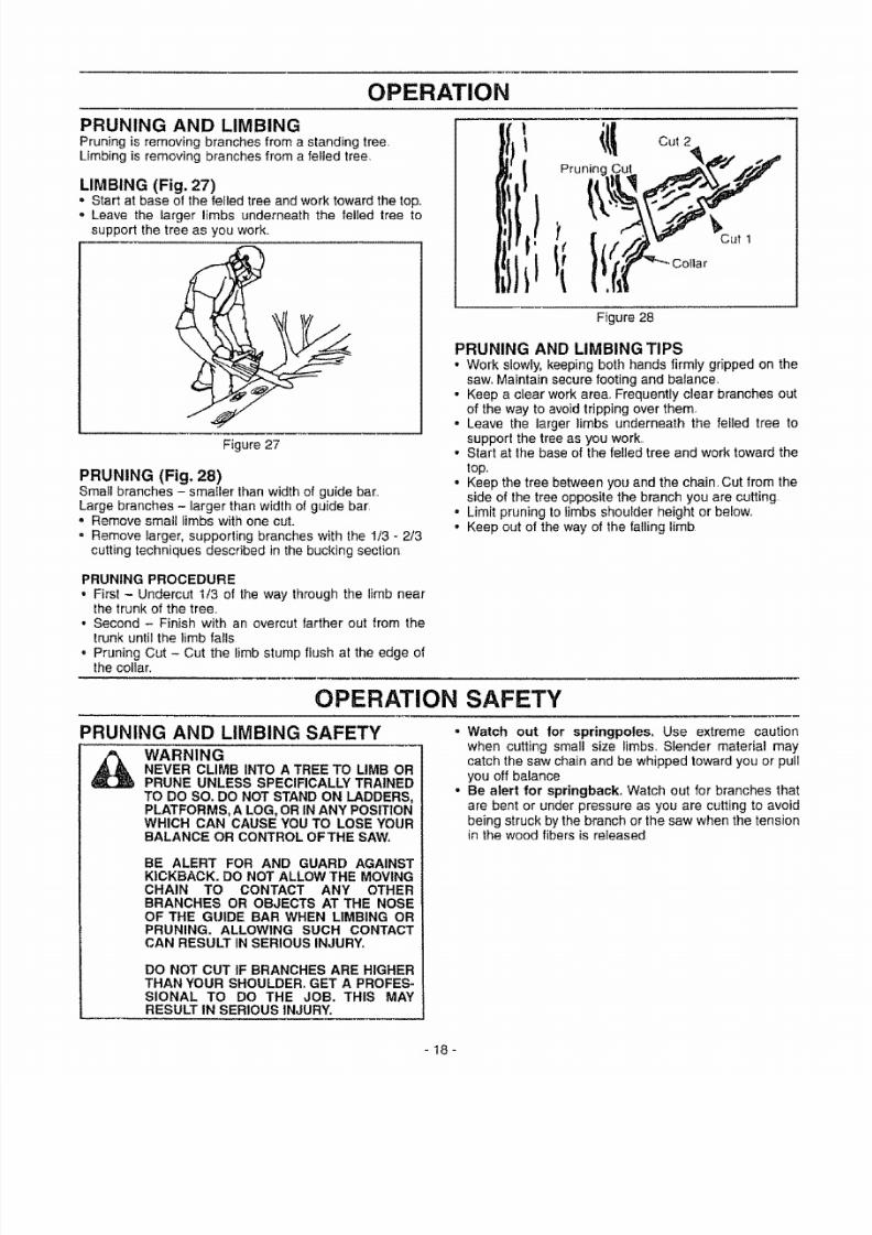
PRUNING AND LIMBINGPruning is removing branches from a standing tree,Limbing is removing branches from a felled tree.
LIMBING (Fig. 27)', Start at base of the felled tree and work toward the top°
° Leave the larger limbs underneath the felled tree tosupport the tree as you work.
Figure 27
PRUNING (Fig. 28)Small branches - smaIler than width of guide bar,,Large branches - larger than width of guide bar,° Remove small limbs with one cut.
= Remove larger, supporting branches with the 1/3 - 2/3
cutting techniques described in the bucking section
i_ Cut 2
Cut
)It
Cut 1
Figure 28
PRUNING AND LIMBING TIPS
• Work slowly, keeping both hands firmly gripped on thesaw. Maintain secure footing and balance.
• Keep a clear work area., Frequently clear branches out
of the way to avoid tripping over them.
• Leave the larger limbs underneath the felled tree tosupport the tree as you work,,
• Start at the base of the felled tree and work toward the
top,,
° Keep the tree between you and the chain. Cut from the
side of the tree opposite the branch you are cutting
= Limit pruning to limbsshoulder height or below.
• Keep out of the way of the falling limb
PRUNING PROCEDURE
• First - Undercut t/3 of the way through the limb nearthe trunk of the tree.,
• Second - Finish with an overcut farther out from the
trunk until the limb fails• Pruning Cut - Cut the limb stump flush at the edge of
the collar.
OPERATION SAFETY
°PRUNING AND LIMBING SAFETY
_ ARNINGEVER CLIMB INTO A TREE TO LIMB ORPRUNE UNLESS SPECIFICALLY TRAINED
TO DO SO. DO NOT STAND ON LADDERS,PLATFORMS, A LOG, OR INANY POSITIONWHICH CAN CAUSE YOU TO LOSE YOURBALANCE OR CONTROL OFTHE SAW.
BE ALERT FOR AND GUARD AGAINSTKICKBACK. DO NOT ALLOW THE MOVINGCHAIN TO CONTACT ANY OTHERBRANCHES OR OBJECTS AT THE NOSEOF THE GUIDE BAR WHEN LIMBING ORPRUNING. ALLOWING SUCH CONTACTCAN RESULT INSERIOUS INJURY.
DO NOT CUT IF BRANCHES ARE HIGHERTHAN YOUR SHOULDER. GET A PROFES-SIONAL TO DO THE JOB. THIS MAYRESULT IN SERIOUS INJURY.
Watch out for springpoles, Use extreme caution
when cutting small size limbs° Slender material may
catch the saw chain and be whipped toward you or pullyou off balance
Be alert for springback. Watch out for branches that
are bent or under pressure as you are cutting to avoidbeing struck by the branch or the saw when the tensionin the wood fibers is released
-18-

7/27/2019 Chainsaw manual L0707119.pdf
http://slidepdf.com/reader/full/chainsaw-manual-l0707119pdf 19/30
CUSTOMER RESPONSIBILITIES
MAINTENANCE SCHEDULE
Fill in dates as you complete regutar service
Check chain tension
Check chain sharpness
Check guide bar condition
Check guide bar lube
Check for loose fasteners & parts
Check for damaged or worn parts
Clean unit & labels
Clean air filter
Cleanlinspect spark arrestor screen & inspect muffler
Replace spark plugi
Reptace fuel filter i
GENERAL RECOMMENDATIONSThe warranty on this unit does not cover items that havebeen subjected to operator abuse or negligence. Toreceive full value from the warranty, the operator mustmaintain unit as instructed in this manual.
Some adjustments witf need to be made periodically to
properly maintain your unit
,,_,,,,........
Befo reUse
,z
./
,/,,,,,,,,,,,.........
,./
,/
After
Use
,/
Every5 Hr&
€"
Every I YeariY
25 Hrs.i , , , . , ,,
, i ....
i ,, ,,,,,
,,,,,,
i .....
.... |,,
',/"""'I ,/'
BEFORE EACH USE• Check chain tension
• Check chain sharpness
o Check guide bar condition
° Check guide bar lube
- Check for Ioose fasteners & parts
, Check for damaged or worn parts
Service Dates
All adjustments in the "Service and Adjustments" section ofthis manual should be checked at least once each season
• Once a year, replace the spark plug, replace air filterelement and check guide bar and chain for wear A new
spark plug and a clean/new air filter element assuresproper air-fuel mixture and helps your engine run better
and last longer• Follow the maintenance schedule in this manual
WARNINGDlSCONNECTTHE SPARK PLUG BEFOREPERFORMING MAINTENANCE EXCEPTFOR CARBURETOR ADJUSTMENTS.
INSPECT THE ENTIRE UNIT. REPLACEDAMAGED PARTS. CHECK FOR FUELLEAKS AND MAKE SURE ALL FASTEN.-ERS ARE IN PLACE AND SECURELY FAS-TENED.
LUBRICATION CHART
©BarOilFillCap L_
(9 Craftsman chain saw bar oil
® Craftsman bar sprocket lube
CHAIN TENSION= Use the screwdriver end of the bar tool to move chain
around the guide bar.o If chain does not rotate, it is too tight - slightly loosen
bar clamp nuts and turn adjusting screw 1/4 turn coun-terclockwise Retighten bar clamp nuts.
o If chain is too loose, it will sag below the guide bar
Figure 29.
i Sag
° If chain
Loosen bar clamp nuts; then, turn adjusting screw 1/4turn clockwise. Lift up tip of guide bar to check for sag.
Retighten bar clamp nuts..
Adjusting Screw I Guide Bar
114 Turn
Figure 29is too loose, refer to "Chain Adjustment."
ClampNuts
Figure 30
-19-

7/27/2019 Chainsaw manual L0707119.pdf
http://slidepdf.com/reader/full/chainsaw-manual-l0707119pdf 20/30
CUSTOMER RESPONSiBILITiES
SHARPENING CHAIN
(Fig. 31, 32, 33, 34, 35, 36 & 37)
_ ARNINGMPROPER CHAIN SHARPENING TECH-NIQUES AND!OR DEPTH GAUGE MAIN-TENANCE WILL INCREASE THE CHANCE
OF KICKBACK WHICH CAN RESULT INSERIOUS INJURY,
ALWAYS WEAR GLOVES WHEN HAN-DLING THE CHAIN,, THE CHAIN CAN BESHARP ENOUGH TO CUT YOU EVENTHOUGH IT IS TOO DLILLTO CUT WOOD°
CHAIN TERMINOLOGY & PART NAMES
Preset TheStrap
Left Hand Cutter
__='_'_Drive Link
Right Hanc_Cut_er'-_ _"
Guard Tie Strap
CHAIN CUTTER PART NAMES
Top Plate -T....._=_Guitet
Side Plate _j-_,_,_Depu_n e
Heet.-_. _},_
Toe _,,, ,# _io_et
CHAIN "PITCH" CHAIN "GAUGE"
This distance Thickness o! boIIorn _
divided by two section of drive tink
Pitch refers to chain mea-
surement A chain's pitchis the distance between
any three of its riveis
divided by two.
Gauge refers to thickness
of that portion of drive linkwhich fits into saw bar
groove
Tools required:
• Flat file
• .025 depth gaugeo 4.Smm round file & file holder
Conditions which indicate the need for chain sharpening:
, Reduction in size of wood chips The size of the wood
chip will decrease as the chain gets duller until itbecomes more like a powder than a chip, Note that
dead or rotted wood will no! produce a good chip.,• Saw cuts to one side or at an angle.
° Saw requires excessive force to cut.
• Noticeable loss of cutting speed.
Sharpening instructions:
• Move on/stop switch to the "stop" position.• Check chain for proper tension. Adjust chain tension if
necessary. (See Chain Tension/Adjustment).
• Check and Iower depth gauges before sharpening cut-ters.
• Depth gauges should be checked every third sharpen-ing.When cutting frozen wood the depth gauges should
be checked each time you sharpen the chain.• To check depth gauge, place gauge tool on cutter. If the
depth gauge projects above the tool, then file it level to
the top of the depth gauge tool. See Figure 31.
o
o
o
- 20 -
,025"
Right Way
Figure 31
SquaredOff Corner
Wrong Way
Figure 32
• To sharpen the cutters, position the file holder level(90°) so that it rests on the top edges of the cutter and
depth gauge. See Figure 33.
NOTE: The chain has both left and right hand cutters
• Sharpen cutters on one side of the chain first. File fromthe inside of each cutter to the outside. Then turn your
saw around and repeat the process for the other side ofthe chain See Figure 34
= File on the forward stroke only Use 2 or 3 strokes percutting edge.
o Keep the 25° lineon the file holder parallel to the cen-ter of the chain Reverse procedure for other side See
Figure 35.Keep all cutters thesame length when fil ing. See Figure36
File enough to remove any damage to cutting edges(side plate and top plate) of cutter. See Figure 36File chain to meet the specifications shown below. SeeFigure 37.

7/27/2019 Chainsaw manual L0707119.pdf
http://slidepdf.com/reader/full/chainsaw-manual-l0707119pdf 21/30
CUSTOMER RESPONSIBILITIES
I FULL VIEW ]
SIDE VIEW ]
File Holder
Cutter Depth Gauge
FRONT VIEW ]
Guide Bar
& Chain
Figure 33
Outside
_ ""_ '--'-Inside
Cutters Same
Side Plate
Figure 34
Figure 35
Remove Damage
+Top Plate
Figure 36
25°
GUIDE BAR MAINTENANCE (Fig. 38 & 39)
Conditions which require guide bar maintenance:• saw cuts to one side or at an angle,,
• saw has to be forced through the cut
• inadequate supply of oil to the bar and chain,,
Check the condition of the guide bar each time the chainis sharpened, A worn guide bar wilt damage the chain
and make cutting difficult.° Move on/stop switch to the "stop" position_• Remove bar and chain from saw
• Clean all saw dust and any other debris from the guide
bar groove and guide bar lubrication hole, Figure 38,
• Lubricate guide bar sprocket hole after each use
Figure 38.
• Burring of bar rails is a normal process of guide bar rail
wear, Remove these burrs by filing guide bar rail side
edges square with a flat file. Figure 39,• Restore square edges to an uneven rail top by filing
with a flat file, Figure 39,
Remove Sawdust
From Guide Bar Groove
Sprocket Hole
CRRFTSMRB. °
Figure 38
Replace the guide bar when:
- the inside groove of the guide bar rails is worn.,
. the guide bar is bent or cracked,• excess heating or burring of the rails is noted,
If replacement is necessary, use only the replacementreduced kickback guide bar specified for your saw in the
repair parts list or as specified on the replacement barand chain decal located on the chain saw.
CorrectGroove
Worn Grooves File Edges
.... Square ......
Figure 39
Figure 37
-21 -

7/27/2019 Chainsaw manual L0707119.pdf
http://slidepdf.com/reader/full/chainsaw-manual-l0707119pdf 22/30
CUSTOMER RESPONSIBILITIES
CHECK FOR DAMAGED/WORN PARTS
The following damaged/worn parts should be referred to
your Sears Serv{ce Center,NOTE: It is normal for a small amount of oil to appearunder the saw after engine stops Do not confuse this with
a leaking oil tank,.
= On/Stop Switch - ensure on/stop switch functions prop-erly by moving the switch to the "stop" position andassure that engine stops, then restart your engine andcontinue.,
= Fuei Tank - discontinue use of chain saw if fuel tank
show signs of damage or leaks,. Oil Tank - discontinue use o! chain saw if oil tank shows
signs of damage or leaks.= Chain Catcher - replace chain catcher if bent, cut, or
damaged in any way.
CLEAN UNIT AND LABELS. Clean the unit using a damp cloth with a mild detergent
• Wipe off the unit with a clean dry cloth,
CLEAN AIR FILTER (Fig. 40)A dirty air filter decreases the life and performance of theengine and increases fuel consumption and harmfulemissions
REPLACE SPARK PLUG (Fig. 41)
The spark plug should be replaced each year to ensure
the engine starts easier and runs better, Spark plug gapshould be .025".
• Loosen 3 screws on cylinder cover.
• Remove cylinder cover
o Twist, then pull off the spark plug boot..• Remove spark plug from cytinder and discard.• Replace with correct spark plug and tighten with a 3/4"
socket wrench (10-12 Ib-ft),,
• Reinstall spark plug boot,• Reinstall cylinder cover and 3 screws (15-20 in-lb).
Screws Cylinder_over
CRnFT_;MRN.
Figure 41
Always clean your air filter after 15 tanks of fuel or 5 hours
of operation, whichever is less. Clean more frequently in
dusty conditions. A used air fil ter can never be completely
cleaned,, it is advisable to replace your air filter with a new
one alter every 50 hours of operation, or annually,whichever is less.
INSPECT MUFFLER AND SPARK ARRESTOR
SCREEN (IF INSTALLED) (Fig. 42)As the unit is used, carbon deposits build up on the muf-
fler and spark arrestor screen (if installed), and must beremoved to avoid creating a fire hazard or affecting
engine performance
. Loosen 3 screws on cylinder cover.
° Remove cylinder cover,
• Remove air filter. Clean the air filter using hot soapy water. Rinse with
clean cool water and air dry completely prior to rein-stalling.,
• Reinstall air filter,
. Reinstall cylinder cover and 3 screws (15-20 in-tbs).
Screws
Carburetor .._,Cover /
Air Fil ter
Screws
Air
Filter
Required cleaning is every 25 hours of operation or annu-
ally, whichever is less
Replace the spark arrestor screen if breaks occur.,
CLEANING THE SPARK ARRESTOR SCREEN
. Loosen and remove the 2 muffler cover screws
• Remove the muffler cover (cover snaps intomuffler body)
= Remove muffler diffuser and spark arrestor screen assem-
bly,Notice the orientation of these parts for reassembly
• Clean the spark arrestor screen with a wire brush or
replace if breaks are found in the screen
• Replace any broken or cracked parts• Reinstall diffuser and spark arrestor screen assembly
with round holes facing up and towards muffler cover• Reinstall muffler cover and 2 screws (7-8 ft-lbs),
Muffler Diffuser/Spark Arrestor Muffler
Screen Cover
MufflerCover
Screws
Figure 40
- 22 -
Figure 42

7/27/2019 Chainsaw manual L0707119.pdf
http://slidepdf.com/reader/full/chainsaw-manual-l0707119pdf 23/30
CUSTOMER RESPONSIBRLITIES
REPLACE FUEL FILTER (Fig. 43_ 44 & 45)The fuel filter should be replaced after each seasonNever operate your sawwithoula fuel fil ter Be careful notto damage fuel l ine while removing the fuel filter
o Run fuel tank dry of fuel before proceeding with thisstep
, Remove fuel cap and allow it to hang to side of motor
• Using a small pair of needle nose pliers, grasp fuel capretainer, holding }t in tank opening and pull out.
• Wilh cap out of tank, use a smell section ol bent wiresimilar to that shown in the illustration 1ocalch fuel fine
and slowly pull from tank.. When fuel filter appears in
opening, grasp with fingers and remove from tank.,, Once filter is out of tank, hold fuel line close to fuel filter
Remove fuel filter by twisting and pulling at the sametime
,, Replace fuel f il ter
- Reverse process for installation
Pliers .if3_.._ 1 ---_
Figure 43
Bent Wire.---_ . tt _....
Figure 44
Fuel Line
Fuel Filter
Fuet Filter I
Barret _1
Fiiter Neck/__
Figure 45
- 23 -

7/27/2019 Chainsaw manual L0707119.pdf
http://slidepdf.com/reader/full/chainsaw-manual-l0707119pdf 24/30
SERVICE AND ADJUSTMENTS
CHAIN REPLACEMENT (Fig. 46, 47, 48 & 49
CAUTION: Wear protective gloves whenandling chain. The chain is sharp andcan cut you even when it is not moving.
It is normal for a new chain to stretch.
Because of this initial stretch during thefirst 15-30 minutes of operation youshould recheck your chain tension fre-quently and adjust the chain tension asrequired. See chain tension section.
. Move orVstop switch to the "Stop" posilion.• Replace the old chain when itbecomes worn or damaged.,. Use only the Low-Kickback replacement chain specified in
the repair parts l istor as specified on the replacement barand chain decal located on the chain saw
• See your Sears Service Center to replace and sharpenindividualcutters for matching your chain.
• Loosen and remove the 2 bar clamp nuts,,o Remove bar clamp• Remove the old chain,
= Turn adjusting screw by hand counterclockwise until adjusbingpin just touches the stop
• Slide guide bar behind clutch drum until guide bar stopsagainst the clutch drum sprocket.
,, Carefully remove new chain from package.Hold chain withthe drive links as shown in Figure 47
', Place chain over and behind the clutch.
• Fit bottom of drive links between teeth in sprocket nose.= Fit chain drive links intotop of guide bar,Figure 47
Bar Clamp
€:"e",._---- Bar Clamp Nuts
Figure 46
Cutters Depth Gauge
Figure 47
• Pull guide bar forward until chain is snug in guide bargrooves
• Now, install bar clamp making sure the adjusting pin is
positioned in the lower hole in the guide bar
Bar Guide
/ Lower HoleAdjusting /-
, Pin /
Figure 48
- Install bar clamp nuts and finger tighten onlyo Do not
tighten any further at this pointNow proceed to the "Chain Adjustment" section.,
Bar Clamp Nuts
Figure 49
CHAIN ADJUSTMENT (Fig, 50, 51,52 & 53)• Roll chain aroundguide bar to ensure kinks do not exist
(rotatesfreely).
: Assure bar clamp nuts are loosened (fingertight).Turn adjusting screw clockwise until chain just barelytouches thebotlom of guide bar.,
• Roll chain around guide bar to ensure all links are in bargroove,
FTSMRN.
Guide BarBar Clamp Nuts \
Adjusting Screw
Figure 50• Lift up tip of guide bar to check for sag, release tip of
guide bar, then turn adjusting screw 1/4 turn clockwise.
Repeat this step until a sag does not exist° While lifting tip of guide bar, tighten bar clamp nuts with
the bar tool (provided).,Torque 10-15 fHbs
Adjusling Screw Guide Bar
114Turn
Bar Tool-----
ClampNuts
Figure 51
To check chain tension:• Use the screwdriver end of the bar too! to move chain
around the guide bar (Fig 53)° If chain does not rotate, it is too tight - slightly loosen
bar clamp nuts and turn adjusting screw !/4 turn coun-
terclockwise. Retighten bar clamp nutso If chain is too loose, it will sag below the guide ba
(Figure 52),
Figure 52

7/27/2019 Chainsaw manual L0707119.pdf
http://slidepdf.com/reader/full/chainsaw-manual-l0707119pdf 25/30
SERVICE AND ADJUSTMENTS
• If chain is too loose, refer to "Chain Adjustment?
Loosen bar clamp nuts; then, turn adjusting screw 1/4turn clockwise Lift up tip of guide bar to check for sagRetighten bar clamp nuts,
Guide Bar
Bar Clamp Adjusting BarNuts Screw Tool
Figure 53
STARTER ROPE REPLACEMENT
(Fig. 54, 55, 56, 57 & 58)
WARNING:LWAYS WEAR EYE PROTECTION WHENSERVICING THE STARTER ROPE. THERECOIL SPRING BENEATH THE PULLEYIS UNDER TENSION. IFTHE SPRING POPS
OUT, SERIOUS INJURY CAN RESULT.
Replace a broken starter rope or one that is badly frayed.
NOTE: A recoil spring lies beneath the pulley and isunder tension tf the recoil spring is disturbed, consid-
erable time and effort will be required to reinstall. For
this reason you may want to let your Sears Service
Center handle this repair If you try to repair the starter
rope and the recoil spring pops out, take the unit to your
Sears Service Center.
o Remove the four fan housing screws and loosen the
two screws on the cylinder cover.
o Remove fan housing from the unit
tl Cylinder Cover Screws
Screw " _'_--_',. _'="
Starter Rope Pufley HOUsing(Inside Fan Housing) Screw
Figure 54
,, To take out rope tension, pull out 10" of rope While
holding down pulley ratchet with thumb, push several
inches of rope back into ian housing and catch in notchEither hold pulley ratchet with thumb or hold starter
rope handle Retain rope in the notch and slowly allowpulley to turn counterclockwise until tension is gone.
° Remove the pulley screw in the center of the pulley,
. Gently twist and lift pulley while rotating counterclock-wise
Starter
RopeHandle
Notch
Pulley
Pulley Pulley Ratchet
Figure 55
• Remove the rope retainer screw and remove anyremaining rope
o Move away from the fuel tank and melt the end of thenew rope to be installed. Allow the melted end to drop
once Then, while the rope is still hot, pull the melted
end through a rag to obtain a smooth pointed end
, Feed rope through starter rope hole in starter housing., Guide the rope inside the pulley, then up through the
pulley, hole. It may be necessary to push the rope
through with a small Phillips screwdriver inserted into
the small hole on the underside of the pulley
- Wrap rope counterclockwise around the pulley ratchetand tuck loose end back under rope, leaving a 1" tail
between the retainer rib and screw post.,
• Pull rope to tighten.
° Install the rope retainer screw and tighten until snug.
Do not over4ighten.
• Rewind all the rope onto thepulley in a clockwise direction.
Starter. _-__
Housing "__
, . Spring",x _.e/
Figure 56,, Twist and push pulley into starter housing.- RepIace and tighten the pulley screw.
Po,,ey-"o Notch o
Rope
._ RetainerScrew
Screw
Figure 57
- 25 -

7/27/2019 Chainsaw manual L0707119.pdf
http://slidepdf.com/reader/full/chainsaw-manual-l0707119pdf 26/30
SERVICE AND ADJUSTMENTS
• Pull out 10" of rope and catch rope in notch in thepulley.
. Carefully turn the puiley two complete turns clockwise,keeping the rope against the notch to wind the spring,,
. While holding the pulley ratchet, pull the excess rope
through the starter rope hole, While holding tension on
the rope, let rope slowly rewind into the housing,
• Reinstall fan housing by aligning the fan housing to the
chassis.Then white holding the fan housing against the
chassis, pull lhe rope handle out until you feel the fanhousing drop into place against the chassis. Slowly, let
the rope rewind into starter housing• Reinstall the 4 fan housing screws and tighten the 2
cylinder cover screws Figure 54.
L_\
____/ Wind Up Spring
11(
Rewind forTension
Figure 58
- 26 -
7/27/2019 Chainsaw manual L0707119.pdf
http://slidepdf.com/reader/full/chainsaw-manual-l0707119pdf 27/30
SERVICE AND ADJUSTMENTS
CARBURETOR PRESETS (Fig. 59)ARBURETOR ADJUSTMENTSCarburetor adjustment is critical and if done improp-
erly can permanently damage the engine as welt asthe carburetor, Please read all instructions and con-
sult the Troubleshooting section of this manual
before beginning this process, If the engine does notoperate according to these instructions after repeat-ing the adjusting steps, do not use the unit. For fur-
ther assistance, please call our customer assistancehottine at 1-800-235-5878,
WARNING:THE CHAIN WILL BE MOVING DURINGMOST OF THIS PROCEDURE. WEARYOUR PROTECTIVE EQUIPMENT ANDOBSERVE ALL SAFETY PRECAUTIONS,
IN "LOW SPEED MIXTURE ADJUST-
MENT;' RECHECK IDLE SPEED AFTEREACH ADJUSTMENT. THE CHAIN MUST
NOT MOVE AT IDLE SPEED.
If engine does not start, it may be flooded If in doubt,
read the section on flooded engine in the starting sectionof thismanual prior to beginning any adjustments.
The carburetor has been adjusted at the lactory for sea
level conditions. Adjustments may become necessary if
the saw is used at significantly higher altitudes or if you
notice any of the following conditions:
. Chain moves when the engine runs at idle speed. See
"Idle Speed Adjustment!'o Saw will not idle. See "Idle Speed Adjustment" and "Low
Speed Mixture Adjustment_'• Engine dies or hesitates when it should accelerateSee
"Acceleration Adjustment."
° Loss of cutting power which isnot corrected by air filter
cleaning.. See "High Speed Mixture Adjustment.,'
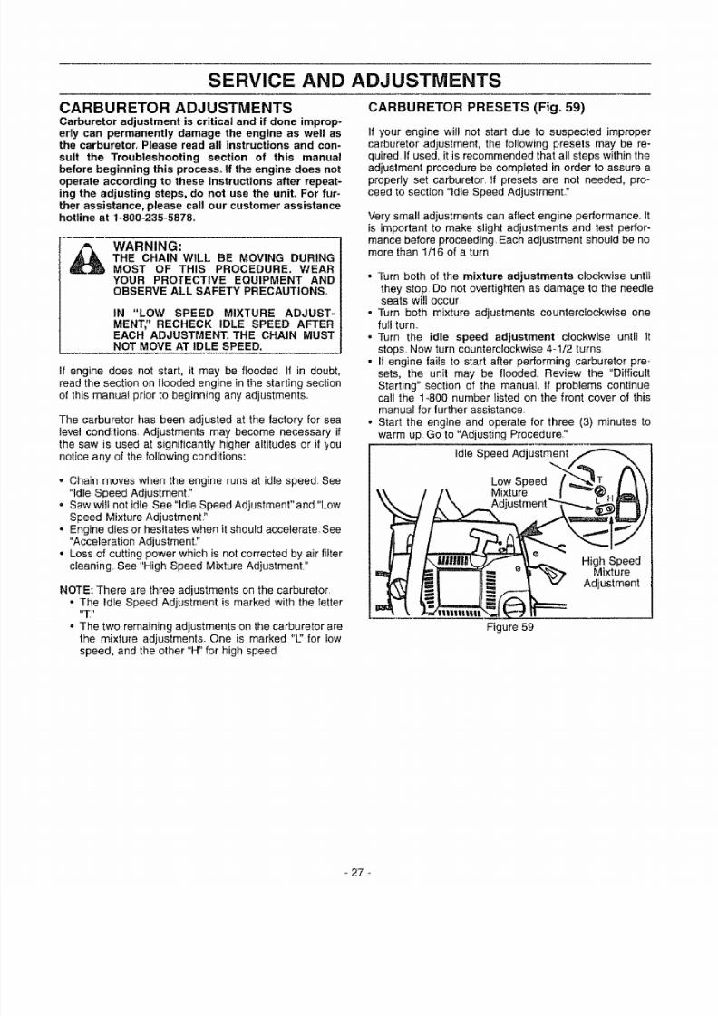
NOTE: There are three adjustments on the carburetor.
• The Idle Speed Adjustment is marked with the letter
• The two remaining adjustments on the carburetor are
the mixture adjustments. One is marked "L:' for low
speed, and the other"H" for high speed
If your engine will not start due to suspected improper
carburetor adjustment, the following presets may be re-quired If used, it is recommended that all steps within the
adjustment procedure be completed in order to assure a
properly set carburetor, if presets are not needed, pro-
ceed to section "Idle Speed Adjustment"
Very small adjustments can affect engine performance. Itis important to make slight adjustments and test perfor-
mance before proceeding. Each adjustment should be nomore than 1/16 of a turn.
• Turn both of the mixture adjustments clockwise until
they stop Do not overtighten as damage to the needleseats wil l occur
• Turn both mixture adjustments counterclockwise onefull turn,
° Turn the idle speed adjustment clockwise until it
stops. Now turn counterclockwise 4-1/2 turns- if engine fails to start after performing carburetor pre-
sets, the unit may be floode& Review the "Difficult
Starting" section of the manual, if problems continuecall the 1_800 number listed on the front cover of this
manual for further assistance
• Start the engine and operate for three (3) minutes to
warm up Go to "Adjusting Procedure,
idle Speed Adjustment
\\ / /\ Mixture l _'_H,_ }
\__i_Adjustment "_l_..,._
_/ i _l_ -'-_._..__ HighSpeed_i __ _'_-"_ .Mixture
_ _ (._ Adjustment
Figure 59
- 27 -

7/27/2019 Chainsaw manual L0707119.pdf
http://slidepdf.com/reader/full/chainsaw-manual-l0707119pdf 28/30
SERVICE AND ADJUSTMENTS
ADJUSTING PROCEDURE HIGH SPEED MIXTURE ADJUSTMENT "H"
IDLE SPEED ADJUSTMENT "T""Aliow the warm engine to idle• Adjust the Idle Speed until the engine continues to run
without stall ing and without the chain moving.- Turn clockwise to increase engine speed if enginestalls or dies.
- Turn counterclockwise to slow engine down and/or to
keep the chain from turning• No further adjustments are necessary if chain does not
move at idle speed and if performance is satisfactory
LOW SPEED MIXTURE ADJUSTMENT "U'
• Allow engine to idle, Turn the Low Speed Mixture Adjustment slowly clock-
wise until the RPM starts to drop. Note the position.
, Turn the Low Speed Mixture Adjustment slowly coum
terclockwise until the RPM speeds up and starts to
drop again. Note the position,. Set the Low Speed Mixture at the midpoint between the
two positions.
IMPORTANT: DO NOT OPERATE ENGINE AT FULLTHROTTLE FOR PROLONGED PERIODS WHILE MAK-
ING HIGH SPEED ADJUSTMENTS AS DAMAGE TO
THE ENGtNE CAN OCCUR.
• Make a test cuL
• Based on performance of the saw while cutting, adjust
the high speed mixture in 1/16 turn increments as fol-lows:
- Clockwise if saw loses power in the cut. Do not adjust
for best power by sound or speed, but judge by how
well the saw performs in the cut.- Counterclockwise ff the saw has speed while out of
the cut, but dies in the cut or lacks power while cut-
ting_
o Repeat the lest cut.° Continue with 1/16 turn adjustmenls until the saw per-
formance is acceptable while cutting• After completing adjustments, check for acceleration°
ACCELERATION CHECK
• If the engine dies or hesitates instead of accelerating,turn the Low Speed Mixture Adjustment 1/16 of a turnat a time counterclockwise until you have smooth accel-eration.
= Check the idle speed for stability and no chain move-
ment. Adjust as necessary..o Recheck for smooth acceleration and stable idle
Repeat process as necessary for acceptable perfor-mance.
28 -

7/27/2019 Chainsaw manual L0707119.pdf
http://slidepdf.com/reader/full/chainsaw-manual-l0707119pdf 29/30
STORAGE
Immediately prepare your unit for storage at the end ofthe season or if it wilt not be used for 30 days or more.
_ ARNING:LLOW THE ENGINE '10 COOL, ANDSECURE THE UNIT BEFORE STORINGOR TRANSPORTING IN A VEHICLE,
STORE UNIT AND FUEL IN AN AREAWHERE FUEL VAPORS CANNOT REACHSPARKS OR OPEN FLAMES FROMWATER HEATERS, ELECTRIC MOTORSOR SWITCHES, FURNACES, ETC.
STORE UNIT WITH ALL GUARDS INPLACE, POSITION SO THAT ANY SHARPOBJECT CANNOT ACCIDENTALLYCAUSE INJURYTO PASSERS BY.
STORE THE UNIT OUT OF THE REACHOF CHILDREN.
WEAR PROTECTIVE GLOVES WHEN
HANDLING CHAIN.THE CHAIN tS SHARPAND CAN CUT YOU EVEN WHEN IT ISNOT MOVING,
GAS CHAIN SAW STORAGE INSTRUCTIONS
If your chain is to be stored for a period of time, clean it
thoroughly prior to storage Remove any dirt, sawdust,
ieaves, oil, grease, etc. Store in a clean dry area.,' Clean the entire unit..
. Clean air filter. Refer to "Customer Responsibilities."
. Inspect the bar clamp area and clean any dirt, sawdust,
grass, or debris that has collected. Inspect the guidebar and chain; replace a guide bar that is bent, warped,
cracked, broken, or damaged in any other way_Replace
a damaged or worn chain.,' Lightly oil external metal surfaces to prevent rust from
forming
o Apply a coating of oil to the entire sudace of the guide
bar and chain; wrap it in heavy paper, or cloth.° Be sure all handles and guards are in place and are
securely fastened. Replace any damaged parts
FUEL SYSTEM
Never use engine or carburetor cleaner products in thefuel tank or permanent damage may occur to fuel systemcomponents Follow these instructions:
o Drain the luel from the unit into an approved fuel con-tainer,
- Drain the fuel lines and carburetor by starting theengine and letting it run until it stops.
,' Allow the engine to cool before storage.
IMPORTANT: It is important to prevent gum depositsfrom forming in essential fuel system parts such as the
carburetor, fuel filter, fue! hose or tank during storageAlso, experience indicates that alcohol blended fuels,
those that use ethanol or methanol (called gasohol oroxygenaled fuel), can attract moisture and form acidic
gas which will damage your engine .To avoid engine prob-lems, the fuel system should be emptied before storageof 30 days or longer.
Fuel stabilizer is an acceptable alternative in minimizingthe formation of fuel gum deposits during storage. Add
stabilizer to the gasoline in the fuel tank or fuel storage
container Always follow the mix instructions found on sta-
bilizer containers Run engine at least 5 minutes afteradding stabilizer to allow the stabilizer to reach the car-buretor
CRAFTSMAN 40:1 2-cycle engine oi! (AIR-COOLED) is
specially blended with fuel stabilizer If you do not use this
Sears oil, you can add a fuel stabilizer to your fuel tank.
INTERNAL ENGINE
= Remove spark plug and pour 1 teaspoon of 40:! 2-
cycle engine oil (AIR-COOLED) through the spark plug
opening. Slowly pull the starter rope 8 to 10 times to
distribute oil to inner engine surfaces.
. Replace spark plug wilh a new one of the recommend-
ed type and heat range. Refer to "Product Specifica-tions."
• Clean air filter Refer to "Customer Responsibil it ies.."
° Re-install all covers and hardware removed for access;tighten all screws and fasteners.
,, Check entire unit for loose screws, nuts, and bolts.
Replace any damaged, broken, or worn parts.- Lightly oil external metal surface to prevent rust from
forming.
• Use fresh fuel having the proper gasoline to oil ratio at
the beginning of the next season.
OTHER
- Do not store gasoline from one season to another.
o Replace your gasoline can if your can starts to rusL Rust
and/or dirt in your fuel system wilt cause problems.
* Store your unit in a well ventilated area and covered, ifpossible, to prevent dust and dirt accumulation Do not
cover with plastic. Plastic cannot breathe and willinduce condensation and eventual rust or corrosion
IMPORTANT: NEVER COVER UNIT WHILE ENGINE
AND EXHAUST AREAS ARE STILL WARM
- 29 -

7/27/2019 Chainsaw manual L0707119.pdf
http://slidepdf.com/reader/full/chainsaw-manual-l0707119pdf 30/30
TROUBLE SHOOTING POINTS
TROUBLE SHOOTING CHART
SYMPTOM
Engine will not start
or wilt run only fora few seconds
after starting.
Engine will not idle
properly
Engine wil l notaccelerate, lacks
power, or diesunder a load.
Engine smokes
excessively
Engine runs hot°
Oil inadequate for bar
and chain lubrication.,
Chain moves at
idle speed.
Chain does not move
when engine isaccelerated.
Chain clatters or
cuts roughly
CAUSE
I Fuel tank empty.
2. Engine flooded.
3. Spark plug not firing.
4, Fue! not reaching carburetor,5. Carburetor requires adjustment.,
6. Stop switch off7o None of the above.
1. Idle speed set too fast or too slow.
2_ Low speed mixture requires adjuslment3. Crankshaft seals worn.
4, Compression low5. None of the above.
1. Air filter dirty,
2. Spark plug fouled
3. Carburetor requires adjustment_
4. Exhaust ports or muffler outlets plugged
5 Compression low.
6. None of the above.,1_Air filter dirty,2, Fuel mixture incorrect,
3. High speed mixture requires adjustment
4. Choke partially on
1, Fuel mixture incorrect.
2., High speed mixture set too low (Lean),
3. Spark plug incorrect.
4 Exhaust ports or muffler outlets plugged r
5. Carbon build-up on muffler outlet screen.6, Fan housing/cylinder fins dirty.,7. None of the above.
t. Oil tank empty.
2,, Oil pump or oil filter clogged3. Guide bar oi! hole blocked,
1. Idle speed requires adjustment
2. Clutch requires repair
1. Chain tension too tight.
2, Carburetor requires adjustment,
3. Guide bar rails pinched.4. Clutch slipping
1., Chain tension incorrect.
2. Cutters damaged,3, Chain worn.
4 Cutters dull, improperly sharpened, or
depth gauges too high,
CORRECTION
1. Fil l tank with correct fuel mixture
2 See "Starting Instructions."
3. Install new plug/check ignitionswitch
4. Replace fuel filter; inspect fuel tine5, See "Carburetor Adjustments."
6. Move switch to the "START" position.
7, Contact your Sears Service CentedDept
!. See "Carburetor Adjustments"
2, See "Carburetor Adjustments."
3 Contact your Sears Service Center/Dept_
4. Contact your Sears Service Center/Dept.
5, Contact your Sears Service Center/Dept.
t. Clean or replace air filter.2_ Clean or replace spark plug and re-gap.
3 See "Carburetor Adjustments._'
4. Contact your Sears Service CentedDepto
5. Contact your Sears Service Center/DepL
6. Contact your Sears Service Center/Dept,1. Clean or replace air filler.2, Refuel with correct fuel mixture.
3. See "Carburetor Adjustments."4 Push choke knob in.
!.
2.
3.4.
5.
6.
7-
I
2,3.
1,
2.
3,
4,
g,
4_
See "Fueling Your Unit?
See "Carburetor Adjustments?
Replace with correct plug.
Contact your Sears Service Center/Dept.
Clean spark arrestor screenClean area.
Contact your Sears Service CentedDept,
Fill oil tank
Contact your Sears Service Center/Dept.Remove bar and clean.
See "Carburetor Adjustments.._'
Contact your Sears Service Center/Dept.
See "Chain Tension;'
See "Carburetor Adjustments."
Repair or replace.
Contact your Sears Service Center/Dept.
See "Chain Tension"
Contact your Sears Service Center/Dept
Resharpen or replace chain
Have chain sharpened
5. Sprocket worn. 5. Contact your Sears Service Center/Dept
6 Chain installed backwards. 6 Install chain in right direction.
Chain stops within 1.'Chain cutter tops not filed flat.r 1 Have chain sharpened
the cut. 2 Guide bar burred or bent; rails uneven. 2. Repair or replace guide bar.3. Clutch slipping 3. Contact your Sears Service CenteriDepL
Chain cuts at an 1. Cutters damaged on one side. 1. Have chain sharpened
angle, 2. Chain dull on one side. 2, Have chain sharpened
3. Guide bar bent or worn. 3. Replace guide bar,
If situatiohs occur which are not covered in this manua use care and good judgement