challenges in material development for pemfcweb.iitd.ac.in/~sbasu/seminar/presentation/16dr....
TRANSCRIPT
Dec.1-2,2006 National Symposium, IITD, 1-2 Dec 2006FC-Seminar IIT-D
1
Challenges in Material Development for PEMFC
N.RajalakshmiPresented by
K S Dhathathreyan
Centre for Fuel cell TechnologyARC-International (ARCI)
120, Mambakkam Main RoadMedavakkam, Chennai
at theNational Seminar on Challenges in Fuel Cell Technology: India’s
PerspectiveDec. 1- 2,2006, New Delhi, India
Dec.1-2,2006 National Symposium, IITD, 1-2 Dec 2006FC-Seminar IIT-D
2
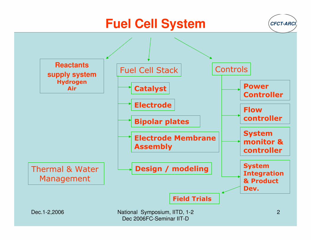
Fuel Cell System
Fuel Cell Stack Controls
Power Controller
Flow controller
System monitor & controller
System Integration
& Product Dev.
Reactants
supply systemHydrogen
Air
Thermal & Water Management
Catalyst
Bipolar plates
Electrode MembraneAssembly
Electrode
Design / modeling
Field Trials
CFCT-ARCI
Dec.1-2,2006 National Symposium, IITD, 1-2 Dec 2006FC-Seminar IIT-D
3
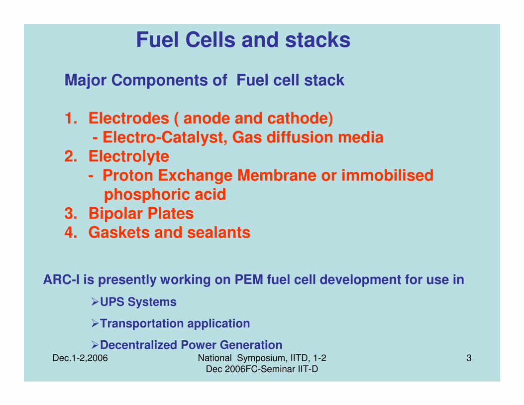
Major Components of Fuel cell stack
1. Electrodes ( anode and cathode) - Electro-Catalyst, Gas diffusion media
2. Electrolyte - Proton Exchange Membrane or immobilised
phosphoric acid 3. Bipolar Plates 4. Gaskets and sealants
Fuel Cells and stacks
ARC-I is presently working on PEM fuel cell development for use in
�UPS Systems
�Transportation application
�Decentralized Power Generation
Dec.1-2,2006 National Symposium, IITD, 1-2 Dec 2006FC-Seminar IIT-D
4
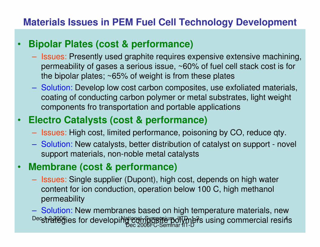
• Bipolar Plates (cost & performance)
– Issues: Presently used graphite requires expensive extensive machining,permeability of gases a serious issue, ~60% of fuel cell stack cost is for the bipolar plates; ~65% of weight is from these plates
– Solution: Develop low cost carbon composites, use exfoliated materials, coating of conducting carbon polymer or metal substrates, light weight components fro transportation and portable applications
• Electro Catalysts (cost & performance)
– Issues: High cost, limited performance, poisoning by CO, reduce qty.
– Solution: New catalysts, better distribution of catalyst on support - novel support materials, non-noble metal catalysts
• Membrane (cost & performance)
– Issues: Single supplier (Dupont), high cost, depends on high water content for ion conduction, operation below 100 C, high methanolpermeability
– Solution: New membranes based on high temperature materials, new strategies for developing composite polymers using commercial resins
Materials Issues in PEM Fuel Cell Technology Development

Dec.1-2,2006 National Symposium, IITD, 1-2 Dec 2006FC-Seminar IIT-D
5
ARC-I is addressing some of these material issues:
1. Development of low cost and low weight bipolar plates
2. Development of Non Noble Metal catalysts
3. Low cost membrane

Dec.1-2,2006 National Symposium, IITD, 1-2 Dec 2006FC-Seminar IIT-D
6
Tungsten carbide(WC) for PEMFC
1. WC has catalytic properties similar to Platinum-like noble metals.
2. Pt-like behavior was due to donation of e- from carbon to the 5d band of
W, resulting in an electronic structure similar to that of Pt.
3. WC plays an important role as an anode catalyst when reformate H2 fuel is
used.
The differences in catalytic activities of tungsten carbide result from the differences in
surface properties, particle morphology and chemical composition of the surface layer than that of the bulk.
Particle morphology has a strong influence on electrocatalytic properties of tungsten carbide catalysts.
Adjusting the particle morphology is an efficacious way to control its catalytic activity
Extensive attention is required to prepare tungsten carbide catalysts.
Dec.1-2,2006 National Symposium, IITD, 1-2 Dec 2006FC-Seminar IIT-D
7
For high surface area samples the following parameters need to be optimized
•the space velocity of the synthesis gas, •the precursors, •the ratio of the composite in the mixture gas, •pressure and temperature.
Different methods of synthesis
1, Intermittent Microwave Heating --- relatively simple and rapid --- But
no electrocatalytic activity ---- only composite tungsten carbide nanocrystalpromoted Platinum on carbon is active
2. Chemically reduced mechanical alloying of tungsten oxide, magnesium and carbon by ball milling for 2 days, involves many steps like removal of by product, washing, rinsing and drying. The method is time consuming and energy intensive and not suitable for scaling up.
3. Hydrocarbon cracking of oxide powders at 600-1400C for 2h. The final product contains pure tungsten in addition to the carbide, which requires additional carbon and carburisation. Hence this process is inefficient and not amenable for large scale production.

Dec.1-2,2006 National Symposium, IITD, 1-2 Dec 2006FC-Seminar IIT-D
8
CFCT/ARCI Objective is •to develop a simple cost effective process to synthesize nano WC powders.•to replace the expensive Pt by the non noble metals in PEMFC•to identify the exact composition of tungsten carbide for improved catalytic activity.
Advantages of present method developed at ARCI
1. An improved two step process from precursors which are readily soluble in water and cost effective.
2. The composition of Nano WC can be controlled by varying the ratio of precursors
3. The sample is free of oxides
4. Particle morphology can be controlled from 60 – 80 nm.
5. Catalytic activity of the nanotungsten carbide can be improved by engineering the composition of nano WC.
Dec.1-2,2006 National Symposium, IITD, 1-2 Dec 2006FC-Seminar IIT-D
9
The Tungsten carbide powders developed at ARCI have been successfully used as anode catalyst in PEM Fuel cell.
Use of tungsten carbide as catalyst support is also beinginvestigated
Studies on ORR with tungsten carbide isunder progress..

Dec.1-2,2006 National Symposium, IITD, 1-2 Dec 2006FC-Seminar IIT-D
10
Organic-Inorganic Composite polymeric membrane for fuel cell humidification
PEMFC performance is strongly governed by conductance of the membrane electrolyte.
- Membrane (Nafion)conductance is strongly dependent on its hydration state ( Higher the hydration state – better is the conductivity)
Reactant gases have to be humidified to prevent membrane from drying out.
One of the methods of humidification is through the use of membranes
Dec.1-2,2006 National Symposium, IITD, 1-2 Dec 2006FC-Seminar IIT-D
11
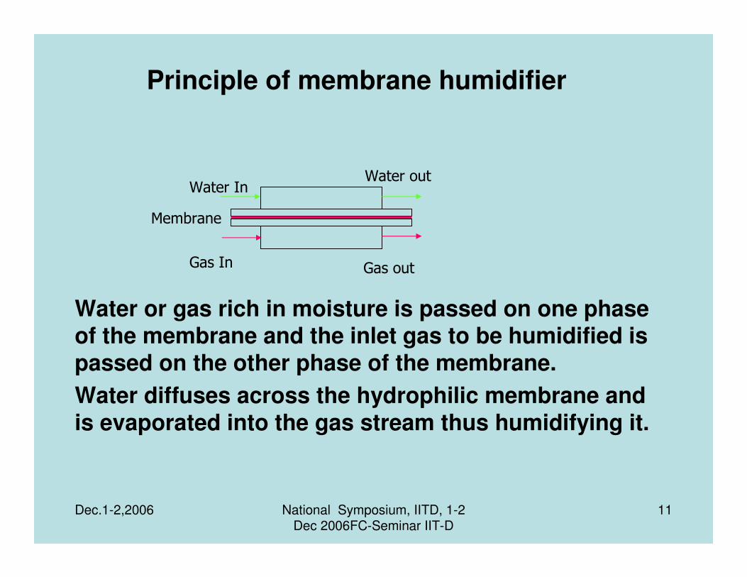
Principle of membrane humidifier
Water or gas rich in moisture is passed on one phase of the membrane and the inlet gas to be humidified is passed on the other phase of the membrane.
Water diffuses across the hydrophilic membrane and is evaporated into the gas stream thus humidifying it.
Water InWater out
Gas In Gas out
Membrane

Dec.1-2,2006 National Symposium, IITD, 1-2 Dec 2006FC-Seminar IIT-D
12
Membranes used for humidification
Polymeric materials satisfying the following properties can be used for membrane humidification
- High water transport property across the membrane
-All ion exchange and hydrophilic polymers satisfy this
condition
- Sufficient strength to withstand the pressure across the membrane
due to water/ gas rich in moisture and gas to be humidified onthe
other side.
Most commonly used materials include
1. Nafion or other perfluorosulphonic acid membrane.
Cost of these materials are prohibiting
2.Composite materials in which polymer is filled with
hydrophilic materials- High loadings of the hydrophilic filler
material would be required and such films would lack

Dec.1-2,2006 National Symposium, IITD, 1-2 Dec 2006FC-Seminar IIT-D
13
ARCI I (CFCT) HAS DEVELOPED A LOW COST MEMBARNE & A HUMIDIFIER
The process and the design have been patented.
Dec.1-2,2006 National Symposium, IITD, 1-2 Dec 2006FC-Seminar IIT-D
14
Advantages of the CFCT-ARCI membrane humidifier
1. Parasitic power losses( power required for heating water, evaporation etc.) are reduced .
2. These humidifiers can be integrated into the fuel cell stack so that the temperature of the stack and the humidifier are the same.
3. It does not lead to flooding of the gases.
Dec.1-2,2006 National Symposium, IITD, 1-2 Dec 2006FC-Seminar IIT-D
15
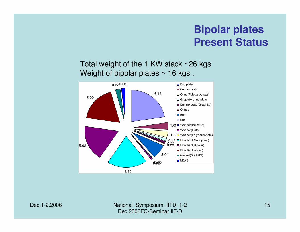
6.13
1.00
0.79
0.450.220.02
2.04
0.050.030.090.02
5.30
5.02
5.00
0.620.53 End plate
Copper plate
Oring(Polycarbonate)
Graphite oring plate
Dummy plate(Graphite)
Orings
Bolt
Nut
Washer(Beleville)
Washer(Plate)
Washer(Polycarbonate)
Flow field(Monopolar)
Flow field(Bipolar)
Flow field(w ater)
Gasket(0.2 FRG)
MEAS
Total weight of the 1 KW stack ~26 kgsWeight of bipolar plates ~ 16 kgs .
Bipolar platesPresent Status
Dec.1-2,2006 National Symposium, IITD, 1-2 Dec 2006FC-Seminar IIT-D
16
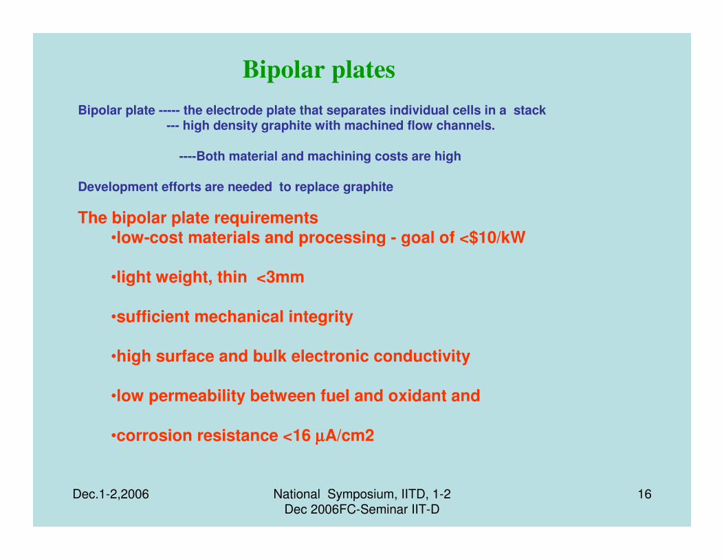
Bipolar plate ----- the electrode plate that separates individual cells in a stack--- high density graphite with machined flow channels.
----Both material and machining costs are high
Development efforts are needed to replace graphite
The bipolar plate requirements •low-cost materials and processing - goal of <$10/kW
•light weight, thin <3mm
•sufficient mechanical integrity
•high surface and bulk electronic conductivity
•low permeability between fuel and oxidant and
•corrosion resistance <16 µµµµA/cm2
Bipolar plates

Dec.1-2,2006 National Symposium, IITD, 1-2 Dec 2006FC-Seminar IIT-D
17
Choice of material is important to the performance and lifetime of the PEM fuel cell stack.
A range of bipolar plate materials exist including• Composites ( carbon-Carbon, carbon-
polymer),• Titanium and TiN• Aluminum, and• Stainless Steel
The material of choice will depend upon the driving constraints of the application, e.g. Mass market, military, space, stationary power
Bipolar plates
Dec.1-2,2006 National Symposium, IITD, 1-2 Dec 2006FC-Seminar IIT-D
18
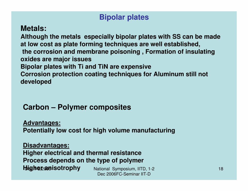
Metals:Although the metals especially bipolar plates with SS can be made at low cost as plate forming techniques are well established,the corrosion and membrane poisoning , Formation of insulating oxides are major issues Bipolar plates with Ti and TiN are expensiveCorrosion protection coating techniques for Aluminum still not developed
Carbon – Polymer composites
Advantages:Potentially low cost for high volume manufacturing
Disadvantages:Higher electrical and thermal resistanceProcess depends on the type of polymerHigher anisotrophy
Bipolar plates
Dec.1-2,2006 National Symposium, IITD, 1-2 Dec 2006FC-Seminar IIT-D
19
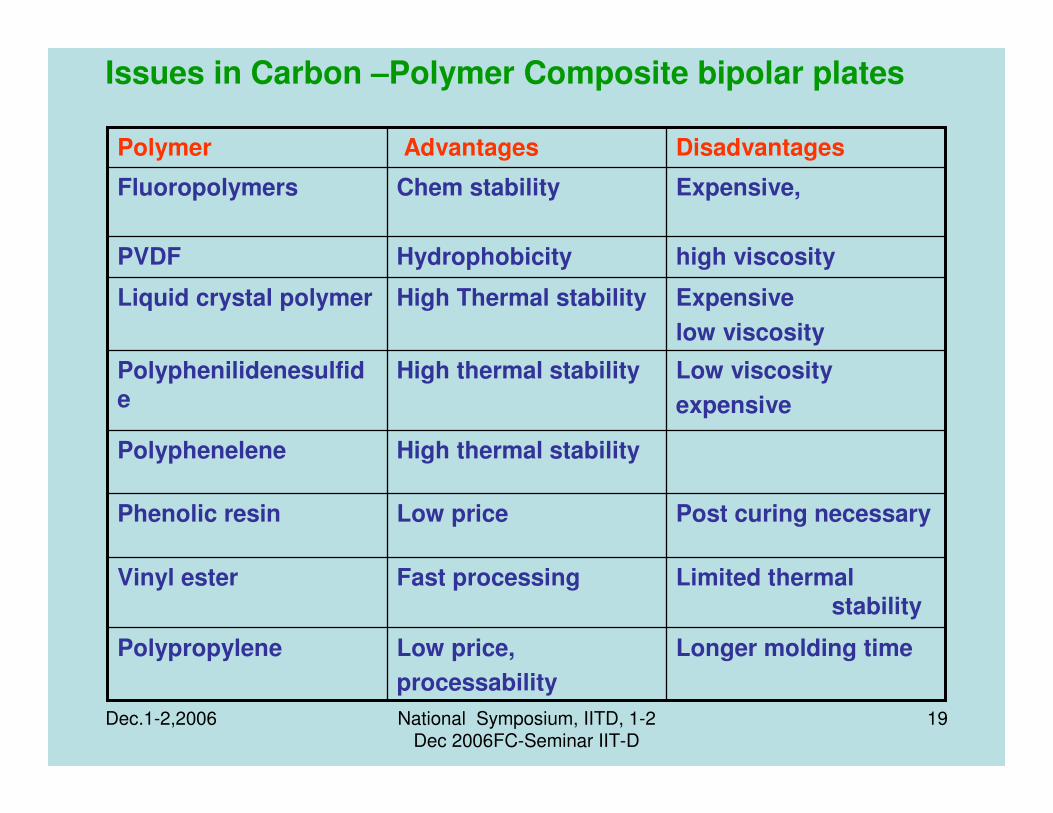
Issues in Carbon –Polymer Composite bipolar plates
Limited thermal stability
Fast processingVinyl ester
Post curing necessaryLow pricePhenolic resin
High thermal stabilityPolyphenelene
Expensive
low viscosity
High Thermal stabilityLiquid crystal polymer
Low viscosity
expensive
High thermal stability Polyphenilidenesulfide
Longer molding timeLow price,
processability
Polypropylene
high viscosityHydrophobicityPVDF
Expensive, Chem stabilityFluoropolymers
DisadvantagesAdvantages Polymer

Dec.1-2,2006 National Symposium, IITD, 1-2 Dec 2006FC-Seminar IIT-D
20
ARC-I has developed a technology for making Exfoliated Graphite ( EFG) and the technology has been transferred
Gasket materials made from EFG are already used in
many applications e.g., gaskets
EFG can be used to make bipolar plates suitable for Fuel cells
ARCI (CFCT) has developed a technology for making bipolar plates( various designs) using EFG which have been successfully used in developing fuel cell stacks of various capacities
The process has been patented
Dec.1-2,2006 National Symposium, IITD, 1-2 Dec 2006FC-Seminar IIT-D
21
Advantages of using Exfoliated Graphite (EFG)
plates
• Light weight
• No machining required
• Easy Manufacturability
• Amenable for Large scale production
• Time conserving
• Easy to assemble and disassemble in a stack
• Flow field designs can be embossed
• No cutting to the desired siz- No loss of material
• Die size determine the area of the plate

Dec.1-2,2006 National Symposium, IITD, 1-2 Dec 2006FC-Seminar IIT-D
22
Low Cost bipolar plates 300-400 sq.cm

Dec.1-2,2006 National Symposium, IITD, 1-2 Dec 2006FC-Seminar IIT-D
23
Factors Influencing PEMFC Performance
TRACK
AIR/O2
FLOW
GDL INTRUSION,
BRIDGING
LENGTH
PRESSURE DROP
ALONG TRACK
EVEN O2
DISTRIBUTION
MAXIMISE CONTACT
AREA FOR
CONDUCTIVITY
MINIMISE CONTACT
AREA FOR FLUID
TRANSFER
REACTION PROD.
REMOVAL
O2 DELIVERY
IN z-DIRECTION
EASE OF
FABRICATION –
DESIGN
LIMITATIONS
CONDENSED
WATER REJECTION
LAND
GDLPEM
CFCT-ARCI
Dec.1-2,2006 National Symposium, IITD, 1-2 Dec 2006FC-Seminar IIT-D
24
• FC systems are complex entities.
•The complexity is hidden in the microscopic details , mostly inaccessible to the experimental “eye”.
•More specifically , FC operation entails circulation of protons, electrons, reactants and water , with the processes in the structural
elements of the cell coupled strongly and non linearly to each
other.
•The fundamental difficulties associated with FC design stem from this
non linear coupling.
Herein lies a Challenge!
CFCT-ARCI
Dec.1-2,2006 National Symposium, IITD, 1-2 Dec 2006FC-Seminar IIT-D
25
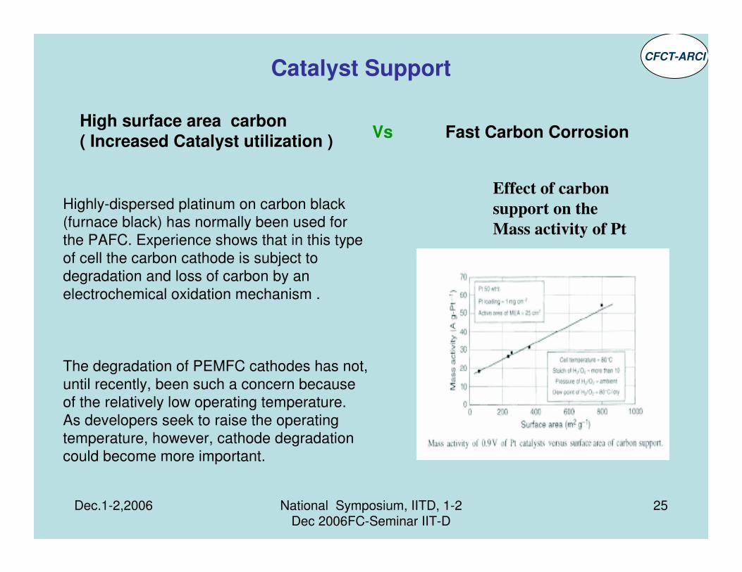
Effect of carbon
support on the
Mass activity of Pt
Catalyst Support
Highly-dispersed platinum on carbon black
(furnace black) has normally been used for
the PAFC. Experience shows that in this type
of cell the carbon cathode is subject to
degradation and loss of carbon by an
electrochemical oxidation mechanism .
The degradation of PEMFC cathodes has not,
until recently, been such a concern because
of the relatively low operating temperature.
As developers seek to raise the operating
temperature, however, cathode degradation
could become more important.
High surface area carbon ( Increased Catalyst utilization )
Fast Carbon CorrosionVs
CFCT-ARCI
Dec.1-2,2006 National Symposium, IITD, 1-2 Dec 2006FC-Seminar IIT-D
26
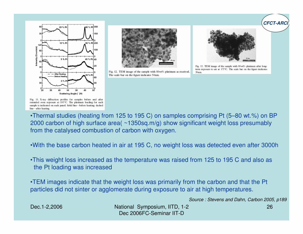
•Thermal studies (heating from 125 to 195 C) on samples comprising Pt (5–80 wt.%) on BP
2000 carbon of high surface area( ~1350sq.m/g) show significant weight loss presumably
from the catalysed combustion of carbon with oxygen.
•With the base carbon heated in air at 195 C, no weight loss was detected even after 3000h
•This weight loss increased as the temperature was raised from 125 to 195 C and also as
the Pt loading was increased
•TEM images indicate that the weight loss was primarily from the carbon and that the Pt
particles did not sinter or agglomerate during exposure to air at high temperatures.
Source : Stevens and Dahn, Carbon 2005, p189
CFCT-ARCI
Dec.1-2,2006 National Symposium, IITD, 1-2 Dec 2006FC-Seminar IIT-D
27
Nano catalysts have high surface area and perform better
The question is the how to translate the good performance showed by the nano catalysts in electrochemical studies ( half cell) into single cell and eventually to the stack.The issue here is how to retain the activity of the catalyst with out its sintering
Catalyst CFCT-ARCI

Dec.1-2,2006 National Symposium, IITD, 1-2 Dec 2006FC-Seminar IIT-D
28
TEM micrographs of catalyst particle growth after FC operation
Test conditions: 100C, H2/.O2 1.25/5,Pressure ambient,Dew point 100C, CD 1.5 A/sq cm
CFCT-ARCI
Dec.1-2,2006 National Symposium, IITD, 1-2 Dec 2006FC-Seminar IIT-D
29
The Catalyst layer
At the catalyst layer, the following reactions occur
•Reactant diffusion,
•Electron and proton migration, and
•Charge-transfer kinetics
• The presence of liquid water complicates further.
•Thickness, composition and pore-space morphology control the transport and reaction.
•The size distributions and wetting properties of pores control water and heat exchange
•Hydrophilic micropores are good for evaporation
•Hydrophobic mesopores are good for gas transport.
For optimal catalyst utilization, water management and the overall successful performance of the cell, understanding the rules of this competition is difficult
Dec.1-2,2006 National Symposium, IITD, 1-2 Dec 2006FC-Seminar IIT-D
30
•Local capillary equilibrium between the liquid and gas phase should exist in the micropores (1–10 nm) favouringlarge evaporation rates
•Mesopores (10–40 nm) should be open for gaseous transport of reactants and products.
•The two major functions – evaporation and gaseous transport are controlled by Part of Micro- and Mesopores, and their respective wetting properties,
Role of Catalyst Layers

Dec.1-2,2006 National Symposium, IITD, 1-2 Dec 2006FC-Seminar IIT-D
31
Pt activity in conventional CLs reaches at most 10–20 % of its full potential
•Most of the expensive Pt is utilized ineffectively
•CLs need to be made much better and much cheaper.
•Composition and thickness need to be readily adjusted
Getting 100% utilisation, requires more innovative fabrication procedures – electrochemical deposition of Pt at this boundary.
Difficult to estimate how much effort should be invested in such procedures, but their prospects for optimized catalyst utilization are clear.
The issues of Catalyst/catalyst layers

Dec.1-2,2006 National Symposium, IITD, 1-2 Dec 2006FC-Seminar IIT-D
32
Two key measures of CL performance:
•catalyst utilization
•catalyst effectiveness.
Catalyst utilisation in ideal three-phase composites:
•Catalyst particles at the intersections of the Pt/C phase,
•Gas pores - connected with the GDL and
•Ionomer phase - connected with the membrane
Catalyst effectiveness is ,
•varying concentrations and
•reaction rates with performance.
Dec.1-2,2006 National Symposium, IITD, 1-2 Dec 2006FC-Seminar IIT-D
33
•CL’s are the best the source of any water management problems in FCs.
•PEFCs need a medium that converts huge amounts of liquid water arriving in the CL into vapour.
•Once liquid water arrives in GDLs or FFs, they are unable to handle it.
•The CL is the PEFC’s favourite water exchanger.
•High rates of evaporation effectively convert the waste heat of the reaction into latent heat of vapour
•Effective operation of CLs in terms of FC water balance is closely linked to their porous structure.
Role of Catalyst Layers

Dec.1-2,2006 National Symposium, IITD, 1-2 Dec 2006FC-Seminar IIT-D
34
The thrust in R&D has been towards reducing the catalyst amount and developing CO tolerant catalysts. The progress is impressive
Binary and ternary catalysts have been tested especially for DMFC
But
For performance improvement equal if not more thrust should have been on developing high performance cathode catalysts (and catalyst
layer) as its function determines the oxygen reduction kinetics which in turn determines the cell performance.
Pt-Co/Cr/Sn have been reported to improve the ORR
Catalyst & Catalyst layers
The challenge is to develop low cost highly stable
oxygen reduction catalysts
CFCT-ARCI
Dec.1-2,2006 National Symposium, IITD, 1-2 Dec 2006FC-Seminar IIT-D
35
The electrode is a complex subject with a number of simultaneous reactions
taking place in its structure.
The electrode structure among other things determines the the percentage utilization of the catalyst which is a major issue
The Fuel Cell Electrode
Understanding the rules of this competition is crucial for optimal catalystutilization, water management and the overall successful performance of the cell.
CFCT-ARCI
Dec.1-2,2006 National Symposium, IITD, 1-2 Dec 2006FC-Seminar IIT-D
36
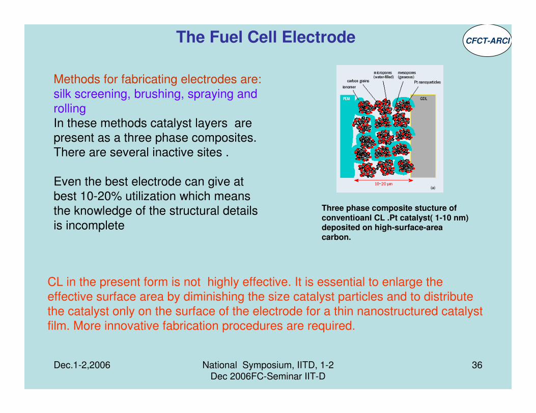
Three phase composite stucture of conventioanl CL .Pt catalyst( 1-10 nm) deposited on high-surface-area carbon.
Methods for fabricating electrodes are:
silk screening, brushing, spraying and
rollingIn these methods catalyst layers are present as a three phase composites.
There are several inactive sites .
Even the best electrode can give at
best 10-20% utilization which means
the knowledge of the structural details
is incomplete
The Fuel Cell Electrode CFCT-ARCI
CL in the present form is not highly effective. It is essential to enlarge the
effective surface area by diminishing the size catalyst particles and to distribute
the catalyst only on the surface of the electrode for a thin nanostructured catalyst film. More innovative fabrication procedures are required.
Dec.1-2,2006 National Symposium, IITD, 1-2 Dec 2006FC-Seminar IIT-D
37
Site selective Electro deposition of Pt on a substrate at the boundary should form the electronically conductive phase
• make CLs of extremely thin two-phase composites (~100–200 nm thick) with the catalyst deposited site specifically
The remaining volume filled with liquid water as the medium for proton and reactant transport.
Since impregnation with ionomer is not used in this method
• the protonic contact resistance at the PEM/CL interface can be mitigated
• CL insensitive to the type of PEM.
• This could result in 100% Pt utilization
While making such an electrode on a small scale may be possible, large scale production would be a challenge
Alternative catalyst layerCFCT-ARCI
Dec.1-2,2006 National Symposium, IITD, 1-2 Dec 2006FC-Seminar IIT-D
38
Nanostructured MEA
In the conventional method, it is very difficult to control the nanostructure due to conc. catalyst ink and heat press process.
ARCI is looking at developing Electrophoretic deposition and pulsed electro-depostion techniques which offer many advantages

Dec.1-2,2006 National Symposium, IITD, 1-2 Dec 2006FC-Seminar IIT-D
39
Membrane Electrolyte
Present status of commercial Membranes
• Dupont has been supplying Nafion series of membranes for over two decades
• Initially used thicker membrane was slowly changed to thinner membranes with
improved performance
• Durability and degradation have become big issue and Dupont supplies only a chemically stabilised membrane which is yet to be tested in full scale.
• This new development is going to affect the progress in developing PEMFC especially in labs where Dupont membrane is used in the absence of other
suppliers
CFCT-ARCI

Dec.1-2,2006 National Symposium, IITD, 1-2 Dec 2006FC-Seminar IIT-D
40
Membrane ElectrolyteCFCT-ARCI

Dec.1-2,2006 National Symposium, IITD, 1-2 Dec 2006FC-Seminar IIT-D
41
“For practical use,” it is crucial to develop PEMs of high conductivity under
low humidity (0–50%) at high temperatures (100–200ºC).”
Two key approaches are being investigated in this regard.
1. To increase the water-holding ability of the Nafion (or similar)
membrane at temperatures greater than 100 ºC by doping
the membrane with inorganic materials.
2. Replace Nafion-like membranes and to exploit alternativechemical species for proton conduction.
Until now, scientists have had some limited success pursuing theNafion-replacement strategy with systems such as PBI-H3PO4 and
imidazole where H3PO4 and imidazole are the respective proton
conductors.
On the plus side, these systems enable Fuel Cells to operate at
temperatures above 100 ºC.
The downside is the propensity of small molecules like H3PO4 to
leak out with water, and the poor conductivity and electrochemical stability of imidazole.
CFCT-ARCI
Dec.1-2,2006 National Symposium, IITD, 1-2 Dec 2006FC-Seminar IIT-D
42
Membrane Electrode Assembly
The membrane and the catalyst layers are bonded together to form
the MEAs. – zero gap assembly
The present fabrication procedures hardly reveal any degree
of precision and there is considerable scope for
improvement
The major challenge is to develop methods which are suitable
for bulk production
CFCT-ARCI

Dec.1-2,2006 National Symposium, IITD, 1-2 Dec 2006FC-Seminar IIT-D
43
Bipolar plate ----- the electrode plate that separates individual cells in a stack--- high density graphite with machined flow channels.
----Both material and machining costs are high
Continuous R&D has resulted in developing bipolar plates which most of the following requirements
•light weight, thin <3mm
•sufficient mechanical integrity
•high surface and bulk electronic conductivity
•low permeability between fuel and oxidant and
•corrosion resistance <16 mA/cm2
Bipolar plates
The Challenge is to covert this knowledge into manufacturing to reach the goal of <$10/kW
CFCT-ARCI

Dec.1-2,2006 National Symposium, IITD, 1-2 Dec 2006FC-Seminar IIT-D
44
FC system must be designed as a whole, not as a collection of stand-alone parts . A FC is like a living organism : malfunctioning of one organ is likely to destroy the whole body
FC design can therefore be thought of as optimization problem . The merit function in this optimization process being the power density obtained at given cost, weight and life time.
This merit function is the focal point for the technology push
Effect of operating voltage
0.4V
0.8V
CFCT-ARCI
Dec.1-2,2006 National Symposium, IITD, 1-2 Dec 2006FC-Seminar IIT-D
45
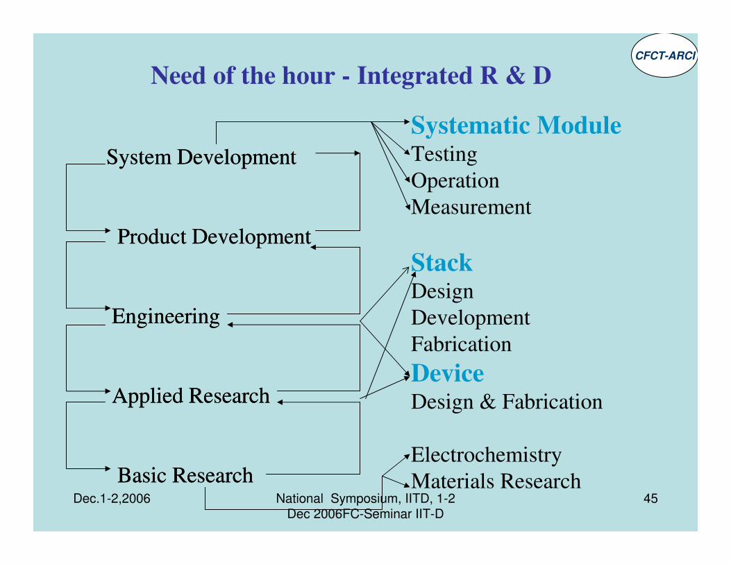
System Development
Product Development
Engineering
Applied Research
Basic Research
System Development
Product Development
Engineering
Applied Research
Basic Research
Need of the hour - Integrated R & D
Systematic ModuleTesting
Operation
Measurement
Stack Design
Development
Fabrication
DeviceDesign & Fabrication
Electrochemistry
Materials Research
CFCT-ARCI
Dec.1-2,2006 National Symposium, IITD, 1-2 Dec 2006FC-Seminar IIT-D
46
Rating of Improvements in Fuel Cell technology- Some commonly agreed measures for system efficiency are
power density, dynamic behavior, durability
This requires a harmonized testing procedures both for entire Fuel Cell systems
and for system components under a variety of boundary conditions
e.g. Different applications
Different stack concepts
Type of fuels and quality
Till recently no standardized test procedures for Fuel Cells, stacks, and systems existed.
The same applies for their assessment against user requirements in the stationary, transport
and portable applications.
In practice, many laboratories and manufacturers have developed their own test protocols to
meet their needs and those of their customers showing clearly the need for harmonisation of
testing procedures and measurement methods to ensure a smooth introduction of the
technology and to provide equal opportunities of the market operators and a decent and
confident comparison basis for the customers.
US Fuel cell council has announced a trial protocol for testing single cells and stacks
FTSTEP is another attempt in EU
StandardsCFCT-ARCI