change chg 1 · expands ca leg application. e. chapter 7. f. chapter 8. numerous editorial changes...
TRANSCRIPT

Distribution: A-W(PO/AR/AS/AT/FS)-3; AJR-32 (15 Cys); AJW-32 (200 Cys); AJR-33 (10 Cys); AJW-352 (15 Cys); AOS-200 (5 Cys); AMA-200 (12 Cys); A-X(FS/AT/AS)-3; A-FAF-0 (STD); AEU-1 (10 Cys); A-FFS-0 (STD); ZVN-826; Special Military and Public Addresses
Initiated By: AFS-420
CHANGE U.S. DEPARTMENT OF TRANSPORTATION FEDERAL AVIATION ADMINISTRATION
8260.19D CHG 1
National Policy
Effective Date: 07/11/2008
SUBJ: Flight Procedures and Airspace 1. PURPOSE. This order provides guidance to all FAA personnel for the administration and accomplishment of the FAA Flight Procedures and Airspace Program. 2. DISTRIBUTION. This order is distributed in Washington headquarters to the branch level in the Offices of Aviation Policy and Plans, Aviation Research, Airport Safety and Standards, the Air Traffic Organization (Safety, En Route and Oceanic Services, Terminal Services, System Operations Services, and Technical Operations Services), and Flight Standards Service; to the Aeronautical Information Management Group (AJR-32), the National Flight Procedures Office (AJW-32), Airspace and Rules Group (AJR-33), the National Aeronautical Charting Office (AJW-352), and the National Airway Systems Engineering Group (AOS-200); to the Regulatory Standards Division; to the branch level in the regional Flight Standards and Airports Divisions; to the Air Traffic and Technical Operations Service Areas, to all Flight Inspection Field Offices; to the Europe, Africa, and Middle East Area Office (AEU-1); to all Flight Standards Field Offices; Special Mailing List ZVN-826; and Special Military and Public Addressees. 3. EFFECTIVE DATE. July 31, 2008 4. EXPLANATION OF CHANGES. Significant areas of new direction, guidance, policy, and criteria as follows: a. TABLE OF CONTENTS. Updates Table of Contents to coincide with the pages changed. b. CHAPTER 2. (1) Section 4. Updates policy on processing Expanded Service Volume (ESV) requests. (2) Section 5. Revises policy on implementing Epoch Year Magnetic Variation for the United States Air Force (USAF). (3) Paragraph 217f. Added criteria to incorporate RTCA requires for magnetic variation (MV) usage. (4) Paragraph 221b. Expands guidance regarding T-NOTAMs.

07/11/2008 8260.19D CHG 1
Page 2
(5) Section 8. Establishes a requirement to document periodic reviews. (6) Paragraph 240a. Expands guidance regarding biannual reviews. (7) Paragraph 283. Adds reference to Safety Management System (SMS) Requirements. c. CHAPTER 3. (1) Paragraph 363. Revised to correspond with FAA Notice 8260.64, Radar Approaches and Minimums Vectoring Altitudes - Current Guidance and Criteria. d. CHAPTER 4. (1) Paragraph 404. Revised to correspond with FAA Order 8260.3B CHG 20, United States Standard for Terminal Instrument Procedures (TERPS), applications. (2) Paragraph 441. Adds reference to Safety Management System (SMS) Requirements. (3) Section 6. Editorial clarification regarding responsibilities and changes to applicable reference directives. (4) Paragraph 491e. Added capability to develop ILS procedures using RNAV. (5) Paragraph 494d. Expands CA leg application. e. CHAPTER 7. f. CHAPTER 8. Numerous editorial changes were made. Adopted changes to support requirements to define threshold elevation, where required. (1) Section 10. Revised policy with regard to publishing Global Navigation Satellite System (GNSS) minimum en route altitude (MEAs). (2) Paragraph 830j. Adds reference to Safety Management System (SMS) Requirements. (3) Paragraph 860b(12). Changed reference for PFAF calculation to use Order 8260.54. g. APPENDIX 1. Added new listing of acronyms and abbreviations used throughout the Order. h. APPENDIX 2. Removed canceled references due to publication of Order 8260.54A. i. APPENDIX 3. Revised accuracy requirements applied to mountain peaks. j. APPENDIX 12. Revised to incorporate changes generated by revision to RTCA Document DO-229D, Appendix Q.

07/11/2008 8260.19D CHG 1
Page 3 (and 4)
PAGE CONTROL CHART
Remove Pages Dated Insert Pages Dated
Table of Contents i thru vi
08/27/2007 Table of Contents i thru vi
07/11/2008
Chapter 2 2-5 thru 2-33
08/27/2007 Chapter 2 2-5 thru 2-34
07/11/2008
Chapter 3 3-11 thru 3-13
08/27/2007 Chapter 3 3-11 thru 3-13
07/11/2008
Chapter 4 4-1 thru 4-10, 4-13 thru 4-16 4-19 thru 4-22, and 4-25 thru 4-32
08/27/2007 Chapter 4 4-1 thru 4-10, 4-13 thru 4-16 4-21, 4-22, and 4-25 thru 4-32
07/11/2008
Chapter 7 7-7 thru 7-8
8/27/2008 Chapter 7 7-7 thru 7-8
07/11/2008
Chapter 8 8-3, 8-4, 8-13 thru 8-65
08/27/2007 Chapter 8 8-3, 8-4, 8-13 thru 8-66
07/11/2008
Appendix 1 3-6
08/27/2007 Appendix 1 3-6
07/11/2008
Appendix 2 3-4
08/27/2007 Appendix 2 3-4
07/11/2008
Appendix 3 5-6
08/27/2007 Appendix 3 5-6
07/11/2008
Appendix 12 3-8
08/27/2007 Appendix 12 3-8
07/11/2008
James J. Ballough Director, Flight Standards Service

THIS PAGE INTENTIONALLY LEFT BLANK
07/11/2008 8260.19D CHG 1
Page i
TABLE OF CONTENTS
Page CHAPTER 1. ADMINISTRATIVE SECTION 1. GENERAL
100. Purpose ...................................................................................................................... 1-1 101. Distribution ................................................................................................................. 1-1 102. Cancellation ............................................................................................................... 1-1 103. Effective Date............................................................................................................. 1-1 104. Explanation of Changes ............................................................................................. 1-1 105. Forms ......................................................................................................................... 1-4 106. Terms, Definitions, and Acronyms ............................................................................. 1-5 107. Information Update .................................................................................................... 1-5 108.-109. Reserved.................................................................................................................... 1-5 SECTION 2. RESPONSIBILITIES 110. Flight Standards Service (AFS-1) .............................................................................. 1-6 111. Flight Technologies and Procedures Division (AFS-400) ......................................... 1-6 112. Regional Flight Standards Divisions (AXX-200) ........................................................ 1-7 113. Technical Operations, Aviation System Standards Office (AJW-3) .......................... 1-8 114. Aeronautical Information Management Group (AJR-32) .......................................... 1-9 115. Individual .................................................................................................................... 1-10 116. Transferring Instrument Procedure Maintenance Responsibilities ........................... 1-10 117.-119. Reserved.................................................................................................................... 1-10 SECTION 3. INSTRUMENT PROCEDURE SOFTWARE DEVELOPMENT RESPONSIBILITIES 120. Background ................................................................................................................ 1-11 121. Flight Procedure Standards Branch’s Responsibility ................................................ 1-11 122. Technical Operations Aviation System Standards Office’s Responsibility ................ 1-11 123. Office of Information Services (AMI-1) ...................................................................... 1-12 124. Office of Assistant Administrator for Information Services (AIO-1) ........................... 1-12 125. Vice President for Technical Operations (AJW-O) .................................................... 1-12 126.-199. Reserved.................................................................................................................... 1-12 CHAPTER 2. GENERAL PROCEDURES SECTION 1. GENERAL 200. General ...................................................................................................................... 2-1 201. Requests for Public-Use Instrument Flight Procedures ............................................ 2-1 202. Air Traffic Letters of Agreement ................................................................................. 2-1 203. Airport Lighting and Visual Aids ................................................................................. 2-1 SECTION 2. AERONAUTICAL CHARTS 204. Use of Maps and Charts ............................................................................................ 2-2 205. Aeronautical Charts and Publications........................................................................ 2-2 SECTION 3. ENVIRONMENTAL REQUIREMENTS 206. Noise Abatement ....................................................................................................... 2-4 207. Environmental Impacts .............................................................................................. 2-4

8260.19D CHG 1 07/11/2008
Page ii
TABLE OF CONTENTS (Continued)
Page SECTION 4. FACILITY UTILIZATION AND MONITORING 208. Frequency Service Volumes ....................................................................................... 2-5 209. ATC Usable Distance and Altitude Limitations ........................................................... 2-5 210. Requests for Expanded Service Volumes (ESV) ........................................................ 2-6 211. Utilization of Localizers as En Route Aids................................................................... 2-7 212. Monitoring of Navigation Facilities .............................................................................. 2-7 213. Utilization of Monitoring Categories ............................................................................ 2-8 214. Utilization of 75 Mhz Markers ...................................................................................... 2-8 SECTION 5. IMPLEMENTING EPOCH YEAR MAGNETIC VARIATION (MV) 215. General ........................................................................................................................ 2-9 216. Responsibilities ........................................................................................................... 2-9 217. Guidelines .................................................................................................................... 2-12 218.-219. Reserved ..................................................................................................................... 2-13 SECTION 6. NOTICES TO AIRMEN (NOTAMs) 220. General ........................................................................................................................ 2-14 221. National Notice to Airmen System .............................................................................. 2-14 222. FDC T-NOTAM Preparation, Review, and Transmittal ............................................... 2-14 223. FDC P-NOTAM Preparation, Review, and Transmittal ............................................... 2-15 224. Instrument Approach and Textual Departure Procedure NOTAMs ............................ 2-16 225. Graphic ODP, SID, and STAR NOTAM Preparation, Review, and Transmittal ......... 2-16 226. General NOTAM D Actions ......................................................................................... 2-17 227. Airway NOTAMs .......................................................................................................... 2-18 228. FDC NOTAMs for Special Instrument Approach Procedures (Specials) .................... 2-19 229. NOTAM Content .......................................................................................................... 2-19 SECTION 7. QUALITY/STANDARDIZATION OF INSTRUMENT FLIGHT PROCEDURES 230. NFPO Action .............................................................................................................. 2-21 231. AFS-460 Action .......................................................................................................... 2-21 232.-239. Reserved.................................................................................................................... 2-21 SECTION 8. PERIODIC REVIEW OF INSTRUMENT FLIGHT PROCEDURES 240. General ...................................................................................................................... 2-22 241. NFPO Action .............................................................................................................. 2-22 242.-249. Reserved.................................................................................................................... 2-23 SECTION 9. COMMUNICATIONS AND WEATHER 250. Communications Requirements ................................................................................ 2-24 251. Use of UNICOM ......................................................................................................... 2-24 252. Automatic Altimeter Setting and Weather Reporting Systems .................................. 2-24 253.-259. Reserved.................................................................................................................... 2-24

07/11/2008 8260.19D CHG 1
Page iii
TABLE OF CONTENTS (Continued)
Page SECTION 10. NAVIGATIONAL FIXES 260. General ...................................................................................................................... 2-25 261. Reporting Points ........................................................................................................ 2-25 262. Unplanned Holding at Designated Reporting Points ................................................. 2-25 263. Requests for Navigational Fixes ................................................................................ 2-25 264. Naming Navigational Fixes ........................................................................................ 2-25 265. Documenting Navigational Fixes ............................................................................... 2-26 266. Correlation of Navigational Fixes and Changeover Points (COPs) ........................... 2-26 267. Minimum Reception Altitudes (MRA) ......................................................................... 2-27 268. Flight Inspection ......................................................................................................... 2-27 269. Maximum Authorized Altitudes (MAA) ....................................................................... 2-27 SECTION 11. OBSTACLE DATA 270. General ...................................................................................................................... 2-28 271. Obstacle Data Sources .............................................................................................. 2-28 272. Obstacle Data Accuracy Standards for Instrument Procedures ................................ 2-28 273. Accuracy Standards Application ................................................................................ 2-29 274. Controlling Obstacles ................................................................................................. 2-30 275. Vertical Datums ......................................................................................................... 2-32 276.-279. Reserved.................................................................................................................... 2-32 SECTION 12. WAIVER OF STANDARDS 280. General ...................................................................................................................... 2-33 281. Waiver Processing ..................................................................................................... 2-33 282. Waivers for Special Instrument Approach Procedures ............................................. 2-33 283. Safety Management System (SMS) Requirements ................................................... 2-34 284. Periodic Review of Waivers ....................................................................................... 2-34 285. Cancellation of Waivers ............................................................................................. 2-34 286.-299. Reserved.................................................................................................................... 2-34 CHAPTER 3. EN ROUTE PROCEDURES SECTION 1. GENERAL 300. General ...................................................................................................................... 3-1 301. Publication ................................................................................................................. 3-1 302.-309. Reserved.................................................................................................................... 3-1 SECTION 2. CRITERIA APPLICATION AND DEVELOPMENT 310. Criteria Application ..................................................................................................... 3-2 311. Development of Criteria ............................................................................................. 3-2 312.-319. Reserved.................................................................................................................... 3-2

8260.19D CHG 1 07/11/2008
Page iv
TABLE OF CONTENTS (Continued)
Page SECTION 3. ESTABLISHMENT OF EN ROUTE AIRSPACE 320. Relationship of COPs to Airspace Dimensions ......................................................... 3-3 321. Relationship of MEAs to Controlled Airspace Floors ................................................. 3-3 322.-329. Reserved.................................................................................................................... 3-3 SECTION 4. SUBSTITUTE EN ROUTE FLIGHT PROCEDURES 330. General ...................................................................................................................... 3-4 331. Format ........................................................................................................................ 3-4 332. Facilities Used ........................................................................................................... 3-4 333. Controlled Airspace ................................................................................................... 3-4 334. Flight Inspection ......................................................................................................... 3-4 335. Planning and Coordination ........................................................................................ 3-4 336. Processing ................................................................................................................. 3-8 337. Periodic Review ......................................................................................................... 3-8 338. Distribution ................................................................................................................. 3-8 339. Reserved.................................................................................................................... 3-8 SECTION 5. OFF-AIRWAY ROUTES 340. Establishment ............................................................................................................ 3-9 341. Listing ......................................................................................................................... 3-9 342. Off-Airway Data ......................................................................................................... 3-9 343. Processing Data to NFDC ......................................................................................... 3-9 344.-349. Reserved.................................................................................................................... 3-9 SECTION 6. NEW OR REVISED NATIONAL AIRSPACE SYSTEM ROUTES 350. Definition .................................................................................................................... 3-10 351. Coordination Procedures ........................................................................................... 3-10 352. Publication of Procedural Data .................................................................................. 3-10 353.-359. Reserved.................................................................................................................... 3-10 SECTION 7. MINIMUM VECTORING ALTITUDE (MVA) AND MINIMUM IFR ALTITUDE (MIA) CHARTS 360. Chart Preparation ...................................................................................................... 3-11 361. Areas of Consideration .............................................................................................. 3-11 362. Obstacle Clearance ................................................................................................... 3-11 363. Obstacle Clearance Reduction .................................................................................. 3-12 364. Chart Review and Approval ....................................................................................... 3-12 365. Emergency Obstruction Video Map (EOVM) ............................................................. 3-12 366.-369. Reserved.................................................................................................................... 3-13 CHAPTER 4. TERMINAL PROCEDURES SECTION 1. GENERAL 400. General ...................................................................................................................... 4-1 401. Categories of Instrument Approach Procedures ....................................................... 4-1 402. Airspace Requirements ............................................................................................. 4-1

07/11/2008 8260.19D CHG 1
Page v
TABLE OF CONTENTS (Continued)
Page 403. Contractual Use of Private Facilities .......................................................................... 4-1 404. TERPS Application .................................................................................................... 4-1 405. Sidestep Maneuvers .................................................................................................. 4-6 406. Temporarily Displaced/Relocated Threshold Procedures ......................................... 4-6 407.-419. Reserved.................................................................................................................... 4-7 SECTION 2. STANDARD INSTRUMENT APPROACH PROCEDURES (SIAP) 420. General ...................................................................................................................... 4-8 421. Coordination of Terminal Instrument Procedures ...................................................... 4-8 422. Radar Instrument Approach Procedures ................................................................... 4-8 423.-429. Reserved.................................................................................................................... 4-8 SECTION 3. VISUAL DESCENT POINT (VDP) 430. Establishment ............................................................................................................ 4-9 431. Multiple Altimeter Sources ......................................................................................... 4-9 432. FAA Form 8260-9 Entries .......................................................................................... 4-9 433.-439. Reserved.................................................................................................................... 4-9 SECTION 4. SPECIAL INSTRUMENT PROCEDURES PROCESSING 440. Initiating a Request for Special Instrument Procedures ........................................... 4-10 441. Processing Requests ................................................................................................. 4-10 442. Procedure Package Content ..................................................................................... 4-14 443. Minor Revisions of Special Procedures ..................................................................... 4-15 444. Cancellation of Special Procedures ........................................................................... 4-15 445. Distribution ................................................................................................................. 4-16 446.-449. Reserved.................................................................................................................... 4-16 SECTION 5. DIRECTION FINDER (DF) PROCEDURES 450. General ...................................................................................................................... 4-19 451. Format ........................................................................................................................ 4-19 452. Application of Criteria ................................................................................................. 4-19 453. DF Vectoring Altitudes ............................................................................................... 4-19 454. DF Vector Area .......................................................................................................... 4-19 455. Distribution ................................................................................................................. 4-20 456. Cancellation of DF Procedures .................................................................................. 4-20 457.-459. Reserved.................................................................................................................... 4-20 SECTION 6. CATEGORY II AND III ILS 460. General ...................................................................................................................... 4-21 461. Action ......................................................................................................................... 4-21 462. NOTAM Requirements .............................................................................................. 4-22 463.-469. Reserved.................................................................................................................... 4-22 SECTION 7. DEPARTURE PROCEDURES (DP) 470. General ...................................................................................................................... 4-23 471.-479. Reserved.................................................................................................................... 4-23

8260.19D CHG 1 07/11/2008
Page vi
TABLE OF CONTENTS (Continued)
Page SECTION 8. STANDARD TERMINAL ARRIVAL (STAR) 480. Introduction ................................................................................................................ 4-24 481. NFPO Action .............................................................................................................. 4-24 482.-489. Reserved.................................................................................................................... 4-24 SECTION 9. RNAV PROCEDURE DEVELOPMENT 490. General ...................................................................................................................... 4-25 491. RNAV Approach Procedure Design .......................................................................... 4-25 492. Developing RNAV Waypoint ...................................................................................... 4-26 493. RNAV Leg Types ....................................................................................................... 4-28 494. RNAV Leg Type Descriptions .................................................................................... 4-28 495. Final Approach Segment (FAS) Data ........................................................................ 4-29 496. Remote Altimeter Setting for Baro-VNAV .................................................................. 4-29 497. Critical Temperature .................................................................................................. 4-29 498. DME/DME Screening Model ...................................................................................... 4-29
499. Additional Documentation with Baro-VNAV (LNAV/VNAV and RNP), Local Area Augmentation System (LAAS) and/or Wide Area Augmentation System (WAAS) Instrument Approach Procedures .............................................................................. 4-29
CHAPTER 5. AIRSPACE SECTION 1. OBSTRUCTION EVALUATION (OE) 500. General ...................................................................................................................... 5-1 501. Responsibility and Processing of FAA Form 7460-1 ................................................. 5-1 502. Review of Notices ...................................................................................................... 5-1 503. Obstructions Under Subpart C, 14 CFR Part 77 ....................................................... 5-2 SECTION 2. DESIGNATION OF CONTROLLED AIRSPACE 504. General ...................................................................................................................... 5-3 505. Air Traffic Responsibility ............................................................................................ 5-3 506. NFPO Action .............................................................................................................. 5-3 507. Terminal Airspace ...................................................................................................... 5-3 SECTION 3. AIRPORT AIRSPACE ANALYSIS 508. General ...................................................................................................................... 5-18 509. NFPO/AFS Inputs in Establishment of Airports and Heliports .................................. 5-18 510. Alterations of Airports or Heliports ............................................................................. 5-19 511. Deactivation of Airports or Heliports .......................................................................... 5-19 512. Assistance in Zoning Problems ................................................................................. 5-19 SECTION 4. RESERVED 513.-516. Reserved.................................................................................................................... 5-20
07/11/2008 8260.19D CHG 1
Chap 2 Page 2-5 Par 208
SECTION 4. FACILITY UTILIZATION AND MONITORING
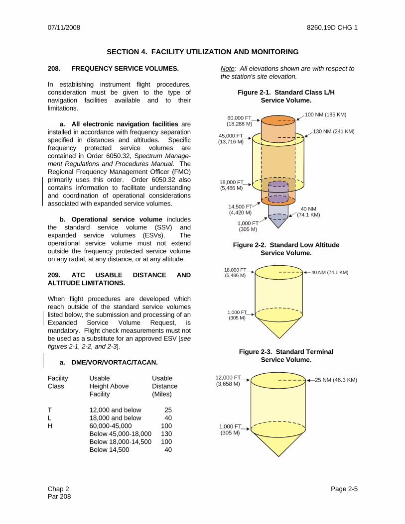
208. FREQUENCY SERVICE VOLUMES. In establishing instrument flight procedures, consideration must be given to the type of navigation facilities available and to their limitations. a. All electronic navigation facilities are installed in accordance with frequency separation specified in distances and altitudes. Specific frequency protected service volumes are contained in Order 6050.32, Spectrum Manage-ment Regulations and Procedures Manual. The Regional Frequency Management Officer (FMO) primarily uses this order. Order 6050.32 also contains information to facilitate understanding and coordination of operational considerations associated with expanded service volumes. b. Operational service volume includes the standard service volume (SSV) and expanded service volumes (ESVs). The operational service volume must not extend outside the frequency protected service volume on any radial, at any distance, or at any altitude. 209. ATC USABLE DISTANCE AND ALTITUDE LIMITATIONS. When flight procedures are developed which reach outside of the standard service volumes listed below, the submission and processing of an Expanded Service Volume Request, is mandatory. Flight check measurements must not be used as a substitute for an approved ESV [see figures 2-1, 2-2, and 2-3]. a. DME/VOR/VORTAC/TACAN. Facility Usable Usable Class Height Above Distance Facility (Miles) T 12,000 and below 25 L 18,000 and below 40 H 60,000-45,000 100 Below 45,000-18,000 130 Below 18,000-14,500 100 Below 14,500 40
Note: All elevations shown are with respect to the station's site elevation.
Figure 2-1. Standard Class L/H
Service Volume.
100 NM (185 KM)60,000 FT(18,288 M)
45,000 FT(13,716 M)
18,000 FT(5,486 M)
14,500 FT(4,420 M)
1,000 FT(305 M)
40 NM(74.1 KM)
130 NM (241 KM)
Figure 2-2. Standard Low Altitude Service Volume.
18,000 FT(5,486 M)
1,000 FT(305 M)
40 NM (74.1 KM)
Figure 2-3. Standard Terminal Service Volume.
12,000 FT(3,658 M)
1,000 FT(305 M)
25 NM (46.3 KM)

8260.19D CHG 1 07/11/2008
Page 2-6 Chap 2 Par 209
b. NDB. Facility Distance Class (Miles) COMLO Note: Low frequency 15 MH beacons have no 25 H standard height 50 HH limitations 75 c. ILS. Height Above Distance Facility Facility (Miles) Localizer (FC) 4,500 and below 18 Localizer (BC) 4,500 and below 18 Glide Slope (2o-4o) varies with angle 10 d. MLS [see figures 2-4 and 2-5]. Height Above Distance Facility Facility (Miles) MLS (FC) 20,000 and below 20 MLS (Back AZ) 5,000 and below 20 MLS EL 20,000 and below 20
Figure 2-4. MLS Azimuth Coverage.
+40° -40°
-40° +40°
0°
20 NM
20 NM FAA
AZIMUTH
*BACK AZIMUTH
*WHEN INSTALLED
CENTERLINEEXTENDED
Figure 2-5. MLS Elevation Coverage.
20,000 FT
TYPICALGLIDE PATH
EL20 NM
LOWERLIMIT
15°
3°
0.9°
210. REQUESTS FOR EXPANDED SER-VICE VOLUMES (ESV). a. When ATC requires use of NAVAIDs above/beyond limitations cited in paragraphs 209a through 209d, ATC submits an ESV request, with a description of the flight procedure requiring it. This request is first reviewed by the Frequency Management Officer (FMO). The FMO applies the criteria contained in Order 6050.32. If the FMO disapproves the request, it is returned to the originator without further action. FMO approved or restricted ESVs are then reviewed by the NFPO. b. The National Flight Procedures Office is responsible for accuracy, clarity, and practicality of the data. If the ESV request is unclear, or if the FMO approved request has restrictions or restrictive comments, it may be necessary to coordinate changes with the FMO and/or the originating office. FAA flight inspection determines if the facility supports the procedure. The flight inspector may utilize facility files and approve the ESV based on supporting data, providing the data was taken within the last five years. If sufficient data are not available, accomplish a flight check of the procedure before NFPO approval.

07/11/2008 8260.19D CHG 1
Chap 2 Page 2-7 Par 210
c. The procedures specialist when developing an instrument procedure may determine a requirement for an ESV; e.g., the instrument procedure is proposed beyond SSV. In this case, the procedures specialist processes an ESV electronically via the Expanded Service Volume Management System (ESVMS website) to obtain the FMO and, in turn, flight inspection approval. An ESV request MUST not be used as a substitute for proper instrument procedure design. d. Facility rotation due to magnetic variation change should have no effect on coverage; however, radials used will change. The NFPO initiates a change action via the Spectrum Management web site (ESVMS) on the date the rotation is effective. Prior to the publication cut-off date the NFPO will provide flight inspection a list of the currently approved ESVs against the effected facilities with the new radials and publication date annotated for review/action as appropriate. e. Describe holding patterns by radial, distance, altitude, and the maximum length holding pattern leg. f. An ESV is prepared and processed electronically via the Expanded Service Volume Management System via the FAA Intranet web site. An ESV can be placed on any VOR, ILS-DME, or TACAN. When a DME or TACAN and VOR are paired, both must have identical ESVs for safety reasons (except in those cases where the DME ESV supports DME/DME RNAV operations). ESVs may be added to any class of navaid facilities, including NDBs. 211. UTILIZATION OF LOCALIZERS AS EN ROUTE AIDS. The use of a localizer in en route flight procedures may be authorized in accordance with the following limitations: a. The use of the localizer for course guidance must start and end at an approved navigational fix. b. The use of localizers for en route instrument flight procedures must be limited to those instances where it is essential to air traffic control.
c. Appropriate navigational aids will be recommended at the earliest possible date in order to discontinue the use of the localizer for course guidance in the en route environment. 212. MONITORING OF NAVIGATION FACILITIES. a. Monitors. It is FAA policy to provide a monitoring system for all electronic navigation facilities used in support of instrument flight procedures. Internal monitoring is provided at the facility through the use of executive monitoring equipment that causes a facility shutdown when performance deteriorates below established tolerances. A remote status indicator may also be provided through the use of a signal-sampling receiver, microwave link, or telephone circuit. Very high frequency omnidirectional range (VOR), very high frequency omnidirectional radio range collocated with tactical air navigation (VORTAC), and ILS facilities as well as new non-directional beacons (NDBs) and marker beacons installed by the FAA, are provided with an internal monitoring feature. Older FAA NDBs and some nonfederal NDBs do not have the internal feature and monitoring is accomplished by other means. b. Monitoring Categories. Navigational facilities are classified in accordance with the manner in which they are monitored. (1) Category 1. Internal monitoring plus a status indicator installed at control point. (Reverts to a temporary Category 3 status when the control point is unmanned.) (2) Category 2. Internal monitoring with status indicator at control point inoperative, but pilot reports indicates the facility is operating normally. (This is a temporary situation that requires no procedural action.) (3) Category 3. Internal monitoring only. Status indicator is not installed at control point. (4) Category 4. Internal monitor not installed. Remote status indicator provided at control point. This category is applicable only to nondirectional beacons.

8260.19D CHG 1 07/11/2008
Page 2-8 Chap 2 Par 213
213. UTILIZATION OF MONITORING CATEGORIES. a. Category 1 facilities may be used for instrument flight procedures without limitation. b. Category 2 is a temporary condition not considered in procedures development. The Air Traffic Organization is responsible for issuing NOTAMs on these out-of-service facilities when pilot reports indicate facility malfunction. c. Category 3 facilities may be used in accordance with the following limitations: (1) Alternate minimums must not be authorized if facility provides final approach course guidance; is required for procedure entry; is used to define the FAF; or is used to provide missed approach guidance. See also para-graph 853b. (2) When a facility is used to designate a stepdown fix, alternate minimums must be no lower than the circling minimums required without the stepdown fix. (3) Consider denying or adjusting terminal routes that require reception of succeeding Category 3 facilities to avoid obstacles. (4) Dogleg airways or routes must not be predicated on these facilities. (5) Navigational fixes developed from crossing radials of Category 3 facilities must not be used to break a minimum en route altitude (MEA) to higher MEA (can be used as a break to a lower MEA). d. Category 4 facilities may be used in accordance with the following limitations: (1) Alternate minimums may be authorized when the remote status indicator is located in an FAA ATC facility, and then only during periods the control point is attended.
(2) If the control point is other than an FAA facility, a written agreement must exist whereby an ATC facility is notified of indicated changes in facility status.
Note: Failure of this Category 4 status indicator or closure of the control point will render the facility and the approach procedure unusable during the outage.
214. UTILIZATION OF 75 MHz MARKERS. The 75 MHz markers may be used as the sole source of identification with the following limitations: a. Missed Approach Point (MAP). Markers may be authorized as missed approach points for nonprecision approaches, provided a remote status indicator (RSI) is installed at an ATC facility. b. Final Approach Fix (FAF). As a non-precise final approach fix, the marker must be monitored if alternate minimums are authorized. The marker need not have an RSI if collocated with a compass locator with a remote status indicator. c. Course Reversals. Procedure turns and holding must not be authorized from a 75 MHz marker. d. Breaks in MEAs. The 75 MHz markers must NOT be used to define the point where an en route climb to a higher altitude is required (may be used as a break to a lower altitude). e. DP Turn Points. The 75 MHz markers must not be used to identify turn points on Departure Procedures. See Order 8260.46, Departure Procedure (DP) Program, para-graph 10.
07/11/2008 8260.19D CHG 1
Chap 2 Page 2-9 Par 215
SECTION 5. IMPLEMENTING EPOCH YEAR MAGNETIC VARIATION (MV) 215. GENERAL. This section establishes the MV program, identifies participating offices, assigns responsi-bilities, and provides guidelines for accomplishing the tasks necessary for implementing, main-taining, and systematically updating Epoch Year Magnetic Variation Values. a. Background. The National Oceanic and Atmospheric Administration (NOAA), National Ocean Service (NOS), and the National Geodetic Survey (NGS), for all areas of the United States and its territories for application to navigation charts and maps, determine the magnetic variation (MV). Changing values for MV are tabulated and published on a 5-year epoch basis; e.g., 85, 90, 95, 00, 05, etc. In order to assist in stabilizing the National Airspace System (NAS), a fixed value of MV is assigned to each navigational aid and airport as the Magnetic Variation of Record. This value is applied to true directions to obtain the magnetic values for radials, courses, bearings, and headings published in instrument flight procedures. Periodic updating of the MV assigned to navigation facilities is required to maintain reasonable proximity of alignment with the earth's ever-changing magnetic field. b. Participating Offices. Management and control of Epoch Year MV values require action by the following offices: (1) National Aeronautical Charting Office (NACO). (2) Technical Operations Aviation System Standards (AJW-3). (3) Military Organizations. (4) National Flight Data Center (NFDC). (5) Western, Central, and Eastern Technical Operations. (6) Regional Airports Divisions.
216. RESPONSIBILITIES.
a. NACO.
(1) Publish isogonic lines or segments on appropriate aeronautical charts based on current Epoch Year values. (2) Revise en route aeronautical charts and Airport/Facility Directives (AFDs) to reflect revised MV assignments to navigation facilities in accordance with information published in the National Flight Data Digest (NFDD). (3) Revise en route charts to apply yearly MV change values to RNAV (“Q” and “T”) route Magnetic Reference Bearings (MRB) during the first airspace charting cycle of each calendar year. b. Technical Operations Aviation System Standards. (1) Function as the focal point for all information relating to application of MV to the following elements of the NAS: navigational aids, airports, instrument flight procedures; and for coordination and liaison between AJW-3 and the Regional Airports, Air Traffic, and the applicable Technical Operations Service Area offices with respect to matters pertaining to change in navigational aid or airport MV of Record and its effect on instrument flight procedures. (2) Function as the focal point for FAA and all NAS Facilities flight inspection requirements and coordination. Terminal facilities (other than VOR, VOR/DME, TACAN, VORTAC, and radar systems) do not require flight inspection of MV changes. (3) Determine whether NOTAM action is necessary when required procedural adjustment action or MV change is not accomplished by the effective date of amended instrument procedures or revised en route charts. (4) For FAA and all NAS Facilities, assign and maintain MVs of record for navigational facilities and airports in whole degree increments. MVs of record are available in the AVNIS facility database. For new or relocated facilities, and new or revised instrument

8260.19D CHG 1 07/11/2008
Page 2-10 Chap 2 Par 216
procedures, apply the appropriate MV. Analyze each facility identified as a candidate for revised MV assignment to determine if facility rotation and/or redesignation of radials are required. (5) Develop and maintain an official listing/record of navigational aids and airports by geographical location at the end of each Epoch Year to indicate the currently assigned MV of most recent Epoch Year's MV, and the projected MV for the next Epoch Year. For the purpose of planning and implementation, maintain a current listing of those candidate navigational aids and airports with a difference of 2 degrees or more between the MV of record and the nearest future Epoch Year value. (6) Notify NFDC (in AJR-32) of changes to assigned MV and the effective date of those changes for publication in the NFDD; notify other concerned offices having related responsibilities to ensure timely implementation of necessary actions. The effective date selected must allow sufficient time for procedures processing in accordance with established schedules. MV changes which affect only terminal instrument procedures may have an effective date concurrent with publication of a specific procedural amendment. (7) Amend instrument flight procedures as required, predicated on navigational aids or airports undergoing a change of MV of record. Conduct a thorough survey to determine the full impact the MV change will have on any instrument procedure. Such surveys must include high and low altitude airways/jet routes, direct routes, air carrier off-airway routes, fixes in both high and low altitude structures, terminal routes and fixes, obstacle departure procedures (ODPs), SIDs, STARs, and any other application to instrument flight procedures. Use the MV of record (or as officially changed) to develop instrument flight procedures - regardless of the MV shown on the airport diagram chart or similar product being used. (8) VOR, VOR/DME, and VORTAC facilities supporting the en route structure (which may or may not have instrument procedures predicated on them):
(a) Modify all fixes and IAPs. Modify all 14 CFR Part 95 Direct and Off-Airway (Non-Part 95) routes with documented radial(s) or bearing(s). Change ESVs. Make all modifica-tions to meet an effective date that coincides with the en route change cycle.
Note: A listing of affected fixes, holding patterns, DPs, SIDs, STARs, military training routes, preferred routes, and ATS routes may be obtained from NFDC.
(b) Coordinate changes with ATC (ARTCC and approach control) in an attempt to eliminate routes, fixes, and instrument procedures that are no longer required. (9) Navigational aids NOT supporting en route structure: (a) Initiate implementation of the nearest future Epoch Year MV whenever any instrument procedure is established or amended. The nearest future Epoch Year MV will become effective concurrent with publication of the amendment [see paragraphs 857n and 857o]. (b) Amend and process multiple instrument procedures to simultaneously become effective concurrent with the instrument procedure specified in the MV change notification to NFDC. (c) Submit revisions of all affected fixes with the instrument procedure(s). Change ESVs. (d) Amend radar and DF procedures when the airport MV of record is changed. If the DF is located at an off-airport site, obtain the MV for the antenna site; include MV and Epoch Year in the lower right corner of the Form 8260-10. See chapter 4, section 5. (10) Army Facilities. (a) Accomplish MV changes for U.S. Army facilities in the same manner as for civil facilities; however, obtain the installation commander's prior approval.

07/11/2008 8260.19D CHG 1
Chap 2 Page 2-11 Par 216
(b) Notify the appropriate military representatives, in writing, when the need to change the MV of other military facilities is identified. c. USAF. (1) Function as the focal point for all USAF application of MV for USAF facilities within and outside the NAS to include navigational aids, airports, and instrument flight procedures. (2) Function as the focal point for USAF non-NAS facility flight inspection requirements and coordination. Terminal facilities (other than VOR, VOR/DME, TACAN, VORTAC, and radar systems) do not require flight inspection of MV changes. (3) Determine whether NOTAM action is necessary when required procedural adjustment action or MV change is not accomplished by the effective date of amended instrument procedures or revised en route charts. (4) Assign and maintain MVs of record for USAF non-NAS navigational facilities and airports in whole degree increments. For new or relocated facilities, and for new or revised instrument procedures, apply the appropriate MV. Analyze each facility identified as a candidate for revised MV assignment to determine if facility rotation and/or re-designation of radials are required. (5) Maintain a listing/record of USAF navigational aids and airports by geographical location. Indicate the currently assigned MV of record and the projected MV for the next Epoch Year. For the purpose of planning and implementation, maintain a current listing of those candidate navigational aids and airports with a difference of 2 degrees or more between the MV of record and the nearest future Epoch Year value. (6) Notify NFPO of changes to USAF non-NAS facilities assigned MV and the effective date of those changes in order to generate a letter to NFDC for publication in the NFDD; notify other concerned offices having related responsibilities to ensure timely implementation of necessary actions. The effective date selected must allow sufficient time
for procedures processing in accordance with established schedules. MV changes, which affect only terminal instrument procedures, must have an effective date concurrent with publication of a specific procedural amendment. (7) Amend instrument flight procedures as required, predicated on navigational aids or airports undergoing a change of MV of record. Conduct a thorough survey to determine the full impact the MV change will have on any instrument procedure. Such surveys must include high and low altitude airways/jet routes, direct routes, air carrier off-airway routes, fixes in both high and low altitude structures, terminal routes and fixes, obstacle departure procedures (ODPs), SIDs, STARs, ESV’s, and any other application to instrument flight procedures. Use the MV of record (or as officially changed) to develop instrument flight procedures - regardless of the MV shown on the airport diagram or similar product being used. (8) USAF navigational facilities within the NAS:
(a) Maintain official listing of USAF facilities that are part of the NAS.
(b) Notify NFPO when MV changes are required. Allow sufficient time for modification of FAA fixes and IAPs as necessary. (9) USAF navigational facilities NOT within the NAS:
(a) Initiate implementation of the nearest future Epoch Year MV, as per paragraph 217a, whenever any instrument procedure is established or amended. The nearest future Epoch Year MV must become effective concurrent with publication of the amendment [see paragraphs 857n and 857o].
(b) Amend and process multiple instrument procedures to simultaneously become effective concurrent with the instrument procedure specified in the MV change notification to NFDC.
(c) Submit revisions of all affected fixes with the instrument procedure(s). Change ESVs, as required.
8260.19D CHG 1 07/11/2008
Page 2-12 Chap 2 Par 216
(d) Amend all procedures as, required, when the airport MV of record is changed. d. U.S. Navy. (1) Contact the NFPO to obtain the MV of record or MV assignments for new or relocated facilities to be applied to navigational aids or airports under Navy jurisdiction. (2) Coordinate with the NFPO to determine impact of MV changes for both military and public facilities. (3) Navy flight procedure develop-ment work generally follows the same requirements as NFPO's flight procedure development work, as outlined in paragraphs 216b(3) through (9). The NFPO will remain the office of primary responsibility for paragraphs 216b(1), (2), (4), and (5) functions. (4) Notify NFPO of changes to Navy, non-NAS facilities, assigned MV and the effective date of those changes in order to allow NFPO to generate a letter to NFDC for publication in the NFDD; notify other concerned offices having related responsibilities to ensure timely implementation of necessary actions. The effective date selected must allow sufficient time for procedures processing in accordance with established schedules. MV changes, which affect only terminal instrument procedures, must have an effective date concurrent with publication of a specific procedural amendment. (5) Navy navigational facilities within the NAS: (a) Maintain official listing of Navy facilities that are part of the NAS. (b) Notify NFPO when MV changes are required. Allow sufficient time for modification of FAA fixes and IAPs as necessary. e. Airports. (1) Amend IAPs, SIDs, and ODPs that specify runway designator numbers affected by MV change.
(2) Notify the applicable Air Traffic Service Area Office of the need for amendment action if STARs contain runway designator numbers affected by MV change. (3) Take appropriate NOTAM action if repainting of an affected runway is not accomplished on the required date. f. NFDC. When notified by the NFPO of any change to MV of record, publish a notice of change in the NFDD. An effective date of change must be included in the NFDD. g. Western (AJW-W), Central, (AJW-C), and Eastern (AJW-E) Technical Operations. Coordinate with the FPFO to obtain the MV of record for assignment to newly installed or relocated navigational aids. h. Regional Airports Division. Coordinate with the FPFO prior to establishing or revising runway designator numbers for an airport having one or more instrument approach or departure procedures, to determine the MV to be applied to the runway true bearing. Determination of the runway designator number should be a matter of joint agreement with the NFPO, and be accomplished sufficiently in advance to allow for procedural amendments. 217. GUIDELINES. The identification and selection of navigational aids or airports as candidates for revision of MV of record require careful consideration and evaluation of a number of factors - as the impact of MV changes can be considerable. The applicable Air Traffic Service Area Office may have to initiate or revise published air traffic procedures; the Technical Operations Service (AJW-0) is directly involved in facility rotations and requires proper coordination. The Airports Division, or appropriate military authority, may have to arrange for repainting of runway designator numbers [see paragraph 858e(2)(e)].
Note: Guidelines pertaining to runway designation marking relative to magnetic changes can be found in AC 150/5340-1, Standards for Airport Markings, paragraph 7d.

07/11/2008 8260.19D CHG 1
Chap 2 Page 2-13 Par 217
a. MV versus Epoch Year Value. When the difference between the MV of Record and the nearest future Epoch Year value of any navigational aid or airport is 3 degrees or more, the MV of record must be changed to the nearest future Epoch Year value. When the difference is less than 3 degrees, consider implementing the nearest future Epoch Year value when workload permits. Factors to consider include whether the navigational aid is isolated or in close proximity to one or more other facilities, whether on airport or away from an airport, and the impact on instrument flight procedures. b. Facilities on Airports. At airports with localizer(s) or more than one navigational aid, the MV at the airport reference point (ARP) must be designated and assigned to all facilities at that airport, including all components of the ILS. c. MV versus OC Chart Value. Where the assigned MV of record differs from the MV shown on the Obstruction Chart (OC), the assigned MV of record must be used in the development of instrument flight procedures. d. Runway bearing must be assigned the same MV as the airport.
Note: The actual runway bearing is published on airport diagrams to allow pilots to obtain a compass bearing check during runway line-up. This value may differ from the value computed during the assigned variation.
e. At major airport terminal areas, the ARP MV of record at the designated controlling airport may be used in determining the MV applied to all navigational aids serving the terminal areas. f. Standard Rules for Applying Magnetic Variation to True Radials, Bearings, and Courses. (1) Ground Based and Radar Facilities. (a) Utilize the facility Magnetic Variation of Record to determine magnetic tracks, and courses. (2) RNAV. (a) Magnetic variation to be applied to any track used in an RNAV instrument procedure is the magnetic variation of the aerodrome of intended landing except where en route VOR or NDB navigation aids are used as procedure fixes. RNAV track information is based on the true track from one fix to a succeeding fix. To determine the magnetic track, apply the published magnetic variation of the aerodrome to the procedure true track. Preferred RNP RNAV leg types (see RTCA DO- 201A) are defined so that magnetic variation is not a factor in establishing the ground track. Non-preferred leg types that follow a magnetic track to or from a fix are affected by magnetic variation errors. 218.-219. RESERVED.
8260.19D CHG 1 07/11/2008
Page 2-14 Chap 2 Par 220
SECTION 6. NOTICES TO AIRMEN (NOTAMs)
220. GENERAL. NOTAMs provide timely knowledge to airmen, and other aviation interests, of information or conditions that are essential to safety of flight. NOTAMs pertaining to instrument procedures remain in effect until the pertinent charts and publications are amended or the condition requiring the NOTAM ends. This section deals primarily with policy for issuing Flight Data Center (FDC) NOTAMs and NOTAM Ds when required to maintain the accuracy and currency of charted terminal and en route flight procedures. Also, see Order 8260.3, United States Standard for Terminal Instrument Procedures (TERPS), paragraph 150e. 221. NATIONAL NOTICE TO AIRMEN SYSTEM. A National Notice to Airmen System has been established to provide airmen with the current status of the National Airspace System (NAS). This system is under the purview of FAA’s Air Traffic Organization, Vice President of System Operations (AJR-0). Management and operational guidance is contained in Order 7930.2, Notices to Airmen (NOTAMs). The following is a brief summary of the different type NOTAMs and issues applicable to instrument procedure changes, NAVAID outages, and government chart corrections. a. FDC NOTAMs are issued through the U.S. NOTAM Office (USNOF) and primarily used to disseminate safety of flight information relating to regulatory material [see Order 7930.2, chapter 7, for specific FDC NOTAM categories]. FDC NOTAMs are numbered by the U.S. NOTAM System (USNS) to reflect the year of issuance and the sequence number for the calendar year, (e.g., 5/0445). FDC NOTAMs are transmitted on all Service B circuits, and stored in the Consolidated NOTAM System, after which they are entered in the Notices to Airmen Publication (NTAP) until canceled. The NTAP is distributed via U.S. mail and is available on-line at http://www.faa.gov/airports_airtraffic/air_traffic/publications/notices. b. FDC NOTAMs may be either temporary (T-NOTAMs) or permanent
(P-NOTAMs), as specified below, when used to promulgate changes to published instrument flight procedures, and corrections to U.S. Government charts. FDC NOTAMs must be prefixed with an action code as follows: (1) FI/T (Flight Information/ Temporary). Use this prefix when safety of flight issues require changes to SIAPs, airways, or textual DPs. If the condition requiring the NOTAM will be effective for more than four chart cycles (224 days), a procedure amendment (revised 8260-series form or P-NOTAM) must be submitted as soon as possible to allow publication of the change within the 224-day timeframe. When temporary conditions beyond the control of the NFPO; e.g., airport construction, NAVAID restrictions, temporary obstructions, etc., require NOTAM action, the NFPO will ensure the line of business (LOB) approving the temporary condition is advised of the procedural impact and the necessity of reconciling the condition as soon as possible so the temporary NOTAM can be canceled within the 224-day timeframe. If the condition cannot be corrected within 224 days, appropriate procedure amendments/airway revisions must be processed as noted above (see paragraph 813). (2) FI/P (Flight Information/ Permanent). Use this prefix only to promulgate U.S. Government charting correction information. Cartographic agencies may initiate immediate changes to charted information based upon the P-NOTAM information. P-NOTAMs may NOT be used for changes to SIAPs, airways, takeoff minimums, ODPs, SIDs, or STARs. Refer to paragraphs 224b and 224c for graphic DP and STAR NOTAM procedures. c. NOTAM-Ds are issued under the Flight Service Stations' Accountability System and receive the same dissemination as the surface weather report for the originating station. NOTAM Ds provide the user with current information on an hourly basis and are numbered to reflect the month of issuance and the sequence number within the month, (e.g., 06/018). 222. FDC T-NOTAM PREPARATION, REVIEW, AND TRANSMITTAL.
07/11/2008 8260.19D CHG 1
Chap 2 Page 2-15 Par 222
a. The NFPO is the primary office responsible for formulating procedural and airway FDC T-NOTAMs and forwarding them for transmittal. The NFPO is also the office of primary responsibility for developing specific internal guidance for T-NOTAM preparation, quality control, transmittal, cancellation, and follow-up actions. This guidance must be developed in concert with the NFDC, the NACO Requirements and Technology Staff (R&T), and the U.S. NOTAM Office (USNOF). AFS-420 must be provided the opportunity to review and comment on the procedures prior to implementation. As a minimum, the following items must be included in the guidance: (1) Procedures to ensure that all FDC T-NOTAMs are coordinated with the affected ARTCC facility at the time of submission, or if unable, during the next normal workday [see Order 8260.3, Volume 1, paragraph 150]. The NFPO/FPFO must also attempt to notify the airport manager at the affected location whenever possible.
Note: ARTCCs are responsible for forward-ing FDC NOTAM information to the affected terminal facilities under Order 7930.2, paragraph 2-2-3.
(2) Procedures to ensure ALL FDC T-NOTAMs are reviewed for accuracy, completeness, content, etc. prior to submission. (3) Procedures to ensure the NFDC is provided an information copy of all Instrument Flight Procedures (IFP) T-NOTAMs and cancellations to ensure that the NTAP is properly maintained. (4) Procedures to ensure the USNOF notify the submitting agency and the NFDC of all changes in instrument procedure FDC NOTAM numbering. (5) Procedures to ensure all FPFO or Flight Inspection Operations Group (FIOG) initiated FDC NOTAMs and NOTAM Ds are coordinated through the NFPO.
b. The NFPO must review amended SIAP charts, take-off minimums, textual ODPs, and en route charts to ensure procedural changes are charted correctly and cancel NFPO initiated FDC T-NOTAMs on the effective date of the amended procedure(s).
c. The NFDC will review applicable FDC NOTAMs for accuracy, format, completeness, and database agreement. Discrepancies noted by NFDC will be forwarded to the originating NFPO branch for resolution. NFDC is also responsible for compiling NOTAMs for inclusion in the NTAP. d. The USNOF is responsible for ensuring that FDC NOTAMs are in the proper format under this directive and Order 7930.2. Questions/discrepancies will be addressed to the submitting agency or the NFPO as appropriate. The USNOF must ensure that NFDC and the FDC NOTAM originating office are appraised of all changes in instrument procedure related FDC NOTAM numbers; e.g., when a NOTAM is canceled and reissued due to typographical error, etc. The NACO Requirements and Technology Team must be notified if changes are made to P-NOTAMs correcting U.S. Government charts. The FDC NOTAMs affecting FAA developed military SIAPs at civil locations must be issued separately and forwarded to the USNOF military representative. 223. FDC P-NOTAM PREPARATION, REVIEW, AND TRANSMITTAL. a. The NACO Requirements and Technology (R&T) Team is the primary office responsible for formulating FDC P-NOTAMs used to correct chart printing and compilation errors related to all U.S. Government aeronautical charting products and forwarding them for transmittal. b. When a printing or compilation error is noted on a U.S. Government aeronautical charting product; e.g., the Terminal Procedures Publication (TPP), NACO, NFPO, NFDC, and the FAA Cartographic Standards Branch will jointly determine if the error can be safely addressed by NOTAM or whether the instrument flight procedure must be suspended pending issuance of a replacement chart. AFS-420 will provide operational/criteria input as required. c. The NACO R&T Team is also the office of primary responsibility for developing specific internal guidance for P-NOTAM preparation, quality control, transmittal, cancellation, and follow-up actions. This guidance must be developed in concert with the NFDC, the NFPO, and the USNOF. AFS-420

8260.19D CHG 1 07/11/2008
Page 2-16 Chap 2 Par 223
must be provided the opportunity to review and comment on the procedures prior to implementation. As a minimum, the following items must be included in the guidance: (1) Procedures to ensure that all FDC P-NOTAMs are coordinated with the affected ARTCC facility at the time of submission, or if unable, during the next normal workday. The NACO must also attempt to notify the airport manager at the affected location, whenever possible. (2) Procedures to ensure that ALL FDC P-NOTAMs are reviewed for accuracy, completeness, content, etc. prior to submission. (3) Procedures to ensure that the USNOF notifies the NACO Requirements and Technology Team and the NFDC of all changes in chart correction FDC P-NOTAM numbering; e.g., when a NOTAM is canceled and re-issued by the USNOF. (4) Procedures to ensure the NFDC is provided an information copy of all chart correction P-NOTAMs and cancellations to ensure that the NTAP is properly maintained. 224. INSTRUMENT APPROACH and TEXTUAL DEPARTURE PROCEDURE NOTAMs. A complete review and a new amendment are the preferred methodology for permanent procedure changes, particularly when applying new or revised TERPS criteria. However, it is recognized that this may not always be possible due to time constraints workload, staffing level, etc. An FDC T-NOTAM followed by an abbreviated 8260-series form within the allotted 224 days is an equally effective means of updating SIAP charts and textual DPs within the following guidelines: a. Whenever the need for a NOTAM to a procedure arises, AJW-32 must review the procedure and ascertain that there is no other safety of flight changes required. Do NOT prepare a NOTAM solely to address minor non-safety related discrepancies to a SIAP. b. Procedural minimums must not be lowered by NOTAM except as allowed by Order 8260.3, Volume 1, paragraph 150e.
c. Exercise caution in initiating or adding a NOTAM to a procedure when there is already a current NOTAM in effect for the procedure. In many cases close follow-up action, including canceling and reissuing NOTAMs, will be necessary to ensure there is no confusion for pilots and chart producers. All FDC NOTAMs must be issued against the currently published procedure. Example:
The currently published SIAP is AMDT 3 and AMDT 3A has been forwarded but not yet published. Another T-NOTAM is required prior to AMDT 3A. Issue a T-NOTAM against AMDT 3. When AMDT 3A is published, the T-NOTAM must be canceled and reissued for AMDT 3A.
d. When changes to civil procedures also affect FAA-developed military procedures at civil or joint-use airfields, the NFPO must issue a separate FDC or military-series NOTAM for the military procedure as specified in Orders 8260.15, United States Army Terminal Instrument Procedures Service, and 8260.32, United States Air Force Terminal Instrument Procedures Service. The NFPO must request the USNOF to forward the civil NOTAM and the reason to the cognizant military authority for appropriate military NOTAM action. e. NOTAM requirements for FAA developed U.S. Army procedures must be processed under Order 8260.15. NOTAM requirements for FAA developed U.S. Air Force procedures at civil airfields must be processed under Order 8260.32. 225. GRAPHIC ODP, SID, and STAR NOTAM PREPARATION, REVIEW, AND TRANSMITTAL. a. Changes to graphic ODPs and SIDs must be promulgated as NOTAM Ds under Order 7930.2. The NFPO is responsible for formulating NOTAM Ds for graphic ODPs and SIDs and forwarding them for transmittal by the USNOF. These NOTAMs are issued by the USNOF using the accountability code “USD.” The following format examples are provided: USD 12/001 SAN BORDER THREE DEPARTURE JULIAN TRANSITION: FROM
07/11/2008 8260.19D CHG 1
Chap 2 Page 2-17 Par 225
OVER BROWS INT VIA JLI R-182 TO JLI VORTAC USD XX/XXX LAX CHATY TWO DEPARTURE, GORMAN TRANSITION: MINIMUM ALTITUDE BROWS, INT TO GMN VORTAC, 8,000 FT In the first example above, “USD” is the NOTAM accountability code; “12/001” is the NOTAM number, which is assigned by the USNOF (first NOTAM (D) issued in December); “SAN” indicates the three-letter airport identifier; the remainder is the NOTAM text. b. Changes to STARs requiring NOTAM action are also promulgated as NOTAM Ds. The appropriate ARTCC is responsible under Order 7930.2 for initiating, tracking, and canceling STAR NOTAMs. c. The NFPO is the office of primary responsibility for developing specific internal guidance for DP NOTAM D preparation, quality control, transmittal, cancellation, and follow-up actions. This guidance must be developed in concert with the NFDC, NACO R&T Team, and the USNOF. AFS-420 must be provided the opportunity to review and comment on the procedures prior to implementation. The following items must be included in the guidance: (1) Procedures to ensure that ALL NOTAM Ds are reviewed for accuracy, completeness, content, etc. prior to submission. (2) For SIDs serving multiple air-ports, a separate NOTAM D must be prepared for each airport affected by the SID. (3) Temporary and permanent conditions may be promulgated via the NOTAM D process; however, NOTAM Ds must not be used as a source to effect charting changes. Permanent procedural changes to graphic DPs must be made via a new or amended 8260-15 series form within 224 days of the issuance of the associated NOTAM D. (4) The USNOF must review each NOTAM D to ensure formatting, contractions, etc. are correct and assign the NOTAM number. Questionable items must be resolved with the originator prior to issuance. (5) Once issued, the NFPO is responsible for obtaining the NOTAM D
number from the USNOF, tracking, and canceling the NOTAM when the condition requiring the NOTAM is no longer applicable. 226. GENERAL NOTAM D ACTIONS. a. When a NOTAM D is issued closing an airport permanently, an FDC NOTAM need not be issued denying use of a SIAP. A routine procedure cancellation should be processed. b. When a NOTAM D is issued to shut down a facility permanently, only routine cancellations of procedures predicated on that facility are required. FDC NOTAMs may be required for other procedures supported by the affected facility. c. When a NOTAM D is issued closing a runway, an FDC NOTAM need not be issued denying straight-in minimums to that runway. If the closing is permanent, routine procedure cancellations, including takeoff/departure procedures, must be processed immediately. d. When a NOTAM D is issued for a facility shutdown or outage, an FDC NOTAM denying SIAP use is not required for those SIAPs using only that facility. However, other SIAPs in the vicinity must be reviewed to determine if that facility supports courses or fixes; in such cases, those SIAPs require an FDC NOTAM. Particular attention must be given to fixes supporting stepdown minimums and missed approach procedures, which are predicated on the out-of-service facility. It is not necessary to issue NOTAMs for fixes and terminal route segments, which are related to unusable airway segments from the subject facility. Do not issue “Radar Required” NOTAMs on unusable or restricted airway segments. Also, see paragraph 462 for ILS Cat II/III NOTAM restrictions. e. Area Navigation (RNAV) Substitution. Aircraft equipped with RNAV systems may substitute them for inoperative ground NAVAIDs. However, RNAV systems must not be substituted for NAVAIDS providing final approach course guidance on instrument approach procedures. (1) When the use of an instrument approach procedure, departure procedure (SID or ODP), or standard terminal arrival (STAR) is restricted or prohibited by NOTAM

8260.19D CHG 1 07/11/2008
Page 2-18 Chap 2 Par 226
because of a NAVAID (VOR, TACAN, NDB, compass locator, or DME) outage, the NOTAM does not apply to aircraft equipped with suitable GPS RNAV systems. For clarification, state the reason for the restriction in the text of the procedural NOTAM D or FDC NOTAM. Examples: A DME antenna is out of service: "DME MINIMUMS NA EXCEPT FOR AIRCRAFT EQUIPPED WITH SUITABLE RNAV SYSTEM WITH GPS, ORD DME OTS." An LOM used for procedure entry and/or missed approach clearance limit for an ILS approach is out of service: "PROCEDURE NA EXCEPT FOR AIRCRAFT EQUIPPED WITH SUITABLE RNAV SYSTEM WITH GPS, GR LOM OTS." A VOR is used in a departure procedure (ODP or SID) is out of service: "GEYSER THREE DEPARTURE NA EXCEPT FOR AIRCRAFT EQUIPPED WITH SUITABLE RNAV SYSTEM WITH GPS, JAC VOR OTS." (2) In certain circumstances, AFS-400 may determine that the use of RNAV systems that utilize DME/DME/IRU inputs should be allowed. In these instances, insert the phrase "OR DME/DME/IRU" after "SUITABLE RNAV SYSTEM WITH GPS." Include any required DME facilities to support DME/DME/IRU operations.
Example: "HOOVER THREE DEPARTURE NA EXCEPT FOR AIRCRAFT EQUIPPED WITH SUITABLE RNAV SYSTEM WITH GPS OR DME/DME/IRU, PGS VOR OTS. BLD AND DRK MUST BE OPERATIONAL FOR DME/DME/IRU ON PEACH SPRINGS TRANSITION. DRAKE TRANSITION NA FOR DME/DME/IRU." f. When a NOTAM D removes a localizer from service, the SIAP is unusable. If the GS is out, the precision approach is unusable. If other ILS components are out, the inoperative table applies. g. When radio control of approach lights or runway lights is commissioned or the frequency is changed, Flight Inspection issues a NOTAM D in accordance with Order 8200.1,
United States Standard Flight Inspection Manual. h. When Airways Facilities issues a NOTAM suspending Category II/III minimums, the NFPO will then amend procedures as required. 227. AIRWAY NOTAMs. When a restriction or a change to an airway requires a NOTAM, NFPO must prepare and forward an FDC T-NOTAM following the procedures in paragraph 223. a. NOTAMs, reflecting airway changes within one or more ARTCC’s airspace, are issued under the affected ARTCC identifier as Center Area NOTAM (CAN) FDC NOTAMs on the NOTAM circuit. The formats specified in Order 7930.2, chapter 7, section 1 must be followed regarding the number of ARTCCs and states affected. b. Airway changes involving a single state and one or more ARTCCs must be issued with the ARTCC identifier followed by the two-letter state code. The two-letter state code must also follow all NAVAID and fix designators. Examples: "FDC 7/0001 ZFW OK FI/T AIRWAY ZFW ZKC. V140 SAYRE (SYO) VORTAC, OK TO TULSA (TUL) VORTAC, OK MEA 4,300. FDC 7/0002 ZKC OK FI/T AIRWAY ZFW ZKC. 140 SAYRE (SYO) VORTAC, OK TO TULSA (TUL) VORTAC, OK MEA 4,300. REASON: TEMPORARY NEW TOWER. OE 07-ASW-0123." c. If the airway NOTAM affects one but less than four ARTCCs and multiple states, issue one NOTAM for each affected ARTCC. If the NOTAM affects four or more ARTCCs, send one NOTAM using "FDC” as the facility identifier. d. If the restriction will exceed the time limit established in paragraph 222b, forward an updated Form 8260-16 and/or 8260-2 simultaneously to NFDC and NACO for charting.

07/11/2008 8260.19D CHG 1
Chap 2 Page 2-19 Par 228
228. FDC NOTAMs FOR SPECIAL INSTRUMENT APPROACH PROCEDURES (SPECIALS). FDC T-NOTAMs may also be used to promulgate safety of flight information relating to Specials provided the location has a valid landing area identifier and is serviced by the U.S. NOTAM system. The AJW-3 NOTAM Entry System (NES) will provide immediate feedback as to whether the location is included in the NOTAM system. There are four possible considerations to determine FDC NOTAM action for Specials. a. If the Special is maintained by the NFPO and the location is in the U.S. NOTAM system, then procedures for NOTAM processing by the NFPO will be similar to the procedures used for public, part 97 instrument approach procedures. Additionally, when preparing the NOTAM for submission, include the word "SPECIAL" in parenthesis immediately following the city/state and prior to the procedure title [see paragraph 229 for an example]. The NFPO will notify the RFSD-AWOPM as soon as practicable. b. If the Special is not maintained by the NFPO but the location is in the U.S. NOTAM system, then the organization responsible for maintaining the procedure will notify the applicable RFSD-AWOPM of the change/ outage. The RFSD-AWOPM will contact the NFPO with the appropriate information, who will take appropriate NOTAM action. If the RFSD-AWOPM cannot be immediately contacted and the condition is critical to flight safety, the Regional FPFO or the NFPO will be contacted directly and provided adequate information to initiate immediate NOTAM action. The NFPO will notify the RFSD-AWOPM as soon as practicable.
Note: After duty hours, contact the stand-by NFPO representative at (405) 954-8260.
c. If the Special is maintained by the NFPO and the location is not in the U.S. NOTAM system, then the NFPO will notify the applicable RFSD-AWOPM of the change/ outage. The RFSD-AWOPM must contact the user(s) of the procedure to disseminate appropriate action (e.g., NA the procedure, raise applicable minimums, etc.).
d. If the Special is not maintained by the NFPO and the location is not in the U.S. NOTAM system, then the organization responsible for maintaining the procedure will notify the applicable RFSD-AWOPM of the change/outage. The RFSD-AWOPM must contact the user(s) of the procedure to disseminate appropriate action (e.g., NA the procedure, raise applicable minimums, etc.). 229. NOTAM CONTENT. a. FDC SIAP NOTAMs must identify the procedure being amended and the current amendment number. The NOTAM must be as concise as possible, and must NOT contain information that could be published at a later date by a routine amendment. For example, changes to the touchdown zone or airport elevation, which does not affect visibility mini-mums, do not require NOTAM action. b. The text must be prepared by the NFPO using plain language and those contractions found in the NTAP. Specialists must keep in mind that the NOTAM is directed to the pilot, and should be worded so that the intended change will not be misinterpreted. Avoid the use of internal cartographic instructions that have no meaning to pilots. Spell out NAVAID names in clear text followed by the identifier. If it appears that the NOTAM length will exceed 20 lines, refer to Order 7930.2, paragraph 4-3-4. c. For temporary obstructions, include the type, elevation, distance, and direction from the airport or runway threshold, as appropriate, as the last line of the text. d. Include a reason for the NOTAM following the NOTAM text. This information will not be transmitted as a part of the NOTAM text, but will inform the NFDC and the USNOF of the basis for the NOTAM. It will also ensure the data is retained in the NOTAM historical files. Example: FDC 7/_____ ORD FI/T CHICAGO O'HARE INTL, CHICAGO, IL. VOR RWY 22R AMDT 8B... MDA 1400/HAT 750, VIS 1-1/2 ALL CATS. TEMPORARY CRANE 1100 MSL 1.2 NM SE OF RWY 23. (Specify distances less than 1 NM in feet.)

8260.19D CHG 1 07/11/2008
Page 2-20 Chap 2 Par 229
REASON: TEMPORARY CRANE FOR 90 DAYS. OE 06-AGL-2689 FDC 7/GPT FI/T GULFPORT-BILOXI INTL, GULFPORT, MS. VOR RWY 31 AMDT 18... S-31 MDA 720/HAT 693 ALL CATS. VIS CAT C 2, CAT D 2-1/2. CIRCLING MDA 720/HAA 692 ALL CATS. VIS CAT C 2, CAT D 2-1/2. RADAR 1 AMDT 3… VOR/DME OR TACAN RWY 31 ORIG. S-31 MDA 660/HAT 633 ALL CATS. VIS CAT C 1-3/4, CAT D 2, CAT E 2-1/4. CIRCLING CATS A/B MDA 660/HAA 632. TEMPORARY CRANE 410 MSL 1.5 NM SE OF RWY 31. REASON: TEMPORARY CRANE FOR 160 DAYS. OE 07-ASO-0101 FDC 7/_____ LAN FI/T CAPITAL CITY, LANSING, MI. ILS RWY 10R AMDT 8A... ILS RWY 28L AMDT 24... VOR RWY 6 AMDT 23B... VOR RWY 24 AMDT 7E... CIRCLING MDA 1420/HAA 559 ALL CATS. REASON: NEW BUILDING, 1115 MSL. OE 07-AGL-0123 Note: Since the above condition is permanent, SIAP Amendments must be processed within 224 days.
“FDC 7/ PAJN FI/T JUNEAU INTERNATIONAL, JUNEAU, AK (SPECIAL) LDA-2 RWY 8 AMDT 9… PROCEDURE TURN NA. REASON: PROCEDURE TURN (PT) STEP-DOWN FIX GREATER THAN 4 NM FROM PT FIX. FDC 7/_____ AXH FI/T HOUSTON-SOUTHWEST, HOUSTON, TX. NDB RWY 28 AMDT 4... LOC/DME RWY 10 AMDT 2A...CHANGE ALL REFERENCE TO RWY 10-28 TO RWY 9-27.” REASON: RUNWAYS RENUMBERED FOR MAGNETIC VARIATION CHANGE. FDC 5/ FI/P CORRECT U.S. GOVERNMENT CHART NORTH ATLANTIC ROUTE CHART, EFFECTIVE 17 MAR 2005… CORRECT ROUTE IDENTIFIER A763 BETWEEN GRAND TURK ISLAND (GTK) VORTAC AND AGUADILLA (BQN) VORTAC TO R763. FDC 5/ FI/P CORRECT U.S. GOVERNMENT IFR EN ROUTE LOW ALTITUDE CHART L-3, PANEL C, EFFECTIVE 18 JAN 2007... VICTOR AIRWAY V458 BTW JLI VORTAC (N 33 08 25.651/W116 35 09.365) AND KUMBA INT (N32 45 43.180/W116.03 13.370) MEA SHOULD READ 7700. FDC 7/ 7D2 FI/P OAKLAND/TROY, TROY, MI. VOR OR GPS-A, AMDT 3... CORRECT FAF TO READ PERLS INT. VS PERSL INT.

07/11/2008 8260.19D CHG 1
Chap 2 Page 2-21 Par 230
SECTION 7. QUALITY/STANDARDIZATION OF INSTRUMENT FLIGHT PROCEDURES
230. NFPO ACTION. a. The NFPO is responsible for the accuracy of instrument flight procedures it develops, and for establishing and conducting a system of quality control that ensures such procedures conform to applicable criteria, standards, and policy. b. The NFPO’s system of quality control must ensure that all flight procedures and NOTAMs submitted to NFDC are of a professional quality that will not require corrections or changes following release. c. When unusual circumstances exist, for which policy is not clear or is nonexistent, request a policy determination from AFS-460 PRIOR TO submission for publication. AFS-460 will issue appropriate instructions as necessary. d. Instrument charts produced by the National Aeronautical Charting Office (NACO) will be reviewed by the NFPO, upon receipt, for
variations from information submitted for publication and for clarity of the graphic portrayal. Charting errors detected must be forwarded directly to NACO R&T for corrective action under paragraph 224b. Charts that do not clearly portray the procedure(s) as designed should be referred to AFS-460 and the NACO, with recommendations for charting improvements. 231. AFS-460 ACTION. a. AFS-460 is responsible for providing oversight of the NFPO Quality Assurance (QA) process to determine conformance with applicable criteria, standards, and policy. b. Preliminary reviews may be conducted by AFS-460 upon request by the NFPO. When unusual circumstances exist, AFS-460 will issue appropriate instructions to the NFPO as necessary. 232.-239. RESERVED.

8260.19D CHG 1 07/11/2008
Page 2-22 Chap 2 Par 240
SECTION 8. PERIODIC REVIEW OF INSTRUMENT FLIGHT PROCEDURES
240. GENERAL. a. This section prescribes the minimum frequency of review of instrument procedures. When deemed necessary, and in the interest of safety or for other proper justification, make more frequent reviews. Review all instrument proce-dures to ensure that requirements for obstacle clearance, navigational guidance, safety, and practicality are met. Immediately comply with changes to criteria that relate to safety of flight. Use the review to determine if other changes to criteria and policy impact the current procedure. These changes include, but are not limited to such items as procedure naming, requirements to add/remove/modify chart notes, etc. Consideration must also be given to the impact of OEs, F&E, and AIP projects pertinent to the procedure review process. Reviews will be completed within the timeframes specified in paragraph 241. Document all required changes in the NFPO Procedure Tracking System (PTS), including criteria/policy and how they impact the current procedure during the review. b. A review is considered complete if it occurs in the period from one month prior to one month after the month in which the review is due; e.g., if the review is due in July, the window is June 1 to August 31. If the window is met, the procedure review due month remains unchanged. However, if the review occurs outside of the specified window, the next review is due in the month in which the review was actually completed. c. Document periodic reviews to show when the review was conducted.
Note: The method (e.g., Spreadsheet, memorandum, etc.) used to document the periodic review is left up to the procedure development authority.
d. When facility restrictions are established or changed, review all associated flight procedures. Take particular care to evaluate unpublished procedures such as off-airway, direct, and substitute routes.
241. NFPO ACTION. a. SIAPs, SIDs, ODPs, and STARs. (1) Review at least once every two years. (2) Review all feeder, initial, inter-mediate, final, circling, missed approach, and departure procedure areas for any changes that would affect flight altitudes. To avoid proliferation of conflicting data on IFPs at an airport, the periodic review should include all procedures at that airport [see paragraph 811a]. (3) Ensure that all procedures are contained within controlled airspace as prescribed in chapter 5. (4) Ensure that minimums meet criteria. Review IFP forms for conformance to current standards. Check published IFP charts and text for correct portrayal. (5) Verify current magnetic variation values. (6) Verify continued need for IFPs based on usage rate, economic need, etc. Cancel IFPs that are no longer required. (7) Verify the validity of existing waivers. Cancel waivers no longer required. (8) Coordinate proposed IFP changes (including FDC NOTAMs) in advance with the applicable FPFO, airport management, and servicing air traffic control facility when application of new or revised criteria raises minimum procedure altitudes and/or increases landing minimums. b. Airways, Airway Segments, and Routes. (1) Review at least once every 4 years.

07/11/2008 8260.19D CHG 1
Chap 2 Page 2-23 Par 241
(2) Verify controlling obstacles and assure that authorized altitudes meet obstacle clearance requirements. Use current en route charts as airway checklists. (3) Verify continued need for off-airway and Part 95 direct routes. Cancel routes that are no longer required. c. Fixes. (1) Review all fixes in conjunction with the associated IFPs, airways, or routes [see section 10]. Assure that Form 8260-2 entries for facility type, class, radial/course/bearing, distances, least divergence angle, and charting requirements are correct. Verify holding requirements and controlling obstructions. (2) Cancel fixes and holding which are no longer needed.
d. All Procedures. (1) Establish and maintain a system of control to assure that reviews are accomplished. (2) Take remedial action by NOTAM or revised 8260-series form. (3) Review all associated waivers in conjunction with any procedure review. (4) Annotate and incorporate editorial changes noted during the review in the next revision. Do NOT make IFP amendments solely to correct an MSA altitude except when the MSA provides less than 950 ft of obstacle clearance. 242.-249. RESERVED.

8260.19D CHG 1 07/11/2008
Page 2-24 Chap 2 Par 250
SECTION 9. COMMUNICATIONS AND WEATHER
250. COMMUNICATIONS REQUIREMENTS. Order 8200.1, U.S. Standard Flight Inspection Manual, chapter 8, defines communication tolerances and flight inspection procedures. Even though gaps in navigation course guidance may be approved, reliable communications coverage over the entire airway or route segment at minimum en route IFR altitudes must be available. a. MEAs or MAAs are predicated upon continuous approved communications capability for the entire designated segment. All available resources must be explored before restricting the use of altitudes of an airway or route due to a lack of acceptable communications coverage. Coordination must be effected with ATC for determination of the acceptability of communi-cations coverage in a particular area. b. Mandatory communications with the appropriate ARTCC are not required; communi-cations with other ATC facilities are allowable. Where necessary, in order to provide direct communications with a center, appropriate recommendations for a peripheral site should be made. c. Communications requirements for non-14 CFR Part 95 routes certified for a particular air carrier are the responsibility of appropriate FSDO operations inspector. 251. USE OF UNICOM. UNICOM may be used to satisfy the communications requirements of Order 8260.3, Volume 1, paragraph 122e; however, there are limitations on its use that must be considered. According to FCC Rules and Regulations, Part 87, Subpart C, UNICOM stations are not authorized for ATC purposes other than the relay of the following information between the pilot and controller:
a. Revision of proposed departure time. b. Time of takeoff, arrival, or flight plan cancellation. c. ATC clearances PROVIDED a Letter of Agreement is consummated by the licensee of the advisory station (UNICOM) with the FAA. d. Weather information - only if there is no FAA control tower or Flight Service Station, or during periods when an FAA unit is not in operation. Direct transmission of approved altimeter setting to the pilot is authorized provided the procedure states an alternate course of action if UNICOM is not contacted.
Note: FCC regulation places the responsi-bility for the Letter of Agreement on the licensee, but FAA Handbook 7210.3 suggests that an ATC facility prepare the agreement. A communication capability between the UNICOM station and ATC is necessary to meet requirements of Order 8260.3, Volume 1, paragraph 122e.
252. AUTOMATIC ALTIMETER SETTING AND WEATHER REPORTING SYSTEMS. Approved devices for automatically reporting altimeter settings and weather may be used to satisfy the requirements of Order 8260.3, Volume 1, paragraph 122d. Special notes will be required on the approach charts. Examples of standard notes can be found in paragraph 855f. 253.-259. RESERVED.

07/11/2008 8260.19D CHG 1
Chap 2 Page 2-25 Par 260
SECTION 10. NAVIGATIONAL FIXES
260. GENERAL. Criteria for navigational fixes are contained in Order 8260.3, Volume 1, chapters 2 and 17. When using a VORTAC or VOR/DME, fixes should be defined by DME from the facility providing course guidance in addition to radials or course intersections. 261. REPORTING POINTS. Reporting points are established for use by the Air Traffic Organization (ATO) in the movement and separation of aircraft. Reporting points are divided into two categories, which are: a. Compulsory reporting points are designated by regulation and, therefore, require rule-making action. It is the ATO's responsibility to initiate airspace rule making action for the designation of compulsory reporting points. Unless the reporting point can be identified at the lowest operational altitude, it must not be designated a compulsory reporting point. b. Non-Compulsory reporting points may be established by the ATO without the requirement for rule making action. 262. UNPLANNED HOLDING AT DESIG-NATED REPORTING POINTS. a. Where required for aircraft separation, ATO may request aircraft to hold at any designated reporting point in a standard holding pattern at the MEA or MRA, whichever altitude is the higher, at locations where a minimum holding altitude has not been requested. For this reason, the conditions to be considered for holding (obstacle clearance, communications, and facility performance) must be reviewed whenever reporting points are established or revised, even though specific holding authorization has not been requested by the ATC facility. b. Unplanned holding at en route fixes may be expected on airway or route radials, bearings, or courses. If the fix is a facility, unplanned holding could be on any radial or bearing. Where standard holding cannot be accomplished at the MEA or MRA, any necessary
limitations must be clearly indicated on Form 8260-2, Radio Fix and Holding Data Record. 263. REQUESTS FOR NAVIGATIONAL FIXES. a. Form 8260-2 is the vehicle used to transmit requests for the establishment, revision, or cancellation of navigational fixes, holding patterns, and/or reporting points. All fix requests must be processed through the NFPO. The NFPO may initiate Form 8260-2 for those navigational fixes that are required for the development of IFPs. Other operationally required navigational fixes must be coordinated with the appropriate ATC facility [see chapter 8, section 6]. b. Every effort should be made to use established fixes or NAVAIDs wherever possible in lieu of creating new fixes. Additionally, do NOT create a new waypoint over an existing fix or NAVAID. 264. NAMING NAVIGATIONAL FIXES. In order to satisfy the requirements of the Flight Management System (FMS), the following applies for all procedures: a. All navigational fixes must be named. Exceptions: Fixes used for navigation not to be named include Visual Descent Points (VDPs), radar fixes used on ASR and/or PAR procedures, RNAV missed approach point at threshold, and an ATD fix located between the MAP and the landing area marking the visual segment descent point on COPTER RNAV PinS approach annotated "PROCEED VISUALLY." Except as noted below, each name must consist of a 5-letter pronounceable word. Obtain 5-letter names from NFDC. Name fixes collocated with a facility (named in accordance with Order 7400.2, Procedures for Handling Airspace Matters, chapter 3) retains the same name as the facility. Navigational fixes to be named include: (1) Intersections defined by radials and/or bearings.

8260.19D CHG 1 07/11/2008
Page 2-26 Chap 2 Par 264
(2) DME and Along-Track Distance (ATD) fixes. (3) Stepdown fixes, regardless of segment in which located. Stepdown fixes between the FAF and MAP may be non-pronounceable 5-letter names. (4) Missed Approach Points (MAP) not located at the threshold of the landing runway. This may be a non-pronounceable 5-letter name. For non-RNAV procedures, if DME is available, it should be a DME fix. If DME or other ground-based NAVAID solution is not available, define the MAP with a Computer Navigation Fix (CNF).
Note: If a CNF is used to define the MAP on a non-RNAV procedure, FAF to MAP timing is required.
(5) Starting and ending points of arcs. (6) Points where feeder or initial routes intercept the final approach course extended prior to the initial or intermediate fix. This includes cases where the intercept is via a heading. These are developed as computer navigation fixes. (7) RNAV Waypoints. (8) Computer Navigation Fixes (CNFs). These are non-pronounceable 5-letter fix names used to aid in computer navigation and are not used in ATC communications. (9) Fictitious Threshold Point (FTP). This is a CNF. (10) VFR Waypoints. These are non-pronounceable 5-letter names beginning with "VP." Example: VPXYZ (11) PFAF not collocated with a FAF that is separated by 1 NM or greater shall be a pronounceable, 5-letter name. Newly establish-ed PFAFs separated from the FAF of the underlying non-vertically guided procedure by less than 1 NM, must be named but can be treated as a CNF [see paragraph 264a(8)].
Note: Determination as to which fix, PFAF or FAF, should be given a pronounceable fix name or a non-pronounceable fix name should be determined in coordination between the procedure designer and the Air Traffic Control facility providing radar services. b. Coordinate with NFDC and the appropriate ARTCC when a fix name change is required. Document the change on Form 8260-2. c. When a fix is moved, the name must be changed if the fix is moved 5 NM or more unless operational requirements dictate otherwise. 265. DOCUMENTING NAVIGATIONAL FIXES. a. All named civil and military fixes must be documented and approved on Form 8260-2. Chapter 8 of this order contains instructions for entering data and submitting Form 8260-2. b. Military fixes are also maintained in the National Database and are used to support the air traffic system. Therefore, the requirement to document and flight inspect military fixes must receive the same priority as the fixes that support civil procedures. 266. CORRELATION OF NAVIGATIONAL FIXES AND CHANGEOVER POINTS (COPs). The designation of navigational fixes should be directly related to COPs. Care should be taken to avoid designating navigational fixes that require the use of a facility beyond the COP. Figure 2-6 is an example of the proper and the improper method of designating a navigational fix in relation to COPs.
Note. These diagrams illustrate a problem encountered when handling intersections and changeovers. Make certain the entire complex is reviewed to prevent establishing procedures that are in conflict with the usability of the facilities involved.

07/11/2008 8260.19D CHG 1
Chap 2 Page 2-27 Par 267
267. MINIMUM RECEPTION ALTITUDES (MRA). At certain navigational fixes, VOR reception from an off-course facility may not be adequate at the lowest MEA associated with the route segment. In such cases when the MRA at the fix is higher than the MEA for instrument flight, the MRA must be established for the fix and indicated on Forms 8260-2 and 8260-16. Once established, an MRA will not be revised unless the reception altitude is changed by 200 ft or more [see paragraph 841f(3)(j)].
Figure 2-6. Proper and Improper Method of Designating a Navigational Fix.
40
VOR “A”
VOR “C”
VOR “B”
INTERSECTION AND COPDESIGNATIONS ARE COMPATIBLE.
NO PROBLEM IN THIS CASE.
60
40
VOR “A”
VOR “C”
VOR “B”
COP AND INTERSECTION DESIGNATIONARE IN CONFLICT. IF INTERSECTION ISDESIGNATED OFF VOR’S B&C, COP WILLPREVENT USE OF VOR B AT THE INTER-SECTION.
REDESIGNATE INTERSECTIONOFF VOR’S A&C.SOLUTION:
60
268. FLIGHT INSPECTION. After completion of required coordination, flight inspection personnel must confirm facility per-formance at the proposed operational altitudes. Where possible, determinations must be predicated on current facility performance records; otherwise, a flight check must be accomplished. 269. MAXIMUM AUTHORIZED ALTITUDES (MAA). MAAs are procedural limits that might be determined by technical limitations or such other factors as limited airspace or compatibility with other procedures. Where MAAs are required in connection with the publication of flight procedures, they are included on Forms 8260-2 and 8260-16, or worksheets used to process the data [see also paragraph 841d(2)(e)].
8260.19D CHG 1 07/11/2008
Page 2-28 Chap 2 Par 270
SECTION 11. OBSTACLE DATA 270. GENERAL. The primary purpose of obstacle evaluation is to determine how an object will impact instrument flight procedures. The evaluations provide accurate, consistent, and meaningful results and determinations only if procedure specialists apply the same rules, criteria, and processes during development, review, and revision phases. This section also provides basic information regarding obstacle data sources; establishes the minimum accuracy standards for obstacle data and its application in the development, review, or revision of instrument procedures; and provides information on the application of the minimum accuracy standards. The minimum standards, regardless of the data source, are to be applied by instrument procedure specialists in all instrument procedure obstacle evaluations. 271. OBSTACLE DATA SOURCES. a. The NACO maintains a Digital Obstacle File (DOF) that includes a record of all manmade obstructions reported under Part 77. It also includes records of manmade obstructions reported through various other sources; e.g., NFPO, flight inspection, the FCC, and the OC program. NACO will provide obstacle data to NFPO as necessary for procedure development under current AJW-3 internal procedures. NACO will provide obstacle data to other FAA offices on a time available basis. Requests for obstacle data should identify DOF NACO number or other identifying number, the area desired by geographical coordinates, or a specified radius from an airport reference point (ARP) or navigation facility and should be accompanied by any source and/or survey documentation available. b. Absence of obstacle data in an electronic database and/or lack of survey data specified in AC 150/5300-13, appendix 16, do not preclude development of an instrument procedure. When survey data is not available, use the best available source of obstacle data, e.g., terrain maps, DTED, etc. 272. OBSTACLE DATA ACCURACY STANDARDS FOR INSTRUMENT PRO-CEDURES.
This paragraph identifies the MINIMUM requirement for accuracy of obstacle data used in the development of instrument procedures, and provides minimum accuracy standards for each instrument procedure segment. a. Concept. Obstacle data accuracy is not absolute, and the accuracy depends on the data source. The magnitude of the error does not preclude the use of these data, provided it is identified and accounted for. In some cases, upgrading obstacle accuracy can provide relief from operational restrictions in an instrument procedure. This will allow expenditure of funds for obstacle surveys in areas where benefit to the aviation community would result. In no case; however, will the application of obstacle data accuracy preempt the requirement for the flight check of an instrument procedure for dis-crepancies. For sources of obstacle data accuracy, see appendix 2. b. Standards. The minimum accuracy standards in this order are for use in the development, review, and revision of instrument procedures. They must be applied to all new procedures and to existing procedures at the next revision or periodic review, whichever occurs first. The minimum accuracy standards are listed in paragraphs 272b(1) through (5). ADJUST the location/elevation data of the segment-controlling obstacle by the amount indicated on the assigned accuracy code ONLY, if that assigned code does not meet or exceed the following standards. For example, if the nonprecision final segment controlling obstacle has an assigned accuracy code 4D, adjust its location data by +250 ft laterally, and its elevation data by +50 ft vertically; this is because 4D does not meet or exceed the minimum accuracy requirement of +50 ft horizontal and +20 ft vertical (2C) applicable to the nonprecision final segment. (1) +20 ft horizontal and +3 ft vertical accuracy. Precision and APV final and missed approach segments. (2) +50 ft horizontal and +20 ft vertical accuracy. Nonprecision final segments; missed approach 40:1 surface evaluation; circling areas; and the initial climb area (ICA) for all DPs.

07/11/2008 8260.19D CHG 1
Chap 2 Page 2-29 Par 272
(3) +250 ft horizontal and +50 ft vertical accuracy. Intermediate segment. For DPs and SIDs, all areas outside of the ICA. (4) +500 ft horizontal and +125 ft vertical accuracy; [1,000 ft ROC and Special ROC (e.g., MVA/MIA reduced ROC in mountainous areas)]; (non-mountainous). Initial segments; feeder segments; en route areas; missed approach holding/level surface evaluation; MSA; ESA; MVA; EOVM; MIA; DF Vector Areas. For SIDs: level route portion. (5) +1,000 ft horizontal and +250 ft vertical accuracy; (2,000 ft ROC) (mountainous). Feeder segments; en route areas; ESAs; MVA; EOVM; MIA; DF Vector areas. For SIDs: level route portion. (6) In all cases, if it is determined that the horizontal and/or vertical uncertainty adjustment associated with the controlling obstacle must be applied, application must be in the most critical direction; e.g., applied in the horizontal and/or vertical direction which most adversely affects the procedure. (7) If the controlling obstacle elevation plus accuracy code adjustments affects a minimum altitude or gradient, and a higher order of accuracy could reduce an adverse operational effect, then take action to have the accuracy improved; or adjust the procedure accordingly [see paragraph 273]. (8) Take no further action if the controlling obstacle elevation plus accuracy code adjustment does not affect a SIAP minimum altitude or gradient. (9) The NFPO, in coordination with the Air Traffic Organization, must determine the accuracy standard to apply in the evaluation of a proposed obstruction, and to apply in the development/revision of any affected procedures. c. Automated Obstacle Database. The obstruction database file contains obstacle location and elevation data as provided to the NFPO by NACO. The data contains both verified and unverified obstacles. Discrepancies in the obstacle database found in the development, review, and revision of instrument procedures
must be identified to the NACO. Obstacles contained in the Digital Obstruction File (DOF) marked as “DISMANTLED” are not to be used in obstacle assessment of instrument procedures. 273. ACCURACY STANDARDS APPLICA-TION. Adjust the instrument procedure to meet the requirements of the minimum accuracy standards. When an altitude adjustment is required which would adversely affect the procedure minimums, evaluate the nature, magnitude, and rationale for the adjustment; and then review records to identify an existing source validating a higher level of accuracy that could preclude the need for adjustment. Where the review fails to produce an improved accuracy source, notify the appropriate Airports Division for assistance relative to existing obstructions; or notify the appropriate Air Traffic Organization office when the review involves a proposed structure or modification to an existing structure being studied in the Obstruction Evaluation (OE) program. The NFPO need not delay further processing of affected procedures pending receipt of higher-level accuracy data ONLY where operationally prudent. a. Manual. When manually developing the procedure, identify all controlling obstacles on Form 8260-9 in coordinates to the second, and assign the highest order of accuracy known for the data source [see paragraph 860]. b. Automation. When using automation to develop the procedure, apply the accuracy standards as follows: (1) Obstacle accuracy standards must be applied when determining the altitude(s) to be charted. (2) If segment altitude adjustments are made to meet the requirements of the minimum accuracy standards, state the reason for the adjustment on the applicable menu. c. Non-RNP Procedure Evaluation Sequence. In either paragraph 274a or b, first determine the controlling obstacle using raw obstacle data only (i.e., accuracy adjustments not applied). Then add horizontal/vertical accuracy code adjustments to the raw values to

8260.19D CHG 1 07/11/2008
Page 2-30 Chap 2 Par 273
determine the obstacle’s most adverse location and elevation. Accuracy code adjustment is not applied to obstacles evaluated relative to Order 8260.3, Volume 1, paragraphs 289 or 332. d. RNP Special Aircraft And Aircrew Authorization Required (SAAAR) Procedure Evaluation Sequence. Apply actual horizontal and vertical accuracy values in all obstacle evaluations. 274. CONTROLLING OBSTACLES. Pursuant to the provisions of Part 77.13, an Adverse Assumption Obstacle (AAO) of 200 ft AGL is assumed to exist at and beyond a specified distance (radius) from the nearest landing surface at a given airport/helipad [see figure 2-7A]. As applied to runways, the specified distance is dependent upon runway length [see paragraph 274a(2)]. Use the following process to determine the controlling obstacle within a given procedure segment:
Figure 2-7A. AAO Example.
OCSWithout
AAO
OCSWithAAO
2100’
199’
20,000 FT(10,000 FT)
a. For each airport/helipad, establish the AAO exempted area within which a 200 ft AAO is not to be considered. (1) Scribe an arc of specified radius [see figure 2-7B] centered on the geographical end of each runway or helipad center. As applied to runways, enclose the area by connecting a line tangent to each adjacent arc, identical to the method used to construct a TERPS circling area. The enclosed area is considered the AAO exempt area, and is not subject to 200 ft AAO consideration. (2) AAO Exempt Area radius: (a) No runway longer than 3,200 ft: 10,000 ft radius from all runway ends.
Figure 2-7B. AAO Exempt Area, Runway Length ≤ 3,200 Ft.
RWY LENGTH: 3,107 FT
10,000 FT
10,0
00 F
T
(b) One runway longer than 3,200 ft: 20,000 ft radius from all runway ends [see figure 2-7C].
Figure 2-7C. AAO Exempt Area, Runway Length > 3,200 Ft.
20,0
00 F
T
20,000 FT
20,000 FT
20,00
0 FT
20,000 FT
RWY LENGTHS:5/23: 3107 FT14/32: 3311 FT17/35: 2038 FT
(c) Helipad: For heliports with one helipad, use radius of 5,000 ft from the center of the helipad [see figure 2-7D]. When multiple helipads exist, use the center of each helipad, and then join the extremities of the adjacent arcs with lines drawn tangent to the arcs.

07/11/2008 8260.19D CHG 1
Chap 2 Page 2-31 Par 274
Figure 2-7D. AAO Exempt Area, Helipad.
5,000 FT
b. Level Surface Evaluations. For all segments except precision (PA) and APV final segments, and missed approach and departure 40:1 evaluations, determine the controlling obstacle as follows: (1) Identify the highest (MSL) database obstacle within the primary area (or secondary equivalent).
Note: As applied to paragraph 274, "database" is defined as obstacle data obtained from all available sources.
(2) Segment portions overlying the AAO exempt area [see figure 2-7E]:
Figure 2-7E. Obstacle Identification.
AAO DATABASE VEGETATION
OROR
AAO DATABASE VEGETATION
OROR
AAO DATABASE VEGETATION
OROR
DATABASE VEGETATION
OR
SPECIFIEDAREA
DAT
ABAS
E
VEG
ETAT
IONO
R
PRIM
AR
Y
SEC
ON
DA
RY
SECONDARY
SECONDARYPRIMARY
SEG
MEN
T C
EN
TER
LIN
E
(a) Identify the highest terrain within the primary area (or secondary area equivalent) and add worst-case vegetation height. Exception for runways supported by a FAA No. 405, Standards For Aeronautical Surveys and Related Products or Advisory Circular 150/5300-18: Use only the database for evaluation of obstacles located within the lateral confines of a precision approach trapezoid [see TERPS, Volume 3], aligned with the RCL. Outside the trapezoid, use the database and worst-case vegetation [see figure 2-7F].
Figure 2-7F. FAA No. 405 or AC 150/5300-18 Survey Area.
DATABASE VEGETATION
OR
DATABASE VEGETATION
OR
DATABASE VEGETATION
OR
DATABASE
APPLICABLE AAO EXEMPT AREA RADIUS
(3) Segment portions not overlying the AAO exempt area: (a) Identify the highest terrain within the primary area (or secondary area equivalent) and add 200 ft (or worst-case vegetation height if higher). (4) The controlling obstacle is the highest of the obstacles identified under paragraph 274b(1) thru (3). c. Sloping Surface Evaluations. For PA and APV final segments, and missed approach and departure 40:1 evaluations, determine the controlling obstacle as follows: (1) Segment portions overlying the specified area:

8260.19D CHG 1 07/11/2008
Page 2-32 Chap 2 Par 274
(a) Use the obstacle database and worst-case vegetation height to determine the controlling obstacle. Exception for runways supported by an FAA Special 405 obstacle survey: Use only the database for evaluation of obstacles located within the lateral confines of a precision approach trapezoid [see 8260.3B, Volume 3], aligned with the RCL. Outside the trapezoid, use the database and worst-case vegetation. (2) Segment portions not over-lying the AAO exempt area: (a) Use the obstacle database and 200 ft AAO (or worst-case vegetation if higher) to determine the controlling obstacle.
(3) Determine the controlling obstacle as follows: (a) For PA and APV final segments, the controlling obstacle is that obstacle which, having penetrated the obstacle clearance or transitional surface requires the highest glidepath angle (GPA) above 3 degrees and/or causes the most adverse decision altitude (DA). (b) For missed approach segments, the controlling obstacle is that obstacle which, having penetrated the 40:1 OIS causes one of the following: 1 Highest DA/MDA; 2 Most adverse MAP relocation; 3 Highest climb gradient for ILS CATs II or III (or any other procedure with waiver).
(c) For departure areas, the controlling obstacle is that obstacle which, having penetrated the 40:1 OCS causes the most adverse climb gradient and/or ceiling and visibility to be published. d. When an existing procedure is affected by new application of the AAO standard, see paragraph 241a(8). 275. VERTICAL DATUMS. Use the following guidance relating to vertical datums: a. When using the NACO vertical obstruction file and airport surveys, in the CONUS, NGVD-29, and NAVD-88 are provided; however, use NAVD-88 for TERPS evaluation purposes. b. Airport surveys, engineering draw-ings, and Airport Layout Plans must be updated by attrition as new surveys are provided. Since June 1999, all National Geodetic Service survey data have been provided in NAVD-88 for geographic areas where NAVD-88 is defined. c. When developing WAAS/LAAS instrument procedures, determination of the landing threshold point (LTP) height above the ellipsoid (HAE) must be derived by adding the NAVD-88 threshold elevation value to its WGS-84 geoid height value (see Order 8260.54, paragraph 1.7.14). The LTP HAE will be reported on Form 8260-3/7, for procedures developed in the CONUS. See para-graph 857l(5). 276.-279. RESERVED.

07/11/2008 8260.19D CHG 1
Chap 2 Page 2-33 Par 280
SECTION 12. WAIVER OF STANDARDS 280. GENERAL. Submit a request for a waiver of flight procedures standards on an approved computer generated Form 8260-1, Flight Procedures Standards Waiver, [see paragraph 830]. Each waiver request will be considered ONLY when there is no other suitable way to resolve a procedural problem, or to provide a required service. The waiver is used to officially document the nonstandard application of criteria, and serves as a means to identify criteria that may require further refinement or to identify problem areas.
Note: Those items identified in Order 8260.3B as “requires approval by Flight Standards Service” (e.g., GP angle above 3.00 degrees, climb gradient in excess of 500 ft/NM, etc.,) are not to be interpreted as a requirement for a waiver and do not require completion of a Form 8260-1. A request of this type is made in plain text by memorandum and submitted to AFS-420 for approval.
281. WAIVER PROCESSING. Request waivers by completing the front of Form 8260-1. Detailed instructions for com-pleting the form are contained in chapter 8, section 5. Figures 8-1 & 8-2 provide an easy reference for waiver form processing and routing requirements. a. Forward the original Form 8260-1 and supporting data for approval to AFS-400 through AFS-460. For U.S. Army procedures, forward waiver requests for approval to the U.S. Army Aeronautical Services Agency (USAASA) or U.S. Army Aeronautical Services Detachment-Europe (USAASDE). Use the specially adapted automated version of the Form 8260-1 for U.S. Army waiver processing. b. Complete documentation and supporting data must accompany the waiver request so reviewing offices can conduct an evaluation without additional research. Submit appropriate 8260-series forms with each request. Include charts depicting the procedure and/or obstacles that are the subject of the waiver.
c. Enter only one waiver request on the waiver form. d. When a procedure is amended, reprocessing of an existing waiver is not necessary unless the reason for the amendment directly impacts the basis for the waiver. e. When a waiver is proposed for obstacle penetration of ILS final or straight missed approach surfaces, request a Collision Risk Model (CRM) study through AFS-420. Refer to Order VN 8260.4, ILS Obstacle Risk Analysis. At the time of the request, provide all data required for conducting the study. AFS-420 then analyzes and interprets the result of the CRM and provides the results to the NFPO.
Note: The CRM does not assess Category E aircraft.
f. The Flight Procedure Implementation and Oversight Branch, AFS-460, processes all waiver requests and schedules a Procedure Review Board (PRB) to gain consensus on approval/disapproval. If waiver is approved, the results are forwarded to AFS-400 for endorsement. When necessary, Flight Standards will annotate the Form 8260-1 that approval is contingent upon a successful flight inspection report. g. The NFPO is responsible for ensuring that an approved waiver of standards is on file for each instrument procedure requiring waiver action. AFS waiver approval must be obtained before submitting the procedure to NFDC for publication. 282. WAIVERS FOR SPECIAL INSTRUMENT APPROACH PROCEDURES. Except for proponent-developed procedures, when a waiver is approved for a special instrument approach procedure, Flight Standards must coordinate with the appropriate FSDO concerning any special conditions that may be imposed on the use of a special authorization. This action is necessary to establish required supervision to ensure user compliance with equivalent level of safety provisions. For

8260.19D CHG 1 07/11/2008
Page 2-34 Chap 2 Par 282
example, special aircrew training may be required as an equivalent level of safety. 283. SAFETY MANAGEMENT SYSTEM (SMS) REQUIREMENTS. a. The FAA’s Safety Management System Doctrine requires that existing, successful processes be modified only so far as to make certain that the intent of the Safety Risk Management (SRM) process is being fulfilled. A SRM process ensures that: (1) Safety-related changes are documented. (2) Risk is assessed and analyzed. (3) Unacceptable risk is mitigated. (4) The effectiveness of the risk mitigation strategies is assessed. b. All relevant factors are considered when conducting a safety risk assessment, including: (1) Navigation capabilities and navigation performance. (2) Suitable weather reporting facilities. (3) Operator certification and training. (4) Systems and/or subsystems intended function and flight or ground environment in which the system is to perform that function.
(5) Traffic density and distribution. (6) Airspace complexity, route structure, and classification of the airspace. (7) Airport layout, including runway configurations, runway lengths, and taxiways. (8) Types of aircraft and their performance characteristics, including aircraft configurations. (9) Human factors issues. 284. PERIODIC REVIEW OF WAIVERS. The NFPO must review approved waivers biennially to determine whether the waivers are still required. Cancel unnecessary waivers. 285. CANCELLATION OF WAIVERS. a. Cancellation of waivers must include a reason in the comments block. Such termination may be directed by AFS-400. The NFPO is responsible for planning ways to eliminate waivers through the modification, addition, or relocation of navigation facilities. b. Distribution of a canceled waiver must be made to the same organizations that received the approved waiver [see paragraph 830]. 286.-299. RESERVED.
07/11/2008 8260.19D CHG 1
Chap 3 Page 3-11 Par 360
SECTION 7. MINIMUM VECTORING ALTITUDE (MVA) AND MINIMUM IFR ALTITUDE (MIA) CHARTS
360. CHART PREPARATION. MVA and MIA charts are developed by air traffic control facilities for areas where there are numerous minimum altitude requirements due to variable terrain features and/or manmade obstacles. The responsible ATC facility determines the chart design based on topography, obstruction data, and operational requirements in accordance with instructions contained in Orders 7210.3, Facility Operations and Administration, 7210.37, En Route Minimum IFR Altitude (MIA) Sector Charts and Order 8260.3B, Vol. 1, chapter 10. NFPO personnel may be requested to participate in original chart development at the option of the ATC facility. 361. AREAS OF CONSIDERATION. The area considered for obstacle clearance must be the maximum displayable range of the radar system for MVA charts. MIA charts must accommodate the facility’s delegated area of control as well as adjacent areas where control responsibility is assumed because of early handoff or track initiation. Both MVA and MIA charts may be subdivided into sectors to gain relief from obstacles that are clear of the area in which flight is to be conducted. There is no prescribed limit on the size, shape, or orientation of the sectors; however, they must be designed with consideration to aircraft maneuvering ability, obstacle clearance requirements, and air traffic flow requirements. MVA charts should be designed to emphasize simplicity and safety in radar traffic control applications. Examples of Terminal MVACs can be seen in Order 8260.3B, Vol. 1, chapter 10. 362. OBSTACLE CLEARANCE. Obstacle clearance must be provided over all obstacles within the MVA/MIA sectors and associated three/five NM lateral buffer areas irrespective of the radar coverage determined by flight inspection.
a. Ensure an allowance has been included in all terrain values to assure clearance over natural vegetation. A mean maximum height of vegetation may be obtained through the National Forestry Service b. Ensure a 200 ft adverse assumption obstacle (AAO) additive has been included in all terrain values used in both MIA and MVA charts to assure clearance over man-made obstructions. The AAO additive need not be considered in the exempt areas specified in paragraph 274. c. MVAs must not be below the floor of controlled airspace and should provide at least a 300-ft buffer above the floor of controlled airspace. MIAs must provide a 300-ft buffer above the floor of controlled airspace. An MVA/MIA may also be established to support operations in uncontrolled airspace. When this is done, both altitudes must be specified on the chart. Current Sectional Charts (computer generated color copies are acceptable) or an approved airspace data file must be used to determine the floor of controlled airspace.
Note: Controlled airspace considerations are the responsibility of ATC facilities. The NFPO review must assure that both obstacle clearance and controlled airspace requirements are met for MVAs and MIAs. MVAs and MIAs do not require flight inspection; it is the responsibility of the controller to determine that a target return is adequate for radar control purposes.
d. Resultant altitudes from both required obstacle clearance (ROC) and airspace applications may be rounded to the nearest 100-ft increment; however, the rounding process must ensure that the minimum ROC requirements remain intact. For example, 1,149.99 ft becomes 1,100 ft, and 1,150.00 ft becomes 1,200 ft.

8260.19D CHG 1 07/11/2008
Page 3-12 Chap 3 Par 362
Note: Existing obstructions, where less than minimum ROC has been applied due to the past practice of rounding altitudes to the nearest 100-ft increment to achieve a cardinal or 500-ft MVA sector altitude may be retained. New obstructions must adhere to obstacle clearance standards. For example, an MIA area in the non-mountainous region is controlled by a 1,149 ft obstruction. If this is a new obstruction, the resulting sector altitude cannot be rounded to 2,100 ft, because that gives less than the required 1,000 ft obstacle clearance. If this is an existing obstruction where rounding has been applied in the past, rounding down may be continued.
363. OBSTACLE CLEARANCE REDUC-TION. ROC may be reduced where lower altitudes are required in designated mountainous areas (DMAs) only to achieve compatibility with terminal routes, or to permit vectoring to an instrument approach procedure, and precipitous terrain is not a factor. The NFPO may approve reductions to the minimum altitude in accordance with the following: a. ASR – 1,000 ft of obstacle clearance may be authorized in accordance with Order 8260.3B, Vol. 1, chapter 10. b. ARSR - Reductions to not less than 1,700 or 1,500 ft of terrain clearance may be authorized with appropriate obstacle clearance in accordance with FAA Order 8260.3B, paragraph 1720b(1). c. ARSR – Reductions to not less than 1,000 ft of clearance over man-made obstructions may be authorized in accordance with en route criteria contained in FAA Order 8260.3B, paragraph 1720b(2).
Note: When reducing ROC, both sub-paragraphs b and c are applied and the higher result determines the MVA/MIA.
d. When approving altitudes with less than 2,000 ft of obstacle clearance in designated mountainous areas, a record of
such approval, including the rationale for the need, must be maintained by the NFPO. 364. CHART REVIEW AND APPROVAL. a. Civil Vectoring Charts. (1) ATC Action. The ATC facility forwards a MVA/MIA chart package, consisting of two MVA/MIA charts, drawn directly on current sectional charts (Computer generated color copies are acceptable; see Order 7210.3, Chapter 3, section 9) and two Forms 7210-9, Minimum IFR Altitude/ Minimum Vectoring Altitude Obstruction Documentation, to the NFPO for review and approval. Alternatively, an approved/certified automation tool may be used to develop and submit the package. The ATC facility updates, as required, and/or reviews the MVA/MIA chart annually to ensure accuracy, and jointly approves any amendment or review with the NFPO. (2) NFPO Action. Review MVA/MIA chart packages (including automated data submissions) to ensure that obstacle clearance and controlled airspace requirements are met. Coordinate any recommended adjustments in chart design, or necessary changes in MVAs/MIAs or controlling obstructions, with the originating ATC facility. Upon completion of a satisfactory review, approve the chart over the signature of the NFPO manager, or his/her designated representative, on the Form 7210-9, and return it to the ATC facility. Retain one copy of the MVA chart or the MIA chart, and Form 7210-9. b. Military MVA Charts. The FAA has no responsibility for the technical review of military MVA charts, with the exception of U.S. Army charts, which are reviewed in accordance with the NAT 127 Agreement and Order 8260.15. Honor other military requests on a time-available basis in accordance with guidelines contained in chapter 6. 365. EMERGENCY OBSTRUCTION VIDEO MAP (EOVM).

07/11/2008 8260.19D CHG 1
Chap 3 Page 3-13 (and 3-14) Par 365
a. Establishment. An EOVM is established by ATC at all terminal radar facilities that have radar coverage in designated mountainous areas, and is intended to facilitate advisory service to aircraft in an emergency situation wherein appropriate terrain/obstacle clearance minimum altitude cannot be maintained. Order 7210.3 specifies EOVM design, preparation, production, and verification requirements.
b. FPO/NFPO Review. Limit review of EOVMs provided by the AT facilities to ensure the minimum design features are included. Verify contour elevations, mountain peaks, and other obstructions that are selected and depicted on a sectional chart. Ensure a 200 ft additive has been included in all terrain values to assure clearance over natural vegetation and unreported man-made obstructions. 366.-399. RESERVED.

THIS PAGE INTENTIONALLY LEFT BLANK

07/11/2008 8260.19D CHG 1
Chap 4 Page 4-1 Par 400
CHAPTER 4. TERMINAL PROCEDURES
SECTION 1. GENERAL
400. GENERAL. The FAA has the responsibility to establish instrument procedures used for terminal operations at civil airports within the United States and its possessions. The FAA also provides or approves instrument procedures used by U. S. flag carriers at foreign airports. 401. CATEGORIES OF INSTRUMENT APPROACH PROCEDURES. Procedures published in the Federal Register under Title 14 of the Code of Federal Regulations (14 CFR) Part 97 are identified as "standard instrument approach procedures" (SIAPs). These procedures are available to all users. Instrument flight procedures authorized for use only by air carriers or some other segment of the aviation industry are not published in the Federal Register and are identified as "Special Procedures." Special Procedures may be developed for public and private use based on aircraft performance, aircraft equipment, or crew training, and may also require the use of landing aids, communications, or weather services not available for public use [see paragraph 872]. 402. AIRSPACE REQUIREMENTS. a. Public use procedures and Special procedures at Part 139 airports must be contained within controlled airspace to the maximum extent possible as specified in Order 7400.2, Procedures for Handling Airspace Matters. b. Where an airport does not qualify for a Class B/C/D/E surface area, designate Class E 700-ft airspace. In the latter case, landing minimums may be established below the floor of controlled airspace. Requirements for minor adjustment to existing controlled (Class B/C/D/E) airspace, to fully encompass an instrument procedure; will not form the basis for withholding procedure publication. An approach procedure may be published prior to obtaining the optimum configuration of controlled airspace when the following conditions exist [see Order 8260.26,
Establishing and Scheduling Standard Instrument Procedure Effective Dates, paragraph 7d(2)]: (1) The centerline of all terminal routes is located within existing controlled airspace. (2) The procedure turn area out to the appropriate distance specified in chapter 5 is contained within existing controlled airspace. (3) The final approach fix is contained within existing controlled airspace. c. Special procedures other than those noted in paragraph 402a, should, where possible, be contained within controlled airspace in accordance with Order 7400.2. Special procedures may be established and approved outside of controlled airspace where it is not possible to designate controlled airspace. In such cases, annotate the procedure: “Procedure not contained within controlled airspace,” and advise the appropriate Flight Standards District Office (FSDO) that controlled airspace will not be provided. Do NOT use special procedures as a temporary measure pending designation of controlled airspace for public use procedures. 403. CONTRACTUAL USE OF PRIVATE FACILITIES. An air operator may arrange for the use of a privately owned navigational aid (NAVAID). Such an arrangement requires a contractual agreement between the sponsor and the user regarding facility use. Flight Standards Service (AFS) must coordinate all requests for contractual use of private navigation aids with the sponsor. Approval of the special instrument procedure for an operator is contingent upon the Regional Flight Standards Division (RFSD) receiving a copy of an acceptable contractual agreement. Refer to paragraph 708 for procedures for the first time approval of a non-Federal NAVAID. 404. TERPS APPLICATION.

8260.19D CHG 1 07/11/2008
Page 4-2 Chap 4 Par 404
Develop all instrument approach procedures, except foreign procedures developed in accordance with Order 8260.31, Foreign Terminal Instrument Procedures, under the provisions of Order 8260.3, United States Standard for Terminal Instrument Procedures (TERPS), associated 8260-series orders, and the guidelines in this document. The following special provisions and guidelines apply to selected paragraphs of TERPS criteria. The paragraph numbers refer to identically numbered paragraphs in Order 8260.3.
a. RESERVED. b. Volume 1, paragraph 122a, Airport. The runway lighting requirement does not apply to night instrument takeoff procedures. c. Volume 1, paragraph 122c, Obstacle Marking and Lighting. Do NOT deny instrument approach procedures due to inability to mark and light or remove obstacles that violate Part 77 surfaces. Exception: See Order 8260.3, Volume 1, paragraph 251b(2)(c). Objects that penetrate these surfaces are normally studied by the National Flight Procedures Office (NFPO) prior to construction or alteration. The NFPO recommendations for marking, lighting, or removal are made at that time. d. Volume 1, paragraph 151, Coordi-nation Conflicts. The NFPO must make every effort to resolve coordination conflicts, and must thoroughly evaluate objections received as a result of coordination or by direct inquiry. This evaluation should determine the validity of the comments and the course of action to be taken: (1) Acknowledge the comments and amend or withdraw the procedure; or (2) Determine that the procedure is correct as submitted. All adverse comments received, through formal coordination, must be answered in writing. Conflicts, which cannot be resolved by the region, must be forwarded to the Flight Procedure Standards Branch, AFS-420, with an information copy to the commenting agency. e. Volume 1, paragraph 160, Identifi-cation of Procedures.
(1) When developing procedures at a location that requires the use of the “Z” and “Y” naming convention, the procedure with the lowest minimums will normally be identified with the “Z.” The next lowest will be “Y,” etc.
Note: Operational requirements may occasionally require a different suffix grouping; e.g., “Z” suffix procedures are RNP SAAAR, “Y” suffix procedures contain LPV, etc.
(2) Military operators have stated a requirement for tactical air navigational aid (TACAN) instrument approach capability to a limited number of airports. These airports have a prescribed very high frequency omni-directional radar range (VOR) procedure, based on a VOR collocated with tactical area navigational (VORTAC) facility, where TACAN-equipped aircraft are expected to operate. TACAN-equipped aircraft may execute VOR procedures at these locations when the procedure is identified as "VOR or TACAN." This informs both the pilot and the controller that an approach may be executed with aircraft equipped with only VOR or with only TACAN. Approval for the use of individual VOR procedures by TACAN-equipped aircraft is subject to review for compliance with TERPS and flight-check criteria. Take the following actions to implement this program: (a) Designate VOR/distance measuring equipment (DME) procedures, predicated upon the use of VORTAC, as "VOR/DME or TACAN" provided flight inspection has determined that the TACAN and VOR components will support the procedure. These procedures require DME. Establish the missed approach clearance limit at a radial/DME fix in lieu of the VORTAC facility to accommodate aircraft equipped with only TACAN. (b) Establish a VOR type procedure when a VOR procedure (no TACAN requirements) is required to accommodate non-DME-equipped aircraft, and is predicated upon a VORTAC facility. However, establish combination very high frequency (VHF)/DME fixes, where possible, for optional use by DME-equipped aircraft. (c) Make provision for TACAN-only equipped aircraft to use VOR approach procedures when requested by the appropriate
07/11/2008 8260.19D CHG 1
Chap 4 Page 4-3 Par 404
military authority and procedure design and facility performance will permit. Where approval can be authorized, rename VOR procedures based on VORTAC facilities in accordance with the following examples: "VOR or TACAN RWY 30, or VOR or TACAN-A." Before this identification is used, flight inspection must determine that the TACAN azimuth alignment is satisfactory. Review and modify the procedure as necessary to fully support its use by TACAN-equipped aircraft: 1 Establish the missed approach clearance limit at a combination VHF/DME fix for TACAN aircraft. 2 Add DME fix capability to VHF intersections where required for TACAN use. 3 Ensure that the procedure can be flown satisfactorily by reference to TACAN-only equipment. 4 Ensure that the procedure can be flown satisfactorily by reference to VOR-only equipment. 5 Ensure that holding is not authorized for TACAN-equipped aircraft at the VORTAC. This also applies to VOR/DME or TACAN procedures. f. Volume 1, paragraph 161, Straight-in Procedure Identification. When approaches meet straight-in criteria for parallel/multiple runways, name the procedures accordingly. Examples: VOR RWY 14L/R NDB RWY 26L/C VOR RWY 5/7 g. Volume 1, paragraph 162, Circling Procedures. (1) Do not duplicate the alphabetical suffix for circling procedures at an individual airport to identify more than one circling procedure. If more than one circling procedure exists, and regardless of the final approach alignment or type of facility, use successive suffixes.
Example: NDB-A, VOR-B, LDA-C (2) The alphabetical suffix for circling procedures must not be duplicated at airports with identical city names within one state. Regardless of the airport name, successive suffixes must be used for all airports that serve the same city. Examples: State City Airport Procedure Georgia Atlanta Municipal VOR-A Georgia Atlanta DeKalb NDB-B Georgia Atlanta Fulton VOR-C h. Volume 1, paragraph 172, Effective Dates. See Order 8260.26. FAA policy does not permit the issuance of complete civil instrument approach procedures by Notice to Airmen (NOTAM). i. Volume 1, paragraph 220, Feeder Routes. Whenever a feeder route meets NoPT alignment and descent gradient limitations, all or part of the feeder must be constructed as an initial segment. An IAF must be established and the route annotated NoPT [see paragraph 805g(1)].
Note: The entire length of a feeder route should not be constructed as an initial approach segment in designated mountain-ous areas if the segment length will exceed 50 miles or if it will traverse mountainous terrain significantly higher than the airport.
j. Volume 1, paragraph 221b, Emergency Safe Altitudes. This paragraph does not apply to civil procedures. k. Volume 1, paragraph 240, Intermediate Approach Segment. An intermediate segment must be developed and depicted on all graphically published instrument approach procedures. In determining intermediate altitudes and intermediate fix locations, consideration must be given to Air Traffic requirements and the establishment of an approximate 3-degree descent for the nonprecision final approach segment.

8260.19D CHG 1 07/11/2008
Page 4-4 Chap 4 Par 404
l. Volume 1, paragraph 241, Altitude Selection. The final approach fix (FAF) altitude must not be less than the highest straight-in or circling minimum descent altitude (MDA), including adjustments. m. Volume 1, paragraph 250, Final Approach Segment. For nonprecision approaches, the final approach segment area considered for obstacle clearance begins at the FAF and ends at the runway or missed approach point, whichever is encountered last. This concept applies to Order 8260.3, Volume 1, paragraphs 513, 523, 713, 903, and 1044. For precision approaches, the area considered for obstacle clearance begins at the precise final approach fix (PFAF) (i.e., glide slope intercept point) and ends at a point 200 ft outward from the threshold [see Order 8260.3, Volume 3]. n. Volume 1, paragraph 261, Circling Approach Area not Considered for Obstacle Clearance. Sectorize the circling area only to deny circling within a prescribed area. o. Volume 1, paragraph 270, Missed Approach Segment. The missed approach altitude must not be less than the highest minimum descent altitude (MDA), including adjustments. p. Volume 1, paragraph 283. Fixes Formed by Radar. Coordinate with the appropriate air traffic facility before establishing a radar fix to assure the facility agrees to provide radar fix service when requested or required. When an air traffic facility advises that they can no longer provide radar fix service, revise procedures to remove the radar fix. q. Volume 1, paragraphs 275, 277b, 1033, and 1035b, Turning Missed Approach/Turning Area. (1) The missed approach segment must be constructed with consideration given to all categories of aircraft. Plotting only the highest or heaviest authorized aircraft category area will not assure proper area evaluation for lower categories. Construct turning areas for the lowest and highest aircraft categories for turns at the missed approach point (MAP); or for turns at the end of the straight portion of the combination straight and turning missed approach. Where
obstacle penetrations exist, evaluate the appropriate area for each category to determine specific aircraft category impact. (2) Section 2 boundary terminates at point B (or point C for ILS or PAR) only if a fix exists at the end of section 1 and if course guidance is provided in section 2. r. Volume 1, paragraph 287c, Final Approach Fix. If the buffer or 40:1 surface evaluation identifies an obstacle penetration, you may clear the problem by increasing the MDA by the amount of obstacle penetration. When applying the buffer to a straight missed approach segment with positive course guidance, the area between the MAP and the 40:1 rise-starting point is considered missed approach primary area. The 12:1 surface begins where the 40:1 rise starts. s. Volume 1, paragraph 3.1.2, Runway Visual Range (RVR). RVR must be authorized on adjacent runways, when segments of those runways are located within a 2,000-ft radius of the transmissometer location and the requirements of Order 8260.3, Volume 1, paragraph 3.1.2a, are met. (1) RVR must be authorized in accordance with the following. See Order 6560.10, Runway Visual Range (RVR): (a) CAT II/III Rollout RVR. Threshold plus 2,000 ft of runway required within the 2,000-ft circle. (b) CAT I ILS and Nonprecision Touchdown RVR. Threshold plus 1,200 ft of runway required within the 2,000-ft circle. (c) Mid-field RVR. Two thousand feet coverage of runway centerline including the runway midpoint required within the 2,000-ft circle. (2) When a transmissometer serves more than one runway and a CAT II/III runway is involved, the touchdown RVR will be sited with respect to the CAT II/III runway. RVR installations meeting requirements for use on adjacent runways may be used for reducing standard take-off visibility.

07/11/2008 8260.19D CHG 1
Chap 4 Page 4-5 Par 404
(3) The NFPO must determine, in conjunction with the Technical Operations Service the following: (a) Planned RVR installations, proposed commissioning dates, and runways to be served. (b) Runways that meet the requirements for authorizing RVR. (c) RVR installations that are to be used to report RVR for adjacent runways and the effective date of the procedures. (4) The NFPO must revise affected procedures by the normal abbreviated or full amendment process. t. Volume 1, paragraph 3.1.2a(3), Runway Marking and Lighting. If runway markings are removed or obliterated subsequent to the commissioning of the RVR, the RVR minimums may require adjustment. However, before an adjustment is made to the minimums, the NFPO should advise the airport sponsor of the proposed course of action. Where corrective action cannot be accomplished within a reasonable length of time, the NFPO must submit a revised procedure reflecting the adjustment to landing minimums. u. Volume 1, paragraph 3.1.3a, Standard Lighting Systems. The runway alignment indicator light (RAIL) portion of a minimum intensity approach lighting system with runway alignment indicator lights (MALSR) or short simplified approach lighting system with runway alignment indicator lights (SSALR) must be operating in order to apply approach light credit associated with a full approach light system (FALS) facility class. Unattended approach light systems that have a radio control device for a pilot to exercise control over the system, qualify for the same minimums as light systems that are controlled from a ground position. v. Volume 1, paragraph 3.4, Establishing Alternate Minimums (Other than Standard). Do not authorize alternate minimums when the facility providing final approach guidance is a CAT 3 monitored facility. If a procedure has a stepdown fix predicated on a CAT 3 monitored facility, establish alternate minimums no lower
than the minimum altitude without the fix [see paragraphs 213c(1) and (2)]. w. Volume 1, paragraphs 413a(2), 513a(2)(b), 613a(2), and 713a(2)(b). Circling approach alignment criteria, using on-airport facilities, permits the use of all radials (360°). It is not a requirement for the final approach course to pass through a portion of the landing surface. x. Volume 1, paragraphs 613c, 613e, and 713c. These paragraphs allow military procedures to apply a reduced required obstacle clearance (ROC) on non-directional radio beacon (NDB) approach procedures. Military procedures, developed using this reduced ROC, are for military use only. Develop civil procedures at joint civilian/military airports utilizing civil TERPS criteria. Where the military requests development of instrument approach procedures, or military use of existing civil procedures utilizing reduced ROC at joint civilian/military airports, annotate these procedures "NOT FOR CIVIL USE," and effect documentation under appropriate FAA/ military directives for separate Department of Defense (DOD) publication. y. Volume 1, paragraph 907, and Volume 3, paragraph 3.9, Missed Approach Segment. The missed approach area dimensions for the localizer differ from those of the full ILS, unless the MAPs are collocated. Evaluate both missed approach areas for obstacle clearance requirements. Provide a single missed approach procedure to serve both ILS and localizer approaches. A localizer type directional aid (LDA), localizer only, localizer back course, or simplified directional facility (SDF) missed approach point must be at least 3,000-ft prior to the localizer facility. For precision approaches, or where a glide slope is used, the DA/MAP must be no closer to the localizer antenna than a point where the localizer is 400 ft wide. See Order 8200.1, United States Standard Flight Inspection Manual, paragraph 15.20f(3)(c).
z. Volume 4, paragraph 1.2, Departure Criteria Application. (1) Apply diverse departure criteria to all runways at airports where public or special instrument flight procedures (IFPs) exist and the

8260.19D CHG 1 07/11/2008
Page 4-6 Chap 4 Par 404
FAA is the approving authority. If restrictions are not imposed, expect aircraft departures in all directions from all runways. (2) If restrictions (40:1 surface penetrations) are identified for a specific runway in the diverse review, apply guidance established in Order 8260.46, Departure Procedure Program. aa. Volume 1, paragraph 1501r. Inter-polate tables 15-1 and 15-2 or use the next higher values. bb. Volume 1, paragraph 1502g. Establish only one stepdown fix in a long-range navigation (LORAN) SIAP final segment. cc. Volume 1, paragraph 1512a. The 120-degree turn limitation does NOT apply for a feeder-to-initial segment connection where the initial segment is a course reversal. 405. SIDESTEP MANEUVERS. A sidestep maneuver is the visual alignment maneuver, required by a pilot executing an approach to one runway and cleared to land on a parallel runway. The following conditions must exist: a. Runway centerlines are separated by 1,200 ft or less. b. Only one final approach course is published. c. Course guidance is provided on the runway centerline or within 3 degrees of the runway centerline of the primary runway. d. The procedure is identified in accordance with Order 8260.3, Volume 1, paragraph 161. e. Final approach areas must be established for both runways and must be determined by the approach guidance provided. Both final approach areas must be used to determine the MDA to the sidestep runway. f. Utilize the same nonprecision obstacle clearance used for the primary runway to determine the published MDA for the sidestep maneuver.
g. Establish published visibility in accordance with Order 8260.3, Volume 1, paragraph 3.3.3c, except; (1) One-half mile visibility reduction is authorized when a full approach light system (FALS) is installed to the sidestep runway. The minimum visibility after applying this reduction must not be less than 1 mile. (2) Visibility must be increased ¼ mile when the "sidestep" runway threshold is over 1,000 ft closer to the FAF than the runway with course guidance.
Note: If descent gradient is exceeded, the sidestep maneuver must NOT be authorized.
h. Sidestep minimums must be published in accordance with the examples below: Minimums block: S-ILS 27L LPV DA S-LOC 27L LNAV/VNAV DA SIDESTEP 27R LNAV MDA CIRCLING SIDESTEP 27R CIRCLING 406. TEMPORARY DISPLACED THRESH-OLD PROCEDURES. Temporarily displacing or moving the threshold may have an adverse effect on instrument approach/departure procedures. If an instrument procedure to the affected runway is required during the time of threshold displacement, evaluate existing instrument procedures as follows: a. Once the new threshold/departure end has been established, obstacles that lie within the displaced area (machinery, vehicles, etc.) must be evaluated to ensure the procedure continues to meet TERPS criteria. If used at night or in instrument flight rules (IFR) conditions, runway lighting must include threshold lighting for the displaced threshold. b. For procedures authorized straight-in minima, re-compute visibility based on the revised “MAP-to-threshold” distance and the NALS facility class. c. Suspend vertically guided approach operations by NOTAM. This includes area navigation (RNAV) procedures that contain

07/11/2008 8260.19D CHG 1
Chap 4 Page 4-7 Par 406
lateral precision performance with vertical guidance (LPV) and/or lateral navigation/vertical navigation (LNAV/VNAV) minima. Technical Operations Service, AJW-0, is responsible for turning off the instrument landing system/ microwave landing system (ILS/MLS) glide slope until the normal runway configuration is restored. (1) There may be situations where the threshold is displaced only a short distance without affecting vertically guided approach capability. To determine if such procedures can remain useable, the relocated threshold crossing height (TCH) must be computed and be in compliance with Order 8260.3, table 2. Consideration must also be given to what may be located in the closed portion of the runway and the TERPS obstacle identification surface (OIS) must be evaluated to ensure proper obstacle clearance. (2) Special instrument procedures must also be afforded the same assessment as standard instrument procedures. The results must be provided to the Regional Flight Standards Division All Weather Operations Program Manager (RFSD-AWOPM) so that the change information is provided to all the recipients of the Special procedure affected.
d. Visual glide slope indicator systems (VASI/PAPI/PLASI) may be unavailable for the same reason as the vertically guided approach. e. The elevation of the new threshold, touchdown zone, and airport will more than likely change. In this case, evaluate the revised HATh/HAT/HAA for visibility impact and NOTAM changes accordingly. The new temporary HATh/ HAT/HAA/THLD/field elevation values must be NOTAMed only when necessary for safety of flight. f. Evaluate departure procedures for use during threshold displacement from the new departure end of runway (DER) to ensure compliance with TERPS. 407.-419. RESERVED.

8260.19D CHG 1 07/11/2008
Page 4-8 Chap 4 Par 420
SECTION 2. STANDARD INSTRUMENT APPROACH PROCEDURES (SIAP)
420. GENERAL. SIAPs must be established in accordance with Order 8260.3, other specific FAA 8260-series orders, and the policies set forth in this order. FAA policy and instructions for completing FAA 8260-series forms are contained in this Order. 421. COORDINATION OF TERMINAL INSTRUMENT PROCEDURES. Coordination requirements for terminal instrument procedures are set forth in Order 8260.3, Volume 1, chapter 1, section 5 [see para-graph 811d].
422. RADAR INSTRUMENT APPROACH PROCEDURES. Air Traffic Control (ATC) personnel determine which runways require radar instrument approach procedures and coordinate these requirements through the NFPO. 423.-429. RESERVED.

07/11/2008 8260.19D CHG 1
Chap 4 Page 4-9 Par 430
SECTION 3. VISUAL DESCENT POINT (VDP)
430. ESTABLISHMENT. The VDP defines a point on a straight-in, nonprecision approach, where a normal descent from the MDA would commence if the required visual references were acquired. a. Establish a VDP provided the SIAP meets the requirements of Order 8260.3, Volume 1, paragraphs 251, 252, and 253. This provision includes a localizer procedure when combined on an ILS chart and a LNAV procedure when combined with LNAV/VNAV and/or LPV. b. For chart clarity, a VDP should be no less than 1 mile (OPTIMUM) 0.5 miles (MINIMUM) from a final segment fix or MAP. If proximity closer than 0.5 miles is required, consider one of the following actions: (1) Do NOT establish a VDP. (2) Relocate the fix to the VDP location, and do NOT establish a VDP. (3) Relocate the fix to accommodate the 0.5 mile (or greater) requirement.
Note: Option (2) above increases MDA and descent angle. Option (3) increases S/D altitude.
c. Do NOT adjust visibility minimums to accommodate a VDP. d. Where used, the DME source must be the same as the DME source for DME fixes in the final segment. 431. MULTIPLE ALTIMETER SOURCES. If the MDA can be based on more than one altimeter source and the resulting MDAs are different, then the published VDP is not valid when the alternate source is used. A note must be published to NA the VDP when the alternative altimeter source is used. See para-graph 855e(9). 432. FAA FORM 8260-9 ENTRIES. To facilitate review, entries may be required in the REMARKS section. Where a VDP is not established, give the reason; e.g., obstacles penetrate VDP surface, descent gradient, proximity to final approach segment (FAS) fix, etc. [see paragraphs 857r and 860c]. 433.-439. RESERVED.

8260.19D CHG 1 07/11/2008
Page 4-10 Chap 4 Par 440
SECTION 4. SPECIAL INSTRUMENT PROCEDURES PROCESSING
440. INITIATING A REQUEST FOR SPECIAL INSTRUMENT PROCEDURES. Proponents will initiate Special instrument procedure requests using the Internet Web site http://avn.faa.gov/index.asp?xml=ifp/ifpform. Proponents having already developed instrument procedures must submit them through their principal operations inspector (POI) or Aviation Safety Inspector (ASI) prior to submitting the package to the applicable RFSD-AWOPM for approval and submission to the Regional Airspace and Procedures Team (RAPT) for action. See figure 4-1 for procedure processing flow diagram and paragraph 442 for procedure package content requirements.
Note 1: Responsibilities of the RAPT are identified in the latest edition of Order 8260.43, Flight Procedures Manage-ment Program.
Note 2: See Order 8260.31, for processing Special Foreign Terminal Instrument Procedures (FTIPs).
441. PROCESSING REQUESTS. a. Flight Standards District Office (FSDO)/Certificate Management Office (CMO)/Operator Action. (1) Participate in RAPT meetings as an FAA participant at the request of the RFSD-AWOPM, and RAPT chairman. (2) Perform a preliminary assess-ment, based on the proponent’s package content, as to the operational acceptability of the proposed procedure for further action, and make recommendations to the RAPT through the RFSD-AWOPM. (3) Forward the proponent’s package, along with any recommendations to the RFSD-AWOPM. (4) Validate the operator’s docu-mentation (when required) for requirements or limitations listed on the Form 8260-10, or for any special or unique normal, abnormal or emergency procedures needed to accommodate any unique, local operating environmental
concerns as required by the issuing RFSD-AWOPM. (5) With RFSD-AWOPM approval, issue the approved procedure under Order 8900.1, Flight Standards Information Management System (FSIMS), Volume 4, chapter 2, section 10. If additional users will be authorized, the applicable POIs and RFSD-AWOPMs must be notified. (6) Forward a copy of the proponent’s approved charted procedure to AFS-460, the NFPO, the originating RFSD-AWOPM, and the controlling ATC facility. (7) When a Special procedure is not maintained by the FAA [see paragraph 442a], it is the proponent/operator’s responsibil-ity to notify the FAA (POI or RFSD-AWOPM) if procedure maintenance responsibilities can no longer be met. The procedure must be suspended until such time maintenance has been restored and the procedure has been re-evaluated to ensure currency. If maintenance cannot be restored within 60 days, the procedure must be canceled [see paragraph 444]. (8) Obtain approval to use the procedure from the issuing RFSD-AWOPM before authorizing any additional aircraft type (by Type design) and/or any aircraft that has modified its avionics package. b. RFSD-AWOPM Action. (1) Participate as CORE RAPT member. (2) Complete the “Special Pro-cedure Checklist” [See figure 4-2] prior to submitting the procedure to the Flight Procedures Field Office (FPFO). Ensure that the “priority number” assigned by the RAPT has been placed in the applicable block.
Note: The RSFD-AWOPM may provide the checklist to the proponent/developer to have them ensure all the items have been completed prior to submission.

07/11/2008 8260.19D CHG 1
Chap 4 Page 4-13 Par 441
Special IAPs and waivers prior to approval signature. (3) Special procedures based on STANDARD published criteria. (a) Participate as a member of the Division PRB. (4) Special procedures requiring WAIVER of standard criteria or development of NEW CRITERIA. (a) Participate as a member of the Division PRB. (b) Evaluate waivers of CAT II/III published criteria. (c) Develop Flight Standards Information Bulletins as required. (d) Develop special authoriza-tion requirements with AFS-200/800, RFSD-AWOPM, FSD/FSDO, and AFS-400 branches, where special training or aircraft equipment and/or performance requirements may exist. (e) Enter special authorization determination (including that no action is required) on Form 8260-10 and permanently attach to original package prior to approval signature. g. Flight Procedure Implementation and Oversight Branch (AFS-460) Action. (1) Special procedures based on STANDARD published criteria. (a) Determine necessity for Division PRB reviews. (b) Provide a copy of procedures subject to PRB review to AFS-200, AFS-410/470, and RFSD-AWOPM prior to a PRB meeting. (c) Facilitate the Division PRB. (d) The Safety Risk Manage-ment (SRM) process must be applied to special procedures under the same Safety Management System (SMS) Doctrine applied to instrument procedure waivers. See paragraph 283.
(e) Coordinate AFS-400 signature/approval of procedure. (f) Maintain a record of all approved Special procedures. (g) Distribute the approved procedure as noted in paragraph 445. (2) Special procedures requiring WAIVER of standard criteria: (a) Provide a copy of procedures subject to PRB review to AFS-200, AFS-410/470, and RFSD-AWOPM prior to the PRB meeting. (b) Facilitate the Division PRB. (c) The Safety Risk Manage-ment (SRM) process must be applied to special procedures with waivers under the same Safety Management System (SMS) Doctrine applied to instrument procedure waivers. See para-graph 283. (d) Coordinate with the appro-priate RFSD-AWOPM to validate the assessed equivalent level of safety and/or participation on the Division PRB. (e) Evaluate the scope and validity of the waiver request. (f) Review the waiver request for adequate documentation. (g) Evaluate waiver “Equivalent Level of Safety” to determine if alternatives to criteria meet or exceed the level of safety provided by standard criteria. (h) Assist AFS-440 as required when a detailed technical procedure evaluation or analysis is required, using aircraft and/or flight simulator evaluation, risk modeling, and ASAT. (i) Assist AFS-410/470, as requested, in evaluating procedure packages where special training or aircraft equipment and/or performance requirements may exist,

8260.19D CHG 1 07/11/2008
Page 4-14 Chap 4 Par 441
providing interpretation of design criteria as relates to waiver requirements. (j) Enter “Special Author-ization Required” in AFS-400 endorsement block on original Form 8260-1 (if required). (k) Enter “Proponent’s approval for use of this procedure which requires compliance with the memorandum issued to the POI by the RFSD-AWOPM” in the “Air Carrier Notes” block on the back of the Form 8260-7. (l) Coordinate AFS-400 approval/signature of the waiver package. (m) Distribute the approved procedure as noted in paragraph 445. (3) Special procedures requiring development of NEW CRITERIA. (a) Develop procedural design standards for criteria based on operational and equipment requirements. (b) Draft criteria from standards provided from within AFS. (c) Facilitate Division PRB evaluation and coordination of new criteria. (d) Coordinate with the RFSD-AWOPM regarding implementation of new Special procedure criteria to assess the Air Traffic Organization or Airport issues. (e) Process criteria for AFS-1 or AFS-400 signature, as appropriate, and distribute to the NFPO for use in design/ re-design of proposed procedure. (f) Facilitate Division PRB to evaluate the final procedure. (g) Assist in evaluating the procedure packages where special training or aircraft equipment and/or performance requirements may exist. (h) Enter “Special Authorization Required” in AFS-400 endorsement block on original Form 8260-1 (if required).
(i) Include a copy of new criteria in procedure package and copy of the AFS-400 approval to use. (j) Coordinate AFS-400 approval/signature of the procedure. (k) Distribute the approved procedure as noted in paragraph 445. 442. PROCEDURE PACKAGE CONTENT. a. Special instrument procedures may be developed by the proponent/operator (PO) or an agent hired by the PO. In addition to the completion of applicable 8260-series forms, certain levels of coordination, maintenance, protection, and periodic review are required. The PO is responsible for providing to the RAPT the following actions and plans for the procedure: (1) Obstruction Evaluation (OE) Study Plan. A plan in place to accommodate OE proposals. An assessment for aeronautical effect on the Special instrument procedure will be conducted and appropriate action taken as necessary.
Note: If public procedures exist at the same airport and an OE plan is in existence, a memorandum from the applicable FPFO must accompany the package stating that the Special procedure will be included in the OE process.
(2) NOTAM Plan. The Flight Data Control (FDC) NOTAM system is used to disseminate NOTAMs on Special procedures when all system requirements (e.g., location identifier assigned and in the NOTAM database, etc.) are in place. Locations that are not in the NOTAM database are incapable of FDC NOTAM service and a plan must be established and in place for notification of, and compliance with, safety of flight changes to procedure courses, fixes, altitudes, or minimums that are necessary. (3) Periodic Review Plan. A plan is in place for the periodic review and amendment process of the procedure as required by this order, chapter 2, section 8. The plan must identify who will be responsible for routine procedure maintenance, and completing/ documenting the periodic (biennial) review.
07/11/2008 8260.19D CHG 1
Chap 4 Page 4-15 Par 442
(4) Flight Inspection Plan. A plan is in place so that after the initial flight inspection of the procedure has been completed, periodic flight inspections are accomplished as specified in Order 8200.1, chapter 4, section 2. (5) Environmental Plan. All environ-mental studies must be conducted and an appropriate checklist completed in accordance with Order 1050.1E, Environmental Impacts: Policies and Procedures. (6) Air Traffic and Airspace. Appropriate documentation indicating coordination was affected with the parent Air Traffic control facility to ensure acceptance of the developed procedure and appropriate airspace requirements have been met in accordance with this order, chapter 5, section 2. (7) Airport/Heliport Acceptance. Appropriate documentation indicating airport/ heliport management acceptance of the Special instrument procedure. (8) POI or FSDO. Name, office routing, and phone numbers of POI or appropriate FSDO inspector. (9) User(s). Identify user(s) of the procedure, to include points of contact.
Note: If the proponent/operator later decides to authorize additional users, the POI and RFSD-AWOPM must be notified.
(10) Plans (1) through (5) may be omitted from submitted packages as agreed to and individually specified in a memorandum submitted to and approved by AFS-460.
Note: Memorandum submitted requesting permission to omit these plans must contain justification to do so.
(11) Provide a graphic portrayal of the procedure. b. All Special procedure packages submitted for AFS approval must contain the following: applicable 8260-series forms, maps graphically depicting obstacles in relation to obstacle evaluation areas (OEAs), and graphic depiction of the procedure.
Note: Additionally, see Order 8200.1, section 214, for additional flight inspection requirements.
c. Special procedures packages must include a copy of the Special Procedure Checklist [see figure 4-2]. d. A package without the required information listed above will be returned to the submitter without action. 443. MINOR REVISIONS OF SPECIAL PROCEDURES. Minor changes to Special IAPs may be made by processing an abbreviated Form 8260-7 amendment. For those Special procedures at locations that are in the U.S. NOTAM system, a T-NOTAM must be used to initiate the change and followed up with an abbreviated Form 8260-7 amendment. For those Special procedures at locations not in the U.S. NOTAM system, notify the users (as described in the NOTAM plan for the procedure) of the applicable changes and process an abbreviated Form 8260-7 amendment. When processing an abbreviated Form 8260-7, apply the following: a. Increment the amendment number using an alphanumeric format; e.g., AMDT 3B. b. Complete the “Notes Continued” block on the reverse side of the form indicating the changes described in the T-NOTAM. Include cancellation instructions for the T-NOTAM. Be specific in indicating the changes, e.g., MDA changed from 820 to 880 ft, and the reason, e.g., “New obstacle found in final segment.” c. Submit to AFS-460 for processing. AFS-460 will determine what coordination/ review action is necessary based on the nature of the change(s). 444. CANCELLATION OF SPECIAL PRO-CEDURES. a. The RFSD-AWOPM notifies the NFPO (or commercial organization that is maintaining the procedure) that the procedure is no longer required (include the reason for cancellation)

8260.19D CHG 1 07/11/2008
Page 4-16 Chap 4 Par 444
and should be canceled [see para-graph 4.4.1a(7)]. b. NFPO (or commercial organization that is maintaining the procedure) prepares an original Form 8260-7 per paragraph 812, completing only the type of procedure and the City, State line, entering the required notation on the front of the form, leaving the "effective date” blank. Additionally, on the front of the form in the “Notes” section, state the reason for cancellation. The form is then sent to AFS-460 for processing and distribution. c. AFS-460 processes the cancellation and forwards to AFS-400 for signature. Signed Form 8260-7 (original) is returned to AFS-460 for filing. A copy will be forwarded to the applicable RFSD-AWOPM. 445. DISTRIBUTION. Responsible offices distribute forms as follows:
AFS-460 Original to: File Copies to: NFPO NFDC RFSD-AWOPM Region FSD Copies to: FSDO/CMO for the proponent FSDO for the airport Non-Federal Developer (as appropriate) Airport Manager Applicable Service Area FPFO Other distribution (As required) RFSD-AWOPM or FSDO/CMO Copy to: Proponent(s) and other approved operators Applicable Service Area Copy to: ARTCC ATCT (as appropriate) Proponent Copy to: Jeppesen, Inc. Other Cartographic Companies 446.-449. RESERVED.

07/11/2008 8260.19D CHG 1
Chap 4 Page 4-19 Par 450
SECTION 5. DIRECTION FINDER (DF) PROCEDURES
450. GENERAL. DF facilities have been established at air traffic facilities. Many of these have the capability to provide emergency approach procedure support where the DF antenna is suitably located with respect to an airport. This section describes a modified procedure to provide maximum stability in the approach by using small degrees of turns and descents. 451. FORMAT. The DF approach procedure must be documented and approved on Form 8260-10, Standard Instrument Approach Procedure, and restrictively identified for emergency use only. Include a diagram showing the planview of the procedure, including magnetic courses and minimum flight altitudes. Provide minimum safe altitudes to 100 miles from the DF antenna. Name the appropriate ATC facility on Form 8260-10 to identify the source of DF control. 452. APPLICATION OF CRITERIA. Formulate the basic DF approach procedure in accordance with Order 8260.3, Volume 1, chapter 8. Modify the approach pattern in accordance with the following guidelines: a. Initial Approach Segment. The initial approach for on-airport facilities includes all portions of the approach between the station passage and the final approach course. Approach procedures for DF facilities located off the airport must have an intermediate segment, in accordance with Order 8260.3, Volume 1, paragraph 812. The following is a description of the modified low altitude triangular pattern: (1) A 30-degree angle of divergence exists between the outbound course and the reciprocal of the inbound course. (2) The outbound leg is established as a 3-minute leg. (3) The base leg is formed by a 120-degree turn to position the aircraft 90 degrees to the final approach course.
(4) Two 45-degree turns are provided to place the aircraft on final approach. These turns are depicted on the diagram and executed at the discretion of the DF operator. b. Minimum Altitudes. Show minimum altitudes for each approach segment except for the portion between the 45-degree turns. Establish the minimum altitude for the final approach segment in accordance with Order 8260.3, Volume 1, paragraph 3.2.1. Since these are emergency procedures, do NOT establish ceiling and visibility minimums. c. Identification of Procedures. Normally, develop only one approach procedure for each DF location. More than one procedure may be developed when procedures for low and high performance aircraft are not compatible. Identify procedures in accordance with Order 8260.3, Volume 1, paragraph 161. 453. DF VECTORING ALTITUDES. Where a DF approach procedure is not authorized, DF vectoring altitudes may be developed for use by the controlling facility. Altitudes must be entered on Form 8260-10 and must be identified as DF vectoring altitudes. Required obstacle clearance is 1,000 ft. Round altitudes to the next higher 100-ft increment. Minimum accuracy standards for controlling obstacles are stated in paragraph 271b. 454. DF VECTOR AREA. a. Criteria. Construct the DF Vector area in accordance with paragraph 451, and Order 8260.3, Volume 1, chapter 8. b. Sector Radii. (1) Outer sector radius is 100 NM. (2) Middle sector radius is 40 NM (Doppler) or 30 NM (VHF/DF). (3) Other distances may be used to sectorize around obstructions and otherwise, if operationally justified.

8260.19D CHG 1 07/11/2008
Page 4-20 Chap 4 Par 454
(4) Use a 20 NM sector radius for a low altitude SIAP, and the 30/40 NM radius for high altitude penetrations. (5) Radii less than 10 NM should be used with caution due to the requirement for adjacent sector obstacle coverage stated in Order 8260.3, Volume 1, paragraph 810. c. Sector Reduction. Use a minimum number of sectors by combining sectors where possible.
Note: Remember that DF is for emergency use; and ATC is attempting to get the aircraft into radar coverage or a clear area where the aircraft can let down VFR.
d. Minimum safe or sector altitudes may be increased and combined with adjacent higher
sectors when a height difference does not exceed 500 ft - UNLESS an operational requirement exists for lower altitudes (e.g., initial approach altitude for DF SIAP). 455. DISTRIBUTION. The NFPO must prepare and approve the Form 8260-10, assign the effective date, and distribute as described in chapter 8, table 8-1. 456. CANCELLATION OF DF PRO-CEDURES. When the DF procedure or DF vectoring area is no longer required, the NFPO must take action to cancel the procedure. Continued need must be determined during the biennial review. 457.-459. RESERVED.

07/11/2008 8260.19D CHG 1
Chap 4 Page 4-21 Par 460
SECTION 6. CATEGORY II AND III ILS
460. GENERAL. a. Guidance. The following directives (latest editions) contain criteria/guidance to be used to determine whether an airport/runway is suitable to support ILS CAT II and III procedures: (1) AC 120-28, Criteria for Approval of CAT III Landing Weather Minima for Takeoff, Landing, and Rollout. (2) AC 120-29, Criteria for Approval of CAT I and II Weather Minima for Approach. (3) Order 8200.1, United States Standard Flight Inspection Manual, chapter 15. (4) Order 6750.24, Instrument Landing System and Ancillary Electronic Component Configuration and Performance Requirements. (5) Order 8400.8, Procedures for Approval of Facilities for Part 121 and Part 135 CAT III Operations. (6) Order 8400.13, Procedures for the Approval of Special Authorization Category II and Lowest Standard Category I Operations. (7) AC 150/5300-13, Airport Design.
(8) AC 120-57, Surface Movement Guidance and Control System (SMGCS).
Note: There are other orders and ACs that apply to specific runway equipment, placement of hold signs/lines, etc. as well as navigational aid installation requirements. The above list would, in most cases, lead the reader to the other references. A full list of reference documents for all aspects of the procedures function is contained in Appendix 2 of this order.
b. Advise the general public of airports authorized CAT I, II, and III minimums by publishing the appropriate Part 97 SIAP. CAT IIIc minimums must be included in the minimums format of the IAP [see paragraph 854k].
c. A detailed explanation of the characters used to identify a facility's class of performance is contained in Order 6750.24, appendix 2. The first character (I, II, or III), ILS International Civil Aviation Organization (ICAO) standards, is determined jointly by flight inspection and engineering personnel. The second character (A, B, T, D, or E), localizer course structure, is determined solely by flight inspection personnel. The third character (1, 2, 3, or 4), ILS integrity and continuity, is determined solely by engineering personnel. d. Irregularities on pre-threshold terrain or HGS/autoland system/radio altimeter characteristics might adversely affect radio altimeter indications and thus affect autoland performance of some aircraft. Until or unless these aircraft demonstrate normal radio altimeter readings and acceptable HGS/autoland operations on that runway, and this fact is listed in their operations specifications, they cannot conduct CAT III HGS/autoland operations. AFS-410/470 acts as the clearing house for listing which combinations of HGS/autoland systems/ runways are or can be approved, and is positioned for receipt of information from Flight Inspection, AJW-0, ATC, Airports, and airport authorities regarding irregular underlying terrain situations at new runways or runways at which future CAT III procedures are proposed. 461. ACTION. a. Regions. (1) Applicable Technical Operations Service Areas and NFPO coordination is essential. The NFPO, having been informed of the need for (and suitability of a runway to support) CAT II and III must assure obstacle clearance requirements. (2) RFSD-AWOPM coordinates the procedure request with the RAPT. The RFSD-AWOPM is also responsible for coordinating the CAT II/III checklists and will notify AFS-410/470 when CAT II or III checklists are complete. Notification must contain the information obtained from the NFPO [see paragraph 461b(1)].

8260.19D CHG 1 07/11/2008
Page 4-22 Chap 4 Par 461
b. NFPO. (1) The NFPO must advise the regional FSD when a CAT II or III system has passed flight inspection. Notification must contain the following information: (a) Airport. (b) Runway. (c) Flight inspection completion date. (d) Facility classification. (e) Minimums: CAT II DA and RA. CAT III a/b/c RVR (as appropriate). (f) Date approach procedure will be available. (2) Amend ILS SIAPs when CAT II, IIIa, IIIb, and IIIc minimums are authorized. Where only CAT II and IIIa are authorized, indicate CAT IIIb and IIIc as not authorized (NA) [see paragraph 854k].
c. Flight Inspection Central Operations (FICO) Technical Services Sub-Team must maintain the current ILS performance classifications in the Aviation System Standards Information System (AVNIS) database. The applicable Technical Operations Service Area must notify the Flight Standards Division and Flight Inspection Technical Operation Group of individual ILS facility performance classification determinations, and any change in the performance class of a facility, so that changes in CAT III authorizations can be made. d. AFS-410/470 CAT II/III Status List Web Site. This notification will provide operators with the planned availability of the new minimums for preparation of operations specifications prior to publication of the SIAP. 462. NOTAM REQUIREMENTS. When any component of the ILS system fails to meet the appropriate performance tolerances, the Air Traffic Vice President of Technical Operations issues a NOTAM (D) for suspension of CAT II/III minimums. If the suspension will exist longer than 224 days or will be permanent, the NFPO must submit an abbreviated or full amendment [see also paragraph 226d]. 463.-469. RESERVED.
07/11/2008 8260.19D CHG 1
Chap 4 Page 4-25 Par 490
SECTION 9. RNAV PROCEDURE DEVELOPMENT
490. GENERAL. This section contains supplementary guidance for the development of RNAV instrument procedures. RTCA DO-201A, Standards for Aeronautical Information, has established operational requirements and standards that aviation authorities, procedure designers, and airspace planners must consider when developing en route, arrival, approach, departure, and aerodrome environments. This guidance provides a standardized method of processing RNAV instrument procedures using information from this RTCA document. 491. RNAV APPROACH PROCEDURE DESIGN. Criteria for the development of RNAV instrument procedures can be found in Order 8260.3 and other related 8260-series orders. a. All RNAV instrument approach procedures must be connected to the en route airway system in order to provide a seamless transition into the Terminal Area. Accomplish this by one of the following methods:
Note: This policy is recommended but not required for helicopter procedures.
(1) Establish a feeder route from the en route airway to all initial approach fixes (IAFs) not on an airway. (2) Extend the "T" leg initial segment to place the IAF on an en route airway. Do not extend the "T" leg more than 10 miles from the intermediate fix. (3) Use a modified form of the basic "T" (L or I) or a route type approach. (4) Establish a Terminal Arrival Area (TAA) as prescribed in Order 8260.45, Terminal Arrival Area (TAA) Design Criteria. b. The RNAV procedure should, whenever and wherever possible, match the ILS at the same runway in the following respects: final and intermediate segment procedure ground track, missed approach, altitudes, fix locations/names, glidepath angles (GPAs), and threshold crossing heights (TCH). Nothing in this policy requires an RNAV procedure to
emulate a procedure turn used on an underlying ILS procedure. Due to the many variables involved in procedure design, especially relating to the very different aspects of ILS and RNAV design, it is impractical to set standards for all possible ILS/RNAV designs; therefore, in lieu of hard and fast design standards, use the following design guidelines: (1) When designing an RNAV procedure at an ILS equipped runway, the RNAV procedure should emulate the ILS procedure to the maximum extent possible. In other words, if the ILS needs updating (i.e., PFAF placement to meet new/current standards), publish updated ILS and RNAV procedures concurrently. In emulating an ILS, do not include either a basic “T” or TAA in the RNAV IAP unless specifically requested by Air Traffic. (2) If the ILS PFAF occurs at the LOC FAF, emulation of the ILS by the RNAV procedure may be a simple matter. In this case, the RNAV PFAF can be placed at the LOC FAF location and thus coincidence will have been achieved for the ILS PFAF, LOC FAF and RNAV PFAF. Use the LOC FAF name for the RNAV PFAF name. Revising the ILS procedure will, in all likelihood, not be necessary. (3) For a variety of reasons, the situation described in paragraph 491b(2) is seldom found in practice. Where the ILS PFAF is not collocated with the existing LOC FAF, the associated LOC portion of the ILS procedure may have to be revised at the same time the new RNAV IAP is developed. (a) If the present LOC FAF is defined by DME, intersection or radar, revise the ILS procedure by relocating the LOC FAF to coincide with the RNAV PFAF which can be placed at the vertical descent angle interception point for the given ILS glide slope angle/TCH and LOC FAF altitude. Use the LOC FAF name for the RNAV PFAF name. (b) If the present LOC FAF is defined by a facility such as an outer marker (OM) or locator outer marker (LOM) and localizer DME is available, define the LOC FAF using DME and collocate the LOC

8260.19D CHG 1 07/11/2008
Page 4-26 Chap 4 Par 491
FAF and RNAV PFAF as in the option of paragraph 491b(3)(a). If possible, retain the present facility name for use at the LOC/RNAV FAF. c. Establish an LNAV FAF for all new RNAV procedures at a location that will support a collocated PFAF for future RNP, LNAV/VNAV, and/or WAAS/LAAS procedures. d. RNAV RNP procedures may be designed to support minimums with different RNP values in the final approach segment. The largest RNP value is the one that will be coded into the avionics database (pilots will have the ability to enter the lower values if their equipment permits). e. ILS procedures may be combined with RNAV (GPS) procedures provided the additional requirements established in paragraph 802c are met. This will permit use of an ILS with the same ground track as the RNAV (GPS) procedure. There is also the option to have another ILS using strictly conventional means or a combination of both conventional and RNAV. When combining procedures, consideration must be given to the number of lines of minima that are possible and the potential human factors implications. (1) Procedure naming will be in accordance with Order 8260.3, Volume 1, paragraph 161 and Order 8260.54, chapter 2. Some examples are: ILS Z or RNAV (GPS) RWY 36 ILS Y or LOC/DME RWY 36 (2) No more than 5 lines of minima can be published. For example, the following are several of possible options: S-ILS 36 S-ILS 36 S-ILS 36 LPV DA *S-LOC 36 *S-LOC 36 LNAV/VNAV DA LNAV/VNAV DA LNAV MDA LNAV MDA LNAV MDA CIRCLING CIRCLING CIRCLING *Including Localizer minima could, for example, require the procedure to be named: ILS Z or LOC/DME Z or RNAV (GPS) RWY 36. (3) ILS procedures that require RNAV for all other segments of the procedure
(i.e., no RNAV procedure/minima accompanying the ILS procedure) will require an “equipment require-ment” note in the briefing strip, notes section of the chart that states: “GPS Required.” In the “NOTES” section of the Form 8260-3/-7, indicate: “Chart Note: GPS Required.”
(4) ILS procedures that contain both conventional and RNAV segments must have a note in the Planview, adjacent to the applicable “IAF” symbol that states: “GPS Required.” In the “NOTES” section of the Form 8260-3/-7, indicate: “Chart planview note adjacent to (name) IAF: GPS Required.”
(5) ILS procedures that incorporate RNAV segments as described in either situations described in paragraphs 3 or 4 above, must be documented in the same manner as an RNAV (GPS) instrument procedure. All (including portions using conventional navigation means) waypoint description codes and leg types must be documented on the applicable 8260-series forms; however, the same exceptions apply if a complete ARINC packet record is provided on the Form 8260-10. 492. DEVELOPING RNAV WAYPOINT. a. In establishing the position of a waypoint fix, determine which category of fix will best meet the airspace, route of flight, obstacle clearance, and operational require-ments. Fly-by and Fly-over fixes are the two basic types of waypoint fixes that are used in transitioning from one route segment to another when conducting instrument approach, en route arrival, or departure procedures. (1) Fly-by (FB) waypoint fixes identify a position where a change in course occurs from one specified route segment to another. Turn anticipation is required and expected as the aircraft executes the turn maneuver. The FB waypoint fix is the most desired and useful type for use in RNAV procedure design due to the conservation of airspace. Unless otherwise required by the procedure design, all waypoint fixes defining a course change must be coded in the navigation database as FB. (2) Fly-over (FO) waypoint fixes may or may not identify a change in course from one specified route segment to another. Turn anticipation is not permitted. FO fixes require

07/11/2008 8260.19D CHG 1
Chap 4 Page 4-27 Par 492
substantially more airspace to protect for the turn than FB fixes, and should be used only where special design problems necessitate. b. FAA 8260-series forms must document waypoint type and waypoint description codes for all waypoint fixes used in RNAV procedure design. Because of the different obstacle assessments conducted, FO and FB information is critical to flight crews and should be consistently displayed on aeronautical charts and in navigational databases. The waypoint type (FO/FB) is documented on Forms 8260-3/5/7 as applicable [see para-graph 851a(6)]. For agencies providing a complete ARINC record printout of a procedure on Form 8260-10, waypoint description codes entries are not required. c. En Route. Do NOT establish RNAV WPs at National Airspace System (NAS) en route facilities. Do NOT establish RNAV WPs at en route fixes when used as feeder fixes for RNAV procedures. d. Terminal. Develop terminal use RNAV WPs based on usage as follows: (1) Missed Approach Point (MAP). Normally the MAP is at the threshold but may be located prior to the threshold, on or off runway centerline. (a) MAP Located at Threshold. The landing threshold is contained in the runway file in the RNAV database, and identified by ARINC code for the threshold. Do NOT document a MAP located at the landing threshold on an 8260-2. (b) MAP not Located at Thres-hold. The landing threshold will be the reference point. True bearing is from reference point to MAP. If the MAP is on runway centerline extended, use the reciprocal of the landing runway true bearing. Distance is from reference point to MAP. (2) Final Approach Fix (FAF). Establish the location of the FAF as a true bearing and distance as follows: (a) Final approach course aligned through threshold. Use landing thres-hold as reference point.
(b) Final approach course not aligned through threshold. Use MAP as reference point. (3) Intermediate Fix (IF). Establish the location of the IF as a true bearing and distance as follows: (a) No Course Change at FAF. Utilize the same reference point used to establish the FAF. (b) Course Change at the FAF. Use the FAF as the reference point. (4) Initial Approach Fix (IAF). Establish the location of the IAF as a true bearing and distance as follows: (a) No Course Change at the IF or FAF: Utilize the same reference point used to establish the FAF. (b) No Course Change at the IF, with a course change at the FAF. Use the FAF as the reference point. (c) Course Change at the IF. Use the IF as the reference point. (5) Feeder Fix. If a WP is required for use as a feeder fix, and will NOT be an en route fix, establish the location of the feeder fix as a true bearing and distance as follows: (a) No Course Change at the IAF. Utilize the same reference point used to establish the IAF. (b) Course Change at the IAF. Use the IAF as the reference point. (6) Missed Approach. For all WPs in the missed approach, after the MAP, use the preceding WP as the reference point. (7) Stepdown Fixes Within Segments. Establish the location of waypoints used as stepdown fix(es) within a segment as a bearing and distance FROM the waypoint/fix that marks the beginning of the next segment in the procedure sequence (e.g., IAF, IF, FAF, etc.). For example, the forward true bearing from IF to IAF is 290.34 degrees. Establish the coordinates for stepdown fix waypoints on

8260.19D CHG 1 07/11/2008
Page 4-28 Chap 4 Par 492
bearing 290.34 degrees from the IF at the desired distance(s) between the IF and IAF.
Note: Use this method to determine stepdown fixes in ALL segments.
493. RNAV LEG TYPES. a. Different types of arrival, approach, departure, and en route segments are required for RNAV. Consideration of these requirements during procedure design will result in a more efficiently designed flight path for all operators using airspace; particularly those equipped with computer-based navigation systems. These systems require encoding RNAV route segment flight paths into a format usable in navigation databases. b. The aviation industry has adopted a route segment definition called "path and terminator." This concept is used for trans-forming arrival, approach, and departure procedures into coded flight paths that can be interpreted and used by a computer-based navigation system. A path terminator instructs the aircraft to navigate from a starting point along a defined path to a specified point or terminating condition. The path terminators are identified by a set of two alpha-characters, each of which has a meaning when describing a flight maneuver to a navigation computer. The first character indicates the types of flight path to be flown, and the second indicates where the route segment terminates. For example, a designated route from a NAVAID to a fix would be coded as "TF." The "T" indicates that a track is to be flown, and the "F" indicates that the segment terminates at a fix. There are over twenty different path and terminator sets ("leg types") used by the aviation industry to accommodate the coding of procedure route segments. However, only a limited few are suitable for use in RNAV procedure design. c. Document leg type codes on 8260-series forms in accordance with applicable instructions in chapter 8 and Order 8260.46. For agencies providing a complete ARINC record printout of a procedure on Form 8260-10, these entries are not required. 494. RNAV LEG TYPE DESCRIPTIONS.
a. Initial Fix (IF). This is the point or fix where a flight segment begins. An IF is not a route segment and does not define a desired track in and of itself. It is used in conjunction with other leg types such as a TF leg in order to define the desired segment.
Note: "IF" in this context is not to be confused with initial approach fix (IAF) or intermediate fix (IF); however, it may be located at one of these locations for coding purposes.
b. Track-to-Fix (TF) Leg. This designates a track or geodesic path between two fixes. If the TF leg is the first route segment of a flight path, the TF leg begins at an IF; otherwise, the first fix of the TF leg is the termination fix of the previous route segment. The TF leg is the primary straight route segment for RNAV. c. Constant Radius to a Fix (RF) Leg. An RF leg defines a curved path route segment about a defined turn center that terminates at a fix. The RF leg begins at the termination fix of the previous route segment. The previous segment is tangent to the arc of the RF leg at that fix. An RF leg is the primary curved path route segment for RNAV RNP procedures. Waypoints defining the beginning and end point of the RF turn must be designated as “Fly-by.” d. Course-to-Altitude (CA) Leg. The CA leg is used to code the initial leg at the beginning of the missed approach segment. This leg type requires a stated course and altitude at the beginning of the missed approach. This altitude will be the lowest of DA, MDA, or 400-ft above airport elevation (for helicopter point-in-space procedures, use lowest DA or MDA). A DF leg must always follow a CA leg. Additionally, a CA leg may be used in coding departure procedures which define a specified course to a specific altitude at an unspecified position. e. Direct-to-Fix (DF) Leg. A DF leg is used to define a route segment (geodesic path) that begins at an aircraft present position, or unspecified position, and extends to a specified fix. f. Heading-to-an-Altitude (VA) Leg. The VA leg is used in a departure route segment where a heading rather than a track has been specified for climb. The VA segment terminates

07/11/2008 8260.19D CHG 1
Chap 4 Page 4-29 Par 494
at a specified altitude without a terminating position defined. g. Course-to-Fix (CF) Leg. The CF leg is defined as a magnetic course that terminates at a fix. h. Vector-to-Fix (VM) Leg. A VM leg is used for whenever a departure route description specifies a course or heading to fly in expectation of a radar vector. i. Vector-to-Intercept (VI) Leg. A VI leg defines a specified heading to intercept the subsequent leg at an unspecified position. 495. FINAL APPROACH SEGMENT (FAS) DATA. a. FAS data is described and attained using established TERPS criteria in Order 8260.3, Volume 3. This data is compiled and formed into what is called the FAS Data Block. The method of protection required for this flight data is known as the Cyclic Redundancy Check (CRC). b. Document FAS Data Block information on Form 8260-10 (future documentation and transmittal of this information will be via electronic means). Guidance on producing data that are placed on this form is located in appendix 11. c. FAS Data Block coordinates must be in WGS-84 coordinate system. 496. REMOTE ALTIMETER SETTING FOR BARO-VNAV. Baro-VNAV systems cannot fly to approach minimums based on a remote altimeter setting. See paragraph 855e(8) for appropriate notes on this procedure. 497. CRITICAL TEMPERATURE. Temperature limits above and below which Baro-VNAV operations are not authorized are published on RNAV instrument approach pro-cedures. TERPS criteria provide the formulas to compute the critical temperatures for the airport of intended landing based on a given deviation from International Standard Atmosphere (ISA) for the airport elevation. For RNAV GPS
procedures, use “Chart note: For uncompensated Baro-VNAV systems, LNAV/VNAV NA below ____°C (____°F) or above____°C (____°F).” For RNAV RNP procedures, use “Chart note: For uncompensated Baro-VNAV systems, Procedure NA below ____°C (____°F) or above____°C (____°F).” Maximum temper-ature published shall not exceed 54°C (130°F). Document actual high temperature in the remarks section of Form 8260-9. Document the ISA deviation value used, if other than standard, in the remarks section of the Form 8260-9.
Note 1: When the temperature values are calculated to a decimal point, round to the “colder” whole temperature unit for the maximum temperature value and to the “warmer” whole temperature unit for the minimum temperature value.
Note 2: Do not publish a maximum temperature in excess of 130 degrees Fahrenheit.
498. DME/DME SCREENING MODEL. Apply the RNAV-Pro DME screening model to ensure satisfactory availability and geometry of DME navigation signals for RNAV instrument approach (when requested) and departure procedures and RNAV “Q” routes to support use of flight management system (FMS)-equipped aircraft that are DME/DME capable. Flight inspection will record the coverage and accuracy of the facilities identified by the screening model. Further analysis of the screening model will determine if the data obtained are satisfactory to support the procedure. 499. ADDITIONAL DOCUMENTATION WITH BARO-VNAV (LNAV/VNAV AND RNP), LOCAL AREA AUGMENTATION SYSTEM (LAAS) AND/OR WIDE AREA AUGMENTA-TION SYSTEM (WAAS) INSTRUMENT APPROACH PROCEDURES. a. Enter a 5-digit WAAS/LAAS channel number into the Additional Flight Data block of the 8260-series form [see paragraph 857l(3)]. A block of WAAS channel numbers is allocated to the National Flight Procedures Office by the National Flight Data Center. LAAS channel numbers must be calculated using a specific

8260.19D CHG 1 07/11/2008
Page 4-30 Chap 4 Par 499
frequency that is currently obtained from Region Spectrum Management Office. LAAS channel numbers also must be obtained for each IAF. If there are no IAFs (e.g., a RADAR REQUIRED procedure), a single channel number is still required. This paragraph does not apply to RNAV RNP procedures. b. Enter Approach ID, e.g., W09A/L18A into the Additional Flight Data block of the 8260-series form [see paragraph 857l(3)]. This is the same as the Reference Path Identifier described in appendix 12 and is part of the FAS Data Block. This paragraph does not apply to RNAV RNP procedures. c. Enter “Critical Temp” data as specified in paragraph 497. d. Due to limited WAAS coverage at certain locations, a restriction may be required on procedures where WAAS can be used for vertical navigation on a procedure containing LNAV/VNAV minima. This restriction is portrayed on the instrument procedure chart with a negative-type “W” icon that signifies WAAS signal outages may occur daily and that these outages will not be NOTAM’d. At locations where LNAV/VNAV minima are published and it has been determined that there is no WAAS coverage whatsoever, a note will be placed on the approach plate that reads “WAAS VNAV NA.” Document this in the Notes Section of the Form 8260-3/7 as: “Chart note: WAAS VNAV NA.” e. For RNAV (GPS) procedures where DME/DME RNP-0.3 is not authorized, use "Chart note: DME/DME RNP- 0.3 NA.” Where DME/DME RNP-0.3 is authorized, use “Chart note: DME/DME RNP-0.3 Authorized.” Where DME/DME RNP-0.3 is authorized only when required facilities are necessary for proper navigation solution, use “Chart note: DME/DME RNP-0.3 Authorized; ABC and XYZ DMEs must be Operational.” For RNAV (RNP) procedures, the use of GPS is required; use “Chart note: GPS Required.” f. Document the Approach Route Type Description and Qualifier Description in the Additional Flight Data Block. These descriptions are in the form of an alpha character and found in ARINC Standard 424, Navigation Database, paragraph 5.7. Also see paragraph 857l(3). For
agencies providing a complete ARINC record printout of a procedure on Form 8260-10, these entries are not required. g. Enter Terminal Arrival Area (TAA) data as directed by Order 8260.45. Determine if the use of "(NoPT)" is appropriate and document accordingly. h. Document the Waypoint Description Code as defined in ARINC Standard 424 on the applicable 8260-series form [see para-graph 851a(6)]. For agencies providing a complete ARINC record printout of a procedure on Form 8260-10, these entries are not required. i. Document the RNP value (e.g., RNP 0.15) used for each segment (except the final segment) in the “TO” block of the “Terminal Routes” section on Form 8260-3 [see para-graph 851a(6)]. For agencies providing a complete ARINC record printout of a procedure on Form 8260-10, these entries are not required. Additionally, when the RNP for feeder, initial and/or intermediate segments are less than standard (RNP 2.0 for feeder, RNP 1.0 for initial and/or intermediate), a note must be placed adjacent to the feeder fix or IAF stating the required RNP value. Document this in the “Notes” section of Form 8260-3. Use “Chart planview note at (fix name): (RNP 0.XX).” j. RNAV (RNP) speed restrictions [see Order 8260.52] must be noted on the chart. Use "Chart planview note at LUCIG: Max 190 KIAS." For missed approach, specify the point at which the restriction is no longer required. Use "Chart planview note at NILCI: Max 200 KIAS until HIVUD." k. Certain RNP equipped aircraft may not be capable of flying procedures that contain RF turns, so the entire procedure or segment of the procedure must be annotated with a “RF required” to alert the pilot of this limitation. Use either the note specified in paragraph 499k(1) or (2): (1) Use “Chart note: RF Required” when ONE of the following conditions exist: (a) ALL terminal routes leading to the intermediate fix require an RF turn.

07/11/2008 8260.19D CHG 1
Chap 4 Page 4-31 Par 499
(b) The intermediate, final, or missed approach segment requires an RF turn. OR (2) If an RNP procedure can be flown from an IAF without RF turns in any segment (including missed approach) and there are RF turns required when initiating the approach from other IAFs on the chart, a note must be placed adjacent to the IAF(s) affected. Use “Chart planview note adjacent to (name) IAF: RF Required.”
l. RNP criteria require a wing (semi) span value for narrow and wide body aircraft to be used when calculating the Vertical Error Budget (VEB). When the narrow body value is used, a note must be placed on the approach chart to alert the pilot of this limitation. Use “Chart note: Procedure NA for aircraft with wingspan greater than 136 ft.” m. Procedure development agencies may provide a complete ARINC packet printout on a separate Form 8260-10. The packet must include the procedure record and all supporting records, i.e., waypoints, airport or heliport runways, MSA or TAA, path point, etc. The printout will include column numbers for each record type. See ARINC Record Printout examples in appendix 3.

8260.19D CHG 1 07/11/2008
Page 4-32 Chap 4 Par 499
THIS PAGE INTENTIONALLY LEFT BLANK

07/11/2008 8260.19D CHG 1
Chap 7 Page 7-7 Par 705
SECTION 5. TERMINAL PLANNING
705. GENERAL. a. Responsibility. The primary responsi-bility for identifying airport locations that qualify for new terminal navigational facilities (except radar) rests with the regional airports division. Proposed actions must be coordinated with the NFPO and all other associated lines of business. The NFPO is required to participate in terminal planning with respect to the type of facilities required for the intended operations, development of instrument procedures, operational minimums, and the establishment of priorities for procurement and installation of planned facilities. The applicable Service Area Flight Procedures Office personnel should be cognizant of operational requirements and environmental conditions in the terminal areas that need to be considered in order to develop sound recommendations for facility selection and optimum facility siting. The RFSD-AWOPM will provide technical assistance to applicable planning teams developing low weather (Category II/III) facilities, applying emerging technologies, or requiring expertise in determining if a waiver to a flight procedure is practical. b. Planning Recommendations. The applicable Service Area Flight Procedures Office personnel should identify potential improvements to IFR terminal operations to appropriate Air Traffic Service Areas and Airports Division planners. Such recommended improvements could occur as a result of new facility restrictions, changes in airport operations, the need for improved instrument procedures, safety considerations, and elimination of criteria waivers. c. Waiver Action. If waiver action is required to support new construction in the planning/pre-construction phase, a pre-approval waiver package must be submitted in accordance with chapter 8, section 5. A cover letter must accompany the FAA Form 8260-1 that includes an explanation for the need to request early waiver action. If the proposed deviation has been found acceptable, a temporary waiver approval will be issued. A permanent waiver request must be submitted 180 days prior to the beginning of the operation that the waiver supports.
706. REQUIREMENTS FOR OUTER COM-PASS LOCATORS FOR NEW ILS INSTALLATIONS. In achieving the goals of reducing the total establishment costs for instrument landing systems, emphasis has been placed on providing only those components and services that are essential to the basic operational need. In this respect, the compass locator has not been considered a required item for many new ILS locations and will be included as a component only where it is properly justified. These criteria specify conditions that must be considered to properly justify the installation of compass locators in conjunction with new ILS facilities. The term "transition" is used for convenience throughout this section in lieu of feeder route and initial approach segment associated with instrument approach procedure construction. a. General Criteria. (1) Compass locators are not required at locations where satisfactory transitions can be established to the LOC course from supporting NAVAIDs unless holding at the compass locator is required. (2) Compass locators are not required in an airport surveillance radar (ASR) environment where radar service can be provided on a continuous basis. Where radar service is utilized for transitioning to the ILS, vectors to a point within the normal ILS clearance area are required to eliminate the procedure turn (NoPT). This does not impose a radar-fixing requirement as a condition for executing the approach procedure. (3) An outer marker (OM) by itself must not be utilized to identify the point from which holding or a procedure turn is to be executed [see paragraph 214]. (4) A procedure turn may be authorized from an intersection that overlies the OM or is established outside of the OM location. For planning purposes, the accuracy of the intersection should not exceed plus or minus one mile.
8260.19D CHG 1 07/11/2008
Page 7-8 Chap 7 Par 706
(5) Transitions must not be established from outside of the normal clearance and buffer areas unless they have been flight checked and the minimum localizer clearance requirements are met. Where such a flight check is unsuccessful, an intersection must be established on the localizer course, or a lead-radial established within localizer coverage. When established on the localizer course, the transition route from a VOR or NDB must be predicated on a NAVAID or fix which does not utilize the localizer; i.e., the fix must stand alone on a localizer course for definition [see para-graph 841f(3) and figure 7-4]. Order 8260.3B, Volume 1, paragraphs 287a and 1761 apply. (6) Transitions to the LOC course, which permit a straight-in approach (NoPT), will be established in accordance with criteria for localizer intercept angles and length of inter-mediate segment described in Order 8260.3B, Volume 1, paragraph 922, and depicted in figure 7-3. Although criteria permit localizer intercept of 15 degrees at one mile from the OM, it is recommended that all intercepts be established no less than 3 miles nor more than 10 miles from the OM. In no case, will a straight- in approach be authorized from a transition that proceeds from a facility/fix directly to an OM or compass locator at outer marker (LOM) unless the facility/fix is established on the localizer course. b. Satisfactory Transitions. The standard for localizer usable distance/coverage is 18 miles
within ± 10 degrees of the localizer course, and 10 miles for that area between 10 degrees and 35 degrees either side of the course. In determining the need for a compass locator, facility performance data may not be available for the development of transitions. Figures 7-1, 7-2, 7-3, and 7-4 depict normal clearance areas with a 2-mile buffer area established around the perimeter. These figures will be used for determining the need for a compass locator during initial facility planning and for the development of original procedures when flight check data is not available. The following general guidelines will apply: (1) When a VOR or NDB fix exists, within the shaded area shown in figure 7-1, transitions may be established to a fix on the localizer course from which a procedure turn can be executed. (2) When a VOR or NDB is located, within the shaded area shown in figure 7-2, and a fix can be established at the OM location in accordance with paragraph 706a(4), a transition may be established to the fix from which a procedure turn can be executed. (3) When a VOR, NDB, or satisfactory fix exists or can be established within the shaded area shown in figure 7-3, a transition may be established to the localizer course and a procedure turn is not required.

07/11/2008 8260.19D CHG 1
Chap 8 Page 8-3 Par 802
(8) 97.37 Takeoff Minima and Obstacle Departure Procedures. c. Combined Charting. Certain instrument approach procedures can be combined on one chart where procedural data are compatible. Where an NDB or compass locator is established at an ILS outer marker site, the individual ILS and NDB procedures should be developed in a manner that will permit combined charting, provided TERPS criteria can be complied with for both procedures. Different types of civil instrument approach procedures must not be combined on SIAP forms except for “ILS or LOC,” “ILS or LOC/DME,” “VOR or TACAN,” and “VOR/DME or TACAN” SIAPs predicated on VORTAC facilities. Where military offices request combined procedures based on different types of facilities, document separate but compatible procedures on the appropriate forms. Combining of instrument approach procedures on military charts will then be accomplished as a cartographic function of the National Geospatial- Intelligence Agency (NGA). RNAV SIAP charts may only depict a single procedure track from the IF through the missed approach. If different tracks are required inside the IF (e.g., for different aircraft categories), separate procedures must be published. 803. COURSE AND DISTANCE INFORMA-TION. a. Application. Assigned magnetic variation must be applied to terminal routes as follows [see paragraph 857n]: (1) Facility to Facility: Variation of the first facility applies. (2) Dog leg: Variation of each facility forming the route applies to its segment. (3) Fix to Facility or Facility to Fix: Variation of the facility applies. (4) RNAV Routes: Variation of the airport/heliport upon which the SIAP is based must be used for all RNAV routes on the procedure.
(5) Dead Reckoning: Variation of the next facility providing course guidance applies. b. Calculations must be made using the most accurate data available (bearings and distances to two decimal places). Magnetic variation of record, in whole degrees, is then applied. c. Data Elements. Except where otherwise noted, enter data elements relating to course, bearing, and distance to the nearest hundredth value. Final results are rounded by NACO. d. Rounding. Where rounding to the “nearest” value is appropriate, and except where otherwise required, round numerical values .01 through .49 DOWN, and .50 through .99 UP. This applies to distances, elevations, altitudes, degrees, etc. For example, 1,100.49 ft becomes 1,100 ft, while 1,100.50 ft becomes 1,101 ft. Similarly, 131.49 degrees becomes 131 degrees, while 131.50 degrees becomes 132 degrees. 804. COMMUNICATIONS DATA. a. Communications requirements and frequencies for inclusion on instrument approach procedures charts will be provided by NFDC in accordance with Order 7910.2, Frequencies Listed on Instrument Approach Procedure Charts. b. Where specific local communication requirements exist for published instrument approach procedures, and where these data are not currently charted, enter one of the following under “Additional Flight Data:” (1) Where approach control service is provided by ARTCC through a remote site: “Chart Indianapolis Center frequency.” (2) Where approach control service is provided through the controlling FSS by LRCO or RCO. The controlling FSS will be indicated: “Chart Indianapolis Radio LRCO (RCO).” (3) Where the primary altimeter source is obtained from a remote (different airport location) AWOS/ASOS, chart the location: “Chart Flippin AWOS-3.”

8260.19D CHG 1 07/11/2008
Page 8-4 Chap 8 Par 805
805. TERMINAL ROUTES GENERAL. Terminal routes consist of feeder, initial, and intermediate approach segments. They provide aircraft guidance from the en route airway structure to the final approach fix. Specify a minimum number of routes required to satisfactorily transition the aircraft to the terminal environment. a. Non-Radar Routes. Since radar vectoring is an approved method of providing procedure entry, limit the number of non-radar routes where radar vectoring is provided on a 24-hour basis. Where practical, provide at least one non-radar route to ensure transition from the en route structure in the event of radar/ communications failure. Radar vectoring may be provided through any approach segment up to and including the final approach fix (intermediate fix with ARSR). See paragraph 404o. b. Transition. Do NOT develop instrument approach procedures that require “DME or RADAR” as the sole means for procedure entry if any other type of transition is available, unless specifically requested by ATC. It is not necessary to designate terminal routes which coincide with segments of the en route structure; however, these routes must be designated when a lower altitude is authorized or when clarity is essential. With the exception of arc feeder segments, terminal routes (including arc initial approach segments) originating on an airway at other than a navigation facility require the establishment of a named fix to identify the starting point of the route. The fix must be common to the en route structure and instrument approach procedure. c. Turn Limitation. When a procedure turn or holding pattern entry is not authorized, and airways or routes, which are not specified as terminal routes lead to the fix where the intermediate segment begins, the procedure must ensure that the angular limitation on turns over the intermediate fix is not exceeded. This is not mandatory when ATC agrees to provide full-time radar vectoring service for these routes.
d. Charting. All terminal routes listed in the Terminal Routes section of the 8260-series forms must be charted or identified in the planview of the instrument approach chart. e. Feeder Routes. Where feeder routes are required to transition from the en route structure, they must terminate at another feeder fix, or an initial approach fix, or at the facility from which a procedure turn or holding pattern entry is authorized. En route obstacle clearance criteria apply to feeder routes. f. Multiple DME Sources. When an ILS (or LOC or LDA) facility has collocated DME, it is necessary to reduce the potential for confusion with other DME sources in the terminal area. Failure to tune to the ILS DME when inbound can result in incorrect fix indications. Apply the following guidance: (1) Delete the requirement to use two DME facilities on ILS or LOC/LDA procedures wherever possible. (2) Delete DME arcs to LOC/LDA courses at locations where radar vectoring is possible. In some locations, this may require a planview note: “Radar Required.” See paragraph 855h. Where radar is not available, delete DME arcs where an alternate means of procedure entry is available. (3) On procedures using two DME facilities, one of which is associated with a LOC or LDA, and both of which are forward of an aircraft on the LOC/LDA course, the following is required: “Chart profile note: Use I-XXX DME when on the localizer course.” This applies to front and back course procedures regardless of glide slope availability.
Note: Similar precautions may be necessary for MLS. Evaluate each situation and take the appropriate action.
g. Initial Approach Segments. (1) Initial Approach Segments not requiring a Course Reversal. Evaluate the flow of air traffic to determine the need for routes that do not require a course reversal, i.e.,

07/11/2008 8260.19D CHG 1
Chap 8 Page 8-13 Par 830
SECTION 5. FLIGHT PROCEDURES STANDARDS WAIVER, FAA FORM 8260-1
830. PREPARATION OF FAA FORM 8260-1, FLIGHT PROCEDURES STANDARDS WAIVER. All waivers to Order 8260.3, U.S. Standard for Terminal Instrument Procedures (TERPS), and other TERPS related FAA directives, must be initiated by the developer, and forwarded to the Flight Technologies and Procedures Division, AFS-400, through the Flight Procedure Implementation and Oversight Branch, AFS-460. See figures 8-1 and 8-2 for sample Form 8260-1. Itemized instructions for completing Form 8260-1 are as follows: a. Control Number: Flight Standards will enter a control number that will be used for tracking. b. Item 1: Flight Procedure Identification. Enter the city and state, official airport name, and the flight procedure identification (excluding amendment number). c. Item 2: Waiver Required and Applicable Standard. Identify clearly and accurately what standard is requested to be waived; e.g., “Missed Approach Section 1 is not aligned with the Final Approach course. Order 8260.3B, Volume 3, paragraph 3.9.1.” Request only ONE waiver of standards on each form, and address the applicable standard(s) to be waived (NOTE: More than one reference may be applicable to what is being waived). When a procedure is amended, reprocessing of an existing waiver is not necessary unless the amendment directly impacts the basis for the waiver. d. Item 3: Reason for Waiver. The reason for the waiver must be clear and concise. If the waiver for an existing procedure is being revised, the effective date of the original procedure must be included. Include full justification for the waiver; e.g., “To avoid obstructions that would require raising the DA 180 ft.” e. Item 4: Equivalent Level of Safety Provided. Complete this item in all cases with as
many points as is germane to the equivalent level of safety. Clearly state the equivalent level of safety.
Note 1: The fact that the procedure has existed for a number of years or that the procedure conforms to CFRs is not considered to be sole justification for an equivalent level of safety. Note 2: Satisfactory flight inspection in and of itself does not constitute an equivalent level of safety.
f. Item 5: How Relocation or Additional Facilities will Affect Waiver Requirement. Enter statements in this item to indicate consideration has been given to relocation, programming, or reprogramming action to negate the requirement of a waiver of standards. Insertion of NA (not applicable) in this item leaves a question as to whether any consideration has been given to this item. g. Item 6: Coordination with User Organizations. Indicate the FAA offices and other organizations with which this waiver will be coordinated. h. Item 7: Submitted By. The NFPO Manager or his/her designated representative, must sign and date all waiver requests, and forward to AFS-460 for further action. The waiver package submitted to AFS-460 must include such technical data (sketches, maps, computations, supporting database information, documentation) as necessary for Flight Standards analysis and understanding of the situation. Packages submitted with insufficient supporting technical data are subject to return to the originating office, or may be held pending receipt of such information. i. Item 8: Continuation. The top of the second page is a continuation sheet for additional information for items 2 through 6 on the first page of the form. j. Item 9: AFS Action.

8260.19D CHG 1 07/11/2008
Page 8-14 Chap 8 Par 830
(1) The Flight Procedure Implemen-tation and Oversight Branch, AFS-460, processes all waiver requests and schedules a Procedure Review Board (PRB) to gain consensus on approval/disapproval. If waiver is approved, the results are forwarded to AFS-400 for endorsement. When necessary, Flight Standards will annotate the Form 8260-1 that approval is contingent upon a successful flight inspection report. Safety Risk Management (SRM) compliance for the Procedure Review Board (PRB) will be implemented as a Quality Management System (QMS) process and documented as part of the online PRB package. Acceptance of the residual risk is documented on FAA Form 8260-1 by entering the following statement in block 9: “With the required mitigations applied, the residual risks of the hazards identified by the PRB are acceptable.” (2) AFS-400 indicates Washington Headquarters action, adds any appropriate comments, and returns the signed waiver package to AFS-460. (3) AFS-460 retains the original for file, provides a copy of the completed waiver to the NFPO, and makes further distribution as necessary.
k. U.S. Army Waivers. The NFPO completes Form 8260-1 per the instructions provided in this order, as supplemented by Order 8260.15, U.S. Army Technical Instrument Procedures Service. U.S. Army procedures requiring waivers, for joint civil/military use, are sent to AFS-460 per the provisions in para-graph 830h. l. Cancellation of a waiver may be initiated by the NFPO (see paragraph 283) or by AFS-400. The Initiating office must enter a signed statement to that effect, with the effective date and reason for cancellation. AFS-400 will distribute copies to the same organizations that received the approved waiver. Example:
This waiver is canceled effective February 2, 2002. TERPS Change 4 permits multiple DME fixes. (Signature) (Title, Office Symbol)
831.-839. RESERVED.

07/11/2008 8260.19D CHG 1
Chap 8 Page 8-15 Par 830
Figure 8-1. Flight Procedures Standards Waiver.

8260.19D CHG 1 07/11/2008
Page 8-16 Chap 8 Par 830
Figure 8-2. Flight Procedures Standards Waiver - Continuation.
SECTION 6. RADIO FIX AND HOLDING DATA RECORD FAA FORM 8260-2
840. INTRODUCTION. a. General. All civil and military named fixes and holding patterns must be documented on FAA Form 8260-2. Navigation facilities do not require this documentation unless holding is established [see paragraph 872b(1)]. FAA Form 8260-2 may be initiated by the National Flight Procedures Group (NFPG), military organizations, or approved non-Federal procedure developers. FAA Form 8260-2 action can be initiated by Air Traffic facilities using the 8260-2 worksheet (see appendix 3). The worksheet is submitted to the applicable Air Traffic Service Area office for coordination with the Regional Airspace and Procedures Team (RAPT) and then forwarded to the NFPG for processing. When initiated by military organizations, the forms are coordinated with the parent FAA air traffic facility and then forwarded to the NFPG for processing. WHEN INITIATED BY NFPG, THE INFORMATION MUST BE COORDINATED WITH THE APPROPRIATE AIR TRAFFIC FACILITIES. The forms must be distributed in accordance with table 8-1. b. Entries. All radial/course/bearing entries are magnetic unless otherwise noted. Distances less than one mile must have a zero before the decimal. c. Storage. All domestic and certain foreign named fixes and holding requirements are entered into NFDC’s computer for permanent storage, and are published in Order 7350.7, Location Identifiers. d. Fix Name Change. A fix name change requires a revised 8260-2. Annotate in the REMARKS section; e.g., “NAME CHANGED FROM LESLI TO WALLS.” Fix name changes must be kept to an absolute minimum and must be made only for safety of flight reasons; e.g., similar sounding names in close proximity, name duplication, etc.
NOTE: A name change for fixes used on procedures contained in the National Flight

07/11/2008 8260.19D CHG 1
Chap 8 Page 8-17 Par 840
SECTION 6. RADIO FIX AND HOLDING DATA RECORD FAA FORM 8260-2
840. INTRODUCTION. a. General. All civil and military named fixes and holding patterns must be documented on FAA Form 8260-2. Navigation facilities do not require this documentation unless holding is established [see paragraph 872b(1)]. FAA Form 8260-2 may be initiated by the National Flight Procedures Office (NFPO), military organizations, or approved non-Federal procedure developers. FAA Form 8260-2 action can be initiated by Air Traffic facilities using the 8260-2 worksheet [see appendix 3]. The worksheet is submitted to the applicable Air Traffic Service Area office for coordination with the Regional Airspace and Procedures Team (RAPT) and then forwarded to the NFPO for processing. When initiated by military organizations, the forms are coordinated with the parent FAA air traffic facility and then (USAF: See applicable Air Force directives for processing) forwarded to the NFPO for processing. WHEN INITIATED BY NFPO, THE INFORMATION MUST BE COORDINATED WITH THE APPROPRIATE AIR TRAFFIC FACILITIES. The forms must be distributed in accordance with table 8-1. b. Entries. All radial/course/bearing entries are magnetic unless otherwise noted. Distances less than one mile must have a zero before the decimal. c. Storage. All domestic and certain foreign named fixes and holding requirements are entered into NFDC’s computer for permanent storage, and are published in Order 7350.7, Location Identifiers. d. Fix Name Change. A fix name change requires a revised 8260-2. Annotate in the REMARKS section; e.g., “NAME CHANGED FROM LESLI TO WALLS.” Fix name changes must be kept to an absolute minimum and must be made only for safety of flight reasons; e.g., similar sounding names in close proximity, name duplication, etc.
Note: A name change for fixes used on procedures contained in the National Flight
Database (NFD) will require the procedure to be amended to reflect the changed fix name.
(1) Fix name changes associated with instrument flight procedures require that the procedure(s) be amended for the same effective date to ensure chart/database harmonization is not compromised. (2) Fix names must be changed whenever a fix is moved 5 NM or more, unless operational requirements dictate otherwise. 841. PREPARATION OF FAA FORM 8260-2. a. Name. Enter the name of the fix. Do NOT enter “INT” or “WP” after the name of the fix. See paragraphs 264 and 841d(2)(a)-(d). When an RNAV waypoint is collocated with another type of fix, use the same name for both. When documenting holding for a navigation facility, use the facility name and facility type. EXAMPLES:
OKIE DENVER VORTAC JACKSON VOR RHONE OM AVON NDB ARUBA LOM BONLI FM
b. State. Enter the two-letter identifier of the state in which the fix or navigation facility is located. The state is left blank if the country is other than the U.S. For offshore fixes at or inside the U.S. 12-mile territorial limit, name of the nearest state must be used. If the fix is outside the U.S. 12-mile territorial limit, use OA for Offshore Atlantic, OG for Offshore Gulf of Mexico or OP for Offshore Pacific. c. Country. Enter the two-letter identifier of the country in which the fix or navigation facility is located.

8260.19D CHG 1 07/11/2008
Page 8-18 Chap 8 Par 841
d. Latitude/Longitude. Enter the fix or navigation facility latitude and longitude. Compute the coordinates using the primary means of identifying the fix. Enter to the hundredth of a second. Include the compass point of the latitude and longitude. En route fixes must be calculated using the true courses (to the hundredth of a degree) between the facilities making up the airway/route segment. If the fix is also used in a terminal procedure, then terminal priorities must prevail. EXAMPLE:
482921.83N / 1064810.92W (1) If the fix can be formed in more than one manner, show the facilities used to calculate the coordinates given in the REMARKS section, and record only one set of coordinates on the form. EXAMPLE:
OKLAHOMA CITY (FAC1) AND WILL ROGERS (FAC2) USED TO ESTABLISH FIX COORDINATES.
(2) Facilities (OM/MM/IM and LOM/ LMM/LIM) used as fixes on IAPs are compatible with database referenced navigation systems only when located on the final approach course (FAC) of the NAVAID providing FAC guidance. To ensure compatibility and consistency, use actual coordinates only when the facility resides on the actual FAC. Otherwise, whenever the actual location of the facility is within the commissioned width of the FAC facility, establish marker/locator coordinates where the marker major axis intersects the actual FAC. Where the actual location of the facility is outside the commissioned width of the actual FAC, establish a separate suitable intersection or fix on the actual FAC. In situations where IAPs are established to adjacent parallel runways and the facility is located within the commissioned FAC width for both runways, use the marker/locator on one IAP, and establish a separate fix for the other IAP. Use the actual coordinates of the NDB (LOM/LMM/LIM) for NDB approach procedures. In those instances where the coordinates on the -2 reflect the intersection of the marker major axis and the actual FAC, make the following entry in Remarks.
“Coordinates reflect location on loc/az centerline abeam the [Facility Name and Type]. Actual facility location is 123456.78N / 0123456.78W.” e. Airspace Docket Number. Enter the docket number when the request is associated with an airspace action. If no docket number, leave blank. A docket number is required when a compulsory reporting point is established, moved, or canceled. f. Fix. (1) Type. List the fix type(s) for the various uses of the fix. If the -2 is for a navigation facility, leave blank. Available Fix Types are WP, INT, DME, CNF, and RADAR. (2) Type of Action. Enter the type of action being taken. The types of action are: Establish, Modify, Cancel, or No Change. This is applicable to FIX only, and NOT to be confused with HOLDING.
Note 1: FIX CANCELLATION. When a fix is canceled, a copy of the current 8260-2 will be generated. TYPE OF ACTION will have CANCEL checked. Complete the AJW-3 APPROVAL line for the individual approving the cancellation. Note 2: Instrument Procedure Cancellation. Whenever an instrument procedure is canceled, update Fix Use or process a cancellation, as necessary, of 8260-2s for fixes associated with the procedure.
(3) Fix Make-Up Facilities. Enter all navigation facilities used for fix make-up. RADAR and RNAV (except VOR/DME RNAV) fixes, leave blank. En route: Where a crossing radial/bearing establishes a fix along an airway, list the on-course facility as Facility 1, and the off-course facility as Facility 2. Where a fix is established at the intersection of two or more airways, list the source facility farthest from the fix as Facility 1. Terminal: If the fix is an intersection, list the facility providing positive course guidance as Facility 1, and the crossing course facility as Facility 2. If the fix is DME, list the DME source, if other than Facility 1, as Facility 2. For a VOR/DME RNAV waypoint, list the reference facility as Facility 1.

07/11/2008 8260.19D CHG 1
Chap 8 Page 8-19 Par 841
(a) Facility Number. Enter the Fix Make-up Facility Number, beginning with “1.” Continue the number list for all navigation facilities used for fix make-up. (b) Name. Enter the name of the navigation facility. EXAMPLE:
KANSAS CITY TRUTH OR CONSEQUENCES
(c) Ident. Enter the identifier of the navigation facility. EXAMPLE:
MCI TOC I-OKC BO
(d) Type. Enter the facility type. EXAMPLE:
VORTAC LOC VOR LOCDME OM
(e) Class. Enter the Standard Service Volume (SSV) class. VOR VORTAC, VOR/DME, TACAN, (T, L, H), NDB (HH, H, MH), other facilities leave CLASS blank. (f) Magnetic Bearing. Enter the magnetic bearing from the navigation facility to the fix. Enter values to the nearest hundredth of a degree. (g) True Bearing. Enter the true bearing from the navigation facility to the fix. Enter values to the nearest hundredth of a degree. (h) DME. If the navigation facility provides DME for the fix, enter the DME value. Enter values to the nearest hundredth of a nautical mile (NM).
(i) Distance from Facility. 1 NM. Enter the distance in NM from the navigation facility to the fix. Enter values to the nearest hundredth of a NM. 2 Feet. When the fix being defined is a Final Approach Fix (FAF) or Precise Final Approach Fix (PFAF), enter the distance in feet from the navigation facility to the fix. Enter values to the nearest whole foot. (j) MRA. See also para-graph 267. The minimum reception altitude (MRA) is usually based on electronic signal strength determined by flight inspection of the navigation facility. The developer must consider all possible uses of the fix, request flight inspection of the lowest authorized altitude, and ensure procedure design is compatible with any limitations imposed. MRAs assigned must be consistent with signal strength, facility service volume, air traffic requirements, air/ground communications, and airspace structure. For fixes located inside the FAF, establish an MRA 100 ft below the lowest published procedural altitude at the fix. Values are entered in whole feet. (k) MAA. See also para-graph 269. The maximum authorized altitude (MAA) is the highest altitude authorized for use of the fix. The developer must consider all possible uses of the fix, request flight inspection of the highest authorized altitude, and ensure procedure design is compatible with any limitations imposed. MAAs assigned must be consistent with signal strength, facility service volume, air traffic requirements, air/ground communications, and airspace structure. Values are entered in whole feet. (4) ESV. Enter all Expanded Service Volumes (ESV) required for fix make-up. Enter Navigation Facility Ident, Facility Type, Radial or Bearing, Distance, Minimum Altitude, and Maximum Altitude. (5) Fix Restriction(s). List all fix restrictions, e.g., en route MRA or MCA, military only, fix associated with special procedure, etc.

8260.19D CHG 1 07/11/2008
Page 8-20 Chap 8 Par 841
EXAMPLE:
MCA V3 5000 NORTHBOUND MRA V5-47-182 3800 MILITARY ONLY SPECIAL VOR RWY 5, IOW, IOWA CITY, IA
g. Holding. (1) Type of Action. Enter the type of action being taken. The types of action are: Establish, Modify, Cancel, or No Change. This is applicable to HOLDING only, and NOT to be confused with FIX. When no action is being taken, leave blank on originals or enter NO CHANGE on revisions. Revise the 8260-2 when holding pattern cancellations are necessary. If canceling all holding at the fix or navigation facility, enter Cancel in TYPE OF ACTION. When more than one holding pattern is established and you wish to cancel an individual holding pattern and retain the other(s), enter MODIFY in TYPE OF ACTION, delete the appropriate holding information, and identify the modification in REASON FOR REVISION. (2) Holding Patterns. Analyze holding patterns incrementally for all altitudes requested by ATC and for all speed categories. Do NOT use less than pattern template number 4. Apply appropriate obstacle clearance to all obstacles within each template area. Some time may be saved by initially evaluating the patterns for the highest speed group. If the same controlling obstruction or minimum holding altitude results, document the obstruction and the associated smaller pattern template number; the evaluation is then complete. If the minimum holding altitudes differ, a more detailed incremental analysis is necessary. When a specific holding pattern is not required, leave blank. (a) Pattern Number. Enter the number for a specific holding pattern beginning with number “1.” Continue the number sequence for all specific holding patterns associated with the fix or navigation facility. (b) Direction. Enter the holding direction based on magnetic inbound course [see figure 8-3].
(c) Ident. If holding is based on a navigation facility, enter the identification of the facility providing course guidance. If RNAV, leave IDENT blank. (d) Type. Enter the type of navigation facility. If RNAV, enter “WP.” (e) RAD/CRS/BRG. Enter the radial/course/bearing in hundredths of a degree from the facility or waypoint on which holding is based. (f) CRS Inbound. Enter the course of the inbound leg of the holding pattern in hundredths of a degree. (g) Turn (L or R). Enter the direction of turn. Enter “L” for left turn, “R” for right turn. (h) Leg Length. Either time, DME, or both values may be entered for a specific holding pattern. 1 Time. Enter the time leg length outbound from the fix based on minimum holding altitude. 2 DME. Enter the DME leg length outbound from the fix based on minimum holding altitude. Enter the DME value to the whole NM. (i) Holding Altitudes. Authorized altitudes must be no lower than the lowest altitude requested by ATC. Evaluate up to the maximum altitude operationally requested. 1 Minimum. Enter the minimum holding altitude authorized for the holding pattern. Value is entered in whole feet. 2 Maximum. Enter the maximum holding altitude authorized for the holding pattern. Value is entered in whole feet. (j) Templates. See Order 7130.3, Holding Pattern Criteria, for the holding pattern template information.

07/11/2008 8260.19D CHG 1
Chap 8 Page 8-21 Par 841
1 Minimum. Enter the minimum holding pattern template used for controlling obstruction evaluation based on the minimum holding altitude. 2 Maximum. Enter the maximum holding pattern template used for controlling obstruction evaluation based on the maximum holding altitude. (3) Controlling Obstructions. (a) Pattern Number. Enter the Holding Pattern number to which the controlling obstruction is applicable. When documenting the controlling obstruction for unplanned holding, enter “UPN.” When documenting the controlling obstruction for a Climb-in-Hold evaluation on a holding pattern already listed, make a separate entry, repeating the Holding Pattern number. (b) Airspeed. Enter the maximum holding airspeed used based on the minimum holding altitude for the pattern. See Order 7130.3, table 1. EXAMPLE:
230
(c) Obstruction. Enter the description of the controlling obstruction. Enter the obstruction identifier, if available, in parenthesis. EXAMPLE:
TOWER (KORD0045) (d) Coordinates. Enter the latitude and longitude, with compass points, of the obstruction to the nearest hundredth of a second. EXAMPLE:
573129.97N/0701658.77W (e) Elevation. Enter the MSL elevation of the obstruction to the nearest foot.
(f) Accuracy Code. Enter the applicable accuracy code (if available) of the controlling obstruction. (4) Precipitous Terrain Additions. List by Pattern Number any required precipitous terrain addition used with the required obstacle clearance to determine the minimum holding altitude. (a) Pat. List the Holding Pattern Number. (b) Addition. List the precipitous terrain addition to the whole foot. (5) Reason for Nonstandard Holding. When holding with left turns, identify the Holding Pattern number and the reason. If standard, leave blank. EXAMPLE:
PAT 1 TERRAIN PAT 3 TRAFFIC DECONFLICTION
(6) HOLDING RESTRICTION(S). (a) Unplanned holding at en route fixes may be expected on airway or route radials, courses, or bearings. If a navigation facility, unplanned holding could be on any radial or bearing. Holding approval for en route fixes indicates approval of unplanned holding.
(b) En route fixes which also serve as missed approach clearance limits must permit holding and en route flight. If holding is not specified, ensure that the aircraft can hold on the missed approach course leading to the fix and document the controlling obstruction. Where missed approach is direct to the clearance limit, a holding pattern must be established. (c) When unplanned holding is not recommended, holding should be restricted. When planned or unplanned holding is restricted, add an appropriate note in the FIX RESTRICTIONS section.

8260.19D CHG 1 07/11/2008
Page 8-22 Chap 8 Par 841
EXAMPLE:
HOLDING LIMITED TO ESTABLISHED PATTERN(S) UNPLANNED HOLDING NA 090 CW 220 UNPLANNED HOLDING NA ON R-120 CW R-272 UNPLANNED HOLDING AUTHORIZED AT OR ABOVE 5000 PRIOR COORDINATION REQUIRED WITH CONTROLLING AGENCY FOR HOLDING OVER R-5503A/B
(7) Procedures Requiring Climb-In-Hold: Evaluate the climb-in-hold as appropriate, IAW Order 7130.3, paragraph 2-28. Enter all procedures that require a climb-in-hold evaluation for a listed holding pattern. Enter the Holding Pattern Number, Procedure Title, Airport Ident, City, and State.
Note: If other than 310 Knots, 200/230 Knots for holding patterns restricted to 175 KIAS is used, the procedure must be annotated with the maximum airspeed allowed to conduct a climb-in-holding [see paragraph 856f].
EXAMPLE:
PAT 1, VOR RWY 19, MCI, KANSAS CITY, MO
h. Remarks. The foregoing instructions contain several uses for this section. Additional uses are as follows: (1) Minimum Turning Altitude (MTA). When an MTA is required by TERPS, Volume 1, paragraph 1714(c), enter the MTA in the REMARKS section. EXAMPLE:
MINIMUM TURNING ALTITUDE(S): AIRCRAFT PROCEEDING MLD V465 JAC V330 IDA, OR MLD V465 JAC V520 DBS, OR IDA V330 JAC V520 DBS, MUST MAINTAIN 15800 OR HIGHER UNTIL ESTABLISHED ON CENTERLINE OF V330 OR V520 WESTBOUND.
(2) Precipitous Terrain. Enter a remark stating precipitous terrain evaluation completed.
EXAMPLE:
PRECIPITOUS TERRAIN EVALUATION COMPLETED.
(3) Other Remarks. Enter remarks necessary to clarify fix make-up, holding patterns, etc. i. Fix Use and Facility and Pattern Charting. List the uses of the fix. List the Use Type, Use Title, Fix Make-Up (if applicable), Pattern (if applicable), Airport Ident (if applicable), City and State (if applicable). List both procedure and non-procedure fix use in Use Type and Use Title. When a specific facility or holding pattern needs to be charted for a fix use, enter the Facility Number(s) in Fix Make-Up and/or Pattern Number(s) in Pattern. (1) Use Type. Use Types are:
DP - Used for SIDs and ODPs. EN ROUTE - Used for airways, jet routes, Q routes, T routes, etc. IAP - Used for standard and special approach procedures. OTHER - Used for non-procedure fix uses, e.g., ATC Coordination Fix, Pitch/Catch Point, Restricted Area Entry/Exit Point, Sub-Route, etc. STAR - Used for standard terminal arrival.
j. Required Charting. List the flight publication products the fix is to be charted on. The publication products are SECTIONAL, VFR TERMINAL AREA, VFR FLYWAY PLANNING, HELICOPTER ROUTE, DP, STAR, IAP, MILITARY DP, MILITARY STAR, MILITARY IAP, SPECIAL IAP, AREA, CONTROLLER, EN ROUTE LOW, and EN ROUTE HIGH, IFR GOM VERTICAL FLIGHT. EXAMPLE:
DP, IAP, CONTROLLER, EN ROUTE LOW

07/11/2008 8260.19D CHG 1
Chap 8 Page 8-23 Par 841
Note: If fix is charted on an EN ROUTE LOW or EN ROUTE HIGH, it will automatically be charted on the CONTROLLER chart.
k. Compulsory Reporting Point. If the fix is a compulsory reporting point, enter the airspace structure(s) applicable to the reporting point, e.g., Low, High, Low/High. If the fix is not a compulsory reporting point, enter No. [See also paragraph 841a.] l. Record Revision Number. Enter the revision number. When the 8260-2 is an original, enter “ORIG.” m. Date of Revision. Enter the same date used in “Developed By.” See para-graph 841q. n. Reason for Revision. List the reason(s) for the revision. Make “concurrent with” entries if needed. EXAMPLE:
ADDED FACILITY 3 TO FIX MAKE-UP RAISED PATTERN 4 MINIMUM HOLDING ALTITUDE FROM 3,000 FT TO 4,000 FT CONCURRENT WITH JACKSON HOLE, WY, VOR/DME RWY 36, AMDT 3
o. ATC Coordination. Enter the date, air traffic facility ident and type, and name of the ATC individual that coordinated the fix request. p. Initiated By. For NFPO or ATC developed fixes, leave blank. For all other
developed fixes, enter the date, organization/ company, and name of the individual initiating the fix. q. Developed By. Enter the date, office, and name of the NFPO specialist that completed or reviewed the fix. r. NFPO Approval. Enter the date, office, name, and signature of the NFPO branch manager or his/her delegated representative, approving the fix. s. Distribution. (1) The NFPO must distribute the approved 8260-2s for instrument procedure fixes, including military fixes as defined in table 8-1. (2) Enter the office symbol, abbreviation, or facility ident. Enter each ARTCC, ATC Facility, or other if sent to more than one of that type. (3) For U.S. Army fixes, distribute 8260-2s IAW Order 8260.15, United States Army Terminal Instrument Procedures. (4) The NFPO will send the original 8260-2s on Specials to the NFDC when notified that the Special has been approved by AFS-400. 842.-849. RESERVED.

8260.19D CHG 1 07/11/2008
Page 8-24 Chap 8 Par 850
SECTION 7. COMPLETION OF FAA FORMS 8260-3/5 850. GENERAL. This section contains information applicable to the completion of Forms 8260-3 and 8260-5. Certain information contained herein is also applicable to Forms 8260-4, 8260-7, and 8260-10, which is covered in the succeeding section. Guidance is referenced to each separate area of the forms. 851. TERMINAL ROUTES. The information described in the Terminal Route section along with data entered on line 1 or 2 is used to develop the planview of the instrument approach chart. For RNAV (GPS and RNP) procedures, document all segments of the procedure, including the final and missed approach segments. a. From-To Columns. List routes from fix to fix. Establish terminal routes that require a course reversal direct to the fix or facility from which the course reversal is authorized. Signify dual-use fixes (e.g., where hold-in-lieu-of-PT is established at the FAF or IF) as (FAF/IAF) or (IF/IAF). (1) Enter IAF designations “(IAF)” in the “FROM” column after each fix satisfying the requirements of the parenthetical initial approach fix [see paragraph 805j]. (2) Enter intermediate fix designator “(IF)” in the “FROM” column after the fix satisfying the requirements of the parenthetical intermediate fix [see paragraph 805i(4)]. (3) Enter NoPT in the “TO” column for initial segments that permit elimination of the procedure turn. Designate the intermediate segment NoPT only if necessary to clarify the procedure. Do NOT designate as NoPT a segment after a course reversal fix [see para-graph 805g(2)]. (4) Enter CW for clockwise or CCW for counter-clockwise in the “FROM” column for arc segments. When entered, this information must precede the “(IAF)” as applicable. Enter the name of the fix to which an arc segment connects in the “TO” column.
(5) Describe feeder or initial routes based on dogleg segments as fix-to-fix. For a dogleg to a fix on the extended final approach course (FAC), enter the heading and FAC in the course/distance column [see paragraph 851b(3)]. Specify each segment on a separate line. Establish common initial segment altitudes. Where not possible, establish separate procedures. The DR initial is one segment. (6) For RNAV (GPS and RNP) IAPs, document: (a) The RNAV leg type, waypoint type [fly-by (FB) or fly-over (FO)], and waypoint description code for all approach as well as missed approach segments, in the “TO” column, as appropriate; e.g., UNAVY (NOPT) (TF) (FB) (40E) (41E) (43A); ECCHO (DF) (FO) (40E) (42M) [see Note 1]. (b) The RNP value for each segment for RNAV (RNP) designated instrument procedures in the “TO” column; e.g., (RNP 1.0). Use a leading zero for RNP values less than 1.0; e.g., (RNP 0.50) [see paragraph 499i]. (c) The landing threshold point (LTP), OR for offset procedures, the fictitious threshold point (FTP) in the “TO” column; e.g., RW18R for the LTP or a CNF for the FTP. Normally, the LTP/FTP will be designated as a Fly-Over waypoint; e.g., RW36R (MAP) (TF) (FO) or (GZWTY) (MAP) (TF) (FO). However, when RNP is required for the missed approach course and the RNP necessary is less than 1.0 [see Order 8260.52, chapter 4], the LTP/FTP must be coded as a Fly-By waypoint; e.g., RW08R (MAP) (TF) (FB) or (FTYWZ) (MAP) (TF) (FB). (d) The waypoint description codes in the “FROM” column must be listed as appropriate; e.g., HABRA (43B); GIPNE (42S); RW32 (MAP) (40G) (43M) [see Note 1]. (e) The missed approach holding waypoint (clearance limit) as a fly-over (FO) waypoint. However, the missed approach holding waypoint will not be charted as a fly-over waypoint in order to avoid confusion when the fix

07/11/2008 8260.19D CHG 1
Chap 8 Page 8-25 Par 851
is used for other purposes and treated as a fly-by waypoint.
Note 1: For agencies providing a complete ARINC packet record on Form 8260-10, RNAV leg type, and waypoint description codes are not required in the Terminal Routes blocks. Note 2: Waypoint description codes are defined by specifying from one and up to four column number(s) and Alpha character(s) as defined in appendix 12. There may be more than one waypoint description code associated with a fix, based on different fix usage during the procedure.
b. Course/Distance Column. Specify the course and distance for each route segment, except for RNAV DF legs. Enter the actual magnetic course to the hundredth of a degree, and distance to the hundredth of a mile. NACO will round for publication. (1) Where course guidance is apparent (fix to facility, facility to a fix, or facility to facility):
090.17/10.03. (2) Where course guidance must be specified (fix-to-fix): Specify NDB bearings “FROM” the facility.
090.44/7.12 (I-ABC). 090.11/8.20 (ABC R-270). 090.34/10.56 (XXX Brg 090). 251.33/7.89 (M-AVE).
(3) Where there is a DR route defined from fix to fix via two segments (dogleg), and there is no altitude change between segments, the course, distance, and guidance must be identified for each segment in one single entry. Establish a CNF at the intersection of the heading leg and the next segment. Document the CNF on Form 8260-2 and provide charting instructions in the associated Additional Flight Data section [see paragraph 857v].
130.49/7.10 (ABC R-130) & 185.01/4.33 (XYZ R-185).
005.21/3.60 (Hdg) & 296.36/4.82 (I-MSP). 130.28/4.12 (Hdg) & 180.18/7.45 (ABC R-360).
(4) Enter the DME arc used in an arc segment: 14.00 DME Arc. (5) When a lead radial or bearing is required, enter the data in parentheses immediately below the course and distance data in the following manner:
(ABC LR-300). (ABC LBRG-300).
(6) For RF leg types, document the radius, direction (clockwise or counter-clockwise) and the CNF point used to define this arc segment followed by the arc distance in the following manner:
(4.72 NM RADIUS CW XDYUQ)/2.68
Note: The arc radius, direction, and CNF used to make up the RF leg are shown in parenthesis will not be published on the chart. This information is provided for database use only. Only the RF track distance and altitude will be published on an RF turn.
c. ALT Column. Enter the altitude authorized for the route, except for an RNAV (GPS or RNP) missed approach segment from the MAP to a turn fix. (1) When the routing requires a course reversal, the altitude authorized must not be lower than the course reversal altitude. (2) The altitude authorized for any terminal route must be no lower than the altitude authorized for succeeding segments. Where more than one segment joins at a common fix, a common altitude should be selected. (3) Where a localizer segment fix minimum altitude differs from that required for ILS, enter the ILS minimum altitude. Directly below this value, enter the LOC minimum altitude followed by the same attention symbol used in paragraph 852d(1) so that both plan and profile views are identically annotated.

8260.19D CHG 1 07/11/2008
Page 8-26 Chap 8 Par 851
(4) When mandatory or maximum altitudes are an operational necessity, document the limitations in Additional Flight Data [see paragraph 857t]. A standardized 3-degree descent angle must be used where feasible. 852. LINES 1 THROUGH 8. a. Line 1. (1) Enter procedure turn (PT) side of course as left or right of the outbound course; i.e., the large side of the template. Enter the outbound course to the hundredths of a degree, procedure turn altitude, procedure turn distance, and name of fix from which the procedure turn is authorized as follows:
PT L side of CRS 018.13 outbound, 2300 ft. within 10 mi. of MELIS INT (IAF).
(2) When an obstacle in the PT entry zone precludes early descent to PT altitude, enter the altitude restriction in Additional Flight Data as “Chart (altitude) prior to (PT Fix) in profile.” (3) Enter “NA” following “PT” when a course reversal is not authorized.
(4) Leave line 1 blank where hold-in-lieu-of-PT or a teardrop course reversal maneuver is established. b. Line 2. (1) Where a SIAP requires a teardrop course reversal maneuver, enter the data in accordance with the following examples:
Collocated facility:
Teardrop R-160 outbound, R-355 inbound, 4,300 ft within 15 mi. of ABC VORTAC (IAF). Non-collocated facility: Teardrop R-160 (ABC VORTAC) (IAF) outbound to NIXON/19.00 DME, 355.00 (I-XYZ) inbound, 3,000 ft to KENNY OM/INT.
Non-collocated facility, Altitude at Turn Point or High Altitude Teardrop: Teardrop R-220 (ABC VORTAC) (IAF) outbound to NIXON/19.00 DME, 5,000 ft, 257.28 (I-XYZ) inbound, 4,500 ft to KENNY OM/INT. Non-collocated NAVAID – IAF after NAVAID – Altitude at Turn Point or High Altitude Teardrop - IAF after NAVAID: Teardrop R-220 (ABC VORTAC) START/7.00 DME (IAF) outbound to NIXON/19.00 DME, 5,000 ft, 257.28 (I-XYZ) inbound, 4,500 ft to KENNY OM/INT. Non-collocated NAVAID – IAF at NAVAID – Altitude at Turn Point – Stepdown Fix(es) or High Altitude Teardrop - IAF at NAVAID - Stepdown Fix(es) (Example with 3 Stepdown Fixes in outbound segment of the Teardrop): Teardrop R-220 (ABC VORTAC) (IAF) outbound, MANNY INT 10,000 ft MOOEE INT 9,200 ft. JACCK INT 7,500 ft to PEEPP INT 6,800 ft, R-257.28 (ABC VORTAC) inbound, 6,000 ft to BOYZS INT. Non-collocated NAVAID – IAF after NAVAID – Altitude at Turn Point – Stepdown Fix(es) or High Altitude Teardrop - IAF after NAVAID - Stepdown Fix(es) (Example with three Stepdown Fixes in outbound segment of the Teardrop): Teardrop R-220 (ABC VORTAC) CARRS (IAF) outbound, MANNY INT 10,000 ft. MOOEE INT 9,200 ft JACCK INT 7,500 ft to PEEPP INT 6,800 ft, R-257.28 (ABC VORTAC) inbound, 6,000 ft to BOYZS INT.
(2) Where a SIAP requires a holding pattern in-lieu-of-PT [see TERPS Volume 1, paragraph 234e], establish the direction of holding based on the inbound course as shown in figure 8-2. Enter RNAV leg type and waypoint description code, as appropriate for procedure type. For agencies providing a complete ARINC packet record on Form 8260-10, RNAV leg type and waypoint description code entries are not required. Enter holding data in accordance with the following examples:

07/11/2008 8260.19D CHG 1
Chap 8 Page 8-27 Par 852
Hold SE OMEGA LOM, RT, 313.09 inbound, 1,600 ft in lieu of PT (IAF). Hold W FIXXR, LT, 103.28 inbound, 3,000 ft in lieu of PT (IAF) (HF) (40E) (43C).
Figure 8-3. Holding Pattern Directions. Magnetic Course Holding Pattern Direction
(Inbound) (Based on Inbound Course) 338-022 S 023-067 SW 068-112 W 113-157 NW 158-202 N 203-247 NE 248-292 E 293-337 SE (3) On procedures that do not authorize a PT or holding pattern at the FAF, enter the fix/facility from which the profile is to start. The profile must include the intermediate fix. If required for clarity, the profile may be extended to include all fixes established on the final or intermediate course.
Profile starts at STING. c. Line 3. (1) Enter the final approach course (FAC) on all procedures. Enter the exact electronic course to a hundredth of a degree. NACO will chart to the nearest whole radial/course for publication. The FAC is determined as follows: (a) ILS, MLS, LOC, SDF, and LDA procedures - enter the official course alignment based on antenna location and orientation. (b) RNAV procedures - enter the course established by NFPO computation. For RNAV (RNP) procedures that contain RF turns in the final segment, place an asterisk here. An asterisk will then be placed prior to the fix names that make up the final approach segment in the Terminal Routes “TO” block.
(c) NDB, VOR, and TACAN procedures - enter the computed magnetic radial/course/bearing or reciprocal unless flight inspection establishes otherwise [see para-graph 857i]. If other than the computed value, enter both values in the Remarks section of the Form 8260-9 [see paragraph 860c(8)]. (2) Enter FAF When Applicable. Enter a FAF for all procedures, except those procedures without a FAF that use on-airport facilities, or ILS/MLS procedures that do not authorize LOC/AZ-only or circling.
Note: For ILS procedures that do not contain localizer minima leave the “FAF” portion blank [see paragraph 852f(3)].
(a) For RNAV procedures, enter the named PFAF/FAF.
Note: For LPV and LNAV/VNAV procedures that do not contain LNAV minima, leave the “FAF” portion blank [see paragraph 852f(3)].
(b) Vertically guided procedures will normally have the PFAF collocated or within 1 NM of the FAF; however, when the PFAF is 1 NM or greater from the FAF, a separate named PFAF is required. Document this following the FAF name as follows:
PFAF: NACON
Note: The PFAF distance to the FAF will be calculated and charted by NACO.
(3) Enter the distance from the FAF to the MAP in miles and hundredths. For all non-RNAV procedures, leave blank when the time/ distance table is not required for determination of the MAP, such as when the MAP is a facility or fix. All RNAV procedures must have the FAF to MAP distance specified (a time/distance table will not be published on RNAV procedures).
Note: It may be necessary to define MAP with a time/distance table when criteria do not

8260.19D CHG 1 07/11/2008
Page 8-28 Chap 8 Par 852
permit use of DME to define the MAP (e.g., DME satisfactory to define FAF but MAP signal source exceeds 23 degrees angular divergence).
(4) Enter the distance from the FAF to the LTP/FTP if straight-in minimums are authorized, to the nearest hundredth of a mile. Leave blank for circling-only and on-airport NoFAF SIAPs, COPTER point-in-space approaches, and vertically guided procedures that do not incorporate a non-vertically guided procedure FAF; e.g., ILS without a LOC procedure or RNAV procedures that do not have LNAV minimums. d. Line 4. Enter fixes and minimum altitudes that are to be depicted on the profile view. On procedures that do not authorize a procedure turn or holding pattern, the facility or fix designated as the start of the profile in line 2 must be the first fix/facility entered on line 4 [see paragraph 805i(3)]. Where radar vectors are required for procedure entry, ensure the relevant minimum altitude shown is no lower than the MVA at the IF. (1) Fix altitudes established on ILS for LOC-only use, or RNAV (GPS) for LNAV only use, should be coincident with the glide slope when possible. Where the fix altitude is not within 20 ft of the glide slope, annotate it for LOC use as follows:
MIN ALT CAROL 1600* *LOC only
MIN ALT MIZZU 1260* *LNAV only
Note 1: This notation is not used when the nonprecision FAF altitude is the same as GS intercept altitude.
Note 2: Do not establish altitude restrictions at fixes located between the PFAF and RWT on vertically guided approach procedures unless they are applicable to a non-vertically guided procedure published on the same approach chart (example: ILS chart with a localizer procedure that requires publication of a stepdown fix) and the fix altitude is annotated for use on the non-vertically guided procedure only.
Note 3: There may be a need to use the “LNAV Only” stipulation on RNAV (GPS) charts without vertical guidance that contain LP minima when the stepdown fix restriction applies only to the LNAV line of minima.
(2) Enter all fixes and minimum altitudes after completion of procedure turn, including any fixes associated with the procedure turn or intermediate segment, and including the FAF and any final stepdown fixes. Enter the IAF and minimum altitude when required for obstruction clearance in the PT entry zone [see paragraph 852b].
Note: Do not enter a fix on line 4 that is positioned on the profile prior to the procedure turn or holding point unless the fix is required for obstacle clearance or noise abatement after completion of the PT.
(3) Make no entry on line 4 for on-airport facilities with a single set of minimums and no stepdown fix, except as noted in para-graph 852d(2) above, since the minimum altitude over the facility is determined by the MDA. (4) For procedures with a FAF, an entry on line 4 is required for the FAF and the stepdown fix(es), if established. (5) For procedures with a stepdown fix, enter the lowest MDA at the stepdown fix authorized for aircraft that cannot receive the stepdown fix. If an MDA increase is required when a remote altimeter setting is used, the stepdown fix should be annotated to reflect the necessary altitude adjustment as follows:
MIN ALT: PAULA 1420* *1540 when using (location) altimeter setting.
e. Line 5. (Form 8260-3). Enter distance in miles and hundredths to the LTP/FTP from the outer marker (OM) and middle marker (MM). (1) On Category II and III procedures, enter distance in feet to the threshold from the inner marker (IM) and 100-ft HAT/HATh points (as applicable).

07/11/2008 8260.19D CHG 1
Chap 8 Page 8-29 Par 852
(2) On Categories I, II, III procedures, enter distance in feet from the threshold to a point abeam the glide slope (GS) antenna (for ILS), and abeam the elevation antenna (for MLS). Leave blank for RNAV procedures or if not applicable. f. Line 6. (Form 8260-3). Applicable to vertically guided procedures only. (1) Enter minimum Glide Slope/ Glidepath (GS/GP) intercept altitude, rounded to the next higher 100-ft increment. The GS/GP intercept point is considered to be the PFAF for vertically guided procedures. If more than one GS/GP intercept altitude is necessary to support ATC operations, the GS/GP intercept point closest to the threshold is the PFAF and the additional intercept altitudes will be specified in a profile view note. Document the additional glidepath intercept information in the Notes block as follows: Chart profile note: *When assigned by ATC, intercept glidepath at 5000. Chart profile note: *When assigned by ATC, intercept glidepath at 5000 or 6000 or 7000.
Note: At locations where these additional glidepath intercept altitudes have been established, a “gross error” check altitude will be published at the fix like is done at the OM/PFAF [see paragraph 852f(4)].
(2) For RNAV (RNP) procedures that contain RF turn fixes located between the PFAF and LTP/FTP, enter the computed glidepath altitude at each fix. Example: NUDCI 1716 (3) If a fix or facility is located on the final approach course between the precise FAF (GS/GP intercept) and the nonprecision FAF (no OM/LOM installed), enter the name of the fix or facility and the GS/GP elevation in feet. Where nonprecision minimums are not published, establish a fix and associated GS/GP altitude. (4) Enter the altitude of the GS/GP in feet at the OM/PFAF and at additional fixes identified as glidepath intercept points [see para-
graph 852f(1)]. For procedures where the OM exists but no longer serves as the LOC FAF (moved to coincide with PFAF), an ILS “gross error” check altitude will still be depicted at the OM. When this situation occurs, in the “Additional Flight Data” block, enter “Chart OM in half-tone.” (5) Enter the altitude of the GS in feet at the MM, and the IM for ILS procedures only. If not installed, leave blank.
Note: GS/GP altitude computations con-tained in TERPS Volume 3 include earth curvature (EC) values.
g. Line 7. (Form 8260-3). (1) Enter the computed VNAV angle, LPV angle, or the commissioned ILS/MLS/TLS angle (as appropriate) to the nearest hundredth of a degree. This angle must be used to make calculations entered in lines 5, 6, and 7. (2) Enter the threshold crossing height (TCH) to the nearest tenth (.1) of a foot. For facilities flight inspected under Order 8240.47, the RDH is the TCH, unless ARDH is used. When a threshold is displaced, enter the TCH over the displaced threshold, but do not identify it as such. If the TCH over the displaced threshold is below the minimum value specified in TERPS Volume 1, table 18, enter the TCH values at the displaced threshold and runway end as shown in the following example: TCH 32.4 at displaced THLD; 67 at
runway end. Note: Flight inspection, as well as instrument databases, must be based upon the same GP orientation elevation. Use AVNIS/ AIRNAV as the official data source.
(3) For RNAV procedures, state whether the 34:1 obstacle assessment [see TERPS Volume 1, paragraph 251] is clear or not; e.g., 34:1 is clear or 34:1 is not clear. If the 34:1 surface is not clear, those obstacles will be identified on Form 8260-9. h. Line 8.
8260.19D CHG 1 07/11/2008
Page 8-30 Chap 8 Par 852
(1) Enter the identification and type of facility from which the MSA is computed. On ILS and LOC procedures, an NDB or VOR facility located on the localizer course must be used to provide MSA information when available. If an omni-directional NAVAID is not available on the LOC course, the primary omni-directional NAVAID serving that area must be used. When the MSA facility is an LOM, enter only the identification and type of facility. For RNAV, enter the named MAP waypoint, or, if at threshold, the appropriate identifier; e.g., RW16 or RW16R. For VOR/DME RNAV, enter the named RWY WP for straight in, or named APT WP for circling. Leave blank for procedures than contain a Terminal Arrival Area (TAA). (2) Enter the MSA information clockwise by sectors, if used. Do NOT establish sectors for MSAs on RNAV procedures. Sectors are referenced to bearings from the primary omni-directional NAVAID as follows:
MSA from OAK VORTAC 360-170 4900, 170-360 3700.
(3) Provide a single MSA only when the altitude difference between all sectors does not exceed 300 ft as follows:
MSA from XYZ VORTAC 7700. MSA from RW16R 7700. MSA from WGNUT 7700.
(4) Enter the radius of the sector if more than 25 NM; and when the facility-to-airport distance exceeds 25 NM, use a radius of up to 30 NM maximum to include the airport landing surfaces as follows:
MSA from ABC VORTAC 060-150 2300, 150-240 3000, 240-330 3600, 330-060 4200 (28 NM).
(5) Where more than one procedure for an airport is established on the same facility, the MSA sector divisions must be identical for each procedure. (6) Amend procedures anytime the MSA value does not provide the minimum ROC.
853. TAKEOFF AND ALTERNATE MINIMUMS. a. Takeoff Minimums. Takeoff minimums will be documented on Form 8260-15A in accordance with Order 8260.46, Departure Procedure (DP) Program, [see paragraph 801d]. b. Alternate Minimums. (1) To qualify for alternate minimums, an airport must have weather reporting at the airport and the weather must be reported on Service A weather sequences. Commercial operators who have an approved weather reporting service may be authorized alternate minimums without the requirement for Service A hourly aviation reports.
Note: Alternate minimums are authorized on RNAV (GPS) and RNAV (RNP) SIAPs.
(2) Chapter 2 of this order defines facility monitoring categories (1, 2, 3, and 4) and utilization of these categories. Alternate minimums must not be denied on precision SIAPs if the OM or authorized substitute does not have a remote status indicator. This is because the ILS/MLS is monitored, and the GS/GP provides intercept and descent guidance. However, this does not apply to nonprecision SIAPs or the LOC/AZ portion of an ILS/MLS SIAP; i.e., deny alternate minimums on a nonprecision SIAP if the facility is not monitored. (3) Enter alternate minimums in the space provided. If sufficient space is not available in the Alternate Minimums block for all necessary data, the entry may be continued in the NOTES section or placed entirely on Form 8260-10. If continued in the NOTES section, separate the data from the landing minima notes by placing the data to the right side of the block. When necessary to use Form 8260-10, state: “See FAA Form 8260-10.” (4) When alternate minimums are standard, enter the word “Standard”; when not authorized, place an “X” in the “NA” box. When part-time, or higher than standard for some categories, enter “Standard #” and annotate the appropriate condition by separate standard Note:
07/11/2008 8260.19D CHG 1
Chap 8 Page 8-31 Par 853
# NA when control tower closed. # CAT D 1000-3 # NA WHEN LOCAL WEATHER NOT AVAILABLE [When applying para-graph 855f(4)]
(5) When alternate minimums are non-standard; e.g., higher than standard for each category available for certain users, etc., do NOT place an X in the NA box. Enter # next to the “NA” box and annotate the appropriate condition by separate standard Note:
# NA except standard for operators with approved weather reporting service.
# CAT A, B 900-2, CAT C 900-2 1/2, CAT D 1000-3
(6) Make separate entries for the complete ILS/MLS and for the LOC/AZ-only on the Form 8260-3. Place reference symbols appropriately; e.g., (ILS: # or LOC: Standard @). Use standard Note:
# CAT A, B, C 800-2, CAT D 800-2 1/2 @ CAT D 800-2 1/2
854. MINIMUMS. a. General. Enter minimums in boxes provided. When dual minimums are authorized, additional boxes may have to be constructed. Enter straight-in minimums where rate of descent and alignment criteria are satisfied. Do NOT deny or cancel straight-in minimums in order to circumvent grant agreements that have been established under airport development programs. If criteria do not permit authorizing straight-in minimums, publish circling minimums only. b. When a 10-mile procedure turn (or greater) is established, Category A, B, C and D minimums may be authorized. c. When a 5-mile procedure turn is established, only Category A minimums are authorized; enter NA in the VIS column for Category B, C, and D aircraft. For COPTER procedures, delete the letter “A” and insert the word “COPTER”, and leave B, C, and D blank.
d. When specific minimums are not authorized, enter NA in the VIS column for the appropriate Category. e. Coordinate with the airport sponsor/operator to determine what categories of aircraft use the instrument approach procedure(s). Where a specific category of minimums will not be authorized, enter NA in the VIS column for each category not published. See Order 8260.3, Volume 1, chapter 3. f. Make no entry in the Category E boxes, except where a valid military requirement exists. g. Types of Minimums. The types of minimums for non-RNAV instrument procedures must be entered as “S- (Runway No.)” for straight-in minimums, “Circling” for circling minimums, and “Sidestep (Runway No.)” for sidestep minimums [see paragraph 405h]. (1) For COPTER procedures, on Forms 8260-3/4/5/7, enter “H-. For COPTER SIAPs straight-in to a runway,” enter “H-(runway designation).” For all other COPTER SIAPs, enter “H-(numerical identification of the final approach course).” For Copter RNAV (GPS) procedures, apply paragraph 854g(2). (2) For RNAV (GPS) procedures, establish minimums for LPV (or LP where LPV is not possible), LNAV/VNAV, and LNAV and Circling, as applicable. Label minimums for current standalone GPS approaches transferred to the new RNAV (GPS) plate, and the new non-vertically guided RNAV procedures, as “LNAV.” Insert the term “DA” after the terms LPV and LNAV/VNAV. Insert the term “MDA” after the terms LP and LNAV. “Circling” for circling minimums, and “Sidestep (Runway No.)” for sidestep minimums [see paragraph 405h]. (3) For RNAV (RNP) procedures, use the minima blocks normally reserved for dual minimums and enter “Special Aircraft and Aircrew Authorization Required” in the title line. Establish minimums for RNP 0.3 as specified in Order 8260.52. When lower RNP values are necessary to achieve the lowest

8260.19D CHG 1 07/11/2008
Page 8-32 Chap 8 Par 854
possible minimums, up to three additional lines of minima can be established. The lowest DA will be the top line of minima followed by the next lowest DA in sequential order. There could be cases where an RNP value appears out of sequence; e.g., “RNP 0.15 DA” (first line; climb gradient allows for lower DA), “RNP 0.30 DA” (second line; lesser climb gradient), “RNP 0.15 DA” (third line; lesser climb gradient), and “RNP 0.30 DA” (fourth line, no climb gradient). Circling and side-step minimums are not authorized for RNP.
Note 1: There may be situations where an RNP 0.3 cannot be achieved due to Special Use Airspace/terrain constraints and only a lesser value can be published. This is permitted along with the reason this was necessary to document in the remarks section of the Form 8260-9.
Note 2: Only the largest RNP value will be coded into the ARINC 424 database.
h. DA/MDA. Enter the Decision Altitude (DA) or MDA authorized by criteria as an MSL value in each of the appropriate DA/MDA boxes by category of aircraft. i. VIS. Enter the visibilities authorized by TERPS Volume 1, chapter 3. RVR authorized on runways to which straight-in minimums are published must be entered in feet; e.g., 4,000; 2,400; 1,800, etc. Procedures located in a foreign country where Meters is the value used for visibility, enter an “m” following the number; e.g., 1200m; 800m; 550m; etc. (1) See Order 8400.13, Procedures for Category I Approach Operations at 1800 RVR and Approval of Special Authorization for Category II Approach Operations on Type I ILS, to determine what annotations will be required on 8260-series forms to permit these lower minima. (2) See paragraph 404 of this order for guidance on using RVR on adjacent runways. (3) When Order 8260.3, Volume 1, paragraph 3.3.2d, requires visibility to be limited to ¾ mile or 1 mile because of 20:1 or 34:1
surface penetrations, a note is required to prevent helicopters from applying 14 CFR Part 97.3(d-1) that states: “The required visibility minimum may be reduced to one-half the published visibility minimum for Category A aircraft, but in no case may it be reduced to less than one-quarter mile or 1,200 ft RVR.” Use: “Chart Note: Visibility Reduction by Helicopters NA.” j. HATh/HAT/HAA. (1) HATh/HAT. Enter height above threshold elevation (continue to use height above touchdown zone elevation when not applying Order 8260.3B, Change 20) when straight-in minimums to a runway (including COPTER) are authorized. For COPTER straight-in and point-in-space (PinS) SIAPs noted to “proceed visually” to the landing site, enter “HAL.” For COPTER PinS IAPs noted to “proceed VFR” to the landing site, enter “HAS.” See paragraphs 857p and 858. When evaluating foreign terminal instrument procedures and the threshold elevation is not available, use airport elevation.
Note: Helicopter procedures to elevated heliports (e.g., heliport on the roof of a hospital) and Point-in-Space (proceed VFR) procedures pose unique circumstances when calculating weather minimums. Consideration must be given to the elevation of the source providing the ceiling information. For example, if the weather source providing the ceiling information is considerably lower than the heliport on top of the building, a much higher ceiling value must be established when the HAL value is provided.
(2) HAA. Enter height above airport elevation for circling minimums. k. ILS Category II/III. Include Category II/III minimums when authorized in the NOTES section immediately below the MINIMUMS boxes. Establish only one set of Category II minimums in the 100-ft to 199-ft range with the applicable RVR established by TERPS criteria. At locations where ILS Category II procedures have been established, a separate Copter ILS Category II procedure may be developed that

07/11/2008 8260.19D CHG 1
Chap 8 Page 8-33 Par 854
contains a HATh/HAT less than 200 ft but no lower than 100 ft above threshold elevation or touchdown zone elevation. These Copter ILS Category II procedures are separate and use the standard Copter (CAT I) ILS naming convention, are documented on a separate Form 8260-3, and may contain localizer minimums on the same chart. A radio altimeter (RA) height must also be provided for publication with the DA. For copter procedures, the DA and HATh/HAT will be entered in the minima boxes and the RA will be entered in the NOTES section adjacent to the Category II note. Enter these items as follows: (1) “Category II ILS Special Aircrew and Aircraft Certification Required S-ILS 32L: DA 756 MSL, 104 RA, RVR 1200, HATh/HAT 100; CAT A, B, C, D.”
Note: If a Category II procedure is developed under Order 8400.13, that is lacking ALSF and/or TDZ/CL lighting systems, enter the following in the NOTES section for publication on the approach chart: “CAT II Chart Note: Procedure does not meet ICAO standard for ALSF/TDZ/CL lighting systems. Authorization to conduct this approach requires specific OpsSpec approval or LOA for this runway.”
(2) “Copter ILS Category II - Special Aircrew and Aircraft Certification Required; 104 RA.” (3) “Category III ILS Special Aircrew and Aircraft Certification Required. S-ILS-32L: CAT IIIa RVR 700; CAT A, B, C, D. CAT IIIb RVR 600; CAT A, B, C, D. CAT IIIc NA.” l. Dual Minimums. Enter dual minimums, when authorized. Do not publish dual minimums unless a 60-ft operational advantage is obtained or a reduction in visibility can be achieved. To avoid proliferation of dual minimums, all IFR aircraft are assumed to have at least one VOR receiver. Dual minimums based on a stepdown fix combined with local and remote altimeter
settings could result in four sets of minimums. When two remote sources are used, treat the source resulting in lower minimums as the “LOCAL” altimeter setting source in the following paragraphs. Document only two sets of minimums. The combinations authorized are minimums with and without a stepdown fix; or minimums with local and remote altimeter settings. (1) When authorizing minimums with and without a stepdown fix and which also require local and remote altimeter settings enter the minimums with and without the stepdown fix based on the LOCAL altimeter in the two sets of minimums boxes. Address the minimums with and without the stepdown fix based on the REMOTE altimeter setting in a Note and include the applicable visibility increases. Establish the required visibility as stated in paragraph 404.
Note: Normally an airport with an ILS does not have a remote altimeter setting. But where this does occur, the MDA adjustment might not be suitable for DA adjustment; i.e., the adjustment might be too great, and the visibility adjustments might differ.
(a) Compare visibilities to deter-mine Note format: 1 Where precision and nonprecision visibility adjustment is the same, enter the following in the NOTES section: “Chart note: When local altimeter setting not received, use (location) altimeter setting and increase all DAs/MDAs 60 ft, and all visibilities 1/2 mile.” Use this Note also when visibility is affected in ALL categories; apply the greatest visibility increase. 2 Where precision and nonprecision visibility adjustments differ and visibility is affected in all categories, apply the greatest visibility increase to all categories and define application as follows in the NOTES section:

8260.19D CHG 1 07/11/2008
Page 8-34 Chap 8 Par 854
“Chart note: When local altimeter setting not received, use (location) altimeter setting: increase DA to 287 ft and all visibilities 1/4 mile; increase all MDAs 60 ft and all visibilities 1/2 mile.”
3 Where precision and non-precision visibility adjustments differ and visibility is NOT affected in all categories, apply the greatest visibility increase only to those categories which are affected and define application as follows in the NOTES section: “Chart note: When local altimeter setting not received, use (location) altimeter setting: increase DA to 287 ft and visibility CAT D 1/4 mile; Increase all MDAs 60 ft and visibility CATs C and D 1/2 mile.”
Note: CAT A is not affected until the HATh/HAT is more than 880 ft; CAT B is not affected until the HATh/HAT is more than 740 ft.
(2) When dual minimums are appropriate with local and remote altimeter settings, enter the title: “(LOCATION) ALTIMETER SETTING MINIMUMS” over the second set. (a) When a procedure DOES contain a stepdown fix, but has only local or only remote altimeter setting minimums, enter the straight-in and circling minimums required without the stepdown fix in the first set of boxes. Enter the straight-in and circling minimums required with the stepdown fix in the second set of boxes. (b) When a procedure does NOT contain a stepdown fix, but has both local and remote altimeter setting minimums, enter the local altimeter setting minimums in the first set of boxes and the remote altimeter setting minimums in the second set of boxes. Use the following Note: “Chart note: When local altimeter setting not received, use (location) altimeter setting.”
Note: When the situation in para-graph 854l(1)(a)1 applies, a note is preferable to a second set of minimums.
(c) When a procedure does NOT contain a stepdown fix, but has two sets of part-time remote altimeter setting minimums, enter the lower minimums in the first set of boxes, and the higher minimums in the second. (3) Stepdown fixes. (a) On procedures where the course guidance and stepdown fix are obtained from different VOR facilities, publish two sets of minimums. (b) On procedures where the course guidance and stepdown fix are obtained from different NDB facilities, publish two sets of minimums. (c) Where paired DME is used and the procedure is NOT identified: “.../DME,” use the fix name in the title: “NIXON FIX MINIMUMS.” (d) Where non-paired DME is used, as above, place an attention symbol (*) next to the title (e.g., NIXON FIX MIMIMUMS*), and enter the following in Additional Flight Data: “*DME from XYZ VORTAC.” (e) On procedures where the course guidance and the stepdown fix are obtained from facilities, which are of different types [except as noted in Order 8260.3, Volume 1, paragraph 288c(4)(c)], publish two sets of minimums. Use one of the following titles to identify the dual minimums: 1 On procedures where the fix is predicated on DME only: “DME MINIMUMS.” 2 On procedures where a fan marker is used for the stepdown fix: “FM MINIMUMS.” 3 On procedures where the stepdown fix is identified by radar only: “RADAR MINIMUMS.”

07/11/2008 8260.19D CHG 1
Chap 8 Page 8-35 Par 854
Note: When radar fixes are specified, ATC must agree to provide the radar service on a continuous basis and the fix must be identified on the video map or map overlay.
(f) On procedures where course guidance and a stepdown fix use the same type of receiver, annotate in the minimums box that dual receivers are required; e.g., “AGNES FIX MINIMUMS (Dual VOR receivers required)” or “AGNES FIX MINIMUMS (Dual VOR receivers or DME required).” m. Landing Minimums Limitations. Minimums are affected by a number of different circumstances and conditions. Examples are enumerated below indicating the appropriate action to be taken. (1) Day and Night Minimums. The authorized minimums apply to both day and night conditions unless otherwise restricted. The NFPO must determine the operation of ALL lighting aids PRIOR to authorizing night minimums. Permanently installed runway edge lights (including threshold/runway end lights), defining the lateral and longitudinal boundaries of the runway, must be operating to support night minimums [see AC 150/5340-24]. Airport or runway boundary lights are NOT adequate for night landing minimums unless the entire area between such lighting is suitable for landing. In special cases, portable runway lights may be used temporarily as described in AC 150/5345-50. (2) Restriction of Night Minimums. When night minimums are not authorized or are higher than day minimums, a restriction must be entered in the NOTES section to deny night minimums or to specify increased night minimums. (a) If unable to authorize night minimums, use: “Chart note: Procedure NA at night.” See also paragraph 854m(13). (b) If increased night visibility is required by environmental conditions, such as extraneous lighting, use: “Chart note: Night visibility minimum__miles.”
(c) When straight-in minimums are published to an unlighted runway, but another runway is lighted, use: “Chart note: Straight-in minimums NA at night.” (d) When only circling minimums are published and at least one runway is lighted, a note is not required for non-lighted runways. When no runways are lighted, use: “Chart note: Procedure NA at night.” (e) At an airport with multiple runways where straight-in minimums are authorized to a lighted runway, but the other runway(s) is/are unlighted, a note is not required for the unlighted runways. (f) When only circling minimums are published and circling is not authorized at night, use: “Chart note: Procedure NA at night.” (g) When required by TERPS Volume 1, paragraph 3.3.2d, use one of the following: “Chart note: Procedure NA at night;” or “Chart note: Straight-in minimums NA at night;” or “Chart note: Circling NA at night;” or “Chart note: Circling to RWY XX NA at night.” (h) When use of the VGSI is required to mitigate the requirement in TERPS to light an obstacle that penetrates the visual assessment area 20:1 OIS, thus permitting night IFR operations, use one of the following: “Chart note: When VGSI inop, procedure NA at night;” or “Chart note: When VGSI inop, straight-in/circling RWY XX procedure NA at night;” or “Chart note: When VGSI inop, circling RWY XX NA at night.” (3) Inoperative Components and Visual Aids. The Inoperative Components and Visual Aids Table advise the pilot how much to increase published minimums when certain components or visual aids are known to be inoperative. When the inoperative table adjustment is not compatible with the credit that has been authorized, add Notes to the procedure specifying the necessary adjustment. Enter one of the following in the NOTES section:

8260.19D CHG 1 07/11/2008
Page 8-36 Chap 8 Par 854
(a) When credit has not been given to a visual aid to reduce visibility, use: “Chart note: Inoperative table does not apply to MALS RWY 30.” (b) In many instances, reference to a particular component or visual aid is not necessary as no portion of the inoperative table is applicable. In this case, use: “Chart note: Inoperative table does not apply.” (c) When the inoperative table applies only to a few cases, use: “Chart note: Inoperative table does not apply to CAT D”; or “Chart note: inoperative table does not apply to S-LOC-31 CATs A and B.” (d) The inoperative table, in certain circumstances, does not provide a sufficient increase to minimums. When this situation occurs, use: “Chart note: For inoperative ALSF, increase S-7 CAT D visibility to 1 ¾;” or “Chart note: For inoperative ALSF, increase S-LOC-7 CAT D visibility to RVR 5000, and CAT E to RVR 6000.” (e) Where two sets of minimums are published, specify the applicable minimums affected. For example, on a VOR approach with DME minimums published as the second set, use: “Chart note: VOR Minimums: Inoperative table does not apply to S-30 CATs C and D. DME Minimums: For inoperative MALSR, increase S-30 CAT D visibility to 1 1/4 mile." Where the note applies equally to both sets of minimums, do not specify the minimums. (4) Weather Reporting / Altimeter Setting. (a) In accordance with TERPS paragraph 122d, an altimeter setting (local or remote) is required to authorize landing minimums. Terminal weather observation and reporting facilities (in addition to remote facility status monitoring) must be available for the airport to serve as an alternate airport. Some airports do not have any weather reporting while others provide this service on a part-time basis. A number of airports have the capability to report altimeter settings only on a full-time or part-time basis. Some operators provide approved weather reporting services, full-time or part-time,
to their own company aircraft or on a contract basis to others. Evaluate these factors to determine the type of notation that may be required to support landing and/or alternate minimums. Enter these restrictions in the Notes section.
Note: The phrase “except for operators with approved weather reporting service” is used only when such service is available.
(b) When a remote altimeter setting source is available on a 24-hour basis, use of a remote altimeter setting on a part-time basis will normally coincide with the loss of the local altimeter source; e.g., control tower closed, FSS closed, local weather office closed, etc. In these instances, use: “Chart note: When local altimeter setting not received, except for operators with approved weather reporting service, use Oakland altimeter setting and increase all MDAs 120 ft, and all visibilities 1/2 mile.” Use city name unless more than one source is available in the city; then use the airport name; e.g., “Chart note: When local altimeter setting not received, use Miami Int’l altimeter setting....” Where appropriate, define application to DA and/or MDA, or address when visibility is NOT affected in all categories, within the standard note [see paragraphs 854l(1)(a)1 and 2]. (c) State identifiers. Include state identifiers ONLY if confusion is possible; i.e., more than one city with the same name in close proximity, e.g., “Chart note: When local altimeter setting not received, use Springfield, MO altimeter setting and increase all MDAs 80 ft, and all visibilities 1/2 mile.” (d) When an altimeter setting is provided at uncontrolled airports, use standard notes described in paragraph 855e. (e) When use of remote altimeter setting cannot be authorized, use: “Chart note: When Valle altimeter setting not received, procedure NA.” (f) The adjustment for a remote altimeter setting source is cumulative; i.e., it is additional to any inoperative component adjustment, terminal segment MRA adjustment, or altitude increase to ensure communication reception.

07/11/2008 8260.19D CHG 1
Chap 8 Page 8-37 Par 854
(g) Round part-time altimeter adjustment values to the next higher 20-ft increment when publishing a note to increase all MDAs by a specified amount. For example, if the adjustment value is 202.35 ft, specify to increase all MDAs by 220 ft.
Note: Use a part-time remote altimeter setting adjustment when determining descent gradient from a stepdown fix in final ONLY if used to determine the lowest landing minimums.
(5) Circling Conditions and Restrictions. Publish one circling MDA (CMDA) for each aircraft category. Where obstructions/ terrain would yield excessively high CMDAs or environmental concerns would prohibit over-flight of specified areas, portions of the circling obstruction evaluation area may be eliminated through sectorization if instructions clearly define the areas where circling maneuvering is not allowed. Identify sectors by reference to runway centerlines by entering the applicable restriction in the NOTES Section as follows: (a) When a 180-degree sector is defined by restricting circling from one side of a runway, use “Chart note: Circling NA E of RWY 17-35.” (b) When a sector less than 180 degrees is defined by restricting circling between two runways, use “Chart note: Circling NA NW of RWYs 9 and 18.” (c) When a sector of more than 180 degrees is defined by restricting circling from one side of each of two runways, use: “Chart note: Circling NA E of RWY 18 and NE of RWY 12.” (d) When Circling minimums are restricted by aircraft category and runway combinations, use: “Chart note: Circling NA for CATs C and D NW of RWY 6-24.” (6) ILS restrictions. Where flight inspection establishes a restriction to the ILS approach, a facility NOTAM will be issued, and the restriction will be published in the Airport/Facility Directory (AFD). Where the
restriction affects landing minimums or the MAP, issue an FDC NOTAM. Publish a note using the same wording as stated in the flight inspection report; e.g., “Chart profile note: ILS unusable inside DA.” No note is required for an unusable LOC back course, or for a LOC lateral coverage restriction with no terminal route through the restricted area. (a) If the LOC will not provide adequate course guidance in the area between the MM and runway threshold, use: “Chart profile note: ILS unusable from MM inbound.” Where an MM is not installed, flight inspection may provide a NM distance from threshold, or altitude, at which the ILS is not usable. (b) When the GS will not provide satisfactory vertical guidance, restrict its use above or below a specific altitude. Use: “Chart profile note: GS unusable below/above (altitude).” (c) When GS indications can be received on a LOC back course approach, use Chart profile note: Disregard GS indica-tions.” (d) When the rate of reversal in the GS exceeds the tolerances of Order 8200.1, United States Standard Flight Inspection Manual, chapter 15, establish a restriction for autopilot coupled approach 50 ft above the point (MSL) where the out-of-tolerance condition exists. Use: “Chart note: Autopilot coupled approach NA below 540.” (e) When terrain, obstacles, descent gradient, etc., do not allow the use of a LOC procedure associated with the ILS when the GS is not used, place NA in the visibility column for each LOC category affected. If, in such an instance, another procedure must be used instead, enter the following in the NOTES section: “Chart planview note: When GS not used, use LOC RWY 26 procedure.” When circling is authorized, but the LOC procedure associated with the ILS is “NA,” enter the following in the NOTES section: “Chart note: Circling requires descent on GS to CMDA.”

8260.19D CHG 1 07/11/2008
Page 8-38 Chap 8 Par 854
(7) Simultaneous Approaches. Instrument approach procedures, which meet the requirements for simultaneous approaches, must be annotated as to which runways are authorized for simultaneous operations. This information will be entered in the NOTES section. For example, if simultaneous approaches are authorized to runways 27L and 27R, each instrument procedure must refer to the other instrument procedure; e.g., the following would be entered in the NOTES section: “Chart note: Simultaneous approach authorized with RWY 27R” (to be noted on RWY 27L SIAP). If there is more than one variation of a runway number, use a “/” between the variations and list them in the order of “L/C/R” as applicable, i.e., “…with Rwy 27L/C.” If there is more than one runway number, use the word “and” to separate them, i.e., “…with Rwy 27L/C and Rwy 28C/R.” Additionally, simultaneous operations require the ILS procedure to be flown, so if a Localizer procedure is also published on the chart, include the following in the NOTES section: “Chart note: LOC procedure NA during simultaneous operations.” (8) Radio Controlled Lights. At many locations, lighting aids are radio controlledby the pilot. The standard keying system to activate the lights is described in AC 150/5340-27, Air-to-Ground Radio Control of Airport Lighting Systems. AC 90-42, Traffic Advisory Practices at Airports without Operating Control Towers, establishes common traffic advisory frequencies (CTAF) to be used at uncontrolled airports including those with part-time towers. Radio control of airport lighting systems from aircraft should be used only at airports where ATC facilities are not in operation. Existing systems that use frequencies other than the CTAF may continue to be used. (9) PCL Note Charting. Pilot Control Lighting (PCL) is depicted on NACO SIAP charts by the use of negative symbology. NACO obtains information for adding the symbology to SIAPs from NFDC’s National Flight Data Digest (NFDD). AJR-32 must review each published procedure to ensure that PCL charting is correct. (10) All Special IAPs at locations that have PCL must have light activation notes documented on Form 8260-7. Use: “Chart note:
Activate MALSR RWY 25, MIRL RWY 7-25 (as appropriate) - CTAF” (or designated frequency). (11) Lights by Prior Arrangement. When the operation of lights must be arranged for before flight, enter the following in the Notes section: “Chart note: Procedure NA at night except by prior arrangement for runway lights.” (12) Lights on Request. When lights are only available by radio contact with an FBO, airport manager, etc. use: “Chart note: Request MIRL RWY 7/22, and VASI RWY 22 - CTAF” (or appropriate frequency if other than CTAF). (13) Night landing minimums must NOT be authorized unless the requirements of AC 150/5340-27 are met. See also para-graphs 854m(1) and (2). Use: “Chart note: Procedure NA at night.” 855. NOTES. Note: See also paragraphs 252, 404, 804b, 805f, 853b, 854i, 854k, 854l, 854m(1) through (13), 871b and d, and 872g. a. General. Data entered in this section of Forms 8260-3/4/5/7 are items that should appear on the published procedure chart as a note; e.g., notes pertaining to conditional use of a procedure, notes restricting the use of a procedure, and other notes required for procedure clarification. Unless dictated by IACC specifications, or specified as “Chart planview note” or “Chart profile note,” all notes will be charted the Briefing Strip, Notes section, of the procedure chart. When multiple notes are required, they may be combined under a single heading: e.g., “Chart planview notes,” “Chart profile notes,” or “Chart notes” followed by the actual notes. If sufficient space is not available on the form for all necessary notes, continue on the Form 8260-10. When it is necessary to use Form 8260-10, state: “Continued on page 2.” b. Note Restriction. SIAPs must NOT contain notes that may be construed as regulating traffic. Notes such as “VFR practice approaches NA,” if required, should be in the Airport Remarks section of the AFD. Notes regarding delays due to traffic also belong in the AFD.

07/11/2008 8260.19D CHG 1
Chap 8 Page 8-39 Par 855
c. Avoid caution notes about obstacles. Notes such as: “High Terrain all quadrants;” “Steeply rising terrain to 5300 4 miles SW of approach course;” or “50 ft unlighted trees south of RWY 9 THLD” are NOT appropriate. d. Avoid listing specific times in notes whenever possible, since a change in hours of operation would require amended procedures. Instead, refer to the situation directly relating to the cause. Use: “Chart note: When control tower closed” or “at night.” When there is NO ALTERNATIVE, times may be used if the airport operator provides assurance that the hours will not change. Most operators adjust UTC hours of operation so that local hours remain the same whether or not daylight saving time is in effect. In such cases, it is appropriate to use local time in notes. e. When a local altimeter setting is available at an uncontrolled airport, including those with part-time towers, the setting will be obtained on the established CTAF for that airport whenever possible. The NFDC is responsible for designating and publishing the CTAF [see AC 90-42, and AIM chapter 4]. In such cases, a note may be required. Some operators provide approved weather reporting services, full-time or part-time, to their own company aircraft or on a contract basis to others. Conditions that require notes and the associated entry for the Notes section are as follows:
Note: The phrase “except for operators with approved weather reporting service” is used only when such service is available.
(1) At airports with a part-time tower and an FSS, the CTAF will be a tower frequency and will be monitored by the FSS whenever the tower is closed. No note should be needed if full-time altimeter setting service is provided. (2) At airports with an FSS and no tower, the CTAF is an FSS frequency. No note is needed for a full-time FSS. For a part-time FSS, use: “Chart note: Obtain local altimeter setting on CTAF; when not received, use (location) altimeter setting and increase all MDAs 80 ft, and all visibilities ½ mile.” Where
appropriate, define application to DH and/or MDA, or address when visibility is NOT affected in all categories, within the standard note [see paragraphs 854l(1)(a)1 and 2]. If a remote altimeter source cannot be approved, end the note: “...; when not received, procedure NA.” (3) At airports with a part-time tower and no FSS, the CTAF will be a tower frequency even when the only altimeter source is UNICOM. In such cases use of UNICOM is authorized provided the note gives an alternate course of action if UNICOM is not contacted. In this instance, use: “Chart note: When control tower closed, obtain local altimeter setting on UNICOM; when not received, (alternate action).” (4) At airports with no tower or FSS, with the altimeter setting available on UNICOM, the CTAF is UNICOM. An alternate course of action is required. Use: “Chart note: Obtain local altimeter setting on CTAF; when not received, (alternate action).” (5) At airports with no tower, part-time FSS and UNICOM are not available, use the following when the FSS is shut down: “Chart note: Obtain local altimeter setting from ATC; when not available, procedure NA.” (6) When using remote CTAF altimeter, use “Chart note: Obtain West Allis altimeter setting on CTAF (122.8); when not received, (alternate action).” (7) Multiple altimeter sources must not result in more than two sets of minimums. If the chosen combination of local and/or remote sources does not provide full-time coverage, deny use of the procedure when no altimeter setting is available. Use the following: “Chart note: When control tower closed, obtain local altimeter setting on CTAF; when not received, use Smith altimeter setting and increase all MDAs 140 ft, and all visibilities ½ mile; when neither received, procedure NA.” Where appropriate, define application to DA and/or MDA, or address when visibility is NOT affected in all categories, within the standard note [see paragraphs 854l(1)(a) 1 and 2].

8260.19D CHG 1 07/11/2008
Page 8-40 Chap 8 Par 855
(8) When LNAV/VNAV minimums are based on remote altimeter setting, or the GPA is greater than 3.5 degrees, or the final segment overlies precipitous terrain, Baro-VNAV is not authorized. Where a remote altimeter setting is primary, use: “Chart note: Baro-VNAV NA.” Where the remote altimeter setting is secondary, use: “Chart note: Baro-VNAV NA when using (location) altimeter setting.” (9) When a VDP is not permitted because of a back-up remote altimeter source, use: “Chart note: VDP NA with (name) Altimeter Setting.” f. Automated Weather Observing System (AWOS); Automated Surface Observing System (ASOS); Automated Weather Sensor System (AWSS). (1) AWOS is an FAA sponsored, off the shelf, automatic observation system. The weather and altimeter information is forwarded to the pilot via discrete VHF radio frequency or on a NAVAID, and may be available on commercial telephone access. Additionally, many FAA maintained AWOS-3s are connected to the Service A FSS weather distribution network. AWOS is classified into four basic levels: (a) AWOS-A. Reports altimeter setting only. (b) AWOS-1. Reports altimeter setting, wind, temperature, dewpoint, and density altitude. (c) AWOS-2. Reports the same information as AWOS-1 plus visibility. (d) AWOS-3. Reports the same information as AWOS-2 plus cloud/ceiling data.
Note: Non-Fed AWOSs have a frequency and phone number only, and normally do not go directly onto the weather circuit. However, in some cases, commercial enterprises may contract to put the weather information from some of the Non-Fed AWOS facilities onto the national weather circuit.
(2) ASOS is a National Weather Service sponsored automatic observation program designed to replace human observers. ASOS locations will have commercial telephone access, may have discrete VHF air-to-ground frequency, and will be connected to the Service A FSS weather distribution network.
(3) AWSS is a FAA sponsored automatic weather observation system and is functionally the same as ASOS. (4) AWOS-3/ASOS/AWSS transmitted on Service A does NOT require a published backup altimeter source, and no notes are required on the procedure. However, a suitable backup source must be determined and adjustment computed for contingency purposes; annotate this data in REMARKS on Form 8260-9. Each Flight Procedures Field Office (FPFO) must determine if a procedure requires a full time remote altimeter setting note published based on reliability of the AWOS/ASOS/AWSS. (5) AWOS-A, -1, -2, and AWOS-3 not transmitted on Service A DO require backup altimeter sources. Do NOT publish backup altimeter source information as a second set of minimums for the AWOS backup altimeter source. Instead, use: “Chart note: When local altimeter setting not received, use (location) altimeter setting and increase all MDAs 100 ft and all visibilities ½ mile.” Where appropriate, define application to DA and/or MDA within the standard note [see paragraphs 8541(1)(a)1 and 2]. If a suitable backup altimeter source is not available, deny use of the SIAP via the following Note: “Chart note: When local altimeter setting not received, procedure NA.” Use these standard notes where AWOS is broadcast. (6) AWOS may be used as a remote secondary altimeter source when data is available to FSS specialists and ATC facilities through Service A. (7) AWOS/ASOS/AWSS at a remote location may be used as a primary altimeter source for an airport. In this instance, use: “Chart note: Use (location) altimeter setting.”

07/11/2008 8260.19D CHG 1
Chap 8 Page 8-41 Par 855
However, AWOS -A, -1, -2, and AWOS-3 not transmitted on Service A still require backup altimeter setting sources. In these cases use “Chart note: Use (location) altimeter setting; when not received, use (location) altimeter setting and increase all MDAs 100 ft and all visibilities ½ mile.” Where appropriate, define application to DA and/or MDA within the standard note [see paragraphs 854l(1)(a) 1 and 2]. When an airport uses a remote AWOS/ASOS/AWSS that is not on Service A as a primary altimeter source, flight inspection ensures AWOS/ASOS/ AWSS discrete frequency reception at the IAFs of that airport. (8) AWOS-3/ASOS/AWSS may be used as a remote secondary altimeter source and to support alternate minimums at an airport when: (a) AWOS-3/ASOS/AWSS is in-stallled and commissioned. (b) AWOS-3/ASOS/AWSS data are available to FSS specialists and ATC through Service A for flight planning purposes. (9) When the AWOS/ASOS/AWSS information is transmitted over a discrete frequency (not CTAF) or the voice portion of a local NDB or VOR, AWOS is receivable within 25 NM of the AWOS site, at or above 3,000 ft AGL. If AWOS/ASOS/AWSS is located on the voice portion of a NAVAID, flight inspection checks for interference. This check is performed prior to test transmissions. g. ASR or ARSR may be available to provide assistance in vectoring to the approach course, identifying fixes, or to provide instrument approaches. Include applicable notes to inform the pilot of these capabilities and applicability to the instrument approaches. (1) When ASR and/or PAR approaches are published for the airport, see paragraph 857m. (2) Where radar is the only method for procedure entry from the en route environment, enter the following: “Chart planview note: RADAR REQUIRED.”
Note: When the conditions of paragraphs 855g(2) and 855h(3) exist at an airport, BOTH entries are required. Prior air traffic coordination is necessary to ensure AT capability and agreement to provide these services. Procedures with radar require-ments should be avoided whenever possible. h. Equipment Requirement Notes. Determine the need for equipment notes after evaluating all SIAP segments, including missed approach.
Note: To avoid proliferation of equipment requirement notes, all IFR aircraft are assumed to have at least one VOR receiver. Therefore, the note “VOR required” is not appropriate.
(1) Where certain equipment is required for procedure entry from the en route environment, enter the following in Additional Flight Data: “Chart planview note: ADF REQUIRED”; or, “ADF OR DME REQUIRED.” (2) Where other navigation equip-ment is required to complete the approach; e.g., VOR, ILS, or other non-ADF approaches requiring ADF or DME for missed approach, use: “Chart note: ADF required”, or “Chart note: DME required.” When radar vectoring is also available, use: “Chart note: ADF or Radar required.” (3) Where radar is the only method of determining or defining a terminal fix, use: Chart note: Radar Required.” See paragraph 855g(2) note. i. Approach Light Plane Penetrations. Do NOT publish notes advising of approach light plane penetrations. When there are penetrations of the approach light plane, the responsible Air Traffic Service Area and regional airports division must jointly take action to either remove the obstacle or modify the system to accommodate the obstacle. If this is not possible, the appropriate Technical Operations office processes an installation waiver. Existing notes referring to approach light penetrations must be removed from the approach procedure when an appropriate waiver has been approved.
8260.19D CHG 1 07/11/2008
Page 8-42 Chap 8 Par 855
j. The use of notes to prohibit a final approach from a holding pattern has been DISCONTINUED. See paragraph 856f(3). k. Reserved. l. DME frequencies are paired with the frequencies of the VOR, localizer, or MLS. When a non-paired DME is used in a VOR/DME, ILS/DME, etc., procedure, simultaneous reception of both facilities must be assured. This requires a note indicating the DME location and the identification of both facilities: “Chart note: DME from XYZ VORTAC. Simultaneous reception of I-ABC and XYZ DME required.” DME frequencies are not paired with NDBs; and DME antennas may or may not be collocated with the NDB. For NDB/DME SIAPs, use: “Chart note: Simultaneous reception of ABC NDB and XYZ DME required.” See paragraphs 854l, and 806c. m. COPTER procedures require notes relating to missed approach instructions, as well as airspeed limitations on certain segments. (1) For PinS “Proceed VFR” approach procedures, use: “Chart planview note: Proceed VFR from (MAP) or conduct the specified missed approach.” (2) For PinS “Proceed Visually” approach procedures, use: “Chart planview note: Proceed visually from (MAP) or conduct the specified missed approach.” (3) Use the following note for initial and intermediate approach segment speed restrictions: “Chart planview note: Limit initial and intermediate approach to 90 KIAS.” (4) Use the following note for final and missed approach segment speed restrictions: “Chart planview note: Limit final and missed approach to 70 KIAS.”
Note: For procedures designed to support USA/USAF/USN/USCG operations, the note should read: “Limit all segments to 90 KIAS.”
(5) Holding airspeed is also restricted for containment based on the unique wind affect when holding at slow airspeeds. This requires the airspeed to be increased upon reaching the holding fix. Use the following note: “Chart planview note: Increase to 90 KIAS upon reaching the holding fix.” (6) Use the following note when the missed approach requires a nonstandard climb gradient: “Chart note: Missed Approach requires minimum climb of (number) feet per NM to (altitude).” n. VGSI and IAP glidepath angles/vertical descent angles should be coincidental (angles within 0.2 degrees and TCH values within 3 ft). Whenever a published glidepath/descent angle is not coincident with the VGSI angle for a runway, use the applicable note below. (1) Where precision/APV approach (ILS, MLS, TLS, or RNAV) glidepath angles and/or TCH values are not coincident with published VGSI values, use: “Chart profile note: VGSI and (ILS/MLS/TLS/RNAV as appropriate) glidepath not coincident.” (2) Where nonprecision vertical descent angles (VDAs) are not coincident with published VGSI values, use: “Chart profile note: VGSI and descent angles not coincident.” o. Where DME/DME RNP-0.3 is not authorized, use “Chart Note: DME/DME RNP-0.3 NA.” Where DME/DME RNP-0.3 is authorized, use “Chart note: DME/DME RNP-0.3 Authorized.” Where DME/DME RNP-0.3 is authorized only when required facilities are necessary for proper navigation solution, use: “Chart note: DME/DME RNP-0.3 Authorized; ABC and XYZ must be Operational.” p. LDA instrument procedures with a glide slope must be identified as such with note in the planview, use: “Chart planview note: LDA/GLIDE SLOPE.”
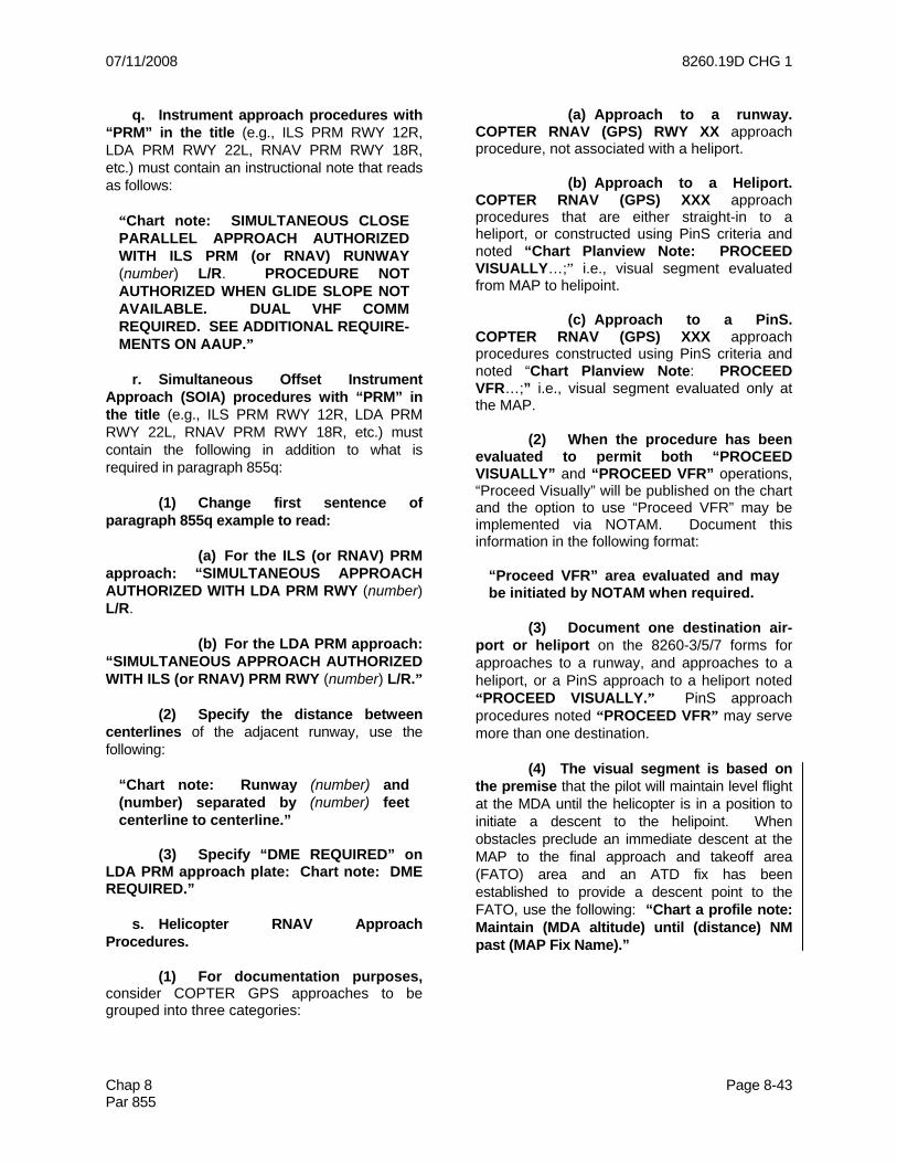
07/11/2008 8260.19D CHG 1
Chap 8 Page 8-43 Par 855
q. Instrument approach procedures with “PRM” in the title (e.g., ILS PRM RWY 12R, LDA PRM RWY 22L, RNAV PRM RWY 18R, etc.) must contain an instructional note that reads as follows:
“Chart note: SIMULTANEOUS CLOSE PARALLEL APPROACH AUTHORIZED WITH ILS PRM (or RNAV) RUNWAY (number) L/R. PROCEDURE NOT AUTHORIZED WHEN GLIDE SLOPE NOT AVAILABLE. DUAL VHF COMM REQUIRED. SEE ADDITIONAL REQUIRE-MENTS ON AAUP.”
r. Simultaneous Offset Instrument Approach (SOIA) procedures with “PRM” in the title (e.g., ILS PRM RWY 12R, LDA PRM RWY 22L, RNAV PRM RWY 18R, etc.) must contain the following in addition to what is required in paragraph 855q: (1) Change first sentence of paragraph 855q example to read: (a) For the ILS (or RNAV) PRM approach: “SIMULTANEOUS APPROACH AUTHORIZED WITH LDA PRM RWY (number) L/R. (b) For the LDA PRM approach: “SIMULTANEOUS APPROACH AUTHORIZED WITH ILS (or RNAV) PRM RWY (number) L/R.” (2) Specify the distance between centerlines of the adjacent runway, use the following:
“Chart note: Runway (number) and (number) separated by (number) feet centerline to centerline.”
(3) Specify “DME REQUIRED” on LDA PRM approach plate: Chart note: DME REQUIRED.” s. Helicopter RNAV Approach Procedures. (1) For documentation purposes, consider COPTER GPS approaches to be grouped into three categories:
(a) Approach to a runway. COPTER RNAV (GPS) RWY XX approach procedure, not associated with a heliport. (b) Approach to a Heliport. COPTER RNAV (GPS) XXX approach procedures that are either straight-in to a heliport, or constructed using PinS criteria and noted “Chart Planview Note: PROCEED VISUALLY…;” i.e., visual segment evaluated from MAP to helipoint. (c) Approach to a PinS. COPTER RNAV (GPS) XXX approach procedures constructed using PinS criteria and noted “Chart Planview Note: PROCEED VFR…;” i.e., visual segment evaluated only at the MAP. (2) When the procedure has been evaluated to permit both “PROCEED VISUALLY” and “PROCEED VFR” operations, “Proceed Visually” will be published on the chart and the option to use “Proceed VFR” may be implemented via NOTAM. Document this information in the following format:
“Proceed VFR” area evaluated and may be initiated by NOTAM when required.
(3) Document one destination air-port or heliport on the 8260-3/5/7 forms for approaches to a runway, and approaches to a heliport, or a PinS approach to a heliport noted “PROCEED VISUALLY.” PinS approach procedures noted “PROCEED VFR” may serve more than one destination. (4) The visual segment is based on the premise that the pilot will maintain level flight at the MDA until the helicopter is in a position to initiate a descent to the helipoint. When obstacles preclude an immediate descent at the MAP to the final approach and takeoff area (FATO) area and an ATD fix has been established to provide a descent point to the FATO, use the following: “Chart a profile note: Maintain (MDA altitude) until (distance) NM past (MAP Fix Name).”

8260.19D CHG 1 07/11/2008
Page 8-44 Chap 8 Par 856
856. MISSED APPROACH. a. General. The missed approach represents a critical phase of flight; therefore, the missed approach should be designed with a minimum of complexity. The instructions on the form must reflect the actual design. The straight-ahead missed approach is the most desirable. Each missed approach (except radar) must terminate at a clearance limit (fix or facility) and should terminate/connect to the en route structure. b. Clearance limit altitudes specified in missed approach instructions may be rounded to nearest 100-ft increments, provided Required Obstacle Clearance (ROC) is maintained. Other altitudes used in the missed approach should also use 100-ft increments. If this causes SIAP construction difficulties, use of 50-ft increments is the preferred alternative, with use of 20-ft increments the last resort. c. Missed Approach Point. On precision and LPV procedures the DA establishes the MAP. On nonprecision approach procedures, the MAP is established at a specified fix or at a specified distance from a fix or facility. On ILS/MLS procedures, the two MAPs should be coincidental. Additionally identify both MAPs - one for the full ILS/MLS (DA), and one for the LOC/AZ-only minimums (circling minimums if LOC/AZ minimums are not authorized). Identification of the LOC MAP will ensure the publication of a time/distance table on the associated approach chart. Specify distances to the nearest hundredth of a mile. (1) Form 8260-3. For the precision portion of the ILS procedure, the MAP is pre-printed on the form as: “ILS: at the DH.” For RNAV (GPS) enter as appropriate: “LPV: DA,” “LNAV/VNAV: DA,” “LNAV: RW18.” Designate the LOC and/or circling MAP as a specific distance in hundredths of a mile after a specified fix or facility or at a specified fix or facility. When LOC-only minimums are NOT authorized, the descent must be made on GS to circling MDA [see paragraph 854m(6)(e)]; change the preprinted term “LOC” to “Circling.” If DME is available, establish a DME fix in hundredths of a mile for the nonprecision MAP.
(2) Forms 8260-4/5/7. In the box, titled “MAP,” identify the missed approach point as “a distance after (or at) a specified fix or facility” as appropriate. Establish a DME fix in hundredths of a mile if DME is available. (3) RNAV. Do NOT list MAP coordinates for GPS or radial/DME for VOR/DME RNAV. Enter the name of the MAP WP as follows:
BONLI (MAP not at threshold) RW16L (MAP at threshold)
d. Missed Approach Instructions. Where possible, develop missed approach procedures (except radar) using the same type of navigation guidance utilized for the final approach segment.
Note: When using the word “direct” in the missed approach instructions, ensure that all categories of aircraft are evaluated; i.e., CAT A is not encompassed in CAT D missed approach area and vice versa. On RNAV procedures, use the term “Direct” ONLY when design incorporates a DF leg. .
Normally, a missed approach course/heading should be specified. If no course/heading is specified, the aircraft is expected to maintain the last established course/heading. Do NOT use the terminology “Climb runway heading” or “Climb straight ahead”; e.g., use Climb to 2800...” For turning missed approach procedures, specify the direction of turn; e.g., “Climb to 3,100 then left turn direct XYZ VOR/DME and hold.”
Note: To standardize and clarify altitudes and the meaning of “and” or “then” when used as connecting words between segments of the missed approach, “and” means a continuous climb to the stated altitude; “then” means the altitude condition must be reached at the point prior to the connecting word “then”, and either is maintained though the remaining missed approach or a second altitude will be stated.
(1) Where the missed approach course differs from the final course: “Climb to 2,800 via ABC R-180 to ABC VORTAC and hold.”

07/11/2008 8260.19D CHG 1
Chap 8 Page 8-45 Par 856
(2) When the missed approach point is also the missed approach holding fix and straight-ahead climb is not practical: “Climbing right turn to 2,500 in ABC VOR holding pattern.” In some cases, a straight-ahead climb or climb via a specified course/heading to an altitude, prior to returning to the holding fix, may be necessary for aircraft with larger turning radii. When this occurs, use the terminology in paragraph 856d(3) below. (3) When obstacles in a turning missed approach area require an initial straight-ahead climb: “Climb to 3,100 then climbing left turn to 4,000 direct ABC VOR and hold” or “Climb to 3,100 via ABC R-180 then climbing left turn to 4,000 direct ABC VOR and hold.” (4) When circumstances (terrain, obstructions, special use airspace, etc.) require an immediate turn: “Immediate climbing right turn to 4,000 direct ABC VOR” or “Immediate climbing right turn to 4,000 via heading 070 then direct ABC VOR and hold.”
Note: The word “immediate” is an emotion-laden word and should only be used when deemed absolutely necessary by the procedure designer and/or flight inspection pilot to enhance safety.
(5) Missed approach procedures requiring a turn of more than 15 degrees must specify an altitude that is at least 400 ft above the THRE/TDZE prior to commencing a turn. Round the resulting altitude to the next higher 100-ft increment: “Climb to 1,200 then climbing left turn to 3,100 via heading 070 and ABC R-167 to ABC VOR and hold.” Alternatively, a specific point (fix, waypoint, etc.) that will allow sufficient distance, at an assumed 200 ft/NM or specified gradient rate of climb to reach 400 ft above THRE/TDZE may be used: “Climb via ABC R- 090 to 9 DME, then climbing left turn to 5,000 direct XYZ VORTAC and hold.” See also paragraph 856b for rounding guidance. (6) If the procedure serves VOR as well as TACAN equipped aircraft, address TACAN requirements also: “Climb to 5,500 via
ABC R-111 then climbing right turn to 6,000 direct ABC VORTAC and hold (TACAN aircraft continue via ABC R-280 to CAROL 10 DME and hold W, LT, 100 inbound.)” (7) LOC courses are specified in compass points, and NDB courses as “courses to” or “bearings from:” “Climb to 3,000 via I-ABC Localizer NE course (030) and 350 course to DEF NDB and hold.” (8) When the missed approach requires no specific direction of turn: “Climb to 7,000 via ABC R-197 then direct ABC VOR and hold.” (9) RNAV missed approach instructions must convey the intended wording to the employed leg type. For example, the word “course” reflects a CF leg design; “track” reflects a TF leg design; “direct” indicates DF leg. However, when an RF leg is used, specify only the direction of the turn, (i.e., do not use “radius” as part of the instructions). EXAMPLES:
“Climb to 5,000 on track 080.22 to SANDY and track 104.56 to GINGR and hold” or, “Climbing left turn to 5,000 direct CHERL and hold” or “Climb on 098.32 course to JARID, then climbing right turn to 6,000 direct BOYCA and hold,” or “Climb to 4,000 on track 281.06 to FIKOG, right turn to WODVU, then track 011.23 to BTG VORTAC and hold” or Climb to 2,500 direct CRAZY then climbing right turn to 5,000 direct INSAN and direct LOONY and hold.
(10) RNAV (RNP) missed approach procedures require a note in the briefing strip that informs the pilot when the missed approach segment requires the use of RNP less than 1.0. Use: “Chart note: Missed approach requires RNP less than 1.0.”
Note: This note is required when the final approach segment (FAS) RNP is carried into the missed approach segment, i.e., missed approach does not splay at 15 degrees from the FAS RNP area.
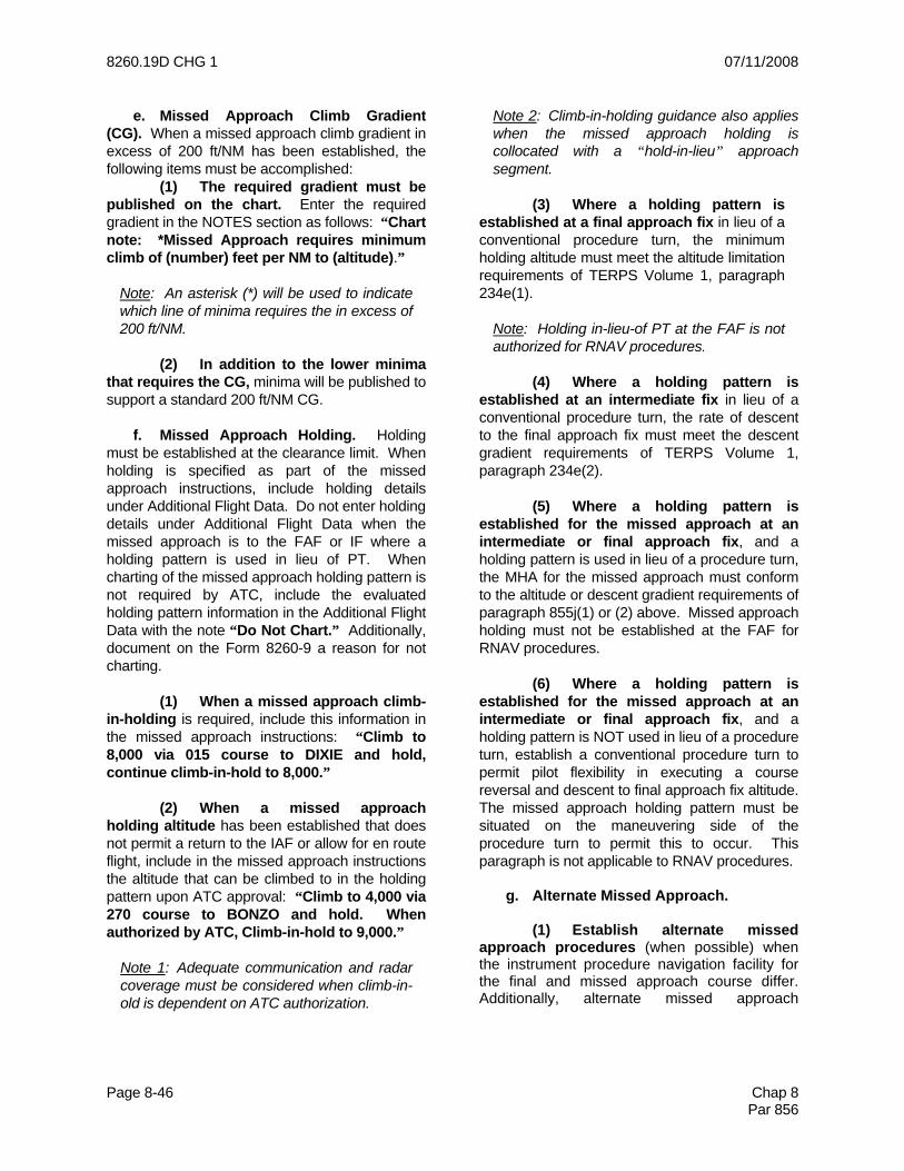
8260.19D CHG 1 07/11/2008
Page 8-46 Chap 8 Par 856
e. Missed Approach Climb Gradient (CG). When a missed approach climb gradient in excess of 200 ft/NM has been established, the following items must be accomplished: (1) The required gradient must be published on the chart. Enter the required gradient in the NOTES section as follows: “Chart note: *Missed Approach requires minimum climb of (number) feet per NM to (altitude).”
Note: An asterisk (*) will be used to indicate which line of minima requires the in excess of 200 ft/NM.
(2) In addition to the lower minima that requires the CG, minima will be published to support a standard 200 ft/NM CG. f. Missed Approach Holding. Holding must be established at the clearance limit. When holding is specified as part of the missed approach instructions, include holding details under Additional Flight Data. Do not enter holding details under Additional Flight Data when the missed approach is to the FAF or IF where a holding pattern is used in lieu of PT. When charting of the missed approach holding pattern is not required by ATC, include the evaluated holding pattern information in the Additional Flight Data with the note “Do Not Chart.” Additionally, document on the Form 8260-9 a reason for not charting. (1) When a missed approach climb-in-holding is required, include this information in the missed approach instructions: “Climb to 8,000 via 015 course to DIXIE and hold, continue climb-in-hold to 8,000.” (2) When a missed approach holding altitude has been established that does not permit a return to the IAF or allow for en route flight, include in the missed approach instructions the altitude that can be climbed to in the holding pattern upon ATC approval: “Climb to 4,000 via 270 course to BONZO and hold. When authorized by ATC, Climb-in-hold to 9,000.”
Note 1: Adequate communication and radar coverage must be considered when climb-in-old is dependent on ATC authorization.
Note 2: Climb-in-holding guidance also applies when the missed approach holding is collocated with a “hold-in-lieu” approach segment.
(3) Where a holding pattern is established at a final approach fix in lieu of a conventional procedure turn, the minimum holding altitude must meet the altitude limitation requirements of TERPS Volume 1, paragraph 234e(1).
Note: Holding in-lieu-of PT at the FAF is not authorized for RNAV procedures.
(4) Where a holding pattern is established at an intermediate fix in lieu of a conventional procedure turn, the rate of descent to the final approach fix must meet the descent gradient requirements of TERPS Volume 1, paragraph 234e(2). (5) Where a holding pattern is established for the missed approach at an intermediate or final approach fix, and a holding pattern is used in lieu of a procedure turn, the MHA for the missed approach must conform to the altitude or descent gradient requirements of paragraph 855j(1) or (2) above. Missed approach holding must not be established at the FAF for RNAV procedures. (6) Where a holding pattern is established for the missed approach at an intermediate or final approach fix, and a holding pattern is NOT used in lieu of a procedure turn, establish a conventional procedure turn to permit pilot flexibility in executing a course reversal and descent to final approach fix altitude. The missed approach holding pattern must be situated on the maneuvering side of the procedure turn to permit this to occur. This paragraph is not applicable to RNAV procedures. g. Alternate Missed Approach. (1) Establish alternate missed approach procedures (when possible) when the instrument procedure navigation facility for the final and missed approach course differ. Additionally, alternate missed approach

07/11/2008 8260.19D CHG 1
Chap 8 Page 8-47 Par 856
procedures may be established when requested by Air Traffic. Do not establish alternate missed approach instructions for RNAV procedures. Alternate missed approach instructions must not be charted. When alternate missed approach instructions are established, the words: “… or as directed by ATC” must immediately follow the primary missed approach instructions. Then document the alternate missed approach procedure as a separate entry. EXAMPLE:
CLIMB TO 3,000 THEN TURN RIGHT DIRECT XUB VOR AND HOLD, OR AS DIRECTED BY ATC. ALTERNATE MA: CLIMB TO 3,000 THEN TURN RIGHT DIRECT DD LOM AND HOLD.
(2) The alternate missed approach termination facility/fix and holding pattern must be charted in the planview. If the alternate missed approach termination facility/fix and holding pattern is not already used in the procedure, then add a note in Additional Flight Data. EXAMPLES:
Chart in planview: (facility/fix name). Chart in planview: ALTERNATE MA HOLDING, HOLD SW DD LOM, RT, 051 INBOUND.
h. NAVAID Outages. When temporary NAVAID outages (planned or unplanned) prohibit the use of the primary missed approach for a procedure, the NFPO has the responsibility to ensure an IFR missed approach procedure is published, either on the chart or by NOTAM in the event of lost communications. This does not preclude Air Traffic from issuing alternate climb-out instructions. 857. ADDITIONAL FLIGHT DATA. When additional information or data is essential to clarify the charting of a procedure or when the procedures specialist wants information charted,
but does not want it to appear on the chart as a note, the necessary information/data must be entered in the Additional Flight Data section. Preface specific items to be charted with the term “Chart.” Specific instructions to chart data must be held to a minimum [see also paragraphs 804b and 856f].
Note: Do NOT document takeoff obstacles on the Form 8260-9 or in Additional Flight Data.
a. If sufficient space is not available on the form for all necessary data, it may be continued in the Notes section or on Form 8260-10. When necessary to use Form 8260-10, state: “See FAA Form 8260-10.” b. Items such as holding information, restricted area data, final approach course alignment, etc., must be retained when amending a procedure. c. Enter Holding Instuctions as follows: (1) When primary missed approach instructions provide for holding, enter Additional Flight Data as follows: “Hold SE, RT, 313.09 inbound.” See paragraph 856f. (2) Where alternate missed approach holding is established, enter the description as described in paragraph 856g(2). (3) Where unplanned holding is provided at the alternate missed approach clearance limit, enter the following: “Chart alternate MA clearance limit, PUGGY (int, fix, DME, etc.).” (4) Where arrival holding is operationally advantageous, enter: “Chart arrival holding at PUGGY: Hold SE, RT, 313.09 inbound, 4,000.” d. The nonprecision controlling obstacle in the primary and/or secondary area of the FAS must be shown as the FAS Obstacle. In the event a stepdown fix is used in the final approach segment, the controlling obstacle between the

8260.19D CHG 1 07/11/2008
Page 8-48 Chap 8 Par 857
stepdown fix and the runway must be shown as the FAS obstacle. Designate the obstacle elevation in mean sea level (MSL) and location to the nearest second. List obstacle as:
“Chart FAS Obst: 317 Tower 364227N/ 0891523W.”
Note: When the FAS Obstacle is an AAO, do not chart it. Enter the data as follows: “FAS Obst: 529 AAO 365029N/0871234W”.
e. To identify certain significant obstacles, other than AAOs, in or near the instrument approach area, include locations and MSL heights under additional flight data. If, in the opinion of the procedures specialist, these obstacles could be critical to flight safety, they should be prefaced by the word “Chart.” However, if the data is being furnished only as information, it must NOT be prefaced by the word “Chart.” Charting agencies will chart any item marked “Chart.” Any item listed without indicating “Chart” will be reviewed by the charting agencies and will be charted if it meets their charting specifications. List obstacles as follows: “Chart 2674 antenna 372219N/0941657W” or “2674 antenna 372219N/0941657W.” f. Obstacles close to a final approach or stepdown fix considered under TERPS Volume 1, paragraph 289, must be accomplished as follows: (1) When paragraph 289 is applied to multiple obstacles, document only the highest obstacle in the 7:1 area. (2) List the obstacle under Additional Flight Data as: “Chart 374 antenna 352416N/ 0881253W.” Do not chart if the obstacle is an AAO; document as noted in subparagraph d Note. Do NOT identify it as a “paragraph 289 obstacle.” Additionally, make the following entry in the Remarks section of the Form 8260-9: “TERPS paragraph 289 applied to 374 antenna 352416N/0881253W.” g. Installed visual aids will be shown on the aerodrome sketch. NASR is the source for this information, which will be obtained and
maintained by NACO for TPP airport sketch charting purposes. Changes are published in the National Flight Data Digest (NFDD). h. Final approach course alignment, when required, is specified in Additional Flight Data as follows: (1) For offset vertically guided (ILS, MLS, LDA w/GS, RNP, LPV, and LNAV/VNAV) approaches document the amount of offset of the final approach course relative to the runway centerline extended as follows:
“Chart Planview Note: LOC offset X.XX degrees” or “Chart Planview Note: Final Approach Course offset X.XX degrees.” Note: Compute the amount of offset to the nearest hundredth of a degree (0.01) by measuring the difference between the true bearing of the FAC and the landing runway true bearing. True bearing values are as recorded in the Facility Data Record.
(2) For straight-in and offset nonprecision (e.g., LDA, LNAV, VOR, etc.) approaches, document the final approach course alignment relative to the runway centerline at threshold, as follows:
“FAC crosses RWY C/L extended 3,180 from THLD”; or “FAC 450L of RWY C/L extended 3,000 from THLD.” (Left or right as used in the latter case is as viewed by the pilot.)
(3) For circling approaches, document the final approach course alignment relative to the on-airport facility, or to the Airport Reference Point. If the facility is off-airport, enter the point where the FAC crosses the landing surface as follows:
“FAC crosses intersection of RWYs 9-27 and 18-36” or “FAC crosses mid point of RWY 13-31.”

07/11/2008 8260.19D CHG 1
Chap 8 Page 8-49 Par 857
i. When a flight check value is used for the final approach course instead of the plotted radial/course/bearing, add the following: “FAC is a flight check value.” See also para-graph 852c(1)(c). j. When a procedure planview area encompasses Special Use Airspace (SUA), use the following note as deemed necessary: “Chart P-56.” k. When simultaneous approaches are authorized, each approach must include an entry requiring the depiction of the adjacent localizer. Enter the data as follows: “Chart LOC RWY 27R.” l. RNAV Data. Publish the following data for RNAV procedures: (1) For VOR/DME RNAV, enter the reference facility elevation; e.g., “Reference facility elevation XYZ VORTAC 1160.” (2) RNP, LPV, and LNAV/VNAV. Identify the distance to threshold from the lowest DA: “Distance to THLD from 354 HAT: 0.93 NM.” (3) For LPV and LNAV/VNAV. Enter the Route Type(s), Route Type Qualifier(s), WAAS Channel Number, and Reference Path Identifier (Approach ID) using the following example [see paragraph 499]. For LNAV/VNAV procedures only, there will not be a WAAS Channel Number or Reference Path ID. For agencies providing a complete ARINC packet record on Form 8260-10, Route Type(s) and Route Type Qualifier(s) entries are not required.
ROUTE TYPE: A, R ROUTE TYPE QUALIFIER 1: J ROUTE TYPE QUALIFIER 2: S WAAS (or LAAS) CHANNEL #43210 REFERENCE PATH ID: W (or G) 17A
(4) For LNAV/VNAV. Enter “Chart WAAS Symbol” when it has been determined that a WAAS signal may be unreliable for vertical navigation use.
(5) For WAAS/LAAS procedures, document the Height Above Ellipsoid (HAE) used in calculations. See paragraph 275c. m. ASR and/or PAR Approach Availability. When ASR and/or PAR approaches are published for the airport, enter the following: “Chart: ASR” or “Chart: ASR/PAR” – as appropriate. n. Magnetic Variation. Except as provided in paragraph 803, enter the magnetic variation value upon which the procedure design and documentation is based. (1) For non-RNAV SIAPs, enter the officially assigned variation value of the facility providing final approach course guidance. (2) For VOR/DME RNAV SIAPs, enter the officially assigned variation value of the reference facility. (3) For all other RNAV SIAPs, enter the officially assigned variation value of the airport served by the SIAP. o. Enter the Epoch Year of the variation value as designated by the NFPO [see para-graph 221c(1)]. Enter this value in 4 digits:
EPOCH YEAR: 2000 p. For COPTER PinS procedures that serve more than one landing area and are noted to “proceed VFR” or Special procedures that have had a visual assessment accomplished and state “Proceed Visually,” list available landing areas, facility identifier, landing area elevations, the courses in hundredths of a degree, and distances from the MAP in hundredths of a mile as follows:
East 34th Street Heliport, 6N5, 10, 257.02/13.81 Port Authority-Downtown-Manhattan Wall Street Heliport, JRB, 7, 246.03/15.51
q. For COPTER PinS procedures that have obstacle penetrations in the VFR Transition Area surface evaluation, enter:

8260.19D CHG 1 07/11/2008
Page 8-50 Chap 8 Par 857
Obstacles Penetrate PinS VFR Transition Area - Training Required.
r. Where a VDP is established on a SIAP, identify the location of the VDP as follows: (1) Non RNAV: Specify the VDP DME fix and distance to threshold.
Chart VDP at _____DME; Distance VDP to THLD_____miles. Note: If the VDP is for a localizer procedure on an “ILS or LOC” approach plate, indicate the VDP as applicable to LOC Only. Chart VDP at _____DME*; Distance VDP to THLD_____miles. *LOC only
(2) RNAV and LNAV: Indicate the VDP distance to MAP.
Chart VDP at miles to RW16. Chart VDP at miles to SUSIE.
(3) RNAV/VNAV: Indicate the VDP as applicable to LNAV only. Chart VDP at miles to RW16* * LNAV only. s. For MLS, enter the following data: (1) Limits of coverage; e.g., 300 M to 060 M (2) Height above EL antenna for all fixes from FAF to MAP: PFAF(1590), TP(1496), RP(1183), DH(194), RWY (44). (3) Describe the curved path including radius and direction of turn, course before and after the turn, along-track distance from each fix:
1.25 NM arc to RP RT 351 deg to 133 deg 6.58 ATD from PFAF 6.33 ATD from TP 0.50 ATD from DA
t. Enter charting instructions for maximum or mandatory altitudes; e.g., “Chart mandatory 5,000 at DAVID.”
Note: Maximum or mandatory altitudes should be avoided where possible, especially in the final approach segment. Maximum or mandatory altitudes in the final approach segment must be coordinated through AFS-460 prior to forwarding for publication.
u. Vertical Descent Angle (VDA)/TCH.
(1) For nonprecision SIAPs (except RNAV with published VNAV minimums), enter the descent angle for the final approach, and the appropriate TCH: NIXON to RW15: 3.26/55. Where the VDA values are not coincident with published VGSI values, see paragraph 855n. (2) For COPTER procedures, except those annotated “proceed VFR…” enter the visual descent angle (to the hundredth of a degree) from the specified descent point (MAP or ATD after MAP) to a specified hover height (20-ft maximum). Data entry format: (MAP Name) TO HELIPORT: 7.30/5 ft HOVER or 0.2 NM after (MAP Name) TO HELIPORT: 7.50/20 ft HOVER.
Note: Except for COPTER procedures to runways, do not publish vertical descent angle data from FAF to MAP.
v. Computer Navigation Fixes (CNF): Enter charting instructions for CNFs; e.g., “Chart (ABCDE) at intersection of DR leg and intermediate course.” w. Arc IAFs: Enter the radial that defines the beginning of the arc initial segment; e.g., “Chart ABC R-060 at WERNR.” 858. LOWER BLOCKS. a. CITY AND STATE. Enter associated city and state name as derived from NASR. Use the official two-letter state abbreviations. b. ELEVATION/THRE/TDZE/AIRPORT NAME.

07/11/2008 8260.19D CHG 1
Chap 8 Page 8-51 Par 858
(1) Enter the official airport/heliport name and airport/heliport elevation as derived from NASR. For COPTER PinS procedures noted to “proceed VFR” to the landing site, revise “Elevation” and “THRE/TDZE,” and enter “Surface Elevation.” Then enter the highest terrain/surface elevation within a 5,200-ft radius of the MAP. For multiple COPTER point-in-space SIAPs, enter “Various Heliports.”
Note: Paragraph 857p requires each heliport to be identified in the Additional Flight Data Block.
(2) Enter Threshold Elevation (THRE) or Touchdown Zone Elevation (TDZE) [as stated in the AMIS/IAPA database] for the runway designated in the procedure title. Enter the sidestep runway and THRE/TDZE, if applicable, below the first entry; e.g.,:
THRE: 28L 2854 THRE: 28R 2858
Leave the THRE/TDZE blank if straight-in minimums are not authorized or if the procedure is a COPTER PinS procedure [see paragraph 857p]. c. FACILITY IDENTIFIER. Enter facility identification. On procedures predicated on proposed facilities and when an identification has not been assigned, leave this space blank and NFDC will enter the identification. For VOR/DME RNAV procedures, enter the identification of the SIAP reference facility. For RNAV or FMS procedures, insert RNAV or FMS as applicable. d. PROCEDURE NO. Enter procedure identification as determined by TERPS Volume 1, chapter 1, section 6, and paragraph 802 of this order. (1) When DME is required for the final approach, include “/DME” as part of the identification; e.g., VOR/DME, LOC/DME, LDA/ DME, NDB/DME. (2) For RNAV (or FMS for which GPS is required) procedures, use RNAV (GPS) RWY 22.
(3) When a procedure also contains CAT II/III minima, include the name of the additional procedure(s). EXAMPLE:
ILS or LOC/DME RWY xx, Orig ILS RWY xx (CAT II) ILS RWY xx (CAT III)
(4) When an ILS/MLS procedure contains “PRM” in the title (e.g., ILS PRM RWY 30L), on the line below it, include the text “Simultaneous Close Parallel” in parenthesis. EXAMPLE:
ILS PRM RWY 30L (SIMULTANEOUS CLOSE PARALLEL)
e. AMDT NO.: Enter “ORIG” or “AMDT” with the applicable amendment number/letter. The amendment number must be advanced whenever the procedure is revised. The type of revision will determine whether an amendment may be made or whether the procedure must be canceled and an original established. (1) Cancellation of an existing procedure and establishment of an original procedure is required when: (a) The Part 97 subpart changes as a result of a change in equipment required to fly the procedure; e.g., “LOC” to “ILS or LOC;” “ILS” to “LOC;” etc. [see paragraph 802b]. (b) Procedure ID changed from VOR-A to VOR-B, etc. (c) The facility providing final course guidance is relocated and the relocation changes the published final approach course. (d) The reference facility is changed to another facility on a VOR/DME RNAV procedure. (e) Straight-in minimums are added or deleted which require change to procedure ID; e.g., NDB RWY 28 to NDB-A.

8260.19D CHG 1 07/11/2008
Page 8-52 Chap 8 Par 858
(f) Development or mainte-nance responsibility of a Special IAP is transferred [see paragraph 441b(10)]. (2) Amendment of a procedure is required when: *(a) The airport name is changed. *(b) The associated city/state is changed. *(c) The identification of the facility providing final approach course guidance is changed. (d) Equipment is added to or deleted from the procedure which does NOT change the procedure ID; e.g., adding “DME Required” Note. (e) Procedure ID changes from “VOR/DME” to “VOR/DME or TACAN;” “ILS” to “ILS or LOC/DME." *(f) The runway designation is changed due to renumbering of the runways. (g) Any published fix (name or makeup), course, or altitude is changed. (h) Any published distance is changed which: 1 Requires a change to the Time/Distance Table. 2 Is greater than 0.5 NM for distances outside the FAF, or greater than 0.1 NM for distances inside the FAF. (i) Any minimums change. (j) Airport elevation is changed where ceiling and/or visibility is affected. (k) Frequencies are changed in notes on the Forms 8260-3/4/5/7, or military equivalent. (l) Lighting changes occur and this affects published visibility.
(m) L or R designation removed from title; e.g., VOR/DME RWY 18L/R changed to VOR/DME RWY 18L. (3) A delayed amendment, not requiring immediate amendment action, BUT which must be processed at the next opportunity, is required when: (a) The airport elevation/TDZE is changed BUT published ceiling and/or visibility is NOT affected. (b) Safety of flight is no factor. (c) Any published distance is changed which is less than or equal to 0.5 NM for distances outside the FAF, or less than or equal to 0.1 NM for distances inside the FAF. *(d) Marker Beacons that have been identified for charting have been decommissioned. (4) No amendment is required when: (a) Frequencies are changed which were NOT entered in notes on the Forms 8260-3/4/5/7, or military equivalent. (b) Names of airports mentioned in the “Notes” block of the 8260-series form are changed; e.g., “Use Batesville/Batesville Regional Altimeter setting.” (c) Names and identifiers of facilities are changed, including those mentioned in the “Additional Flight Data” and “Missed Approach” blocks of the 8260-series form. (d) Obstacles, names of secondary airports shown in the Planview, lighting and communications items included in the “Additional Flight Data” block of the 8260-series form. (e) Lighting changes occur which do NOT affect published visibility. (f) Fix coordinates are changed, which do not require a change to the procedure chart [see paragraph 858e(2)(h)].

07/11/2008 8260.19D CHG 1
Chap 8 Page 8-53 Par 858
(5) The NACO may change those items in subparagraphs (2) and (3) above that are identified with an asterisk (*) upon publication in the NFDD as follows: (a) Procedure amendment(s) are required; therefore, changes must be coordinated with the NFPO so that a formal amendment to the SIAP may be made as soon as possible. (b) Associated city/state changes must be coordinated to become effective on a 56-day AIRAC date. (c) Other changes need not be concurrent with a procedure amendment; however, the amendment must occur no later than the charting cycle following the change. (d) Procedure titles and minima lines may also be revised when runway designations are changed due to re-numbering. (e) Decommissioned Marker Beacons may be deleted from chart publication. f. EFFECTIVE DATE. The effective date of the procedure will normally be entered by NFDC. The only time the effective date must be entered by the NFPO is when a specific effective date is required; e.g., a facility Mag Var rotation [see also paragraph 811c(4)]. Due to the heavy workload associated with the 56-day airspace charting dates, NFDC will normally schedule routine procedure amendments for charting dates commensurate with NFDC and NACO workload. When an effective date is required which is earlier than can be routinely assigned by NFDC, the NFPO and Aeronautical Information Management Group (AIMG) must coordinate to determine the appropriate course of action to expedite publication.
(1) Original Procedures. The effective date of original procedures must be in accordance with Order 8260.26; except that the 28-day change notice will not be published for Alaskan or Pacific procedures or for procedures that require en route charting changes. (2) Routine Amendments. Routine amendments to SIAPs are made effective based on the time NFDC requires to process and distribute the SIAP, plus the time required for charting and distribution to subscribers. Normally this time period is nine weeks after receipt of the SIAP in NFDC. Procedures that contain an en route fix name change or re-identification must be made effective on the 56-day cycle charting date, to coincide with the publication of en route charts. Amendments to procedures pending flight inspection must be held by the NFPO until the flight inspection is complete; then forwarded as “routine.” g. SUP:/AMDT:/DATED: (1) SUP: Enter the identification of the superseded procedure if the name has changed. (2) AMDT: If the procedure is original, enter “NONE;” otherwise, enter “ORIG” or amendment number as appropriate. (3) DATED: If the procedure is original, leave blank; otherwise, enter previous amendment date. 859. RESERVED.

8260.19D CHG 1 07/11/2008
Page 8-54 Chap 8 Par 860
SECTION 8. STANDARD INSTRUMENT APPROACH PROCEDURE DATA RECORD, FAA FORM 8260-9
860. PREPARATION OF FAA FORM 8260-9. The Standard Instrument Approach Procedure Data Record, FAA Form 8260-9, must be prepared in accordance with the instructions below for each instrument approach procedure developed by the NFPO or non-Federal procedure developers. The form is designed as a supporting document for the approach procedure. It serves as a checklist for the procedures specialist, as a technical reference for the flight inspector, and provides a permanent record of data currently available at the time of procedural development. a. Part A: Obstruction Data. (1) Block 1: (a) App. Segment. Identify each Feeder, Initial, Intermediate, and Final segment, and stepdown fixes therein. If the IF is also an initial approach fix, identify the IF with “(IF/IAF)” in the “From” column. For precision approaches which have separate intermediate and final segments for the precision and nonprecision approaches, identify all: Intermediate: ILS and Intermediate: LOC; Final: ILS and Final: LOC. (b) From/To. Enter segment start/end points, including stepdown segments, as listed in the Terminal Routes section of Forms 8260-3/4/5/7. Enter the PT completion distance in the “From” column opposite the intermediate or final segment, as appropriate. Enter RWXXX in the “To” column for the final/stepdown segments. Enter “GP Intcp” (or PFAF name if established) in the “From” column and “RWXXX” in the “To” column for vertically guided procedures (even though the missed approach begins at the DA). Enter the Hold-in-Lieu-of-PT facility/fix in the “From” column, and the holding template number from the controlling obstacle information of the Form 8260-2 for the Hold-In-Lieu of PT facility/fix in the “To” column.
(c) Obstruction. Select the con-trolling obstruction as directed by chapter 2, section 11, Obstacle Data. Enter controlling obstruction type (tower, trees, terrain, AAO, etc.) and state obstacle number, if available, within each approach segment on one line. Enter segment (except final) highest terrain data on the next line. Number obstruction column entries sequentially as they appear on the form in blocks 1 to 4. For obstructions or terrain common to other segments, enter only the number from the “obstruction” column for each subsequent repetition, leaving the “coordinates” column blank, but completing remaining column entries. (d) Coordinates. Enter coordi-nates in degrees, minutes, and seconds to the hundredth; e.g., 411532.01N/0943028.09W. (e) Elev MSL. 1 Enter the controlling obstacle/terrain MSL elevation followed in parentheses by the appropriate accuracy code. Any required altitude adjustment due to accuracy code application is shown in the “Alt. Adj.” column. 2 Enter the highest terrain elevation used for airspace evaluation to the nearest foot, followed in parentheses by that value rounded to the nearest 100 ft; e.g., 249 (200). See paragraph 507b. Do NOT assign an accuracy code to terrain used for airspace evaluation. (f) ROC. Enter required obstruction clearance (ROC) for each segment. For precision, LPV, and LDA with glide slope approaches where the OCS is clear, enter “ASC” (all surfaces clear). For RNP and Baro-VNAV procedures where obstacles allow a 250-ft HATh, enter “ASC.” When the DA is determined by an obstacle within the required ASBL 250-ft ROC area, enter “PDA.” Where obstacle slope penetrations cause DA adjustment, enter the slope penetrated; e.g.,

07/11/2008 8260.19D CHG 1
Chap 8 Page 8-55 Par 860
34:1. Where obstacles require a glide slope higher than 3 degrees, enter the slope supporting the higher glide slope; e.g., 31.9:1 (for a 3.2 degree glide slope). Document obstacle penetrations per paragraph 860a(1)(c). (g) Alt. Adj. Do NOT enter additives required for rounding purposes. State only the reason for and amount of adjustment, rounded to the next higher foot [see paragraphs 272a and b]. The following codes should be used: RA - remote altimeter; AS - airspace; AT -air traffic; AC - accuracy code; CA - cardinal altitude; SI - straight-in minimums; XL - excessive length of final; PR - precipitous terrain; HAA - circling minimum HAA; MA - missed approach; MT – mountainous terrain; PT procedure turn; DG - descent gradient; GS - glide slope; MEA - minimum en route altitude; MAH - missed approach hold; SA - secondary area (also X/Y surfaces, transition areas). Enter the adjustment amount for all codes except SI and HAA. Use XP to refer to the remarks section for items not covered in this paragraph. For example: AC50, SA-27, AS1500, etc. If necessary explain the code used in Part C - REMARKS. For precision or APV approaches, where obstacles require a glide slope higher than 3 degrees, enter GS but exclude the amount of adjustment. (h) Min. Alt. The obstruction elevation + ROC + altitude adjustment = minimum altitude (computed); OR, high terrain elevation + airspace adjustment = minimum altitude (computed). Enter the appropriately rounded value. Make entries on the obstruction line as well as the airspace evaluation line. When possible, separate sets of segment entries with a blank line. The segment minimum altitude to be published must be the higher rounded value, and must match the respective altitudes shown on the corresponding Forms 8260-3/4/5/7. For part-time remote altimeters, make entries in the final/ stepdown “Alt. Adj.” and “Min. Alt.” columns on a separate line just below the entries for full-time altimeter. The minimum altitude values for non-precision final/stepdown and circling must be rounded to the next higher 20-ft increment. For precision or APV approaches, enter DA and HATh/HAT values separated by a “/”; e.g., 1718/200, 1640/383, etc.
(2) Block 2: Identify the procedure turn fix/facility under the “From” column. Enter the procedure turn completion distance under the “To” column. If a procedure turn is not authorized, enter “NA” under the “from” column. For procedure turn entry zone obstacles, enter “Entry Zone” in the space above “Procedure Turn” as appropriate; leave “from” and “to” blocks blank. Allow two lines for obstruction/airspace evaluation entries. (3) Block 3: (a) Identify the missed approach point (MAP). For precision or APV approaches, list both precision/APV and nonprecision MAPs (if not collocated), listing precision first. Enter the elevation of the missed approach surface (HMAS) at the MAP: enter the HMAS for precision or APV first, then for nonprecision. Separate both figures with a “/.” For the LOC portion of an ILS with a stepdown, enter the surface elevation associated with the lowest MDA. Elaborate in REMARKS as necessary. (b) Specify the clearance limit under the “to” column. (c) Document the controlling obstacle [see paragraph 274b]; including 40:1 surface penetrator and highest 1,000-ft level surface, by obstacle type, coordinates and elevation. Document highest terrain in the level surface primary area, as well as adjustments, etc. Specify the controlling obstruction, coordinates, and elevation where a climb gradient is required for ILS CAT II or III. (d) Enter “ASC” in the “ROC” column. Enter the clearance limit altitude. Elaborate in REMARKS, if necessary. (4) Block 4: Enter the circling data for each category of aircraft authorized by the procedure. The required height above the airport (HAA), the straight-in MDA, or the circling ROC may determine the minimum circling altitude. When the minimum altitude has been established, enter the resulting HAA in the “actual” block. If two HAAs are available, enter both HAAs

8260.19D CHG 1 07/11/2008
Page 8-56 Chap 8 Par 860
separated by a “/.” Enter controlling obstacle type and NACO obstacle number, if appropriate. Enter controlling obstacle coordinates to the hundredth of a second. Enter controlling obstacle MSL elevation followed in parentheses by theappropriate accuracy code. Enter ROC to the nearest foot. When HAA controls the circling minimum altitude, enter “HAA” in the “ALT. ADJUST.” column; when the straight-in MDA controls the circling minimum altitude, enter “SI.” Enter other adjustment codes and amounts as appropriate [see Block 1, paragraph g]. Enter only the published minimum altitudes to the next higher 20-ft increment. If use of a remote altimeter requires a higher minimum circling altitude, enter both values separated by a “/” (or only the remote altimeter value, if applicable). (5) Block 5: Identify the NAVAID or fix used as the MSA center point, the type of obstructions and their location by reference to bearing (magnetic) and distance (nearest 0.1 NM) from the center point. Enter the controlling obstruction type (tower, trees, etc.) for each sector. Enter the MSL elevation of the respective controlling obstacle to the nearest foot followed in parentheses by the appropriate accuracy code. Enter the resulting MSA in the appropriate block in hundreds of feet. If a “common safe altitude” is established, define only one sector (360 degrees - 360 degrees) and only the one controlling obstacle. Enter appropriate data for RNAV procedures incorporating a TAA with an MSA sector established in lieu of a TAA sector. Leave blank for RNAV procedures incorporating a TAA. (6) City and State; Airport and Elevation; Facility Procedure; Procedure and Amendment No.; Region: Enter city/state, airport name and elevation as on Forms 8260-3/4/5/7. Enter facility identification and type; for VOR/DME RNAV procedures, enter the identification of the SIAP reference facility. For RNAV or FMS procedures, insert RNAV or FMS as applicable. Enter the procedure name if the procedure is an original, enter “ORIG” or if an amendment, enter “AMDT” with the applicable number. Enter the three-letter code for the FAA region responsible for the SIAP. b. Part B: Supplemental Data.
(1) Block 1: Identify the facility or facilities providing approach control and terminal service to the airport. If no full-time or part-time control tower, include the associated FSS. Flight inspection reports are the source for the primary frequency bands in which satisfactory communi-cations are provided. For clarity, facility identifica-tion should agree with those used in the Airport/Facility Directory (AFD). (2) Block 2: Identify the weather reporting service(s) used for the procedure. Check “FAA,” “NWS,” and/or “A/C” as appropriate for weather offices used for the procedure. “A/C” indicates an air carrier with approved weather reporting service. Enter automatic weather reporting systems used in “Other.” Include level for AWOS. Enter the location by ICAO airport identifier for the weather source(s). Hrs Optn: leave blank. For agencies with access to Aviation System Standards Information System (AVNIS), leave Block 2 blank. (3) Block 3: Identify by ICAO airport identifier the altimeter setting source (or sources separated by a “/”). If an altimeter setting is derived from a remote source, indicate the distance to 0.01 NM. Enter the number of clock hours of remote service. If the remote altimeter setting is used for backup purposes, enter the word “Backup” in the Hours Remote Operation block. Enter the resulting altitude adjustment (ROC increase) value rounded to the next higher whole foot increment. This value is used in the “ALT. ADJ.” Column in Part A, as appropriate. For agencies with access to Aviation System Standards Information System (AVNIS), leave Block 3 blank. Enter in Part C, REMARKS, whether pressure patterns are the same, or not, the ICAO Airport Identifiers and Field Elevations when pressure patterns are the same, or High and Low Terrain values when pressure patterns are not the same, and the raw remote altimeter adjustment. Example:
RASS pressure patterns same KOMA 984, KMLE 1050 RA = 36.3

07/11/2008 8260.19D CHG 1
Chap 8 Page 8-57 Par 860
RASS pressure patterns not the same High Terrain 1634, Low Terrain 323 RA = 210.6
(4) Block 4: Identify the primary NAVAID (facility providing final approach guidance) and the location providing CAT 1 monitoring service. Enter the number of hours per day for CAT 1 monitoring service, and CAT 3 monitoring service at part-time monitoring points. Secondary blocks, leave blank. For GPS or RNAV or non-VOR/DME RNAV, leave blank. For VOR/DME RNAV, enter the Reference Facility 3-letter ID. For agencies with access to AVNIS, leave Block 4 blank. (5) Block 5: Indicate the available approach, runway, and visual glide slope indicator (VGSI) lighting used for the procedure. Complete preprinted entries on computer generated form. Enter VGSI types, i.e., VASI, PAPI, etc, in “Other.” Enter “(PCL)” in the respective block when pilot controlled lights are available. For agencies with access to AVNIS, leave Block 5 blank. (6) Block 6: List the runways with serviceable runway markings. Place “BSC” data on Runway line, “PIR” data on “All Weather” line, and “NPI” data on “Instrument” line. Place non-standard data in REMARKS. For agencies with access to AVNIS, leave Block 6 blank. (7) Block 7: List runway visual range (RVR) systems for the straight-in runway served by the procedure. Enter midfield RVR data on “Midfield” line. For agencies with access to AVNIS, leave Block 7 blank. (8) Block 8: Provide GS/GP information as indicated for all precision and APV procedures to the following accuracy: GS/GP angle – nearest .01 degree; distance THLD to GS/GP Ant – nearest foot; elevation RWY THLD and GS/GP Ant – nearest 0.1 ft; TCH – nearest 0.1 ft. These values must agree with the approved database. For agencies with access to AVNIS, leave Block 8 blank.
(9) Block 9: Identify the desired approach course aiming point as determined by the procedure construction. Normally this will be the runway threshold or a point on the runway centerline extended at a specified distance from the threshold. Check both blocks on any precision or APV approach, or where the FAC is directly aligned to the runway threshold. For distances, from thresholds between 3,000 ft and 5,200 ft, enter the specific value. For those final approaches that parallel the runway centerline extended or intersects the centerline more than 5,200 ft from the threshold, specify the distance between the FAC and the RCL extended at a point 3,000 ft from the LTP measured perpendicular to the RCL. For circling or point-in-space alignment, explain in REMARKS. (10) Block 10: List all waivers by stating the Order number, paragraph, and a brief description of the waiver in the following format:
Order 8260.3B, Volume 1, paragraph 282a and Volume 3, paragraph 2.9.1; DME signal source angular divergence exceeds maximum allowed.
c. Part C: Remarks. Use this space to amplify previous entries (state associated block number for reference), or to record essential data not considered elsewhere on the form. See also paragraphs 431, 852c(1)(c), and 857f. (1) Document TERPS, Volume 1, paragraph 251 surface penetrations. Document 20:1 penetrations first, followed by 34:1 penetrations as applicable. For an obstacle that penetrates the 20:1 surface, do not repeat the documentation process for the 34:1 surface (i.e., 20:1 penetrations automatically penetrate the 34:1 surface). Include the obstacle MSL elevation, obstacle type and ID (if applicable), coordinates, and amount of penetration to the hundredth of a foot. Use standard entry: TERPS, Volume 1, paragraph 251 penetrations: 20:1 5345 TREE (KSUN0092) 432931.65N/1141713.21W (43.57) 5342 TREE (KSUNT037) 432930.08N/1141710.91W (30.03)

8260.19D CHG 1 07/11/2008
Page 8-58 Chap 8 Par 860
34:1 5337 TREE (KSUN0081) 432927.26N/1141702.79W (27.89)
Note: For RNAV (RNP) procedures, include the horizontal/vertical obstacle accuracy values. The amount of penetration includes obstacle accuracy.
20:1 5345 TREE (KSUN0092) (20/2) 432931.65N/1141713.21W (46.07) 5342 TREE (KSUNT037) (50/20) 432930.08N/1141710.91W (51.19) 34:1 5337 TREE (KSUN0081) (20/2) 432927.26N/1141702.79W (30.51) (2) State the effect, if any, of waivers to published minimums. (3) For VOR/DME RNAV SIAPs, enter the MA fix XTRK error. (4) For RNAV SIAPs, state the type and coordinates of the obstacle penetrating the RNAV obstacle slope. (5) Enter the amount of threshold displacement, if any. (6) Enter airspace date required by paragraph 507k. Carry this information forward until amended. Alternatively, this information may be entered on any acceptable format for provision of airspace data to ATC. This form must document ALL the data requirements of paragraph 507k. (7) When flight inspection deter-mines TCH in accordance with Order 8260.3B CHG 19, enter: “Flight Check RDH ______ft, (Order 8260.3B CHG 19).” Substitute ARDH for RDH if appropriate. (8) When flight inspection establishes a final FAC other than the plotted magnetic course, enter:
“Plotted FAC is 0.87.43 M.” “Electronic flight inspected FAC is 089 M.”
(9) For RNAV (GPS and RNP) Baro-VNAV procedures, enter Critical Temperature computations if other than standard [see paragraph 497]. (10) Enter a reason when a VDP has not been established [see paragraph 431]: e.g., “VDP NOT ESTABLISHED – Obstacles penetrate VDP surface.” (11) Enter a statement indicating the automated precipitous terrain evaluation has been completed: “PRECIPITOUS TERRAIN EVALUATION COMPLETED.” This will be done even if adjustments are required and entered in Part A, Block 1. Additionally, when the precipitous terrain is identified in a Feeder Segment located in designated mountainous terrain areas, ROC reductions (TERPS paragraph 1720) are not authorized. Document as follows: “Feeder Segment (Fix Name) to (Fix Name) terrain identified as precipitous; ROC reductions not authorized/2000-Ft ROC Required.” (12) Enter the statement below when it is necessary for an RNAV (RNP) PFAF at the same PFAF location (named fix) of an existing vertically-guided procedure(s) that was computed using the PFAF formula prescribed in Order 8260.3 (Change 19), Volume 3, paragraph 2.9:
“PFAF coordinates are based on the formula defined in Order 8260.3 (Change 19), Volume 3, paragraph 2.9. When either procedure is reviewed or amended, revise the PFAF location to be compliant with the current formula prescribed in Order 8260.54, U.S. Standard for Area Navigation (RNAV), paragraph 2.13.”
Note: This situation will occur when a RNP SAAAR procedure is being designed to overlay another vertically guided approach procedure that already exists with the same TCH, glidepath angle, intercept altitude, and

07/11/2008 8260.19D CHG 1
Chap 8 Page 8-59 Par 860
a named PFAF, (i.e., LNAV/VNAV). The coordinates of the existing procedure's PFAF should be revised to be consistent with the SAAAR procedure. If this is not possible during RNP procedure design, the coordinates of the existing, underlying procedure PFAF may be used for RNP procedure construction provided the underlying PFAF(s) and RNP PFAF are compliant with Order 8260.54, paragraph 2.13 at the next numbered amendment of ANY affected procedure.
(13) For RNAV (RNP) procedures, attach a copy of the VEB spreadsheet(s) [PFAF calculations, VEB OCS origin and slope, Temperature limits, and VEB ROC] used to develop the procedure. Additionally, document RF turn radius computations for each RF segment and the variables used [Where TR=Turn Radius (NM) and BA = Bank Angle]. Example:
SEGMENT ALT KIAS KTAS HAA VKTW TR BA CUKLI-LICIP 4000 250 70.00 3985.20 60.00 4.20 19.72
(14) Enter indicated airspeed(s) (IAS) used to calculate RF turn radius for RNP procedures if other than standard; e.g., Max speed FONVI to JUBOL – 140 KIAS.
Note: When this speed is less than the maximum allowed by criteria, a note must be placed on the chart to inform the pilot. In the Notes section of Form 8260-3/7 state: Chart Planview Note at FONVI: MAX 140 KIAS. d. Part D: Prepared By. Enter the name
and title of the NFPO specialist or non-Federal developer responsible for preparing the data record; the date prepared; and the originating office.
e. Instrument Approach Procedure
Graphic. A graphic sketch of the plan and profile views of the approach procedure and the operational minimums as envisioned by the procedures specialist must be depicted on a separate 8 1/2" x 11" sheet. This graphic presentation becomes part of the NFPO file. It assists the cartographer in visualizing the desired IAP layout; and is required to test the validity of the narrative procedure and to uncover any potential charting problems prior to formal publication. f. Distribution. Retain completed copies of the Form 8260-9 with the associated SIAP and distribute as defined in table 8-1. 861.-869. RESERVED.

8260.19D CHG 1 07/11/2008
Page 8-60 Chap 8 Par 870
SECTION 9. COMPLETION OF FORMS 8260-4/7/10 870. GENERAL. This section contains information applicable to the completion of Forms 8260-4/7/10. Basic guidance on the completion of these forms is covered in section 2 and only items which differ from that guidance are contained in this section. 871. FORM 8260-4, RADAR. Instructions for completion of Forms 8260-3/5/7/10 are also applicable to Form 8260-4, except as follows: a. Radar Terminal Area Maneuvering Sectors and Altitudes. When an MVA chart for these areas has been approved for ATC use by the NFPO, do not repeat this data on the Form 8260-4. In such cases, enter a note describing the source of the data as follows:
“As established by the current Macon ASR Minimum Vectoring Altitude Chart.”
(1) Where the MVA at the FAF is equal to/less than the FAF altitude, document the final segment on Form 8260-9 [see also para-graph 871d(1)]. (2) Where the MVA at the FAF or at fixes preceding the FAF is greater than the FAF altitude, document hose segments prior to the FAF on Form 8260-9 [see also paragraph 871d(2)]. b. Radar Missed Approach Point and Missed Approach Instructions. A missed approach point and missed approach instructions must be provided for each runway authorized radar straight-in landing minimums. A missed approach point and missed approach instructions must also be provided when only circling minimums are authorized. This data should be included in the missed approach section of Form 8260-4. Radar missed approach procedures should return the aircraft to a fix or facility without a requirement for radar guidance. If sufficient space is not available, only the missed approach point data should be included and the missed
approach instructions placed in the NOTES section or on the 8260-10 continuation sheet. c. Approach Minimums. The minimums section must be completed as indicated in paragraph 854. d. Radar Notes. (1) Establish a FAF, minimum altitude (glide slope intercept altitude for PAR), and final approach course for each runway for which radar procedures are established. Runway designation may be omitted if only one runway has a radar approach. (2) For ASR, provide recommended altitudes for each mile on final, but not below the lowest MDA.
Example Form 8260-4 entry:
“RWY 17: FAF 7.8 miles from threshold (at LACKI OM), minimum altitude 9,000; minimum altitude 3 mile fix 7,300; final approach course 168. Recommended altitude: 7 miles 8,720; 6 miles 8,360; 5 miles 8,000; 4 miles 7,660; 3 miles 7,300; 2 miles 6,920.”
(3) When segments prior to the FAF are required, establish the fixes and minimum altitudes in a note preceding the note cited above: “9.4 miles from threshold, minimum altitude 9,000.” (4) Define the final approach course in the NOTES section when circling is the only minimum authorized: “FAF 6 miles from runway intersection, minimum altitude 8,000; final approach course 060 aligned to intersection of runways 2 and 15.” (5) If radar availability is limited, use standard note: “When control tower closed, ASR NA.” (This is a radar SIAP note only - not to be used on other SIAP types.)

07/11/2008 8260.19D CHG 1
Chap 8 Page 8-61 Par 871
(6) Lost communications instruc-tions must be entered as follows: “As directed by ATC on initial contact.” e. Additional Flight Data. (1) Enter the THRE/TDZE in the preprinted area for each runway authorized straight-in minimums. (2) Indicate the FAS obstacle for each runway having straight-in minimums or a circling-only approach. (3) Enter the GS angle, TCH, and distance from RWT to RPI in feet for PAR approach procedures. (4) Enter the facility magnetic variation and Epoch Year as obtained from the NFPO. f. Lower blocks. Data must be the same as Forms 8260-3/5/7 [see paragraph 858] except as follows: (1) Facility Identifier. Enter the identifier of the controlling facility and the type of radar; e.g., “COS ASR,” “TBN ASR/PAR.” (2) Procedure Number. Radar procedures must be numbered in sequence; e.g., “Radar 1, Radar 2, etc.” Runway numbers must be shown in the minimums section. 872. FORM 8260-7, SPECIAL INSTRUMENT APPROACH PROCEDURE. a. See chapter 4, section 4, for Special procedure development, approval, and processing instructions. b. Completing Form 8260-7. This form will be incorporated as an amendment to the operations specifications of the certificate holder. The form may also be issued with a Letter of Agreement (LOA) to Part 91 operators. Instructions for completion of Forms 8260-3/5/10 are also applicable to Form 8260-7, except as follows [see paragraphs 854m(9)]:
(1) If a named fix, which is not an en route fix, is required for the Special procedure, the fix must be documented on a Form 8260-2 and processed in the normal manner. The FPO must provide a copy to the user. (2) IFR Departure Procedure/ Takeoff Minimums. At locations where there are no public or existing Departure Procedures (DP) established and TERPS evaluation reveals that standard takeoff minimums cannot be authorized, a DP must be established. A special DP must be documented on the appropriate 8260-15 series form under Order 8260.46. The appropriate block must be checked on Form 8260-7 to indicate the need to “See Form 8260-15 for this airport,” so that a DP will accompany the approach procedure when charted and/or disseminated. Enter the term “SPECIAL” in the “Effective Date” block on the Form 8260-15. If a public SIAP exists for the airport, the published public DP applies. c. Approval. (1) Following quality review, the person who developed the procedure signs the original Form 8260-7 in the upper portion of the space under “Developed by.” The “Recommended by” section must be signed by the NFPO Manager or the designated representative. Forward the completed form to AFS-400 for final approval. (2) For procedures developed by non-government sources, in addition to the requirements stated in paragraph 872c(1) above, see additional guidelines established in chapter 4, section 4, Special Instrument Procedures Processing. d. Printing and Distribution. The regional Flight Standards Division must provide for reproduction of the special procedure forms and must provide copies in accordance with the following recommended distribution. Modify intra-regional distribution as required: (1) Principal Operations Inspector for the air carrier or air taxi operator with additional copies to the FSDO having jurisdiction over the airport of concern.

8260.19D CHG 1 07/11/2008
Page 8-62 Chap 8 Par 872
(2) For other operators, copies to the requesting user through the associated FSDO. (3) Applicable Service Area. (4) Air Traffic facility exercising control at the airport of concern. (5) ALPA/APA if intended for air carrier use. (6) Courtesy copy to Jeppesen Sanderson, Inc. and other cartographic agencies that may request copy service. (7) AJR-32. (8) NFPO. (9) Airport Manager. e. Radar Special Procedures. If there is a requirement for a radar special procedure, use Form 8260-4 in lieu of Form 8260-7. Delete reference to Part 97.31 and add the word “Special.” Use the reverse side of the Form 8260-7 to document the approval and to provide for incorporation in the Operations Specifications. f. Limitations on the Use of Special Procedures. (1) Where a special procedure requires certain crew qualifications, training, or other special considerations in order to execute the approach, the NFPO must add the following statement in the NOTES section of the Form 8260-7 restricting the use of that procedure to a particular operator: “For use by ABC Airlines only.” If more than one user is authorized the same Special procedure and there are no differences in the procedure design, the FSDO must maintain a list of authorized users. This will preclude amendments to the 8260-7 forms when users are added. (2) Regional development and/or documentation of foreign terminal instrument procedures (FTIP) is not recommended unless the procedures can be subsequently maintained
by the initiating region under Order 8260.31. In such cases, the FTIP may be documented on Form 8260-7 and processed in accordance with Order 8260.31. 873. FORM 8260-10, CONTINUATION SHEET. a. Use. Form 8260-10 is used as a continuation sheet for Forms 8260-3/4/5/7. In all cases, clearly identify by name or format what section or information is being presented on the continuation sheet. The Form 8260-10 must be completed as follows: (1) Enter the type procedure and Title 14 CFR part numbers as required.
Note: For Special procedures, enter “SPECIAL” in place of the Title 14 CFR par numbers.
(2) Enter the necessary procedural data in the space provided. (3) Enter the “Lower Blocks” identical to the information presented on page 1 of the SIAP [see paragraph 858]. (4) Enter the page number and number of pages required for the procedure in the lower right-hand corner e.g., Page 2 of 2 pages. The basic Forms 8260-3/4/5/7 must be page number one, with additional Forms 8260-10 numbered sequentially. b. Certification. Procedure certification is accomplished on the reverse side of the basic procedure form; e.g., 8260-3, 8260-5, etc [see paragraph 811]. “ALL AFFECTED PRO-CEDURES REVIEWED,” “COORDINATES OF FACILITIES,” “REQUIRED EFFECTIVE DATE,” “COORDINATED WITH, FLIGHT CHECKED BY,” “DEVELOPED BY,” and “APPROVED BY” blocks of the 8260-10 are left blank. CHANGES and REASONS blocks can be used for appropriate entries that do not fit on the basic procedure form. 874.-879. RESERVED.

07/11/2008 8260.19D CHG 1
Chap 8 Page 8-63 Par 880
SECTION 10. TRANSMITTAL OF AIRWAYS-ROUTE DATA FAA FORM 8260-16
880. PREPARATION OF FAA FORM 8260-16. This form serves as a transmittal sheet of en route procedural data to be published under Part 95. Part 95 routes include Victor Airways, Jet Routes, RNAV “Q” (for FL 180 and above) and “T” Routes (below FL 180). The form documents current en route information. All airway/route changes/ cancellations must be documented on Form 8260-16 to ensure publication. Document only one airway or route per Form 8260-16. If airways overlap, document each on a separate form. a. Airway No. or Route. Enter the airway number, “Part 95 Direct,” or “Off-Airway Non-95” as appropriate. Use a separate form for each type of route. Examples:
For High Altitude RNAV routes - Q502 For Low Altitude RNAV routes – T204 For Jet routes – J345 For Victor Airways – V123
b. From/To. Each segment (fix to fix) must be listed, unless succeeding segments have no significant changes. Segments must be separated at facilities, changes of MEA, MOCA, MAA, and all MCA flagged fixes, and MRA flagged fixes where the MRA is higher than the MEA for route of flight. All airways and routes terminate at the U.S. control area boundary (route alignment may be explained in REMARKS). (1) Route segments are normally listed from West to East for even numbered airways or South to North for odd numbered airways. When amending published routes, follow the order of listing in the semi-annual consolidation of Part 95 routes. (2) Facilities are identified by name (include waypoint type in parentheses for RNAV routes), and the two letter state abbreviation, followed by the facility type.
Examples:
Airway/Jet Route: Charlotte, NC, VOR/DME RNAV Route: Charlotte (FB), NC, VOR/DME
(3) Fixes are identified by name (include waypoint type in parentheses for RNAV routes), and the two letter state abbreviation.
Examples:
Airway/Jet Route: JOTTA, NC. RNAV Route: JOTTA (FB), NC.
(4) In the “TO” block, document the leg type (path terminator) used for each segment of RNAV routes. Only track-to-fix (TF) leg types are used in RNAV routes. Examples:
Charlotte (FB) (TF), NC, VOR/DME. JOTTA (FB) (TF), NC
(5) “Q” routes can be flown using GNSS or DME/DME/IRU. Required DME facilities will be documented in the REMARKS section. In some cases, sufficient ground-based navigation sources are inadequate/unavailable to support DME/DME/IRU operations. When this occurs, the route must be annotated “GNSS REQUIRED.” Document this requirement in the REMARKS section of Form 8260-16.
Note: All “Q” routes will be assessed using the RNAV-PRO DME screening software. This screening will determine if the “GNSS REQUIRED” note is required. However, the route may have passed the RNAV-PRO screening but Flight Inspection may have determined that the route is unsuitable for DME/DME/IRU operations and require the note to be placed on the route.
c. ROUTINE OR DOCKET NO. Enter the docket number when the request is associated with an airspace action. If processing is to be routine, leave blank.

8260.19D CHG 1 07/11/2008
Page 8-64 Chap 8 Par 880
d. Controlling Terrain/Obstruction and Coordinates. When controlled airspace is a factor in MEA determination, make two entries: the highest terrain and the highest tree or man-made obstacle (if above the highestterrain). Use the “@” to identify which obstacle controls the MEA, even though MRA may require a higher altitude. Show coordinates to the minute (seconds optional). Annotate a controlling obstacle that is in the secondary area, and show the required obstacle clearance. No entry is required for high altitude (Jet or RNAV) routes if terrain is not a factor. Enter reduction of mountainous obstacle clearance.
e. MRA/MOCA. Enter both figures. To reduce chart clutter, MOCAs less than 500 ft below MEAs should not be published unless they allow use of a cardinal altitude within 25 NM of a facility. If a MOCA is not to be published, line it out (the figure will still be legible for office record purposes).
(1) Low altitude RNAV routes assume GPS/GNSS signal coverage MRA is adequate at the MOCA; therefore, enter the MOCA value in the MRA block. Increase the MRA value if required by flight inspection.
(2) For Low altitude RNAV routes do not publish a MOCA that is less than 500 ft below the MEA unless the resulting MOCA will provide a cardinal altitude.
f. MAA/MEA. Enter both figures. When dual MEAs are used, show the directions of flight. When an MEA change occurs at a DME-only fix, dual MEAs are required since non-DME aircraft cannot receive the fix. When minor MEA differences exist in adjacent segments, coordinate with ATC to establish a common altitude.
(1) For Low altitude RNAV “T” routes enter the MRA value or minimum altitude based on airspace evaluation, whichever is higher. Increase the MRA value if required by flight inspection. The MEA block will be left blank.
(2) For high altitude RNAV “Q” routes, the MEA, like Jet routes, is considered to be FL 180 unless noted otherwise (see paragraph 880g). The MEA block will be left blank except when there is insufficient DME coverage to support the use of DME/DME/IRU “Q” route operations. An MEA may then be established to
define the lowest altitude that will support DME/DME/IRU use. This will be identified in the MEA block with “D/D/I” over the MEA value.
g. GNSS MEA. A GNSS MEA is required on all RNAV routes and may be established (when required) for low altitude Victor or colored airways. Do not establish a GNSS MEA on a Victor or colored airway unless it is at least 500 ft lower than the conventional MEA or achieves a cardinal altitude. The GNSS MEA must be an altitude at or above the MOCA and provide communication capability as required in TERPS.
Note: These MEAs will be depicted on en route charts with a “G” suffix. Example: 3500G.
h. Changeover Point (Not applicable for RNAV routes). Enter the changeover point in the segment where it lies. If midpoint, leave blank. If NOT midpoint, enter the mileage from and the identifier of the nearest facility. If a gap exists, the changeover point may be at the middle of the gap; however, leave blank. If a dogleg, enter “DL.” If the dogleg point is a fix, enter the fix name. Establish a named fix on all dogleg airways that meet en route VHF intersection criteria. Establish a named DME fix or CNF on all dogleg airways that do not meet VHF intersection criteria.
i. Fix MRA/MCA (MCA only applicable for low altitude RNAV routes). Entries here are referred to the appropriate fix by an attention symbol (*). The same information is required on the Form 8260-2 for the fix. Show the direction of flight for MCAs.
j. Remarks. Use this section for all pertinent supporting data. Typical entries include:
Airspace floor Terrain clearance applied Dogleg radials for Part 95 Direct and Off-Airway Non-95 Routes Reason for MEA adjustment Reason for MAA reduction MEA gap Cancel segment (reason) GNSS Required DME facilities required for Q routes Airway restrictions

07/11/2008 8260.19D CHG 1
Chap 8 Page 8-65 Par 880
(1) To assist charting agencies, when segments are amended or canceled, describe the changes in this section or elsewhere on the form as appropriate. (2) When airway restrictions need to be identified on the chart, prior to the restriction indicate “chart.” Example:
“Chart: ALB R-067 UNUSABLE, USE CAM R-248.”
k. Flight Inspection Dates. Enter the date of the original flight inspection, if available, or indicate “On File.” Use “Pending” for new/relocated facility dockets. If flight inspection records are not available, leave blank. Use additional lines to log subsequent flight inspections, periodic reviews, and amendments. When the form's available spaces are filled, white-out the entries on manually completed
forms, and start over. Regenerate electronic forms as necessary when available spaces are filled, deleting previously entered dates. Carry forward any manually entered dates. l. Distribution. The approved Form 8260-16 must be prepared by the NFPO and distributed as defined in table 8-1. m. Examples. Figure 8-4 contains a consolidated group of examples that can be used when completing Form 8260-16. n. Cancellation. Airways cancellation is accomplished through the rulemaking process. Regions publish a Notice of Proposed Rule-making (NPRM), and upon publication of the final rule, NFDC removes the affected airways from 14 CFR Part 95. Individuals completing this form remove or line through, as appropriate, the Form 8260-16 entries referenced in the final rule. 881.-889. RESERVED.
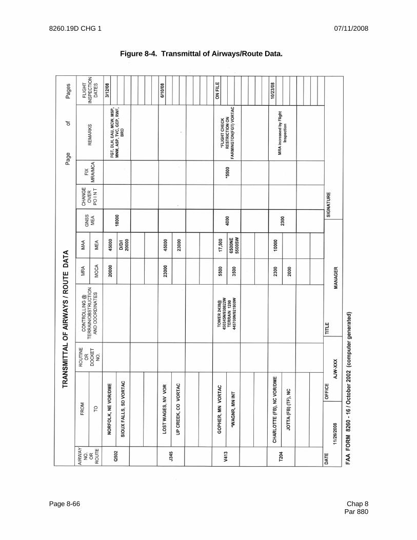
8260.19D CHG 1 07/11/2008
Page 8-66 Chap 8 Par 880
Figure 8-4. Transmittal of Airways/Route Data.

07/11/2008 8260.19D CHG 1 Appendix 1
Page 3
APPENDIX 1. ACRONYMS AND ABREVIATIONS
AAO adverse assumption obstacle AAUP Attention All Users Page AC Advisory Circular ADF automatic direction finder ADP automatic data processing AF Airway Facilities AFD Airport/Facility Directory AFS Flight Standards Service AFSS Automated Flight Service Station AGL above ground level AIP Aeronautical Information Publication ALS approach light system AOP NAS Operations Program AP Autopilot APO aviation policy and plans APV approach with vertical guidance ARA airborne radar approach ARC Airport Reference Code ARDH achieved reference datum height ARP airport reference point ARSR air route surveillance radar ARTCC Air Route Traffic Control Center ASAT airspace Simulation and Analysis for TERPS ASIP Airspace System Inspection Pilot AVNIS Aviation System Standards Information System ASOS automated surface observing system ASR airport surveillance radar ATC Air Traffic Control ATD along track distance ATRK along track AIM Aeronautical Information Manual AWOS Automated Weather Observing System AWOPM All Weather Operations/ Program Manager Baro VNAV barometric vertical navigation BC back course CA course-to-altitude leg (RNAV) CAT category CCW counter-clockwise CF course-to-fix leg (RNAV) CFR Code of Federal Regulations CG climb gradient CHDO Certificate Holding District Office
CIP capital investment plan CL course line CMO Certificate Management Office CNF computer navigation fix CONUS continental United States COP changeover point CRC cyclic redundancy cycle CRM collision risk model CW clockwise CY calendar year DA decision altitude DEM digital elevation model DER departure end of runway DF direction finder DF direct-to-fix leg (RNAV) DH decision height DG descent gradient DME distance measuring equipment DOC Department of Commerce DOD Department of Defense DOF digital obstruction file DOT Department of Transportation DP departure procedure DR dead reckoning DRP departure reference point DTED digital terrain elevation data EOVM emergency obstruction video map ESA emergency safe altitude ESV expanded service volume FAA Federal Aviation Administration FAC final approach course FAF final approach fix FAP final approach point FAS final approach segment FATO final approach takeoff area FB fly-by FCC Federal Communications Commission FD Flight Director FDC Flight Data Center FIFO Flight Inspection Field Office FIOO Flight Inspection Operations
Office FI/P Flight Information/Permanent FI/T Flight Information/Temporary FMO Frequency Management Office FMS frequency management system FO fly-over FPAP flight path alignment point

8260.19D CHG 1 07/11/2008 Appendix 1
Page 4
FPCP flight path control point FPFO Flight Procedures Field Office FSD Flight Standards Division FSDO Flight Standards District Office FSS Flight Service Station FTIP foreign terminal instrument procedure FTP fictitious threshold point FY fiscal year GCA ground controlled approach GNSS Global Navigation Satellite System GP glidepath GPA glidepath angle GPI ground point of intercept GPS Global Positioning System GS glide slope HAA height above airport HAE height above elipsoid HAL height above landing area elevation HAS height above surface HAT height above touchdown HATh height above threshold HF high frequency HMAS height of missed approach surface HUD head-up display IAC initial approach course IACC Interagency Air Cartographic Committee IAF initial approach fix IAP instrument approach procedure IAPA Instrument Approach Procedure Automation IFP instrument flight procedures IC intermediate course ICAO International Civil Aviation Organization IF intermediate fix IF initial fix (RNAV) IFP instrument flight procedure IFR instrument flight rules ILS instrument landing system IM inner marker ISA International Standard Atmosphere KIAS knots indicated airspeed LAAS local area augmentation system LDA localizer type directional aid LF low frequency LNAV lateral navigation
LOA letter of agreement LOB lines of business LOC localizer LOM Locator outer marker LP Localizer performance LPV Localizer performance with vertical guidance LTP landing threshold point MAA maximum authorized altitude MAH missed approach hold MALS minimum intensity approach lighting system MALSF minimum intensity approach lighting system with sequenced flashing MALSR minimum intensity approach lighting system with runway alignment indicator lights MAP missed approach point MCA minimum crossing altitude MDA minimum descent altitude MEA minimum en route altitude MHA minimum holding altitude MIA minimum IFR altitude MLS microwave landing system MM middle marker MOA memorandum of agreement MOA military operations area MOC minimum obstacle clearance MOCA minimum obstruction clearance altitude MRA minimum reception altitude MSA minimum safe/sector altitude MSL mean sea level MT mountainous terrain MTA minimum turn altitude MVA minimum vectoring altitude MVAC minimum vectoring altitude chart NACO National Aeronautical Charting
Office NAD North American Datum NAET National Aircraft Evaluation Team NAPT National Airspace and Procedures Team NAS National Airspace System NAVAID navigational aid NAVD North American Vertical Datum NCP NAS Change Proposal NDB non-directional radio beacon NFD National Flight Database NFDC National Flight Data Center

07/11/2008 8260.19D CHG 1 Appendix 1
Page 5
NFDD National Flight Data Digest NFPO National Flight Procedures Office NGA National Geospatial-Intelligence Agency NM nautical mile NOAA National Oceanic & Atmospheric Administration NOS National Ocean Service NOTAM Notices to Airmen Publication NPRM Notice of Proposed Rulemaking NTAP Notices to Airmen OC obstruction chart OCA obstacle clearance altitude OCS obstacle clearance surface ODP obstacle departure procedure OFA obstacle free area OIS obstacle identification surface OM outer marker PA precision approach PAPI precision approach path indicator PAR precision approach radar PCG positive course guidance PCL pilot controlled lighting PFAF precise final approach fix PinS point in space POI principal operations inspector PO proponent operator POC point of contact PRB Procedures Review Board PT procedure turn RA radio altimeter RAIL runway alignment indicator light RAPCON radar approach control RAPT Regional Airspace and Procedures Team RCL runway centerline RDOS runway departure obstacle screening RDP radar data processing RDP reference datum point RF constant-radius-to-a-fix leg (RNAV) RFO responsible Federal official RFSD Regional Flight Standards Division RNP required navigation performance RNAV area navigation ROC required obstacle clearance RSI remote status indicator RVR runway visual range
RWY runway SDF Simplified Directional Facility SDF stepdown fix SIAP standard instrument approach procedure SID standard instrument departure SM statute mile SMGCS Surface Movement Ground Control System SRTM shuttle radar terrain model SSALR short simplified approach lighting system with runway alignment indicator lights SSV standard service volume STAR standard terminal arrival SUA special use airspace TAA terminal arrival area TACAN tactical air navigational aid TCH threshold crossing height TDP touchdown point TDZ touchdown zone TDZE touchdown zone elevation TERPS U.S. Standard for Terminal Instrument Procedures TF track-to-fix leg (RNAV) THR threshold THRE threshold elevation TLS transponder landing system TPP terminal procedure publication TRACON terminal radar approach control facility TSO technical standard order UHF ultra high frequency USA U.S. Army USAF U.S. Air Force USCG U.S. Coast Guard USN U.S. Navy USNOF U.S. NOTAM Office VA heading-to-an-altitude leg (RNAV) VASI visual approach slope indicator VCA visual climb area VDA vertical descent area VDP visual descent point VFR visual flight rules VGSI visual glide slope indicator VHF very high frequency VI Vector-to-intercept leg (RNAV) VLF very low frequency VM vector-to-a-fix leg (RNAV) VMC visual meteorological conditions
8260.19D CHG 1 07/11/2008 Appendix 1
Page 6
VNAV vertical navigation VOR very high frequency omni- directional range VOR/DME VOR collocated with DME VORTAC VOR collocated with tactical air navigation VPA vertical path angle WAAS wide area augmentation system WCH wheel crossing height WP waypoint XTRK crosstrack

07/11/2008 8260.19D CHG 1 Appendix 2
Page 3
APPENDIX 2. FLIGHT PROCEDURES REFERENCES The following documents (latest versions) form the basic reference library for flight procedures activities. ORDERS AND NOTICES Number Subject 1000.1 Policy Statement of the Federal Aviation Administration 1050.1 Policies and Procedures for Considering Environmental Impacts 1350.5 Records Organization, Transfer, and Destruction Standards 1370.52 Information Resources Policy 1370.82 Information Systems Security Program 1720.23 Distribution of Aeronautical Charts and Related Flight Information Publications 1800.56 National Flight Standards Work Program Guidelines 5010.4 Airport Safety Data Program 5100.38 Airport Improvement Program (AIP) Handbook 6030.20 Electrical Power Policy 6050.32 Spectrum Management Regulations and Procedures Manual 6560.10 Runway Visual Range (RVR) 6700.20 Non-Federal Navigational Aids and Air Traffic Control Facilities 6750.16 Siting Criteria for Instrument Landing Systems 6750.24 Instrument Landing System and Ancillary Electronic Component Configuration and Performance Requirement 6750.49 Maintenance of Instrument Landing Systems (ILS) Facilities 6850.2 Visual Guidance Lighting Systems 6850.5 Maintenance of Lighted Navigational Aids. 6950.2 Electrical Power Policy Implementation at National Airspace System Facilities 7031.2 Airway Planning Standards #1 Terminal Air Navigation Facilities and Air Traffic Services 7031.3 Airway Planning Standards #2 Air Route Traffic Control 7032.5 Airport Surface Detection Equipment (ASDE-3) Air Traffic Service Operational Requirements 7100.9 Standard Terminal Arrival 7110.10 Flight Services 7110.19 Designation Taxiways as Temporary Runways 7110.22 Arrival and Departure Handling of High Performance Aircraft 7110.65 Air Traffic Control 7110.79 Charted Visual Flight Procedures 7130.3 Holding Pattern Criteria
AT 7130.8 Development of Holding Pattern Criteria and Procedures 7210.3 Facility Operations and Administration 7210.37 En Route Minimum IFR Altitude (MIA) Sector Charts 7232.5 Reduced or Increased Operating Hours for ATCT’s/Approach Control Facilities 7340.1 Contractions 7350.2 Air Traffic Operational Coding System 7350.7 Location Identifiers 7400.2 Procedures for Handling Airspace Matters 7450.1 Special Use Airspace Management System 7610.4 Special Operations 7900.2 Reporting of Electronic Navigation Aids and Communication Facilities Data to the NFDC 7900.5 Surface Weather Observing
8260.19D CHG 1 07/11/2008 Appendix 2
Page 4
ORDERS AND NOTICES (Continued) 7930.2 Notices to Airmen (NOTAMs) 8200.1 United States Standard Flight Inspection Manual 8240.47 Determination of Instrument Landing System (ILS) Glidepath Angle, Reference Datum
Heights (RDH) 8260.3 United States Standard for Terminal Instrument Procedures (TERPS)
VN 8260.4 ILS Obstacle Risk Analysis 8260.15 United States Army Terminal Instrument Procedures Service 8260.16 Airport Obstruction Surveys 8260.19 Flight Procedures and Airspace 8260.23 Calculation of Radio Altimeter Height 8260.26 Establishing and Scheduling Standard Instrument Procedure Effective Dates 8260.31 Foreign Terminal Instrument Procedures 8260.32 United States Air Force Terminal Instrument Procedures Service 8260.37 Heliport Civil Utilization of Collocated Microwave Landing System (MLS) 8260.40 Flight Management System (FMS) Instrument Procedures Development 8260.42 Helicopter Global Positioning System (GPS) Nonprecision Approach Criteria 8260.43 Flight Procedures Management Program 8260.44 Civil Utilization of Area Navigation (RNAV) Departure Procedures 8260.45 Terminal Arrival Area (TAA) Design Criteria 8260.46 Departure Procedure (DP) Program 8260.54 The United States Standard for Area Navigation (RNAV) 8400.8 Procedures for Approval of Facilities for FAR Part 121 and Part 135 CAT III Operations 8400.10 Air Transportation Operations Inspector’s Handbook 8400.13 Procedures for the Approval of Special Authorization Category II and Lowest Standard Category I Operations 8700.1 General Aviation Operations Inspector's Handbook ADVISORY CIRCULARS FAA-H-8083-15 Instrument Flying Handbook FAA-H-8261-1A Instrument Procedures Handbook 70/7460-1 Obstruction Marking and Lighting 70/7460-2 Proposed Construction or Alteration of Objects that May Affect the Navigable Airspace 73-2 IFR Helicopter Operations in the Northeast Corridor 90-42 Traffic Advisory Practices at Airports Without Operating Control Towers 90-45 Approval of Area Navigation Systems for Use in the U.S. National Airspace System 90-80 Approval for Offshore Standard Approach Procedures (OSAP), Airborne Radar Approaches
(ARA), and Helicopter En Route Descent Areas (HEDA) 91-14 Altimeter Setting Sources 91-16 Category II Operations-General Aviation Airplanes 91-54 Automatic Reporting Systems-Altimeter Setting and Other Operational Data 97-1 Runway Visual Range (RVR) 120-28 Criteria for Approval of Category III Weather Minima for Takeoff, Landing, and Rollout 120-29 Criteria for Approving Category I and Category II Landing Minima for FAR 121 Operators 120-91 Airport Obstacle Analysis 150/5070-6 Airport Master Plans 150/5200-28 Notices to Airmen (NOTAMs) for Airport Operators 150/5300-13 Airport Design

07/11/2008 8260.19D CHG 1 Appendix 3
Page 5
(i) World Aeronautical Chart (WAC), Sectional Chart, and VFR Terminal Chart. 1 Terrain features which are not marked as spot elevations: Chart Horizontal Vertical* WAC +1,700 ft (500 m) +500 ft (150 m) Sec +900 ft (275 m) +250 ft (75 m) VFR +500 ft (150 m) +250 ft (75 m) *1/2 contour line 2 When mountain peaks are specifically marked by a spot elevation, the vertical accuracy changes to 20 ft (6 m). Horizontal accuracy determined by chart type as specified in paragraph 101b. 3 When these charts are used to establish coordinates, it must be recognized that the Inter-Agency Air Cartographic Committee (IACC) charting standards permit displacement of objects to provide for relative depiction. To account for these additional errors, the horizontal accuracy factors must be doubled for manmade obstacles depicted on WAC, Sectional, and VFR charts. (3) Department of Defense. (a) National Geospecial-intelli-gence Agency (NGA): 1 Digital Terrain Elevation Data (DTED) (Level 0) 1 kilometer postings from 1:350,000 charts, +500 ft (150 m) hori-zontally and +100 ft (30 m) vertically Code 5E. DTED (Level 1), 100 meter postings +50 m (164 ft) horizontally and +30 m (98 ft) vertically. Code 4E. DTED (Level 2), 30 meter postings +23 m (76 ft) horizontally and +18 m (59 ft) vertically. Code 3E. 2 Shuttle Radar Terrain Model (SRTM): Level 1 (Foreign) 90 meter posting, equivalent to 1:250,000. Level 2 (CONUS) 30 meter posting, equivalent to 1:50,000. Level 1 and 2 accuracies are 20 meter horizontal and 16 meter vertical. Code 3D.
3 Vertical Obstruction Feature Database (VOFD). Populated using multiple sources. Obstruction attributes contain associated source accuracy code (Surveyed to Reported). Code 1A to 9I. 4 Joint Operations Graphic (JOG) - AIR, 2nd Series, (1:250,000 scale), +500 ft (150 m) horizontally and +125 ft (38 m) vertically. Code 5E. 5 Topographical Line Maps (TLM), (1:50,000 and 1:100,000 scale), +50 ft (15 m) horizontally and +20 ft (6 m) vertically. Code 2C. (b) OC surveys conducted by U.S. Army Topographic Units must have the same accuracy standards as those developed by the Department of Commerce [see paragraph 101b(1)(a)]. (4) Department of Interior. U.S. Geological Survey data in magnetic tape files are claimed to be accurate to +1,000 ft (300 m) horizontally and +100 ft (30 m) vertically. Code 6E. For the following charts, when obstacles or mountain peaks are specifically marked by a spot elevation, the vertical accuracy changes to +3 ft (1 m). Otherwise, these charts have the following accuracies: (a) Topographical charts (1:250,000 scale), +1,000 ft (300 m) horizontally and +125 ft (38 m) vertically. Code 6E. (b) Topographical charts (1:100,000 scale), +250 ft (75 m) horizontally and +125 ft (38 m) vertically. Code 4E. (c) Topographical charts (1:62,500 or 1:63,360 scale), +250 ft (75 m) horizontally and +50 ft (15 m) vertically. Code 4D. (d) Topographical charts [1:20,000, 1:24,000) (7 1/2 min. Quad series), and 1:25,000], +40 ft (12 m) horizontally and +20 ft (6 m) vertically. Code 2C. 1 When these charts are used to establish coordinates, it must be recognized that the Inter-Agency Air Cartographic

8260.19D CHG 1 07/11/2008 Appendix 3
Page 6
Committee (IACC) charting standards permit displacement of objects to provide for relative depiction. To account for these additional errors (as well as human scaling errors), the following accuracy factors will be used: Landmarks Owner Depicted Marked on Chart Positions 1:250,000 7G 8H 1:62,500 or 1:63,360 (</ = 40 ft contours) 4E 5E (80 ft contours) 4F 5F 1:20,000 or 1:24,000 (</ = 10 ft contours) 4D 5D (20 ft contours) 4D 5E 1:100,000 5F 6G
(5) Digital Elevation Data. U.S. Geological Survey data for terrain elevations is typically based on Digital Elevation Models (DEM). Source documentation from the NOS supports the following horizontal and vertical accuracies; these values must be used in instrument procedure construction: (a) DEM 7.5 Minute (Level 1), +13 m (43 ft) horizontally and +14 m (46 ft) vertically. Code 2D. (b) DEM 7.5 Minute (Level 2), +13 m (43 ft) horizontally and +17 m (56 ft) vertically. Code 2E. (c) DEM 1 Degree (1:250,000 scale), +130 m (427 ft) horizontally and +30 m (98 ft) vertically. Code 5E.

07/11/2008 8260.19D CHG 1 Appendix 12
Page 3
APPENDIX 12. FINAL APPROACH SEGMENT (FAS) DATA BLOCK CYCLIC REDUNDANCY CHECK (CRC) REQUIREMENTS
Content of the FAS Data Block. Each FAS data block contains 22 elements (fields) (20 elements for LAAS) that include the CRC remainder. The specific order and coding of the fields must be followed rigorously to ensure avionics compatibility. Until the process for electronic transmittal of this data is developed by the NFPO, the following FAS Data Block information must be documented on FAA Form 8260-10, Continuation Sheet, especially prepared for that purpose (see figures A12-1 and 2). This form will comprise the protected data pending development of an internal CRC process, and will be forwarded to the charting agencies for further processing and CRC protection. For helicopter Point-in-Space (PinS) operations, see RTCA Document DO-229D, Appendix Q, for unique FAS Data Block requirements. 1. Fields needed for the Final Approach Segment (FAS) Data Block record for approaches using WAAS (LPV minima) and are included in the CRC wrap: Data Field Field Size Data Type Operation Type 2 characters Unsigned Integer SBAS Service Provider Identifier 2 characters Unsigned Integer Airport Identifier 4 characters Alphanumeric Runway 2 characters Numeric Runway Letter 2 characters Numeric Approach Performance Designator 1 character Unsigned Integer Route Indicator 1 character Alpha Reference Path Data Selector 2 characters Unsigned Integer Reference Path Identifier (Approach ID) 4 characters Alphanumeric LTP/FTP Latitude 11 characters Alphanumeric LTP/FTP Longitude 12 characters Alphanumeric LTP/FTP Ellipsoidal Height 6 characters Signed Integer FPAP Latitude 11 characters Alphanumeric FPAP Longitude 12 characters Alphanumeric Threshold Crossing Height (TCH) 7 characters Alphanumeric TCH Units Selector (meters or feet used) 1 character Feet or Meters Glidepath Angle (GPA) 4 characters Unsigned Integer Course Width at Threshold 5 characters Unsigned Integer Length Offset 4 characters Unsigned Integer Horizontal Alert Limit (HAL) (LPV Procedures) 3 characters Numeric Vertical Alert Limit (VAL) (LPV Procedures) 3 characters Numeric 2. Fields needed for integrity monitoring, and calculated using binary representation of FAS Data Block (as described in RTCA/DO-229C, Minimum Operational Performance Standards for Global Positioning System/Wide Area Augmentation System Airborne Equipment and as amended by TSO-C146A). Data Field Field Size Data Type Precision Approach Path Point Data CRC Remainder 8 characters Hexadecimal 3. Fields not included in the FAS Data Block, but needed for the Precision Approach Path Point record, and which are not CRC wrapped.

8260.19D CHG 1 07/11/2008 Appendix 12
Page 4
Data Field Field Size Data Type ICAO Code 2 characters Alphanumeric LTP Orthometric Height 6 characters Signed Integer FPAP Orthometric Height 6 characters Signed Integer Horizontal Alert Limit (HAL) (LAAS procedures) 3 characters Numeric Vertical Alert Limit (VAL) (LAAS procedures) 3 characters Numeric 4. Explanation of data field entries (in the general order they appear in the FAS Data Block): a. Operation Type. A number from 0 to 15 that indicates the type of the final approach segment. Example: 0 is coded for a straight-in and offset approach procedure. b. SBAS Service Provider Identifier. A number from 0 to 15 that associates the approach procedure to a particular satellite based approach system service provider. For GBAS applications, this data is ignored. Example: 0 (WAAS) c. Airport Identifier. The four-character ICAO location identifier assigned to an airport. Where there is a national airport identifier but no ICAO location identifier, the three- or four-character national identifier is used. Where only three characters are provided, the trailing space is to be left blank. Example: KDEN, YSSY, NZWN, FAEL, 3SL_, OH23 d. Runway. Runways are identified by one or two numbers with a valid range of 1-36. Use of “0” in the runway number is obsolete. Examples: 26, 8, 18, 2
e. Runway Letter. A runway letter (left (L), right (R), or center (C)) is used to differentiate between parallel runways. The valid range is 00 through 11. The convention for coding is as follows:
00 = no letter 10 = C (center)
01 = R (right) 11 = L (left) f. Approach Performance Designator. A number from 0 to 7 that identifies the type of approach. An “0” is used to identify an LPV approach procedure and a “1” indicates a Category I approach procedure. Leave blank (null) for LAAS procedures. Other values are reserved for future use.

07/11/2008 8260.19D CHG 1 Appendix 12
Page 5
Example: 0 = LPV and LP g. Route Indicator. A single alpha character (A through Z or blank, omitting I and O) used to differentiate between multiple final approach segments to the same runway or heliport. The first approach to a runway is labeled “Z.” Additional alpha characters are incrementally assigned. Example: Z, Y, X, etc. h. Reference Path Data Selector (RPDS). A number (0-48) that enables automatic tuning of a procedure by LAAS avionics. The number is related to the frequency of the VHF data broadcast and a 5-digit tuning identifier. The future ICAO SBAS SARPS will provide further information. Always "0" for WAAS operations. Example: 0 i. Reference Path Identifier. A four-character identifier that is used to confirm selection of the correct approach procedure. This identifier is defined with a “W” signifying WAAS followed by the runway number. For ground based augmentation systems (e.g., LAAS) the identifier is defined with a “G” followed by the runway number. The last character, beginning with the letter “A”, excluding the letters “C,” “L,” and “R,” will be used to define the first procedure, followed by a succeeding letter for each procedure to a particular runway. For example, an airport has three parallel runways and the left and right runways have both a straight-in procedure and an offset procedure; the center runway has a straight-in procedure only. The following (extreme) examples would be applicable: Example: W09A & W09B would define the two unique FAS data blocks to RWY 09L. W09D would be used to define the FAS data block for RWY 09C. W09E & W09F would be used to define the FAS data blocks for RWY 09R. G09A & G09B would define the two unique FAS data blocks to RWY 09L. G09D would be used to define the FAS data block for RWY 09C. G09E & G09F would be used to define the FAS data blocks for RWY 09R. Note: These suffixes do not have to be in any particular order so as to allow procedures to be added at a later time without changing existing FAS data blocks. j. Landing Threshold Point (LTP)/Fictitious Threshold Point (FTP) - Latitude. Represents the latitude of the threshold defined in WGS-84 coordinates and entered to five ten-thousandths of an arc second (The last digit must be rounded to either an 0 or 5). Use the FTP Latitude for offset procedures. The most significant bit is the sign bit: 0 = Positive (Northern Hemisphere); 1 = Negative (Southern Hemisphere). However, for documentation purposes, identify the Latitude as follows: Example: 225436.2125N (11 characters) for 22°54'36.2125" N k. Landing Threshold Point (LTP)/Fictitious Threshold Point (FTP) - Longitude. Represents the longitude of the threshold defined in WGS-84 coordinates and entered to

8260.19D CHG 1 07/11/2008 Appendix 12
Page 6
five ten-thousandths of an arc second (The last digit must rounded to either an 0 or 5). Use the FTP Longitude for offset procedures. The most significant bit is the sign bit: 0 = Positive (Eastern Hemisphere); 1 = Negative (Western Hemisphere). However, for documentation purposes, identify the Latitude as follows: Example: 1093247.8780E (12 characters) for 109°32'47.8780" E l. LTP/FTP Height Above Ellipsoid (HAE). The height expressed in meters reference the WGS-84 ellipsoid (see Order 8260.54, paragraph 1.7.14). The first character is a + or – and the resolution value is in tenths of a meter with the decimal point suppressed. Use the LTP HAE for offset procedures. Example: +00356 (+35.6m), -00051(-5.1m), +01566 (+156.6m), -00022 (-2.2m) m. Flight Path Alignment Point (FPAP) - Latitude. A point located on a geodesic line or an extension of a geodesic line calculated between the LTP and the designated center of the opposite runway-landing threshold. It is positioned at a distance from the LTP to support a prescribed procedure design angular splay and course width, as well as functionality associated with an aircraft. It is used in conjunction with the LTP to determine the lateral alignment of the vertical plane containing the path of the RNAV final approach segment. On shorter runways, the FPAP may be located off the departure end of the landing runway. The latitude of the runway FPAP is defined in WGS-84 coordinates and entered to five ten-thousandths of an arc second (The last digit must be rounded to either an 0 or 5). The most significant bit is the sign bit: 0 = Positive (Northern Hemisphere); 1 = Negative (Southern Hemisphere). However, for documentation purposes, identify the Latitude as follows: Example: 225436.2125N (11 characters) for 22°54'36.2125" N n. FPAP - Longitude. The longitude of the runway FPAP is defined in WGS-84 coordinates and entered to five ten-thousandths of an arc second (The last digit must be rounded to either an 0 or 5). The most significant bit is the sign bit 0 = Positive (Eastern Hemisphere); 1 = Negative (Western Hemisphere). However, for documentation purposes, identify the Latitude as follows: Example: 1093247.8780E (12 characters) for 109°32'47.8780" E o. Threshold Crossing Height (TCH). The designated crossing height of the flight path angle above the LTP (or FTP). The allowable range of values is defined in TERPS table 18A. Example: 00055.0 (55.0 feet); 00042.0 (42.0 feet) p. TCH Units Selector. This character defines the units used to describe the TCH.

07/11/2008 8260.19D CHG 1 Appendix 12
Page 7
Example: F = feet M = meters q. Glidepath Angle. The angle of the approach path (glidepath) with respect to the horizontal plane defined according to WGS-84 at the LTP/FTP. It is specified in degrees. Example: 02.75 (2.75°), 06.20 (6.20°), 03.00 (3.00°) r. Course Width at Threshold. The semi-width (in meters) of the lateral course at the LTP/FTP, defining the lateral offset at which the receiver will achieve full-scale deflection. In combination with the distance to the FPAP, the course width defines the sensitivity of the lateral deviations throughout the approach. The allowable range varies from 80m to 143.75m. See Order 8260.54, paragraph 2.11, to determine course width. When the LPV procedure is designed to overlie an ILS/MLS procedure, use the course width at threshold value from the flight inspection report of the underlying (ILS/MLS) system. If the Localizer course width at threshold is less than 80m, use 80m as the default value. For offset procedures, use the course width at the FTP. Example: 106.75 s. Δ Length Offset. The distance from the stop end of the runway to the FPAP. It defines the location where lateral sensitivity changes to the missed approach sensitivity. The value is in meters with the limits being 0 to 2,032 m. This distance is rounded to the nearest 8-meter value. If the FPAP is located at the designated center of the opposite runway end, the distance is zero. For offset procedures, the length of offset is coded as zero. Example: 0000, 0424 t. Precision Approach Path Point CRC Remainder. An 8-character hexadecimal representation of the calculated remainder bits used to determine the integrity of the FAS Data Block data during transmission and storage. This information will be computed electronically with use of the electronic transmittal software and documented on Form 8260-10 (see figures A11-1 and A11-2). Example: CRC Remainder: E104FC14 u. ICAO Code. The first two designators of the ICAO location identifier, as identified in ICAO Doc 7910. In the Continental United States, the country code will begin with the letter “K” followed by a numeric character obtained from figure A11-3. Alaska, Hawaii, and U.S. Possessions will be as described in the ICAO Doc 7910. Example: K1, K7, PH, PA, MM, ER

8260.19D CHG 1 07/11/2008 Appendix 12
Page 8
v. Orthometric Height. The height of the LTP or FPAP, as related to the geoid, and presented as an MSL elevation defined to a tenth of a meter resolution with the decimal point suppressed. For the purpose of documenting this in the “Additional Path Point Record Information,” the LTP and FPAP orthometric height will be the same and based on the LTP elevation. The value is preceded by a “+” or “-”. Example: +00362 (+36.2m), +02478 (+247.8m), -00214 (-21.4m) w. Horizontal Alert Limit (HAL). The HAL is the radius of a circle in the horizontal plane (the local plane tangent to the WGS-84 ellipsoid), with its center being at the true position, that describes the region which is required to contain the indicated horizontal position with the required probability for a particular navigation mode assuming the probability of a GPS satellite integrity failure being included in the position solution is less than or equal to 10-4 per hour. The range of values is 0 to 50.8m with a 0.2 resolution. The HAL for LPV procedures developed using Order 8260.50 is a fixed value at 40.0 meters. Note: A HAL is not part of the FAS data block/CRC wrap for LAAS procedures. Example: HAL 40.0
x. Vertical Alert Limit (VAL). The VAL is half the length of a segment on the vertical axis (perpendicular to the horizontal plane of the WGS-84 ellipsoid), with its center being at the true position, that describes the region which is required to contain the indicated vertical position with a probability of 1-10-7 per approach, assuming the probability of a GPS satellite integrity failure being included in the position solution is less than or equal to 10-4 per hour. The range of values is 0 to 50.8m with a 0.2 resolution. The VAL for LPV procedures is a fixed value at 50.0 meters where the HATh/HAT is 250 feet or greater. If an LPV procedure has been established to support a HATh/HAT less than 250 feet (no less than 200 feet), a VAL of 35 meters will be used.
Note 1: A VAL of 00.0 indicates that the vertical deviations should not be used (i.e., a lateral-only {LP} approach).
Note 2: A VAL is not part of the FAS data block/CRC wrap for LAAS procedures.
Example: VAL 50.0 VAL 35.0