chap er 6chapter 6c p 6ha er - wbuthelp.com er 6chapter 6c p 6ha er ... to convert it into useful...
TRANSCRIPT

Chap er 6Chapter 6C p 6ha er Chapter 6
m t t m Steam TSteam T b neb neurbineurbine
Steam turbine is one of the most important prime mover for generating electricity. This fallsunder the category of power producing turbo-machines. In the turbine, the energy level of the workingfluid goes on decreasing along the flow stream. Single unit of steam turbine can develop power rangingfrom 1 mW to 1000 mW. In general, 1 mW, 2.5 mW, 5 mW, 10 mW, 30 mW, 120 mW, 210 mW, 250 mW,350 mW, 500 mW, 660 mW, 1000 mW are in common use. The thermal efficiency of modern steampower plant above 120 mW is as high as 38% to 40%.
The purpose of turbine technology is to extract the maximum quantity of energy from the work-ing fluid, to convert it into useful work with maximum efficiency, by means of a plant having maximumreliability, minimum cost, minimum supervision and minimum starting time. This chapter deals with thetypes and working of various types of steam turbine. The construction details are given in chapter 15.
6.1. PRINCIPLE OF OPERATION OF STEAM TURBINE
The principle of operation of steam turbine is entirely different from the steam engine. In recip-rocating steam engine, the pressure energy of steam is used to overcome external resistance and thedynamic action of steam is negligibly small. But the steam turbine depends completely upon the dy-namic action of the steam. According to Newton’s Second Law of Motion, the force is proportional tothe rate of change of momentum (mass × velocity). If the rate of change of momentum is caused in thesteam by allowing a high velocity jet of steam to pass over curved blade, the steam will impart a force tothe blade. If the blade is free, it will move off (rotate) in the direction of force. In other words, the motivepower in a steam turbine is obtained by the rate of change in moment of momentum of a high velocity jetof steam impinging on a curved blade which is free to rotate. The steam from the boiler is expanded ina passage or nozzle where due to fall in pressure of steam, thermal energy of steam is converted intokinetic energy of steam, resulting in the emission of a high velocity jet of steam which, Principle ofworking impinges on the moving vanes or blades of turbine (Fig. 6.1).
C1
C2
Force
Blade
Fig. 6.1. Turbine Blade.
Attached on a rotor which is mounted on a shaft supported on bearings, and here steam under-goes a change in direction of motion due to curvature of blades which gives rise to a change in momen-
mywbut.com
1

tum and therefore a force. This constitutes the driving force of the turbine. This arrangement is shown.It should be realized that the blade obtains no motive force from the static pressure of the steam or fromany impact of the jet, because the blade in designed such that the steam jet will glide on and off the bladewithout any tendency to strike it.
As shown in Fig. 6.2, when the blade is locked the jet enters and leaves with equal velocity, andthus develops maximum force if we neglect friction in the blades. Since the blade velocity is zero, nomechanical work is done. As the blade is allowed to speed up, the leaving velocity of jet from the bladereduces, which reduces the force. Due to blade velocity the work will be done and maximum work isdone when the blade speed is just half of the steam speed. In this case, the steam velocity from the bladeis near about zero i.e. it is trail of inert steam since all the kinetic energy of steam is converted into work.The force and work done become zero when the blade speed is equal to the steam speed. From the abovediscussion, it follows that a steam turbine should have a row of nozzles, a row of moving blades fixed tothe rotor, and the casing (cylinder). A row of nozzles and a raw of moving blades constitutes a stage ofturbine.
Nozzle
Entering velocity= C1
Blade velocityu = 0
F
Bladelocked
Leavingvelocity = C2
( )b1
C1
C2
( )b2
u = C /41
u = C /21C1
C = 02
( )b3
F
Fig. 6.2. Action of Jet on Blade.
6.2. CLASSIFICATION OF STEAM TURBINE
Steam turbine may be classified as follows: -
(A) On the Basis of Principle of Operation :
(i) Impulse turbine
(a) Simple, (b) Velocity stage, (c) Pressure stage, (d) combination of (b) and (c).
mywbut.com
2

(ii) Impulse-reaction turbine
(a) 50% (Parson’s) reaction, (b) Combination of impulse and reaction.
(i) Impulse Turbine: If the flow of steam through the nozzles and moving blades of a turbinetakes place in such a manner that the steam is expanded only in nozzles and pressure at the outlet sidesof the blades is equal to that at inlet side; such a turbine is termed as impulse turbine because it works onthe principle of impulse. In other words, in impulse turbine, the drop in pressure of steam takes placeonly in nozzles and not in moving blades. This is obtained by making the blade passage of constantcross- section area
As a general statement it may be stated that energy transformation takes place only in nozzles andmoving blades (rotor) only cause energy transfer. Since the rotor blade passages do not cause any accel-eration of fluid, hence chances of flow separation are greater which results in lower stage efficiency.
(ii) Impulse-Reaction Turbine: In this turbine, the drop in pressure of steam takes place in fixed(nozzles) as well as moving blades. The pressure drop suffered by steam while passing through themoving blades causes a further generation of kinetic energy within the moving blades, giving rise toreaction and adds to the propelling force which is applied through the rotor to the turbine shaft. Sincethis turbine works on the principle of impulse and reaction both, so it is called impulse-reaction turbine.This is achieved by making the blade passage of varying cross-sectional area (converging type).
In general, it may be stated that energy transformation occurs in both fixed and moving blades.The rotor blades cause both energy transfer and transformation. Since there is an acceleration of flowin moving blade passage hence chances of separation of flow is less which results in higher stageefficiency.
(B) On the basis of “Direction of Flow’’ :
(i) Axial flow turbine, (ii) Radial flow turbine, (iii) Tangential flow turbine.
(i) Axial Flow Turbine. In axial flow turbine, the steam flows along the axis of the shaft. It is themost suitable turbine for large turbo-generators and that is why it is used in all modem steam powerplants.
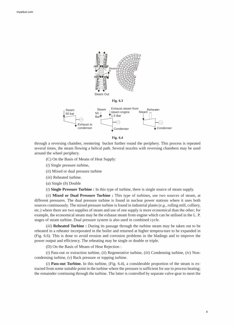
(ii) Radial Flow Turbine. In this turbine, the steam flows in the radial direction. It incorporatestwo shafts end to end, each driving a separate generator. A disc is fixed to each shaft. Rings of 50%reaction radial-flow bladings are fixed to each disk. The two sets of bladings rotate counter to eachother. In this way, a relative speed of twice the running speed is achieved and every blade row is made towork. The final stages may be of axial flow design in order to achieve a larger area of flow. Since thistype of turbine can be warmed and started quickly, so it is very suitable for use at times of peak load.Though this type of turbine is very successful in the smaller sizes but formidable design difficulties havehindered the development of large turbines of this type. In Sweden, however, composite radial/axialflow turbines have been built of outputs upto 275 MW. Sometimes, this type of turbine is also known asLiungstrom turbine after the name of its inventor B and F. Liungstrom of Sweden (Fig. 6.3).
(iii) Tangential Flow Turbine. In this type, the steam flows in the tangential direction. Thisturbine is very robust but not particularly efficient machine, sometimes used for driving power stationauxiliaries. In this turbine, nozzle directs steam tangentially into buckets milled in the periphery of asingle wheel, and on exit the steam turns
mywbut.com
3
Steamin
Steam Out
Fig. 6.3
Steam50 bar
Exhaust tocondenser
Steam50Bar
Exhaust steam fromsteam engine1.5 Bar
Condenser
SteamReheater
Condenser
Fig. 6.4
through a reversing chamber, reentering bucket further round the periphery. This process is repeatedseveral times, the steam flowing a helical path. Several nozzles with reversing chambers may be usedaround the wheel periphery.
(C) On the Basis of Means of Heat Supply:
(i) Single pressure turbine,
(ii) Mixed or dual pressure turbine
(iii) Reheated turbine.
(a) Single (b) Double
(i) Single Pressure Turbine : In this type of turbine, there is single source of steam supply.
(ii) Mixed or Dual Pressure Turbine : This type of turbines, use two sources of steam, atdifferent pressures. The dual pressure turbine is found in nuclear power stations where it uses bothsources continuously. The mixed pressure turbine is found in industrial plants (e.g., rolling mill, colliery,etc.) where there are two supplies of steam and use of one supply is more economical than the other; forexample, the economical steam may be the exhaust steam from engine which can be utilised in the L. P.stages of steam turbine. Dual pressure system is also used in combined cycle.
(iii) Reheated Turbine : During its passage through the turbine steam may be taken out to bereheated in a reheater incorporated in the boiler and returned at higher tempera-ture to be expanded in(Fig. 6.6). This is done to avoid erosion and corrosion problems in the bladings and to improve thepower output and efficiency. The reheating may be single or double or triple.
(D) On the Basis of Means of Heat Rejection :
(i) Pass-out or extraction turbine, (ii) Regenerative turbine, (iii) Condensing turbine, (iv) Non-condensing turbine, (v) Back pressure or topping turbine.
(i) Pass-out Turbine. In this turbine, (Fig. 6.4), a considerable proportion of the steam is ex-tracted from some suitable point in the turbine where the pressure is sufficient for use in process heating;the remainder continuing through the turbine. The latter is controlled by separate valve-gear to meet the
mywbut.com
4

difference between the pass-out steam and electrical load requirements. This type of turbine is suitablewhere there is dual demand of steam-one for power and the other for industrial heating, for examplesugar industries. Double pass-out turbines are sometimes used.
(ii) Regenerative Turbine. This turbine incorporates a number of extraction branches, throughwhich small proportions of the steam are continuously extracted for the purpose of heating the boilerfeed water in a feed heater in order to increase the thermal efficiency of the plant. Now a days, all steampower plants are equipped with reheating and regenerative arrangement.
(iii) Condensing Turbine. In this turbine, the exhaust steam is condensed in a condenser and thecondensate is used as feed water in the boiler. By this way the condensing turbine allows the steam toexpand to the lowest possible pressure before being condensed. All steam power plants use this type ofturbine.
(iv) Non-Condensing Turbine. When the exhaust steam coming out from the turbine is notcondensed but exhausted in the atmosphere is called non-condensing turbine. The exhaust steam is notrecovered for feed water in the boiler.
(v) Back Pressure or Topping Turbine. This type of turbine rejects the steam after expansion tothe lowest suitable possible pressure at which it is used for heating purpose. Thus back pressure turbinesupplies power as well as heat energy.
The back pressure turbine generally used in sugar industries provides low pressure steam forheating apparatus, where as a topping turbine exhausts into a turbine designed for lower steam condi-tions.
(E) On the Basis of Number of Cylinder: Turbine may be classified as
(i) Single cylinder and (ii) Multi-cylinder.
(i) Single Cylinder. When all stages of turbine are housed in one casing, then it is called singlecylinder. Such a single cylinder turbine uses one shaft.
(ii) Multi-Cylinder. In large output turbine, the number of the stages needed becomes so highthat additional bearings are required to support the shaft. Under this circumstances, multi-cylinders areused.
(F) On the Basis of Arrangement of Cylinder Based on General Flow of Steam. (i) Single flow,(ii) Double flow, and (iii) Reversed flow
Single Flow. In a single flow turbines, the steam enters at one end, flows once [Fig. 6.5(a)] through
Single flow
( )a ( )b ( )c
Double flow Reversed flow
Fig. 6.5
the bladings in a direction approximately parallel to this axis, emerges at the other end. High pressurecylinder uses single flow. This is also common in small turbines.
Double Flow. In this type of turbines, the steam enters at the centre and divides, the two portionspassing axially away from other through separate sets of blading on the same rotor Fig. 6.5(b). The low
mywbut.com
5

pressure cylinder normally uses double flow). This type of unit is completely balanced against the endthrust and gives large area of flow through two sets of bladings. This also helps in reducing the bladeheight as mass flow rate becomes half as compared to single flow for the same conditions.
Reversed Flow. Reversed flow arrangement is sometimes used in h.p, cylinder where highertemperature steam is used on the larger sets in order to minimise differential expansion i.e. unequalexpansion of rotor and casing. The use of single, double and reversed flow is shown in the layoutFig. 6.5(c).
(G) On the Basis of Number of Shaft
(i) Tandem compound, (ii) Cross compound
(i) Tandem Compound. Most multi-cylinder turbines drive a single shaft and single generatorSuch turbines are termed as tandem compound turbines.
(ii) Cross Compound. In this type, two shafts are used driving separate generator. The may beone of turbine house arrangement, limited generator size, or a desire to run shafting at half speed. Thelatter choice is sometimes preferred so that for the same centrifugal stress, longer blades may be used,giving a larger leaving area, a smaller velocity and hence a small leaving loss.
(H) On the Basis of Rotational Speed (i) constant speed turbines(ii) Variable speed turbines
(i) Constant Speed Turbines. Requirements of rotational speed are extremely rigid in turbineswhich are directly connected to electric generators as these must be a-c unit except in the smallest sizesand must therefore run at speeds corresponding to the standard number of cycles per second and gov-erned by the following equation :
N = 120 × Number of cycles per second = 120 f/pNumber of poles
The minimum number of poles, in a generator is two and correspondingly the maximum possiblespeed for 60 cycle is 3,600 rpm; for 50 c/s of frequency, the speeds would be 3,000, 1500 and 750 rpmfor 2, 4 and 8 poles machines respectively.
(ii) Variable Speed Turbines. These turbines have geared units and may have practically anyspeed ratio between the turbine and the driven machine so that the turbine may be designed for its ownmost efficient speed. Such turbines are used to drive ships, compressors, blowers and variable frequencygenerators.
6.3. THE SIMPLE IMPULSE TURBINE
This type of turbine works on the principle of impulse and is shown diagrammatically. It mainlyconsists of a nozzle or a set of nozzles, a rotor mounted on a shaft, one set of moving blades attached tothe rotor and a casing. The uppermost portion of the diagram shows a longitudinal section through theupper half of the turbine, the middle portion shows the development of the nozzles and blading i.e. theactual shape of the nozzle and blading, and the bottom portion shows the variation of absolute velocityand absolute pressure during flow of steam through passage of nozzles and blades. The example of thistype of turbine is the de-Laval Turbine.
It is obvious from the figure that the complete expansion of steam from the steam chest pressureto the exhaust pressure or condenser pressure takes place only in one set of nozzles i.e. the pressure droptakes place only in nozzles. It is assumed that the pressure in the recess between nozzles and blades
mywbut.com
6

remains the same. The steam at condenser pressure or exhaust pressure enters the blade and comes outat the same pressure i.e. the pressure of steam in the blade passages remains approximately constant andequal to the condenser pressure. Generally, converging-diverging nozzles are used. Due to the relativelylarge ratio of expansion of steam in the nozzles, the steam leaves the nozzles at a very high velocity(supersonic), of about 1100 m/s. It is assumed that the velocity remains constant in the recess betweenthe nozzles and the blades. The steam at such a high velocity enters the blades and reduces along thepassage of blades and comes out with an appreciable amount of velocity (Fig. 6.6).
As it has been already shown, that for the good economy or maximum work, the blade speededshould be one half of the steam speed so blade velocity is of about 500 m/s which is very en high. Thisresults in a very high rotational speed, reaching 30,000 r.p.m. Such high rotational speeds can only beutilised to drive generators or machines with large reduction gearing arrangements.
SteamEntering
ExhaustSteam
Shroud Casing
NozzleBladeRoter Labyrinth
packing
Bearing
Bla
de m
otio
ndi
rect
ion
Ste
ampr
essu
re
Velocity
Pressure
Lost velocity
Condenserpressure
Entering velocity of steam
Fig. 6.6. Impulse Turbine.
In this turbine, the leaving velocity of steam is also quite appreciable resulting in an energy loss,called “carry over loss” or “leaving velocity loss”. This leaving loss is so high that it may amount toabout 11 percent of the initial kinetic energy. This type of turbine is generally employed where relativelysmall power is needed and where the rotor diameter is kept fairly small.
6.4. COMPOUNDING OF IMPULSE TURBINE
Compounding is a method for reducing the rotational speed of the impulse turbine to practicallimits. As we have seen, if the high velocity of steam is allowed to flow through one row of movingblades, it produces a rotor speed of about 30,000 r.p.m. which is too high for practical use. Not only this,
mywbut.com
7

the leaving loss is also very high. It is therefore essential to incorporate some improvements in thesimple impulse turbine for practical use and also to achieve high performance. This is possible by mak-ing use of more than one set of nozzles, blades, rotors, in a series, keyed to a common shaft, so that eitherthe steam pressure or the jet velocity is absorbed by the turbine in stages. The leaving loss also will thenbe less. This process is called compounding of steam turbines. There are three main types
(a) Pressure-compounded impulse turbine.
(b) Velocity-compounded impulse turbine.
(c) Pressure and velocity compounded impulse turbine.
6.5. PRESSURE COMPOUNDED IMPULSE TURBINE
In this type of turbine, the compounding is done for pressure of steam only i e. to reduce the highrotational speed of turbine the whole expansion of steam is arranged in a number of steps by employinga number of simple turbine in a series keyed on the same shaft as shown. Each of these simple impulseturbine consisting of one set of nozzles and one row of moving blades is known as a stage of the turbineand thus this turbine consists of several stages. The exhaust from each row of moving blades enters thesucceeding set of nozzles. Thus we can say that this arrangement is nothing but splitting up the wholepressure drop (Fig. 6.7).
Ste
am c
hest
pre
ssur
e
Initi
al s
team
vel
ocity
Boilersteam
ClearanceCylinder (casing)
Exhaustdiaphragm
Wheel
Shaft
Lost
vel
ocity
Con
dens
er p
ress
ureN M N M N M N N N N
Fig. 6.7. Pressure Compounded Impulse Turbine.
from the steam chest pressure to the condenser pressure into a series of smaller pressure drop acrossseveral stages of impulse turbine and hence this turbine is culled, pressure-compound impulse turbine.
The pressure and velocity variation are also shown. The nozzles are fitted into a diaphragmwhich is locked in the casing. This diaphragm separates one wheel chamber from another. All rotors are
mywbut.com
8

mounted on the same shaft and the blades are attached on the rotor. The rotor (i.e. disc) may be keyed tothe shaft or it may be integral part of shaft.
The expansion of steam only takes place in the nozzles while pressure remains constant in themoving blades because each stage is a simple impulse turbine. So it is obvious from the pressure curvethat the space between any two consecutive diaphragms is filled with steam at constant pressure and thepressure on either side of the diaphragm is different. Since the diaphragm is a stationary part, there mustbe clearance between the rotating shaft and the diaphragm. The steam tends to leak through this clear-ance for which devices like labyrinth packings, etc. are used.
Since the drop in pressure of steam per stage is reduced, so the steam velocity leaving the nozzlesand entering the moving blades is reduced which reduces the blade velocity. Hence for good economy ormaximum work shaft speed is significantly reduced so as be reduced by increasing the number of stagesaccording to ones need. The leaving velocity of the last stage of the turbine is much less compared to thede Laval turbine and the leaving loss amounts to about 1 to 2 percent of the initial total available energy.This turbine was invented by the late prof L. Rateau and so it is also known as Rateau Turbine.
6.6. SIMPLE VELOCITY-COMPOUNDED IMPULSE TURBINE
In this type of turbine, the compounding is done for velocity of steam only i.e. drop in velocity isarranged in many small drops through many moving rows of blades instead of a single row of movingblades. It consists of a nozzle or a set of nozzles and rows of moving blades attached to the rotor orwheel and rows of fixed blades attached to casing as shown in Fig. 6.8.
The fixed blades are guide blades which guide the steam to succeeding rows of moving blades,suitably arranged between the moving blades and set in a reversed manner. In this turbine, three rows orrings of moving blades are fixed on a single wheel or rotor and this type of wheel is termed as the threerow wheel. There are two blades or fixed blades placed between Lint first and the second and the secondand third rows of moving blades respectively.
Ste
am c
hes
tpr
ess
ure
Inle
t vel
ocity
Los
t ve
loci
ty
Con
den
ser
pres
sure
Mov
ing
bla
des
Gui
de
bla
des
Gui
de
blad
es
Mov
ing
bla
des
Mov
ing
bla
des
No
zzle
Bearing
Shaft
Steamentering
NozzleMoving blades
Guide bladesCasing
Exhauststeam
Rotor wheel
Fig. 6.8. Velocity Compounded Impulse Turbine.
mywbut.com
9
Nozzle
Movingblades
Re-entrypassage
Steam re-entry
Fig. 6.9. Flow of Steam on Blades.
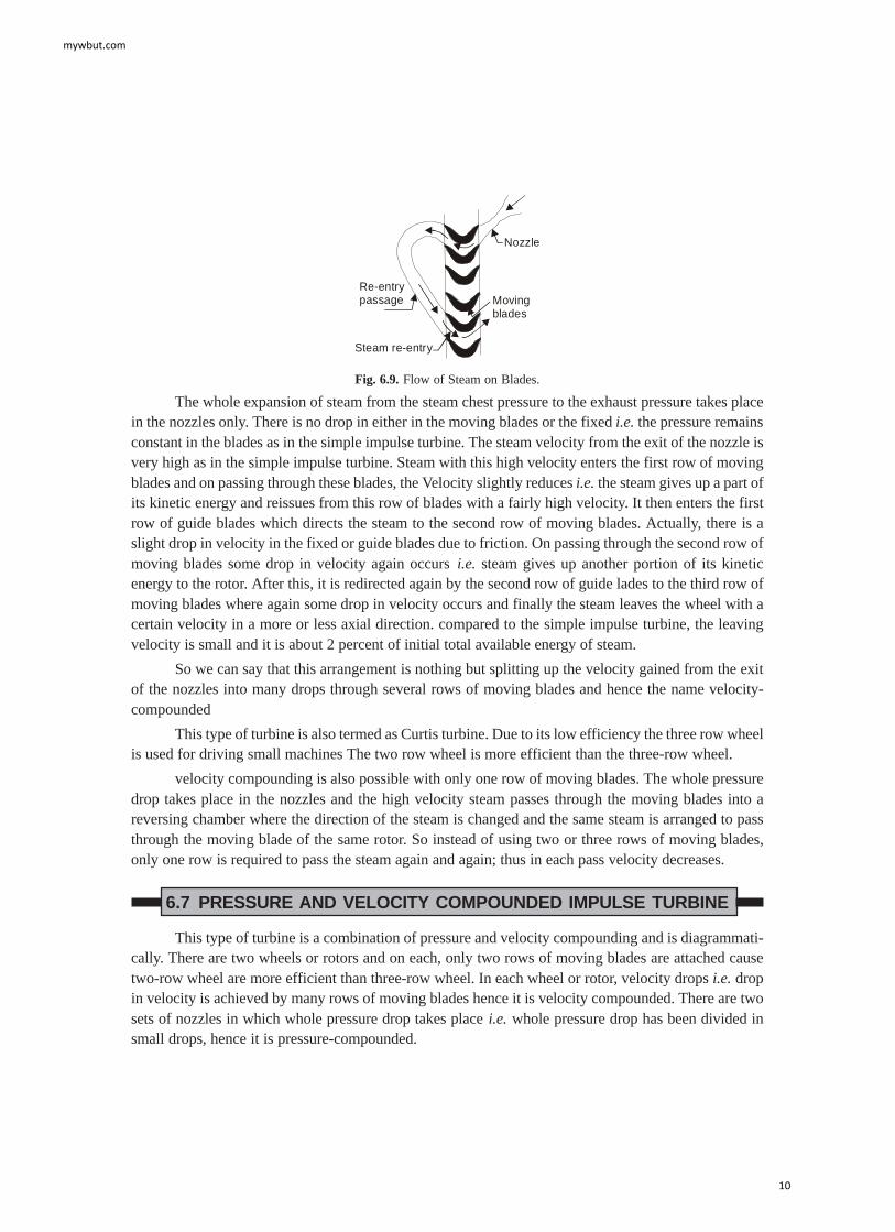
The whole expansion of steam from the steam chest pressure to the exhaust pressure takes placein the nozzles only. There is no drop in either in the moving blades or the fixed i.e. the pressure remainsconstant in the blades as in the simple impulse turbine. The steam velocity from the exit of the nozzle isvery high as in the simple impulse turbine. Steam with this high velocity enters the first row of movingblades and on passing through these blades, the Velocity slightly reduces i.e. the steam gives up a part ofits kinetic energy and reissues from this row of blades with a fairly high velocity. It then enters the firstrow of guide blades which directs the steam to the second row of moving blades. Actually, there is aslight drop in velocity in the fixed or guide blades due to friction. On passing through the second row ofmoving blades some drop in velocity again occurs i.e. steam gives up another portion of its kineticenergy to the rotor. After this, it is redirected again by the second row of guide lades to the third row ofmoving blades where again some drop in velocity occurs and finally the steam leaves the wheel with acertain velocity in a more or less axial direction. compared to the simple impulse turbine, the leavingvelocity is small and it is about 2 percent of initial total available energy of steam.
So we can say that this arrangement is nothing but splitting up the velocity gained from the exitof the nozzles into many drops through several rows of moving blades and hence the name velocity-compounded
This type of turbine is also termed as Curtis turbine. Due to its low efficiency the three row wheelis used for driving small machines The two row wheel is more efficient than the three-row wheel.
velocity compounding is also possible with only one row of moving blades. The whole pressuredrop takes place in the nozzles and the high velocity steam passes through the moving blades into areversing chamber where the direction of the steam is changed and the same steam is arranged to passthrough the moving blade of the same rotor. So instead of using two or three rows of moving blades,only one row is required to pass the steam again and again; thus in each pass velocity decreases.
6.7 PRESSURE AND VELOCITY COMPOUNDED IMPULSE TURBINE
This type of turbine is a combination of pressure and velocity compounding and is diagrammati-cally. There are two wheels or rotors and on each, only two rows of moving blades are attached causetwo-row wheel are more efficient than three-row wheel. In each wheel or rotor, velocity drops i.e. dropin velocity is achieved by many rows of moving blades hence it is velocity compounded. There are twosets of nozzles in which whole pressure drop takes place i.e. whole pressure drop has been divided insmall drops, hence it is pressure-compounded.
mywbut.com
10

In the first set of nozzles, there is some decrease in pressure which gives some kinetic energy tothe steam and there is no drop in pressure in the two rows of moving blades of the first wheel and in thefirst row of fixed blades. Only, there is a velocity drop in moving blades though there is also a slight dropin velocity due to friction in the fixed blades. In second set of nozzles, the remaining pressure drop takesplace but the velocity here increases and the drop in velocity takes place in the moving blades of thesecond wheel or rotor. Compared to the pressure-com-pounded impulse turbine this arrangement wasmore popular due to its simple construction. It is, however, very rarely used now due to its low efficiency.
6.8. IMPULSE-REACTION TURBINE
As the name implies this type of turbine utilizes the principle of im-pulse and reaction both. Sucha type of turbine is diagrammatically shown. There are a number of rows of moving blades attached tothe rotor and an equal number of fixed blades attached to the casing.
Boilersteam
Nozzle
Exhaust
Shaft
MGMNMGMN
Ste
am c
hest
pre
ssur
eIn
itial
ste
am v
eloc
ity
Lost
vel
ocity
Con
dens
er p
ress
ure
Fig. 6.10. Impulse Reaction Turbine.
In this type of turbine, the fixed blades which are set in a reversed manner compared to themoving blades, corresponds to nozzles mentioned in connection with the impulse turbine. Due to therow of fixed blades at the entrance, instead of the nozzles, steam is admitted for the whole circumfer-ence and hence there is all-round or complete admission. In passing through the first row of fixedblades, the steam undergoes a small drop in pressure and hence its velocity somewhat increases. Afterthis it then enters the first row of moving blades and just as in the impulse turbine, it suffers a change indirection and therefore in momentum. This momentum gives rise to an impulse on the blades.
But in this type of turbine, the passage of the moving blades is so designed (converging) thatthere is a small drop in pressure of steam in the moving blades which results in a increase in kineticenergy of steam. This kinetic energy gives rise to reaction in the direction opposite to that of addedvelocity. Thus, the gross propelling force or driving force is the vector sum of impulse and reactionforces. Commonly, this type of turbine is called Reaction Turbine. It is obvious from the Fig. 6.10 thatthere is a gradual drop in pressure in both moving blades and fixed blades.
mywbut.com
11

As the pressure falls, the specific volume increases and hence in practice, the height of blades isincreased in steps i.e. say upto 4 stages it remains constant, then it increases and remains constant for thenext two stages.
In this type of turbine, the steam velocities are comparatively moderate and its maximum value isabout equal to blade velocity. In general practice, to reduce the number of stages, the steam velocity isarranged greater than the blade velocity. In this case the leaving loss is about 1 So 2 per cent of the totalinitial available energy. This type of turbine is used mostly in all power plants where it is great success.An example of this type of turbine is the Parsons-Reaction Turbine. The power plants 30 MW and aboveare all impulse-reaction type.
6.9 ADVANTAGES OF STEAM TURBINE OVER STEAM ENGINE
The various advantages of steam turbine are as follows :
(i) It requires less space.
(ii) Absence of various links such as piston, piston rod, cross head etc. make the mechanismsimple. It is quiet and smooth in operation,
(iii) Its over-load capacity is large.
(iv) It can be designed for much greater capacities as compared to steam engine. Steam turbinescan be built in sizes ranging from a few horse power to over 200,000 horse power in single units.
(v) The internal lubrication is not required in steam turbine. This reduces to the cost oflubrication.
(vi) In steam turbine the steam consumption does not increase with increase in years of service.
(vii) In steam turbine power is generated at uniform rate, therefore, flywheel is not needed.
(viii) It can be designed for much higher speed and greater range of speed.
(ix) The thermodynamic efficiency of steam turbine is higher.
6.10. STEAM TURBINE CAPACITY
The capacities of small turbines and coupled generators vary from 500 to 7500 kW whereas largeturbo alternators have capacity varying from 10 to 90 mW. Very large size units have capacities up to500 mW.
Generating units of 200 mW capacity are becoming quite common. The steam consumption bysteam turbines depends upon steam pressure, and temperature at the inlet, exhaust pressure number ofbleeding stages etc. The steam consumption of large steam turbines is about 3.5 to 5 kg per kWh.
Turbine kW = Generator kW / Generator efficiency
Generators of larger size should be used because of the following reasons:
(i) Higher efficiency.
(ii) Lower cost per unit capacity.
(iii) Lower space requirement per unit capacity. 3.45.1 Nominal rating.
It is the declared power capacity of turbine expected to be maximum load.
mywbut.com
12

6.11 CAPABILITY
The capability of steam turbine is the maximum continuous out put for a clean turbine operatingunder specified throttle and exhaust conditions with full extraction at any openings if provided.
The difference between capability and rating is considered to be overload capacity. A commonpractice is to design a turbine for capability of 125% nominal rating and to provide a generator that willabsorb rated power at 0.8 power factor. By raising power factor to unity the generator will absorb the fullturbine capability.
6.12 STEAM TURBINE GOVERNING
Governing of steam turbine means to regulate the supply of steam to the turbine in order tomaintain speed of rotation sensibly constant under varying load conditions. Some of the methods em-ployed are as follows :
(i) Bypass governing. (ii) Nozzle control governing. (iii) Throttle governing.
In this system the steam enters the turbine chest (C) through a valve (V) controlled by governor.In case of loads of greater than economic load a bypass valve (Vi) opens and allows steam to pass fromthe first stage nozzle box into the steam belt (S).
In this method of governing the supply of steam of various nozzle groups N1, N2, and N3 isregulated by means of valves V1, V2 and V3 respectively.
In this method of governing the double beat valve is used to regulate the flow of steam into theturbine. When the load on the turbine decreases, its speed will try to increase. This will cause the fly barto move outward which will in return operate the lever arm and thus the double beat valve will getmoved to control the supply of steam to turbine. In this case the valve will get so adjusted that lessamount of steam flows to turbine.
6.13 STEAM TURBINE PERFORMANCE
Turbine performance can be expressed by the following factors :
(i) The steam flow process through the unit-expansion line or condition curve.
(ii) The steam flow rate through the unit.
(iii) Thermal efficiency.
(iv) Losses such as exhaust, mechanical, generator, radiation etc.
Mechanical losses include bearing losses, oil pump losses and generator bearing losses. Genera-tor losses include will electrical and mechanical losses. Exhaust losses include the kinetic energy of thesteam as it leaves the last stage and the pressure drop from the exit of last stage to the condenser stage.
For successful operation of a steam turbine it is desirable to supply steam at constant pressureand temperature. Steam pressure can be easily regulated by means of safety valve fitted on the boiler.The steam temperature may try to fluctuate because of the following reasons :
(i) Variation in heat produced due to varying amounts of fuel burnt according to changing loads.
(ii) Fluctuation in quantity of excess air.
(iii) Variation in moisture content and temperature of air entering the furnace.
mywbut.com
13

(iv) Variation in temperature of feed water.
(v) The varying condition of cleanliness of heat absorbing surface.
The efficiency of steam turbines can be increased:
(i) By using super heated steam.
(ii) Use of bled steam reduces the heat rejected to the condenser and this increases the turbineefficiency.
6.14 STEAM TURBINE TESTING
Steam turbine tests are made for the following:
(i) Power
(ii) Valve setting
(iii) Speed regulation
(iv) Over speed trip setting
(v) Running balance.
Steam condition is determined by pressure gauge, and thermometer where steam is super heated.The acceptance test as ordinarily performed is a check on (a) Output, (b) Steam rate or heat consump-tion, (c) Speed regulation, (d) Over speed trip setting.
Periodic checks for thermal efficiency and load carrying ability are made. Steam used should beclean. Unclean steam represented by dust carry over from super heater may cause a slow loss of loadcarrying ability.
Thermal efficiency of steam turbine depends on the following factors:
(i) Steam pressure and temperature at throttle valve of turbine.
(ii) Exhaust steam pressure and temperature.
(iii) Number of bleedings.
Lubricating oil should be changed or cleaned after 4 to 6 months.
6.15 CHOICE OF STEAM TURBINE
The choice of steam turbine depends on the following factors :
(i) Capacity of plant
(ii) Plant load factor and capacity factor
(iii) Thermal efficiency
(iv) Reliability
(v) Location of plant with reference to availability of water for condensate.
6.16 STEAM TURBINE GENERATORS
A generator converts the mechanical shaft energy it receive from the turbine into electrical en-ergy. Steam turbine driven a.c. synchronous generators (alternators) are of two or four pole designs.These are three phase measuring machines offering economic, advantages in generation and transmis-
mywbut.com
14

sion. Generator losses appearing as heat must be constantly removed to avoid damaging the windings.Large generators have cylindrical rotors with minimum of heat dissipation surface and so they haveforced ventilation to remove the heat. Large generators generally use an enclosed system with air orhydrogen coolant. The gas picks up the heat from the generator any gives it up to the circulating water inthe heat exchanger.
6.17 STEAM TURBINE SPECIFICATIONS
Steam turbine specifications consist of the following:
(i) Turbine rating. It includes :
(a) Turbine kilowatts
(b) Generator kilovolt amperes
(c) Generator Voltage
(d) Phases
(e) Frequency
(f) Power factor
(g) Excitor characteristics.
(ii) Steam conditions. It includes the following:
(a) Initial steam pressure, and Temperature
(b) Reheat pressure and temperature
(c) Exhaust pressure.
(iii) Steam extraction arrangement such as automatic or non-automatic extraction.
(iv) Accessories such as stop and throttle valve, tachometer etc.
(v) Governing arrangement.
SOLVED EXAMPLES
Example 1. In an impulse steam turbine, steam is accelerated through nozzle from rest. It entersthe nozzle at 9.8 bar dry and saturated. The height of the blade is 10 cm and the nozzle angle is 15°.Mean blade velocity is 144 m/s. The blade velocity ratio is 0.48 and blade velocity coefficient is 0.97.Find:
(1) Isentropic heat drop.
(2) Energy lost in the nozzles and in moving blades due to friction.
(3) Energy lost due to finite velocity of steam leaving the stage.
(4) Mass flow rate.
(5) Power developed per stage.
(6) Diagram and stage efficiency. Take: Nozzle efficiency = 92%
Blade angles at inlet = Blade angles at out let Speed = 3000 rev/min
Solution. V.R. = 1
V
Vb = 0.48
mywbut.com
15

Now, Vb = 144 m/s ; V1 = 144 = 300 m/s 0.48
V2/2 × 103 = Isentropic heat drop × Nozzle efficiency
(1) Isentropic heat drop = 2
3
300
(2 10 0.92)× × = 48.9 kJ/kg
(2) Energy lost in nozzles = Isentropic heat drop × (1 – ηn) = 48.9 × (1 – 0.92)
= 3.91 kJ/kg
Energy lost in moving blades due to friction = 2
1 23
V V
(2 10 )
−×
r r kJ/kg
Now Vr0 = 0.97 × Vr1
Vb
Vt1
EA
C D
Vr 2
Vr 1
V1
Bα φ θ
V0 Va 1
To draw velocity triangles, AB = Vb = 144 m/s, α = 15°, V1 = 300 m/s With this triangle ABD canbe completed.
Measure Vr1, and θ, Vr1 = 168 m/s, θ = 29°
Vr0 = 0.97 × 168 = 163 m/s, and θ = 29° .
Velocity triangle ABC can be completed
Energy lost in moving blades due to friction = 2 2
3
168 163
(2 10 )
−×
= 0.83 kJ/kg 2 × 10³
(3) Energy lost due to finite velocity of steam leaving the stage 2
03
V
(2 10 )×
From velocity triangle, V0 = 80 m/s
Energy lost = 2
3
80
(2 10 )×
(4) Vb = πDn/60
144 = π × D × 3000
60
D = 0.917 m
mywbut.com
16

Area of flow, A = πDh = 3.14 * 0.917 * 10
100 = 0.288 m2
Now from steam table, for steam dry and saturated at 9.8 bar,
Vs = 0.98 m3/kg
Va1 = 77.65 m/s from velocity triangles
Mass flow rate = Va1 × A
Vs = 77.65 *
0.288
0.198 = 112.95 kg/s
(5) Power = m × Vb × (Vt1 – Vt0) kW
from velocity triangle Vt1 – Vt0 = 288 m/s
power = 112.95 × 144 × 288
1000 = 4682 kW
(6) Diagram efficiency = 2 × Vb × 1 02
1
(V V )
Vt t−
= 92.16
stage efficiency = diagram efficiency × ηn = 0.9216 × 0.92
Example 2. An impulsive stage of a steam turbine is supplied with dry and saturated steam at14.7 bar. The stage has a single row of moving blades running at 3600 rev/min. The mean diameter ofthe blade disc is 0.9 m. The nozzle angle is 15° and the axial component of the absolute velocity leavingthe nozzle is 93.42 m/s. The height of the nozzles at their exit is 100 mm. The nozzle efficiency is 0.9 andthe blade velocity co-efficiency is 0.966. The exit angle of the moving blades is 2° greater than at theinlet. Determine:
(1) The blade inlet and outlet angles.
(2) The isentropic heat drop in the stage.
(3) The stage efficiency.
(4) The power developed by the stage.
Solution. Mean blade velocity, Vb = DN
60
π = 3.14 × 0.9 ×
3600
60 = 169.65 m/s
α = 15° ; Va1 = 93.42 m/s
Now Va1 = V1 sin α ; V1 = 1V
sina
α = 360.95 m/s
With this, inlet velocity triangle can be completed
From there: θ = 29.5° Vr1 = 202.5 m/s
ϕ = 29.5 + 2 = 31.5 ; Vr0 = 0.966 × Vr1 = 195 m/s
With this, the outlet velocity triangle can be completed
θ = 29.5°, ϕ = 31.5°
Now for dry and saturated steam at 14.7 bar; Vs = 0.1392 m3/kg
mywbut.com
17

Vb
Vt1
EA
C D
Vr 0
Vr 1
V1
Bα φ θ= 31.5° = 29.5
V = V0 a 0Va 1
m = A × 1V
Va
s = πDh × 1V
Va
s = 196.82 kg/s
power = m × Vb × 1 0( )
1000t tV V−
kW
from velocity triangle
(Vt1 – Vt0) = 348.65 m/s
power = 196.82 × 169.65 × 348.65
1000 = 11637.6 kW
Blade efficiency = 2 × vb × 1 02
1
(V V )
Vt t−
ηb = 2 × 169.64 × 2
348.65
(360.95)
= 90.79 %
ηs = ηb × ηn = 0.9079 × 0.9 = 0.817
heat drop for the stage = 15822.7
0.817 = 14244.3 kJ/s
= 72.37 kJ/kg
Example 3. In a simple steam Impulse turbine, steam leaves the nozzle with a velocity of 1000 m/s atan angle of 20° to the plane of rotation. The mean blade velocity is 60% of velocity of maximum effi-ciency. If diagram efficiency is 70% and axial thrust is 39.24 N/kg of steam/sec, estimate:
(1) Blade angles.
(2) Blade velocity co-efficient.
(3) Heat lost in kJ in friction per kg.
Solution. for max. efficiency,
V.R = 1
V
Vb = cos
2
α
mywbut.com
18

1
V
Vb = cos
20
2
° = 0.47
For the present problem = Vb = 0.6 × 0.47 × V1
= 282 m/s
α = 20°, V1 =1000 m/s
with this, the inlet velocity triangle can be completed. From here
Vr1 = 740 m/s, Va1 = 350 m/s, Vt1 = 940 m/s
Vb
EA
C D
Vr0
Vr 1
V1
B
β φ θ
Va 0Va 1
α = 20°
V0
= 1000 m/s
Vt1
Vr0
now axial thrust = 39.24 = Va1 – Va0
Va0 = 350 – 39.24 = 310.76 m/s
Now diagram efficiency = 0.70 = 2 × Vb × 1 02
1
(V V )
Vt t−
From here, Vt0 = 301 m/s
Now the outlet velocity can be drawn
From here
θ = 280, ϕ = 28°, Vr0 = 660 m/s
Blade velocity co-efficient 0
1
V
Vr
r
= 660/740 = 0.89
Heat lost in kJ in friction per kg per s.
= 2 2
1 0V V
2 1000
−×
r r = 2 2(740) (660)
2000
− = 55.94 kJ/kg/s
Example 4. A reaction steam turbine runs at 300 rev/min and its steam consumption is 16500kg/hr. The pressure of steam at a certain pair is 1.765 bar (abs.) and its dryness fraction is 0.9. and thepower developed by the pair is 3.31 kW. The discharge blade tip angel both for fixed and moving bladeis 20° and the axial velocity of flow is 0.72 of the mean moving blade velocity. Find the drum diameterand blade height. Take the tip leakage as 8%, but neglect area blocked by blade thickness.
Solution. Vb = DN
60
π = 15.7 D m/s
mywbut.com
19

Steam flow rate through blades = 0.92 × 16500
3600 = 4.216 kg/s
Power output = 3.31 = m × Vb × 1 0(V V )
1000t t−
(Vt1 – Vt0) = 3.31 × 1000
(4.216 15.7 D)× = 50/D m/s
Flow velocity
Va1 = Va0 = 0.72 Vb = 11.30D m/s
From velocity triangle (Vt1 – Vt0) = 2 × Va cot 20° – Vb
= 2 × 11.30 D × 2.7475 – 15.7D
= 46.415 D m/s
50
D = 46.415 D
D = 1.03 m
Flow velocity Va = 11.30 × 1.03 = 11.64 m/s
Now Vs (at 1.765 bar and 0.9 dry, from steam table)
= 0.9975 × 0.9 m3/Kg
A = πdh = m × V
Vs
a
h = 4.216 × 0.9957 × 0.9
11.64 × π × 1.03
= 0.1 m
Example 5. At a particular ring of a reaction turbine the blade speed is 67 m/s and the flow ofsteam is 4.54 kg/s, dry saturated, at 1.373 bar. Both fixed and moving blades have inlet and exit anglesof 35° and 20° respectively.
Determine:
(a) Power developed by the pair of rings.
(b) The required blade height which is to be one tenth of the mean blade ring diameter.
(c) The heat drop required by the pair if the steam expands with an efficiency of 80%.
Solution. Vb = 67 m/s, m = 4.54 kg/s ϕ = α = 20°, θ = β = 35°
With this given data, the velocity triangles can be drawn From the velocity triangles,
Vtl – Vto = 212 m/s
mywbut.com
20

Vb
EA
C D
Vr 0
Vr 1
V1
Va 0Va 1
V0
Vt 1Vr 0
B
35° 35°20° 20°F
Power = m × Vb × 1 0(V V )
1000t t−
kW
= 4.54 × 67 × 212
1000 = 64.47 kW
at 1.373 bar, dry saturatedVs = 1.259 m3/Kg (from steam table)
Now m = πD × D × V
Va
s × 10
From velocity triangle,Va = 50 m/s
D2 = 4.54 × 1.259 × 10
50×p = 0.3
D = 0.5477 m
h = 5.477 cm
Heat drop required = 74.47
0.8 = 80.58 kJ/kg.
EXERCISE
1. Steam is supplied to a turbine at a pressure of 58.42 bar abs and tetnperature of 440°C. It isexpanded in a H.P. turbine to 6.865 bar abs., the internal efficiency of the turbine being 0.85.The steam is then reheated at constant pressure upto 300°C. Its is then expanded to 0.049 barabs. In L.P. turbine having internal efficiency of 0.80. If the mechanical efficiency of theturbine is 98% and alternator efficiency is 96%, calculate the amount of steam generated bythe boiler per kWh output. [Ans. 3.68 kg/hr]
2. A steam power plant working on regenerative heating cycle utilizes steam at 41.2 bar and400°C and the condenser pressure is 0.944 bar vacuum. After expansion in the turbine to 4.90bar, a part of steam is extracted from the turbine for heating feed water from condenser in theopen heater. Draw the cycle on T-0 diagram and find thermal efficiency of the plant. Assumethe heat drop to be isentropic and the atmospheric pressure may be taken as 1.013 bar.
[Ans. 38.89%]
mywbut.com
21

3. Steam at pressure of 30.23 bar and 400°C temperature is supplied to a steam turbine and isexhausted at a pressure of 0.06865 bar. A single bleed is taken between the H.P. cylinder andL.P. cylinder of the turbine at 2.45 bar for regenerative feed heating. The isentropic efficiencyfor both the cylinders of the turbine is 85%. The temperature of the bleed condensate comingout of the heat exchanger is 10°C lower than the temperature of the bled steam. Determine:
(a) Amount of bled steam per kg of steam supplied to the steam turbine.
(b) The thermal efficiency of the plant.
Consider no losses and pump work as negligible. Let the condensate coming out from theheat exchanger and condenser be led to the hot well. [Ans. 0.158 kg/kg of steam, 32%]
4. In a condenser test, the following observations were made:
Vacuum = 69 cm of Hg
Barometer = 75 cm of Hg
Mean temperature of condenser = 35°C
Hot well temperature = 28°C
Amount of cooling water = – 50,000 kg/hr
Inlet temperature = 17°C
Outlet temperature = 30°C
Amount of condensate per hour = 1250 kg
Find
(a) the amount of air present per m3 of condenser volume.
(b) the state of steam entering the condenser.
(c) the vacuum efficiency .
R for air = 287 J/kgK. [Ans. 0.0267 kg, 0.883, 97.48%]
5. In a power plant, steam at a pressure of 27.46 bar abs. and temperature 370°C is supplied bythe main boilers. After expansion in the H.P. turbine to 5.$84 bar abs., the steam is removedand reheated to 370°C. Upon completing expansion in L.P. turbine, the steam is exhausted ata pressure of 0.0392 bar abs. Find the efficiency of the cycle with and without reheating.
[Ans. 37.19%, 36.38%]
6. A fuel contains the following percentage of combustibles by mass C: 84%, H2 : 4.1 %. If theair used from burning of coal in a boiler is 16.2 kg per kg of fuel, find the total heat carriedaway by dry flue gases if they escape at 300°C. The specific heats of CO2, OZ, NZ are 0.892,0.917 and 1.047 respectively. Find the minimum amount of air required from the completecombustion of 1 kg of this fuel and the excess O2 supplied. [Ans. 4806.68 kJ, 11.16, 1.158]
7. A sample of coal has the percentage analysis by mass, C-85%, H-5%, incombustible-10%. Ina combustion chamber, the coal is burnt with a quantity of air 50% in excess of that theoreti-cally required for complete combustion. Obtain the volumetric composition of dry flue gases.When final temperature of flue gases is 307°C and boiler house temperature is 27°C, estimatethe maximum quantity of heat available for steam raising per kg of coal. Take CP for dry fluegases as 1.005 and assume that the total heat of vapour in flue gases as 2683.87 kJ/kg. TheC.V. of coal is 32784.2 kJ/kg.
mywbut.com
22