chap3_datums
DESCRIPTION
gd&TTRANSCRIPT
Geometric Dimensioning and Tolerancing
Chapter 3, Datums

EML 2023Department of Mechanical and Aerospace Engineering 2
GDT
1. Establish a reference coordinate system.
2. Tell me where ‘perfect’ is.
3. Tell me how far off from ‘perfect’ is allowed.

EML 2023Department of Mechanical and Aerospace Engineering 3
Introduction
• Datums are nothing more and nothing less than the physical features of parts from which to make repeatable measurements.
• These features are considered theoretically exact.
• Datums define a coordinate system from which to measure everything.
• Datums are usually a plane, a line, or a point.
• We will need to label the datums on our drawing so that the part inspector will know from where to measure.

EML 2023Department of Mechanical and Aerospace Engineering 4
Datum Feature Symbol
• Datum Feature Symbol

EML 2023Department of Mechanical and Aerospace Engineering 5
Three-Plane Concept• define primary, secondary,
and tertiary datum planes
• the primary datum is the one that functionally is usually the most critical feature or surface of the part
• the primary datum feature of the part will make contact with the theoretical datum plane in a minimum of three points

EML 2023Department of Mechanical and Aerospace Engineering 6
Three-Plane Concept• the secondary datum plane
is to the primary datum
• secondary datum feature is the one that functionally is the 2nd most critical feature or surface of the part
• 2 point minimum contact
EML 2023Department of Mechanical and Aerospace Engineering 7
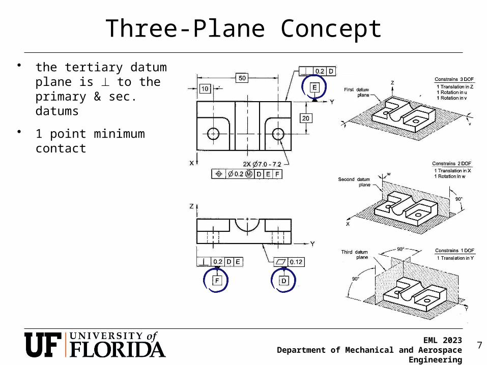
Three-Plane Concept• the tertiary datum plane is
to the primary & sec. datums
• 1 point minimum contact

EML 2023Department of Mechanical and Aerospace Engineering 8
Three-Plane Concept - Circular
• circular parts also require a three-plane concept for repeatable orientation
• the primary datum is usually one flat surface of the part,• defines a datum axis along the center of cylinder
should bea construction line(or omitted)
should havea center line

EML 2023Department of Mechanical and Aerospace Engineering 9
Three-Plane Concept - Circular
• datum A defines an axis along the center of the cylinder
EML 2023Department of Mechanical and Aerospace Engineering 10
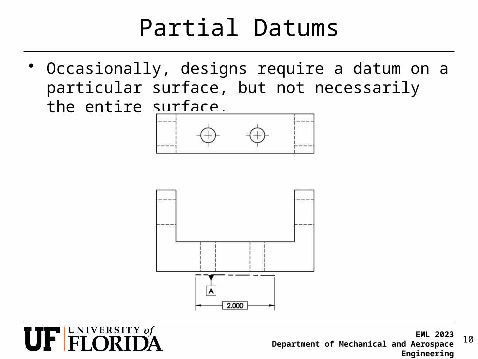
Partial Datums
• Occasionally, designs require a datum on a particular surface, but not necessarily the entire surface.
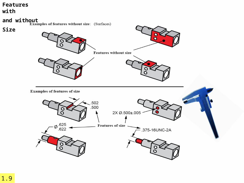
Features with
and without
Size
1.9

Datum features H and L are mated with atheoretical perfect plane contacting thehigh points of the datum feature.
Theory
0.2
M-10x1.25
5H7(5/5.012)±0.215.9
25±0.3
6±0.252X
12.7±0.1
±0.325
LL
H
Physical
Datum features H and L are mated on the high points of the manufacturing or inspection equipment
6.15
Establishing Datums from Primary Plane Surfaces

Physical datum feature simulator(surface plate orprocessing equipment)
WorkpieceDatumfeature
Physical
6.15
Establishing Datums from Primary Plane Surfaces
W O R K P IE C E
S U R F A C E
Theoretical datum plane Magnified View
Simulated datum plane
Datum feature simulator
Datum feature
Tool and gage variation

0.2
P
M-10x1.25
5H7(5/5.012)±0.215.9
25±0.3
M2 SURFACES
6±0.252X
12.7±0.1
±0.325
S 17±0.02
L
K
H
N
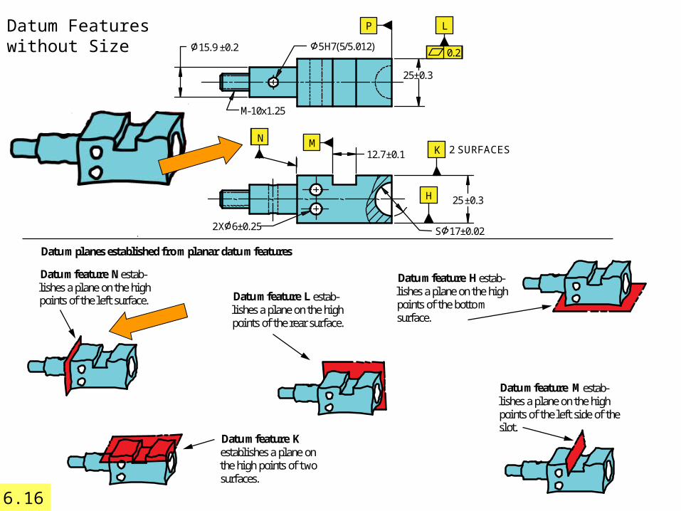
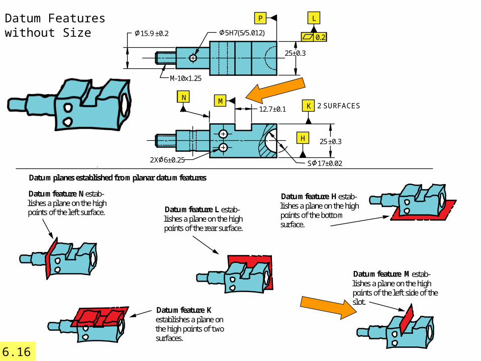
Datum planes established from planar datum features
Datum feature M estab-lishes a plane on the highpoints of the left side of theslot.
Datum feature Kestablishes a plane onthe high points of twosurfaces.
Datum feature H estab-lishes a plane on the highpoints of the bottomsurface.
Datum feature L estab-lishes a plane on the highpoints of the rear surface.
Datum feature N estab-lishes a plane on the highpoints of the left surface.
Datum Features without Size
6.16

0.2
P
M-10x1.25
5H7(5/5.012)±0.215.9
25±0.3
M2 SURFACES
6±0.252X
12.7±0.1
±0.325
S 17±0.02
L
K
H
N
Datum planes established from planar datum features
Datum feature M estab-lishes a plane on the highpoints of the left side of theslot.
Datum feature Kestablishes a plane onthe high points of twosurfaces.
Datum feature H estab-lishes a plane on the highpoints of the bottomsurface.
Datum feature L estab-lishes a plane on the highpoints of the rear surface.
Datum feature N estab-lishes a plane on the highpoints of the left surface.
Datum Features without Size
6.16
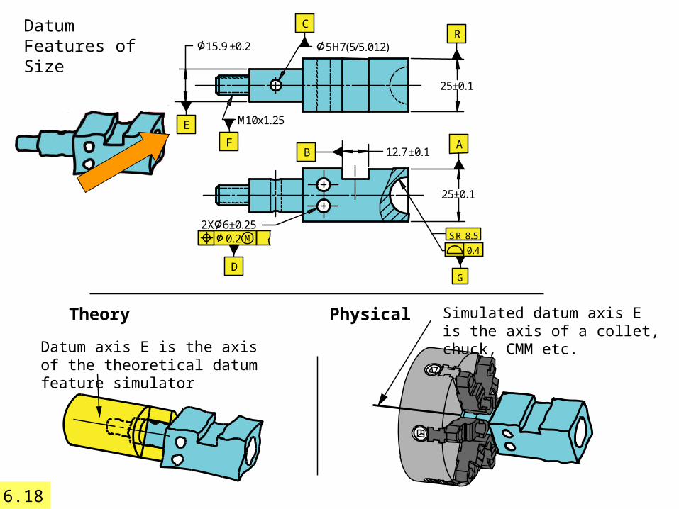
Datum axis E is the axis of the theoretical datum feature simulator
Theory Physical Simulated datum axis E is the axis of a collet, chuck, CMM etc.
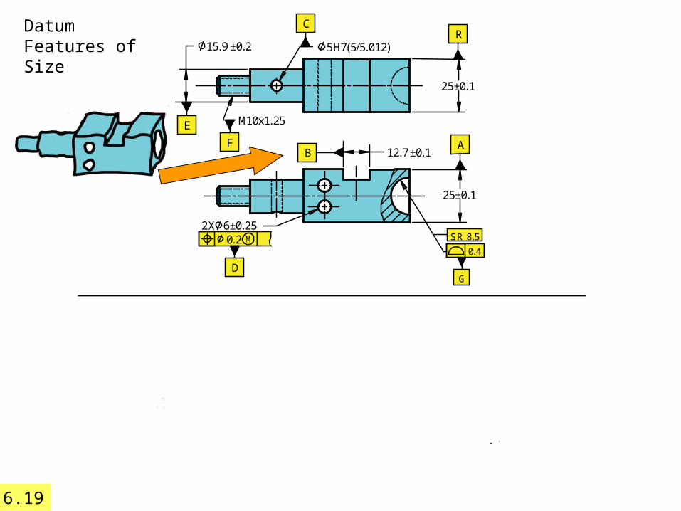
Datum Features of Size
6.18
0.2
D
M
B
6±0.252X
12.7±0.1
25±0.1
SR 8.5
C
F A
R
E M10x1.25
5H7(5/5.012)±0.215.9
25±0.1
0.4
G
0.2
D
M
B
6±0.252X
12.7±0.1
25±0.1
SR 8.5
C
F A
R
E M10x1.25
5H7(5/5.012)±0.215.9
25±0.1
0.4
G
Datum Features of Size
6.19

0.2
D
M
B
6±0.252X
12.7±0.1
25±0.1
SR 8.5
C
F A
R
E M10x1.25
5H7(5/5.012)±0.215.9
25±0.1
0.4
G
Sim ulated datum center plane B is
the center plane of the gage block.
PhysicalDatum center plane B is
the center plane of thedatum feature simulator.
Theory
Datum Features of Size
6.19
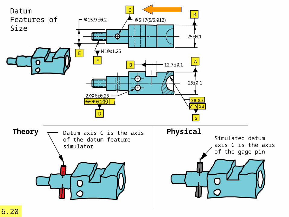
Datum axis C is the axis of the datum feature simulator
TheorySimulated datum axis C is the axis of the gage pin
Physical
Datum Features of Size
6.20
0.2
D
M
B
6±0.252X
12.7±0.1
25±0.1
SR 8.5
C
F A
R
E M10x1.25
5H7(5/5.012)±0.215.9
25±0.1
0.4
G
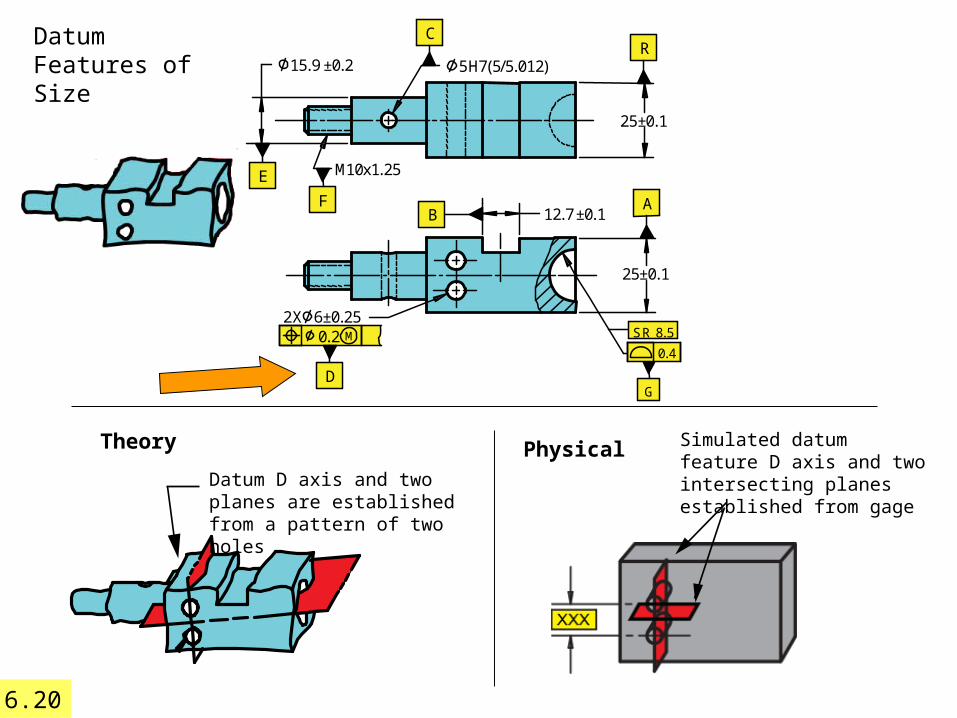
Datum D axis and two planes are established from a pattern of two holes
Theory
Datum Features of Size
6.20
0.2
D
M
B
6±0.252X
12.7±0.1
25±0.1
SR 8.5
C
F A
R
E M10x1.25
5H7(5/5.012)±0.215.9
25±0.1
0.4
G
Simulated datum feature D axis and two intersecting planes established from gage
Physical

K
M10x1.25
5H7(5/5.012)±0.215.9
25±0.2
B
M
25±0.2
12.7±0.1
2X ±0.256
S 17±0.2
R
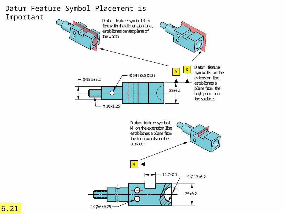
Datum feature symbol Bin line with the dimensionline establishes the centerplane of the slot.
Datum feature symbolM on the extension lineestablishes a plane fromthe high points on thesurface.
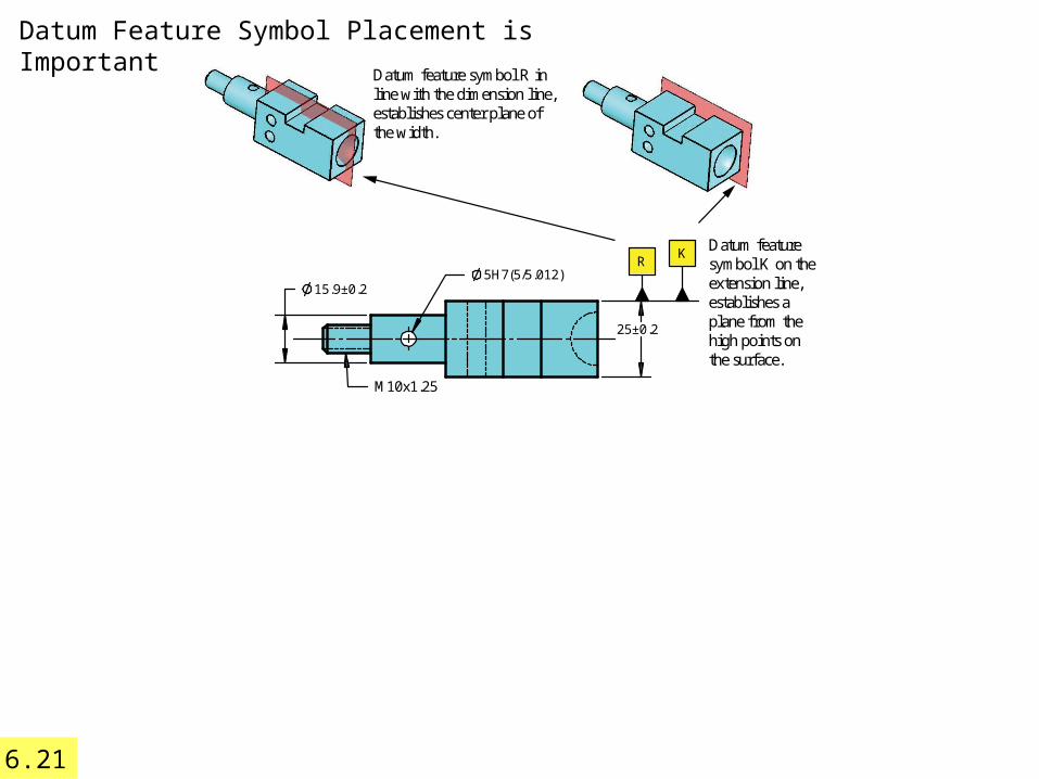
Datum feature symbol R inline with the dimension line,establishes center plane ofthe width.
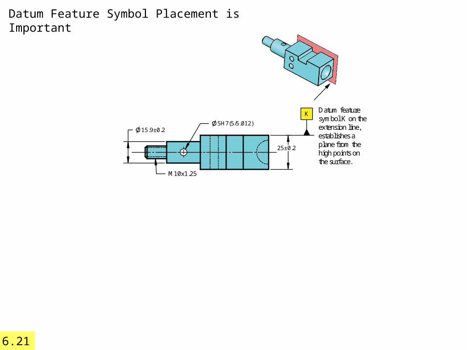
Datum featuresymbol K on theextension line,establishes aplane from thehigh points onthe surface.
Datum Feature Symbol Placement is Important
6.21

K
M10x1.25
5H7(5/5.012)±0.215.9
25±0.2
B
M
25±0.2
12.7±0.1
2X ±0.256
S 17±0.2
R
Datum feature symbol Bin line with the dimensionline establishes the centerplane of the slot.
Datum feature symbolM on the extension lineestablishes a plane fromthe high points on thesurface.
Datum feature symbol R inline with the dimension line,establishes center plane ofthe width.
Datum featuresymbol K on theextension line,establishes aplane from thehigh points onthe surface.
Datum Feature Symbol Placement is Important
6.21

EML 2023Department of Mechanical and Aerospace Engineering 33
Evaluationspecified
dimension , orientation
planes, axis, center lines, edges, points, areas
no
three
90circle
sizeXX
Xtolerance
X
conveyX
rocking
X