chapter 1 introduction - core
TRANSCRIPT

1
CHAPTER 1
INTRODUCTION
1.1 Background of Study
A gas turbine is a rotary mechanical device that extracts energy and converts it into
useful work [1][4]. According to H.I.H. Saravanamuttoo et al. [1], it is consist of an
upstream rotating compressor coupled to a downstream turbine, and a combustion
chamber in between. In the combustor, energy is added to the gas stream where fuel
is mixed with air and ignited. The combustion of the fuel will raise the temperature
in the high pressure environment of the combustor. Then, the product of the
combustion will be forced into the turbine section. In the turbine section, the high
volume and velocity of the gas flow will be directed through a nozzle over the
turbines’ blades, turning the turbine which powers the compressor and produce a
certain net power. A reduction in the temperature and pressure of the exhaust gas
will result to the energy given up to the turbine [1][4].
Figure 1.1: Basic principles of Gas Turbine; Brayton Cycle [1]
One of the important equipment in a gas turbine is the turbine blade [2][3]5]. Boyce
et al. [2] claimed that turbine blades are expose to thermal and centrifugal stress
which results a certain deformation and microstructure change as the usage time
increases. This deformation is called creep. Microstructure change and creep affect

2
the turbine performance or may lead to catastrophic failure. Consequently, the blades
life is limited. The search for a perfect method to predict the remaining creep life of
used gas turbines blades has lead to the development of many equations used to
extrapolate the results from High Temperature Creep Testing experiment, namely
Stress-Rupture test [6][7]. Stress-Rupture test is the sudden and complete failure of a
material held under a definite constant load for a given period of time at a specific
temperature. Walls et al. [11] stated that one of the equations is the Life Fraction rule
proposed by Robinson [11]. This equation will give approximation on the remaining
creep life of the service-exposed turbine blades [11]. Thus, it will be easier to predict
the remaining useful life. Furthermore, Walls et al. [11] also stated that the Stress-
Rupture test result will be further develop to obtain the Larson-Miller parameter
[11]. The Larson-Miller parameter will be compared with the one given by the
manufacturer to draw a comparison. Thus, the different information will be
evaluated. Other than that, Smith et al. [8] claimed that there will be microstructure
changes on blade material after exposed to high stress and temperature over a long
period of time. This is the main reason why the blades has limited service life. The
difference between the unexposed and exposed service blades microstructure
arrangement can be observed by using the Field Emission Scanning Electron
Misroscope (FESEM) [8].
Figure 1.2: Turbine Blade [1]

3
1.2 Problem Statement
Materials used for high temperature purpose such as gas turbine blade will reach a
certain deformation (creep) period after regularly use. This leads to a certain lifetime
service of the components because of the limited service life of the material. Usually,
the manufacturer will specify the expected useful life of the gas turbine blades.
However, not all blades are deformed at the end of the expected useful life period. If
those blades still can be used, replacing them will be a waste of capital. So, if it is
possible to predict the remaining creep life of service-exposed blades, we can reuse
thus saving the cost on new replacement blades. The samples were supplied by
Malaysia Liquefied Natural Gas (MLNG) Labuan.
Figure 1.3: GE Gas Turbine blades from MLNG, Labuan
1.3 Objective of the Study
The main objectives of this study are:
To determine the remaining creep life of a used gas turbine blades using
Larson-Miller parameter and Life Fraction rule
To investigate the microstructure change of used gas turbine blades at
different service times

4
1.4 Scope of Study
This study will focus on:
Samples preparation for the blades’ microstructure examination
Examination of the blades’ microstructure using Field Emission Scanning
Electron Microscope (FESEM)
Determination of the remaining creep life of used gas turbine blades
using Larson-Miller parameter and Life Fraction Rule
1.5 Relevancy of the Project
This project is relevant to the author as a Mechanical Engineering student
who had completed courses related to industry such as Thermodynamics I,
Thermodynamics II, Heat Transfer, and Energy Conversion and
Management. Furthermore, it is very important to predict the remaining creep
life of used gas turbine blades. This is because the capital cost could be saves
on new blade replacement if it still can be use. Hopefully, this project will be
beneficial financially for MLNG Labuan.
1.6 Feasibility of the Project within the Scope and Time Frame
There were two semesters of studies given to complete the Final Year
Project. There are Final Year Project I and Final Year Project II for each
semester. The time given was about eight months for the author to complete
and document the project. During Final Year Project I, the author spent most
of the time to do research on journals that are related to the project.
Meanwhile, during Final Year Project II, the author has conducted the major
part of the project which is the laboratory test for designed experiment. After
all, the author will finally implement all the theories and knowledge he
obtained from the laboratory research and provide conclusion for the project
that will be finalize in a Final Year Project Report.

5
CHAPTER 2
LITERATURE REVIEW
2.1 Gas Turbine
The Table 2.1 shows the chronology of Gas Turbine development:
Table 2.1: Gas Turbine chronology [2]

6
2.2 Gas Turbine System
The gas turbine cycle is explained by the Brayton Cycle. The characteristics of the
operating cycle are shown on the pressure-volume map and the temperature-entropy
map. The gas turbine, as a continuous flow machine, is best described by the first
law of thermodynamics. The 1st Law of Thermodynamics simply states that energy
can be neither created nor destroyed (conservation of energy). Thus power
generation processes and energy sources actually involve conversion of energy from
one form to another, rather than creation of energy from nothing [1][2][4][5].
Figure 2.1: Brayton Cycle [1][2]
From Figure 2.1,
Process 1-2: Isentropic compression (in compressor)
Process 2-3: P = Constant heat addition
Process 3-4: Isentropic Expansion (in turbine)
Process 4-1: P = Constant heat rejection

7
2.3 Materials for Gas Turbine Blades
Gas turbine blades are subjected to a very rough environment inside a gas turbine.
Factors such as high temperature, high stresses and a potentially high vibration
environment affect the performance of the turbine blades. All these factors stated can
lead to blade failures, which also can lead to engine failure and that is the main
reason why the turbine blades are carefully designed. One of the important factors in
manufacturing the early jet engines was the performance of the available materials
especially for hot section such as turbine blade. One of the earliest materials used
was Nimonic, for British Whittle engines [4][5].
Figure 2.2: Nimonic [4][5]
Furthermore, the development of super alloys in the 1940s and the existence of new
processing ways such as vacuum induction melting in the 1950s greatly improved
the temperature capability of turbine blades. Then, the introduction of methods such
as hot isostatic pressing further improved the alloys used as a material for turbine
blades. Nowadays, turbine blades often use nickel-based superalloys that incorporate
cobalt, rhenium and chromium [4][5].
Figure 2.3: Nickel-based superalloys [4][5]

8
Apart from alloy improvements, a major achievement was the development of single
crystal (SC) and directional solidification (DS) production methods. Those
introduced method really helpful in increasing the strength against fatigue and creep
by aligning the grain boundaries in one direction (DS) or by eliminating grain
boundaries all together (SC) [4][5].
Most turbine blades were manufactured by investment casting. One of the important
processes involved in investment casting is making a precise negative die of the
blade shape that is filled with wax to form the blade shape. A ceramic core in the
shape of the passage will be inserted into the middle if the blade is hollow. A heat
resistant material will be used to coat the wax blade to make a shell, and then that
shell will be filled with the blade alloy. If the middle of the blade is filled with
ceramic core, it will be dissolved in a solution that leaves the blade hollow. The
blades will be further coated with an TBC followed by the formation of cooling
holes, that result in a complete turbine blade [4][5].
Figure 2.4: Investment Casting [4][5]

9
2.4 Microstructural aspects of the Nickel base Superalloys components
Superalloys were developed since the second quarter of the 20th century as materials
for elevated temperature applications. It can be divided in three main groups: nickel
base superalloys, cobalt base superalloys and iron base superalloys. The nickel base
alloys are the most widely used. In these alloys, the presence of chromium is
essential to assure high-temperature oxidation resistance, whereas other alloying
elements are important to guarantee high-temperature strength, especially creep
resistance [11].
Other elements such as aluminum and titanium, enable the precipitation of the c0
phase (Ni3(Al,Ti)) during heat treatment, which strengthens the face centered cubic
matrix (c phase). The c0 precipitates are usually very fine and dispersed and they can
be seen only through electron microscopy. Another kind of phase that is also very
important for the mechanical properties of nickel base superalloys is carbides. These
particles are present in these alloys for two main reasons: because it is very difficult
to remove carbon during refining and because carbon is added on purpose to form
carbides, which improve creep properties [12].
However, the amount and distribution of carbides must be carefully controlled,
otherwise they can cause the occurrence of cracks. The amount of other alloying
elements (Cr, Mo, W,) must be high enough to obtain good mechanical and
corrosion properties, but low enough to avoid the excessive formation of
intermetallic phases which can lead to embrittlement [11,12].

10
Based on Figure 2.5 and 2.6, it can be seen that the overheated sample 1 presented
aligned and connected carbides, which formed preferential sites for nucleation and
propagation of cracks. Another important observation was the heterogeneous
distribution of phase c0 precipitates, whose segregation is harmful to the mechanical
properties of the material. These two factors explain the failure of this component.
On the other hand, sample 2, subjected to normal operational conditions, shows a
much less heterogeneous matrix than sample 1, not only in relation to c0 precipitates,
but also carbides, which, in this case, are much more dispersed throughout the c
matrix [11,12].
Figure 2.5: Material subjected to overheating [11][12]
Figure 2.6: Material not subjected to overheating [11][12]

11
2.5 Creep (Deformation)
Creep is known as the tendency of a material to change slowly or deform
permanently under the effect of stresses. It is usually affected by a long term
exposure to high levels of stress that are below the yield strength of a certain
material [3][6][8]. Yield strength is the stress at which a material begins to deform
plastically. Below to the yield strength, the material will return to its original shape
when the applied stress is removed (deform elastically) but once the yield strength is
passed, some fraction of the deformation will be non-reversible and permanent [7].
Creep is always increasing with temperature. Creep will occur fast in materials that
are subjected to heat for a long period, and near its melting point [6].
The rate of creep deformation is a function of the material properties, exposure time,
applied structural load and exposure temperature. Depending on the magnitude of the
applied stress and its period, the failure may become so large that a component can
no longer perform its function. For instance, the creep of a turbine blade will cause
the blade to contact the casing, lead to the deformation of the blade. Creep is usually
concerned by metallurgists and engineers when creating and evaluating components
that operates under high stresses or high temperature. Somehow, creep is a
deformation mechanism that may or may not be a failure mode. For example,
moderate creep in concrete is sometimes welcomed because it relieves tensile
stresses that might otherwise lead to cracking [6][7].
12
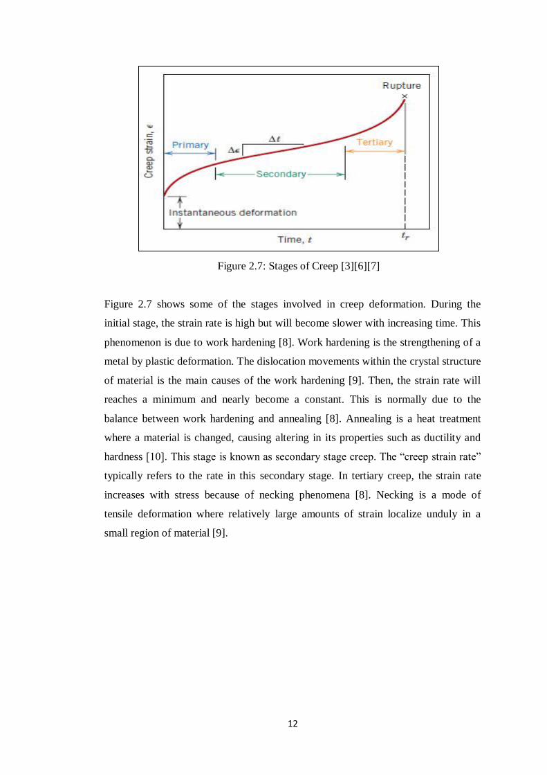
Figure 2.7: Stages of Creep [3][6][7]
Figure 2.7 shows some of the stages involved in creep deformation. During the
initial stage, the strain rate is high but will become slower with increasing time. This
phenomenon is due to work hardening [8]. Work hardening is the strengthening of a
metal by plastic deformation. The dislocation movements within the crystal structure
of material is the main causes of the work hardening [9]. Then, the strain rate will
reaches a minimum and nearly become a constant. This is normally due to the
balance between work hardening and annealing [8]. Annealing is a heat treatment
where a material is changed, causing altering in its properties such as ductility and
hardness [10]. This stage is known as secondary stage creep. The “creep strain rate”
typically refers to the rate in this secondary stage. In tertiary creep, the strain rate
increases with stress because of necking phenomena [8]. Necking is a mode of
tensile deformation where relatively large amounts of strain localize unduly in a
small region of material [9].

13
2.5.1 Remaining Creep Life Prediction Methods
One of the methods used to predict the remaining creep life is the Stress-Rupture
Test (SRT). This method will compute the time to failure of the specimen at certain
stress and temperature. Furthermore, it is known as a sudden and complete failure of
a material held under a definite constant load for a given period of time at a specific
temperature. This test will lead to equations that will be used to obtain the remaining
creep life prediction. One of equations is the Larson-Miller Parameter, which in
generalized form is:
[11]
where, T is the operating temperature (K), tr is the time to rupture (h) and c is the
material specific constant often approximated as 20 for most type of metal [11][12].
The experimental data obtain will be extrapolate using this relation.
Another equation that will be used to predict the remaining creep life is the Life
Fraction Rule proposed by Robinson [11]. The equation is shown below:
[11]
[11]
where, Ts is the actual service life of blades (h), Trs is the operational creep life of
service-exposed blades (h), tr is the rupture time of service-exposed blades under
accelerated test condition (h), tr* is the rupture time of the new materials (unexposed
blades) under the same accelerated test conditions (h) and R.L. is the residual life of
service-exposed blades (h). [11][12]

14
CHAPTER 3
RESEARCH METHODOLOGY
3.1 Project Activities
3.1.1 Cutting of sample for Field Emission Scanning Electron Microscope
(FESEM) experiment
The process was done at Block 16, UTP with the assists from Mr. Zamil (Lab
Technician) using the EDM (Electrical Discharge Machining) Wire Cut Machine.
The desired dimension for the sample is 10 mm (height) x 10 mm (width) x 10 mm
(length).
Figure 3.1: GE Gas Turbine blades
(1st and 3
rd Stage)
Figure 3.2: Machine setting process
Figure 3.3: The cutting process Figure 3.4: The desired sample

15
There were two samples produced which are from the 1st stage and 3
rd stage
respectively for microstructure comparison purpose. The different between those
samples are the 1st stage sample was taken from the tip outer region (overheated)
whereas the 3rd
stage sample was taken from the top inner region (normal condition).
The following are the detailed steps taken to cut the sample [11]:
1. The desired dimension was given to the technician. The technician will enter
the data on the EDM Wire Cut Machine.
2. A flat metal base was glued to the root of the blade. This is done to ensure
that the angle of the blade is 90° to the wire that will cut it.
3. The wire cutting was done based on the dimension desired.
4. The steps were repeated to produce the other sample.

16
3.1.2 Sample Preparation for the Field Emission Scanning Electron Microscope
(FESEM) experiment.
The process was done at Block 17, UTP with the assists from Mr. Mahfuz (Lab
Technician).
Figure 3.5: Mounting Process Figure 3.6: Grinding and
Polishing process
Figure 3.7: Preparation of etching
solution
Figure 3.8: Etching process
Figure 3.9: Etched sample

17
The following are the steps to prepare the sample [10]:
1. The sample was mounted by using the Auto Mounting Press machine. The
purpose of mounting is to provide a comfortable way to hold the sample
while it is being grinded and polished.
2. The sample will be grinded at different grits to achieve a mirror-like image. It
was started by using very fine grits until ultra fine grits (P240-P4000).
3. The sandpaper was replaced with polishing cloth and diamond polishing for
polishing purpose. The purpose of polishing is to remove the damage
introduced by the previous step. Diamond powder is an abrasive material that
use to achieve the fastest material removal.
4. Finally, the etching process was done.
Etching
Material of blade: Inconel 738 [10]
Etching Solution: Ni etchant solution [10]
Materials needed: Nitric acid (HNO3), Acetic acid (CH3COOH), Sulphuric acid
(H2SO4), Distilled water, Glass container [10]
Procedure [10]:
1. 100 ml of distilled water was prepared in the glass container.
2. 50 ml of HNO3 was poured into the glass container followed by 50 ml of
CH3COOH and 20 ml of H2SO4 and it was mixed together.
3. The sample was soaked into the solution with mild agitation.
4. The sample was checked by distilled water rinse every 30 seconds or every
minute until the Nickel colour was gone.
5. The sample was dried after a thorough distilled water rinse.
6. The preliminary observation was done by using the Optical Microscope.

18
3.1.3 Field Emission Scanning Electron Microscope (FESEM) experiment
The process was done at Centralized Analytical Lab (CAL), Block P, UTP with the
assists from Mr. Anuar (Lab Technologist).
Figure 3.10: Field Emission Scanning
Electron Microscope (FESEM)
Figure 3.11: Setting up the FESEM machine
Figure 3.12: Discussion between the
lecturer and Graduate Assistor (GA)

19
3.1.4 Study of sample preparation for Stress-Rupture test
Since the experiment could not be carried out due to High Temperature Creep
Testing Machine (HTCTM) unavailability, the author decided to study the step
required to fabricate the sample for the Stress-Rupture test. The sample dimension
guideline is shown below:
The steps taken to prepare the sample [11]:
1. Glue a flat metal base to the roof of the blade. The purpose of the glue is to
ensure that the angle of the blade is 90° to the wire that will cut it.
2. After the glue has dried, the same metal base will be welded to the root of the
blade. The purpose of welding is to avoid disconnection during vibration of
the EDM Wire Cut Machine.
3. After the weld has cooled off, the wire cutting can be done.
4. The grip holes will be fabricated using the EDM Drilling Machine. An
electrode will be used by the machine to penetrate the surface of the blade.
Marking have to be done properly to avoid error as the machine will operate
manually.
5. The EDM Wire Cut Machine will be used once the holes are big enough for a
wire to go through on the blade surface.
6. The steps were repeated to produce the other sample.
Figure 3.13: Sample dimension guideline

20
3.2 List of Machines and Hardware used
Table 3.1: List of Machines and Hardware used
Machines/Hardware Function
EDM Wire Cut machine Used to cut the turbine blades into desired dimension
FESEM Used to produce microstructure images and chemical
composition of the sample
Auto Mounting Press
machine
Used to mount the sample to provide a better grip on the
sample
Grinding machine Used to produce a mirror-like image
Polishing machine Used to remove the damage introduced by grinding process
Ni etchant solution Used to produce the perfect surface for FESEM
examination

21
3.3 Flow of the Project
Review literatures related to the project title
Develop an extended proposal
Sample preparation
Conduct the experiment
Analyze and interpret the data from the experiment
Provide a report for the research
Presentation of project
Submission of Final Year Project Report
Figure 3.14: Flow of the Project

22
3.4 Experimental Procedures
Figure 3.15: Experimental procedures
Step 1 Prepare the sample
Step 2 Determine the chemical composition and
microstructure of the sample by FESEM experiment
Step 3 Analyze the result data
Step 4 Study the High Temperature Creep Testing
Step 5 Analyze the data
Step 6 Finalize the data obtain

23
3.5 Gantt Chart & Key-Milestones for FYP I
Table 3.2: Gantt Chart & Key-Milestones for FYP I
Legends:
Process
Key Milestones
No.
Details
Weeks
1 2 3 4 5 6 7
MID
SE
ME
ST
ER
BR
EA
K
8 9 10 11 12 13 14
1 Consolidation of FYP Topics
2 Topic assignments to students
3 Research for the topic assigned
3 Preparation for Extended Proposal
4 Submission of Extended Proposal
5 Research for the experimental procedure and work
6 Research for the material properties
7 Preparation for Proposal Defence
8 Proposal Defence
9 Preparation for Interim Report
10 Submission of Interim Report

24
3.6 Gantt Chart & Key-Milestones for FYP II
Table 3.3: Gantt Chart & Key-Milestones for FYP II
Legends:
Process
Key Milestones
No.
Details
Weeks
1 2 3 4 5 6 7
MID
SE
ME
ST
ER
BR
EA
K
8 9 10 11 12 13 14
1 Lab Bookings
2 Appointment with Lab Technician
3 Cutting the Sample
3 Sample Preparation for FESEM experiment
4 FESEM experiment
5 Submission of Progress Report
6 High Temperature Creep Testing Experiment
7 Poster Submission
8 Submission of Dissertation (softbound)
9 Submission of Technical Paper
10 Oral Presentation (Viva)
11 Submission of Dissertation (hardbound)

25
CHAPTER 4
RESULTS & DISCUSSION
Results and discussion can be divided into two parts:-
a. Field Emission Scanning Electron Microscope (FESEM)
i. 1st Stage of used Gas Turbine Blade (Overheated)
ii. 3rd
Stage of used Gas Turbine Blade (Normal Condition)
b. Stress-Rupture test analysis
4.1 Field Emission Scanning Electron Microscope (FESEM)
This experiment was done to investigate the microstructure arrangement and the
chemical composition of the sample at different stage of used gas turbine blade.
a. i. 1st Stage of used Gas Turbine Blade Microstructure
Based on Figure 4.1, it is very clear that the 1st Stage used Gas Turbine blade
(overheated), presented aligned and connected carbides, which formed preferential
sites for nucleation and propagation of cracks [11].
Figure 4.1:1st Stage of used Gas Turbine Blade at 1.0 K X magnification

26
Other than that, another important observation was the heterogeneous distribution of
phase Cobalt (Co) precipitates, whose segregation is harmful to the mechanical
properties of the material. Furthermore, the coarsened gamma (γ) size is in the range
of 0.5–2 µm in this section. The large size coarsened γ precipitates are surrounded
by the γ denuded zone (darker regions), devoid of secondary γ precipitates.
Figures 4.2 show carbides precipitation in grain boundaries that is represented in the
formation of continuous films (including 13.24 percent Cr) and dispersed particles
(include 6.81 percent Ti) of carbides, respectively. Carbides precipitation results in
decreasing of alloy ductility and toughness [11]. Figure 4.2 show a material in the
middle stage of secondary creep. The “creep strain rate” typically refers to the rate in
this secondary stage [8]. Furthermore, there were a large number of cracks at
different regions of blades because of operation at high temperatures and stresses
over a long period of time. Some of these cracks are shown in Figures 4.2. In Figure
4.2, the author observed an intergranular crack on fracture surface. The appearance
of the fracture surface resembles a dimple-like fracture. The dimple-like appearance
can be attributed to the microcavities, which could be related to intergranular
decohesion of carbides [12]. These microcavities serve as the origin of a creep
failure mechanism. Also, the author observed an intergranular crack on the 1st stage
blade coating and several intergranular cracks that were located on transverse section
Figure 4.2:1st Stage of used Gas Turbine Blade at 3.0 K X magnification

27
of the blade surface (Figure 4.2). The coating crack initiation was probably due to a
thermal fatigue mechanism, as a result of high thermal transient loads and crack
grain boundary initiation and propagation in the substrate by a creep mechanism
(high steady state loads) [11][12].
ii. 1st Stage of used Gas Turbine Blade Chemical Composition
Based on Figure 4.3, the major elements in the blades are Nickel, giving an initial
judgment that the blade is made of Nickel-based superalloys. Then, further study was
done; comparing the result obtained from FESEM examination with literatures.
Finally, it has been concluded that the type of alloy used to fabricate the blades is
Inconel 738 [10]. Inconel 738 offers a combination of outstanding high-heat creep
rupture strength and corrosion resistance. It is also better than many high-strength
superalloys with lower chromium content. The nickel-based alloys are vacuum-cast
and precipitation-hardened, offering exceptional mechanical properties. Inconel 738
holds up to the hot corrosive environments found in the gas turbine industry [10].
Figure 4.3:1st Stage of used Gas Turbine blade Chemical Composition

28
Based on Table 4.1, it can be justified that Nickel is the major element inside the 1st
stage used gas turbine blade. The blade was made up of approximately 42.13 %
percent of Nickel. Nickel is a chemical element with the symbol Ni and atomic
number 28. It is a silvery-white lustrous metal with a slight golden tinge. Nickel
belongs to the transition metals and it is hard and ductile [11]. The least element was
Tantalum with 0.95%. Tantalum is also a chemical element with the symbol Ta and
atomic number 73. Tantalum is a hard, blue-gray, lustrous transition metal that is
highly corrosion resistant [11]. Another major element inside the blade is Carbon
(31.01%). These particles are present in these alloys for two main reasons: because it
is very difficult to remove carbon during refining and because carbon is added on
purpose to form carbides, which improve creep properties [12].
Table 4.1: 1st Stage of used Gas Turbine blade
Tabulated Chemical Composition
Element
Weight%
Atomic%
C K 31.01 70.65
Al K 1.10 1.11
Ti K 6.81 3.89
Cr K 13.24 2.00
Co K 4.75 2.21
Ni K 42.13 19.64
Ta M 0.95 0.50
Totals 100.00

29
b. i. 3rd
Stage of used Gas Turbine Blade Microstructure
Based on Figure 4.4, 3rd
stage used Gas Turbine blade (normal condition), it shows a
much less heterogeneous matrix than sample 1, not only in relation to Cobalt (Co)
precipitates, but also carbides, which, in this case, are less dispersed throughout the
gamma (γ) matrix [11]. Co precipitates segregation is harmful to the mechanical
properties of the material. In addition, the carbides precipitation in grain boundaries
that is represented in the formation of continuous films is not that much compared to
the 1st stage blade (including 8.14 percent Cr) and dispersed particles (include 2.47
percent Ti) of carbides, respectively. Carbides precipitation will result to
intergranular corrosion. This situation can happen in corrosion-resistant alloys, when
the grain boundaries are depleted, known as grain boundary depletion, of the
corrosion-inhibiting elements such as Chromium. This mechanism is called
sensitization. Carbides precipitation would also results in decreasing of alloy
ductility and toughness [11].
Figure 4.4:3rd Stage of used Gas Turbine blade at 500 X magnification

30
Based on Figure 4.5, cracks and fracture seems just begin to develop as it cannot be
clearly seen compared to the other sample in Figure 4.2. This shows that the 3rd
stage
blade was not subjected to high stress and temperature experienced by the 1st stage
blade. But still, there were stress and temperature that affect the performance of the
3rd
stage blade. Based on Figure 4.5, it shows that the grain boundaries are begin to
coarse as a result of creep effect in a high stress and temperature inside a gas turbine.
But, it cannot be clearly seen as it is still in the early stage of secondary creep. The
“creep strain rate” typically refers to the rate in this secondary stage [8]. Other than
that, the cracks are begin to develop as a result of centrifugal force inside the turbine.
In addition, it is also affected by the operation at high temperatures and stresses over
a long period of time. The large white portion can be attributed to the microcavities,
which could be related to intergranular decohesion of carbides. These microcavities
serve as the origin of a creep failure mechanism [11][12].
Figure 4.5:3rd Stage of used Gas Turbine blade at 3.00 K X magnification

31
ii. 3rd
Stage of used Gas Turbine Blade Chemical Composition
Based on Figure 4.6, the major elements in the blades are Nickel, which support the
judgment that the blade is made of Nickel-based superalloys. This is supported by
the comparison between the results obtained from FESEM examination with
literatures. It had been conclude that the material used to manufacture the blade is
Inconel 738. Inconel 738 offers a combination of outstanding high-heat creep rupture
strength and corrosion resistance. It is also better than many high-strength super
alloys with lower chromium content. The nickel-based alloys are vacuum-cast and
precipitation-hardened, offering exceptional mechanical properties. Inconel 738
holds up to the hot corrosive environments found in the gas turbine industry [10].
Figure 4.6:3rd Stage of used Gas Turbine blade Chemical Composition

32
Based on Table 4.2, once again that it can be clearly seen that Nickel is the major
element inside the 1st stage used gas turbine blade. The blade consists of
approximately 55.91 % percent of Nickel. The least element was Tantalum with
0.61%. Still the second largest portion is Carbon (18.17%). These particles are
present in these alloys for two main reasons: because it is very difficult to remove
carbon during refining and because carbon is added on purpose to form carbides,
which improve creep properties [12].
Table 4.2: 3rd Stage of used Gas Turbine blade
Tabulated Chemical Composition
Table 4.3 shows the tensile properties of Inconel 738. It shows that the Elastic
Modulus is 110 GPA, Yield Strength is 950 MPa, and Ultimate Tensile Strength is
1100 MPa [13][14].
Table 4.3: Tensile properties of Inconel 738 [13][14]
Element Weight% Atomic%
C K 18.17 29.14
Al K 2.80 4.46
Ta K 0.61 0.82
Ti K 2.47 2.22
Cr K 8.14 15.04
Co K 9.20 6.72
Ni K 55.91 40.97
Totals 100.00
Property
Inconel 738
Elastic Modulus
(GPa)
110
Yield Strength
(MPa)
950
Ultimate Tensile
Strength (MPa)
1100

33
4.2 Stress-Rupture test analysis
Since the High Temperature Creep Testing Machine (HTCTM) is not available,
analysis of journals and literature had been made. An important information that the
author gathered is the blades had been used for 70 000 hours before being sent to
UTP for the remaining creep life prediction purpose. After concluding the type of
material for the blades which is Inconel 738, further research had been done on
previous Stress-Rupture test using Inconel 738 as a sample. Based on the research
obtained, extrapolation of data had been carried out that lead to the following result.
4.2.1 Stress-Rupture test
Stress-Rupture test is widely used in estimation of creep life of high temperature
materials instead of usual creep test because it does not need long periods of time
and it gives a good indication about creep behaviour of materials [12]. The result
obtain in this research is preliminary. A real Stress-Rupture test should be done to
gain a more reliable result. Table 4.4 show the Stress-Rupture test analysis.
Table 4.4: Stress-Rupture test analysis
Actual service
life of blades (h)
Test Condition (MPa) Time to
rupture
(h)
Stress
(MPa)
Temperature (°C)
Unexposed 400 850 602
500 850 311
600 850 98
60 000 400 850 180
500 850 94
600 850 32
70 000 400 850 118
500 850 60
600 850 20
80 000 400 850 53
500 850 27
600 850 10

34
Figure 4.7: Stress-Rupture curve
Based Figure 4.7, it can be clearly seen that the higher the service hour, the shorter
the time taken to rupture. The unexposed blade showed a different pattern of graph
compared to the other service blade. It is less steeper compared to the other that
shows its’ rupture time is very slow.
4.2.2 Remaining Creep Life Prediction
The remaining creep life prediction of blade was done using two different methods:
i. Larson-Miller parameter
ii. Life Fraction Rule
0
100
200
300
400
500
600
700
0 100 200 300 400 500 600 700
Stre
ss (
MP
a)
Time to rupture (hr)
Stress-rupture curve for unexposed and service-exposed blades
Unexposed blade
60000 hr service
70000 hr service
80000 hr service
35
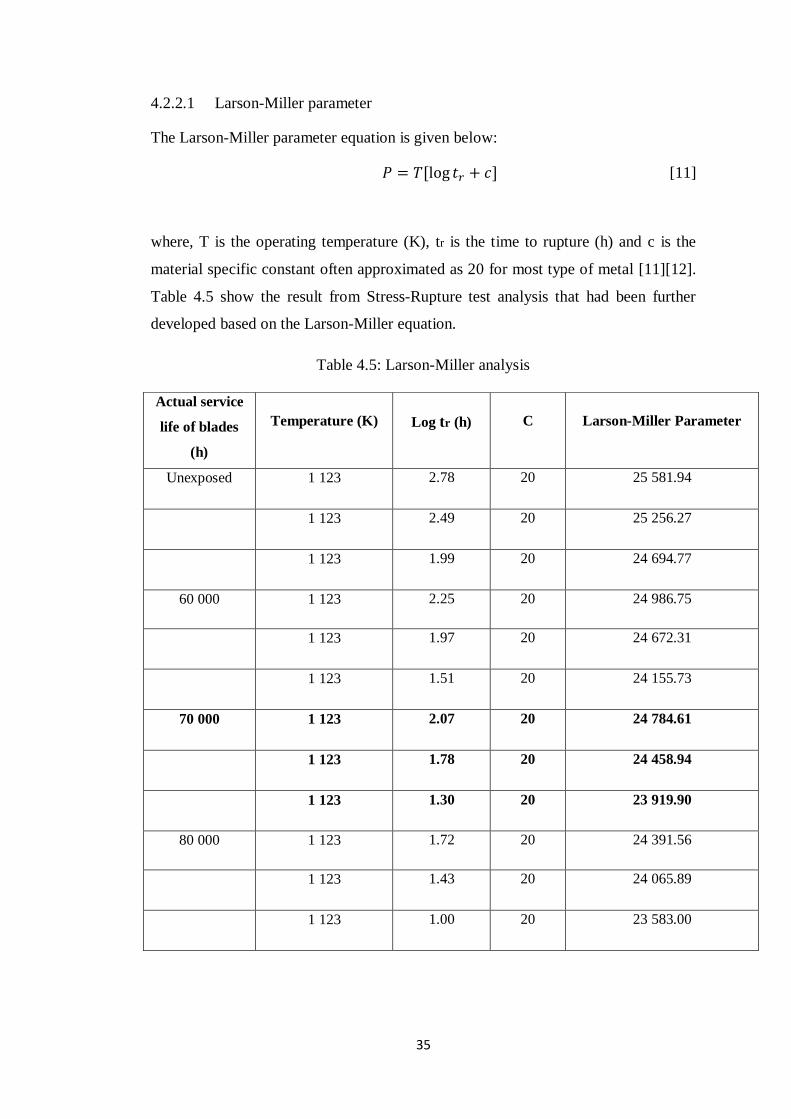
4.2.2.1 Larson-Miller parameter
The Larson-Miller parameter equation is given below:
[11]
where, T is the operating temperature (K), tr is the time to rupture (h) and c is the
material specific constant often approximated as 20 for most type of metal [11][12].
Table 4.5 show the result from Stress-Rupture test analysis that had been further
developed based on the Larson-Miller equation.
Table 4.5: Larson-Miller analysis
Actual service
life of blades
(h)
Temperature (K)
Log tr (h)
C
Larson-Miller Parameter
Unexposed 1 123 2.78 20 25 581.94
1 123 2.49 20 25 256.27
1 123 1.99 20 24 694.77
60 000 1 123 2.25 20 24 986.75
1 123 1.97 20 24 672.31
1 123 1.51 20 24 155.73
70 000 1 123 2.07 20 24 784.61
1 123 1.78 20 24 458.94
1 123 1.30 20 23 919.90
80 000 1 123 1.72 20 24 391.56
1 123 1.43 20 24 065.89
1 123 1.00 20 23 583.00

36
Based on the Figure 4.8, it can be seen that Larson-Miller parameter is increasing as
service hour is decreasing. Usually, the manufacturer will mention the Larson-Miller
parameter value for the blades that they supplied to make its’ easier to predict the
remaining life of the blades. But unfortunately, not all the information is correct. So,
the data obtain from the Stress-Rupture test is more reliable to predict the remaining
creep life of the blades. For an example, the LMP value at stress equals to 550 MPa
for 60 000 hour service blades is 24 829.53. By taking temperature (T) to be equal to
850°C as a constant value throughout the study, we can calculate the data to obtain
the time to rupture. The result will yield approximately 128 hours. This value will be
further used in life fraction rule to obtain the remaining creep life prediction of the
blade.
Figure 4.8: Larson-Miller parameter for unexposed and exposed blades

37
4.2.2.2 Life Fraction rule
The Life Fraction rule equation is given below:
[11]
[11]
where, Ts is the actual service life of blades (h), Trs is the operational creep life of
service-exposed blades (h), tr is the rupture time of service-exposed blades under
accelerated test condition (h), tr* is the rupture time of the new materials (unexposed
blades) under the same accelerated test conditions (h) and R.L. is the residual life of
service-exposed blades (h) [11][12]. The result from the Stress-Rupture test analysis
had been further developed based on the Life Fraction rule equation. This is shown
in Table 4.6.
Table 4.6: Life Fraction rule analysis
Actual service life
of blades (h)
Test Condition (MPa)
Operational
creep life (h)
Residual life
(h)
Stress
(MPa)
Temperature
(°C)
60 000 400 850 86205 26 205
500 850 85206 25 206
600 850 86470 26 470
70 000 400 850 87066 17 066
500 850 86733 16 733
600 850 87949 17 949
80 000 400 850 87723 7 723
500 850 87605 7 605
600 850 89090 9 090

38
Figure 4.9: Relationship between actual service life and residual life of service-
exposed blades
Based on Figure 4.9, it can be clearly seen that the blade from MLNG, Labuan still
can used for more than a year based on its operating stress (MPa) while the
temperature is kept constant. Changing the blade while it still can be use would be a
waste of capital cost on new blade replacement. So, it is very important to do a
proper study on the remaining creep life prediction of used gas turbine blades.
Furthermore, the graph plotted shows that as the operating stress and actual service
life of blades increase, the residual life of blades will decrease. The main causes of
this condition is that the microstructure changes that could not withstand the high
stress and temperature condition inside the gas turbine. This will lead to slow
deformation which is known as creep. Creep is the tendency of a material to change
slowly or deform permanently under the effect of stresses. It is usually affected by a
long term exposure to high levels of stress that are below the Yield Strength of a
certain material such as gas turbine blades [3][6][8]. The Yield Strength of Inconel
738 is 950 MPa. After all, the result obtained in this project is preliminary thus
Stress-Rupture tests have to be carried out to improve the outcome.
0
5000
10000
15000
20000
25000
30000
55000 65000 75000 85000
Re
sid
ual
Lif
e o
f B
lad
es
(hr)
Actual Service Life of Blades (hr)
Actual Service Life of Blades (hr) vs Residual Life of Blades (hr)
at 400 MPa
at 500 MPa
at 600 MPa

39
CHAPTER 5
CONCLUSION AND RECOMMENDATIONS
5.1 Conclusion
In conclusion, the author managed to achieve the objective of the study. The main
objective of the study was to predict the remaining creep life of used gas turbine
blades. As we all known, turbine blades is expensive and costly material. In order to
save capital cost, it is very important to know when will the blade reach its’ deform
state without believing 100% to the information given by the manufacturer. This will
also ensure that the blade will not be change earlier or too late. By conducting the
research, the author managed to have a preliminary result on remaining creep life
prediction of the used gas turbine blade supplied by MLNG, Labuan. With the
application of Larson-Miller parameter and Life Fraction rule, the author had found
out that the supplied blade still can be used for more than a year based on its’
operating stress and temperature inside the gas turbine. Besides that, two different
sample which are 1st stage used gas turbine blade (overheated) and 3
rd stage used gas
turbine blade (normal operation) were compared based on metallurgical analysis. It
had been found out that the 1st stage used gas turbine blade (overheated) suffer more
compared to the 3rd
stage used gas turbine blade (normal operation) from several
microstructure changes, which affect their function. They are formation of cracks,
fractures and coarsening of grain boundaries on the material as a result from high
stress and temperature condition. Lastly, the author hopes that the Stress-Rupture test
can be carried out by using the High Temperature Creep Testing Machine (HTCTM)
in the future to obtain a more reliable result.

40
5.2 Recommendations
If the experiment can be conducted in the future, it is very important to examine the
microstructure after the Stress-Rupture test had been carried out. This will draw a
comparison between the microstructure before and after the blade has rupture.
Furthermore, the chemical composition could also be compared. This will lead to a
more precise result. Besides that, Stress-Rupture test will take a lot of time. It might
take a month or more to obtain the result since the samples need to reach its rupture
time under different operating stress. In addition, sample preparation for both
microstructure and Stress-Rupture test will take some time. So, the best thing is to
start earlier and have a fix guideline that must be obeyed to avoid any delay. Since
the High Temperature Creep Testing Machine (HTCTM) is not available in UTP, it
is very important to contact the person who can help to perform Stress-Rupture test
as earlier as possible. Reservation should be made earlier to avoid complication in
the future. Besides that, always keep in touch with respective supervisor. The author
hope that the preliminary result could be modify in the future after the Stress-
Rupture test had been perform.

41
CHAPTER 6
REFERENCES
[1] H.I.H. Saravanamuttoo, G.F.C. Rogers and H. Cohen, 2001, Gas Turbine
(5th ed.) Theory Pearson Education.
[2] Boyce, Meherwan P., 2006, Chapter 9: Axial Flow Turbines, Chapter 11:
Materials, Gas Turbine Engineering Handbook (3rd ed.), Oxford, Elsevier.
[3] Frost, Harold J.,Ashby, Michael F,1982, Deformation-Mechanism Maps: The
Plasticity and Creep of Metals and Ceramics, Pergamon Press.
[4] John Molloy,1998, Forensic Investigation of a Gas Turbine Event, M&M
Engineering.
[5] Schilke, P. W., 2004, Advanced Gas Turbine Materials and Coatings. GE
Energy.
[6] Ashby, Michael F.,Jones, David R. H., 1980, Engineering Materials 1: An
Introduction to their Properties and Applications, Pergamon Press.
[7] Beer, Ferdinand P., Johnston, E. Russell, Dewolf, John T., 2001, Mechanics
of Materials (3rd ed.). McGraw-Hill.
[8] Smith, William F., Hashemi, Javad, 2006, Foundations of Materials Science
and Engineering (4th ed.), McGraw-Hill.
[9] Degarmo, E. Paul, Black, J T., Kohser, Ronald A., 2003, Materials and
Processes in Manufacturing (9th ed.), Wiley.
[10] Van Vlack, L.H., 1985, Elements of Materials Science and Engineering,
Addison-Wesley.

42
[11] Walls, D.P., Delaneuville, R.E., and Cunningham, S.E., 1997, Damage
Tolerance Based Life Prediction in Gas Turbine Engine under Vibratory
High Cycle Fatigue, Journal of Engineering for Gas Turbines and Power, vol.
119, 1997, pp. 143–6.
[12] Burns, J., 1998, Gas Turbine Engine Blade Life Prediction for High Cycle
Fatigue,The Technical Cooperation Program (TTCP), P-TP1.
[13] Hertzberg, Richard W., 1996 Deformation and Fracture Mechanics of
Engineering Materials, Fourth Edition. John Wiley and Sons, Inc., Hoboken,
NJ.
[14] Larson, F.R.; and Miller, James: A Time-Temperature Relationship for
Rupture and Creep Stresses. Trans. ASME, vol. 74, pp. 765−775.
[15] B. Walser, September 1979, Proceedings of Conference on Heat and Mass
Transfer in Metallurgical System, Yugoslavia, p. 673.
[16] C. Barbosa, J.L. Nascimento, I.M.V. Caminha, I.C. Abud, Sepetember 2003
Acta Macroscopica.
[17] Y. Xu, J.L. Bassani,1999, Mater. Sci. Eng. A260.
[18] R. Castillo, A.K. Koul, E.H Toscano, 1987, J. Eng. Gas Turbines Power.
[19] R. Castillo, A.K. Koul, 1986, Proceedings of Conference on High Temp.
Alloys for Gas Turbine & Other Applications, Belgium.
[20] M.A Meyers, K.K. Chawla, 1999, Mechanical Behaviours of Materials,
Prentice-Hall International Inc.

43
CHAPTER 7
APPENDICES
7.1 Field Emission Scanning Electron Microscope (FESEM)
Figure 7.1: 1st Stage of used Gas Turbine blade Electron Image
Figure 7.2: 3rd
Stage of used Gas Turbine blade Electron Image

44
7.2 High Temperature Creep Testing Machine (HTCTM)
Figure 7.3: High Temperature Creep Testing Machine (HTCTM) [12]

45
7.3 Creep Life Prediction Method
For 70 000 hours service blade, Stress (σ) applied = 600 MPa
7.3.1 Larson-Miller Parameter
Given,
T = 850 °C
= 850 + 273
= 1123 K
= 20 h
C = 20
P = 1123 (log 20 + 20)
P = 23 919.90
7.3.2 Life Fraction Rule
Given,
Ts = 70 000 h
Trs = ?
tr = 20
tr* = 98
= 1 – 0.204
Trs = 87 949
R.L = 87 949 – 70 000
R.L = 17 949 hours