chapter 1 introductionto power quality...
TRANSCRIPT
Chapter 1
Introduction to Power Quality
Issues and Solutions with Emphasis
on Shunt Active Power Filters
1.1 Introduction
In last few decades industrial growth throughout the globe has been tremendous. Au-
tomation at various levels is one of the prime factors for this growth. Advancement
in power semiconductor device technology, availability of fast & efficient power elec-
tronic devices (static/semiconductor switches) at higher power rating, and advent of
fast digital signal processors (DSPs) have made it possible to implement control and
automation for sustained industrial growth. Power electronic devices based converters
have found numerous applications like, induction furnace, arc furnace, welding, light-
ing (electronic ballasts for tubular fluorescent lamps, compact fluorescent lamps and
light emitting diode lights), power supplies (uninterruptible power supplies [UPS],
switched mode power supplies [SMPS]), hybrid electric vehicles (HEV), high volt-
age dc (HVDC) transmission systems, flexible ac transmission (FACT) devices, vari-
able frequency drives (VFDs) for motor control, cycloconverters, uncontrolled (diode
based) and controlled (thyristor based) rectifiers (front-end converters), pulse width
modulation (PWM) inverters, choppers, etc., are a few to name. Most of these power
electronic converters are considered as non-linear loads that inject current harmonics
in the power system.
Widespread interaction of these non-linear loads with utility draws non-sinusoidal cur-
rents from ac mains producing a considerable amount of harmonic current. Following
are the problems created by harmonics currents [1]:
• Excessive heating and failure of capacitors, capacitor fuses, transformers, mo-
1
Chapter 1 Introduction to Power Quality Issues and Solutions with Emphasis on SAPF 2
tors, fluorescent lighting ballasts, etc.
• Nuisance tripping of circuit breaker or blown fuses
• Presence of the third-harmonic and multiples of it in neutral grounding systems
may require the derating of neutral conductors
• Noise from harmonics that lead to erroneous operation of control system com-
ponents
• Damage to sensitive electronic equipment
• Electronic communications interference
• More severely, line voltage distortion (depending on the short-circuit ratio of
the system and the harmonic constant of the converter used).
1.2 Power quality
In recent years, the issue of power quality has gained increased interest of researchers
because of more and more usage of power quality sensitive loads. At the same time,
improvement in power quality has become more challenging task as the loads them-
selves (mostly non-linear loads) become important causes of the degradation of power
quality. For utilities, providing adequate power quality has been a prime focus be-
cause of changes in consumer (mainly industrial) equipment and requirements. For
the user, problems of new equipment sensitivity to service quality have come as un-
expected surprises. Many electronic devices, such as computers, process controls,
medical equipment, communication equipment and power supplies, are sensitive to
power system disturbances. Several authors have attempted to define the term ‘power
quality’ in literature [2]-[3], however there is a lack of universally accepted definition.
For example, International Electrotechnical Commission (IEC) defines power quality
as a set of parameters defining the properties of the power supply as delivered to the
user in normal operating conditions in terms of continuity of supply and characteristics
of voltage (symmetry, frequency, magnitude, and waveform) [2]. Further, Institute
of Electrical and Electronics Engineers (IEEE) standard 1100-2005 [3] defines power
quality as the concept of powering and grounding electronic equipment in a manner
that is suitable to the operation of that equipment and compatible with the premise
wiring system and other connected equipment. In a broader perspective, power qual-
ity includes considerations regarding different aspects of reliability of electrical power
supply such as distortion, phase unbalance, line interruptions, amplitude variations,
frequency changes, flicker, and transients, etc. But while narrowing down, the focus

Chapter 1 Introduction to Power Quality Issues and Solutions with Emphasis on SAPF 3
of power quality revolves around distortion in waveforms of voltage (at system level)
and current (at equipment level). Due to the extensive use of power converters and
other non-linear loads in industry and by consumers in general, an increasing deteri-
oration of the power systems voltage and current waveforms is observed. The causes
of power quality problems can be categorized as:
• Disturbances arising in the power system (for instance disturbances involving
power lines, and switching to clear faults, lightning strikes, vehicle hit the poles,
etc.)
• Disturbances induced by the operation of customer equipment (for example,
starting of heavy loads, switched mode power supplies, arc furnaces, etc.)
1.3 Mitigation of power quality problems
It is difficult for electric utilities to always ensure a perfect quality of power supply
because some causes of power quality problems are beyond the control of utilities.
For instance, the operation of customer equipment (e.g., power electronic converters)
can cause power disturbances. Thus users of utility power should also play an active
role in the mitigation of power quality problems, especially at equipment level. The
same philosophy is also conveyed by IEEE in its standard 519-1992 [1] that the
utility should be responsible for maintaining quality of voltage waveform, and side-
by-side, consumer should be responsible for limiting harmonic currents injected onto
the power system. Hence, it becomes very essential for the researchers to work for
the improvement of power quality at system level as well as at equipment level. The
quality of power can be improved in two basic ways: [4]
• Circuit arrangement.
• Utilization of power quality improvement equipment.
1.3.1 Circuit arrangement
Quality of power can be improved by electric circuit configuration in following ways:
• Sensitive electronic equipments can be protected from distorted waveforms by
supplying them from dedicated line through separate transformer from feeder
that feeds other loads.
• Making provision of a separate regulating transformer for each sensitive load.
Chapter 1 Introduction to Power Quality Issues and Solutions with Emphasis on SAPF 4
1.3.2 Utilization of power quality improvement equipment
Different types of equipment are available for improving the power quality varying
from cheaper (providing less protection or compensation) to expensive devices (higher
grade of protection or compensation) as per the requirement of power quality improve-
ment. For example, transient voltage surge suppressors are used to detect surges and
reduce them to a safe level while voltage regulators maintain voltage output within
given limits, despite fluctuations in the input. An isolation transformer used for
changing the voltage level can be helpful in compensating for required high or low
voltage.
Devices like passive filters are used to remove harmonics. Active power filters are
used to eliminate harmonics. In broader sense active power filters have wider scope
and serve as active power line conditioners are used to compensate for reactive power,
harmonics and flicker [5]-[16]. An uninterruptible power supply (UPS) along with en-
suring continuity of power supply in case of outages also provides protection against
disturbances like harmonics and electrical noise. Also, different types of flexible ac
transmission devices (FACTS) are used to enhance power quality, mostly at system
level.
Power quality improvement is responsibility not only of the utility supplying power,
but is equal responsibility of the consumers as well. Utilities ensure appropriate qual-
ity of power by installing power quality improvement devices like FACTS at trans-
mission and distribution level, while consumers enhance power quality by installing
capacitor banks, passive filters or Active Power Filters (APFs) at load side. The
research work documented in the thesis is focused on power quality improvement at
load side by installing Shunt Active Power Filter (SAPF).
1.4 Power quality improvement devices - passive
filters
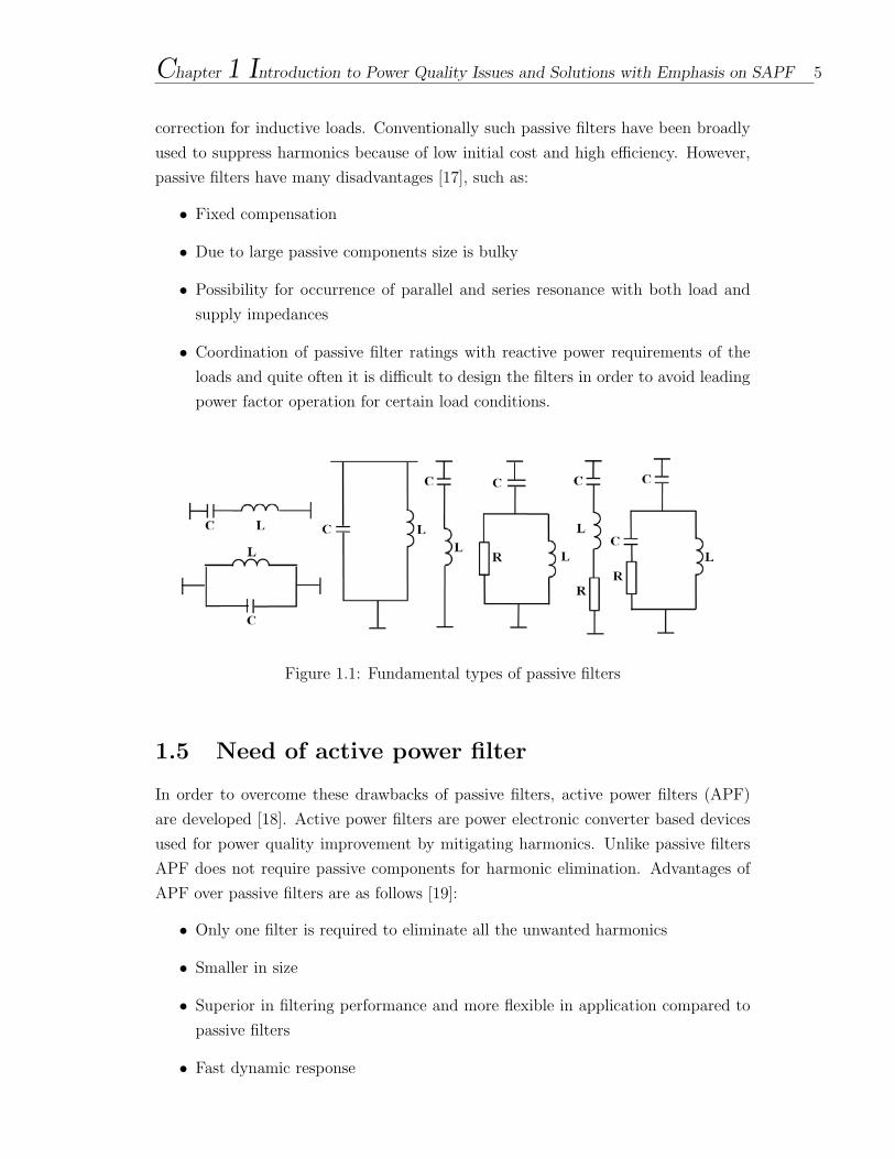
Passive harmonic filters consisting of passive components capacitors, inductors, and/or
resistors are connected in parallel with non-linear loads. Figure 1.1 shows different
configurations of series and shunt type passive filters. Series passive harmonic filters
block the flow of harmonic currents by providing a high harmonic series impedance.
Shunt passive filters installed in the vicinity of a non-linear load provide low-impedance
paths for specific harmonic frequencies. Hence they absorb the dominant harmonic
currents injected by the load. Further passive harmonic filters help in power-factor
Chapter 1 Introduction to Power Quality Issues and Solutions with Emphasis on SAPF 5
correction for inductive loads. Conventionally such passive filters have been broadly
used to suppress harmonics because of low initial cost and high efficiency. However,
passive filters have many disadvantages [17], such as:
• Fixed compensation
• Due to large passive components size is bulky
• Possibility for occurrence of parallel and series resonance with both load and
supply impedances
• Coordination of passive filter ratings with reactive power requirements of the
loads and quite often it is difficult to design the filters in order to avoid leading
power factor operation for certain load conditions.
Figure 1.1: Fundamental types of passive filters
1.5 Need of active power filter
In order to overcome these drawbacks of passive filters, active power filters (APF)
are developed [18]. Active power filters are power electronic converter based devices
used for power quality improvement by mitigating harmonics. Unlike passive filters
APF does not require passive components for harmonic elimination. Advantages of
APF over passive filters are as follows [19]:
• Only one filter is required to eliminate all the unwanted harmonics
• Smaller in size
• Superior in filtering performance and more flexible in application compared to
passive filters
• Fast dynamic response
Chapter 1 Introduction to Power Quality Issues and Solutions with Emphasis on SAPF 6
• Active filters are being able to compensate for harmonics without reactive power
concerns.
Thus active power filter is a better solution as compared to passive filters for elimi-
nation of harmonics and hence improving the power quality.
1.6 Different types of active power filter
Active power filters are power electronic converter based devices that are used for
power quality improvement. Active power filters are basically of three types: - shunt,
series and hybrid APF.
1.6.1 Shunt active power filter
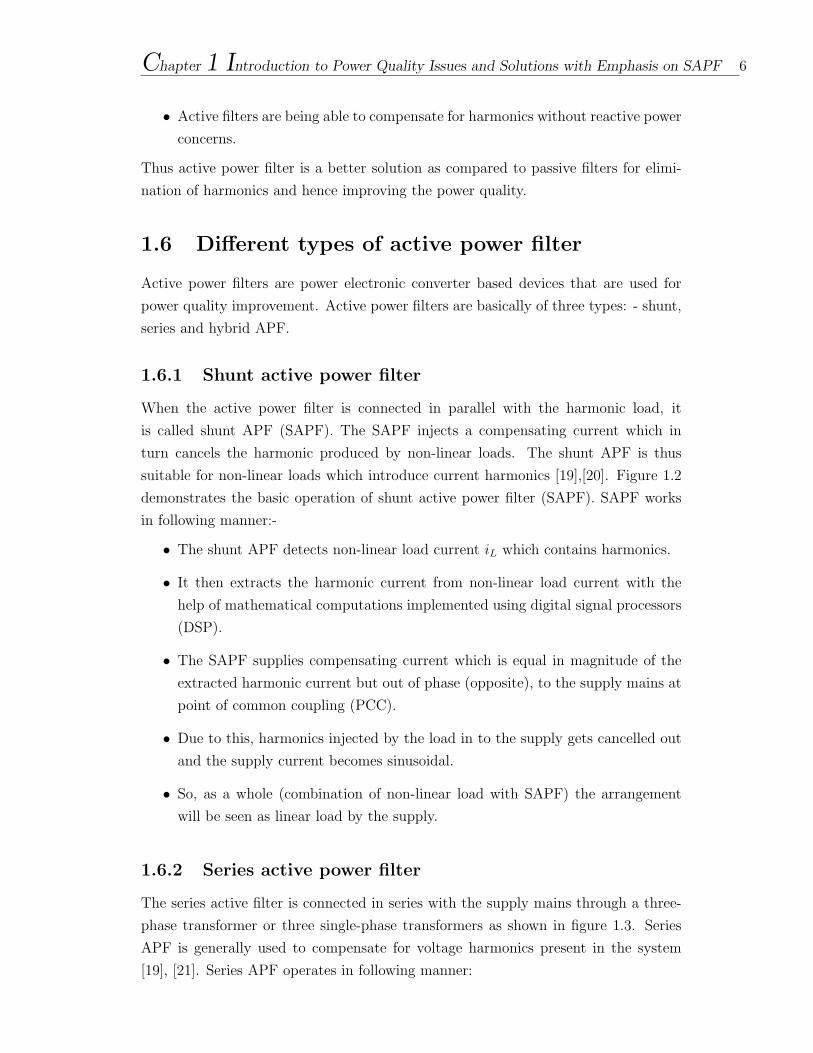
When the active power filter is connected in parallel with the harmonic load, it
is called shunt APF (SAPF). The SAPF injects a compensating current which in
turn cancels the harmonic produced by non-linear loads. The shunt APF is thus
suitable for non-linear loads which introduce current harmonics [19],[20]. Figure 1.2
demonstrates the basic operation of shunt active power filter (SAPF). SAPF works
in following manner:-
• The shunt APF detects non-linear load current iL which contains harmonics.
• It then extracts the harmonic current from non-linear load current with the
help of mathematical computations implemented using digital signal processors
(DSP).
• The SAPF supplies compensating current which is equal in magnitude of the
extracted harmonic current but out of phase (opposite), to the supply mains at
point of common coupling (PCC).
• Due to this, harmonics injected by the load in to the supply gets cancelled out
and the supply current becomes sinusoidal.
• So, as a whole (combination of non-linear load with SAPF) the arrangement
will be seen as linear load by the supply.
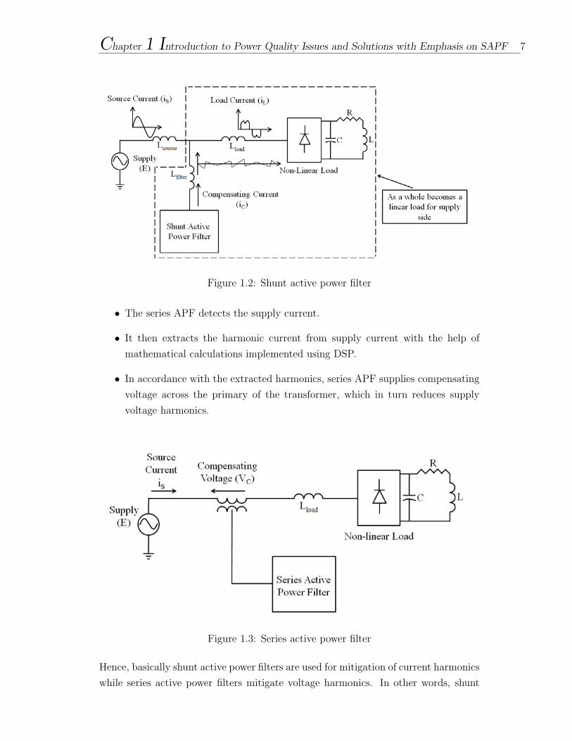
1.6.2 Series active power filter
The series active filter is connected in series with the supply mains through a three-
phase transformer or three single-phase transformers as shown in figure 1.3. Series
APF is generally used to compensate for voltage harmonics present in the system
[19], [21]. Series APF operates in following manner:
Chapter 1 Introduction to Power Quality Issues and Solutions with Emphasis on SAPF 7
Figure 1.2: Shunt active power filter
• The series APF detects the supply current.
• It then extracts the harmonic current from supply current with the help of
mathematical calculations implemented using DSP.
• In accordance with the extracted harmonics, series APF supplies compensating
voltage across the primary of the transformer, which in turn reduces supply
voltage harmonics.
Figure 1.3: Series active power filter
Hence, basically shunt active power filters are used for mitigation of current harmonics
while series active power filters mitigate voltage harmonics. In other words, shunt
Chapter 1 Introduction to Power Quality Issues and Solutions with Emphasis on SAPF 8
active power filter is employed for current stiff circuits whereas the series active power
filter is employed for voltage stiff circuits.
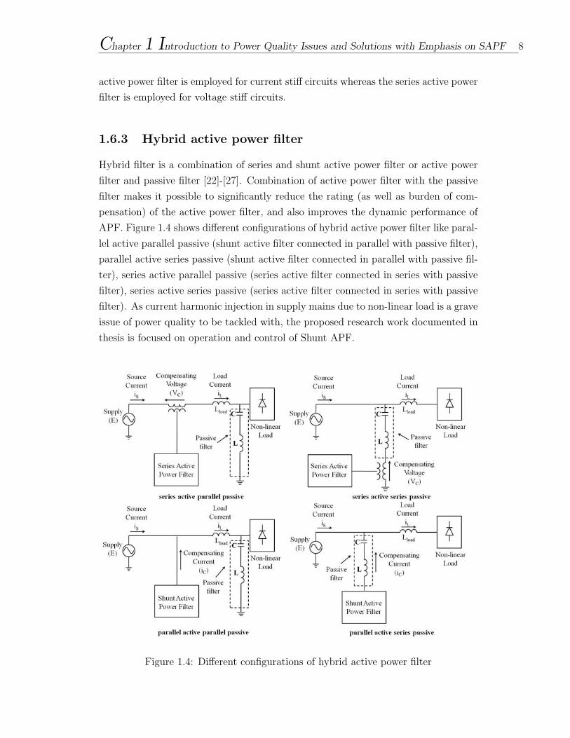
1.6.3 Hybrid active power filter
Hybrid filter is a combination of series and shunt active power filter or active power
filter and passive filter [22]-[27]. Combination of active power filter with the passive
filter makes it possible to significantly reduce the rating (as well as burden of com-
pensation) of the active power filter, and also improves the dynamic performance of
APF. Figure 1.4 shows different configurations of hybrid active power filter like paral-
lel active parallel passive (shunt active filter connected in parallel with passive filter),
parallel active series passive (shunt active filter connected in parallel with passive fil-
ter), series active parallel passive (series active filter connected in series with passive
filter), series active series passive (series active filter connected in series with passive
filter). As current harmonic injection in supply mains due to non-linear load is a grave
issue of power quality to be tackled with, the proposed research work documented in
thesis is focused on operation and control of Shunt APF.
Figure 1.4: Different configurations of hybrid active power filter
Chapter 1 Introduction to Power Quality Issues and Solutions with Emphasis on SAPF 9
1.7 Control of shunt active power filters
As explained above, shunt APF extracts harmonics injected due to non-linear loads by
mathematical computations. These computations are reference compensating current
generation methods. Reference compensating current generation schemes are used to
generate reference compensating currents which will be used as reference to remove the
harmonics from the distorted supply current. Following methods are conventionally
used for reference current generation [28]-[39]:
• Instantaneous reactive power theory
• Synchronous reference frame
• Dc-link voltage control
• Notch filter
• Sliding mode control
• Predictive scheme
• State feedback scheme
• Fast fourier transform method
Detail description of the reference compensating current generation schemes is pre-
sented in Chapter - 3 of this thesis. These reference compensating currents generated
are provided to current controller. Main function of the current controller is to en-
sure that compensating current supplied by APF at PCC remains in line with the
reference compensating current generated by mathematical computations. Hence,
current controller ensures that APF compensating current tracks the reference com-
pensating current. Various types of current controllers are used in APFs, among
which hysteresis controllers are extensively used due to their inherent simplicity in
implementation and fast dynamic response. However, conventional hysteresis current
controller scheme used in APFs suffer from draw backs like limit cycle oscillations,
overshoot in current error, random selection of voltage vectors (not-adjacent) and
generation of sub-harmonic components in current. This is because of no communi-
cation between hysteresis controllers of individual phases. Research work has been
carried out and reported in literature to reduce these problems for their applications
in induction motor drives. [40]-[45].
Current error (generated due to the difference between APF compensating current
and reference compensating current) movement if restricted within a specified bound-
ary will help in compensating for harmonics. Application of current error space vector
Chapter 1 Introduction to Power Quality Issues and Solutions with Emphasis on SAPF 10
based hysteresis controller for control of induction motor drives is studied and doc-
umented in literature [40]-[55]. Researchers have worked upon application of space
vector modulation based hysteresis current controllers for control of SAPF [56]-[59].In
the proposed research work application of current error space phasor based hysteresis
controller to Shunt APF is investigated for power quality improvement.
1.8 Voltage space phasor structure for two-level
inverter
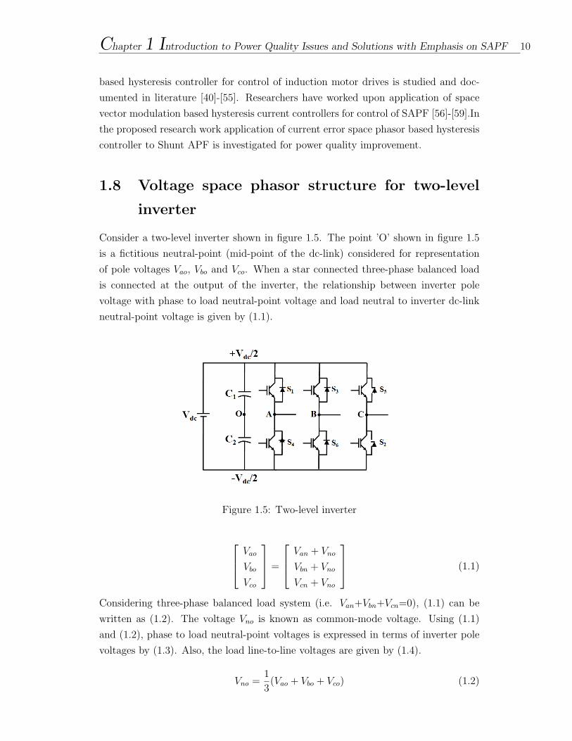
Consider a two-level inverter shown in figure 1.5. The point ’O’ shown in figure 1.5
is a fictitious neutral-point (mid-point of the dc-link) considered for representation
of pole voltages Vao, Vbo and Vco. When a star connected three-phase balanced load
is connected at the output of the inverter, the relationship between inverter pole
voltage with phase to load neutral-point voltage and load neutral to inverter dc-link
neutral-point voltage is given by (1.1).
Figure 1.5: Two-level inverter
Vao
Vbo
Vco
=
Van + Vno
Vbn + Vno
Vcn + Vno
(1.1)
Considering three-phase balanced load system (i.e. Van+Vbn+Vcn=0), (1.1) can be
written as (1.2). The voltage Vno is known as common-mode voltage. Using (1.1)
and (1.2), phase to load neutral-point voltages is expressed in terms of inverter pole
voltages by (1.3). Also, the load line-to-line voltages are given by (1.4).
Vno =1
3(Vao + Vbo + Vco) (1.2)
Chapter 1 Introduction to Power Quality Issues and Solutions with Emphasis on SAPF 11
Van
Vbn
Vcn
=
1
3
2 −1 −1
−1 2 −1
−1 −1 2
Vao
Vbo
Vco
(1.3)
Vab
Vbc
Vca
=
1 −1 0
0 1 −1
−1 0 1
Vao
Vbo
Vco
(1.4)
The inverter voltage space phasor Vs is represented in terms of three pole voltages as
given by (1.5). It is known from (1.1) and (1.2) that the phase voltages Van, Vbn, Vcn
also result in the same voltage space phasor. Thus, the inverter voltage space phasor is
a combination of all the three phase voltages.The space phasor voltage is resolved into
rectangular components along α and β as shown in (1.6). The relationship between
the components of Vs and instantaneous phase voltages of inverter output (derived
by conventional abc-α β transformation)is shown in (1.7).
Vs = Vao + aVbo + a2Vco (1.5)
Where, a=ej2π3
Vs = Vs(α) + jVs(β) (1.6)
[Vs(α)
Vs(β)
]=
[1 −1/2 −1/2
0√3/2 −√
3/2
]
Van
Vbn
Vcn
(1.7)
Van
Vbn
Vcn
=
2/3 0
−1/3 1/√3
−1/3 −1/√3
[Vs(α)
Vs(β)
](1.8)
As shown in figure 1.5, each pole of two-level inverter can attain two voltage levels
Vdc/2 and -Vdc/2. Thus total number of switching states a two-level inverter can
generate is 23=8. For each pole of the two-level inverter, the voltage level Vdc/2
(top device of the pole is ON) is indicated as ’+’, while voltage level -Vdc/2 (lower
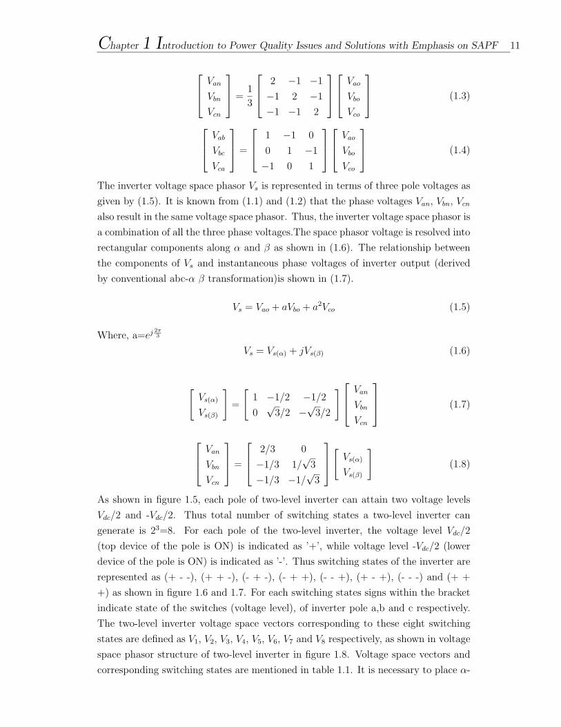
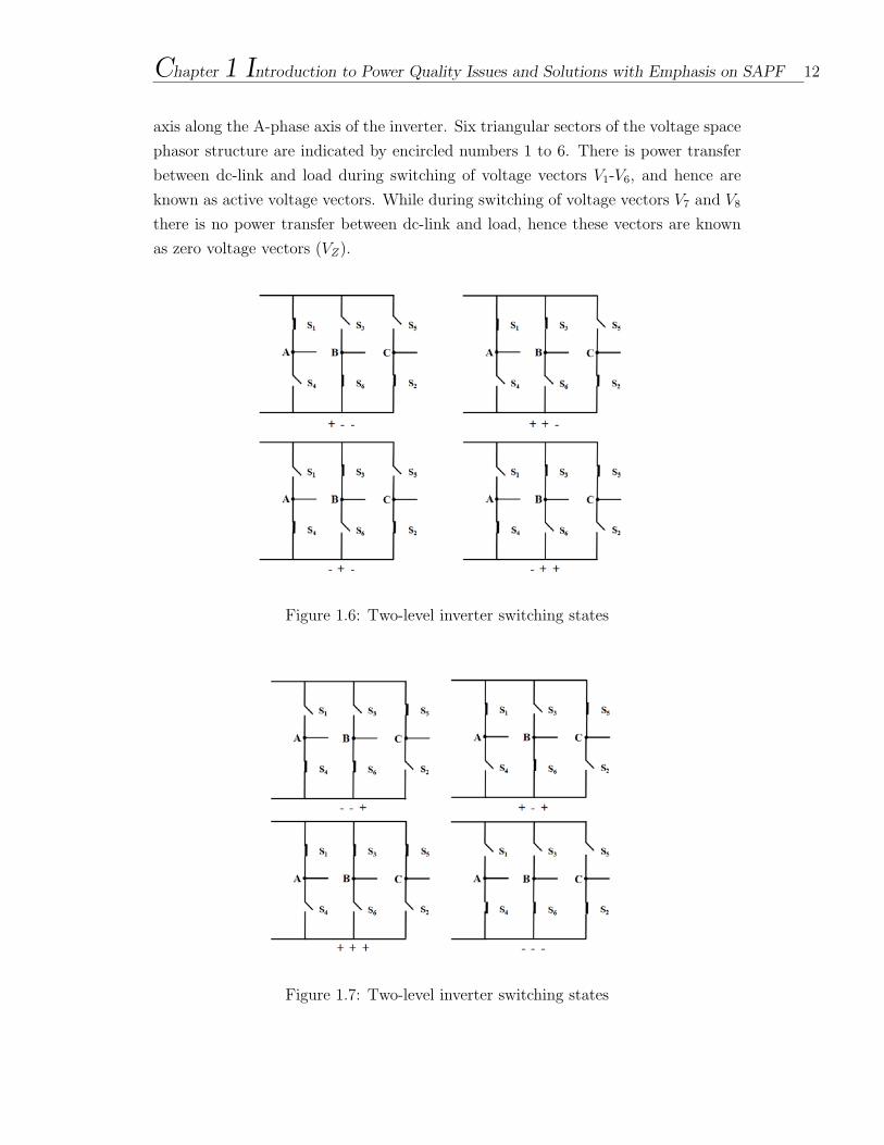
device of the pole is ON) is indicated as ’-’. Thus switching states of the inverter are
represented as (+ - -), (+ + -), (- + -), (- + +), (- - +), (+ - +), (- - -) and (+ +
+) as shown in figure 1.6 and 1.7. For each switching states signs within the bracket
indicate state of the switches (voltage level), of inverter pole a,b and c respectively.
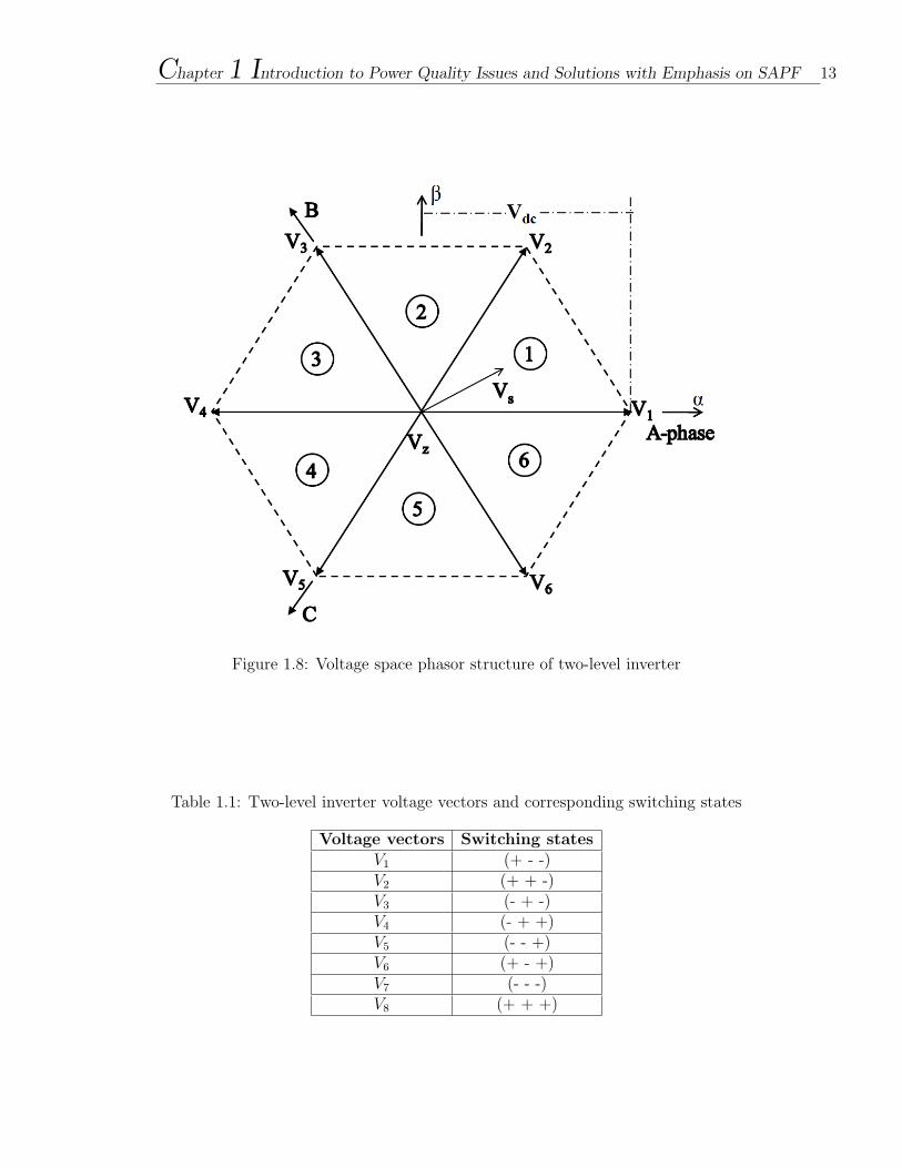
The two-level inverter voltage space vectors corresponding to these eight switching
states are defined as V1, V2, V3, V4, V5, V6, V7 and V8 respectively, as shown in voltage
space phasor structure of two-level inverter in figure 1.8. Voltage space vectors and
corresponding switching states are mentioned in table 1.1. It is necessary to place α-
Chapter 1 Introduction to Power Quality Issues and Solutions with Emphasis on SAPF 12
axis along the A-phase axis of the inverter. Six triangular sectors of the voltage space
phasor structure are indicated by encircled numbers 1 to 6. There is power transfer
between dc-link and load during switching of voltage vectors V1-V6, and hence are
known as active voltage vectors. While during switching of voltage vectors V7 and V8
there is no power transfer between dc-link and load, hence these vectors are known
as zero voltage vectors (VZ).
Figure 1.6: Two-level inverter switching states
Figure 1.7: Two-level inverter switching states
Chapter 1 Introduction to Power Quality Issues and Solutions with Emphasis on SAPF 13
Figure 1.8: Voltage space phasor structure of two-level inverter
Table 1.1: Two-level inverter voltage vectors and corresponding switching states
Voltage vectors Switching statesV1 (+ - -)V2 (+ + -)V3 (- + -)V4 (- + +)V5 (- - +)V6 (+ - +)V7 (- - -)V8 (+ + +)
Chapter 1 Introduction to Power Quality Issues and Solutions with Emphasis on SAPF 14
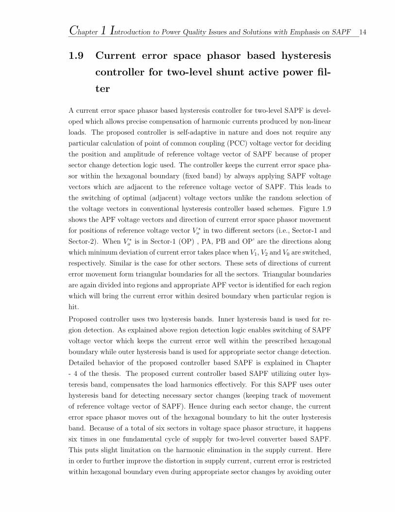
1.9 Current error space phasor based hysteresis
controller for two-level shunt active power fil-
ter
A current error space phasor based hysteresis controller for two-level SAPF is devel-
oped which allows precise compensation of harmonic currents produced by non-linear
loads. The proposed controller is self-adaptive in nature and does not require any
particular calculation of point of common coupling (PCC) voltage vector for deciding
the position and amplitude of reference voltage vector of SAPF because of proper
sector change detection logic used. The controller keeps the current error space pha-
sor within the hexagonal boundary (fixed band) by always applying SAPF voltage
vectors which are adjacent to the reference voltage vector of SAPF. This leads to
the switching of optimal (adjacent) voltage vectors unlike the random selection of
the voltage vectors in conventional hysteresis controller based schemes. Figure 1.9
shows the APF voltage vectors and direction of current error space phasor movement
for positions of reference voltage vector V ∗o in two different sectors (i.e., Sector-1 and
Sector-2). When V ∗o is in Sector-1 (OP) , PA, PB and OP’ are the directions along
which minimum deviation of current error takes place when V1, V2 and V0 are switched,
respectively. Similar is the case for other sectors. These sets of directions of current
error movement form triangular boundaries for all the sectors. Triangular boundaries
are again divided into regions and appropriate APF vector is identified for each region
which will bring the current error within desired boundary when particular region is
hit.
Proposed controller uses two hysteresis bands. Inner hysteresis band is used for re-
gion detection. As explained above region detection logic enables switching of SAPF
voltage vector which keeps the current error well within the prescribed hexagonal
boundary while outer hysteresis band is used for appropriate sector change detection.
Detailed behavior of the proposed controller based SAPF is explained in Chapter
- 4 of the thesis. The proposed current controller based SAPF utilizing outer hys-
teresis band, compensates the load harmonics effectively. For this SAPF uses outer
hysteresis band for detecting necessary sector changes (keeping track of movement
of reference voltage vector of SAPF). Hence during each sector change, the current
error space phasor moves out of the hexagonal boundary to hit the outer hysteresis
band. Because of a total of six sectors in voltage space phasor structure, it happens
six times in one fundamental cycle of supply for two-level converter based SAPF.
This puts slight limitation on the harmonic elimination in the supply current. Here
in order to further improve the distortion in supply current, current error is restricted
within hexagonal boundary even during appropriate sector changes by avoiding outer
Chapter 1 Introduction to Power Quality Issues and Solutions with Emphasis on SAPF 15
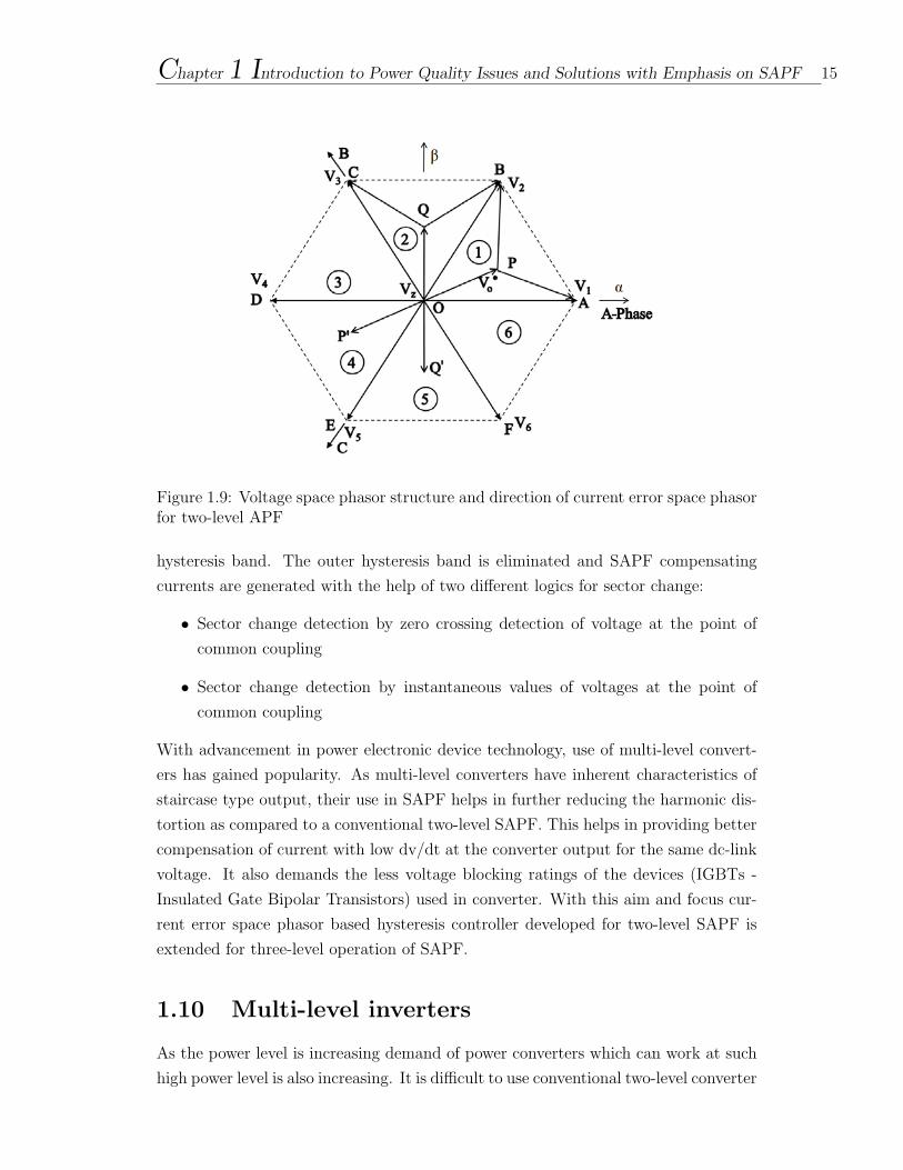
Figure 1.9: Voltage space phasor structure and direction of current error space phasorfor two-level APF
hysteresis band. The outer hysteresis band is eliminated and SAPF compensating
currents are generated with the help of two different logics for sector change:
• Sector change detection by zero crossing detection of voltage at the point of
common coupling
• Sector change detection by instantaneous values of voltages at the point of
common coupling
With advancement in power electronic device technology, use of multi-level convert-
ers has gained popularity. As multi-level converters have inherent characteristics of
staircase type output, their use in SAPF helps in further reducing the harmonic dis-
tortion as compared to a conventional two-level SAPF. This helps in providing better
compensation of current with low dv/dt at the converter output for the same dc-link
voltage. It also demands the less voltage blocking ratings of the devices (IGBTs -
Insulated Gate Bipolar Transistors) used in converter. With this aim and focus cur-
rent error space phasor based hysteresis controller developed for two-level SAPF is
extended for three-level operation of SAPF.
1.10 Multi-level inverters
As the power level is increasing demand of power converters which can work at such
high power level is also increasing. It is difficult to use conventional two-level converter
Chapter 1 Introduction to Power Quality Issues and Solutions with Emphasis on SAPF 16
at high power levels. In order to overcome this problem multi-level inverters are used
at high power levels. Due to this application of multi-level inverter has recently
increased in diversified fields like industries, power system, hybrid vehicles and many
more. Multi-level inverters generate output voltage with stepped waveform with the
help of a number of power semiconductor devices and capacitor voltage sources [60]-
[61]. Multi-level inverters start with three level inverter topology [62]. As the output
of such inverters is a staircase type waveform, initially the aim was to reduce the
harmonic content of generated current or voltage waveforms. Then the multi-level
inverters application was extended to motor drive applications and now they are
extensively used in high power applications [60]. Advantages of multi-level inverters
over conventional two-level inverters are:
• As the output voltage is staircase type waveform total harmonic distortion
(THD) reduces as the number of voltage levels increases.
• Lower voltage rating power semiconductor devices can be used to achieve high
voltage levels at inverter output.
• As the output voltage is stepped waveform dv/dt stress and EMI problems are
reduced.
• Multilevel inverter draw input current with less distortion.
• Multilevel inverters generate less common mode voltage as a result of which
bearing current and hence stress on bearing is less.
• Lower switching frequency operation of multilevel inverter is possible, due to
which switching losses are reduced.
At the same time as the level increases number of power semiconductor devices and
hence complexity of their control increases which is a drawback of multi-level inverters.
Voltage unbalance of dc-link capacitors is also one of the disadvantages of multi-level
inverter structure.
Multi-level inverters are basically of three types:
• Cascaded H-bridge type.
• Neutral-point clamped (NPC) or Diode-clamped.
• Flying capacitor type
Chapter 1 Introduction to Power Quality Issues and Solutions with Emphasis on SAPF 17
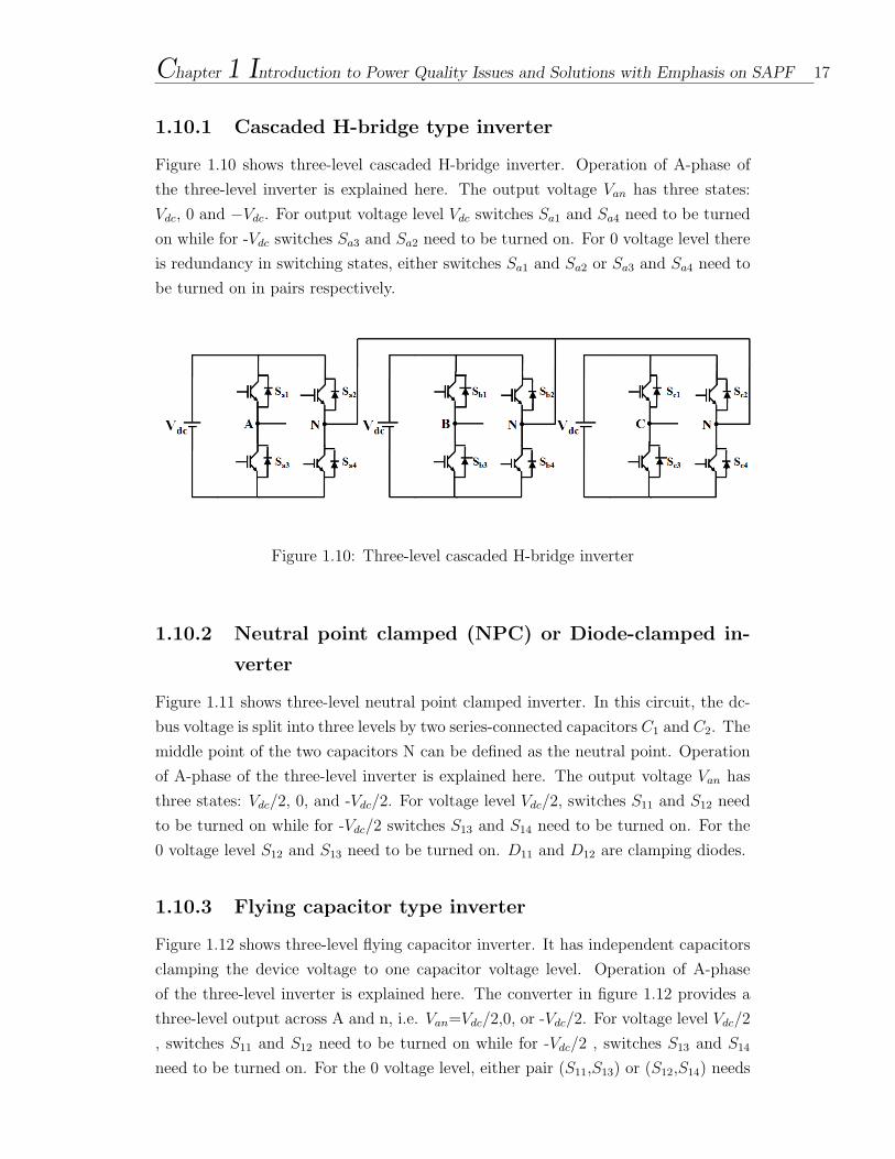
1.10.1 Cascaded H-bridge type inverter
Figure 1.10 shows three-level cascaded H-bridge inverter. Operation of A-phase of
the three-level inverter is explained here. The output voltage Van has three states:
Vdc, 0 and −Vdc. For output voltage level Vdc switches Sa1 and Sa4 need to be turned
on while for -Vdc switches Sa3 and Sa2 need to be turned on. For 0 voltage level there
is redundancy in switching states, either switches Sa1 and Sa2 or Sa3 and Sa4 need to
be turned on in pairs respectively.
Figure 1.10: Three-level cascaded H-bridge inverter
1.10.2 Neutral point clamped (NPC) or Diode-clamped in-
verter
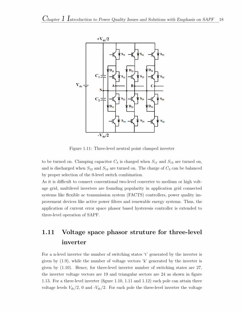
Figure 1.11 shows three-level neutral point clamped inverter. In this circuit, the dc-
bus voltage is split into three levels by two series-connected capacitors C1 and C2. The
middle point of the two capacitors N can be defined as the neutral point. Operation
of A-phase of the three-level inverter is explained here. The output voltage Van has
three states: Vdc/2, 0, and -Vdc/2. For voltage level Vdc/2, switches S11 and S12 need
to be turned on while for -Vdc/2 switches S13 and S14 need to be turned on. For the
0 voltage level S12 and S13 need to be turned on. D11 and D12 are clamping diodes.
1.10.3 Flying capacitor type inverter
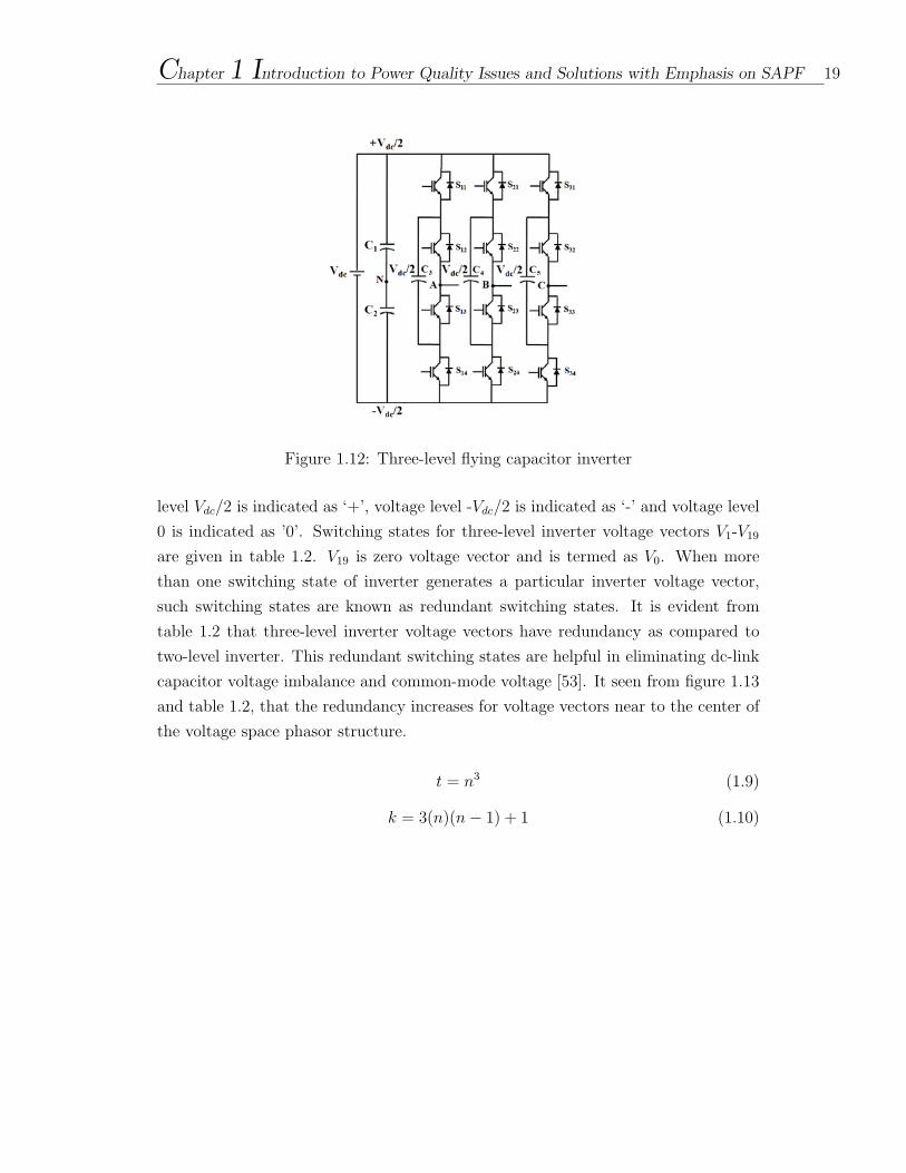
Figure 1.12 shows three-level flying capacitor inverter. It has independent capacitors
clamping the device voltage to one capacitor voltage level. Operation of A-phase
of the three-level inverter is explained here. The converter in figure 1.12 provides a
three-level output across A and n, i.e. Van=Vdc/2,0, or -Vdc/2. For voltage level Vdc/2
, switches S11 and S12 need to be turned on while for -Vdc/2 , switches S13 and S14
need to be turned on. For the 0 voltage level, either pair (S11,S13) or (S12,S14) needs
Chapter 1 Introduction to Power Quality Issues and Solutions with Emphasis on SAPF 18
Figure 1.11: Three-level neutral point clamped inverter
to be turned on. Clamping capacitor C3 is charged when S11 and S13 are turned on,
and is discharged when S12 and S14 are turned on. The charge of C3 can be balanced
by proper selection of the 0-level switch combination.
As it is difficult to connect conventional two-level converter to medium or high volt-
age grid, multilevel inverters are founding popularity in application grid connected
systems like flexible ac transmission system (FACTS) controllers, power quality im-
provement devices like active power filters and renewable energy systems. Thus, the
application of current error space phasor based hysteresis controller is extended to
three-level operation of SAPF.
1.11 Voltage space phasor struture for three-level
inverter
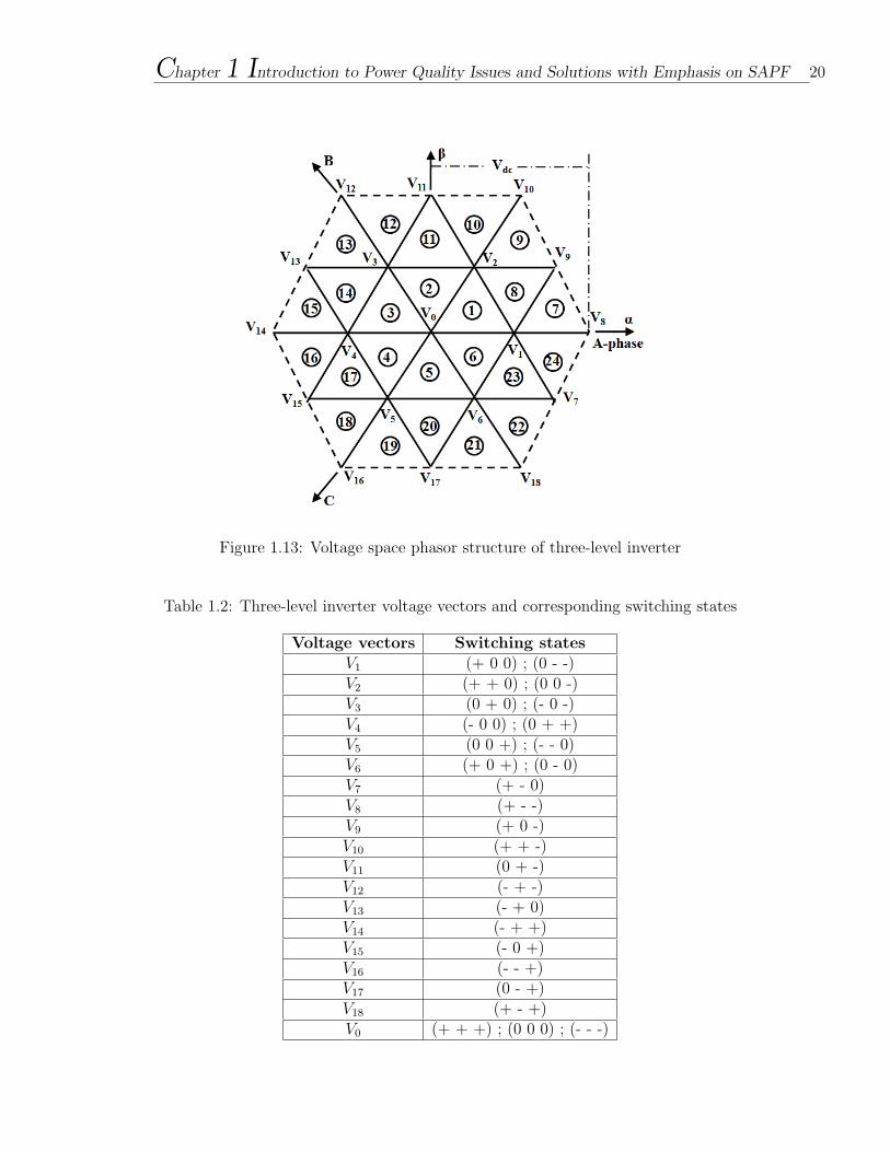
For a n-level inverter the number of switching states ‘t’ generated by the inverter is
given by (1.9), while the number of voltage vectors ‘k’ generated by the inverter is
given by (1.10). Hence, for three-level inverter number of switching states are 27,
the inverter voltage vectors are 19 and triangular sectors are 24 as shown in figure
1.13. For a three-level inverter (figure 1.10, 1.11 and 1.12) each pole can attain three
voltage levels Vdc/2, 0 and -Vdc/2. For each pole the three-level inverter the voltage
Chapter 1 Introduction to Power Quality Issues and Solutions with Emphasis on SAPF 19
Figure 1.12: Three-level flying capacitor inverter
level Vdc/2 is indicated as ‘+’, voltage level -Vdc/2 is indicated as ‘-’ and voltage level
0 is indicated as ’0’. Switching states for three-level inverter voltage vectors V1-V19
are given in table 1.2. V19 is zero voltage vector and is termed as V0. When more
than one switching state of inverter generates a particular inverter voltage vector,
such switching states are known as redundant switching states. It is evident from
table 1.2 that three-level inverter voltage vectors have redundancy as compared to
two-level inverter. This redundant switching states are helpful in eliminating dc-link
capacitor voltage imbalance and common-mode voltage [53]. It seen from figure 1.13
and table 1.2, that the redundancy increases for voltage vectors near to the center of
the voltage space phasor structure.
t = n3 (1.9)
k = 3(n)(n− 1) + 1 (1.10)
Chapter 1 Introduction to Power Quality Issues and Solutions with Emphasis on SAPF 20
Figure 1.13: Voltage space phasor structure of three-level inverter
Table 1.2: Three-level inverter voltage vectors and corresponding switching states
Voltage vectors Switching statesV1 (+ 0 0) ; (0 - -)V2 (+ + 0) ; (0 0 -)V3 (0 + 0) ; (- 0 -)V4 (- 0 0) ; (0 + +)V5 (0 0 +) ; (- - 0)V6 (+ 0 +) ; (0 - 0)V7 (+ - 0)V8 (+ - -)V9 (+ 0 -)V10 (+ + -)V11 (0 + -)V12 (- + -)V13 (- + 0)V14 (- + +)V15 (- 0 +)V16 (- - +)V17 (0 - +)V18 (+ - +)V0 (+ + +) ; (0 0 0) ; (- - -)
Chapter 1 Introduction to Power Quality Issues and Solutions with Emphasis on SAPF 21
1.12 Current error space phasor based hysteresis
controller for three-level shunt active power
filter
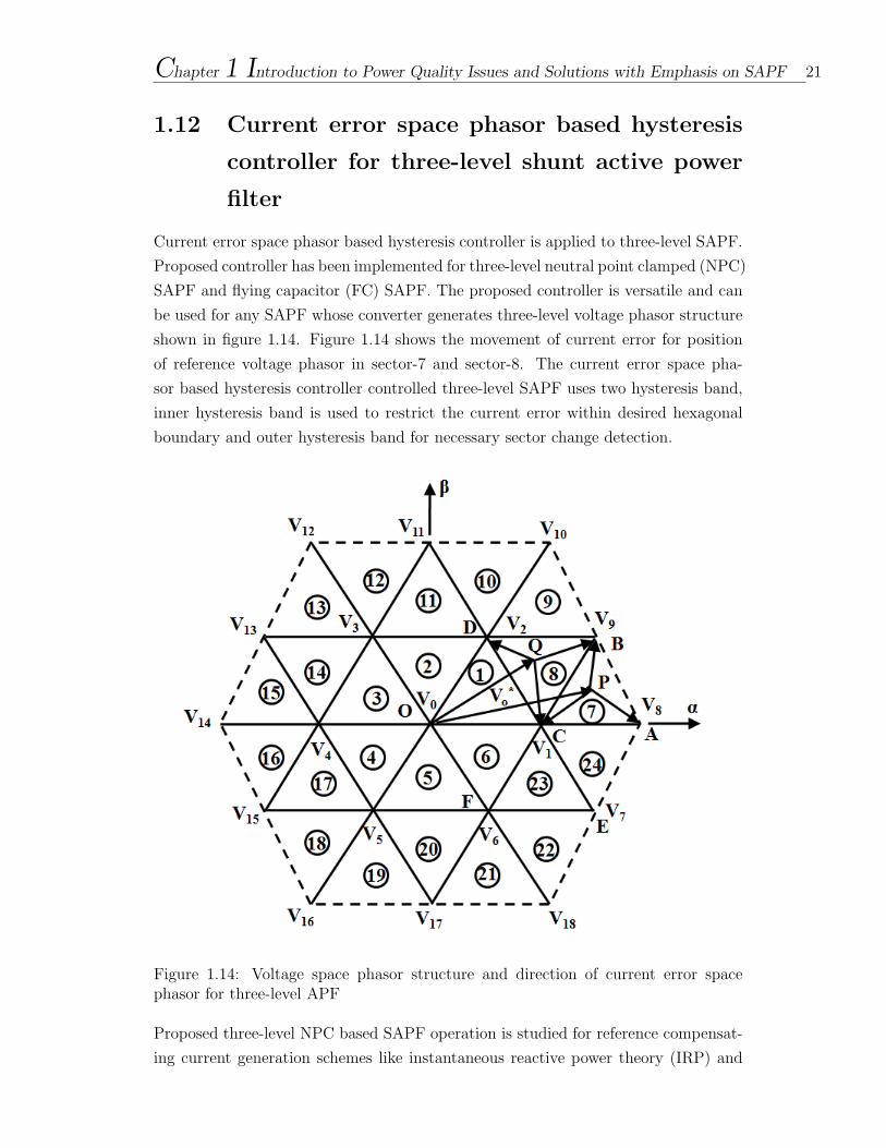
Current error space phasor based hysteresis controller is applied to three-level SAPF.
Proposed controller has been implemented for three-level neutral point clamped (NPC)
SAPF and flying capacitor (FC) SAPF. The proposed controller is versatile and can
be used for any SAPF whose converter generates three-level voltage phasor structure
shown in figure 1.14. Figure 1.14 shows the movement of current error for position
of reference voltage phasor in sector-7 and sector-8. The current error space pha-
sor based hysteresis controller controlled three-level SAPF uses two hysteresis band,
inner hysteresis band is used to restrict the current error within desired hexagonal
boundary and outer hysteresis band for necessary sector change detection.
Figure 1.14: Voltage space phasor structure and direction of current error spacephasor for three-level APF
Proposed three-level NPC based SAPF operation is studied for reference compensat-
ing current generation schemes like instantaneous reactive power theory (IRP) and

Chapter 1 Introduction to Power Quality Issues and Solutions with Emphasis on SAPF 22
dc-link voltage regulation scheme. The SAPF compensates the current harmonics ef-
ficiently. In application of IRP theory, issue of dc-link voltage imbalance is reported.
Hence to overcome this issue dc-link voltage regulation scheme is used for proposed
three-level SAPF. This helps in regulating the dc-link of SAPF, but as dc-link is
split with the help of two capacitors, problem of individual dc-link capacitor voltage
imbalance still persist causing imbalance in SAPF output voltage. Separate voltage
balancing circuitry and control algorithm would be required to eliminate this problem.
In order to overcome this issue, the proposed controller is applied to three-level flying
capacitor SAPF as its dc-link is not split in to two capacitors. A problem of clamping
capacitor voltage imbalance is encountered. The same is solved using appropriate
logic for switching of SAPF by effectively utilizing the redundancy of switching states.
Proposed flying capacitor SAPF operates effectively keeping the current error within
the desired hexagonal boundary.
1.13 Motivation of the work
Power demand of the world is ever increasing and with this increased demand comes
increased problem of current harmonics. Thus harmonic elimination is a serious issue
which cannot be neglected and hence becomes an area of research that should be
dealt with utmost priority which in turn would help in solving the power quality
problems of power system. Hence it is evident that APF, especially shunt APF have
a very crucial role to play in today’s and future’s power system as it mitigates current
harmonics. Thus continuous research work should be done for improving performance
of Shunt APF.
1.14 Scope of the work
Many researchers have been working actively to contribute in the field of active power
filters. Researchers have put their keen efforts to extend the application of APF
from harmonic compensation to harmonic damping, harmonic isolation, harmonic
termination, reactive-power control for power factor correction and voltage regulation,
load balancing, voltage-flicker reduction, and/or their combinations. Work is also
reported on development of novel and efficient techniques for generating reference
compensation current like; instantaneous reactive power theory, synchronous reference
frame method, Fryze current computation, dc-link voltage control method, notch filter
technique, sliding mode control, predictive scheme, state feedback scheme, fast Fourier
transform method, etc.
Selection of current controller (current control strategy) affects the performance of
Chapter 1 Introduction to Power Quality Issues and Solutions with Emphasis on SAPF 23
SAPF. In order to achieve effective compensation of current harmonics, the SAPF
current should track the reference compensating current. The job of current controller
is to force the SAPF current (actual compensating current) to follow the reference
compensating current. Amongst different types of current controllers, hysteresis cur-
rent controllers are widely used in SAPFs, due to their inherent implementation sim-
plicity and fast dynamic response. Conventional hysteresis current controller (HCC)
scheme used in APFs uses three independent hysteresis controllers one for each phase
and hence suffers from lack of coordination between the three individual HCCs. This
results in the basic drawbacks of conventional HCCs, such as higher number of switch-
ing and selection of non adjacent (random) voltage vectors. They also suffer from
drawbacks like limit cycle oscillations, overshoot in current error and generation of
sub-harmonic components in current.
In order to get rid of limit cycle oscillations, space vector modulation technique is
applied to current hysteresis controller which enables the use of zero switching vec-
tor along with nonzero vectors. Researchers have worked upon application of space
vector modulation based hysteresis current controllers for control of SAPF [56]-[59].
Current error space phasor based hysteresis controller is more popularly used in vari-
able frequency drive application of induction motors [40]-[55]. This is basically to
control the voltage source inverter (VSI) with current controlled pulse width modu-
lation (CC-PWM) for high performance drives (HPDs) employing induction motors.
This controller allows the current error space phasor to move within a specified fixed
boundary.
In the field of active power filters main focus till now has been on development of
novel techniques for reference compensating current generation in order to improve the
compensation characteristic. The proposed research work is focused on development
of self-adaptive current controller which overcomes the drawbacks of random voltage
vector selection, and limit cycle oscillations encountered in conventional hysteresis
controllers used for SAPF. The research also focuses on the extension of the same
current controller for high power applications of SAPF by using multi-level converter
topologies for SAPF.
1.15 Outline of the thesis
The thesis is structured in a total of eight chapters preceded by list of symbols, list
of abbreviations, list of figures and list of tables. Chapter - 1 gives introduction
and background of the research work. This chapter addresses motivation and scope
of the work done. Chapter - 2 provides in depth literature survey for the research
work carried out. Chapter - 3 discusses about the shunt active power filter and
Chapter 1 Introduction to Power Quality Issues and Solutions with Emphasis on SAPF 24
the reference compensating current generation methods used. It also presents the
design considerations for the converter of proposed SAPF. Chapter - 4 explains the
working of proposed current error space phasor based hysteresis controller for two-level
SAPF. Chapter - 5 presents the simulation results and analysis of current error space
phasor based hysteresis controller for two-level shunt SAPF. Chapter - 6 explains
the working of current error space phasor based hysteresis controller for three-level
SAPF. Hardware implementation considerations and experimental results of current
error space phasor based hysteresis controller for two-level shunt APF are presented
and discussed in Chapter - 7. Chapter - 8 presents the summary of the results achieved
and conclusion of the research work. It also includes scope for future work. These
chapters are followed by references and list of publications from proposed research
work.
∗ ∗ ∗ ∗ ∗