chapter 1 practical approaches for x-ray crystallography: from …€¦ · in situ x-ray...
TRANSCRIPT
CHAPTER 1
Practical Approaches forIn Situ X-ray Crystallography:from High-throughputScreening to Serial DataCollection
ISABELLE MARTIEL,a VINCENT OLIERIC,a MARTIN CAFFREYb
AND MEITIAN WANG*a
a Swiss Light Source, Paul Scherrer Institute, CH-5232 Villigen,Switzerland; b Membrane Structural and Functional Biology Group,Schools of Medicine and Biochemistry and Immunology, Trinity College,Dublin, Ireland*Email: [email protected]
1.1 Introduction
1.1.1 What Exactly Is In Situ?
In macromolecular crystallography (MX), in situ data collection refers to adiffraction measurement performed on crystals where and as they grow.In other words, the crystals are not harvested individually from their growthenvironment, as is typically done in standard MX with a harvesting loop.Thus, in the in situ experiment, the original growth medium and the
Chemical Biology No. 8Protein Crystallography: Challenges and Practical SolutionsEdited by Konstantinos Beis and Gwyndaf Evansr The Royal Society of Chemistry 2018Published by the Royal Society of Chemistry, www.rsc.org
1
Dow
nloa
ded
on 2
1/06
/201
8 13
:38:
13.
Publ
ishe
d on
19
June
201
8 on
http
://pu
bs.r
sc.o
rg |
doi:1
0.10
39/9
7817
8801
0504
-000
01
crystallization compartment remain in place surrounding the crystal duringinterrogation with the X-ray beam. By contrast, both are removed or min-imized in classical loop harvesting protocols to increase diffraction signal-to-noise ratio (SNR) by minimizing background scattering. In the strictestembodiment of an in situ experiment, the crystal growth plate or chambermust remain hermetically sealed from the moment the crystallization ex-periment is set up and data collection must be done at growth temperature.However, many so-called in situ measurements are made under conditionsdeparting to varying degrees from this limiting definition.
A few examples illustrate the extent to which the in situ label has beenused. Jet sample delivery developed at X-ray free electron laser (XFEL)facilities has been considered an in situ-like method. In this case,microcrystals remain suspended in the mother liquor or the lipid cubicphase (LCP) where they grew. However, these samples have been trans-ferred between syringes and reservoirs, sometimes filtered, and finallyextruded under pressure into an X-ray chamber that is sometimes undervacuum. These post-growth handling steps accompanied by variations inpressure and temperature can mean that data is collected under con-ditions that are far removed from in situ. Several methods, sometimespresented as in situ methods, include a mother liquor removal step, suchas the Crystal Direct approach1 (see Section 1.2) and several XFEL solidsupport sample preparation methods, where the mother liquor is blotted2
or sucked away3 to help position crystals into ordered wells. This motherliquor removal distinguishes these preparation methods from in situexperiments.
In this chapter, after a general introduction to in situ experiments(Section 1.1), we will cover the different in situ setups and the evolution ofthe field, following a historical perspective. In situ experiments date back tothe period where X-ray capillaries were used to grow crystals by micro-dialysis and interface diffusion methods, in order to avoid the difficultiesof transferring grown crystals into capillaries for data collection.4 Howevercrystal movement in the capillary often made the technique impractical.5
In the 1990s, Garcıa-Ruiz and coworkers formalized gel-acupuncturemethods to collect data on in situ counter-diffusion grown crystals incapillaries without any post-growth transfer, at room temperature andunder cryogenic conditions.4,5 In 2004, Jacquamet, Ferrer and coworkersdemonstrated the first in situ capable automated setup at a synchrotronbeamline, where SBS-format crystallization plates were placed in the beamby a robot arm.6 The automated handling of SBS-format plates has spreadin many synchrotron facilities as well as to laboratory X-ray instrumentssince then (Section 1.2), benefiting in particular the field of virus crystal-lography.7 An intense period of development of in situ-specific setupsstarted in parallel, towards format reduction, microfluidic and on-chipsystems (Section 1.3). The latest phase of development has seen theemergence of in situ experiments optimized for serial crystallography andcompatible with data collection at cryogenic temperature (Section 1.4).
2 Chapter 1
Dow
nloa
ded
on 2
1/06
/201
8 13
:38:
13.
Publ
ishe
d on
19
June
201
8 on
http
://pu
bs.r
sc.o
rg |
doi:1
0.10
39/9
7817
8801
0504
-000
01View Online
1.1.2 Goals of In Situ Experiments
In situ methods can be used for a variety of purposes at different stages ofa project. In the phase of optimizing crystallization conditions, in situscreening can help distinguish between protein and salt or small moleculecrystals, as a complement to UV fluorescence and second-order harmonicgeneration techniques.8 The unique advantage of X-ray screening is thedirect access to data collection-relevant information such as diffractionquality, space group and unit cell, which are not provided by optical tech-niques. In situ screening can therefore help to identify genuine proteincrystal hits, to find the best diffracting crystal form in the case of poly-morphs, or in the search of different space groups,9 and to diagnose for lossof diffraction quality due to crystal manipulation and/or cryo-cooling. In situscreening can help increase the efficiency of the protein-to-structure pipelineby enabling diffraction-based identification of best conditions and ligandbinding state. This is especially valuable for drug discovery applicationsinvolving ligand screening.10,11
In situ experiments are not limited to screening and optimization. In someprojects they are used for final data collection and structure solution. This isthe case for crystals that cannot be handled with a loop (crystal degradationupon opening of the well or during harvesting) or flash-cooled in liquidnitrogen, e.g. in virus crystallography,7 or for very small crystals, such as virusand in meso-grown membrane protein crystals, where harvesting hundredsof crystals for serial crystallography is time-consuming and may not bepractical (see Section 1.4). Due to limitations in the tolerable X-ray dose atroom temperature and geometrical constraints imposed by some crystal-lization containers, it is almost impossible to collect a complete data setfrom a single crystal in certain in situ setups, as is usually done in standardcryo-crystallography. Accordingly, partial data sets from several crystals mustbe combined as practiced in micro- and serial crystallography.12 Dependingon the sample type, data collection can be performed either using a multi-crystal approach or using serial crystallography methods.13 In the multi-crystal approach, a few partial data sets covering significant angular wedgesfrom a few crystals are merged together. The sorting and merging of data setsare generally performed manually or semi-manually by the crystallographer.In the serial approach, large numbers of small wedges or even still imagesfrom many crystals are assembled, which requires automation in data setprocessing, selection and merging. The serial approach derives from serialfemtosecond crystallography (SFX) data collection, where only still imagesare collected on thousands of randomly oriented small crystals.14,15 Insynchrotron-based serial data collection, wedges of typically a few degreesare collected on each crystal. In both cases, data collection of a completedata set relies on the varied or random orientation of crystals for adequatesampling of reciprocal space. Preferential orientation of the crystals on theplate or well surface is therefore to be minimized or compensated for bytilting the sample support during X-ray data collection.
Practical Approaches for In Situ X-ray Crystallography 3
Dow
nloa
ded
on 2
1/06
/201
8 13
:38:
13.
Publ
ishe
d on
19
June
201
8 on
http
://pu
bs.r
sc.o
rg |
doi:1
0.10
39/9
7817
8801
0504
-000
01View Online
With in situ methods, unnecessary manipulation of crystals by harvestingis avoided. However, harvesting is not always detrimental: clear caseswhere post-growth treatments such as dehydration increase the diffractingquality have been reported.16 Methods for controlled dehydration and otherpost-growth treatments in in situ plates have been developed.17 Anothercharacteristic of manual harvesting is the introduction of a possible sourceof irreproducibility in the experiment, since two crystals are rarely harvestedexactly in the same way, even by the same person. This is less of an issue within situ methods.
Historically, in situ measurements are performed mainly at roomtemperature (RT) (see Section 1.2). RT data collection is often deemedbiologically more relevant. Further, it enables the probing of conformationallandscapes, time-resolved studies and chemical reactions in the crystals.Measurements at RT usually result in lower crystal mosaicity. In certaincases, such as with virus crystals, RT data collection is the only option dueto crystal fragility and sensitivity to cryo-cooling. Recent developmentswith thin-film samples (see Section 1.4.1) offer the possibility to performflash-cooling of in situ samples and to collect data under cryogenic con-ditions. Cryo-treatment is not compliant with the strict definition of in situ,but low temperature (100 K) data collection has significant advantages thatinclude a 50- to 100-fold increase of the tolerable dose. Further, cryo-cooledsamples are easily stored and transported.
1.1.3 Challenges of In Situ Methods
Here we list the challenges related to in situ experiments, of which usersshould be aware when selecting a particular method and planning experi-ments. The first and foremost challenge is the relatively high scatteringbackground arising from the support and the growth medium surroundingthe crystal. This generally results in sharp or diffuse scattering rings or arcsat intermediate-to-low scattering angles (B3–6 Å). Although in situ setups areusually optimized to reduce such scatter (see Section 1.1.4), backgroundcontribution will remain larger for most in situ setups compared to a cor-rectly loop-harvested cryo-cooled crystal.
The second challenge, radiation damage, is not specific to in situexperiments. Detecting and managing radiation damage is also crucial forsuccessful data collection with conventional methods.18 With in situmethods, the problem of radiation damage is pronounced when datacollection is done at RT and/or with small crystals. At RT, the tolerable doseper crystal is of the order of a fraction of a MGy,19 while under cryogenicconditions at 100 K a single crystal can take up to about 20 MGy (theso-called Henderson limit20,21) for molecular replacement methods, or about5 MGy for experimental phasing methods.22 In practice, these should beconsidered as upper dose limits, since many crystals are more sensitive,23 ina manner that depends on heavy atom content, crystal composition andcrystallization conditions.
4 Chapter 1
Dow
nloa
ded
on 2
1/06
/201
8 13
:38:
13.
Publ
ishe
d on
19
June
201
8 on
http
://pu
bs.r
sc.o
rg |
doi:1
0.10
39/9
7817
8801
0504
-000
01View Online
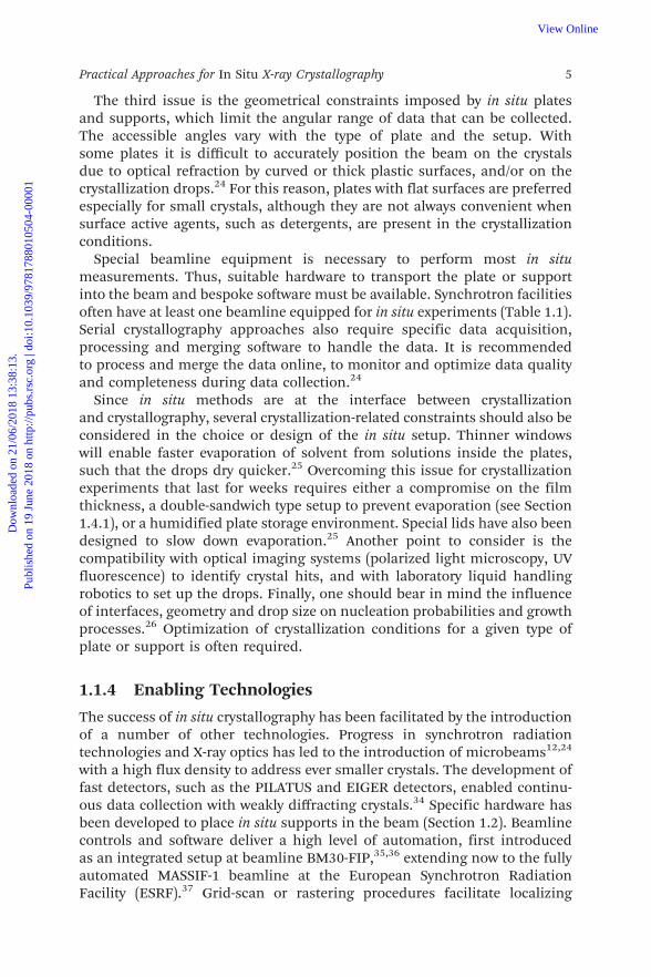
The third issue is the geometrical constraints imposed by in situ platesand supports, which limit the angular range of data that can be collected.The accessible angles vary with the type of plate and the setup. Withsome plates it is difficult to accurately position the beam on the crystalsdue to optical refraction by curved or thick plastic surfaces, and/or on thecrystallization drops.24 For this reason, plates with flat surfaces are preferredespecially for small crystals, although they are not always convenient whensurface active agents, such as detergents, are present in the crystallizationconditions.
Special beamline equipment is necessary to perform most in situmeasurements. Thus, suitable hardware to transport the plate or supportinto the beam and bespoke software must be available. Synchrotron facilitiesoften have at least one beamline equipped for in situ experiments (Table 1.1).Serial crystallography approaches also require specific data acquisition,processing and merging software to handle the data. It is recommendedto process and merge the data online, to monitor and optimize data qualityand completeness during data collection.24
Since in situ methods are at the interface between crystallizationand crystallography, several crystallization-related constraints should also beconsidered in the choice or design of the in situ setup. Thinner windowswill enable faster evaporation of solvent from solutions inside the plates,such that the drops dry quicker.25 Overcoming this issue for crystallizationexperiments that last for weeks requires either a compromise on the filmthickness, a double-sandwich type setup to prevent evaporation (see Section1.4.1), or a humidified plate storage environment. Special lids have also beendesigned to slow down evaporation.25 Another point to consider is thecompatibility with optical imaging systems (polarized light microscopy, UVfluorescence) to identify crystal hits, and with laboratory liquid handlingrobotics to set up the drops. Finally, one should bear in mind the influenceof interfaces, geometry and drop size on nucleation probabilities and growthprocesses.26 Optimization of crystallization conditions for a given type ofplate or support is often required.
1.1.4 Enabling Technologies
The success of in situ crystallography has been facilitated by the introductionof a number of other technologies. Progress in synchrotron radiationtechnologies and X-ray optics has led to the introduction of microbeams12,24
with a high flux density to address ever smaller crystals. The development offast detectors, such as the PILATUS and EIGER detectors, enabled continu-ous data collection with weakly diffracting crystals.34 Specific hardware hasbeen developed to place in situ supports in the beam (Section 1.2). Beamlinecontrols and software deliver a high level of automation, first introducedas an integrated setup at beamline BM30-FIP,35,36 extending now to the fullyautomated MASSIF-1 beamline at the European Synchrotron RadiationFacility (ESRF).37 Grid-scan or rastering procedures facilitate localizing
Practical Approaches for In Situ X-ray Crystallography 5
Dow
nloa
ded
on 2
1/06
/201
8 13
:38:
13.
Publ
ishe
d on
19
June
201
8 on
http
://pu
bs.r
sc.o
rg |
doi:1
0.10
39/9
7817
8801
0504
-000
01View Online
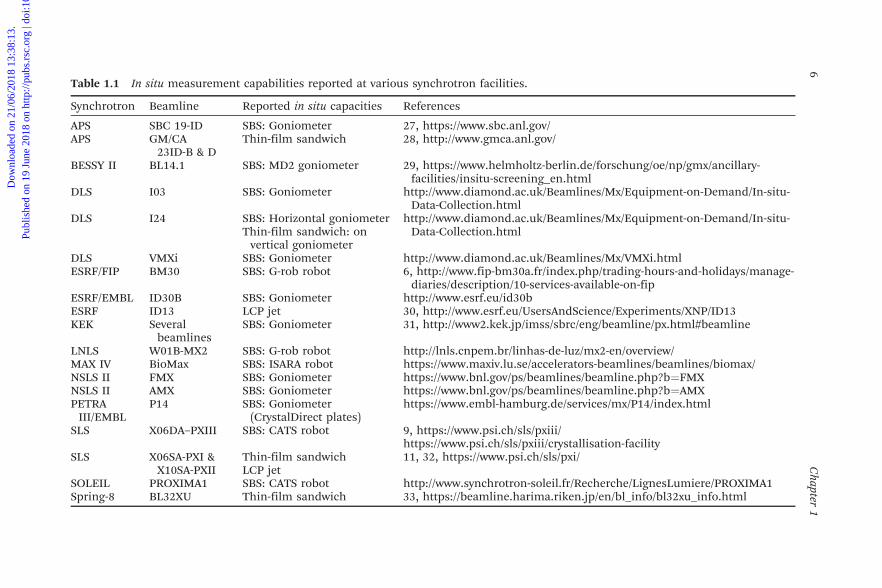
Table 1.1 In situ measurement capabilities reported at various synchrotron facilities.
Synchrotron Beamline Reported in situ capacities References
APS SBC 19-ID SBS: Goniometer 27, https://www.sbc.anl.gov/APS GM/CA
23ID-B & DThin-film sandwich 28, http://www.gmca.anl.gov/
BESSY II BL14.1 SBS: MD2 goniometer 29, https://www.helmholtz-berlin.de/forschung/oe/np/gmx/ancillary-facilities/insitu-screening_en.html
DLS I03 SBS: Goniometer http://www.diamond.ac.uk/Beamlines/Mx/Equipment-on-Demand/In-situ-Data-Collection.html
DLS I24 SBS: Horizontal goniometer http://www.diamond.ac.uk/Beamlines/Mx/Equipment-on-Demand/In-situ-Data-Collection.htmlThin-film sandwich: on
vertical goniometerDLS VMXi SBS: Goniometer http://www.diamond.ac.uk/Beamlines/Mx/VMXi.htmlESRF/FIP BM30 SBS: G-rob robot 6, http://www.fip-bm30a.fr/index.php/trading-hours-and-holidays/manage-
diaries/description/10-services-available-on-fipESRF/EMBL ID30B SBS: Goniometer http://www.esrf.eu/id30bESRF ID13 LCP jet 30, http://www.esrf.eu/UsersAndScience/Experiments/XNP/ID13KEK Several
beamlinesSBS: Goniometer 31, http://www2.kek.jp/imss/sbrc/eng/beamline/px.html#beamline
LNLS W01B-MX2 SBS: G-rob robot http://lnls.cnpem.br/linhas-de-luz/mx2-en/overview/MAX IV BioMax SBS: ISARA robot https://www.maxiv.lu.se/accelerators-beamlines/beamlines/biomax/NSLS II FMX SBS: Goniometer https://www.bnl.gov/ps/beamlines/beamline.php?b=FMXNSLS II AMX SBS: Goniometer https://www.bnl.gov/ps/beamlines/beamline.php?b=AMXPETRA
III/EMBLP14 SBS: Goniometer
(CrystalDirect plates)https://www.embl-hamburg.de/services/mx/P14/index.html
SLS X06DA–PXIII SBS: CATS robot 9, https://www.psi.ch/sls/pxiii/https://www.psi.ch/sls/pxiii/crystallisation-facility
SLS X06SA-PXI &X10SA-PXII
Thin-film sandwich 11, 32, https://www.psi.ch/sls/pxi/LCP jet
SOLEIL PROXIMA1 SBS: CATS robot http://www.synchrotron-soleil.fr/Recherche/LignesLumiere/PROXIMA1Spring-8 BL32XU Thin-film sandwich 33, https://beamline.harima.riken.jp/en/bl_info/bl32xu_info.html
6C
hapter1
Dow
nloa
ded
on 2
1/06
/201
8 13
:38:
13.
Publ
ishe
d on
19
June
201
8 on
http
://pu
bs.r
sc.o
rg |
doi:1
0.10
39/9
7817
8801
0504
-000
01
View Online

crystals invisible by optical methods, identifying the best diffracting crystalsor regions of crystals and performing diffraction-based crystal centering,34,38
lately by an automated analysis of the rastering results.39
With regard to data processing and management, in situ data collection incrystallization plates has been facilitated enormously by powerful multi-crystal merging procedures. Crystal selection40 and clustering methods41,42
have also proven useful, as recently reviewed.43 Data management of theoften large number of crystallization trials has also received attention. Therecent use of haptic interfaces is one such example.44
Early on, great effort was invested in optimizing the materials used tomanufacture in situ plates and supports. The commercial availability of re-cently developed low background, UV-friendly specialty polymers, mainly cyclicolefin (co-)polymers, in industrial grades of suitable quality, thickness andaffordability, has been integral to the success of the approach.45 The designof new high-throughput in situ consumables often involves materials opti-mization and polymer processing. The success of a new in situ method is alsooften correlated to the translation into commercially available consumables,and the establishment of user-friendly, easily reproducible protocols.11,32
1.2 In Situ Screening at the Synchrotron: StandardSBS Plates
1.2.1 Development History
The first demonstration of automated in situ experiments on SBS-formatplates, by Jean-Luc Ferrer and coworkers at the FIP-BM30A (French beamlinefor Investigation of Proteins) at the ESRF in 2004, opened a new paradigmfor in situ experiments, inaugurating the era of high-throughput in situmethods. Jacquamet, Ferrer and coworkers6 developed beamline hardwareand software to perform in situ data collection directly in the crystallizationplate in an easy and efficient manner (Figure 1.1). The SBS format formicroplates was established around the year 2000 by the Society forBiomolecular Screening (SBS), now part of the Society for LaboratoryAutomation and Screening (SLAS), and the American National StandardsInstitute (ANSI). The goal was to ensure compatibility between plates fromdifferent manufacturers and laboratory automation instrumentation fordrug discovery research. The 96-well SBS plates are therefore compatiblewith laboratory robotics used for drop setting in crystallization experimentsand are now ubiquitous in crystallization laboratories. Although in situexperiments in SBS plates started mainly as a screening tool and are oftencalled ‘in situ plate screening’, the collection of complete data sets wasperformed early on, first on single high symmetry crystals6 and then bymerging data from a small number of crystals.45 Serial-like data collection ofsmall wedges from a large number of crystals was also later demonstrated.46
In situ data collection has been particularly beneficial in structural biologyfields where crystals are fragile and difficult to flash-cool. For instance, virus
Practical Approaches for In Situ X-ray Crystallography 7
Dow
nloa
ded
on 2
1/06
/201
8 13
:38:
13.
Publ
ishe
d on
19
June
201
8 on
http
://pu
bs.r
sc.o
rg |
doi:1
0.10
39/9
7817
8801
0504
-000
01View Online
crystals have large unit cells and weak crystal contacts and are notoriouslyfragile. It is often difficult to find suitable cryo-cooling conditions for suchcrystals, and the increase of mosaicity often observed upon cryo-cooling canresult in spot overlap due to the large unit cell. For these reasons, most virusstructures determined by X-ray crystallography are based on data collectionat RT.7,24,47
Efforts are underway to make in situ plate experiments suitable for ligandscreening applications. This includes fragment-based screening, which gen-erally involves large numbers of crystals. Well-diffracting crystals are grownunder identical crystallization conditions and are soaked (or co-crystallized)using a library of chemical ligands to determine the degree of binding. Forfragment-based screening data set collection, high completeness and/ormultiplicity is not always required.45 Ligand addition for in situ-like ligand
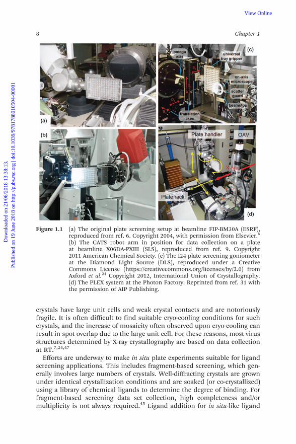
Figure 1.1 (a) The original plate screening setup at beamline FIP-BM30A (ESRF),reproduced from ref. 6. Copyright 2004, with permission from Elsevier.6
(b) The CATS robot arm in position for data collection on a plateat beamline X06DA-PXIII (SLS), reproduced from ref. 9. Copyright2011 American Chemical Society. (c) The I24 plate screening goniometerat the Diamond Light Source (DLS), reproduced under a CreativeCommons License (https://creativecommons.org/licenses/by/2.0) fromAxford et al.24 Copyright 2012, International Union of Crystallography.(d) The PLEX system at the Photon Factory. Reprinted from ref. 31 withthe permission of AIP Publishing.
8 Chapter 1
Dow
nloa
ded
on 2
1/06
/201
8 13
:38:
13.
Publ
ishe
d on
19
June
201
8 on
http
://pu
bs.r
sc.o
rg |
doi:1
0.10
39/9
7817
8801
0504
-000
01View Online
screening experiments can be performed either using standard liquidhandling robots10 or by acoustic droplet ejection (ADE)48 using, for example,the commercial system Labcyte Echo 550, or in-house built setups. The verysmall volumes (down to a few nanoliters) handled by ADE make it possible tomultiply the number of crystallization or soaking trials and therefore toscreen more ligands.48 Gelin et al.10 developed a method where the base ofeach well in the plate is coated with dry ligand. The ligand solubilizes in thedispensed crystallization drop and ideally diffuses into the crystal.
1.2.2 Plate Handling Hardware
Two types of plate handling hardware exist at beamlines for SBS plate in situcollection: robots and goniometers. An automatic sample changer robot,normally used to exchange cryo-cooled samples, can be equipped with aspecial gripper for moving SBS plates to and from a multi-plate hotel. Theprecision and stability of 6-axis industrial robots, commonly used as samplechangers, is sufficient to reliably position the plate, and to center and rotatethe crystal as a goniometer would do on the beam axis – by combining the 6-axis degrees of freedom to emulate a single axis rotation distinct from the 6throtation axis. The robot and beamline control software must also be adaptedto enable these complex motions. The precision achieved upon rotation of awell-centered crystal is excellent, as shown by the small beam footprint lefton a test crystal after a 601 rotation (figure 4D in Pinker and coworkers49).Three examples of this type of system are the commercial CATS,50 ISARAand G-Rob45 systems, in use at SLS, BESSY II, Soleil, Max IV and ESRF FIP(Table 1.1). A second approach is to use a dedicated, standard goniometer tomove and to rotate the plate. The plate screening goniometer can simply bean adaptor on the main goniometer, or it can be distinct from the maingoniometer for single crystal work, in which case fast goniometer switchingprocedures should be in place. The plate is either fixed manually to thegoniometer with an adaptor holder in which the plate is placed or placed byan automatic sample changer. Recent examples (Figure 1.1) of such setupscan be found at beamline I2424,51 of the DLS, or the PLEX system at thePhoton Factory.31 The MD2 diffractometer can also take SBS plates using anadaptor (Table 1.1). SBS plate handling hardware has been developed forlaboratory sources.52 The Rigaku PlateMate system is one such example.
1.2.3 Plate Optimization for In Situ
The importance of the material composition and design of the plate forsuccessful in situ data collection is fully appreciated.6 Both the intensity andresolution of the scattering background must be minimized to increase theSNR. In particular, the background around the resolution limit should beminimized to maximize the SNR at the crystal’s highest resolution.Amorphous materials are often preferred over crystalline or semi-crystallinematerials due to their broader, more diffuse scattering properties.
Practical Approaches for In Situ X-ray Crystallography 9
Dow
nloa
ded
on 2
1/06
/201
8 13
:38:
13.
Publ
ishe
d on
19
June
201
8 on
http
://pu
bs.r
sc.o
rg |
doi:1
0.10
39/9
7817
8801
0504
-000
01View Online
The optical clarity, low birefringence and UV-compatibility, as well as thefabrication-related properties must also be considered. The intensity of thebackground generated by scattering from an amorphous material dependson several material- and geometry-related parameters:53
Ibg / ArVMw
fbg sð Þ2 (1:1)
where A is an absorption factor (which depends on the absorption coefficientmabs and thickness of the material), V is the illuminated volume (equal to theproduct of the beam area and the material thickness), r is the material massdensity and Mw its molecular weight, and fbg is the scattering-angle-dependent structure factor of the material. The proportionality factor, notshown in eqn (1.1), contains factors related to the detector pixel geometryand position, the X-ray beam characteristics, exposure time and physicalconstants. Upon inspection, eqn (1.1) shows that the background can bereduced by decreasing the material thickness, and selecting materials withsuitable absorption and scattering properties, composed preferably of low-Z atoms.
Jacquamet and coworkers6 compared several of the materials available atthe time of their work. They recognized the need for the design of specialin situ plates, with optimized well geometry and plastic thickness. Such anoptimized plate, the Greiner CrystalQuick X45 for sitting-drop experiments,was introduced formally in 2011. The selected material was cyclic olefincopolymer (COC), a specialty plastic with low birefringence properties. Thethickness of the well bottom was reduced to 300 mm, and the well shapeallowed collection over a total angular range up to 801. Later a second in situoptimized SBS plate was introduced, the MiTeGen InSitu-1 plate,54 where thedrops are directly deposited on a flat COC film of thickness 100 mm. Theplates can be used for sitting- or hanging-drop experiments and are com-patible with deposition of multiple drops by ADE. It is important to note thatwater permeability is of concern when using such thin plastic films,meaning that the drops dry faster.25 In the latest in situ plate brought tomarket, the CrystalDirect plate developed at the European Molecular BiologyLaboratory (EMBL) and available from MiTeGen, the COC film thickness hasbeen reduced to 25 mm. The CrystalDirect plate is designed to be compatiblewith the automated harvesting system of the same name. Here the excessmother liquor is aspirated through a small hole, a pin is glued onto the film,laser photoablation is used to cut the film around the crystals and the gluedpin tip and this is followed by immediate flash-cooling.1,55
1.2.4 Automation and Pipeline Integration
Automation compatibility was at the heart of the first plate screening ex-periments in 2004.6 Further developments logically followed. In 2011, thefirst integrated plate screening pipeline was established at the Swiss Light
10 Chapter 1
Dow
nloa
ded
on 2
1/06
/201
8 13
:38:
13.
Publ
ishe
d on
19
June
201
8 on
http
://pu
bs.r
sc.o
rg |
doi:1
0.10
39/9
7817
8801
0504
-000
01View Online
Source (SLS) beamline X06DA-PXIII.9 In this setup, in addition to a simpleshort-term plate hotel inside the hutch, the sample changer has direct accessto the Formulatrix Rock Imager RI 1000 plate hotel located in the adjacentcrystallization facility. A 4-axis robot shuttles the plates through the radi-ation safety wall between the crystallization facility and beamline hutch.Using this automated system, based on the online access of drop imagingresults from the automated imager, users can perform targeted in situdiffraction-based screening of their crystallization plates placed in theincubator without any onsite intervention after the setup of the plate. Thisarrangement facilitates fast feedback on the diffraction quality of the crys-tals, eliminates the need for risky plate transport or shipping, and enablesfully remote plate screening operation. In addition, the X06DA-PXIII setupallows fast (2 minute) exchange by the users between standard cryogenicdata collection and in situ screening mode.
Following this lead, the VMXi beamline,56 a microfocus beamlinededicated fully to in situ plate screening and data collection, has beenconstructed at DLS. Two Formulatrix Rock Imagers set at two differentincubation temperatures are installed in the beamline hutch and are directlyaccessed by the plate changer robot, which is mounted on a large linear axis.A system for maintaining temperature control on the plate during datacollection is also foreseen. This beamline is expected to operate on a fullyautomated basis, where users mark the positions of interest on the imagesfrom the Rock Imager.
1.3 Further Developments: Scale Reduction andMicrofluidics
The SBS format had its origins in automated laboratory equipment for liquidhandling. In parallel to SBS-format in situ developments, there have alsobeen in situ developments that use non-SBS formats, better adapted to datacollection with standard goniometers at synchrotrons. These setups areoften designed for direct data collection rather than screening. The de-parture from the SBS format goes generally in the direction of a format sizereduction, both in the overall footprint, better compatible with crowdedsample environments at beamlines, and in the crystallization trial dimen-sions, as with microfluidic setups. We have here arbitrarily distinguishedbetween small format multi-crystal holders for in situ experiments and moreclassical microfluidics setups.
1.3.1 Small Formats
The X-chip (MiTeGen61) developed by Kisselman et al.57 is a small plasticchip with drop positions marked, where micro-batch under oil crystal-lization trials can be set up (Figure 1.2a,b). Each drop location is definedby concentric hydrophilic–hydrophobic patterned rings, which ensure
Practical Approaches for In Situ X-ray Crystallography 11
Dow
nloa
ded
on 2
1/06
/201
8 13
:38:
13.
Publ
ishe
d on
19
June
201
8 on
http
://pu
bs.r
sc.o
rg |
doi:1
0.10
39/9
7817
8801
0504
-000
01View Online
12 Chapter 1
Dow
nloa
ded
on 2
1/06
/201
8 13
:38:
13.
Publ
ishe
d on
19
June
201
8 on
http
://pu
bs.r
sc.o
rg |
doi:1
0.10
39/9
7817
8801
0504
-000
01View Online
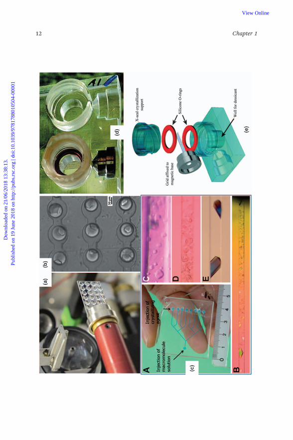
good pinning of the water-based crystallization drop and the oil cover layer.The crystallization drop is typically a 50 : 50 by volume mix of protein andprecipitant solution (B500 nl total volume), covered withB1 ml high viscosityoil (paraffin or a paraffin/silicon oil combination, typically). The drops willevaporate after days to weeks, depending on the oil. The chip itself absorbsabout 30% of the beam (at 12.4 keV) with its 375 mm thickness and the oilcontributing to the absorption and background. Nevertheless, Se-SADphasing data collection was successfully demonstrated using this setup. Todate, all data collection has been done at RT. The chip is fixed on a magneticbase compatible with standard goniometer heads, and the chip dimensionsdo not exceed this footprint, so that the X-chip is in principle compatiblewith any standard beamline setup.
More recently, Baxter et al.60 introduced multi-crystal grids compatiblewith a home-developed tray for in situ crystal growth by vapor diffusion(Figure 1.2d,e). The grids consist of a laser-cut polycarbonate sheet of 100 to200 mm thickness, with an array of holes, backed with a 5 mm polycarbonatefoil. The holes are 125 to 400 mm in diameter. The grids are fixed on standardmagnetic bases. In the in situ setup, the grid holes are filled with the proteinsolution and precipitant mixture, either with a liquid handling robot or byADE. The grids are then installed in the vapor diffusion chamber, sealedwith rubber O-rings and a removable lid. The chamber is opened after crystalgrowth. This type of multi-crystal mount is suitable for goniometer-baseddata collection both at synchrotrons and XFELs.62
ADE-assisted preparation of in situ samples has the potential for ligand orfragment screening experiments, as demonstrated by Yin and coworkerswith in situ experiments set up on micromeshes.63 Previously, Berger andcoworkers64 have shown that it is possible to grow crystals directly in a loopand to cryo-cool them.
1.3.2 Microfluidic Methods for In Situ
Microfluidics is the technique of choice for manipulating small volumes ofliquids in a controlled manner. These in situ setups offer both the possibilityto screen for various crystallization conditions and to collect diffraction data.
Figure 1.2 (a) X-CHIP with 24 wells mounted on a goniometer, reproduced under aCreative Commons License (https://creativecommons.org/licenses/by/2.0)from Kisselman et al.57 Copyright r Kisselman et al. 2011. (b) Droplet-based microfluidic device for Laue diffraction on in situ grown glucoseisomerase crystals, reproduced under a Creative Commons License(https://creativecommons.org/licenses/by/2.0) from Heymann et al.58
Copyright r Michael Heymann et al. 2014. (c) On-chip counter diffusionchip (A), and channels with crystals of thaumatin (B), bovine insulin (C), aplant virus (D) and turkey egg-white lysozyme (E). Reproduced fromDhouib et al.59 with permission from The Royal Society of Chemistry. (d, e)High density multi-crystal grids with in situ tray, reproduced under aCreative Commons License (https://creativecommons.org/licenses/by/2.0)from Baxter et al.60
Practical Approaches for In Situ X-ray Crystallography 13
Dow
nloa
ded
on 2
1/06
/201
8 13
:38:
13.
Publ
ishe
d on
19
June
201
8 on
http
://pu
bs.r
sc.o
rg |
doi:1
0.10
39/9
7817
8801
0504
-000
01View Online
Three types of on-chip crystallization experiments with in situ diffractioncapabilities can be distinguished: free interface diffusion (FID), counter-diffusion and droplet-based batch. Most devices designed for on-chip datacollection use COC as an X-ray-friendly material. However, new materialssuch as graphene have been tested and are of interest for their water-impermeability and ultralow-background properties.65
The main commercial option for FID microfluidics experiments is theTopaz chip in SBS format by Fluidigm,66 which has been reported to bediffraction-compatible.9 The Topaz system relies on the use of pressure-activated valves which bring into contact the preloaded precipitant andprotein solutions, in up to 96 different conditions. FID experiments arecharacterized by small reaction chambers in which equilibration by dif-fusion is achieved relatively quickly and without convective mixing. As aresult, the crystals produced by FID are potentially better ordered, and thetrajectory in the crystallization phase diagram is better controlled comparedto batch experiments.67 Multilayer valve-based microfluidic devices opti-mized for in situ diffraction have also been reported,68 with applications inLaue diffraction69 and for in meso crystal growth.70 Microfluidic FID ex-periments can screen conditions using small volumes, but the devices areusually difficult or expensive to fabricate and require a pump to operate.
Counter-diffusion differs from FID by the establishment of a gradient ofconditions, by diffusion of chemical species over larger distances than inFID. In a single experiment a continuum of crystallization conditions isprobed. Counter-diffusion in capillaries was among the first in situ dif-fraction setups,4,5 and microfluidics soon appeared as a natural scale-downoption, while offering more flexibility for channel design. Two groups, Ngand coworkers71 and Dhouib and coworkers,59 developed in parallel in situcounter-diffusion microfluidic chips. The device by Ng and coworkers71
consists of single channels, and is commercialized by Greiner BioOneunder the name CrystalSlide. Four CrystalSlides can be presented to thebeam in a special SBS-format holder. In the commercial version, individualchannels can be separated and mounted on a magnetic base.72 The device byDhouib and coworkers,59 as well as the ChipX by Pinker and coworkers,49
offers the possibility to screen different precipitant formulations against asingle protein solution via channel branching (Figure 1.2c). The CrystalHarpsystem is an array of polyimide-coated quartz capillaries presented in SBSformat,9 commercialized by Molecular Dimensions.73 Counter-diffusiondevices are generally filled using pipettes, thus not requiring pumpequipment.
Droplet-based microfluidics crystallization experiments are essentiallymicrobatch-under-oil experiments. Each nanoliter trial droplet is separatedfrom the others by a continuum of fluorocarbon oil. The droplets are pro-duced by mixing two or more aqueous solutions, typically protein solution,buffer and precipitant, at the junction where the water-in-oil emulsion iscreated. The droplets are then stored on the device. Pumping equipment andcareful flow or pressure control are required to create the droplets and to vary
14 Chapter 1
Dow
nloa
ded
on 2
1/06
/201
8 13
:38:
13.
Publ
ishe
d on
19
June
201
8 on
http
://pu
bs.r
sc.o
rg |
doi:1
0.10
39/9
7817
8801
0504
-000
01View Online

the crystallization conditions. In the initial in situ droplet-based micro-fluidics measurements,74 droplets were produced in devices made fromPDMS, and stored for data collection in a 180 mm inner diameter glass ca-pillary coupled to the device. For in situ data collection, the capillary con-taining the droplets was cut and sealed, and fixed on a magnetic base. Thecommercial CrystalCard device,75,76 by Protein BioSolutions, works on thesame principle. The crystals produced can be harvested or measured in situ,either directly inside the chip or by coupling with a capillary.77 The PlugMaker system includes the pumping equipment and automated controlsneeded to use the CrystalCard devices. More recently, other X-ray-friendlychips for droplet-based in situ experiments have been designed by Heymannet al.,58 using thin COC films for device fabrication. The suitability of thedevice for serial Laue diffraction data collection at RT was demonstrated.The effects of a confined droplet environment on nucleation and crystal-lization processes were studied in detail.78 It was found that a preliminaryscreening step makes it possible to find conditions where only a singlecrystal per droplet is obtained, which is an optimal situation for data col-lection. This was attributed to a confinement-induced negative feedback onthe nucleation probability after the first nucleus appeared.
1.4 The Emergence of Serial In Situ Data Collection
1.4.1 Thin-film Sandwiches
In recent years, a new class of in situ setups has been developed, that we willrefer to here as thin-film sandwiches to distinguish them from the previouslydescribed in situ setups. The motivation for these new developments is tooffer a user-friendly setup that can be prepared with standard crystallizationequipment and that is compatible with in situ serial crystallography. Theprinciple of thin-film sandwich setups is to perform the crystallization trialin a confined space between two thin, X-ray compatible films. To avoid de-hydration caused by water permeability of the film, the sandwich is enclosedin a second thick glass or plastic sandwich for the duration of the crystal-lization experiment and this is removed just before data collection(Figure 1.3). These methods are appropriately called double-sandwichmethods. The thin-film sandwich plate has an SBS 96-well plate format thatis compatible with laboratory drop setting robotics. In contrast to SBS in situplates (Section 1.2), individual wells can be easily removed from the plate.This allows for direct mounting of wells on standard goniometers. Import-antly, individual wells can be flash-cooled in liquid nitrogen, which extendsin situ crystallography from mainly a screening technique at RT to a routinedata collection method at cryogenic temperature. The wells can be fixed onstandard pins, flash-cooled, shipped in a dry-shipper and mounted on agoniometer with an automated sample changer as commonly practiced insingle crystal cryo-crystallography. Therefore, beam interrogation on in situthin-film sandwiches can be performed either at RT11 or under cryogenic
Practical Approaches for In Situ X-ray Crystallography 15
Dow
nloa
ded
on 2
1/06
/201
8 13
:38:
13.
Publ
ishe
d on
19
June
201
8 on
http
://pu
bs.r
sc.o
rg |
doi:1
0.10
39/9
7817
8801
0504
-000
01View Online

Figure 1.3 Schematic (a) and picture (b) of a well of the IMISX plate, reproduced under a Creative Commons License (https://creativecommons.org/licenses/by/2.0) from Huang et al.11 (c) Cryo-cooled COC IMISX well at the X06SA-PXI beamline at theSLS, reproduced under a Creative Commons License (https://creativecommons.org/licenses/by/2.0) from Huang et al.32 (d) Roomtemperature COP double sandwich setup at DLS I24, reproduced under a Creative Commons License (https://creativecommons.org/licenses/by/2.0) from Axford et al.79 (e) Mylar double sandwich setup at the APS GM/CA beamlines, reproduced from ref. 28(http://pubs.acs.org/doi/abs/10.1021/acs.cgd.6b00950), with permission from the American Chemical Society.28
16C
hapter1
Dow
nloa
ded
on 2
1/06
/201
8 13
:38:
13.
Publ
ishe
d on
19
June
201
8 on
http
://pu
bs.r
sc.o
rg |
doi:1
0.10
39/9
7817
8801
0504
-000
01
View Online
conditions.32 The flat geometry also offers a potentially larger data collectionangular range compared to SBS in situ plates with curved wells, which isparticularly attractive for application in the emerging serial crystallographyfield. Clearly-explained procedures for plate setup and easy-to-handle com-mercial solutions are now available,11,32 providing thin-film sandwichmethods with opportunities for rapid expansion and wide-spread use.
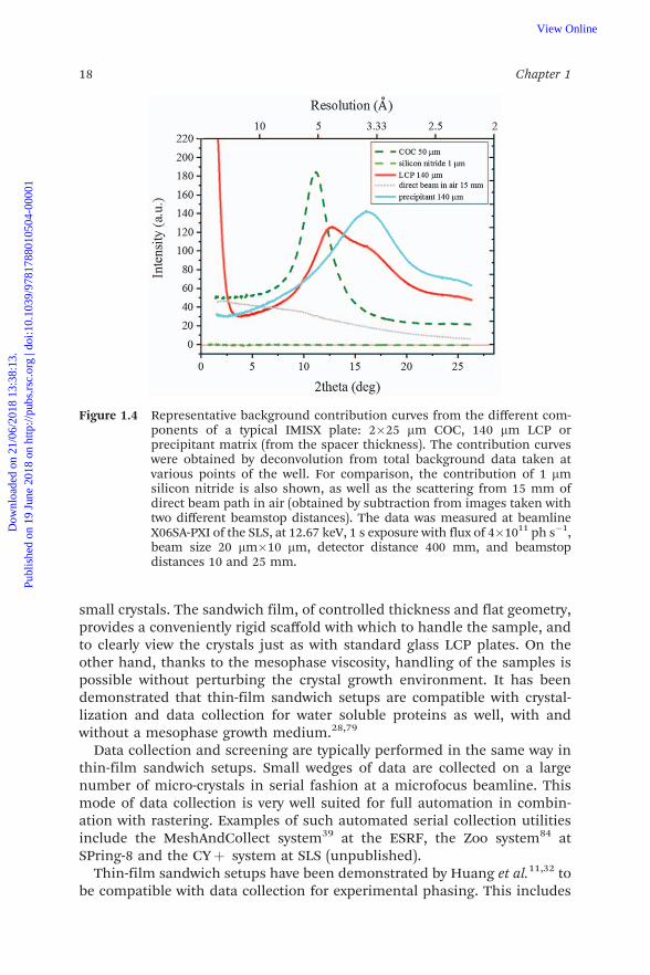
Careful selection of the thin film material is necessary to minimize theabsorption and diffraction background contribution. A material with neg-ligible absorption and background scattering would be ideal. However, inpractice, it is sufficient if the absorption and background scattering of thethin film is low in comparison to the contribution from the crystallizationmedium. In addition, particular care must be taken to minimize the back-ground scattering near the diffraction resolution limit of the crystals, wherethe diffraction signals are weak. This is usually around 2.5–4 Å for mosttargets. Plastic films are often used for their low cost, easy handling and thecommercial availability of films with relatively low thicknesses. Nonetheless,they can have ring-featured background28 and their water-tightness is oftenrelatively low. Reported film variants include 25 mm COC,11 13 mm cyclicolefin polymer (COP),79 8 mm Kapton80 and 3.5 mm Mylar.28 The currentlyavailable commercial setups use 25 mm COC (IMISXt by MiTeGen81) and 40mm plastic film (DiffraXt by Molecular Dimensions82). Other materials suchas silicon nitride membranes, with sub-micrometer to nanometer thick-nesses and low water permeability, have also been used. However, these arefragile, difficult to handle, are more expensive,83 and are used mainly for datacollection purposes. The thickness of the spacer between the two thin films inthe sandwich defines sample thickness. The spacer thickness is therefore amajor parameter in the optimization of background. The spacer thicknessesreported in the literature range from 50 to 140 mm. Commercial setups comewith 140 mm (IMISXt by MiTeGen81) and 100 mm (DiffraXt by MolecularDimensions82) spacers. In the DiffraXt setup by Molecular Dimensions, thespacer is already fixed on the base film for ease of handling. Thinner spacersare commercially available. However, issues of preferential orientation ofcrystals, influence on the crystallization conditions and difficulty of handlinghave been reported with thinner spacers.28 Figure 1.4 shows representativebackground curves corresponding to the contribution of each of the com-ponents of the thin-film sandwich in the current IMISXt setup by MiTeGen.The COC film has maximum scatter at intermediate resolution (4–6 Å), whileat higher scattering angles the matrix (LCP and precipitant solution) gives themost significant contribution because of the spacer thickness. Thin siliconnitride has virtually zero background, which becomes beneficial compared toplastic films in cases where the spacer used is relatively thin. Dedicatedholders for securing the sample on standard magnetic goniometers havebeen developed by several groups28,79 and some are commercially available.
Thin-film methods were developed originally for in meso or LCP crystal-lization, since the high viscosity of the mesophase in which crystallizationtakes place makes it difficult to harvest crystals, and the method often yields
Practical Approaches for In Situ X-ray Crystallography 17
Dow
nloa
ded
on 2
1/06
/201
8 13
:38:
13.
Publ
ishe
d on
19
June
201
8 on
http
://pu
bs.r
sc.o
rg |
doi:1
0.10
39/9
7817
8801
0504
-000
01View Online
small crystals. The sandwich film, of controlled thickness and flat geometry,provides a conveniently rigid scaffold with which to handle the sample, andto clearly view the crystals just as with standard glass LCP plates. On theother hand, thanks to the mesophase viscosity, handling of the samples ispossible without perturbing the crystal growth environment. It has beendemonstrated that thin-film sandwich setups are compatible with crystal-lization and data collection for water soluble proteins as well, with andwithout a mesophase growth medium.28,79
Data collection and screening are typically performed in the same way inthin-film sandwich setups. Small wedges of data are collected on a largenumber of micro-crystals in serial fashion at a microfocus beamline. Thismode of data collection is very well suited for full automation in combin-ation with rastering. Examples of such automated serial collection utilitiesinclude the MeshAndCollect system39 at the ESRF, the Zoo system84 atSPring-8 and the CYþ system at SLS (unpublished).
Thin-film sandwich setups have been demonstrated by Huang et al.11,32 tobe compatible with data collection for experimental phasing. This includes
Figure 1.4 Representative background contribution curves from the different com-ponents of a typical IMISX plate: 2�25 mm COC, 140 mm LCP orprecipitant matrix (from the spacer thickness). The contribution curveswere obtained by deconvolution from total background data taken atvarious points of the well. For comparison, the contribution of 1 mmsilicon nitride is also shown, as well as the scattering from 15 mm ofdirect beam path in air (obtained by subtraction from images taken withtwo different beamstop distances). The data was measured at beamlineX06SA-PXI of the SLS, at 12.67 keV, 1 s exposure with flux of 4�1011 ph s�1,beam size 20 mm�10 mm, detector distance 400 mm, and beamstopdistances 10 and 25 mm.
18 Chapter 1
Dow
nloa
ded
on 2
1/06
/201
8 13
:38:
13.
Publ
ishe
d on
19
June
201
8 on
http
://pu
bs.r
sc.o
rg |
doi:1
0.10
39/9
7817
8801
0504
-000
01View Online
bromine and native SAD phasing of various proteins. Key to the success ofthe process was the accumulation of enough data to extract weak anomaloussignals. Schubert et al.80 have explored the suitability of the setup for time-resolved dynamic studies at RT, using a dose-dependent study of the pro-gress of radiation damage on a model protein as an example. The number ofcrystals required for a complete data set depends on the conditions (RT orcryo), crystal size, space group and phasing method. For example, in thework of Huang et al., in the case of lysozyme at RT,11 about 100 crystals ofaround 20 mm in size from 2 wells were needed to solve the structure bymolecular replacement, 200 crystals from 4 wells were needed for bromidesingle wavelength anomalous diffraction (SAD) phasing, while 1000 crystalsof from 12 wells were needed for native SAD phasing. Under cryogenicconditions,32 only a handful of crystals were needed in similar circum-stances. For instance, only six 30 mm crystals were required to solve an in-sulin structure by native SAD. For membrane proteins, significantly morecrystals are generally required due to their smaller size, weaker diffractionand enhanced radiation sensitivity. Typically, with a microfocused beam, afew images per crystal can be obtained at RT, and a partial data set undercryogenic conditions, depending on the radiation damage threshold.
1.4.2 Liquid Manipulation Methods
The liquid manipulation methods briefly covered in this section might beconsidered in situ by the absence of manual crystal handing. Post-crystalgrowth, ADE methods are an emerging sample delivery scheme. They comewith a few variants, but all involve the use of acoustic waves of definedfrequency propagating through a liquid suspension to deform the surfaceso as to create droplets of controllable size. Crystals can be trapped inthe droplets, which are either presented directly to the beam, ideally in adrop-on-demand fashion,85 or are deposited on a conveyor belt or tapedrive.86,87,98 Another variant involves trapping the drop in an acousticstanding wave field.88 However, acoustic droplet manipulation can be dif-ficult in the presence of surfactants, as it is often the case for crystallizationof membrane proteins in solution.
Inherited from XFEL sample delivery techniques, injection methods canbe compared to in situ methods, at least when the crystals are not filtered,pressurized or transferred to or mixed with a different matrix after crystalgrowth.89 This corresponds to cases of microcrystals grown in liquid bybatch methods and directly injected in a capillary90 or in a microfluidictrap.91 Electrospinning injection92,93 is another liquid delivery techniquewhere mixing is not required. Crystals grown in LCP can also be injectedsufficiently slowly for synchrotron serial data collection30,94,95 using a high-viscosity injector. Injection delivery methods have been covered by severalprevious reviews,96 to which the interested reader is referred. Manipulationof microcrystals often involves pipetting, which can be considered as rela-tively mild handling compared to standard harvesting.97
Practical Approaches for In Situ X-ray Crystallography 19
Dow
nloa
ded
on 2
1/06
/201
8 13
:38:
13.
Publ
ishe
d on
19
June
201
8 on
http
://pu
bs.r
sc.o
rg |
doi:1
0.10
39/9
7817
8801
0504
-000
01View Online
1.5 Conclusion and OutlookIn this chapter we have covered the wide variety of in situ crystal growth anddiffraction setups available, including SBS-format plates, microfluidics,and thin-film sandwich methods. In situ method development is a dynamicfield, where new approaches, materials and equipment are being introducedby user groups and facilities on a regular basis. All the methods coveredhere will continue to benefit from progress in materials manufacturing,for further optimization of thickness and background properties of platesand films.
The development of synchrotron sources will give access to increasinglyhigher flux densities with the emergence of diffraction limited storage ringsat 4th generation synchrotrons. These include the new MAX IV facility inSweden and the planned upgrades at many 3rd generation sources. The lowemittance of this new type of facility naturally increases the flux density andmakes it easier to obtain stable microfocused beams useful for in situ datacollection. Also on the horizon are ‘pink beam’ beamlines. These providebandwidths of the order of 0.1–1% via multilayer monochromator, in con-trast to silicon (111) crystal monochromators with a bandwidth ofB0.02%.The wider bandwidth results in an increase of flux density but also broadensreflections and increases scattering background, which might lower the SNRof weak reflections and create problems due to reflection overlap when usedwith large unit cell crystals.
Future developments in in situ data collection will aim to optimize SNRfor smaller crystals and to improve experimental phasing possibilities,in particular for thin-film sandwich setups. In situ experimental phasingusing heavy atom derivatives and native lighter anomalous scatterers(sulfur, phosphorous, calcium, etc.) has already been demonstrated. How-ever, measurement of very small anomalous differences still requires largeamounts of data and careful optimization of the SNR, and radiationdamage remains an issue. Improvements in crystallization setups andmaterials, beamline automation and data processing will contribute tomaking serial experimental phasing a more routine data collectionmethod. One of the next avenues to explore will be the use of serial in situdata collection for ligand screening and fragment based drug design. Thistype of high-throughput application will require improved automation ofdata collection and data processing. Finally, serial in situ techniquescall for specific user training to make the new techniques available to all.Towards this end, detailed protocols have been published, includinginstructional videos,11,32 and training workshops take place regularly indifferent facilities.
AcknowledgementsWe acknowledge Laura Vera, May Marsh and Chia-Ying Huang for stimu-lating discussions.
20 Chapter 1
Dow
nloa
ded
on 2
1/06
/201
8 13
:38:
13.
Publ
ishe
d on
19
June
201
8 on
http
://pu
bs.r
sc.o
rg |
doi:1
0.10
39/9
7817
8801
0504
-000
01View Online
References1. U. Zander, G. Hoffmann, I. Cornaciu, J.-P. Marquette, G. Papp, C. Landret,
G. Seroul, J. Sinoir, M. Rower, F. Felisaz, S. Rodriguez-Puente, V. Mariaule,P. Murphy, M. Mathieu, F. Cipriani and J. A. Marquez, Acta Crystallogr.,Sect. D: Struct. Biol., 2016, 72, 454–466.
2. P. Roedig, I. Vartiainen, R. Duman, S. Panneerselvam, N. Stube,O. Lorbeer, M. Warmer, G. Sutton, D. I. Stuart, E. Weckert, C. David,A. Wagner and A. Meents, Sci. Rep., 2015, 5, 10451.
3. C. Mueller, A. Marx, S. W. Epp, Y. Zhong, A. Kuo, A. R. Balo, J. Soman,F. Schotte, H. T. Lemke, R. L. Owen, E. F. Pai, A. R. Pearson, J. S. Olson,P. A. Anfinrud, O. P. Ernst and R. J. Dwayne Miller, Struct. Dyn., 2015,2, 054302.
4. J. M. Garciaruiz, A. Moreno, C. Viedma and M. Coll, Mater. Res. Bull.,1993, 28, 541–546.
5. F. J. Lopez-Jaramillo, J. M. Garcıa-Ruiz, J. A. Gavira and F. Otalora,J. Appl. Crystallogr., 2001, 34, 365–370.
6. L. Jacquamet, J. Ohana, J. Joly, F. Borel, M. Pirocchi, P. Charrault,A. Bertoni, P. Israel-Gouy, P. Carpentier, F. Kozielski, D. Blot andJ.-L. Ferrer, Structure, 2004, 12, 1219–1225.
7. C. Porta, A. Kotecha, A. Burman, T. Jackson, J. Ren, S. Loureiro, I. M. Jones,E. E. Fry, D. I. Stuart and B. Charleston, PLoS Pathog., 2013, 9, e1003255.
8. J. A. Newman, S. Zhang, S. Z. Sullivan, X. Y. Dow, M. Becker, M. J. Sheedlo,S. Stepanov, M. S. Carlsen, R. M. Everly, C. Das, R. F. Fischetti andG. J. Simpson, J. Synchrotron Radiat., 2016, 23, 959–965.
9. R. Bingel-Erlenmeyer, V. Olieric, J. P. A. Grimshaw, J. Gabadinho, X. Wang,S. G. Ebner, A. Isenegger, R. Schneider, J. Schneider, W. Glettig,C. Pradervand, E. H. Panepucci, T. Tomizaki, M. Wang and C. Schulze-Briese, Cryst. Growth Des., 2011, 11, 916–923.
10. M. Gelin, V. Delfosse, F. Allemand, F. Hoh, Y. Sallaz-Damaz, M. Pirocchi,W. Bourguet, J. L. Ferrer, G. Labesse and J. F. C. C. Guichou, ActaCrystallogr., Sect. D: Biol. Crystallogr., 2015, 71, 1777–1787.
11. C. Y. Huang, V. Olieric, P. Ma, E. Panepucci, K. Diederichs, M. Wang andM. Caffrey, Acta Crystallogr., Sect. D: Biol. Crystallogr., 2015, 71, 1238–1256.
12. J. L. Smith, R. F. Fischetti and M. Yamamoto, Curr. Opin. Struct. Biol.,2012, 22, 602–612.
13. K. Diederichs and M. Wang, in Protein Crystallography: Methods andProtocols, 2017, ch. 10.
14. I. Schlichting, IUCrJ, 2015, 2, 246–255.15. J. M. Martin-Garcia, C. E. Conrad, J. Coe, S. Roy-Chowdhury and
P. Fromme, Arch. Biochem. Biophys., 2016, 602, 32–47.16. C. Abergel, Acta Crystallogr., Sect. D: Biol. Crystallogr., 2004, 60, 1413–1416.17. A. Douangamath, P. Aller, P. Lukacik, J. Sanchez-Weatherby, I. Moraes
and J. Brandao-Neto, Acta Crystallogr., Sect. D: Biol. Crystallogr., 2013, 69,920–923.
Practical Approaches for In Situ X-ray Crystallography 21
Dow
nloa
ded
on 2
1/06
/201
8 13
:38:
13.
Publ
ishe
d on
19
June
201
8 on
http
://pu
bs.r
sc.o
rg |
doi:1
0.10
39/9
7817
8801
0504
-000
01View Online
18. E. F. Garman, Acta Crystallogr., Sect. D: Biol. Crystallogr., 2010, 66,339–351.
19. R. J. Southworth-Davies, M. A. Medina, I. Carmichael and E. F. Garman,Structure, 2007, 15, 1531–1541.
20. R. Henderson, Proc. R. Soc. B, 1990, 241, 6–8.21. R. L. Owen, E. Rudino-Pinera and E. F. Garman, Proc. Natl. Acad. Sci.
U. S. A., 2006, 103, 4912–4917.22. T. Weinert, V. Olieric, S. Waltersperger, E. Panepucci, L. Chen, H. Zhang,
D. Zhou, J. Rose, A. Ebihara, S. Kuramitsu, D. Li, N. Howe, G. Schnapp,A. Pautsch, K. Bargsten, A. E. Prota, P. Surana, J. Kottur, D. T. Nair,F. Basilico, V. Cecatiello, S. Pasqualato, A. Boland, O. Weichenrieder,B. C. Wang, M. O. Steinmetz, M. Caffrey and M. Wang, Nat. Methods,2015, 12, 131–133.
23. J. M. Holton, J. Synchrotron Radiat., 2009, 16, 133–142.24. D. Axford, R. L. Owen, J. Aishima, J. Foadi, A. W. Morgan, J. I. Robinson,
J. E. Nettleship, R. J. Owens, I. Moraes, E. E. Fry, J. M. Grimes, K. Harlos,A. Kotecha, J. S. Ren, G. Sutton, T. S. Walter, D. I. Stuart and G. Evans,Acta Crystallogr., Sect. D: Struct. Biol., 2012, 68, 592–600.
25. L. E. Zipper, X. Aristide, D. P. Bishop, I. Joshi, J. Kharzeev, K. B. Patel,B. M. Santiago, K. Joshi, K. Dorsinvil, R. M. Sweet and A. S. Soares, ActaCrystallogr., Sect. F: Struct. Biol. Commun., 2014, 70, 1707–1713.
26. V. Cherezov and M. Caffrey, J. Appl. Crystallogr., 2006, 39, 604–606.27. K. Michalska, K. Tan, C. Chang, H. Li, C. Hatzos-Skintges, M. Molitsky,
R. Alkire and A. Joachimiak, J. Synchrotron Radiat., 2015, 22,1386–1395.
28. J. Broecker, V. Klingel, W.-L. Ou, A. R. Balo, D. J. Kissick, C. M. Ogata,A. Kuo and O. P. Ernst, Cryst. Growth Des., 2016, 16, 6318–6326.
29. U. Mueller, N. Darowski, M. R. Fuchs, R. Forster, M. Hellmig,K. S. Paithankar, S. Puhringer, M. Steffien, G. Zocher and M. S. Weiss,J. Synchrotron Radiat., 2012, 19, 442–449.
30. P. Nogly, D. James, D. Wang, T. A. White, N. Zatsepin, A. Shilova,G. Nelson, H. Liu, L. Johansson, M. Heymann, K. Jaeger, M. Metz,C. Wickstrand, W. Wu, P. Båth, P. Berntsen, D. Oberthuer, V. Panneels,V. Cherezov, H. N. Chapman, G. Schertler, R. Neutze, J. Spence, I. Moraes,M. Burghammer, J. Standfuss and U. Weierstall, IUCrJ, 2015, 2, 1–9.
31. Y. Yamada, M. Hiraki, N. Matsugaki, R. Kato and T. Senda, Proceedingsof the 12th International Conference on Synchrotron Radiation Instru-mentation – SRI2015, New York, USA, 2015.
32. C.-Y. Huang, V. Olieric, P. Ma, N. Howe, L. Vogeley, X. Liu,R. Warshamanage, T. Weinert, E. Panepucci, B. Kobilka, K. Diederichs,M. Wang and M. Caffrey, Acta Crystallogr., Sect. D: Struct. Biol., 2016, 72,93–112.
33. K. Hirata, Y. Kawano, G. Ueno, K. Hashimoto, H. Murakami, K. Hasegawa,T. Hikima, T. Kumasaka and M. Yamamoto, J. Phys.: Conf. Ser., 2013,425, 012002.
22 Chapter 1
Dow
nloa
ded
on 2
1/06
/201
8 13
:38:
13.
Publ
ishe
d on
19
June
201
8 on
http
://pu
bs.r
sc.o
rg |
doi:1
0.10
39/9
7817
8801
0504
-000
01View Online
34. J. A. Wojdyla, E. Panepucci, I. Martiel, S. Ebner, C.-Y. Huang, M. Caffrey,O. Bunk and M. Wang, J. Appl. Crystallogr., 2016, 49, 944–952.
35. L. Jacquamet, J. Ohana, J. Joly, P. Legrand, R. Kahn, F. Borel, M. Pirocchi,P. Charrault, P. Carpentier and J. L. Ferrer, Acta Crystallogr., Sect. D: Biol.Crystallogr., 2004, 60, 888–894.
36. M. Roth, P. Carpentier, O. Kaıkati, J. Joly, P. Charrault, M. Pirocchi,R. Kahn, E. Fanchon, L. Jacquamet, F. Borel, A. Bertoni, P. Israel-Gouyand J.-L. Ferrer, Acta Crystallogr., Sect. D: Biol. Crystallogr., 2002, 58,805–814.
37. D. Nurizzo, M. W. Bowler, H. Caserotto, F. Dobias, T. Giraud, J. Surr,N. Guichard, G. Papp, M. Guijarro, C. Mueller-Dieckmann, D. Flot,S. McSweeney, F. Cipriani, P. Theveneau and G. A. Leonard, Acta Crys-tallogr., Sect. D: Struct. Biol., 2016, 72, 966–975.
38. V. Cherezov, M. A. Hanson, M. T. Griffith, M. C. Hilgart, R. Sanishvili,V. Nagarajan, S. Stepanov, R. F. Fischetti, P. Kuhn and R. C. Stevens,J. R .Soc., Interface, 2009, 6(Suppl 5), S587–S597.
39. U. Zander, G. Bourenkov, A. N. Popov, D. de Sanctis, O. Svensson,A. A. McCarthy, E. Round, V. Gordeliy, C. Mueller-Dieckmann andG. A. Leonard, Acta Crystallogr., Sect. D: Biol. Crystallogr., 2015, 71, 2328–2343.
40. G. Assmann, W. Brehm and K. Diederichs, J. Appl. Crystallogr., 2016, 49,1021–1028.
41. R. Giordano, R. M. Leal, G. P. Bourenkov, S. McSweeney and A. N. Popov,Acta Crystallogr., Sect. D: Biol. Crystallogr., 2012, 68, 649–658.
42. J. Foadi, P. Aller, Y. Alguel, A. Cameron, D. Axford, R. L. Owen,W. Armour, D. G. Waterman, S. Iwata and G. Evans, Acta Crystallogr.,Sect. D: Biol. Crystallogr., 2013, 69, 1617–1632.
43. P. Aller, J. Sanchez-Weatherby, J. Foadi, G. Winter, C. M. C. Lobley,D. Axford, A. W. Ashton, D. Bellini, J. Brandao-Neto, S. Culurgioni,A. Douangamath, R. Duman, G. Evans, S. Fisher, R. Flaig, D. R. Hall,P. Lukacik, M. Mazzorana, K. E. McAuley, V. Mykhaylyk, R. L. Owen,N. G. Paterson, P. Romano, J. Sandy, T. Sorensen, F. von Delft,A. Wagner, A. Warren, M. Williams, D. I. Stuart and M. A. Walsh,Methods Mol. Biol., 2015, 1261, 233–253.
44. A. E. Bruno, A. S. Soares, R. L. Owen and E. H. Snell, J. Appl. Crystallogr.,2016, 49, 2082–2090.
45. A. le Maire, M. Gelin, S. Pochet, F. Hoh, M. Pirocchi, J. F. Guichou,J. L. Ferrer and G. Labesse, Acta Crystallogr., Sect. D: Biol. Crystallogr.,2011, 67, 747–755.
46. D. Axford, J. Foadi, N.-J. Hu, H. G. Choudhury, S. Iwata, K. Beis, G. Evansand Y. Alguel, Acta Crystallogr., Sect. D: Biol. Crystallogr., 2015, 71, 1228–1237.
47. A. Burkhardt, A. Wagner, M. Warmer, R. Reimer, H. Hohenberg, J. Ren,E. E. Fry, D. I. Stuart and A. Meents, Acta Crystallogr., Sect. D: Biol.Crystallogr., 2013, 69, 308–312.
Practical Approaches for In Situ X-ray Crystallography 23
Dow
nloa
ded
on 2
1/06
/201
8 13
:38:
13.
Publ
ishe
d on
19
June
201
8 on
http
://pu
bs.r
sc.o
rg |
doi:1
0.10
39/9
7817
8801
0504
-000
01View Online
48. E. Teplitsky, K. Joshi, D. L. Ericson, A. Scalia, J. D. Mullen, R. M. Sweetand A. S. Soares, J. Struct. Biol., 2015, 191, 49–58.
49. F. Pinker, M. Brun, P. Morin, A.-L. Deman, J.-F. Chateaux, V. Olieric,C. Stirnimann, B. Lorber, N. Terrier, R. Ferrigno and C. Sauter, Cryst.Growth Des., 2013, 13, 3333–3340.
50. L. Jacquamet, J. Joly, A. Bertoni, P. Charrault, M. Pirocchi, X. Vernede,F. Bouis, F. Borel, J. P. Perin, T. Denis, J. L. Rechatin and J. L. Ferrer,J. Synchrotron Radiat., 2009, 16, 14–21.
51. V. Grama, D. Axford, G. Duller, M. Burt and R. L. Owen, I24 Endstationupgrade - overview and engineering design, MEDSI 2014 ConferenceMelbourne, Australia, 2014.
52. D. Hargreaves, J. Appl. Crystallogr., 2012, 45, 138–140.53. J. M. Holton, S. Classen, K. A. Frankel and J. A. Tainer, FEBS J., 2014, 281,
4046–4060.54. MiTeGen, In-Situ-01tCrystallization Plate, http://www.mitegen.com/
products/plates/insitu1/brochure.pdf (accessed on 03.02.2017).55. F. Cipriani, M. Rower, C. Landret, U. Zander, F. Felisaz and J. A. Marquez,
Acta Crystallogr., Sect. D: Biol. Crystallogr., 2012, 68, 1393–1399.56. VMXi beamline at Diamond Light Source, http://www.diamond.ac.uk/
Beamlines/Mx/VMXi.html (accessed on 19.02.2017).57. G. Kisselman, W. Qiu, V. Romanov, C. M. Thompson, R. Lam,
K. P. Battaile, E. F. Pai and N. Y. Chirgadze, Acta Crystallogr., Sect. D: Biol.Crystallogr., 2011, 67, 533–539.
58. M. Heymann, A. Opathalage, J. L. Wierman, S. Akella, D. M. E. Szebenyi,S. M. Gruner and S. Fraden, IUCrJ, 2014, 1, 349–360.
59. K. Dhouib, C. Khan Malek, W. Pfleging, B. Gauthier-Manuel, R. Duffait,G. Thuillier, R. Ferrigno, L. Jacquamet, J. Ohana, J.-L. Ferrer,A. Theobald-Dietrich, R. Giege, B. Lorber and C. Sauter, Lab Chip, 2009,9, 1412–1421.
60. E. L. Baxter, L. Aguila, R. Alonso-Mori, C. O. Barnes, C. A. Bonagura,W. Brehmer, A. T. Brunger, G. Calero, T. T. Caradoc-Davies, R. Chatterjee,W. F. Degrado, J. S. Fraser, M. Ibrahim, J. Kern, B. K. Kobilka, A. C. Kruse,K. M. Larsson, H. T. Lemke, A. Y. Lyubimov, A. Manglik, S. E. McPhillips,E. Norgren, S. S. Pang, S. M. Soltis, J. Song, J. Thomaston, Y. Tsai,W. I. Weis, R. A. Woldeyes, V. Yachandra, J. Yano, A. Zouni andA. E. Cohen, Acta Crystallogr., Sect. D: Struct. Biol., 2016, 72, 1–10.
61. XChip information, http://www.mitegen.com/product/x-chip/ (accessedon 18.03.2018).
62. A. E. Cohen, S. M. Soltis, A. Gonzalez, L. Aguila, R. Alonso-Mori,C. O. Barnes, E. L. Baxter, W. Brehmer, A. S. Brewster, A. T. Brunger,G. Calero, J. F. Chang, M. Chollet, P. Ehrensberger, T. L. Eriksson,Y. Feng, J. Hattne, B. Hedman, M. Hollenbeck, J. M. Holton, S. Keable,B. K. Kobilka, E. G. Kovaleva, A. C. Kruse, H. T. Lemke, G. Lin,A. Y. Lyubimov, A. Manglik, Mathews II, S. E. McPhillips, S. Nelson,J. W. Peters, N. K. Sauter, C. A. Smith, J. Song, H. P. Stevenson, Y. Tsai,M. Uervirojnangkoorn, V. Vinetsky, S. Wakatsuki, W. I. Weis,
24 Chapter 1
Dow
nloa
ded
on 2
1/06
/201
8 13
:38:
13.
Publ
ishe
d on
19
June
201
8 on
http
://pu
bs.r
sc.o
rg |
doi:1
0.10
39/9
7817
8801
0504
-000
01View Online

O. A. Zadvornyy, O. B. Zeldin, D. Zhu and K. O. Hodgson, Proc. Natl.Acad. Sci. U. S. A., 2014, 111, 17122–17127.
63. X. Yin, A. Scalia, L. Leroy, C. M. Cuttitta, G. M. Polizzo, D. L. Ericson,C. G. Roessler, O. Campos, M. Y. Ma, R. Agarwal, R. Jackimowicz,M. Allaire, A. M. Orville, R. M. Sweet and A. S. Soares, Acta Crystallogr.,Sect. D: Biol. Crystallogr., 2014, 70, 1177–1189.
64. M. A. Berger, J. H. Decker and Mathews II, J. Appl. Crystallogr., 2010, 43,1513–1518.
65. S. Sui, Y. Wang, K. W. Kolewe, V. Srajer, R. Henning, J. D. Schiffman,C. Dimitrakopoulos and S. L. Perry, Lab Chip, 2016, 16, 3082–3096.
66. J. E. Lee, M. L. Fusco and E. O. Saphire, Nat. Protoc., 2009, 4,592–604.
67. I. Russo Krauss, A. Merlino, A. Vergara and F. Sica, Int. J. Mol. Sci., 2013,14, 11643–11691.
68. S. Guha, S. L. Perry, A. S. Pawate and P. J. Kenis, Sens. Actuators, B, 2012,174, 1–9.
69. S. L. Perry, S. Guha, A. S. Pawate, R. Henning, I. Kosheleva, V. Srajer,P. J. Kenis and Z. Ren, J. Appl. Crystallogr., 2014, 47, 1975–1982.
70. D. S. Khvostichenko, J. M. Schieferstein, A. S. Pawate, P. D. Laible andP. J. A. Kenis, Cryst. Growth Des., 2014, 14, 4886–4890.
71. J. D. Ng, P. J. Clark, R. C. Stevens and P. Kuhn, Acta Crystallogr., Sect. D:Biol. Crystallogr., 2008, 64, 189–197.
72. CrystalSlide information, http://www.mitegen.com/products/plates/CrystalSlide_UserGuide_E.pdf (accessed on 16.02.2017).
73. CrystalHarp information, https://www.moleculardimensions.com/applications/upload/Crystalharp%20flyer_UK.pdf (accessed on 16.02.2017).
74. B. Zheng, J. D. Tice, L. S. Roach and R. F. Ismagilov, Angew. Chem., Int.Ed. Engl., 2004, 43, 2508–2511.
75. C. J. Gerdts, M. Elliott, S. Lovell, M. B. Mixon, A. J. Napuli, B. L. Staker,P. Nollert and L. Stewart, Acta Crystallogr., Sect. D: Biol. Crystallogr., 2008,64, 1116–1122.
76. J. Christensen, C. J. Gerdts, M. C. Clifton and L. Stewart, Acta Crystal-logr., Sect. F: Struct. Biol. Cryst. Commun., 2011, 67, 1022–1026.
77. M. K. Yadav, C. J. Gerdts, R. Sanishvili, W. W. Smith, L. S. Roach,R. F. Ismagilov, P. Kuhn and R. C. Stevens, J. Appl. Crystallogr., 2005, 38,900–905.
78. S. V. Akella, A. Mowitz, M. Heymann and S. Fraden, Cryst. Growth Des.,2014, 14, 4487–4509.
79. D. Axford, P. Aller, J. Sanchez-Weatherby and J. Sandy, Acta Crystallogr.,Sect. F: Struct. Biol. Cryst. Commun., 2016, 72, 313–319.
80. R. Schubert, S. Kapis, Y. Gicquel, G. Bourenkov, T. R. Schneider,M. Heymann, C. Betzel and M. Perbandt, IUCrJ, 2016, 3, 393–401.
81. MiTeGen webpage, http://www.mitegen.com/lcp/imisx/ (accessed on17.02.2017).
82. A. Savill, personal communication.83. V. Cherezov and M. Caffrey, Faraday Discuss., 2007, 136, 195.
Practical Approaches for In Situ X-ray Crystallography 25
Dow
nloa
ded
on 2
1/06
/201
8 13
:38:
13.
Publ
ishe
d on
19
June
201
8 on
http
://pu
bs.r
sc.o
rg |
doi:1
0.10
39/9
7817
8801
0504
-000
01View Online
84. K. Hirata, Towards Automatic Data Collection Pipeline for MembraneProtein Structure Analyses at Beamline BL32XU, Synchrotron Radiationand Instrumentation 2015 conference, 2015.
85. C. G. Roessler, R. Agarwal, M. Allaire, R. Alonso-Mori, B. Andi,J. F. R. Bachega, M. Bommer, A. S. Brewster, M. C. Browne, R. Chatterjee,E. Cho, A. E. Cohen, M. Cowan, S. Datwani, V. L. Davidson, J. Defever,B. Eaton, R. Ellson, Y. Feng, L. P. Ghislain, J. M. Glownia, G. Han,J. Hattne, J. Hellmich, A. Heroux, M. Ibrahim, J. Kern, A. Kuczewski,H. T. Lemke, P. Liu, L. Majlof, W. M. McClintock, S. Myers, S. Nelsen,J. Olechno, A. M. Orville, N. K. Sauter, A. S. Soares, S. M. Soltis, H. Song,R. G. Stearns, R. Tran, Y. Tsai, M. Uervirojnangkoorn, C. M. Wilmot,V. Yachandra, J. Yano, E. T. Yukl, D. Zhu and A. Zouni, Structure, 2016,631–640.
86. C. G. Roessler, A. Kuczewski, R. Stearns, R. Ellson, J. Olechno,A. M. Orville, M. Allaire, A. S. Soares and A. Heroux, J. SynchrotronRadiat., 2013, 20, 805–808.
87. F. D. Fuller, S. Gul, R. Chatterjee, E. S. Burgie, I. D. Young, H. Lebrette,V. Srinivas, A. S. Brewster, T. Michels-Clark, J. A. Clinger, B. Andi,M. Ibrahim, E. Pastor, C. de Lichtenberg, R. Hussein, C. J. Pollock,M. Zhang, C. A. Stan, T. Kroll, T. Fransson, C. Weninger, M. Kubin,P. Aller, L. Lassalle, P. Brauer, M. D. Miller, M. Amin, S. Koroidov,C. G. Roessler, M. Allaire, R. G. Sierra, P. T. Docker, J. M. Glownia,S. Nelson, J. E. Koglin, D. Zhu, M. Chollet, S. Song, H. Lemke, M. Liang,D. Sokaras, R. Alonso-Mori, A. Zouni, J. Messinger, U. Bergmann,A. K. Boal, J. M. Bollinger Jr., C. Krebs, M. Hogbom, G. N. Phillips Jr.,R. D. Vierstra, N. K. Sauter, A. M. Orville, J. Kern, V. K. Yachandra andJ. Yano, Nat. Methods, 2017, 14, 443–449.
88. S. Tsujino and T. Tomizaki, Sci. Rep., 2016, 6, 25558.89. H. P. Stevenson, D. P. DePonte, A. M. Makhov, J. F. Conway, O. B. Zeldin,
S. Boutet, G. Calero and A. E. Cohen, Philos. Trans. R. Soc. London, 2014,369, 20130322.
90. F. Stellato, D. Oberthur, M. Liang, R. Bean, C. Gati, O. Yefanov, A. Barty,A. Burkhardt, P. Fischer, L. Galli, R. A. Kirian, J. Meyer, S. Panneerselvam,C. H. Yoon, F. Chervinskii, E. Speller, T. A. White, C. Betzel, A. Meentsand H. N. Chapman, IUCrJ, 2014, 1, 204–212.
91. A. Y. Lyubimov, T. D. Murray, A. Koehl, I. E. Araci, M. Uervirojnangkoorn,O. B. Zeldin, A. E. Cohen, S. M. Soltis, E. L. Baxter, A. S. Brewster,N. K. Sauter, A. T. Brunger and J. M. Berger, Acta Crystallogr., Sect. D: Biol.Crystallogr., 2015, 71, 928–940.
92. R. G. Sierra, C. Gati, H. Laksmono, E. H. Dao, S. Gul, F. Fuller, J. Kern,R. Chatterjee, M. Ibrahim, A. S. Brewster, I. D. Young, T. Michels-Clark,A. Aquila, M. Liang, M. S. Hunter, J. E. Koglin, S. Boutet, E. A. Junco,B. Hayes, M. J. Bogan, C. Y. Hampton, E. V. Puglisi, N. K. Sauter,C. A. Stan, A. Zouni, J. Yano, V. K. Yachandra, S. M. Soltis, J. D. Puglisiand H. DeMirci, Nat. Methods, 2015, 13, 59–62.
26 Chapter 1
Dow
nloa
ded
on 2
1/06
/201
8 13
:38:
13.
Publ
ishe
d on
19
June
201
8 on
http
://pu
bs.r
sc.o
rg |
doi:1
0.10
39/9
7817
8801
0504
-000
01View Online
93. R. G. Sierra, H. Laksmono, J. Kern, R. Tran, J. Hattne, R. Alonso-Mori,B. Lassalle-Kaiser, C. Glockner, J. Hellmich, D. W. Schafer, N. Echols,R. J. Gildea, R. W. Grosse-Kunstleve, J. Sellberg, T. A. McQueen, A. R. Fry,M. M. Messerschmidt, A. Miahnahri, M. M. Seibert, C. Y. Hampton,D. Starodub, N. D. Loh, D. Sokaras, T.-C. Weng, P. H. Zwart, P. Glatzel,D. Milathianaki, W. E. White, P. D. Adams, G. J. Williams, S. Boutet,A. Zouni, J. Messinger, N. K. Sauter, U. Bergmann, J. Yano, V. K. Yachandraand M. J. Bogan, Acta Crystallogr., Sect. D: Biol. Crystallogr., 2012, 68, 1584–1587.
94. P. Nogly, V. Panneels, G. Nelson, C. Gati, T. Kimura, C. Milne,D. Milathianaki, M. Kubo, W. Wu, C. Conrad, J. Coe, R. Bean, Y. Zhao,P. Båth, R. Dods, R. Harimoorthy, K. R. Beyerlein, J. Rheinberger, D. James,D. DePonte, C. Li, L. Sala, G. J. Williams, M. S. Hunter, J. E. Koglin,P. Berntsen, E. Nango, S. Iwata, H. N. Chapman, P. Fromme, M. Frank,R. Abela, S. Boutet, A. Barty, T. A. White, U. Weierstall, J. Spence, R. Neutze,G. Schertler and J. Standfuss, Nat. Commun., 2016, 7, 12314.
95. S. Botha, K. Nass, T. R. Barends, W. Kabsch, B. Latz, F. Dworkowski,L. Foucar, E. Panepucci, M. Wang, R. L. Shoeman, I. Schlichting andR. B. Doak, Acta Crystallogr., Sect. D: Biol. Crystallogr., 2015, 71, 387–397.
96. U. Weierstall, Philos. Trans. R. Soc. London, 2014, 369, 20130337.97. M. Boudes, D. Garriga, A. Fryga, T. Caradoc-Davies and F. Coulibaly, Acta
Crystallogr., D: Struct. Biol., 2016, 72, 576–585.98. K. R. Beyerlein, D. Dierksmeyer, V. Mariani, M. Kuhn, I. Sarrou,
A. Ottaviano, S. Awel, J. Knoska, S. Fuglerud, O. Jonsson, S. Stern, M.O. Wiedorn, O. Yefanov, L. Adriano, R. Bean, A. Burkhardt, P. Fischer,M. Heymann, D. A. Horke, K. E. J. Jungnickel, E. Kovaleva, O. Lorbeer,M. Metz, J. Meyer, A. Morgan, K. Pande, S. Panneerselvam, C. Seuring,A. Tolstikova, J. Lieske, S. Aplin, M. Roessle, T. A. White, H. N. Chapman,A. Meents and D. Oberthuer, IUCrJ, 2017, 4, 769–777.
Practical Approaches for In Situ X-ray Crystallography 27
Dow
nloa
ded
on 2
1/06
/201
8 13
:38:
13.
Publ
ishe
d on
19
June
201
8 on
http
://pu
bs.r
sc.o
rg |
doi:1
0.10
39/9
7817
8801
0504
-000
01View Online