chapter 10 components and connectors - catalysis
TRANSCRIPT
Chapter 10 Components and
Connectors
Many software managers, harried by budgets and delays, envy hardware designers. Todesign a steam engine, the engineers did not start by designing screws from scratch. Elec-tronic systems are built by plugging together chips, boards, or boxes that are widelyinteroperable. A well-chosen set of components can have many possible configurations:many end products that can be made quickly and reliably.
Over the past few years, the same thing has begun to happen in software. Word proces-sors can talk to spreadsheets, and graphs to databases. Standards such as COM andCORBA allow you to plug together components in different languages and platforms. Jav-aBeans, or any similar protocol, allows separately designed objects to find out more abouteach other’s capabilities before negotiating a collaboration. Visual building tools help youplug components together pictorially.
Large-grained components are becoming a practical part of an enterprise componentstrategy. These components interact with one another as much as their smaller cousins do,and they must be analyzed and designed so that they interoperate as expected.
This chapter explains how to meet requirements using component-based designs andhow to design components that work well together. After introducing component con-cepts, discussing pluggable parts, and describing how components have evolved over theyears, we look briefly at three component standards: JavaBeans, COM+, and CORBA.
Rather than limit ourselves to a specific component technology, we then introduce theport-connector model of component architectures. We discuss a typical example of suchan architecture and show how to specify and design with components in this architecture.Then we show how even ad hoc and heterogenous component systems are amenable tosystematic development in Catalysis.
10.1 Overview of Component-Based Development
By itself, the use of object-oriented programming is not enough to get stupendousimprovements in software delivery times, development costs, and quality. Some people
383
384 PART IV IMPLEMENTATION BY ASSEMBLY
wonder why, having bought a C++ compiler, they’re not seeing all the glorious benefitsthey’ve heard of.1 But it doesn’t work that way. The greatest benefits depend on goodmanagement of the software development process. The bag of techniques, languages,methods, and tools lumped under the “object-oriented” heading is an enabling technology:It makes it easier to achieve fast, cheap, robust development, but only if you use it prop-erly.
If you want to achieve significant improvements in software productivity, one of themost important shifts is to stop writing applications from scratch every time you embarkon a new project. Instead, you should build by using software components that alreadyexist. The building blocks that you use for software development should not be limited tothose offered by the programming language but should also include larger-grained, encap-sulated units.
Over the past five years or so, we have seen this change happening. Many applicationsare now built on purchased third-party frameworks or by gluing together existing applica-tions. Many programmers have come across Microsoft’s OLE/COM (and before it,DLLs), which provides a way of bolting together entire applications. The OMG’s CORBAprovides similar facilities.
For example, an application that reads stock figures from a newsfeed can be ”wired up”to a spreadsheet; this component does some calculations and passes the results to a data-base, from which a Web server extracts information on demand. Each of these componentsmay be a stand-alone application, perhaps even with its own user interface, but is providedwith a way to interact with other software.
Many development teams think only of gluing together large third-party componentsthat can also work as stand-alones. But the spreadsheet in our example doesn’t need a userinterface: It is used only as a calculating engine within a larger chain. The example couldbe built more efficiently by using a calculating mechanism designed to be used as a com-ponent in a larger design and so lacking all the GUI overhead (perhaps with a suitable GUIas an optional add-on). And the persistence mechanism need not be a part of the spread-sheet itself. It could use a separate data-access component for that; again, it could includea default one.
Most development teams could benefit from thinking more in terms of building theirown components for their application area. This is the key to fast, reliable development: todo it the way hardware designers have been doing it for two centuries and build compo-nents that can be assembled together in many combinations. Most end products—andindeed most components—should be assemblies of smaller components, built either else-where or in-house.
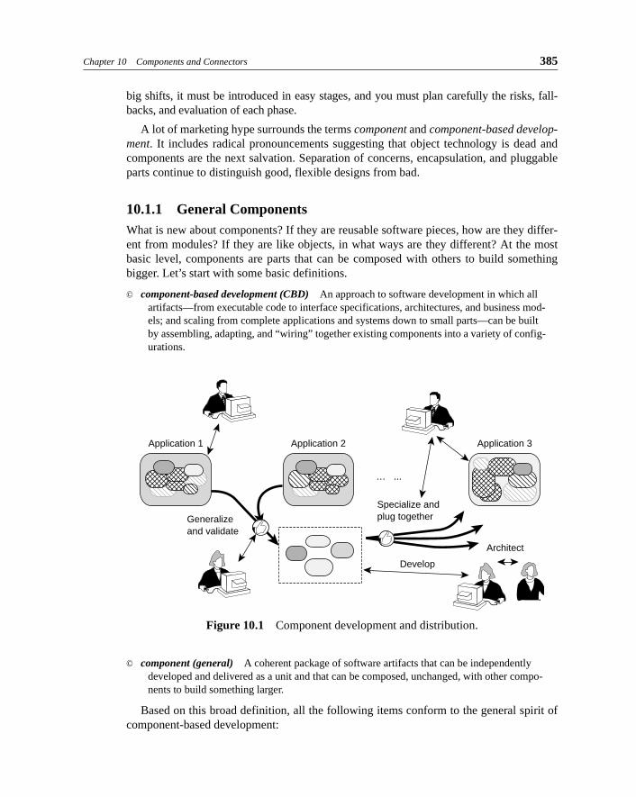
The aim must be to invest in the development of a component library as a capital asset(see Figure 10.1). Like any investment, this one requires money to be spent for a whilebefore any payback is seen. A conventional software development organization requires aconsiderable shift of attitudes and strategy to adopt a component-based approach. Like all
1. And some of them then go around saying, ”It doesn’t work”!
Chapter 10 Components and Connectors 385
big shifts, it must be introduced in easy stages, and you must plan carefully the risks, fall-backs, and evaluation of each phase.
A lot of marketing hype surrounds the terms component and component-based develop-ment. It includes radical pronouncements suggesting that object technology is dead andcomponents are the next salvation. Separation of concerns, encapsulation, and pluggableparts continue to distinguish good, flexible designs from bad.
10.1.1 General ComponentsWhat is new about components? If they are reusable software pieces, how are they differ-ent from modules? If they are like objects, in what ways are they different? At the mostbasic level, components are parts that can be composed with others to build somethingbigger. Let’s start with some basic definitions.
© component-based development (CBD) An approach to software development in which all artifacts—from executable code to interface specifications, architectures, and business mod-els; and scaling from complete applications and systems down to small parts—can be built by assembling, adapting, and “wiring” together existing components into a variety of config-urations.
© component (general) A coherent package of software artifacts that can be independently
developed and delivered as a unit and that can be composed, unchanged, with other compo-nents to build something larger.
Based on this broad definition, all the following items conform to the general spirit ofcomponent-based development:
Figure 10.1 Component development and distribution.
Application 1
Generalizeand validate
Specialize andplug together
Application 2 Application 3
Develop
Architect
… ...
386 PART IV IMPLEMENTATION BY ASSEMBLY
• Dropping a user-interface widget, such as a master-slave pair of list boxes, onto a can-vas and connecting the lists to the appropriate data sources from the problem domain.
• Using the same C++ List template to implement any number of domain classes by spe-cializing the template parameter:
class Order {private: List<LineItem> items;
};
• Using an off-the-shelf calendar package, word processor, and spreadsheet in an assem-blage of several heterogenous components and writing scripts so that these components
together fulfill a particular business need.
• Using a class framework, such as Java’s Swing components, to build the user interfaces
for many applications and to connect those UIs to their domain objects.
• Using a model framework, such as resource allocation, to model problems ranging
from seminar room allocation to scheduling machine time for production lots in a fac-tory.
• Using predefined language constructs in an infinite variety of contexts:for ( ...; ...; ... ) { ... }
A component can include anything that a package can include: executable code, sourcecode, designs, specifications, tests, documentation, and so on. In Chapter 9, Model Frame-works and Template Packages, we show how the idea of composing software based on inter-faces also applies to designs and models, leading to a more general idea of component-basedmodeling: All work is done by adapting and composing existing pieces. To make effectiveuse of implementation components, we should start with componentization of business mod-els and requirements. In this more general sense, a Catalysis package constitutes a compo-nent.
10.1.2 Implementation ComponentsIn this chapter we focus on implementation components: executable code, source code,interface specs, code templates, and the like. In this context, a component is similar to thewell-known software engineering idea of a module, although we have standards in placeand technology infrastructure that makes building distributed component systems a reality.
For one component to replace another, the replacement component need not work thesame internally. However, the replacement component must provide at least the servicesthat the environment expects of the original and must expect no more than the services theenvironment provides the original. The replacement must exhibit the same external behav-ior, including quality requirements such as performance and resource consumption.
© component (in code) A coherent package of software implementation that (a) can be inde-pendently developed and delivered, (b) has explicit and well-specified interfaces for the ser-vices it provides, (c) has explicit and well-specified interfaces for services it expects from
others, and (d) can be composed with other components, perhaps customizing some of their properties, without modifying the components themselves.
Chapter 10 Components and Connectors 387
10.1.2.1 A Unit of Packaging
A component is a “package” of software that includes implementation, with a specificationof interfaces provided and required. The mechanics for this packaging differ. In some com-ponent technologies, such as JavaBeans and COM+, the compiled code for a componentincludes an explicit runtime representation of interfaces; you can programatically inquireabout these interfaces and use the information to establish suitable connections betweencomponents. In other component technologies, the compiled implementation may bestripped of this extra information and reduced to a minimal executable or DLL; in this case,the packaging unit must include separate and explicit descriptions of interfaces provided andrequired. COM (prior to COM+) required a separate and explicit type library containingcomponent interface information to be registered in the shared system registry.
A component package typically includes the following.
• A list of provided interfaces: These are often imported from other packages, containing
only the specs of these interfaces.
• A list of required interfaces: These are often imported from separate packages, just like
the provided interfaces.
• The external specification: This is a specification of external behavior provided and
required, relating all the interfaces in a shared model.
• The executable code: If built according to a suitable and consistent architecture, this
can be coupled to the code of other components via their interfaces.
• The validation code: This is code, for example, that is used to help decide whether a
proposed connection between components is OK.
• The design: This includes all the documents and source code associated with the work
of satisfying the specification; it may be withheld from customers.
Components can also contain modifications to, and extensions of, existing classes. Thisis used often in Smalltalk—in which existing classes and methods can be dynamicallymodified and extended—and also is generally useful for any system that cannot behalted to install software upgrades. The interesting thing in terms of modeling is to pro-vide mechanisms and rules for ensuring that the components do not interfere improperlywith one another after they’re installed in a system.
In some situations it can be useful to further distinguish the specification of a compo-nent, an executable that implements that spec, a particular installation of that executable,and a “running” incarnation of that executable that is available as a server. We will use theterm component loosely to include all these. A tool or metamodel that dealt more fullywith component deployment and management would separate them.
10.1.2.2 A Unit of Independent Delivery
Being independently deliverable means that a component is not delivered partially. Also,it must be specified and delivered in a form that is well separated from any other compo-nents it may interact with when deployed.
388 PART IV IMPLEMENTATION BY ASSEMBLY
10.1.2.3 Explicit Provided and Required Interfaces
The only way one component can interact with another is via a provided interface. Thespecification of a component must explicitly describe all interfaces that a client can expectas well as the interfaces that must be provided by the environment into which the compo-nent is assembled.
For components to be plug-replaceable, it is essential that the component specs be self-contained and symmetrical; it is the only way to be able to design reliably using partswithout knowledge of their implementations. In contrast, a traditional server, in a client-server setting, is one-sided: It provides a set of services, but the services it expects fromothers are not documented explicitly. Object-oriented languages have also focused almostexclusively on services implemented by a class without any explicit description of the ser-vices it expects from other objects.
10.1.2.4 Complete Separation of Interfaces from Implementation
Component software demands a complete separation of interface specifications fromimplementations. The interface specs, rather than the source code, define what a compo-nent will provide and expect when used. In fact, if you are ever forced to use an existingcomponent that does not have an explicitly documented interface, it is usually worth writ-ing a specification of it “as perceived and used”; this document greatly simplifies testingand reduces the time to evaluate the suitability of new and alternative versions of the com-ponent.
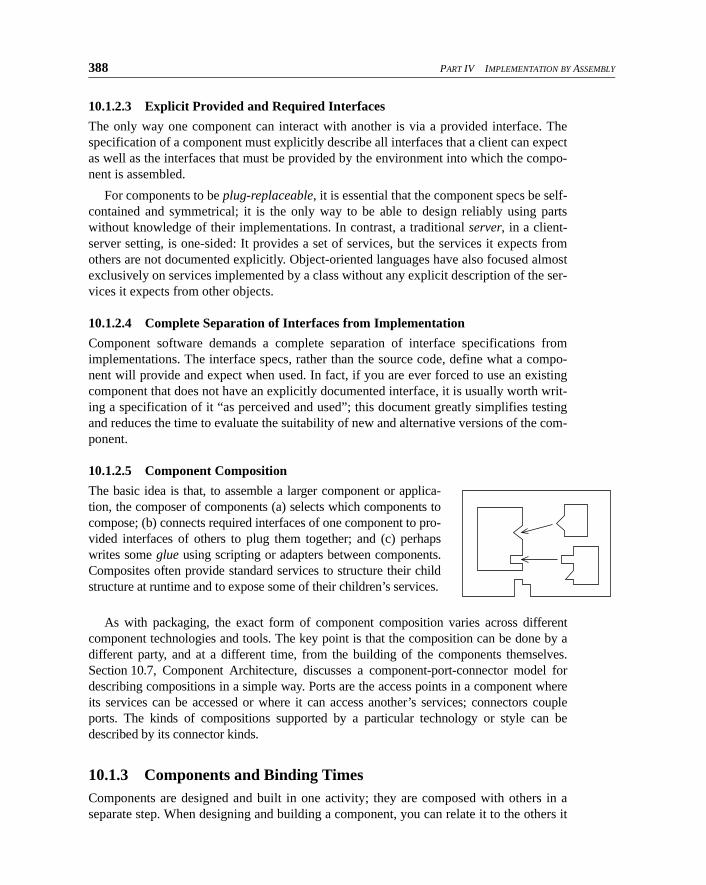
10.1.2.5 Component Composition
The basic idea is that, to assemble a larger component or applica-tion, the composer of components (a) selects which components tocompose; (b) connects required interfaces of one component to pro-vided interfaces of others to plug them together; and (c) perhapswrites some glue using scripting or adapters between components.Composites often provide standard services to structure their childstructure at runtime and to expose some of their children’s services.
As with packaging, the exact form of component composition varies across differentcomponent technologies and tools. The key point is that the composition can be done by adifferent party, and at a different time, from the building of the components themselves.Section 10.7, Component Architecture, discusses a component-port-connector model fordescribing compositions in a simple way. Ports are the access points in a component whereits services can be accessed or where it can access another’s services; connectors coupleports. The kinds of compositions supported by a particular technology or style can bedescribed by its connector kinds.
10.1.3 Components and Binding TimesComponents are designed and built in one activity; they are composed with others in aseparate step. When designing and building a component, you can relate it to the others it
Chapter 10 Components and Connectors 389
will (eventually) be composed with only by their contractual interfaces. Actual implemen-tations are selected at composition time or, sometimes, even at runtime. We usually wantto delay the bindings made when components are composed so that the composition canbe done as late as possible. One view of the range of binding times is shown in Table 10.1.
Exhibit 10.1 Binding Times for Composition
Binding Time How It Works
Coding time Straight-line code, without even procedural separation.
Compile time The standard separation of procedures; all calls are bound to an implementa-tion at compile time.
Link time Separate compilation units, with interfaces declared separately from their implementations; calls are compiled against interfaces and are bound when the compiled units are linked into an executable.
Dynamic linking Separate compilation units that do not need to be linked into a single execut-able up front; instead, a compiled unit (a DLL) can be dynamically linked into the running system. Calls are compiled against interfaces and are bound the first time the implementation is loaded.
Runtime Calls are compiled using a level of indirection; this indirection is used to dynamically bind a call against an interface to a specific implementation at runtime based on the “receiving” object; this can be combined with dynamic linking (Java) or static linking (C++).
Reflective Calls are not compiled against interfaces at compile time. Instead, the runt-ime keeps an explicit representation of interfaces offered; calls are issued dynamically against these at runtime based on “reflection” about the services and (of course) are resolved dynamically. Scripting services, in which com-ponents are coordinated by interpreted scripts, are best built on such a facil-ity.
10.1.4 Objects Versus ComponentsThere is confusion in popular writings about the similarity and differences between anobject and a component. Some of this confusion stems from the fact that component tech-nology is often best implemented using an object-oriented language; more fundamentally,it stems from loose usage of the terms object, class, and component.
10.1.4.1 Is an Object a Component?
Components are software artifacts and represent the work of software developers and theirtools; objects are identifiable instances created in running systems by executing code thatis a part of some component. So, in that strict sense, an object is not a component. It is thecomponent code that is reused—the calendar package, perhaps with some customizableproperties—rather than a specific calendar instance and its state.
That said, a running component is often manifested as a collection of objects and canbe usefully treated as though it were one large-grained object, based on our approach to
390 PART IV IMPLEMENTATION BY ASSEMBLY
refinement. So we sometimes use the term component a bit more loosely in this chapter torefer to the object or set of objects that manifest a particular usage of a component in anapplication.
© component instance The object, set of objects, or predetermined configuration for such a set of objects that is the runtime manifestation of a component when composed within a particu-lar application.
10.1.4.2 Is a Class a Component?
Only if packaged to include explicit descriptions of the interfaces that it implements andthe interfaces it expects from others. Consider the following Java class:
class C1
implements I1, I2 -- interfaces this class implements{
public T0 foo (T1 x);private T2 y;
}
The minimal component that could contain C1 would also have to include the specifi-cations of I1, I2, T0, T1, and T2. A package with a single class; the interfaces it imple-ments (perhaps those interface specs are imported from another package); and theinterfaces it requires of any other objects it deals with (input parameters, returned objects,factory objects it uses to instantiate other objects, and so on) would constitute a minimalOO component.
If class C1 inherited part of its implementation from another class, there would be adirect implementation dependency between the classes. Many people believe that imple-mentation inheritance, although often useful, should not cross component boundaries.When the boundary must be crossed, it may be better to adopt a composition or delegationstyle approach (see Section 11.5.3, Polymorphism and Forwarding).
In general, a component could implement its interfaces by directly exposing them toclients or by implementing classes that provided the interfaces; to use the interfacer, cli-ents would need to obtain a handle to an instance of such a class.
10.1.4.3 Component-Based Design versus OO Design
When you build a design from components, you don’t need to know how they are repre-sented as objects or as instances of a classes or know how the connectors between compo-nents work.2 In federated systems, just as in OO programs, each component is a collectionof software; it is chosen for the support it provides of the corresponding business functionand uses local data representations best suited to the software. Just as in OO programs,objects must access the information held by other objects, so in a component architecture,components intercommunicate through well-defined interfaces so as to preserve mutualencapsulation.
The smaller-grained components in Section 10.6.1 and Section 10.6.2 are also verysimilar to objects. In fact, they would be easiest to implement as objects in an object-ori-ented programming language. This shows that the differences between component-based
Chapter 10 Components and Connectors 391
design and object-oriented design are mainly of degree and scale and are not intrinsic toeither type of design.
• Components often use persistent storage; although objects in an OO programming lan-guage always have local state, they typically work only within main memory, and per-sistence is dealt with separately.
• Components have a richer range of intercommunication mechanisms, such as events
and workflows, rather than only the basic OO message. These mechanisms support eas-ier composition of the parts.
• Components are often larger-grained than traditional objects and can be implemented
as multiple objects of different classes. They often have complex actions at their inter-faces, rather than single messages.
• A component package, by definition, includes definitions of the interfaces it provides
as well as the interfaces it requires; a traditional single class definition focuses on the
operations provided and not on the operations required.
• Objects tend to be dynamic; the number of customers, products, and orders you have, and their interconnections, changes dynamically. In contrast, larger-grained compo-nents may be more static; there will probably always be only one payment control and
one finance component, and their configuration will be static.
Components, like objects, interact through polymorphic interfaces. All our modelingtechniques apply equally well in both cases, including the more general connectors forcomponents. Plus, we can usefully talk about a component instance, component type, andcomponent class.
10.1.5 Components and Persistence A component instance has state represented by its object(s) and is part of a larger compo-nent. Hence, its persistence needs to be in the context of its containing component. Javaand COM provide differing versions of such protocols.
In simple cases, persistence can be achieved by a protocol by which a componentinstance serializes itself into a stream that is managed by its container. For larger, server-side components, each component can manage its own persistent storage and transactions;effective composition now requires that the container be able to coordinate nested transac-tions that cross its subcomponent boundaries. Enterprise JavaBeans, CORBA, MicrosoftTransaction Server, and COM+ provide their own versions of this.
2. Components can also be built without explicitly using object-oriented design techniques at all; but OO makes it a lot easier. If you tried to build a component architecture without mentioning objects, much of the technology you’d use would amount to object orientation anyway. We’ve recently read a few reports proclaiming ”Objects have failed to deliver! Components are the answer!” The authors either have a poor understanding of how componentware is built, or, being journalists and paid pundits, they enjoy a disconcerting headline. The reality is that OOP, like struc-tured programming before it, has become part of the body of ideas that constitute good software engineering. Having learned how to do it, we can now move on to putting it to work.
392 PART IV IMPLEMENTATION BY ASSEMBLY
10.2 The Evolution of Components
We should not assume that objects are intrinsic to component-based development; in fact,one of the advantages of components is that they can encapsulate legacy systems regard-less of how the systems are implemented inside. The idea of components goes back almostas far as the idea of software, but a number of things have changed significantly over theyears.
• The granularity of the components and the corresponding unit of pluggability: from
monolithic systems, to client-server partitions, to the operating system and its services, to today’s object-based component approaches.
• The effort and ease of dynamically connecting components to compose larger systems, from writing screen-scrapers for host-based systems (discussed in a moment) to creat-ing complex applications by visually configuring and connecting server-side compo-nents to one another and to user interfaces.
• The overall effort and cost of creating applications: from monolithic custom-made sys-tems to gigantic “package” solutions3 to the assembly of smaller components built on
standard infrastructure and interfaces.
The earliest mainframe-based systems were written as monolithic applications manipu-lating data shared across all the application procedures. Internal procedures could rarely beconsidered encapsulated; they typically operated on shared data, making composition at thatlevel difficult and error-prone. The only visible interface was to an external dumb terminal,and the nature of the interface was primitive: paint to the terminal screen and read charactercommands from the keyboard.
Calling these host-based applications “components” is a stretch; composing them waspainful. Because the only interface offered to the outside was to a dumb terminal, the onlyway to connect two such ”components” was to write pieces of code called screen-scrapersand terminal emulators. These programs acted as dumb terminals to the host but inter-preted the screen painting commands and generated character commands. The granularityof components was very large, connections could not be established dynamically, and thetechnology for connecting parts was primitive.4
At the time, it was possible to deliver complete applications only in the form of an exe-cutable. Moreover, the executable had to be prebuilt in a static manner and could be replacedor upgraded only as a single unit. Software libraries contained source code, which you usedby including the text and compiling it with your own.
But software vendors aren’t keen on letting people see their source code; they’d rathergive you the executable and (if you insist) the spec. This meant providing ways in which
3. These are sometimes so inflexible that they either work wonderfully for your business or your business must adapt to fit what the package solution offers.
4. This is changing substantially, with mainframe applications reborn as server-side components using technologies such as Enterprise JavaBeans.
Chapter 10 Components and Connectors 393
applications could communicate. In the early days, this meant that they passed files to oneanother, a slow process that required that every output and input from a program be con-verted to the form of external records. It lent itself to pipeline processing rather than dialogbetween programs.
This led to the development of the application program interface—which could be seenas a way in which a program could pretend to be an application’s user using facilities stan-dardized at the level of the operating system—and dynamic linking, which enabled codeto be linked at runtime without further processing. Two distinct forms of large-grainedcomponents evolved from this.
The first form led to client-server-styled systems, with the client combining user-interface and application logic and communicating via SQL requests with a databaseserver that dealt with persistence, transactions, security, and so on. All communicationinvolved database processing requests in SQL, and clients did not communicate withone another (except indirectly through shared data on the server).
Finer-grained application components also started to interact, using operating systemsupport. In the world of Windows, generic applications were built with APIs that enabledthem to be interconnected and interact via the operating system, exchanging informationthrough standardized data representation schemes. Thus, a spreadsheet application couldcommunicate with a word processor and a stock feeder to produce a formatted financialreport. In UNIX, we saw the emergence of the elegant, but limited, pipe-and-filter archi-tecture.
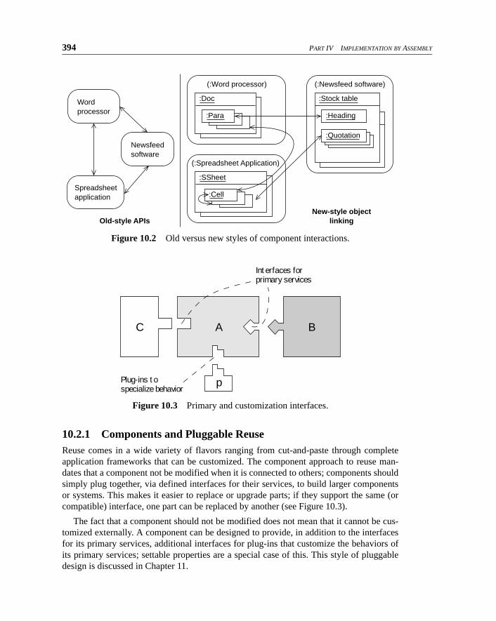
The first APIs were sets of functions that an external component could invoke. If therewas any notion of an object receiving the function calls, it was the entire running execut-able itself. But the most recent developments in this field have put the executable programinto the background (see Figure 10.2). The objects are the spreadsheet cells, the para-graphs in the document, the points on the graph; the application software is only the con-text in which those objects execute. The component architecture determines what kinds ofobject interactions are allowed.
Clearly, the granularity of components became much finer with object technology. Nolonger was it only the spreadsheet interacting with the database; now it was the sheets andcells that were connected to the columns and rows in the database, generating paragraphsand tables in the word processor. These relatively dynamic objects connect to otherobjects, regardless of the applications within which they exist.
The virtual enterprise of the future is built with components and objects locating eachother, connecting, and interacting on a standardized infrastructure. This happens for com-ponents of all granularity, from large server applications to fine-grained objects, acrossboundaries of language, processor, and even enterprise, and with binding times from com-pletely static to highly dynamic.
394 PART IV IMPLEMENTATION BY ASSEMBLY
10.2.1 Components and Pluggable ReuseReuse comes in a wide variety of flavors ranging from cut-and-paste through completeapplication frameworks that can be customized. The component approach to reuse man-dates that a component not be modified when it is connected to others; components shouldsimply plug together, via defined interfaces for their services, to build larger componentsor systems. This makes it easier to replace or upgrade parts; if they support the same (orcompatible) interface, one part can be replaced by another (see Figure 10.3).
The fact that a component should not be modified does not mean that it cannot be cus-tomized externally. A component can be designed to provide, in addition to the interfacesfor its primary services, additional interfaces for plug-ins that customize the behaviors ofits primary services; settable properties are a special case of this. This style of pluggabledesign is discussed in Chapter 11.
Figure 10.2 Old versus new styles of component interactions.
Figure 10.3 Primary and customization interfaces.
Wordprocessor
Newsfeedsoftware
Spreadsheetapplication
(:Word processor)
:Doc
:Para
Old-style APIsNew-style object
linking
(:Newsfeed software)
:Stock table
:Heading
(:Spreadsheet Application)
:SSheet
:Cell
:Quotation
Interfaces for primary services
C A B
pPlug-ins to specialize behavior
Chapter 10 Components and Connectors 395
The precise meaning of a connection between components varies depending on theneeds of the application and the underlying component technology. It could range fromexplicit invocation of functions via the connection to higher-level modes such as transferof workflow objects, events being propagated implicitly, and so on. Section 10.7, Compo-nent Architecture, examines this in detail.
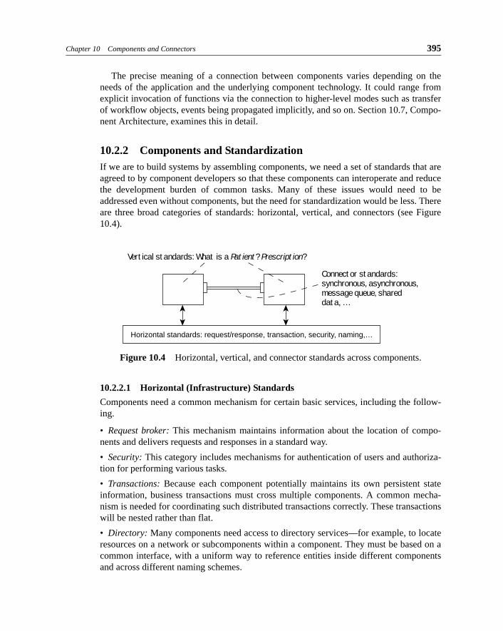
10.2.2 Components and StandardizationIf we are to build systems by assembling components, we need a set of standards that areagreed to by component developers so that these components can interoperate and reducethe development burden of common tasks. Many of these issues would need to beaddressed even without components, but the need for standardization would be less. Thereare three broad categories of standards: horizontal, vertical, and connectors (see Figure10.4).
10.2.2.1 Horizontal (Infrastructure) Standards
Components need a common mechanism for certain basic services, including the follow-ing.
• Request broker: This mechanism maintains information about the location of compo-nents and delivers requests and responses in a standard way.
• Security: This category includes mechanisms for authentication of users and authoriza-tion for performing various tasks.
• Transactions: Because each component potentially maintains its own persistent stateinformation, business transactions must cross multiple components. A common mecha-nism is needed for coordinating such distributed transactions correctly. These transactionswill be nested rather than flat.
• Directory: Many components need access to directory services—for example, to locateresources on a network or subcomponents within a component. They must be based on acommon interface, with a uniform way to reference entities inside different componentsand across different naming schemes.
Figure 10.4 Horizontal, vertical, and connector standards across components.
Vertical standards: What is a Patient? Prescription?
Horizontal standards: request/response, transaction, security, naming,…
Connector standards:synchronous, asynchronous,message queue, shared data, …
396 PART IV IMPLEMENTATION BY ASSEMBLY
• Interface repository: Component interfaces and their specifications must be defined in acommon way so that they can be understood both by people and by other components.
10.2.2.2 Vertical Standards
In addition to the underlying mechanisms being shared, components must agree on thedefinition of problem domain terms—usually manifested as problem domain objects—onwhich they will jointly operate. Components in a medical information system, for exam-ple, must share a common definition of what exactly a Patient is and what constitutes anOutpatient Treatment. They must share this definition at least in terms of the interfaces ofthose objects.
As of 1998, the OMG was actively working toward such vertical standards in domainsthat include telecommunications, insurance, finance, and medical care. Microsoft has aless coordinated effort under its DNA project. Every project must invariably also define itsown domain-specific standards.
10.2.2.3 Connector Standards
We must also use standard kinds of connectors between components, defining a variety ofinteraction mechanisms for various kinds of components and compositions. The basicobject-oriented message send is not the only, nor even the most suitable, way todescribe all interactions.
• Connectors that support explict call and return: The call could be synchronous or asyn-chronous. Asynchronous messages could be queued until processed, and return valuescould be treated as futures5 or callbacks.
• Connectors with impicit event propagation: Certain state changes in one component areimplicitly propagated to all components that registered an interest in that event.
• Connectors that directly support streams: Producers insert values or objects into thestream, where they remain until consumed by other components.
• Connectors that support workflow: Objects are transferred between one component andthe next, where this transfer is itself a significant event.
• Connectors that support mobile code: Rather than just receive and send data and refer-ences to objects, you can actually transmit an object, complete with the code that definesits behaviors.
10.2.3 Why the Move to Components?Components and component-based development are rapidly becoming buzzwords; likethose before them, they bring a mixture of hype and real technical promise. The mainadvantages of adopting a component-based approach to overall development are as fol-lows.
5. An encapsulation of a ”promise” of a value; it may block if the value is accessed before being available.

Chapter 10 Components and Connectors 397
• It permits reuse of implementation and related interfaces at medium granularity. A sin-gle domain object may not be a useful unit of reuse; a component—packaging together an implementation of services as it affects many domain objects—can be.
• Effective components also form the basic unit for maintenance and upgrading. There
should no longer be a need to upgrade entire “systems”; instead, components get replaced or added as needed.
• Component partitioning enables parallel development. Identifying medium-grained
chunks and focusing on early design of interfaces make it easier to develop and evolve
parts in parallel.
• Interface-centric design gives scalable and extensible architectures. By letting each
component have multiple interfaces, we reduce the dependency of any one component on irrelevant features of another component that it connects with. Also, adding new ser-vices incrementally can be accommodated more easily; you can introduce new compo-nents and add the relevant interfaces to existing ones. Scalability is somewhat more
easily addressed, because replication, faster hardware, and so on can be targeted at a
finer grain. Moreover, modern component technologies such as Enterprise JavaBeans
move many of the burdens of resource pooling and scaling away from the business
components to the containers within which they run.
• It lets you leverage standards. Because component technology implies a base set of standards for infrastructure services, a large application can leverage these standards
and save considerable effort as a result.
• It can support capabilities that are impractical for “small” objects, such as (1) language-independent access of interfaces—so that you can use components written in other lan-guages—and (2) transparent interaction between distributed components.
10.3 Building Components with Java
JavaBeans is the component technology for building components using Java. A JavaBeancan be a single Java class whose external interfaces are described using the following.
• Properties: Object attributes that can be read and written by access methods
• Methods: Services with specified effects that a client can invoke
• Events: State changes that an object will notify its environment about, with no expecta-tion of any resultant effect
Properties and methods represent services provided by the component. Events repre-sent notifications from the component. There is no explicit way to represent servicesrequired by the Bean.
JavaBeans was designed to distinguish properties, methods, and events without anychange to the basic Java language. It does this by using a facility called reflection.

398 PART IV IMPLEMENTATION BY ASSEMBLY
10.3.1 ReflectionJava retains an explicit runtime representation of class, interface, and method definitionsin its compiled class form; the reflection API is a facility for accessing this information.For every class that is loaded into a running system, Java instantiates a single instance ofthe predefined class Class. There is a static method for dynamically loading any classbased on its name and several methods for examining the structure of a class definition.
class Class {static Class forName(String); // load class by name, instantiate ClassClass getSuperclass(); // return the superclassClass[] getInterfaces(); // return list of interfaces implementedMethod[] getMethods(); // return list of methodsField[] getFields(); // return list of stored fieldsMethod[] getConstructors(); // return list of constructorsObject newInstance(); // create a new instance
}
There are several other related classes, of which the most interesting one is Method.
class Method {Class getDeclaringClass(); // return home classString getName(); // return method nameClass getReturnType(); // return typeClass[] getParameterTypes(); // list of parameter typesClass[] getExceptionTypes(); // list of exception typesvoid invoke(Object target); // (very late bound) method invocation
}
The following example illustrates a runtime use of these facilities:
// locate and load the class dynamicallyClass c = Class.forName (“UserDefinedClass”);
// instantiate the classObject o = c.newInstance ();
// get one of the methods on that classMethod m = c.getDeclaredMethod (“userMethod”, { } );
// invoke that method on the new instancem.invoke (o);
In addition to supporting the mechanisms needed by JavaBeans, as explained later, reflec-tion enables very late binding of calls by dynamically looking up interfaces and methodsand invoking them against objects of statically unknown types.
10.3.2 Basic JavaBeansThe simplest way to write a JavaBean is to program a single class, following certain nam-ing patterns for the methods on your class. Using the reflection API on an instantiated
Chapter 10 Components and Connectors 399
Bean (a process called introspection), a visual tool or other application can categorize themethods into properties, methods, and events.
• Property: Write a pair of methods named Y get<X>() and set<X>(Y) to define a prop-erty named X of type Y.
• Event: Write a pair of methods named add<X>Listener (XListener) and remove<X>Lis-tener (XListener) and add the event signature to the operations that the XListener inter-face must support; this defines a single event your bean can publish to registered
parties.
• Method: Write a method that follows neither a property nor an event pattern.
You can implement Beans without following the naming rules. You implement addi-tional methods on the bean that (indirectly) explicitly identify the methods correspondingto properties, events, and methods on that Bean. We omit the details here.
10.3.3 Improved Components with JavaBeansAttempting to program a Bean as a single class is not practical for nontrivial components;a component instance would typically consist of several connected objects of differentclasses, each implementing some of the external component interfaces. The more recentspecifications for JavaBeans make it simpler to build complex Beans from several classes.
• Do not use language primitive “casts” to access other interfaces of a component, because they would understand only language-level objects. Instead, there is a pre-scribed explicit query protocol for getting to other interfaces.
• Bean instances will be nested. The containing “context” may (1) provide standard con-tainment services and (2) interpose its own behavior before its parts execute their meth-ods. Standard interfaces are defined for this purpose.
10.3.4 PersistenceJava provides a light-weight serialization mechanism; the implementor need do no addi-tional work for objects to serialize and restore themselves correctly. The mechanism usesthe underlying reflection services to implement generic save and restore functionality onlyonce.
10.3.5 Packaging Using JAR FilesCompiled Java components are packaged into JAR files and include the class files thatimplement the component services, additional class files (if any) for explicitly definedproperties, methods, and events, and some additional information.
10.3.6 Enterprise JavaBeansServer components typically implement significant business functions and run on a server.In a multitier architecture, most business logic in an application runs on dedicated servers
400 PART IV IMPLEMENTATION BY ASSEMBLY
rather than on the client machine. In general, a multitier design increases the application’sscalability, performance, and reliability—because components can be replicated and dis-tributed across many machines—but at the cost of some “middleware” complexity. Java’sEnterprise JavaBeans (EJB) standard is a server component model that simplifies the pro-cess of moving business logic to the server by implementing a set of automatic services tomanage the component.
The Enterprise JavaBeans model lets you implement business functions as JavaBeansand then plug them in to a standard container that provides automatic management ofresources and contention from multiple threads, transaction programming based on two-phase commit across multiple independent components, and distributed programming. AnEJB component, packaged into a JAR file, has four main parts.
• Home interface: The client interface to a factory object that instantiates the main server Bean. A client locates this factory using a standard directory-based name lookup.
• Remote interface: The interface to the primary server Bean itself, providing the busi-ness operations to the client.
• EJB class: The class that implements the business operations.
• Deployment descriptor: A description of the preceding parts and additional attributes
such as transactional and security behaviors that can be decided at deployment time
rather than in the code for the main server component itself.
When the component, packed into its JAR file, is deployed, you must designate a
• Container: A component implemented by a middleware vendor; it acts as a container for your server component. It provides exposure of your services to clients (who actually do
not directly access your implementation), remote access, distributed transaction manage-ment, security (including authentication and authorization), resource pooling, concurrent service for multiple clients, clustering, and high availability. In short, a container gives you all the things that, if they were absent, would make implementing a multitier system
a nightmare.
Java presents a compelling technical base for component-based development, includ-ing enterprise-scale server components. Its main drawback is the single-language model,which is addressed by the integration of Java and CORBA.
Chapter 10 Components and Connectors 401
10.4 Components with COM+
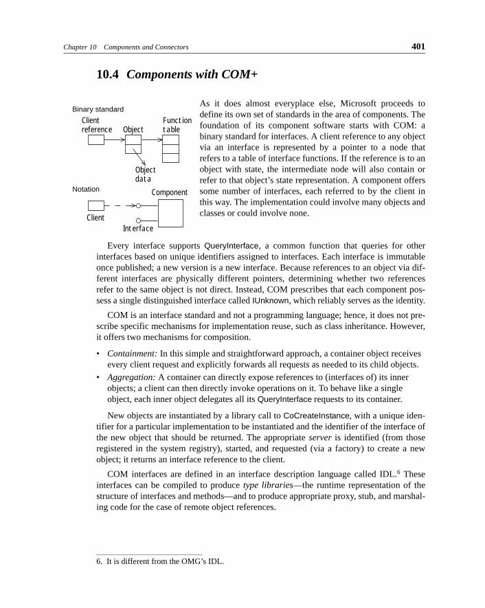
As it does almost everyplace else, Microsoft proceeds todefine its own set of standards in the area of components. Thefoundation of its component software starts with COM: abinary standard for interfaces. A client reference to any objectvia an interface is represented by a pointer to a node thatrefers to a table of interface functions. If the reference is to anobject with state, the intermediate node will also contain orrefer to that object’s state representation. A component offerssome number of interfaces, each referred to by the client inthis way. The implementation could involve many objects andclasses or could involve none.
Every interface supports QueryInterface, a common function that queries for otherinterfaces based on unique identifiers assigned to interfaces. Each interface is immutableonce published; a new version is a new interface. Because references to an object via dif-ferent interfaces are physically different pointers, determining whether two referencesrefer to the same object is not direct. Instead, COM prescribes that each component pos-sess a single distinguished interface called IUnknown, which reliably serves as the identity.
COM is an interface standard and not a programming language; hence, it does not pre-scribe specific mechanisms for implementation reuse, such as class inheritance. However,it offers two mechanisms for composition.
• Containment: In this simple and straightforward approach, a container object receives
every client request and explicitly forwards all requests as needed to its child objects.
• Aggregation: A container can directly expose references to (interfaces of) its inner objects; a client can then directly invoke operations on it. To behave like a single
object, each inner object delegates all its QueryInterface requests to its container.
New objects are instantiated by a library call to CoCreateInstance, with a unique iden-tifier for a particular implementation to be instantiated and the identifier of the interface ofthe new object that should be returned. The appropriate server is identified (from thoseregistered in the system registry), started, and requested (via a factory) to create a newobject; it returns an interface reference to the client.
COM interfaces are defined in an interface description language called IDL.6 Theseinterfaces can be compiled to produce type libraries—the runtime representation of thestructure of interfaces and methods—and to produce appropriate proxy, stub, and marshal-ing code for the case of remote object references.
Clientreference
FunctiontableObject
Objectdata
Binary standard
ClientInterface
ComponentNotation
6. It is different from the OMG’s IDL.
402 PART IV IMPLEMENTATION BY ASSEMBLY
COM does not have the equivalent of Java’s reflection, relying instead on the typelibrary. Consequently, scripting and other applications that require very late binding—inwhich even the method called is not compiled against an interface but is looked up at runt-ime—require explicit support in the component itself. Each component can support whatare called dispatch interfaces, in which a client requests an operation by a number; thecomponent resolves the mapping from numbers to methods to invoke. COM uses outgoinginterfaces to define events, just as JavaBeans uses its events.
COM includes a model for compound documents called OLE (a collection of standardCOM interfaces) and includes ActiveX controls, another set of COM interface standardsthat include outgoing interfaces to permit events to be signaled by a control to its con-tainer. ActiveX controls also have properties that are similar to JavaBeans properties.
COM+, a relatively recent entry in the furiously renamed space of Microsoft’s compo-nent technologies, has serious technology merit. It essentially defines a virtual machinemodel for components, similar in many respects to the Java virtual machine. COM+ pro-vides garbage collection (eliminating the pesky reference counting approach of COM),extensive metadata (permitting reflection and eliminating dispatch interfaces), and infra-structure services (security and transactions) for server-side components. One of its moreinteresting features is called interception: the ability for the virtual machine to interceptrequests sent to a component and interject special processing. This feature could be usedto provide late-bound cross-component services, much as Enterprise JavaBeans uses thecontainer as an intermediary to access component services.
10.5 Components with CORBA
CORBA (Common Object Request Broker Architecture) was designed by the Object Man-agement Group (OMG) to support open distributed communication between objects across awide variety of platforms and languages. Interestingly, despite the “Object” in its name,CORBA does not directly expose the notion of object identity; it could more properly beconsidered a distributed component framework.
To meet its goals of heterogenous computing, CORBA opted to become a source codestandard rather than a binary one. Component interfaces are defined within modules usingthe CORBA IDL; different programming languages have standardized bindings to theIDL. Programmers either (a) manually write IDL and then compile it into the source codeversions needed to write their implementations or (b) use a vendor’s programming lan-guage compiler that offers direct generation of IDL.
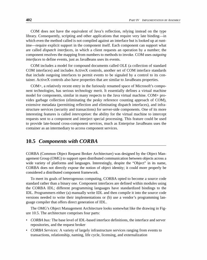
The OMG’s Object Management Architecture looks somewhat like the drawing in Fig-ure 10.5. The architecture comprises four parts:
• CORBA bus: The base level of IDL-based interface definitions, the interface and server repositories, and the request broker
• CORBA Services: A variety of largely infrastructure services ranging from events to
transactions, relationship, naming, life cycle, licensing, and externalization
Chapter 10 Components and Connectors 403
• CORBA Facilities (horizontal): Printing, e-mail, compound documents, structured
storage, workflow, and so on
• CORBA Facilities (vertical): Standards for business objects in “vertical” domains, including health care, telecomm, financials, and so on
CORBA recently defined mappings for the Java language and aligned closely with Jav-aBeans and Enterprise JavaBeans for its component model. In fact, the Java TransactionService is defined based on the CORBA model.
10.6 Component Kit: Pluggable Components Library
This section is about component kits: collections of components that are designed to workwith one another. The contents of a kit need not be completely fixed; you can add to it andhave various accessory kits and subkits of pieces that work particularly closely together. Buta kit has a unifying set of principles—the kit’s component architecture type—that makes iteasier to plug together the members of a kit successfully compared with components builtseparately or chosen from different kits. Plugging arbitrary components together usuallyrequires that you build some sort of glue. We deal with that in Section 10.11, HeterogenousComponents.
We’ll begin our discussion of component kits with an example to illustrate the basicprinciples and later show how they apply to larger-scale (and more business-oriented)components. These examples use various kinds of connectors between component instan-tiations, coupling service requirement points (ports) in one to service provision points(ports) in another. We use arrows and beads to represent connectors: .Section 10.8.2, Defining the Architecture Type, shows how varying kinds of connectorscan be defined.
10.6.1 Graphical User Interface Kit of ComponentsGUIs form the most widely used kits of components. Windows, scrollbars, buttons, textfields, and so on can be put together in many combinations and coupled to your database,
Figure 10.5 The CORBA architecture.
CORBA “bus”
CORBA Services
CORBAApplications
CORBAFacilities(vertical)
CORBAFacilities(horizontal)
404 PART IV IMPLEMENTATION BY ASSEMBLY
your Web server, or some other application. You rarely need to program the software thatsets up and builds the forms: Instead, you use a GUI wizard to design them directly.
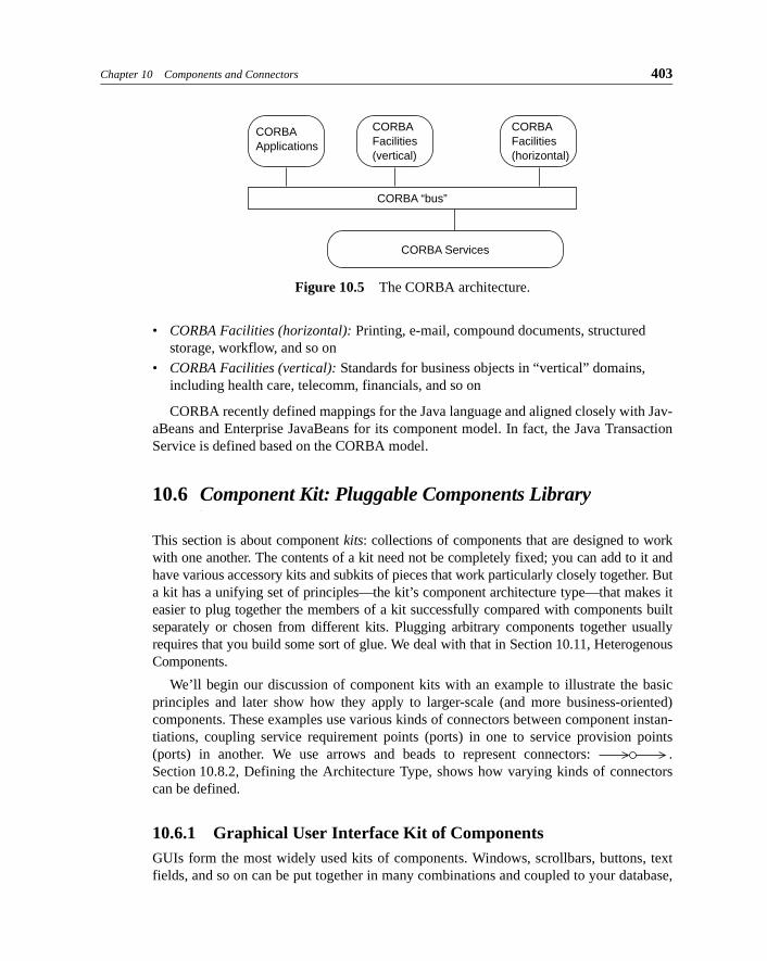
Using the connector notation discussed earlier, a typical design might look like the con-figuration of component instances shown in Figure 10.6. The connectors represent cou-plings between properties of two components ( ; a pair of values is kept continually insync) or events of two components ( ; a published occurrence from one componenttriggers a method of another component).
There is some need for adapters between, for example, the content of the Text Viewer andthe contact history of the Contact Record. The design calls for continuously updated proper-ties, such as the scrollbar’s connector to the Text Viewer, as well as events such as the But-ton’s hits. Some of the connectors are bidirectional: The checkbox both sets the priority andimmediately shows a change in the property.
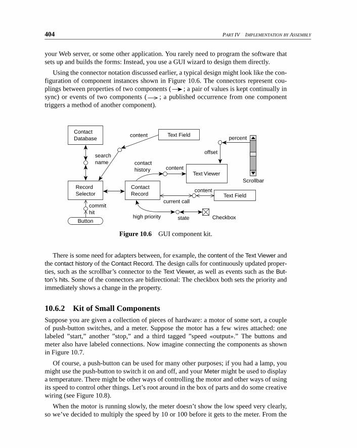
10.6.2 Kit of Small ComponentsSuppose you are given a collection of pieces of hardware: a motor of some sort, a coupleof push-button switches, and a meter. Suppose the motor has a few wires attached: onelabeled ”start,” another ”stop,” and a third tagged ”speed «output».” The buttons andmeter also have labeled connections. Now imagine connecting the components as shownin Figure 10.7.
Of course, a push-button can be used for many other purposes; if you had a lamp, youmight use the push-button to switch it on and off, and your Meter might be used to displaya temperature. There might be other ways of controlling the motor and other ways of usingits speed to control other things. Let’s root around in the box of parts and do some creativewiring (see Figure 10.8).
When the motor is running slowly, the meter doesn’t show the low speed very clearly,so we’ve decided to multiply the speed by 10 or 100 before it gets to the meter. From the
Figure 10.6 GUI component kit.
Contact Database
Contact Record
commithit
high priority state
current call
content
content
content
contacthistory
searchname
offset
Text Viewer
Text Field
Text Field
Record
Selector
Button
Scrollbar
Checkbox
percent

Chapter 10 Components and Connectors 405
box of components we’ve pulled a Multiplier and a Selector. A Selector is a user-interfacewidget that provides a fixed choice of values, which in this case we’ve set to the factorswe want to allow.
We’re also worried that the Motor might run too fast sometimes (perhaps if its load isremoved), so we’ve pulled out a Threshold.7 It converts a continuously varying value,such as the speed, into a Boolean off/on, switching on when its input rises above a certainlimit. Then we’ve connected it and the stop button (through an OR gate) to the Motor’sstop input. So the Motor will be stopped either by the button being pushed or the Motorrunning too fast.
Any model railroad enthusiast will recognize this as a neat kit of parts with which youcould build a lot of different projects—many more potential products than the number ofcomponents in the box. Note the ease of modifying the first version to realize the second.It’s not difficult to imagine such a kit in hardware nor to visualize it in software. The Motorcould be a software component controlling a hardware motor; the Buttons, Meter, andSelector could be user-interface widgets; and the other components could be objects notdirectly visible to the user.
Figure 10.7 Electronic hobbyist component kit.
Figure 10.8 Electronics kit: a nontrivial configuration.
7. Hardware people call it a Schmitt trigger.
Button
Button
Motor
startspeed value
stop
pressed
pressed
Meter
Button
Button
Threshold
OR
MotorSelector {1, 10, 100}
start
speed
in
ip1 ip2
value
selected
value
product
stop
pressed
overLimit
pressed
Meter
Multiplier
406 PART IV IMPLEMENTATION BY ASSEMBLY
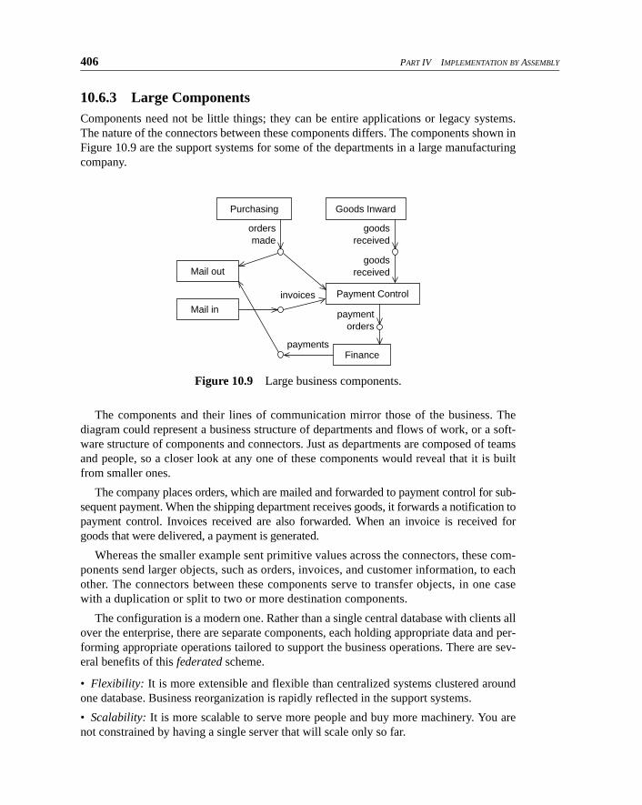
10.6.3 Large ComponentsComponents need not be little things; they can be entire applications or legacy systems.The nature of the connectors between these components differs. The components shown inFigure 10.9 are the support systems for some of the departments in a large manufacturingcompany.
The components and their lines of communication mirror those of the business. Thediagram could represent a business structure of departments and flows of work, or a soft-ware structure of components and connectors. Just as departments are composed of teamsand people, so a closer look at any one of these components would reveal that it is builtfrom smaller ones.
The company places orders, which are mailed and forwarded to payment control for sub-sequent payment. When the shipping department receives goods, it forwards a notification topayment control. Invoices received are also forwarded. When an invoice is received forgoods that were delivered, a payment is generated.
Whereas the smaller example sent primitive values across the connectors, these com-ponents send larger objects, such as orders, invoices, and customer information, to eachother. The connectors between these components serve to transfer objects, in one casewith a duplication or split to two or more destination components.
The configuration is a modern one. Rather than a single central database with clients allover the enterprise, there are separate components, each holding appropriate data and per-forming appropriate operations tailored to support the business operations. There are sev-eral benefits of this federated scheme.
• Flexibility: It is more extensible and flexible than centralized systems clustered aroundone database. Business reorganization is rapidly reflected in the support systems.
• Scalability: It is more scalable to serve more people and buy more machinery. You arenot constrained by having a single server that will scale only so far.
Figure 10.9 Large business components.
ordersmade
goodsreceived
goodsreceived
paymentorders
payments
invoices
Mail out
Purchasing Goods Inward
Payment Control
Finance
Mail in
Chapter 10 Components and Connectors 407
• Graceful degradation: Each business function is supported by its own machinery, soone malfunction doesn’t stop the whole enterprise.
• Upgradability: You do not have to set up and subsequently update the system as a singleentity. As the business grows and is reorganized, new software can be added. You can plugin commercial off-the-shelf components rather than build every enhancement into a singleprogram.
• Appropriateness: Because it requires less central control, it is less prone to local politi-cal and bureaucratic difficulties. There is no one authority that must agree to every changeor must be persuaded to address the evolving requirements of every department. Instead,the business users hold much more responsibility for providing support appropriate forthemselves.
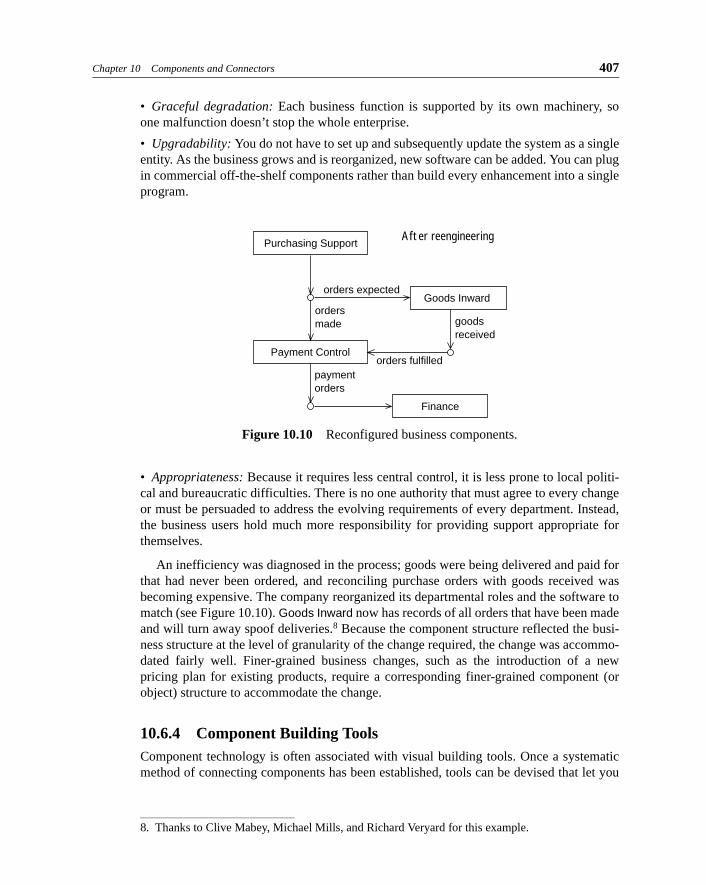
An inefficiency was diagnosed in the process; goods were being delivered and paid forthat had never been ordered, and reconciling purchase orders with goods received wasbecoming expensive. The company reorganized its departmental roles and the software tomatch (see Figure 10.10). Goods Inward now has records of all orders that have been madeand will turn away spoof deliveries.8 Because the component structure reflected the busi-ness structure at the level of granularity of the change required, the change was accommo-dated fairly well. Finer-grained business changes, such as the introduction of a newpricing plan for existing products, require a corresponding finer-grained component (orobject) structure to accommodate the change.
10.6.4 Component Building ToolsComponent technology is often associated with visual building tools. Once a systematicmethod of connecting components has been established, tools can be devised that let you
Figure 10.10 Reconfigured business components.
8. Thanks to Clive Mabey, Michael Mills, and Richard Veryard for this example.
After reengineering
orders
made
orders expected
orders fulfilled
goods
received
payment orders
Purchasing Support
Goods Inward
Payment Control
Finance
408 PART IV IMPLEMENTATION BY ASSEMBLY
to plug the components together graphically. Digitalk’s Parts and IBM’s Visual Age wereearly examples; Symantec’s Visual Café works in Java, as does Sun’s Java Workshop.Similar-sounding visual programming tools are restricted to building user interfaces ratherthan composing general components. There are tools (for example, Forté) that specializein distributed architectures, in which the components may be executing on differentmachines. Others are good at defining workflow systems in which components of onekind—work objects—are passed for multiple stages of processing between components ofanother kind, the work performers.
10.7 Component Architecture
An architecture is an abstraction of a system that describes the design structures and rela-tionships, governing rules, or principles that are (or could be) used across many designs.Here are examples:
“Four-tier with Web servelets.”
“We shall all write in Java.”
“Here’s how we make one property observe another.”
“Use these interfaces and protocols to implement a spell-checking feature.”
“Use Fred’s class whenever you want to wongle foobits.”
“Never use return codes to signal exceptions.”
The architecture is what lends the coherence and consistency to the design.
An architecture broadly comprises two parts (we defer a more detailed discussion toChapter 12, Architecture).
• The generic design elements or patterns that are used in the architecture, such as sub-ject-observer, Fred’s class, the event-property connectors, or the generic design for spell checking.
• The rules or guidelines that determine where and how these architectural elements are
applied, such as “For any composite user-interface panel that may be reused, make all internal events available via the composite.” In the extreme case, these rules can be for-malized to fully define a translation scheme.
Design is about relating several independent pieces together and claiming, “This particularway of combining these pieces will make something that does so-and-so.”
The pieces might be the result of applying architectural rules, or they might be asequence of statements making up a subroutine. They might be a group of linked objects,an assembly of hardware components, or large software subsystems that intercommuni-cate in some way. Or they might be a composition of several collaboration patterns onproblem domain objects. The essence of design is that the composition of various pieces,each one designed separately, somehow meets a requirement.
That said, we sometimes refer to a high-level partitioning structure as architecture,either technical architecture (having to do with underlying component technology, inde-
Chapter 10 Components and Connectors 409
pendent of business logic) or application architecture (having to do with partitioning ofapplication logic).
10.7.1 The Component-Port-Connector ModelThe rest of this chapter deals with how to model and specify components: executable unitsthat can be plugged together with different interaction schemes connecting them. Ourmodeling approach is based on the ideas put forth in three definitions.
© ports The exposed interfaces that define the plugs and sockets of the components; those
places at which the component offers access to its services and from which it accesses ser-vices of others. A plug can be coupled with any socket of a compatible type using a suitable
connector.
© connectors The connections between ports that build a collection of components into a soft-ware product (or larger component). A connector imposes role-specific constraints on the
ports that it connects and can be refined to particular interaction protocols that implement the
joint action.
To us, a component architecture defines the schemes of how components can beplugged together and interact. This definition may vary from one project or componentlibrary to another and includes schemes such as CORBA, DCOM, JavaBeans, databaseinterface protocols such as ODBC, and lower-level protocols such as TCP/IP as well assimpler sets of conventions and rules created for specific projects.
Component models are specifications of what a component does—based on a particularcomponent architecture, including the characteristics of its connectors—and descriptionsof connections between components to realize a larger design.
© component-based design The mind-set, science, and art of building with and for compo-nents and ensuring that the result of plugging components together has the expected effect.
It’s impossible to allow a designer to stick components together just any old way: Anoutput that yields a stream of invoice objects can’t be coupled to an input that acceptshotel reservation cancellation events. But we would like to be able, at least within one kitof components, to couple any input with any type-compatible output if their behaviors arecompatible. To be able to do this confidently across independently developed componentsmeans that certain things must be decided across the whole kit.
• Specification: What must you do to specify a particular component, with its input andoutput ports?
• Instantiation: What must you do to create an instance of a component and to couplecomponents together?
• Connectors: How do connectors (connections between components) work—as functioncalls, messages on wires, data shared between threads, or some other way? If there are dif-ferent kinds of connectors, what are they, and how do their implementations differ?
• Common model: What types are understood by all the components (only integers orCustomers too?)? How are objects represented as they are passed from one component toanother?
410 PART IV IMPLEMENTATION BY ASSEMBLY
• Common services: How does a component refer to an object stored within another?How are distributed transactions coordinated?
The answers to these questions are common across any set of components that canwork together (see Section 10.2.2, Components and Standardization). Together, they forma set of definitions and rules called a “component architecture.” Microsoft’s DCOM, theObject Management Group’s CORBA, and Sun’s JavaBeans are examples. Project teamsoften devise their own component architecture either independently or (more sensibly) asspecializations of these types. Highly generalized architectures cannot provide, for exam-ple, a common model of a Bank Customer, but this would be a sensible extension within abank.
In this chapter, we concern ourselves with architecture at the generic level of the kindsof ports and connectors supported, although, more broadly, an architecture definitioncould include much more.
10.7.1.1 Component Connector
We use arrows and beads to represent connectors, based on theUML notation for defining an interface and a dependency on it. However, ouruse of connectors between ports is more refined.
A type of connector is defined as a generic collaboration framework (see Chapter 9).The interactions between components can be complex, and part of the complexity comesfrom the techniques that permit them to be coupled in many configurations. The same pat-terns are repeated over and over—each time, for example, we want work to flow from onecomponent to another or we want a component to be kept up-to-date about the attributes ofanother.
Connectors hide complex collaborations. The stream of payment orders from PaymentControl probably requires a buffer along with a signaling mechanism to tell the receivingcomponent to pick up the orders. The stream of invoices from Purchasing follows thesame pattern. The continous update of the Meter’s value from the Motor’s speed requires achange-notification message; other values transmitted in that example need the same mes-sage.
Rather than describe these complex collaborations from scratch for each interface, weinvent a small catalog of connectors, which are patterns of collaboration that can beinvoked wherever components are to be plugged together. Then we can concentrate ononly the aspects that are specific for each connector, mainly the type of information trans-mitted.
A design described using connectors doesn’t depend on a particular way of implement-ing each category of connector. What’s important is that the designer know what each oneachieves. We can distinguish the component architecture model (which connectors can beused) from the component architecture implementation (how they work).
Chapter 10 Components and Connectors 411
10.7.1.2 Example Connectors
Each project or component library can define its own connectors to suit itself. In the Motorexample in Section 10.6.2, Kit of Small Components, we can identify two principal kindsof component connector:
• Events: Exchanges of information that happen when initiated by the sender to signal a
state change (shown with an open arrow: )
• Properties: Connectors in which an observer is continually updated about any change in a
named part of the state of the sender (shown with a solid arrow: )
The approach we discuss here also applies to other kinds of connectors such as the follow-ing:
• Workflow transfers: In which information moves away from a sender and into a
receiver
• Transactions: In which an object is read and translated into an editable or processable
form, is processed, and then updates the original
These are examples; you can define your own kinds of connectors to meet the needs ofyour enterprise. Being able to separately and explicitly define connector types lets us fur-ther decouple intercomponent dependencies from the component implementations andbetter abstract the structure of components when they are composed later.
10.7.2 Taxonomy of Component Architecture TypesThere can be many different implementations of a given architecture model, and the samearchitecture model can be applied to many different applications. A given componentarchitecture describes its type, or style, and its implementation.
© component architecture type, or style Which categories of connectors are permitted
between components, what each of them does, and the rules and constraints on their usage. Some (unary) connector types can even be used to define standard infrastructure services
that are always provided by the environment.
© architecture implementation(s) How each category of connector works internally, including
the protocol of interactions between ports.
Each component architecture does this, whether it uses widespread standards or isdefined by the architect of a particular project. Although the use of the big standards isimportant for intercoupling of large, widely marketed components, we believe that pur-pose-designed architectures will continue to be important within particular corporationsand projects and also within application areas (such as computer aided drafting, geograph-ical systems, and telecommunications) that have particular needs (such as image manipu-lation, timing, and so on). Therefore, it is necessary to understand what an architecturedefines, how to define your own architecture (see Section 10.8, Defining Cat One—AComponent Architecture), and how various architectures are related.
Like everything else, architectures have types (requirements specifications) and imple-mentations. A type defines what is expected of the implementation, and there may be
412 PART IV IMPLEMENTATION BY ASSEMBLY
many architecture implementations of a single architecture type. One architecture imple-mentation may be clever enough to implement more than one architecture type if they donot make conflicting demands. For example, most television broadcasts now carry bothpictures and pages of text, thereby accommodating separate architectural requirementswithin a single design of signal. Similarly, some architectural implementations allow twoarchitectures, such as CORBA and COM, to interoperate.
Like object types, architecture types can be extended: Extra requirements can be added(just as the transmission of color pictures was added to the original monochrome). A sim-ple version of the architecture discussed earlier defines event and property connectors; anextension might add transfers and transactions.
It’s important to remember that an architecture does not necessarily define any code.The type lays down rules for what the connectors achieve, and the architecture implemen-tation defines the collaborations to achieve that. The collaborations tell the designers ofthe components which messages they must send and in what sequence.
An architecture gives a component writer a set of ground rules and facilities. It does notnecessarily limit the kinds of interactions a component can have with another component;rather, it provides patterns for the most common kinds of interaction.
Suppose you are writing a component that accepts print jobs, queues them, and distrib-utes them among printers. An empty architecture is one in which nothing is predefined andevery component and interface must be defined from scratch. Without a laid-down archi-tecture, the documentation of your component must define
• Which operating system clients must use
• Which programming language (or set of calling conventions) must be used
• Which calls the client must make to inquire whether you can accept a job, to pass a job
to you, and confirm that you’ve received it
If you have a simple component architecture, it could minimally define operating sys-tem and language or clarify how to couple components working in different contexts. If itdefines no notion such as our transfer connector, you must define all the messages youexpect to send and receive.
But if it is a more sophisticated architecture that defines transfers, your job is muchsimpler: You only need to say exactly what type of object you’re transferring. The archi-tecture defines what “transfer”means and what messages achieve that effect; wherever youneed to, you simply use the transfer connector (as in using a framework application, dis-cussed in Chapter 15) and omit all the details.
So an architecture doesn’t limit the kinds of work that components can do together, butit makes it easier to document certain categories of interaction and thereby encourages theuse of components.
Chapter 10 Components and Connectors 413
10.8 Defining Cat One—A Component Architecture
There are an infinite number of interesting architectures, and the principles of component-based design we discuss apply regardless of specifics. Components can be connected in agreat variety of ways—using CORBA, COM, or even a daily manual FTP transfer—butall of them can be seen as examples of the basic notion of self-contained components cou-pled together using a set of connectors. The kinds of components and connectors and theway they are implemented vary from one architecture to another; for example, JavaBeans(see Section 10.3) offers a specific set.
In Catalysis, we view all component architectures as follows.
• Component: Any active element that performs a useful task we call a component. Com-ponents can be individual objects or large subsystems; they can even be the departments inan organization. In general, components differ from plain objects in being packaged morerobustly.
• Connector: Any means of communication between components we call a connector. Aconnector can be something as simple as a function call or a group of calls that provide fora collaboration, or it can be something more complex such as a dialog across an API. Or itmight be a message sent via CORBA or COM or a file transfer, a pipe, or even the deliv-ery of a deck of punched cards by courier. And of course, a GUI is a connector, just as auser is a component.
• Port: In general, each component has several identifiable means of being connected toothers. We call these ports; connectors connect ports together. Each port can be given aname (and, if there are a variable number of them, an index). For example, the operationson a plain object have their message names; the ports to an Internet host have numbers; thepins on a logic chip and the sockets on the back of your PC are tagged with specific func-tions; and many large systems have interfaces directed at different user roles.
Some architectures allow for restrictions on fan-out: the number of inputs supplied byeach output. In general, connections can be made and unmade dynamically, although thiscan be restricted in a particular architecture.
• Port category: In any architecture, there are different categories of ports characterizedby the style of information transfer: whether isolated events or streams of values, whetherbuffered, whether interactive, and so on. They are also differentiated by implementation:C++ function call, database transaction, FTP transfer, dictation over the phone, and so on.
• Component architecture: A component architecture is a choice of categories of connec-tors. They are specified first by what they achieve (signaling an event, updating values,transferring objects, and so on) and secondarily by how they are implemented (COM oper-ation, e-mail, carrier pigeon, and so on).
Most categories of port have a gender (such as «input» and «output») and a type ofvalue that is transmitted, from simple numbers to complex objects such as reservations orstock dealings. These elements also are defined by the specific component architecture,which also must define the rules whereby the ports can be connected (for example, aninput always to an output).
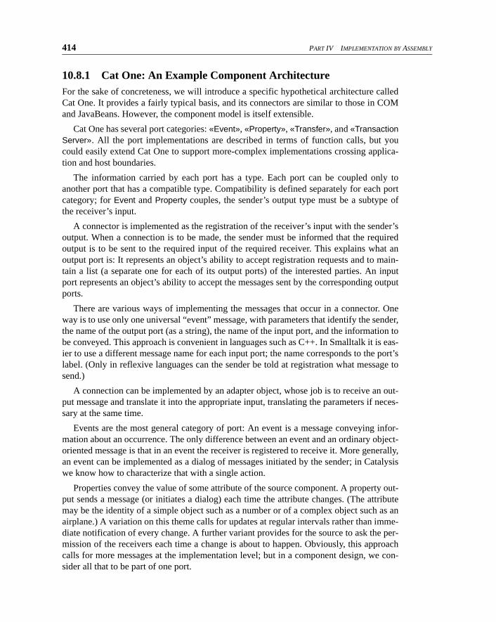
414 PART IV IMPLEMENTATION BY ASSEMBLY
10.8.1 Cat One: An Example Component ArchitectureFor the sake of concreteness, we will introduce a specific hypothetical architecture calledCat One. It provides a fairly typical basis, and its connectors are similar to those in COMand JavaBeans. However, the component model is itself extensible.
Cat One has several port categories: «Event», «Property», «Transfer», and «TransactionServer». All the port implementations are described in terms of function calls, but youcould easily extend Cat One to support more-complex implementations crossing applica-tion and host boundaries.
The information carried by each port has a type. Each port can be coupled only toanother port that has a compatible type. Compatibility is defined separately for each portcategory; for Event and Property couples, the sender’s output type must be a subtype ofthe receiver’s input.
A connector is implemented as the registration of the receiver’s input with the sender’soutput. When a connection is to be made, the sender must be informed that the requiredoutput is to be sent to the required input of the required receiver. This explains what anoutput port is: It represents an object’s ability to accept registration requests and to main-tain a list (a separate one for each of its output ports) of the interested parties. An inputport represents an object’s ability to accept the messages sent by the corresponding outputports.
There are various ways of implementing the messages that occur in a connector. Oneway is to use only one universal “event” message, with parameters that identify the sender,the name of the output port (as a string), the name of the input port, and the information tobe conveyed. This approach is convenient in languages such as C++. In Smalltalk it is eas-ier to use a different message name for each input port; the name corresponds to the port’slabel. (Only in reflexive languages can the sender be told at registration what message tosend.)
A connection can be implemented by an adapter object, whose job is to receive an out-put message and translate it into the appropriate input, translating the parameters if neces-sary at the same time.
Events are the most general category of port: An event is a message conveying infor-mation about an occurrence. The only difference between an event and an ordinary object-oriented message is that in an event the receiver is registered to receive it. More generally,an event can be implemented as a dialog of messages initiated by the sender; in Catalysiswe know how to characterize that with a single action.
Properties convey the value of some attribute of the source component. A property out-put sends a message (or initiates a dialog) each time the attribute changes. (The attributemay be the identity of a simple object such as a number or of a complex object such as anairplane.) A variation on this theme calls for updates at regular intervals rather than imme-diate notification of every change. A further variant provides for the source to ask the per-mission of the receivers each time a change is about to happen. Obviously, this approachcalls for more messages at the implementation level; but in a component design, we con-sider all that to be part of one port.
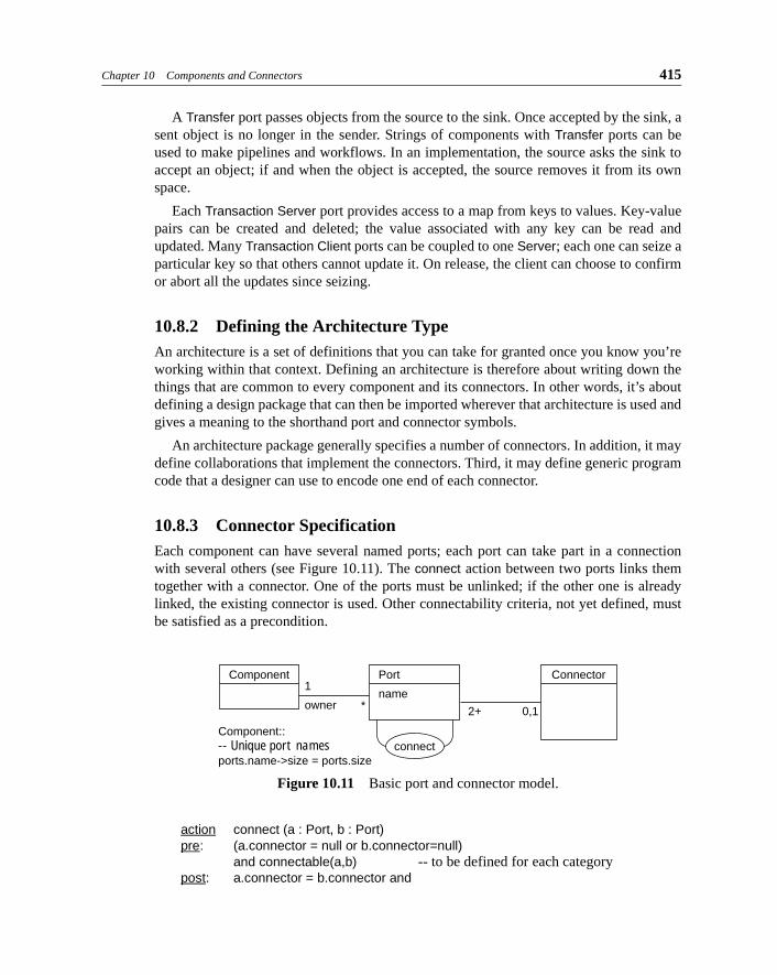
Chapter 10 Components and Connectors 415
A Transfer port passes objects from the source to the sink. Once accepted by the sink, asent object is no longer in the sender. Strings of components with Transfer ports can beused to make pipelines and workflows. In an implementation, the source asks the sink toaccept an object; if and when the object is accepted, the source removes it from its ownspace.
Each Transaction Server port provides access to a map from keys to values. Key-valuepairs can be created and deleted; the value associated with any key can be read andupdated. Many Transaction Client ports can be coupled to one Server; each one can seize aparticular key so that others cannot update it. On release, the client can choose to confirmor abort all the updates since seizing.
10.8.2 Defining the Architecture TypeAn architecture is a set of definitions that you can take for granted once you know you’reworking within that context. Defining an architecture is therefore about writing down thethings that are common to every component and its connectors. In other words, it’s aboutdefining a design package that can then be imported wherever that architecture is used andgives a meaning to the shorthand port and connector symbols.
An architecture package generally specifies a number of connectors. In addition, it maydefine collaborations that implement the connectors. Third, it may define generic programcode that a designer can use to encode one end of each connector.
10.8.3 Connector SpecificationEach component can have several named ports; each port can take part in a connectionwith several others (see Figure 10.11). The connect action between two ports links themtogether with a connector. One of the ports must be unlinked; if the other one is alreadylinked, the existing connector is used. Other connectability criteria, not yet defined, mustbe satisfied as a precondition.
action connect (a : Port, b : Port)pre: (a.connector = null or b.connector=null)
and connectable(a,b) -- to be defined for each categorypost: a.connector = b.connector and
Figure 10.11 Basic port and connector model.
1
owner
Component:: -- Unique port namesports.name->size = ports.size
Component Connector
connect
Port
name* 2+ 0,1
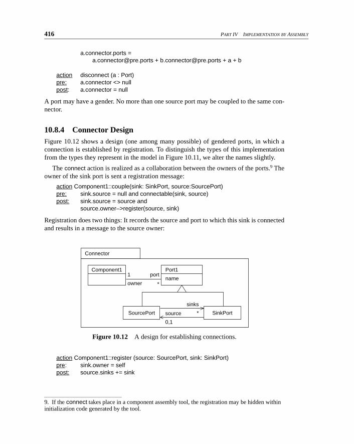
416 PART IV IMPLEMENTATION BY ASSEMBLY
a.connector.ports =
[email protected] + [email protected] + a + b
action disconnect (a : Port)pre: a.connector <> nullpost: a.connector = null
A port may have a gender. No more than one source port may be coupled to the same con-nector.
10.8.4 Connector DesignFigure 10.12 shows a design (one among many possible) of gendered ports, in which aconnection is established by registration. To distinguish the types of this implementationfrom the types they represent in the model in Figure 10.11, we alter the names slightly.
The connect action is realized as a collaboration between the owners of the ports.9 Theowner of the sink port is sent a registration message:
action Component1::couple(sink: SinkPort, source:SourcePort)pre: sink.source = null and connectable(sink, source)post: sink.source = source and
source.owner–>register(source, sink)
Registration does two things: It records the source and port to which this sink is connectedand results in a message to the source owner:
action Component1::register (source: SourcePort, sink: SinkPort)pre: sink.owner = selfpost: source.sinks += sink
9. If the connect takes place in a component assembly tool, the registration may be hidden within initialization code generated by the tool.
Figure 10.12 A design for establishing connections.
Component1
Connector
SourcePort
Port1
name1
owner
port
*
sinks
*source
0,1
SinkPort
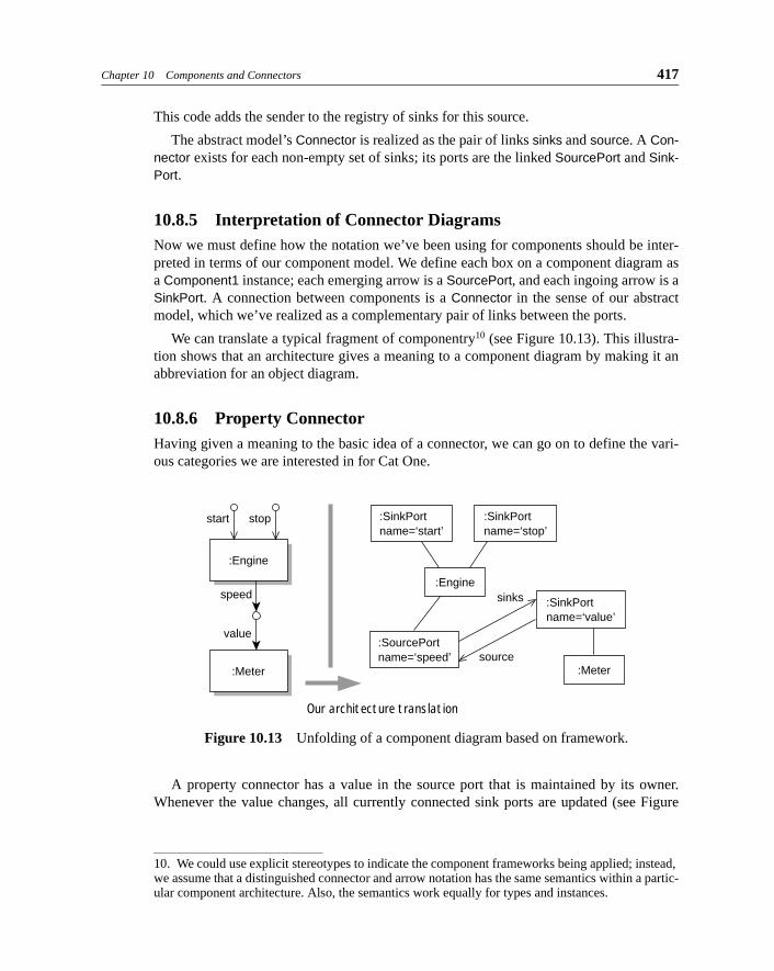
Chapter 10 Components and Connectors 417
This code adds the sender to the registry of sinks for this source.
The abstract model’s Connector is realized as the pair of links sinks and source. A Con-nector exists for each non-empty set of sinks; its ports are the linked SourcePort and Sink-Port.
10.8.5 Interpretation of Connector DiagramsNow we must define how the notation we’ve been using for components should be inter-preted in terms of our component model. We define each box on a component diagram asa Component1 instance; each emerging arrow is a SourcePort, and each ingoing arrow is aSinkPort. A connection between components is a Connector in the sense of our abstractmodel, which we’ve realized as a complementary pair of links between the ports.
We can translate a typical fragment of componentry10 (see Figure 10.13). This illustra-tion shows that an architecture gives a meaning to a component diagram by making it anabbreviation for an object diagram.
10.8.6 Property ConnectorHaving given a meaning to the basic idea of a connector, we can go on to define the vari-ous categories we are interested in for Cat One.
A property connector has a value in the source port that is maintained by its owner.Whenever the value changes, all currently connected sink ports are updated (see Figure
10. We could use explicit stereotypes to indicate the component frameworks being applied; instead, we assume that a distinguished connector and arrow notation has the same semantics within a partic-ular component architecture. Also, the semantics work equally for types and instances.
Figure 10.13 Unfolding of a component diagram based on framework.
Our architecture translation
:SinkPort name=‘start’
:Engine
start stop
speed
value
:Enginesinks
source:Meter:Meter
:SinkPort name=‘stop’
:SinkPort name=‘value’
:SourcePort name=‘speed’

418 PART IV IMPLEMENTATION BY ASSEMBLY
10.14). The PropertyConnector framework is applied for each connector marked «prop-erty» (for which an abbreviation is the filled arrow). The ports are labeled with the appro-priate substitutions for SourceType and SinkType; the type names should also be used togenerate separate types for the ports.
Suppose that we want to see how our architecture interprets the example shown in Fig-ure 10.15. The intent of this figure is that the aircraft shown in the aircraft display alwaystracks the current plane from the runway control; the ready status of the approach controltracks the clear status of the runway control.
We can translate first to a framework application: In the context of our composed compo-nent type, the framework relationships shown in Figure 10.16 on the next page hold between
the parts. The unfolded framework definitions are shown in Figure 10.17.
The complexity of this result is persuasive of the utility of the component notation. Thesame technique can be used to give meaning to any additional layer of notation and notonly to components. All this could be defined in a syntax section of the architecture pack-
Figure 10.14 Template for a property connector.
Figure 10.15 Component diagram to interpret.
PropertyConnector
PropertySourcePort :: -- Any value change must update all sinksinv effect value <> value@pre ==> sinks->forAll (sink | update(self, sink))
PropertySinkPort:: action update (source:Port, sink:Port) post: sink.value.equals(source.value)
PropertySourcePort
SourcePort SinkPort
value
SourceType
PropertySinkPort
SinkType
value
update
Connector
Runway Controlcurrent :Plane
show
:Aircraft
AirCraftDisplay
ApproachControlready : boolean
clear : boolean

Chapter 10 Components and Connectors 419
age itself along with a suitable mechanism for defining a visual grammar (see Chapter 9,Model Frameworks and Template Packages).
A straightforward generalization uses a recursive definition of port and connector,allowing us to make connections either at the level of individual events and properties orat higher-level bundles of them.
10.9 Specifying Cat One Components
When we specify a component, we take for granted the underlying architecture—mecha-nisms for registration to receive an output and the like—and focus on a higher-level speci-fication. Including outputs in a specification (marked «output property», «output event»,and so on or the equivalent solid arrow notation) implies that all this is assumed. A com-ponent specification takes the form of a single type description; but as always in Catalysis,it can be refined and implemented as a collection of objects.
Let’s now look at the main categories of ports in our Cat One architecture one by oneand see how to use specification techniques to define them.
Figure 10.16 Equivalent template applications.
Runway Control
PropertyConnector
PropertyConnector
PlaneSourcePort
Plane
SourceType
PropertySourcePort
BooleanSourcePort
boolean
PropertySourcePort
BooleanSinkPort
PropertySinkPort
SinkTypeSourceType
AirCraftSinkPort
PropertySinkPortComponent1
[port\current]
Component1
[port\clear]
Approach Control
Component1
[port\ready]
Aircraft
SinkType
AirCraftDisplay
Component1
[port\show]

420 PART IV IMPLEMENTATION BY ASSEMBLY
10.9.1 Specifying Input and Output EventsWe already know how to specify input events: this category corresponds to the actions oroperations that in previous chapters have been used to specify objects. The only differencecomes in the implementation and runtime effect. An object designed as a componentaccepts events according to the protocol defined in a chosen component architecture sothat it can be coupled to other components’ outputs, including any registration required forthose output events. Mechanics for mapping from the output event to the correspondinginput events—including string-based mapping, reflective techniques, or an adapterobject—are defined by the implementation of the architecture.
An output event occurs when a given change of state occurs.We can specify the change that stimulates the output, using the“old and new state” notation of postconditions within an effectinvariant (see Section 3.5.4, Effect Invariants). Notice the caretmark denoting that this message is scheduled to be sent. Here,we’ve declared the output event superfluously both in text andpictorially. («output event» pressed could have been omitted.)Output events can have arguments, which deliver information tothe receiving input events. The usual type matching rules apply.
Certain details of an output event are not specified in this style. For example, how soonafter a qualifying transition takes place must the output be made?11 Nor have we said who
Figure 10.17 Unfolded version of component diagram.
Plane
value value
show
ready
source
sinks
*
sinks
*
source
clear
Aircraft
AircraftDisplay
ApproachControl
BooleanSourcePort
value
boolean
value
boolean
BooleanSinkPort
current
PlaneSourcePort
Runway Control
AircraftSinkPort
Button
down : boolean
«output event» pressed
down and not down@pre
==> ^pressed
pressed
11. We can easily add performance specifications either informally or formally.

Chapter 10 Components and Connectors 421
will receive the output, because this will differ for each design in which the component isused; the architecture guarantees that all connected ports are notified.
Output events aren’t always coupled purely to a state change: an output may happenonly when the change is caused by a given input action. For example, our Button is agraphical user interface widget that responds to various mouse messages from the win-dowing system: let’s assume mouseUp, mouseDown, mouseEnter, and mouseLeave. Thelatter two happen if the user drags the mouse in or out of the Button’s screen area; the Upand Down messages are sent only when the mouse is within that area.
Let’s suppose that we want the operation stimulated by thebutton to take place when the user has pressed and releasedthe mouse. As the user presses, the Button changes color,and it changes back to normal as the release occurs. Butafter pressing, the user can make a last-moment decisionnot to do the action, signaling the change of mind by drag-ging the mouse away from the Button before releasing themouse key. In this case, the Button returns to the normalstate but does not send the output event.
The required behavior can be readily illustrated with astate chart. Alternatively, we can show the ^pressedrequirement as part of the postcondition of each actionthat causes it:
action mouseUppost: up and (down@pre ==> ^pressed)
Here are some useful abbreviations for events:
«input event» action (params) action(params)«output event» operation(params) ^ operation(params)
At a business level, a Warehouse component might publish an event outOf-Stock(Product) specified as
«output event» outOfStock (p: Product)inv effect p.stock@pre >= p.minumum & p.stock < minimum ==> ^outOfStock(p)
10.9.2 Specifying PropertiesInput and output properties provide a simple way to connect state variables across compo-nents.
Button
pressed
mouseUp
mouseDown
mouseEnter
mouseLeave
up
mouseLeave
mouseUp
^pressed
mouseDown
down
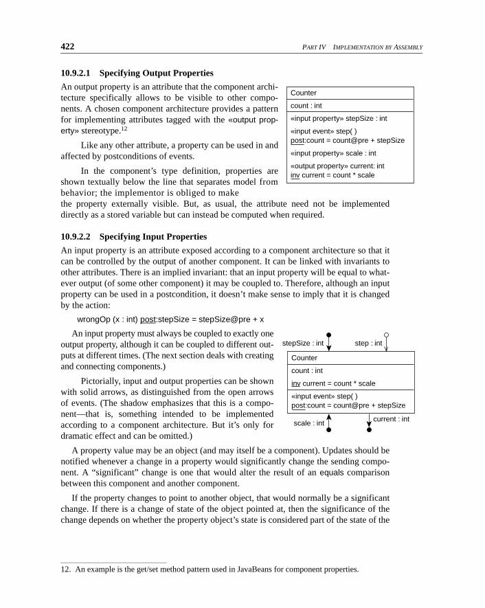
422 PART IV IMPLEMENTATION BY ASSEMBLY
10.9.2.1 Specifying Output Properties
An output property is an attribute that the component archi-tecture specifically allows to be visible to other compo-nents. A chosen component architecture provides a patternfor implementing attributes tagged with the «output prop-erty» stereotype.12
Like any other attribute, a property can be used in andaffected by postconditions of events.
In the component’s type definition, properties areshown textually below the line that separates model frombehavior; the implementor is obliged to make
the property externally visible. But, as usual, the attribute need not be implementeddirectly as a stored variable but can instead be computed when required.
10.9.2.2 Specifying Input Properties
An input property is an attribute exposed according to a component architecture so that itcan be controlled by the output of another component. It can be linked with invariants toother attributes. There is an implied invariant: that an input property will be equal to what-ever output (of some other component) it may be coupled to. Therefore, although an inputproperty can be used in a postcondition, it doesn’t make sense to imply that it is changedby the action:
wrongOp (x : int) post:stepSize = stepSize@pre + x
An input property must always be coupled to exactly oneoutput property, although it can be coupled to different out-puts at different times. (The next section deals with creatingand connecting components.)
Pictorially, input and output properties can be shownwith solid arrows, as distinguished from the open arrowsof events. (The shadow emphasizes that this is a compo-nent—that is, something intended to be implementedaccording to a component architecture. But it’s only fordramatic effect and can be omitted.)
A property value may be an object (and may itself be a component). Updates should benotified whenever a change in a property would significantly change the sending compo-nent. A “significant” change is one that would alter the result of an equals comparisonbetween this component and another component.
If the property changes to point to another object, that would normally be a significantchange. If there is a change of state of the object pointed at, then the significance of thechange depends on whether the property object’s state is considered part of the state of the
12. An example is the get/set method pattern used in JavaBeans for component properties.
Counter
count : int
«input property» stepSize : int
«input event» step( ) post:count = count@pre + stepSize
«input property» scale : int
«output property» current: int inv current = count * scale
Counter
count : int
inv current = count * scale
«input event» step( ) post:count = count@pre + stepSize
stepSize : int
current : intscale : int
step : int
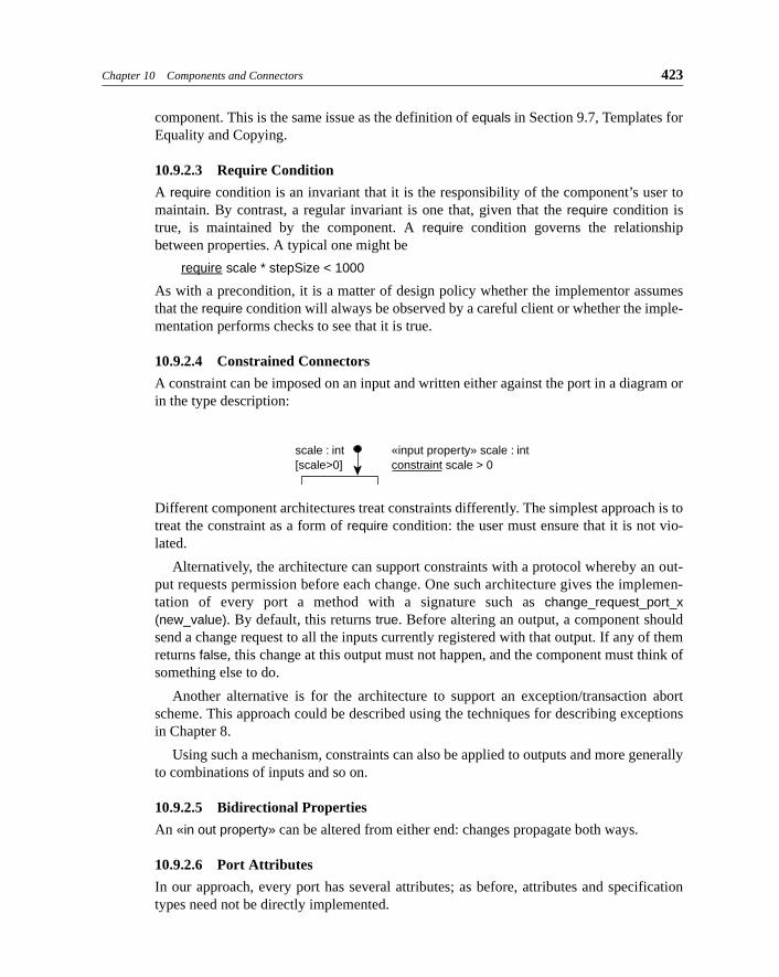
Chapter 10 Components and Connectors 423
component. This is the same issue as the definition of equals in Section 9.7, Templates forEquality and Copying.
10.9.2.3 Require Condition
A require condition is an invariant that it is the responsibility of the component’s user tomaintain. By contrast, a regular invariant is one that, given that the require condition istrue, is maintained by the component. A require condition governs the relationshipbetween properties. A typical one might be
require scale * stepSize < 1000
As with a precondition, it is a matter of design policy whether the implementor assumesthat the require condition will always be observed by a careful client or whether the imple-mentation performs checks to see that it is true.
10.9.2.4 Constrained Connectors
A constraint can be imposed on an input and written either against the port in a diagram orin the type description:
Different component architectures treat constraints differently. The simplest approach is totreat the constraint as a form of require condition: the user must ensure that it is not vio-lated.
Alternatively, the architecture can support constraints with a protocol whereby an out-put requests permission before each change. One such architecture gives the implemen-tation of every port a method with a signature such as change_request_port_x(new_value). By default, this returns true. Before altering an output, a component shouldsend a change request to all the inputs currently registered with that output. If any of themreturns false, this change at this output must not happen, and the component must think ofsomething else to do.
Another alternative is for the architecture to support an exception/transaction abortscheme. This approach could be described using the techniques for describing exceptionsin Chapter 8.
Using such a mechanism, constraints can also be applied to outputs and more generallyto combinations of inputs and so on.
10.9.2.5 Bidirectional Properties
An «in out property» can be altered from either end: changes propagate both ways.
10.9.2.6 Port Attributes
In our approach, every port has several attributes; as before, attributes and specificationtypes need not be directly implemented.
scale : int [scale>0]
«input property» scale : int constraint scale > 0

424 PART IV IMPLEMENTATION BY ASSEMBLY
• port.component: The component to which this port belongs.
• inputPort.source: The output port to which an input port is currently coupled.
• outputPort.sinks: The input ports to which an output port is currently coupled.
• propertyPort.value: The object or primitive that is output or input by this property port. Generally, when there’s no ambiguity it’s convenient to use the name of the property
port by itself, omitting the .value.
• propertyPort.constraint(value): A Boolean function returning, for an input property
port, whether the associated constraint is true for the given value—that is, whether it is
permissible to send this value to this port. For an output port, it is true if true for all the
currently coupled inputs.
Port attributes can be used in specifications. For example, suppose we want to insist thatthe Counter always be wired so that the component that sets its scale is the same one thatsets its stepSize:
requires
stepSize.source.component = scale.source.component
10.9.3 Specifying TransfersA transfer connector sends an object from the source component to the sink. In contrastwith events and properties, each «output transfer» port can be connected to only one «inputtransfer»; but the basic library of components includes a Duplicator component thataccepts one input and provides several outputs.
Like properties, transfers are characterized by the type of object transferred.
10.9.4 Specifying TransactionsA transaction connector provides for a property of the component to be locked againstalteration or reading by others; altered; and then either released in its new state or rolledback to its original state.
10.10 Connecting Cat One Components
Big components are made by connecting smaller ones. In this section we explain how theconnector types in our example architecture support composition.
10.10.1 Connector PropertiesAn input property can be driven by an output property, and each output can generally driveany number of inputs. A connection must match types: The output type must be the sameas, or a subtype of, the input type. The input and output can have different labels.
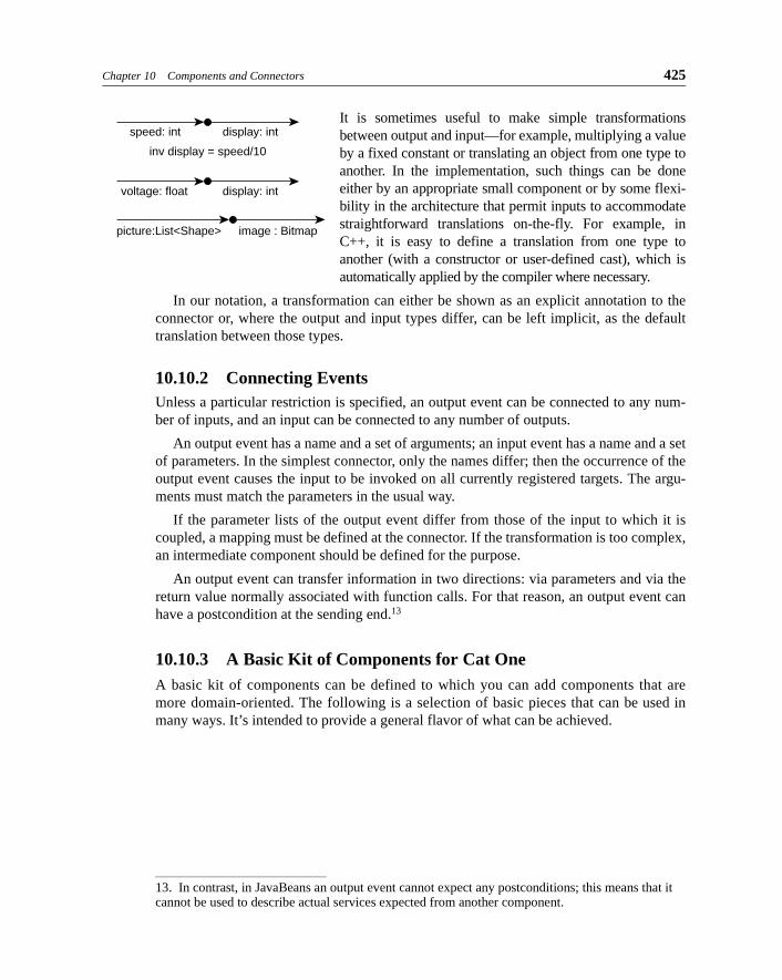
Chapter 10 Components and Connectors 425
It is sometimes useful to make simple transformationsbetween output and input—for example, multiplying a valueby a fixed constant or translating an object from one type toanother. In the implementation, such things can be doneeither by an appropriate small component or by some flexi-bility in the architecture that permit inputs to accommodatestraightforward translations on-the-fly. For example, inC++, it is easy to define a translation from one type toanother (with a constructor or user-defined cast), which isautomatically applied by the compiler where necessary.
In our notation, a transformation can either be shown as an explicit annotation to theconnector or, where the output and input types differ, can be left implicit, as the defaulttranslation between those types.
10.10.2 Connecting EventsUnless a particular restriction is specified, an output event can be connected to any num-ber of inputs, and an input can be connected to any number of outputs.
An output event has a name and a set of arguments; an input event has a name and a setof parameters. In the simplest connector, only the names differ; then the occurrence of theoutput event causes the input to be invoked on all currently registered targets. The argu-ments must match the parameters in the usual way.
If the parameter lists of the output event differ from those of the input to which it iscoupled, a mapping must be defined at the connector. If the transformation is too complex,an intermediate component should be defined for the purpose.
An output event can transfer information in two directions: via parameters and via thereturn value normally associated with function calls. For that reason, an output event canhave a postcondition at the sending end.13
10.10.3 A Basic Kit of Components for Cat OneA basic kit of components can be defined to which you can add components that aremore domain-oriented. The following is a selection of basic pieces that can be used inmany ways. It’s intended to provide a general flavor of what can be achieved.
speed: int
inv display = speed/10
display: int
voltage: float display: int
picture:List<Shape> image : Bitmap
13. In contrast, in JavaBeans an output event cannot expect any postconditions; this means that it cannot be used to describe actual services expected from another component.

426 PART IV IMPLEMENTATION BY ASSEMBLY
Standard Boolean processing of Booleanproperties: outputs are true when their inputshave the relationship marked. (The symbolscome from the tradition of electronic logic.)
In general, properties and events cannot becoupled. Change Detect generates events ontransition of a Boolean property.
The output of the S gate can be turned on,turned off, or inverted from its current value.
The Counter tracks inc and dec events.
The D gate freezes a copy of the variable inputat the moment the clock event occurs.
Transfer components:
• Buffer: a FIFO list; it accepts, or emits, any object (property) on request.
• Split: duplicates each input to all its outputs, where
each output meets the equal criteria on the input.
10.10.4 Dynamically Creating and Connecting ComponentsComponents can be instantiated and connected dynamically.
10.10.4.1 Connecting Components
The port attributes allow us to specify a connection in a postcondition, as in the followingexample:
Desk :: login(userName:String)post:directory.userWithName(userName).gui.source = self
and:boolean
:boolean
:boolean
:boolean
or:boolean:boolean
:booleannot:boolean
gone_truegone_falseChange Detect:boolean
:booleanS
on
flip
off
:intCounter
inc
zero
dec
frozenDvarying
clock
Bufferin
«transfer»
out
«transfer»
Split
out1
out2
out3
in
«transfer»
«transfer»
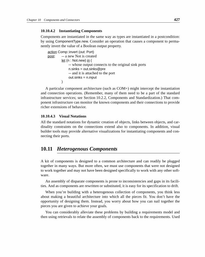
Chapter 10 Components and Connectors 427
10.10.4.2 Instantiating Components
Components are instantiated in the same way as types are instantiated in a postcondition:by using ComponentType.new. Consider an operation that causes a component to perma-nently invert the value of a Boolean output property.
action Comp::invert (out: Port)post: -- a new Not is created
let (n : Not.new) in (-- whose output connects to the original sink portsn.sinks = out.sinks@pre-- and it is attached to the portout.sinks = n.input
)
A particular component architecture (such as COM+) might intercept the instantiationand connection operations. (Remember, many of them need to be a part of the standardinfrastructure services; see Section 10.2.2, Components and Standardization.) That com-ponent infrastructure can monitor the known components and their connections to providericher extensions of behavior.
10.10.4.3 Visual Notations
All the standard notations for dynamic creation of objects, links between objects, and car-dinality constraints on the connections extend also to components. In addition, visualbuilder tools may provide alternative visualizations for instantiating components and con-necting their ports.
10.11 Heterogenous Components
A kit of components is designed to a common architecture and can readily be pluggedtogether in many ways. But more often, we must use components that were not designedto work together and may not have been designed specifically to work with any other soft-ware.
An assembly of disparate components is prone to inconsistencies and gaps in its facili-ties. And as components are rewritten or substituted, it is easy for its specification to drift.
When you’re building with a heterogenous collection of components, you think lessabout making a beautiful architecture into which all the pieces fit. You don’t have theopportunity of designing them. Instead, you worry about how you can nail together thepieces you are given to achieve your goals.
You can considerably alleviate these problems by building a requirements model andthen using retrievals to relate the assembly of components back to the requirements. Used
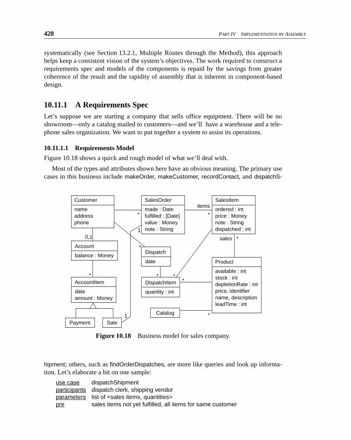
428 PART IV IMPLEMENTATION BY ASSEMBLY
systematically (see Section 13.2.1, Multiple Routes through the Method), this approachhelps keep a consistent vision of the system’s objectives. The work required to construct arequirements spec and models of the components is repaid by the savings from greatercoherence of the result and the rapidity of assembly that is inherent in component-baseddesign.
10.11.1 A Requirements SpecLet’s suppose we are starting a company that sells office equipment. There will be noshowroom—only a catalog mailed to customers—and we’ll have a warehouse and a tele-phone sales organization. We want to put together a system to assist its operations.
10.11.1.1 Requirements Model
Figure 10.18 shows a quick and rough model of what we’ll deal with.
Most of the types and attributes shown here have an obvious meaning. The primary usecases in this business include makeOrder, makeCustomer, recordContact, and dispatchS-
hipment; others, such as findOrderDispatches, are more like queries and look up informa-tion. Let’s elaborate a bit on one sample:
use case dispatchShipmentparticipants dispatch clerk, shipping vendorparameters list of <sales items, quantities>pre sales items not yet fulfilled, all items for same customer
Figure 10.18 Business model for sales company.
Customer
name
address
phone
AccountItem
date
amount : Money
SalesItem
ordered : int price : Money
note : String
dispatched : int
Product
available : int stock : int depletionRate : int price, identifier name, description
leadTime : int
Account
balance : MoneyDispatch
date
Catalog
Payment Sale
DispatchItem
quantity : int
SalesOrder
made : Date
fulfilled : [Date] value : Money
note : String
0,1
1
items
*
*
*
*
sales *
* *
*
*
1
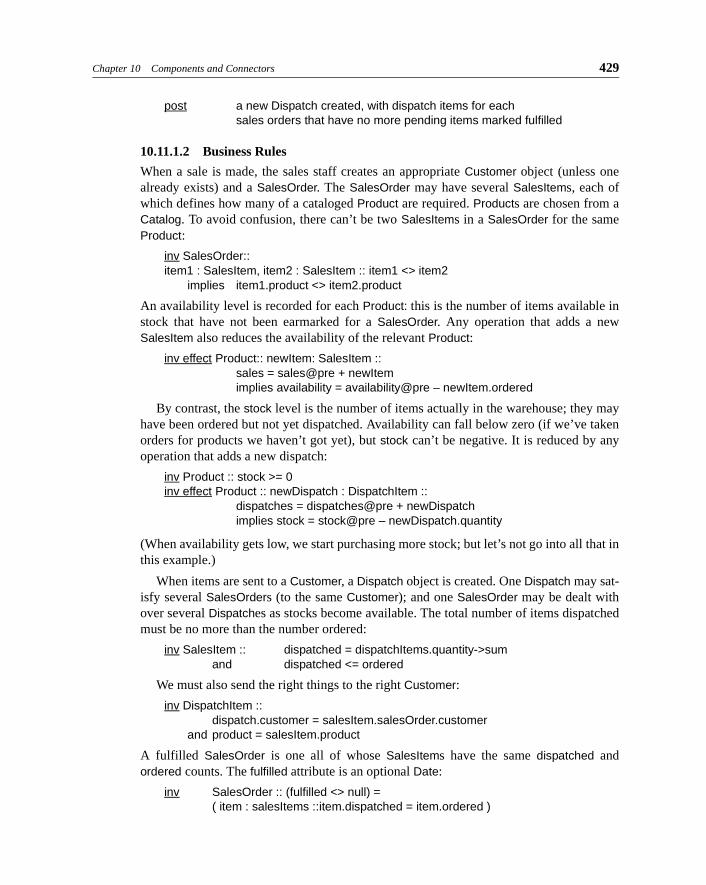
Chapter 10 Components and Connectors 429
post a new Dispatch created, with dispatch items for eachsales orders that have no more pending items marked fulfilled
10.11.1.2 Business Rules
When a sale is made, the sales staff creates an appropriate Customer object (unless onealready exists) and a SalesOrder. The SalesOrder may have several SalesItems, each ofwhich defines how many of a cataloged Product are required. Products are chosen from aCatalog. To avoid confusion, there can’t be two SalesItems in a SalesOrder for the sameProduct:
inv SalesOrder:: item1 : SalesItem, item2 : SalesItem :: item1 <> item2
implies item1.product <> item2.product
An availability level is recorded for each Product: this is the number of items available instock that have not been earmarked for a SalesOrder. Any operation that adds a newSalesItem also reduces the availability of the relevant Product:
inv effect Product:: newItem: SalesItem ::sales = sales@pre + newItemimplies availability = availability@pre – newItem.ordered
By contrast, the stock level is the number of items actually in the warehouse; they mayhave been ordered but not yet dispatched. Availability can fall below zero (if we’ve takenorders for products we haven’t got yet), but stock can’t be negative. It is reduced by anyoperation that adds a new dispatch:
inv Product :: stock >= 0inv effect Product :: newDispatch : DispatchItem ::
dispatches = dispatches@pre + newDispatchimplies stock = stock@pre – newDispatch.quantity
(When availability gets low, we start purchasing more stock; but let’s not go into all that inthis example.)
When items are sent to a Customer, a Dispatch object is created. One Dispatch may sat-isfy several SalesOrders (to the same Customer); and one SalesOrder may be dealt withover several Dispatches as stocks become available. The total number of items dispatchedmust be no more than the number ordered:
inv SalesItem :: dispatched = dispatchItems.quantity->sum
and dispatched <= ordered
We must also send the right things to the right Customer:
inv DispatchItem :: dispatch.customer = salesItem.salesOrder.customer
and product = salesItem.product
A fulfilled SalesOrder is one all of whose SalesItems have the same dispatched andordered counts. The fulfilled attribute is an optional Date:
inv SalesOrder :: (fulfilled <> null) =
( item : salesItems ::item.dispatched = item.ordered )
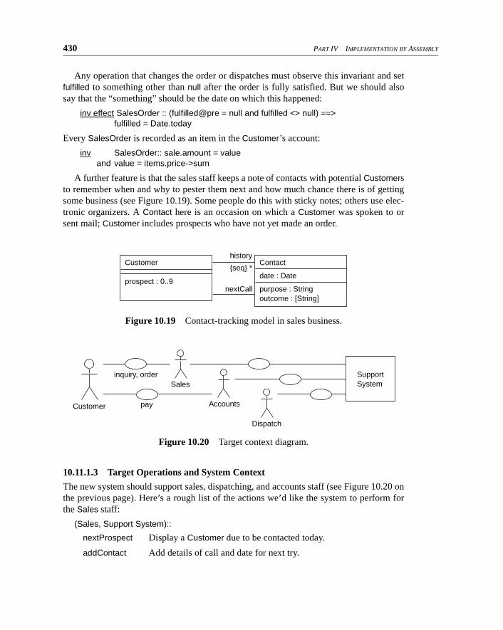
430 PART IV IMPLEMENTATION BY ASSEMBLY
Any operation that changes the order or dispatches must observe this invariant and setfulfilled to something other than null after the order is fully satisfied. But we should alsosay that the “something” should be the date on which this happened:
inv effect SalesOrder :: (fulfilled@pre = null and fulfilled <> null) ==>fulfilled = Date.today
Every SalesOrder is recorded as an item in the Customer’s account:
inv SalesOrder:: sale.amount = valueand value = items.price->sum
A further feature is that the sales staff keeps a note of contacts with potential Customersto remember when and why to pester them next and how much chance there is of gettingsome business (see Figure 10.19). Some people do this with sticky notes; others use elec-tronic organizers. A Contact here is an occasion on which a Customer was spoken to orsent mail; Customer includes prospects who have not yet made an order.
10.11.1.3 Target Operations and System Context
The new system should support sales, dispatching, and accounts staff (see Figure 10.20 onthe previous page). Here’s a rough list of the actions we’d like the system to perform forthe Sales staff:
(Sales, Support System)::
nextProspect Display a Customer due to be contacted today.
addContact Add details of call and date for next try.
Figure 10.19 Contact-tracking model in sales business.
Figure 10.20 Target context diagram.
Customer
prospect : 0..9
Contact
date : Date
purpose : String
outcome : [String]
history
{seq} *
nextCall
inquiry, order
pay
Sales
Customer Accounts
Dispatch
Support System
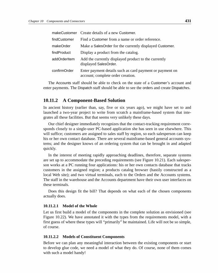
Chapter 10 Components and Connectors 431
makeCustomer Create details of a new Customer.
findCustomer Find a Customer from a name or order reference.
makeOrder Make a SalesOrder for the currently displayed Customer.
findProduct Display a product from the catalog.
addOrderItem Add the currently displayed product to the currently
displayed SalesOrder.
confirmOrder Enter payment details such as card payment or payment on
account; complete order creation.
The Accounts staff should be able to check on the state of a Customer’s account andenter payments. The Dispatch staff should be able to see the orders and create Dispatches.
10.11.2 A Component-Based SolutionIn ancient history (earlier than, say, five or six years ago), we might have set to andlaunched a two-year project to write from scratch a mainframe-based system that inte-grates all these facilities. But that seems very unlikely these days.
Our chief designer immediately recognizes that the contact-tracking requirement corre-sponds closely to a single-user PC-based application she has seen in use elsewhere. Thiswill suffice; customers are assigned to sales staff by region, so each salesperson can keephis or her own contact database. There are several mainframe-based general accounts sys-tems; and the designer knows of an ordering system that can be brought in and adaptedquickly.
In the interest of meeting rapidly approaching deadlines, therefore, separate systemsare set up to accommodate the preceding requirements (see Figure 10.21). Each salesper-son works at a PC running four applications: his or her own contacts database that trackscustomers in the assigned region; a products catalog browser (hastily constructed as alocal Web site); and two virtual terminals, each to the Orders and the Accounts systems.The staff in the warehouse and the Accounts department have their own user interfaces onthese terminals.
Does this design fit the bill? That depends on what each of the chosen componentsactually does.
10.11.2.1 Model of the Whole
Let us first build a model of the components in the complete solution as envisioned (seeFigure 10.22). We have annotated it with the types from the requirements model, with afirst guess of where these types will “primarily” be maintained. Life will not be so simple,of course.
10.11.2.2 Models of Constituent Components
Before we can plan any meaningful interaction between the existing components or startto develop glue code, we need a model of what they do. Of course, none of them comeswith such a model handy!
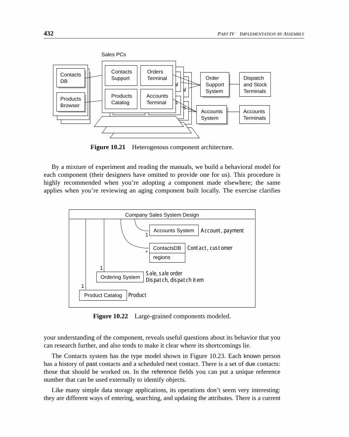
432 PART IV IMPLEMENTATION BY ASSEMBLY
By a mixture of experiment and reading the manuals, we build a behavioral model foreach component (their designers have omitted to provide one for us). This procedure ishighly recommended when you’re adopting a component made elsewhere; the sameapplies when you’re reviewing an aging component built locally. The exercise clarifies
your understanding of the component, reveals useful questions about its behavior that youcan research further, and also tends to make it clear where its shortcomings lie.
The Contacts system has the type model shown in Figure 10.23. Each known personhas a history of past contacts and a scheduled next contact. There is a set of due contacts:those that should be worked on. In the reference fields you can put a unique referencenumber that can be used externally to identify objects.
Like many simple data storage applications, its operations don’t seem very interesting:they are different ways of entering, searching, and updating the attributes. There is a current
Figure 10.21 Heterogenous component architecture.
Figure 10.22 Large-grained components modeled.
Orders
Terminal
Accounts
Terminal
Orders
Terminal
Accounts
Terminal
Order Support System
Accounts
System
Dispatch
and Stock
Terminals
Accounts
Terminals
Products
Browser
Contacts
DB
Contacts
Support
Products
Catalog
Orders
Terminal
Accounts
Terminal
Sales PCs
Product Catalog Product
Contact, customer
Account, payment
Sale, sale orderDispatch, dispatch item
1
1
1
*
Company Sales System Design
Ordering System
Accounts System
ContactsDB
regions
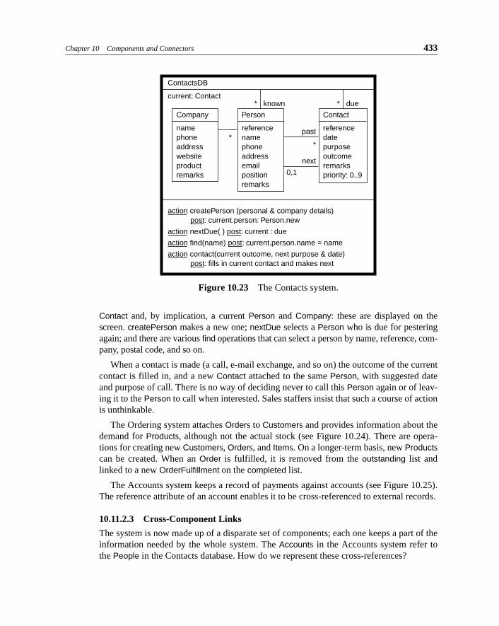
Chapter 10 Components and Connectors 433
Contact and, by implication, a current Person and Company: these are displayed on thescreen. createPerson makes a new one; nextDue selects a Person who is due for pesteringagain; and there are various find operations that can select a person by name, reference, com-pany, postal code, and so on.
When a contact is made (a call, e-mail exchange, and so on) the outcome of the currentcontact is filled in, and a new Contact attached to the same Person, with suggested dateand purpose of call. There is no way of deciding never to call this Person again or of leav-ing it to the Person to call when interested. Sales staffers insist that such a course of actionis unthinkable.
The Ordering system attaches Orders to Customers and provides information about thedemand for Products, although not the actual stock (see Figure 10.24). There are opera-tions for creating new Customers, Orders, and Items. On a longer-term basis, new Productscan be created. When an Order is fulfilled, it is removed from the outstanding list andlinked to a new OrderFulfillment on the completed list.
The Accounts system keeps a record of payments against accounts (see Figure 10.25).The reference attribute of an account enables it to be cross-referenced to external records.
10.11.2.3 Cross-Component Links
The system is now made up of a disparate set of components; each one keeps a part of theinformation needed by the whole system. The Accounts in the Accounts system refer tothe People in the Contacts database. How do we represent these cross-references?
Figure 10.23 The Contacts system.
* known
Company
name
phone
address
website
product remarks
ContactsDB
current: Contact
past
*
next
0,1
Person
reference
name
phone
address
email position
remarks
Contact
reference
date
purpose
outcome
remarks
priority: 0..9
* due
action createPerson (personal & company details) post: current.person: Person.new
action nextDue( ) post: current : due
action find(name) post: current.person.name = name
action contact(current outcome, next purpose & date) post: fills in current contact and makes next
*

434 PART IV IMPLEMENTATION BY ASSEMBLY
Links between types represent any association of the members of one type with themembers of the other type no matter how the association is implemented. Within a singlecomponent, associations typically may be implemented with memory address pointers;within a single database, associations may be implemented as pairs of keys in a table.Between components, an association represents a form of identification that each one rec-ognizes as referring to a single object within itself. For example, we could draw an associ-ation between Person (real ones) and the Personal_Records in a national Social Securitydatabase: the Social Security number identifies members of one type with those of theother.
Figure 10.26 Mapping component models and new business process to requirements.
In the company Sales system (see Figure 10.26), the link from Customer to Account isnot held in one component. The Accounts system doesn’t have a notion of Customer. Butwe can decide to use reference fields to cross-link them as foreign keys. Within each com-ponent, the CID (customer identifier) attributes uniquely identify one Person, Customer,and Account. The CID type itself is understood by all the components (and may be just a
Figure 10.24 The Ordering system.
Figure 10.25 The Accounts system.
* outstanding* completed
OrderFulfillment
date done
Ordering System
0,1
1..*
**
Customer
reference
name
address
phone
Order
id: Old
price
date made
Item
quantity
price
Product
catalog ref name
demand
* catalog
inv Product :: demand = items.quantity->sum
Account
reference
Accounts System
Item
amount reason: Old
date
*
*
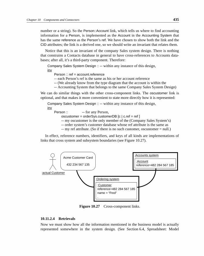
Chapter 10 Components and Connectors 435
number or a string). So the Person::Account link, which tells us where to find accountinginformation for a Person, is implemented as the Account in the Accounting System thathas the same reference as the Person’s ref. We have chosen to show both the link and theCID attributes; the link is a derived one, so we should write an invariant that relates them.
Notice that this is an invariant of the company Sales system design. There is nothingthat constrains a Contacts database in general to have cross-references to Accounts data-bases; after all, it’s a third-party component. Therefore:
Company Sales System Design :: -- within any instance of this design,inv
Person :: ref = account.reference-- each Person’s ref is the same as his or her account reference-- (We already know from the type diagram that the account is within the -- Accounting System that belongs to the same Company Sales System Design)
We can do similar things with the other cross-component links. The oscustomer link isoptional, and that makes it more convenient to state more directly how it is represented:
Company Sales System Design :: -- within any instance of this design,inv
Person :: -- for any Person, oscustomer = orderSys.customerDB [c | c.ref = ref ]-- my oscustomer is the only member of the (Company Sales System’s) -- order system’s customer database whose ref attribute is the same as-- my ref attribute. (So if there is no such customer, oscustomer = null.)
In effect, reference numbers, identifiers, and keys of all kinds are implementations oflinks that cross system and subsystem boundaries (see Figure 10.27).
10.11.2.4 Retrievals
Now we must show how all the information mentioned in the business model is actuallyrepresented somewhere in the system design. (See Section 6.4, Spreadsheet: Model
Figure 10.27 Cross-component links.
:Ordering system
:Customer reference=482 284 567 185
name = “Fred” .
:actual Customer
Acme Customer Card
432 234 567 135
:Accounts system
:Account reference=482 284 567 185
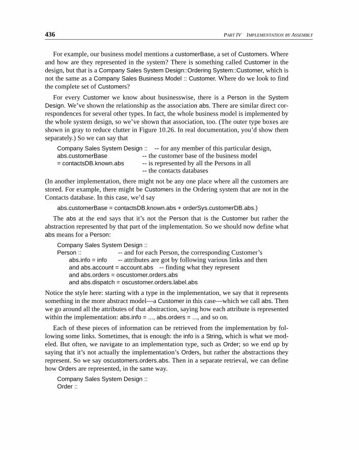
436 PART IV IMPLEMENTATION BY ASSEMBLY
For example, our business model mentions a customerBase, a set of Customers. Whereand how are they represented in the system? There is something called Customer in thedesign, but that is a Company Sales System Design::Ordering System::Customer, which isnot the same as a Company Sales Business Model :: Customer. Where do we look to findthe complete set of Customers?
For every Customer we know about businesswise, there is a Person in the SystemDesign. We’ve shown the relationship as the association abs. There are similar direct cor-respondences for several other types. In fact, the whole business model is implemented bythe whole system design, so we’ve shown that association, too. (The outer type boxes areshown in gray to reduce clutter in Figure 10.26. In real documentation, you’d show themseparately.) So we can say that
Company Sales System Design :: -- for any member of this particular design,abs.customerBase -- the customer base of the business model= contactsDB.known.abs -- is represented by all the Persons in all
-- the contacts databases
(In another implementation, there might not be any one place where all the customers arestored. For example, there might be Customers in the Ordering system that are not in theContacts database. In this case, we’d say
abs.customerBase = contactsDB.known.abs + orderSys.customerDB.abs.)
The abs at the end says that it’s not the Person that is the Customer but rather theabstraction represented by that part of the implementation. So we should now define whatabs means for a Person:
Company Sales System Design ::Person :: -- and for each Person, the corresponding Customer’s
abs.info = info -- attributes are got by following various links and thenand abs.account = account.abs -- finding what they representand abs.orders = oscustomer.orders.absand abs.dispatch = oscustomer.orders.label.abs
Notice the style here: starting with a type in the implementation, we say that it representssomething in the more abstract model—a Customer in this case—which we call abs. Thenwe go around all the attributes of that abstraction, saying how each attribute is representedwithin the implementation: abs.info = ..., abs.orders = ..., and so on.
Each of these pieces of information can be retrieved from the implementation by fol-lowing some links. Sometimes, that is enough: the info is a String, which is what we mod-eled. But often, we navigate to an implementation type, such as Order; so we end up bysaying that it’s not actually the implementation’s Orders, but rather the abstractions theyrepresent. So we say oscustomers.orders.abs. Then in a separate retrieval, we can definehow Orders are represented, in the same way.
Company Sales System Design ::Order ::
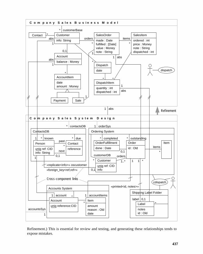
Refinement
Cross-component links
Customer
info: String
AccountItem
dateamount : Money
Person
uniq ref: CIDinfo: String
ContactsDB
Contact
reference
SalesItem
ordered : intprice : Moneynote : Stringdispatched : int
Account
balance : MoneyDispatch
date
Payment
Contact
C o m p a n y S a l e s B u s i n e s s M o d e l
Sale
DispatchItem
quantity : intdispatched : int
SalesOrder
made : Datefulfilled : [Date]value : Moneynote : String0,1
* customerBase
1
1
items
*
items
*
orders
*
*
*
*
*
*
1
abs
abs
1
abs
1
C o m p a n y S a l e s S y s t e m D e s i g n
* known
0,1
0,1
1
1
* due
* contactsDB 1 orderSys
1 abs
1 abs
past
*
next
* outstanding* completed
OrderFulfillment
done : Date
«replicate<info>» oscustomer
«foreign_key<ref,ref>»
«printed<id, notes>»
Ordering System
0,1
orderscustomerDB
1..* 1 1 ** Customer
uniq ref: CIDinfo
Label
notesid : Old
Order
id : Old
Item
Account
uniq reference:CID
Accounts SystemShipping Label Folder
cdispatch
Item
amountreason : Olddate
1 account 1 accountItems
accountsSys
1
*
* *label 0,1
dispatch
Refinement.) This is essential for review and testing, and generating these relationships tends toexpose mistakes.
437
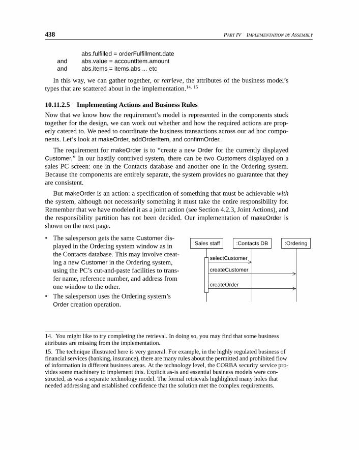
438 PART IV IMPLEMENTATION BY ASSEMBLY
abs.fulfilled = orderFulfillment.dateand abs.value = accountItem.amountand abs.items = items.abs ... etc
In this way, we can gather together, or retrieve, the attributes of the business model’stypes that are scattered about in the implementation.14, 15
10.11.2.5 Implementing Actions and Business Rules
Now that we know how the requirement’s model is represented in the components stucktogether for the design, we can work out whether and how the required actions are prop-erly catered to. We need to coordinate the business transactions across our ad hoc compo-nents. Let’s look at makeOrder, addOrderItem, and confirmOrder.
The requirement for makeOrder is to “create a new Order for the currently displayedCustomer.” In our hastily contrived system, there can be two Customers displayed on asales PC screen: one in the Contacts database and another one in the Ordering system.Because the components are entirely separate, the system provides no guarantee that theyare consistent.
But makeOrder is an action: a specification of something that must be achievable withthe system, although not necessarily something it must take the entire responsibility for.Remember that we have modeled it as a joint action (see Section 4.2.3, Joint Actions), andthe responsibility partition has not been decided. Our implementation of makeOrder isshown on the next page.
• The salesperson gets the same Customer dis-played in the Ordering system window as in
the Contacts database. This may involve creat-ing a new Customer in the Ordering system, using the PC’s cut-and-paste facilities to trans-fer name, reference number, and address from
one window to the other.
• The salesperson uses the Ordering system’s
Order creation operation.
14. You might like to try completing the retrieval. In doing so, you may find that some business attributes are missing from the implementation.
15. The technique illustrated here is very general. For example, in the highly regulated business of financial services (banking, insurance), there are many rules about the permitted and prohibited flow of information in different business areas. At the technology level, the CORBA security service pro-vides some machinery to implement this. Explicit as-is and essential business models were con-structed, as was a separate technology model. The formal retrievals highlighted many holes that needed addressing and established confidence that the solution met the complex requirements.
selectCustomer
createCustomer
createOrder
:Sales staff :Contacts DB :Ordering
Chapter 10 Components and Connectors 439
The Ordering system provides this action directly, although you must first look up theProduct in its list, which carries less information than the separate Web-browsable productcatalog.
The spec says, “Enters payment details, such as a credit card or payment on account.”According to one of the business rules (see Section 10.11.1.2), the order must be enteredas a sale in an Account associated with this Customer.
The Accounts system is entirely separate from the Ordering system, so it is up to thesales staff to copy the right numbers into the right accounts.
Again, we’re using the idea of action as specifying the outcome of a dialog betweenactors (people and components in this case). When people are involved, this generallymeans relying on them to do the right thing.
How would we describe the use case findOrderDispatches in our new business process?Let’s first look at the original requirements model; this use case is a query, and it is best tomake the specifications of queries trivial by adding convenience attributes to the model.So we add an attribute on SalesOrder:
SalesOrder::dispatches
-- it is all dispatches for any of my SalesItemsitems.dispatchItems.dispatch
action Agent::findOrderDispatches (order, out dispatches)post: result = order.dispatches
This requirements specification applies whether the underlying process is manual or auto-mated. The new version refines the required one:
action Agent::findOrderDispatcher (order#)-- the dispatches with labels whose orders include the target order#
post: result = shippingLabelFolder.labels[order.id->includes(order#)].dispatch
Similarly, the abstract dispatch use case is refined to cdispatch, which now involves theagent, the ordering system, and the shipping labels folder.
10.11.3 Glue ComponentsOnce the dust of setting up shop has settled a bit, we can make some improvements to thefirst support environment. We will move some work from the staff into the machine.
Sales staffers will now work through a Sales Client component (see Figure 10.28). Thisis an evolutionary change: the other components will stay exactly as they are. The SalesClient provides a single user interface to all the components used by the sales staff. Itimplements some of the cross-component business rules such as the Account-Order tie-up,eliminating that area of human error.
In this design, the Sales Client (which runs in each sales PC) integrates the third-partycomponents; but notice that they still do not talk directly to each other. Often, there is nofacility for this in older components. In a similar way, a Dispatch Client (used by the ware-
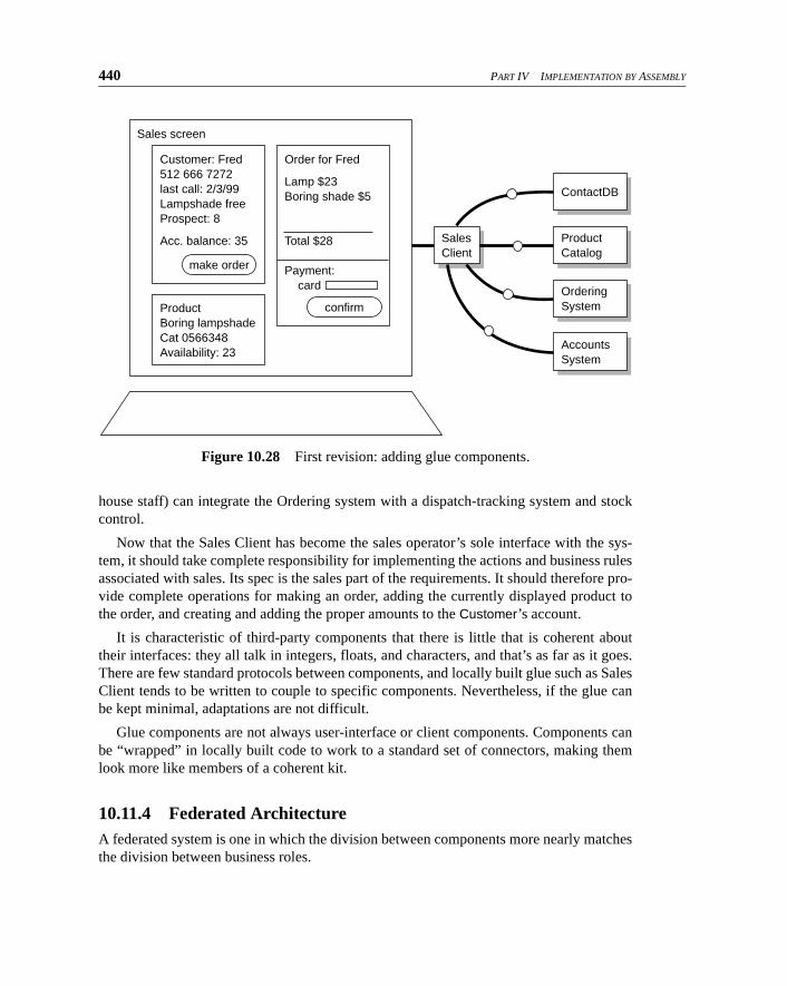
440 PART IV IMPLEMENTATION BY ASSEMBLY
house staff) can integrate the Ordering system with a dispatch-tracking system and stockcontrol.
Now that the Sales Client has become the sales operator’s sole interface with the sys-tem, it should take complete responsibility for implementing the actions and business rulesassociated with sales. Its spec is the sales part of the requirements. It should therefore pro-vide complete operations for making an order, adding the currently displayed product tothe order, and creating and adding the proper amounts to the Customer’s account.
It is characteristic of third-party components that there is little that is coherent abouttheir interfaces: they all talk in integers, floats, and characters, and that’s as far as it goes.There are few standard protocols between components, and locally built glue such as SalesClient tends to be written to couple to specific components. Nevertheless, if the glue canbe kept minimal, adaptations are not difficult.
Glue components are not always user-interface or client components. Components canbe “wrapped” in locally built code to work to a standard set of connectors, making themlook more like members of a coherent kit.
10.11.4 Federated ArchitectureA federated system is one in which the division between components more nearly matchesthe division between business roles.
Figure 10.28 First revision: adding glue components.
Sales screen
make order
Customer: Fred
512 666 7272
last call: 2/3/99
Lampshade free
Prospect: 8
Acc. balance: 35
confirm
Order for Fred
Lamp $23
Boring shade $5
Total $28
Payment: card
Product Boring lampshade
Cat 0566348
Availability: 23
ContactDB
Product Catalog
Ordering
System
Accounts
System
Sales
Client
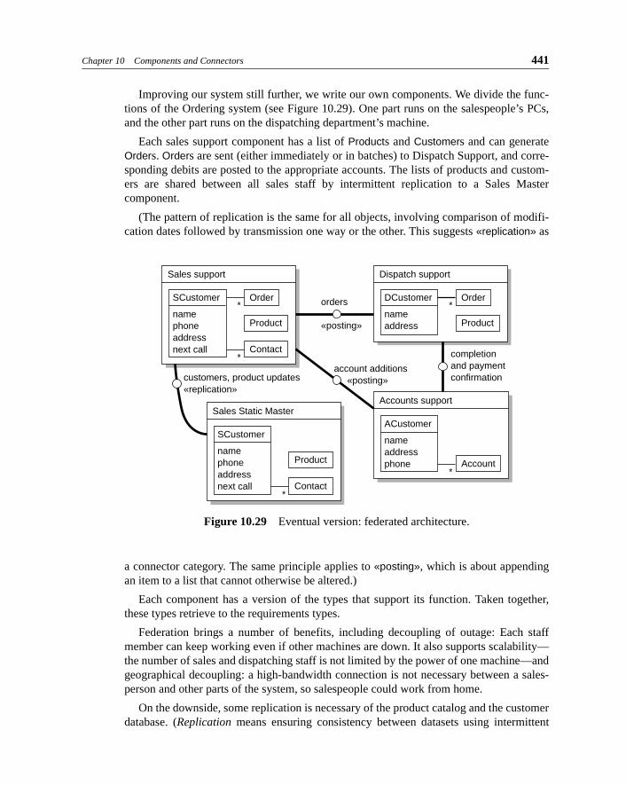
Chapter 10 Components and Connectors 441
Improving our system still further, we write our own components. We divide the func-tions of the Ordering system (see Figure 10.29). One part runs on the salespeople’s PCs,and the other part runs on the dispatching department’s machine.
Each sales support component has a list of Products and Customers and can generateOrders. Orders are sent (either immediately or in batches) to Dispatch Support, and corre-sponding debits are posted to the appropriate accounts. The lists of products and custom-ers are shared between all sales staff by intermittent replication to a Sales Mastercomponent.
(The pattern of replication is the same for all objects, involving comparison of modifi-cation dates followed by transmission one way or the other. This suggests «replication» as
a connector category. The same principle applies to «posting», which is about appendingan item to a list that cannot otherwise be altered.)
Each component has a version of the types that support its function. Taken together,these types retrieve to the requirements types.
Federation brings a number of benefits, including decoupling of outage: Each staffmember can keep working even if other machines are down. It also supports scalability—the number of sales and dispatching staff is not limited by the power of one machine—andgeographical decoupling: a high-bandwidth connection is not necessary between a sales-person and other parts of the system, so salespeople could work from home.
On the downside, some replication is necessary of the product catalog and the customerdatabase. (Replication means ensuring consistency between datasets using intermittent
Figure 10.29 Eventual version: federated architecture.
Sales support
SCustomer
name
phone
address
next call
Order
Product
Contact*
*
Dispatch support
DCustomer
name
address
Order
Product
*
Sales Static Master
customers, product updates
«replication»
account additions
«posting»
orders
«posting»
completion and payment confirmation
SCustomer
name
phone
address
next call
Product
Contact*
Accounts support
ACustomer
name
address
phone Account*

442 PART IV IMPLEMENTATION BY ASSEMBLY
updates, such as when a user logs in occasionally.) However, disk space isn’t very expen-sive, and the technology of replication has been much developed in recent years, particu-larly since its popularization by Lotus.
10.11.5 Summary: Heterogenous ComponentsA designer using a set of components that were not designed as a kit is faced with twoproblems:
• Matching their different and redundant views of similar concepts (such as Customer)
• Making their different connectors work together
Glue components can be built to translate the concepts and adapt the connectors; in thesimplest case, the users can perform those functions.
We have seen how a clear, high-level requirements specification, and the retrieval rela-tionship, helps clarify the relationship between the disparate designs of the components.We have also seen what needs to be done to unify them.
Chapter 10 Components and Connectors 443
Pattern 10.1 Extracting Generic Code Components
Reuse code by generalizing from existing work to make pluggable components.
IntentMake an existing component reusable in a broader context. Resources have been assignedfor work outside the immediate project need (see Pattern 10.2, Componentware Manage-ment).
ConsiderationsIt is often better to make a generic framework model, which requires less investment in theplug technology needed to make code components plug together. A framework model pro-vides only the specs for each class that fits into a framework and is typically specialized atdesign time. This arrangement is better for performance and requires less runtime plugga-bility.
It takes hard work to find the most useful generalization that fits many cases—and toget it right. This effort is worthwhile only for components that will be reused at least fouror five times; the investment doesn’t pay off for some time.
Strategy
Components Cross Projects. It is unusual for someone without much experience todesign a good generic component in advance; such components become apparent onlyafter you find yourself repeating similar design decisions. It is also not very helpful to findcomponents in isolation: They work best as part of a coherent kit. Within a small project,there is not much payoff in developing components: It’s easy to spend too much time hon-ing beautifully engineered components that aren’t used anywhere else. It’s therefore a far-sighted architectural job to decide which components are worth working on and integrat-ing into the local kit.
Identify Common Frameworks. Separate objects and collaborations that have commonfeatures into framework packages and reimport them to apply.
Don’t Overgeneralize. If you simply dream up generalizations, they will not work.
Identify Variable Functionality and Delegate to Separate Plug Objects. Any timeyou can encapsulate such variability into a separate object, do so.
Specify Plug Interfaces. Define what you need from anything that plugs into your com-ponent as well as what you provide to it. Provide the simplest model that makes sense.“Lower” interfaces generally need to know less than “upper” ones.

444 PART IV IMPLEMENTATION BY ASSEMBLY
Package Your Component. It should be delivered with the following.
• Its plug specifications.
• Its test harness for clients’ plugs—based on the plug spec. This takes one of two forms:
– A stand-alone harness that drives the plug-in and pronounces judgement
– A switchable monitor that checks pre- and postconditions during operation
• A selection of demo or default plug-ins.
The component may be part of a suite of components that can plug together in differentways.
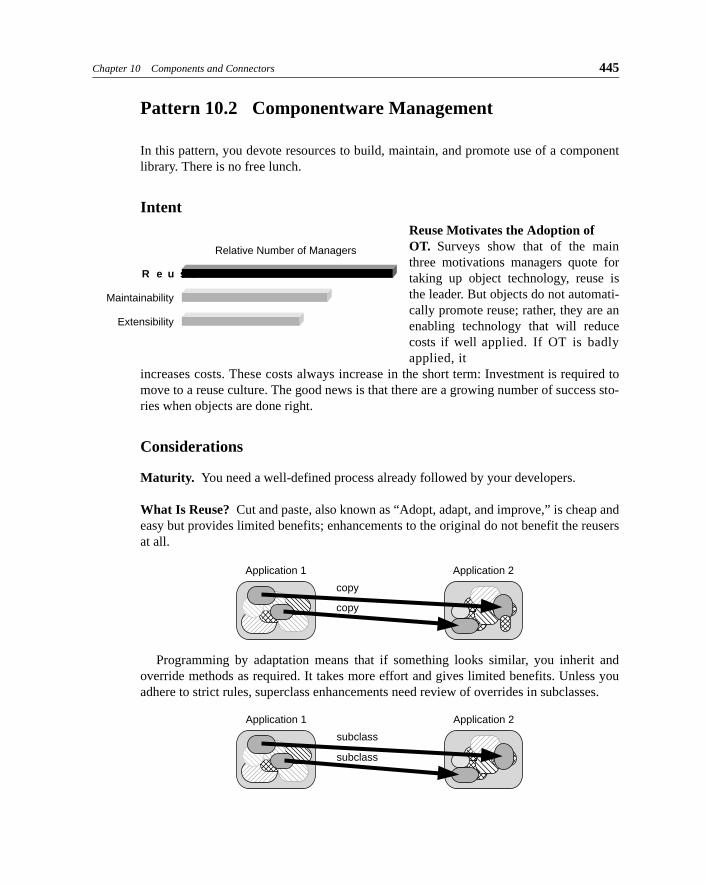
Chapter 10 Components and Connectors 445
Pattern 10.2 Componentware Management
In this pattern, you devote resources to build, maintain, and promote use of a componentlibrary. There is no free lunch.
IntentReuse Motivates the Adoption of OT. Surveys show that of the mainthree motivations managers quote fortaking up object technology, reuse isthe leader. But objects do not automati-cally promote reuse; rather, they are anenabling technology that will reducecosts if well applied. If OT is badlyapplied, it
increases costs. These costs always increase in the short term: Investment is required tomove to a reuse culture. The good news is that there are a growing number of success sto-ries when objects are done right.
Considerations
Maturity. You need a well-defined process already followed by your developers.
What Is Reuse? Cut and paste, also known as “Adopt, adapt, and improve,” is cheap andeasy but provides limited benefits; enhancements to the original do not benefit the reusersat all.
Programming by adaptation means that if something looks similar, you inherit andoverride methods as required. It takes more effort and gives limited benefits. Unless youadhere to strict rules, superclass enhancements need review of overrides in subclasses.
Relative Number of Managers
R e u s e
Maintainability
Extensibility
Application 1
copy
copy
Application 2
Application 1
subclass
subclass
Application 2
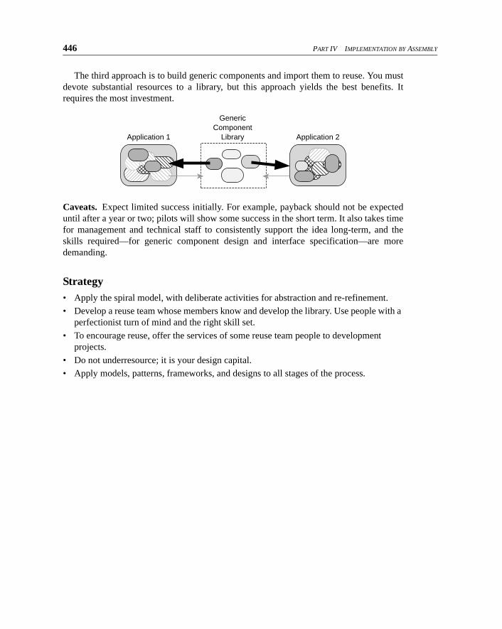
446 PART IV IMPLEMENTATION BY ASSEMBLY
The third approach is to build generic components and import them to reuse. You mustdevote substantial resources to a library, but this approach yields the best benefits. Itrequires the most investment.
Caveats. Expect limited success initially. For example, payback should not be expecteduntil after a year or two; pilots will show some success in the short term. It also takes timefor management and technical staff to consistently support the idea long-term, and theskills required—for generic component design and interface specification—are moredemanding.
Strategy• Apply the spiral model, with deliberate activities for abstraction and re-refinement.
• Develop a reuse team whose members know and develop the library. Use people with a
perfectionist turn of mind and the right skill set.
• To encourage reuse, offer the services of some reuse team people to development projects.
• Do not underresource; it is your design capital.
• Apply models, patterns, frameworks, and designs to all stages of the process.
Application 1 Application 2
GenericComponent
Library
Chapter 10 Components and Connectors 447
Pattern 10.3 Build Models from Frameworks
Do not build models from scratch but instead build them by composing frameworks.
IntentThe idea is to generalize modeling work so that you focus on reuse and componentware asearly as possible (see Pattern 10.2, Componentware Management).
ConsiderationsLarge models can be repetitive within similar business environments just as programdesigns are. And models also have variability that can be captured by different forms offactoring and parameterization.
A framework can be only a specification or can also include code implementation (seeChapter 11, Reuse and Pluggable Designs: Frameworks in Code). The latter requires moreinvestment in its design and may run slower. Pure specification frameworks help you builda spec, and then you must implement the result; it does not have the same runtime over-head of pluggability.
Strategy
Model-only Strategy. In this strategy, you build and use model frameworks.
• Look out for similar patterns within business models, type specifications, and high-level designs. Also, make frameworks for common design and analysis patterns.
• Extract common models and use placeholders, effects, invariant effects, and abstract actions to allow you to separate the parts of the models.
• Compose your framework with others. When one type has definitions from more than
one framework, use join composition (see Section 8.3.4, Joining Action Specifica-tions).
• Implement the composed framework. Each type in the composition will have a spec, which can be implemented as for the basic design.
• Use a tool that will help you compose model frameworks.
448 PART IV IMPLEMENTATION BY ASSEMBLY
Pattern 10.4 Plug Conformance
Two components fit together if their plug-points conform. Document them with refine-ments.
IntentEnsure that two components you’ve acquired (or built) will work with each other.
There are two specifications at a plug-point: the “services offered” advertisement ofone component and the “required” of the other. We must ensure that one matches the other.
How hard this is depends on whether the two components use similar terms. If one hap-pens to be designed specifically for the other, it’s easy. If that’s not the case but they arebased on the same business model, it’s not very difficult. If the models are entirely differ-ent, there’s more work to do (for example, see Section 10.11, Heterogenous Components).
Every model is based on imported others; with luck, components concerned with thesame business will import the same packages. Indeed, for this reason it is important tobase your specifications on imported models as much as possible.
StrategyDocument a refinement that shows how one component meets the other. See Chapter 6,Abstraction, Refinement, and Testing.
Chapter 10 Components and Connectors 449
Pattern 10.5 Using Legacy or Third-Party Components
Make a model of an existing component before using it. Create proxies to act as local rep-resentatives of the objects accessed through the component.
IntentThis pattern produces a uniform strategy across component boundaries, including legacycomponents.
Some of your software may be in the form of a third-party or legacy component. It maybe an infrastructure that you use to serve your middleware or may be part of the core of thesystem that implements part of the main business model.
For example, a library management system deals with loans, reservations, and stockcontrol. A third-party component is bought to deal with membership. This is a convention-ally written component (probably built atop a standard database) with an API that allowsmembers to be added, looked up, updated, and deleted.
Considerations
Model Translation. The component may (if you’re lucky!) come with a clearly definedmodel. If it doesn’t, it may be useful to build your own type model. The model will showthe component’s view of the information it deals with, together with the operations at theAPI. The model will not correspond precisely to your system model.
• It will not contain all the information. For example, the library manager knows each
member’s address, which books the member is currently holding, and what fines are
owed. Only part of this data will be stored in the membership manager.
• The component may be capable of storing other things we aren’t interested in for this
application, such as credit history.
• If the component’s model was written by someone else, its attributes and associations
may be radically different from those of your system model. For example, it may be
designed to associate “reference numbers” with several “short strings,” which you
intend to use for the member name and address.
Associations across Component Boundaries. Any kind of association crossing a compo-nent boundary—for example, between members and loaned books—must be represented insome way, typically by a handle that both components map internally to their own ends ofthe links. So there may be a reference number used to identify members at the API of themembership manager; this reference number would be stored wherever we need to associateour other objects with members.

450 PART IV IMPLEMENTATION BY ASSEMBLY
StrategyUse proxies outside the component to represent objects stored more completely within it.Create proxies only when they’re needed. For example, the library looks up a member byname and gets back a reference handle from the membership manager, which you wrap ina Member object created for the purpose. Further operations on the Member are dealt withby that object, which sends changes of address through the API; it can be garbage-col-lected when we process another member.
To check that the component as described does what you require, make a partialretrieval between its model and the system’s. Check for conformance of the API specs toyour requirements.
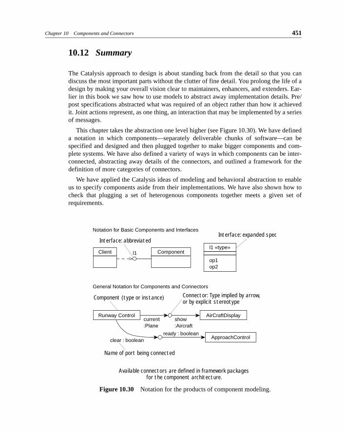
Chapter 10 Components and Connectors 451
10.12 Summary
The Catalysis approach to design is about standing back from the detail so that you candiscuss the most important parts without the clutter of fine detail. You prolong the life of adesign by making your overall vision clear to maintainers, enhancers, and extenders. Ear-lier in this book we saw how to use models to abstract away implementation details. Pre/post specifications abstracted what was required of an object rather than how it achievedit. Joint actions represent, as one thing, an interaction that may be implemented by a seriesof messages.
This chapter takes the abstraction one level higher (see Figure 10.30). We have defineda notation in which components—separately deliverable chunks of software—can bespecified and designed and then plugged together to make bigger components and com-plete systems. We have also defined a variety of ways in which components can be inter-connected, abstracting away details of the connectors, and outlined a framework for thedefinition of more categories of connectors.
We have applied the Catalysis ideas of modeling and behavioral abstraction to enableus to specify components aside from their implementations. We have also shown how tocheck that plugging a set of heterogenous components together meets a given set ofrequirements.
Figure 10.30 Notation for the products of component modeling.
Available connectors are defined in framework packagesfor the component architecture.
Interface: abbreviatedInterface: expanded spec
Client
Notation for Basic Components and Interfaces
Runway Control AirCraftDisplay
ApproachControl
Componentl1l1 «type»
op1op2
Component (type or instance)
Name of port being connected
Connector: Type implied by arrow,or by explicit stereotype
General Notation for Components and Connectors
current:Plane
show:Aircraft
ready : booleanclear : boolean

452 PART IV IMPLEMENTATION BY ASSEMBLY