chapter 10: gps instrumentation issues dorota … · the major purpose of this chapter it to...
TRANSCRIPT

Published in Manual of Geospatial Science and Technology, J. Bossler (Ed.), Taylor and Francis, 2002
CHAPTER 10: GPS INSTRUMENTATION ISSUES Dorota Grejner-Brzezinska The major purpose of this chapter it to briefly address important issues related to GPS instrumentation, such as receiver design and functionality, modes of operation, factors limiting GPS accuracy, auxiliary equipment used with GPS receivers, as well as data processing software. GPS instrumentation, especially the high quality, is rather expensive, thus for the user it is essential to understand the principal differences between different classes of the receivers, different performance and accuracy specifications, in order to make an educated choice of the GPS equipment and properly define the needs of a specific application. GPS instrumentation covers a broad selection of topics, and the scope of this book does not permit a comprehensive approach covering in depth all related issues. Thus, it is the author�s intention to briefly address the most important issues, referring the reader to a specialized literature existing on this topic. It is also beyond the scope of this chapter to provide the reader with a full list of GPS products and their manufacturers, especially that new receivers are continuously being developed. The best and most complete (according to the author) source of this information is GPS World Buyers Guide (usually in June edition), GPS World Receiver Survey (usually in January edition) and GPS World Showcase (special editions, usually August and December), featuring the technology and product innovations. The latest edition of the GPS World Buyers Guide is also available on the GPS World web page: http://www.gpsworld.com/. 10.1. GPS Signal Characteristics The purpose of this section is to briefly characterize the physical behavior of electromagnetic waves and the structure of the signal transmitted by GPS satellites, as well as to define related terminology and units, to help the reader understand the signal processing techniques inside the GPS receiver and the functionality of the GPS equipment. The GPS signal is more comprehensively treated in Chapter xx of this book. The signal generated by a GPS satellite oscillator contains three primary components: pure sinusoidal waves or carriers (L1, L21), precision or protected pseudorandom P(Y)-code (superimposed on L1 and L2 carriers) and coarse-acquisition pseudorandom C/A-code (superimposed on L1 carrier), and navigation message (on L1 and L2). All signals transmitted by GPS satellites are right-hand polarized2, coherently derived from a basic frequency of 10.23 MHz, as shown in Table 10.1, and are transmitted within a bandwidth of about 20.46 MHz3 (at both center frequencies) by a shaped-beam antenna array on the nadir-facing side of the satellite. The frequency separation between L1 and L2 is 347.82 MHz or 28.3%, and it is sufficient to permit accurate dual-frequency estimation of the ionospheric group delay. Each satellite transmits a unique C/A-code and a unique one-week long segment of P-code, reinitialized weekly at Saturday/Sunday midnight. The P-code is currently not
1 The GPS satellites also transmit an L3 signal at 1381.05 MHz (135×10.23 MHz), associated with their dual role as a nuclear burst detection satellite as well as S-band telemetry signal. 2 Polarization is a property of a single-frequency electromagnetic wave, describing the shape and orientation of the locus of the extremity of the field vectors as a function of time. In antenna engineering plane waves are of a primarily concern. For plane waves (or waves that are considered planar over a local region) polarization properties of the electric field vector have to be specified, as magnetic field vector is simply related to the electric field vector (Johnson, 1993). GPS signal is polarized with an ellipticity for L1 no worse than 1.2 dB (see footnote 5 below for a definition of dB) and 3.2 dB for L2 within an angular range of ±14.3° from boresight (perfectly circular polarization has an ellipticity of 0 dB). 3 A bandwidth of 20 MHz is required for the whole VHF (very high frequency) FM broadcast band.
Published in Manual of Geospatial Science and Technology, J. Bossler (Ed.), Taylor and Francis, 2002
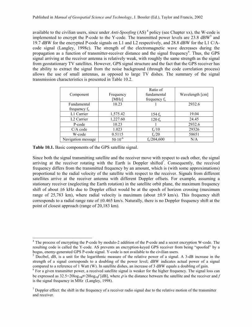
available to the civilian users, since under Anti-Spoofing (AS) 4 policy (see Chapter xx), the W-code is implemented to encrypt the P-code to the Y-code. The transmitted power levels are 23.8 dBW5 and 19.7 dBW for the encrypted P-code signals on L1 and L2 respectively, and 28.8 dBW for the L1 C/A-code signal (Langley, 1998c). The strength of the electromagnetic wave decreases during the propagation as a function of transmitter-receiver distance and the signal frequency6. Thus, the GPS signal arriving at the receiver antenna is relatively weak, with roughly the same strength as the signal from geostationary TV satellites. However, GPS signal structure and the fact that the GPS receiver has the ability to extract the signal from the noise background (through the code correlation process) allows the use of small antennas, as opposed to large TV dishes. The summary of the signal transmission characteristics is presented in Table 10.2.
Component
Frequency
[MHz]
Ratio of fundamental frequency fo
Wavelength [cm]
Fundamental frequency fo
10.23 1 2932.6
L1 Carrier 1,575.42 154⋅fo 19.04 L2 Carrier 1,227.60 120⋅fo 24.45
P-code 10.23 1 2932.6 C/A code 1.023 fo/10 29326 W-code 0.5115 fo/20 58651
Navigation message 50⋅10-6 fo/204,600 N/A
Table 10.1. Basic components of the GPS satellite signal. Since both the signal transmitting satellite and the receiver move with respect to each other, the signal arriving at the receiver rotating with the Earth is Doppler shifted7. Consequently, the received frequency differs from the transmitted frequency by an amount, which is (with some approximations) proportional to the radial velocity of the satellite with respect to the receiver. Signals from different satellites arrive at the receiver antenna with different Doppler offsets. For example, assuming a stationary receiver (neglecting the Earth rotation) in the satellite orbit plane, the maximum frequency shift of about ±6 kHz due to Doppler effect would be at the epoch of horizon crossing (maximum range of 25,783 km), where radial velocity is maximum (about ±0.9 km/s). This frequency shift corresponds to a radial range rate of ±0.465 km/s. Naturally, there is no Doppler frequency shift at the point of closest approach (range of 20,183 km). 4 The process of encrypting the P-code by modulo-2 addition of the P-code and a secret encryption W-code. The resulting code is called the Y-code. AS prevents an encryption-keyed GPS receiver from being �spoofed� by a bogus, enemy-generated GPS P-code signal. Y-code is not available to the civilian users. 5 Decibel, dB, is a unit for the logarithmic measure of the relative power of a signal. A 3-dB increase in the strength of a signal corresponds to a doubling of the power level; dBW indicates actual power of a signal compared to a reference of 1 Watt (W). In satellite dishes, an increase of 3 dBW equals a doubling of gain. 6 For a given transmitter power, a received satellite signal is weaker for the higher frequency. The signal loss can be expressed as 32.5+20log10ρ+20log10f [dB], where ρ is the distance between the satellite and the receiver and f is the signal frequency in MHz (Langley, 1998). 7 Doppler effect: the shift in the frequency of a receiver radio signal due to the relative motion of the transmitter and receiver.

Published in Manual of Geospatial Science and Technology, J. Bossler (Ed.), Taylor and Francis, 2002
Component C/A P (Y) Navigation data Chipping rate 1.023 Mbps (106 bits per
second) 10.23 Mbps 50 bps
Chip length 293 m 29.3 m 5950 km Repetition rate 1 ms 1 week N/A
Code type 37 unique codes (Gold code)
37 one-week segments (pseudorandom, PRN)
N/A
Carrier frequency L1 L1, L2 L1, L2 Expected minimum signal
strength at the user receiver, referenced to
0 dBic8 antenna9
-160 dBW
-163 dBW (on L1) -166 dBW (on L2)
N/A
Fundamental property
Easy to acquire due to its short period and low cross-correlation between the members of the family; thus easy to rapidly distinguish among signals arriving simultaneously from multiple satellites; acquired before P(Y) code; provides the timing and allows the access to the hand-over word (HOW) to acquire P(Y)-code
More accurate and jam resistant; not available to the civilian users; PRN sequence used as satellite ID (PRN 28 transmits 28-th portion of the PRN code); resistant to mutual interference when signals are received simultaneously from multiple satellites; difficult to acquire, i.e., receiver correlator must be timed to within roughly one P-code chip (or 0.1 µs) to correlate at all
Provides satellite health status, time, ephemeris, various correction terms and HOW, which tells the receiver where to start the search for P(Y) code. Total transmission time is 30 seconds.
Table 10.2. GPS signal characteristics. 10.2. GPS Receiver: Major Components GPS receivers belong of the GPS User Segment, which generally speaking, covers the entire spectrum of applications, equipment and computational techniques that are available to the systems� users. While GPS data processing techniques and applications are addressed in other sections of this book, this chapter will discuss only the instrumentation issues that are of a primary concern to the users. The receiver�s internal design and operational modules, performance consideration as well as some future trends in the receiver technology are addressed, with special emphasis on the practicality and application-oriented aspects. Over the past two decades the civilian as well as military GPS instrumentation evolved through several stages of design and implementation, focused primarily on achieving an enhanced reliability of positioning and timing, modularization and miniaturization. In addition, one of the most important aspects, especially for the civilian market, has been the cost decrease requirement, (which naturally should not compromise the performance), as the explosion of GPS applications calls for a variety of low-cost, application-oriented and reliable equipment. By far, the majority of the receivers manufactured today are of the C/A-code single frequency type. However, for the high precision geodetic applications the dual frequency solution is a standard. Even though the civilian and military
8 dBic describes antenna gain in dB with respect to a circularly polarized isotropic radiator (a hypothetical ideal reference antenna) 9 Signals are observed for elevation angles above 5° within the 20 MHz frequency allocation; 2.0 dB atmospheric loss was assumed (Parkinson and Spilker, 1996; Langley, 1998c)
Published in Manual of Geospatial Science and Technology, J. Bossler (Ed.), Taylor and Francis, 2002
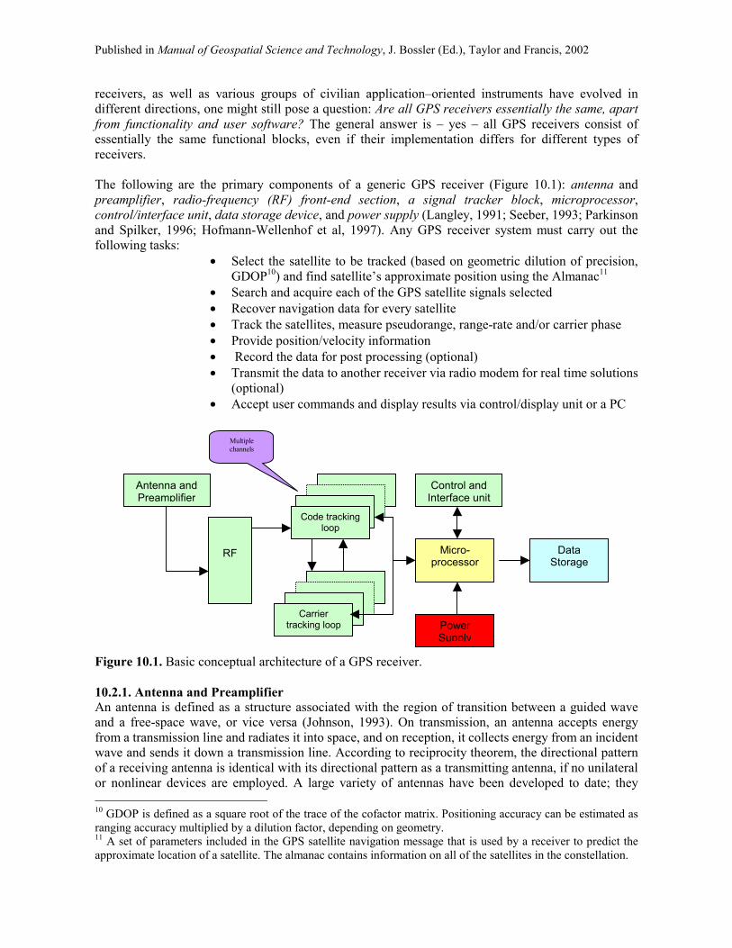
receivers, as well as various groups of civilian application�oriented instruments have evolved in different directions, one might still pose a question: Are all GPS receivers essentially the same, apart from functionality and user software? The general answer is � yes � all GPS receivers consist of essentially the same functional blocks, even if their implementation differs for different types of receivers. The following are the primary components of a generic GPS receiver (Figure 10.1): antenna and preamplifier, radio-frequency (RF) front-end section, a signal tracker block, microprocessor, control/interface unit, data storage device, and power supply (Langley, 1991; Seeber, 1993; Parkinson and Spilker, 1996; Hofmann-Wellenhof et al, 1997). Any GPS receiver system must carry out the following tasks:
• Select the satellite to be tracked (based on geometric dilution of precision, GDOP10) and find satellite�s approximate position using the Almanac11
• Search and acquire each of the GPS satellite signals selected • Recover navigation data for every satellite • Track the satellites, measure pseudorange, range-rate and/or carrier phase • Provide position/velocity information • Record the data for post processing (optional) • Transmit the data to another receiver via radio modem for real time solutions
(optional) • Accept user commands and display results via control/display unit or a PC
Figure 10.1. Basic conceptual architecture of a GPS receiver. 10.2.1. Antenna and Preamplifier An antenna is defined as a structure associated with the region of transition between a guided wave and a free-space wave, or vice versa (Johnson, 1993). On transmission, an antenna accepts energy from a transmission line and radiates it into space, and on reception, it collects energy from an incident wave and sends it down a transmission line. According to reciprocity theorem, the directional pattern of a receiving antenna is identical with its directional pattern as a transmitting antenna, if no unilateral or nonlinear devices are employed. A large variety of antennas have been developed to date; they 10 GDOP is defined as a square root of the trace of the cofactor matrix. Positioning accuracy can be estimated as ranging accuracy multiplied by a dilution factor, depending on geometry. 11 A set of parameters included in the GPS satellite navigation message that is used by a receiver to predict the approximate location of a satellite. The almanac contains information on all of the satellites in the constellation.
Antenna and Preamplifier
Control and Interface unit
Micro-processor
Power Supply
Data Storage
Code tracking loop
Carrier
tracking loop
RF
Multiple channels

Published in Manual of Geospatial Science and Technology, J. Bossler (Ed.), Taylor and Francis, 2002
range from simple structures such as monopoles and diapoles12 to complex phased arrays. The choice of the antenna for an application depends primarily on the electrical and mechanical requirements of the system used. The GPS receiving antenna detects an electromagnetic signal arriving from a satellite, and after a bandpass filtering, which provides adequate filter selectivity to attenuate adjacent channel interference, and initial preamplification (see Section 10.2.1.1), transfers the signal to the RF section for further processing by the receiver electronics. A typical GPS antenna is omnidirectional13 (azimuthal-plane), thus having essentially non-directional pattern in azimuth and a directional pattern in elevation angle. As the GPS signals are transmitted from the satellite with right-hand circular polarization, all GPS antennas must also be right-hand polarized14. Moreover, it is mandatory for a GPS antenna to maintain high sensitivity (high gain15) due to the relative weakness of the incoming signal. In general, antennas can be designed as L1-only or dual frequency, when both L1 and L2 carries are tracked. For geodetic, high-precision applications, additional ground plane or choke rings16 can be used primarily to mitigate multipath effects17. The most common GPS antenna types available presently on the market are monopole (asymmetric antennas) and diapole (symmetric antennas) configurations, quadrifilar helices18, spiral helices, and microstrips19, with the last design being the most popular, primarily due to a relatively easy implementation and miniaturization, ruggedness and suitable characteristics for kinematic applications. GPS antennas are often protected against possible damages by a plastic housing (radome), designed to minimize attenuation of the signal (Langley, 1995 and 1998c). 12 Monopole and dipole are thin wire antennas. Monopoles are, in general, 0.25 wavelength long and are mounted on a ground plane (with small separation). The center conductor of the coaxial is connected to the wire, whereas, the outer shield is connected to the ground plane. Dipoles, in general, are 0.5 wavelength long and consist of two equal wire segments, with the coaxial cable attached to both wire segments. 13 Omnidirectional radiation pattern is most popular in communication and broadcast applications. The azimuthal pattern is circular, but the elevation pattern has some directivity to increase the gain in the horizontal directions (Johnson, 1993). 14 The plane containing the electric and the magnetic fields is called plane of polarization, and it is orthogonal to the direction of propagation. The polarization of the wave is specified by the shape and orientation of the ellipse and the direction, in which the electric field vector traverses the ellipse. The shape of the ellipse is specified by its axial ratio � the ratio of the major axis to the minor axis. The direction, in which the electric field vector traverses the ellipse, is the sense of polarization � right-handed or left-handed when viewed in the direction of propagation (Johnson, 1993). A small value of the axial ratio indicates a properly balanced antenna gain pattern (see footnote 15 below), which allows for a high degree of polarization discrimination, i.e., the reflected signal (left-hand polarized) will be filtered, as the antenna will have a low sensitivity to the left-hand polarization. Good GPS antennas have an axial ratio in zenith direction of 2 dB or better (Langley, 1998a). 15 The antenna gain is a measure of the ability to concentrate in a particular direction the power accepted by the antenna (Johnson, 1993). Gain pattern describes change of the antenna sensitivity over some range of elevation and azimuth angles, or the ability to discriminate multipath signal and stability of the phase center (Langley, 19982). 16 Ground plane is a horizontally oriented metallic disk, centered at the GPS antenna�s base, which shield the antenna from any signals arriving from below the antenna. Choke ring is essentially a ground plane containing a series of concentric circular troughs one-quarter wavelength deep, designed to eliminate multipath surface waves (Figure 10.2). 17 Any signals other than the direct one from the satellite; signal reflected from the nearby objects. 18 A helical antenna consists of a single conductor or multiple conductors wound into a helical shape with circular or elliptical cross section. Generally helical antennas are wound with a single conductor, however, a helix can be designed with bifilar, quadrifilar or multifilar windings (Johnson, 1993). Quadrifilar helix antenna is frequently used with hand-held GPS receiver; it does not need a ground plane. 19 Microstrip antenna, also called a patch antenna, is usually constructed of one or more, elements that are photoetched on one side of double-coated, printed-circuit board. It can be circular or rectangular in shape, made up of one or more patches of metal, separated from a ground plane by a dielectric sheet. They may have single- or dual-frequency capability with usually narrow bandwidth (Langley, 1998a).

Published in Manual of Geospatial Science and Technology, J. Bossler (Ed.), Taylor and Francis, 2002
Figure 10.2. Micro-centered L1/L2 antenna with ground plane and L1/L2 choke ring antenna
(courtesy Trimble Navigation Ltd.) and RegAnt zero centered antenna mounted on single-depth choke ring or dual-depth choke ring in a fully weatherproof enclosure (courtesy Javad Positioning Systems).
10.2.1.1. Preamplifier Section Even though the power of extracting a weak GPS signal from the background noise is concentrated in the receiver rather than the antenna (see Section 10.1), most of GPS antennas are generally combined with a low-noise preamplifier (sometimes supported by additional filters either before or after the preamplifier). Antenna, combined with a preamplifier usually housed in the base of the antenna, between the output of the antenna and the feeder line to the receiver, is called an active antenna, as opposed to a passive antenna without a preamplifier. Preamplifier boosts the signal level before feeding it to the receiver�s RF front-end section. However, the amplifier has a beneficial effect only if its noise figure (usually 1-5 dB) is less than the feeder noise figure, and its gain (usually 10-40 dB) is much higher (Johnson, 1993). The gain needed by the preamplifier depends primarily on the gain of the antenna itself, antenna coaxial cable length, and the requirements of the receiver�s front end. Thus, special caution must be exercised when using an active antenna with a preamplifier not supported by the receiver manufacturer: preamplifiers noise and gain must be within the receiver�s acceptable range, as well as the voltage and current supplied by the receiver to the preamplifier must be compatible with the antenna�s characteristics. A total gain of active antennas ranges between 20 and 50 dB, while power consumption is between 12 and 32 mA at 5 V DC. A good GPS antenna should also have the capability of rejecting signals that are outside the GPS band, thus the amplifier section should contain separate quality filters for each of the L1 and L2 bands. An amplified antenna can lead to an increased accuracy by allowing tracking of maximum number of satellites in view, and can help prevail over the following problems (where passive antenna can totally fail):
• Losses of lock due to vehicle dynamics • Losses of lock under heavy foliage cover or other difficult areas • Tracking under obscured, not clear view of the sky
10.2.1.2. Cables and Connectors An important issue, which cannot be overlooked while choosing a GPS antenna, is proper selection of the antenna cable, as the signal attenuation depends on the type and the length of the cable used. This is especially important for passive antennas, which do not benefit from the extra gain provided by the preamplifiers. The signal power can be substantially lost if coupling between the antenna and the

Published in Manual of Geospatial Science and Technology, J. Bossler (Ed.), Taylor and Francis, 2002
receiver is flawed (due, for example, to different impedance20 of the connecting cable and the antenna) or the cable itself is not correct. Flexible RG/U coaxial transmission lines with 50-Ohm impedance (to match GPS antenna impedance), consisting of a solid or stranded inner conductor, a plastic-dielectric support, and a braided outer conductor, are most commonly used to connect GPS antenna with the receiver. Since signal loss increases linearly with a cable length (and is slightly higher for high frequencies), for long runs, it is recommended to use a low-loss cable (more expensive), such as Belden 9913 or 8214 with losses of 0.2 dB and 0.4 dB per meter at 1575 MHz, or RG-58C or RG-62 (or 62A) with losses of 0.8 dB and 0.3 dB per meter at 1575 MHz, respectively. Another way to minimize the signal attenuation on the long cable is to place an additional preamplifier between the antenna and the cable. For short runs, however, cheaper RG-174 or Belden 9201 with losses of 2 dB and 1 dB per meter, respectively, would be sufficient. A variety of connectors used to connect the antenna cables with antennas and receivers are used for GPS equipment. The most commonly used types (in both male and female varieties) are: BNC, F, MCX, N-type, OSX, SMA, SMB and TNC (Langley, 1998a). Thus, when buying a GPS receiver, the user should pay a close attention to the types of connectors required at both ends. A full list and the characteristics of flexible coaxial lines RG/U type and frequently used connectors are provided by Johnson (1993) and http://www.stormproducts.com/. 10.2.1.3 Antenna Characteristics Antenna Phase Center In the antennas typically used for GPS data collection the physical (geometric) center of the antenna usually does not coincide with the phase center (the electrical center) of the antenna � a point, to which radio signal measurements are referred. Moreover, the phase centers for L1 and L2 generally do not coincide, and naturally, different types of antennas have different location of their phase centers. A simple rule-of-thumb is to always align the properly leveled antennas in the same direction (local North), which results in cancellation in both length and orientation of the offset between physical and phase centers, when the same type of antenna is used at both ends of a short baseline. For longer baselines, where local verticals can no longer be assumed parallel, as well as for mixed types of antennas, this effect would generally not cancelled out. In this case, a phase center location has to be a part of the data reduction process, as the amount of the phase center offset is known and provided by the antenna manufacturer. However, the location of the phase center can vary with variable azimuth and elevation of the satellites and the intensity of the incoming signal. This effect should not, in general, exceed 1-2 cm, and for modern microstrip antennas it reaches only a few millimeters. Since GPS signal arrives at the phase center (L1 or L2), but most of the time the coordinates of the ground mark are sought, the observations have to be mathematically reduced to the ground mark location, using the antenna height. GSP antenna is usually mounted on a tribrach attached to a tripod, and oriented along the local plumb line directly above the ground mark to be surveyed. The antenna height is defined as a vertical distance between the ground mark and the antenna phase center. Usually, the slant height is measured to the bottom of the ground plane or the base of the choke rings, 20 Impedance � antenna�s opposition to current flowing in it. Combines antenna�s resistance to current and its reactance due to antenna�s capacitance or inductance, which affect the current flow. It can be expressed as a complex number, where the real part represents resistance and the imaginary one the reactance. The relationship between impedance and the voltage and current in the antenna or any circuit element is represented by the extension of Ohm�s law to alternating current: it is the ratio of the voltage to the current, measured in Ohms. Typical impedance of GPS antennas is 50 Ohms. Antennas and connecting cables must have the same impedance. If they are different, signal reflections may occur, giving rise to standing waves in the cable (Langley, 1998a). Standing waves are formed by superposition of waves of the same frequency traveling in opposite directions; VSWR (Voltage Standing Wave Ratio) is a measure of the efficiency of a signal interface, especially the impedance match of the antenna to the LNA (low noise amplifier).

Published in Manual of Geospatial Science and Technology, J. Bossler (Ed.), Taylor and Francis, 2002
and the vertical height is computed using manufacturer-provided information about phase center location (L1 and L2) above the reference planes, such as antenna base or bottom (top) of the ground plane. Antenna Gain Pattern Another important factor, which has to be taken into account while choosing the antenna for a specific application, is the antenna gain pattern. The measure of the antenna gain change over some range of elevations and azimuths is called the gain pattern, while gain refers to antenna�s ability to successfully receive a weak signal, or ability to concentrate in a particular direction the power accepted by the antenna. GPS antennas have usually +3 to +5 dBic gain at zenith, dropping down to about �1 dBic at 10° elevation and �10 dBic at 0°. Gain pattern, similarly to the phase center location, changes with the direction of the incoming signal. Since the antenna design must satisfy several, at times, conflicting goals, the common sense approach of uniform gain in all directions is not necessarily the best for GPS antenna. For example, low elevations have to be filtered, since too much gain in low elevation will contribute to high multipath and atmospheric signal attenuation. At the same time too much filtering at lower elevations would limit the minimum elevation, at which the satellite can be observed, resulting in weaker geometry. These have to be properly balanced during the antenna design process. Antenna Bandwidth Antenna bandwidth is defined as frequency band, over which the antenna�s performance (described in terms of gain pattern, polarization, input impedance, etc.) is sufficiently good (Langley, 1998a). Antennas may be narrow- or wideband. Since GPS is a narrowband system (within a bandwidth of about 20 MHz; see Section 10.1), most of GPS antennas are also of a narrowband type, to prevent from accepting interfering signals on adjacent frequencies (the wider the bandwidth, the more interfering signal is received rendering small signal-to-noise ratio, SNR21). On the other hand, bandwidth has to be large enough to assure antenna�s proper functioning over the intended range of frequencies. The bandwidth of microstrip antennas is proportional to the thickness of the substrate used (and the second power of frequency in GHz), and since most of them are very thin in terms of wavelength, their bandwidth is usually narrow. GPS microstrip antennas have bandwidth between 2 and 20 MHz, depending on the type of code signal they use. For example, antennas accepting only a central lobe22 of C/A-code might have very narrow bandwidth of ±2 MHz, while antennas using more than the central lobe of C/A-code or using P(Y)-code have wider bandwidth of ±10 to ±20 MHz. Dual frequency L1/L2 microstrip antennas are usually designed as two-patch antennas, one patch for each frequency, with bandwidth of ±10 to ±20 MHz each. 10.2.1.4. The Antenna for a Job The size and physical characteristics, which can be different depending on the application requirements, represent additional aspects affecting the antenna choice. For example, surveying (geodetic) antennas are usually much bigger, and have ground plane or choke rings added, as compared to compact, light-weighted kinematic antennas, especially for airborne applications. It is worthwhile to mention here that for some antennas, such as microistrip, a ground plane not only contributes to the multipath mitigation, but also increase the antenna�s zenith gain (to a certain size of the ground plane the larger the ground plane, the higher the antenna� zenith gain). As a matter of fact, microstrip antennas require a ground plane to make them work properly (Langley, 1998a and c). Airborne antennas, for example, should have a capability of acquiring a signal from below the antenna horizon, which is naturally not a feature that one would expect carrying out a high quality, land-based 21 SNR is defined as a ratio of the received signal�s power, S, and the noise power, N, measured at the same time and place in a circuit, made on signal at band occupied by the signal after demodulation. 22 Transmitted C/A-code is nearly unfiltered and contains side lobes out to the 10th. The P-code has the same bandwidth but 10 times the clock rate, and thus only contains the main lobe.

Published in Manual of Geospatial Science and Technology, J. Bossler (Ed.), Taylor and Francis, 2002
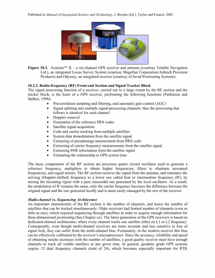
geodetic application. Moreover, majority of hand-held GPS receivers have a very small, predominantly single-frequency antenna, embedded in the receiver, while surveying antennas are usually dual frequency, especially where cm-level or better accuracy is expected. The antennas for hand-held receivers are usually the quadrifilar helices, consisting of two bifilar helical loops, orthogonally oriented on a common axis, which do not require a ground plane (as opposed to microstrips used for surveying-type antennas). Smart Antennas/Integrated Receivers For applications such as tracking weather buoys, time tagging of seismic or other events, navigation, or precise timing and synchronization of wireless voice and data networks, so called smart antennas are often used (e.g. Acutime II from Trimble Navigation Ltd.). A smart antenna, a self-contained, shielded and sealed unit with digital interface, houses a GPS receiver, an antenna, a power supply, and other supporting circuitry in a single ruggedized enclosure, which mounts like an antenna (Figure 10.3). Once power is applied, a smart antenna operates automatically and provides position, course, speed and time over the serial interface port. In addition to serial data, a second serial port enabling differential GPS (DGPS) operation (see Section 10.3), and an accurate timing pulse (1pps signal) synchronized to UTC to 1 microsecond can also be provided. Smart antennas have evolved further into a comprehensive survey packages (e.g. Locus Survey System from Magellan Corporation/Ashtech Precision Products (Figure 10.3)), or fully integrated GPS receivers, such as Odyssey or Regency from Javad Positioning Systems (Figure 10.3). An integrated receiver, such as Odyssey houses electronic board with all its associated features, which also includes Spread Spectrum radio modem receiver (see Section 10.3) and transmitter, zero-centered antenna on a flat ground plane, half-wavelength Spread Spectrum radio antenna, removable radio receiver module, removable Lithium Ion battery module, and detachable interface. Smart antennas and integrated receivers provide easy to use, cable-free, light-weighted and low-power (2-3 W even for 20-channel version) high-accuracy and high-productivity option for traditional survey jobs. A question that seems to be quite appropriate to ask, concluding this section, is: Is there an ideal GPS antenna, or there is always some trade-off to consider? The answer, as the reader should expect, is � there is no ideal GPS antenna that is suitable for all types of GPS work. Each user must define the �best� based on the application-specific requirements, keeping in mind that each antenna type has a character of its own, and even these that appear to be physically similar might have quite substantially different performance characteristics (two different choke ring antennas from different manufacturers will most probably show significant differences in their properties). Once again, this issue becomes of a crucial importance when the highest accuracy is expected. For example, an antenna that provides a low elevation angle gain cutoff might not be the best to meet the requirements of low phase variation with zenith angle, and vice versa. Since most multipath arrives from the angles near the horizon, multipath may be rejected by shaping the pattern to have low gain in these directions, as explained above. This design, rendering a high profile antenna with a low gain in the horizon is particularly suitable for ground reference station. However, for airborne user the high profile antenna is not desirable for the following reasons: first, an extensive shaping pattern usually requires either large aperture or multiple elements and signal processing � thus due to the antenna size an additional drag is induced on the aircraft. Second, airborne antennas must still receive the signal while undergoing dynamics, while sharp null in the gain pattern might cause a signal loss. Consequently, the most popular airborne design is a light-weigh, small size microstrip antenna. An interested reader is referred to the Antenna Engineering Handbook by Johnson (1993), Schupler and Clark (1991), Weill (1997), and Langley (1998a and c) for more information about antennas.
Published in Manual of Geospatial Science and Technology, J. Bossler (Ed.), Taylor and Francis, 2002
Figure 10.3. Acutime II � a six-channel GPS receiver and antenna (courtesy Trimble Navigation
Ltd.), an integrated Locus Survey System (courtesy Magellan Corporation/Ashtech Precision Products) and Odyssey, an integrated receiver (courtesy of Javad Positioning Systems).
10.2.2. Radio-frequency (RF) Front-end Section and Signal Tracker Block The signal processing function of a receiver, carried out to a large extent by the RF section and the tracker block, is the heart of a GPS receiver, performing the following functions (Parkinson and Spilker, 1996):
• Precorrelation sampling and filtering, and automatic gain control (AGC) • Signal splitting into multiple signal-processing channels: thus the processing that
follows is identical for each channel • Doppler removal • Generation of the reference PRN codes • Satellite signal acquisition • Code and carrier tracking from multiple satellites • System data demodulation from the satellite signal • Extracting of pseudorange measurement from PRN code • Extracting of carrier frequency measurements from the satellite signal • Extracting SNR information from the satellite signal • Estimating the relationship to GPS system time
The basic components of the RF section are precision quartz crystal oscillator used to generate a reference frequency, multipliers to obtain higher frequencies, filters to eliminate unwanted frequencies, and signal mixers. The RF section receives the signal from the antenna, and translates the arriving (Doppler-shifted) frequency to a lower one called beat or intermediate frequency (IF), by mixing the incoming signal with a pure sinusoidal one generated by the local oscillator. As a result, the modulation of IF remains the same, only the carrier frequency becomes the difference between the original signal and the one generated locally and is more easily managed by the rest of the receiver. Multi-channel vs. Sequencing Architecture An important characteristic of the RF section is the number of channels, and hence the number of satellites that can be tracked simultaneously. Older receivers had limited number of channels (even as little as one), which required sequencing through satellites in order to acquire enough information for three-dimensional positioning (See Chapter xx). The latest generation of the GPS receivers is based on dedicated-channel architecture, where every channel tracks one satellite either on L1 or L2 frequency. Consequently, even though multi-channel receivers are more accurate and less sensitive to loss of signal lock, they can suffer from the multi-channel bias. Fortunately, in the modern receiver this bias can be effectively calibrated by the receiver�s microprocessor. Since the accuracy, reliability and speed of obtaining results increases with the number of satellites, a good quality receiver must have enough channels to track all visible satellites at any given time. In general, geodetic grade GPS systems require 12 dual frequency channels (total of 24), which becomes especially important for RTK

Published in Manual of Geospatial Science and Technology, J. Bossler (Ed.), Taylor and Francis, 2002
applications, where observability of more than 9 satellites can significantly increase the quality of the results. Receivers with single sequencing or multiplexing (fast rate sequencing) channel are less expensive as compared to the dedicated channel receiver, however, they are much slower, and thus not recommended for kinematic (especially high speed) applications. The IF signal produced by the RF section, in either sequencing or multi-channel mode, is subsequently processed by the signal tracking loops. Tracking Loops A tracking loop is a mechanism that enables a receiver to track a signal that is changing in frequency or in time. In principle, a tracking loop performs a comparison between the incoming signal and the local one generated in the receiver, and adjusts the internal signal to match the external one, arriving from a satellite. There are essentially two types of tracking loops used in GPS receivers, delay-lock (or code-tracking) loop (DLL) and the phase-lock (or carrier) tracking loop (PLL). Each channel of the RF section is connected to separate code tracking and carrier tracking loops that operate based on the mutual support and interaction, as shown in Figure 10.4. Dual frequency receivers have separate channels (and thus separate tracking loops) for both frequencies. A tracking loop must be tunable within a frequency range (i.e., must have sufficient bandwidth) to accommodate the residual frequency offset of the modulated signal caused by a Doppler shifts (maximum ±6 kHz), residual user clock drift, bias frequency offset, and data modulation. Residual Doppler shift, generally the dominant requirement on the IF bandwidth, can eventually be removed by some form of automatic frequency control signal processing, or as a part of the acquisition and tracking process23 (Parkinson and Spilker, 1996). Signal Acquisition with DLL and PLL The delay lock loop applies a code correlation technique to align a PRN code (either P or C/A) from the incoming signal with its replica generated in the receiver. The alignment is achieved by shifting the internal signal in time. In principle, the amount of shift that is applied corresponds to the time required for the incoming signal to travel from the satellite to the receiver. This time interval multiplied by the speed of light renders the range (or pseudo-range, affected by the lack of synchronization between the receiver and satellite clocks and atmospheric effects) between the phase centers of the receiver and the GPS satellite antennas. Normally, the short C/A-code (see Table 10.2) is acquired first, allowing an access to the navigation message. The timing information contained in the HOW word from the navigation message is subsequently used to lock to the P code. Once the delay-lock loop is locked, the PRN code is removed from the signal, by first, mixing it with the locally generated signal, and secondly, by applying filtering to narrow the resulting bandwidth down to about 100 Hz. Through this process the GPS receiver reaches the necessary SNR to compensate the gain limitations of a physically small antenna (Langley, 1991). At this point, the navigation data can be extracted (high-pass filtered) from the IF signal by the phase-lock loop, which performs the alignment of the phase of the beat frequency signal with the phase of the locally generated carrier replica. Once the oscillator is aligned with the IF signal (or locked to the signal), it will continue tracking the variations in the phase of the incoming carrier as the satellite-receiver range changes. Following Langley (1991), the carrier beat phase observable (in cycles) is obtained by counting the elapsed cycles and by measuring the fractional phase of the locked local oscillator signal. Naturally, the initial integer number of cycles is unknown, and should be found by a suitable ambiguity resolution procedure, as explained in Chapter xx.
23 The initial IF bandwidth can be, for example, set rather wide (5-10 kHz range) to accommodate the full Doppler shift uncertainty. After a search, signal acquisition, and automatic frequency control tracking, the IF bandwidth can be adaptively reduced to a smaller number (Parkinson and Spilker, 1996).

Published in Manual of Geospatial Science and Technology, J. Bossler (Ed.), Taylor and Francis, 2002
Figure 10.4. Interaction between delay lock and carrier tracking loops24. Signal Tracking in Presence of Anti-spoofing The code correlation tracking procedure explained above works well when the receiver has a full access to the PRN code. However, under Anti-Spoofing, which is the current mode of GPS operation, when the P-code is replaced with the encrypted Y-code, somewhat different tracking techniques must be applied (in civilian receivers) to gain an access to the observable on L2 frequency (remember, there is no C/A code on L2!). Thus, AS is the reason why L2 measurement is harder to make than L1. To battle the P-code encryption, codeless squaring, cross correlation and quasi-codeless tracking techniques were developed. It should be mentioned, however, that all these methods of recovering L2 carrier in presence of AS, show SNR degradation with respect to the code correlation technique, applicable under no-AS conditions (Table 10.3). Consequently, the weaker signal (indicated by smaller SNR) recovered under AS is more susceptible to jamming (interference) as well as the ionospheric scintillations.
1. Codeless squaring technique applies the autocorrelation of the incoming L2 signal, which results in un-modulated carrier with twice the carrier frequency. As a result of multiplying the signal by itself, the PRN modulation and navigation message are lost; moreover, the ambiguity resolution problem becomes more difficult for the signal with halved wavelength.
2. Cross-correlating L1 and L2 signal provides the difference between the carrier phases and ranges. In this case, the ambiguities can be resolved at difference frequency (so called widelane), whose wavelengths is 4.52 times that of L1 frequency, which naturally tremendously decreases the ambiguity search volume.
3. Code correlation combined with squaring correlates the Y-code on L2 with the locally generated replica of the P-code25, followed by low-pass filtering and squaring to remove the code modulation. This technique provides code range signal and half-wavelength carrier phase on L2.
4. Z-tracking is based on a separate correlation of the Y-code on both L1 and L2 frequencies with a locally generated replica of the P-code. Since the carries on both frequencies contain the encrypted code, the signal integration (performed by low-pass filtering) that follows the correlation process allows for estimation of the encrypting signal bit for each frequency, which is subsequently fed to the other frequency. According to Ashjaee (1993) �this estimation is used to remove the encrypting code from the signal.� The removal of the
24 The assumption here is that the Y-code is known, or there is no AS, and the P-code is directly accessible. 25 This correlation is possible because the Y-code originates from modulo-2 sum of the P-code and the encrypting W-code. Since the chipping rates of the W-code and the Y-code are at the ratio of 1/20 , there always exists Y-code portion, which is identical to the original P-code portions. Thus, the replica of the P-code is shifted to match with the underlying P-code portion of the satellite�s Y-code (Hofmann-Wellenhof et al, 1997).
Signal from RF section
Delay tracking
C/A-code Acquisition
P-code Acquisition
Coherent Navigation Data Demodulation and Carrier Recovery
Code Removal
Delay Estimate
Carrier Phase
Estimate

Published in Manual of Geospatial Science and Technology, J. Bossler (Ed.), Taylor and Francis, 2002
encrypting code allows to access the observable as in the case of no AS, thus code ranges and full wavelength L1 and L2 carrier phases are obtained.
Component
Squaring technique
Cross correlation Code correlation
plus squaring Z-tracking
L1 C/A code No Yes Yes Yes Y2 code No Y2-Y1 Yes Yes
L2 wavelength Half Full Half Full SNR -16 dB -13 dB -3 dB 0 dB
SNR degradation with respect to code correlation (no AS)
-30 dB
-27 dB
-17 dB
-14 dB
Table 10.3. L2 signal recovery under AS (Ashjaee and Lorenz, 1992). 10.2.3. Microprocessor, Internal Software and Command and Display Unit GPS receivers perform numerous operations in real-time, such as acquiring and tracking of the satellite signal, decoding the broadcast message, timekeeping, range data processing for navigation, multipath and interference mitigation, etc. All these operations are coordinated and controlled by a microprocessor and its internal software that contains instructions for running the receiver. Other functions that might be performed by the microprocessor are data filtering to reduce the noise, position estimation, datum conversion, interactive communication with the user via the control and display unit, and managing the data flow through the receiver�s communication port. The control device, usually designed as keypad display unit, is used to input commands from the user for selecting different data acquisition options (static, kinematic, etc.) and the important parameters (such as cut-off elevation, data interval, input the antenna height, etc.) as well as to display the information about the receiver�s operations, navigation results, observed GPS constellation, etc. Most receivers have command/display capabilities with extensive menus and prompting instructions, often times offering even on-line help. GPS receivers designed for integration into navigation systems usually do not have their own interface units; in such cases the communication with the receiver is facilitated through an on-board PC. 10.2.4. Data Storage, Output and Power Supply Many GPS receivers, primarily surveying type and those designed for differential positioning, provide a user with an option of storing the data and the navigation message for post-processing. The storage media most frequently used in GPS receivers are internal microchips, removable memory cards or solid state (RAM) memory, with the last one being the most popular in the modern receivers. The question: What are some of the memory considerations for GPS receivers? can be easily answered by the reader, who has to define the need depending on the project specifications. Manufacturers usually offer different memory options, and in case of extended storage requirements, an extra memory can always be added. The storage capacity that the user needs, depends on the length of the data acquisition session, type of observable to be recorded, number of channels, and the data interval (usually 1-20 Hz for surveying/geodetic receivers). A complete dual-frequency satellite data take about 100 bytes per epoch; multiplying this by the number of channels (maximum number of satellites to be observed) and total number of epochs of observation allows for estimation of the total memory needed. For example: recording data every 10 seconds for 10 hours with 10 satellites in view will require 360*10*10*100=3.6 Mbytes of data storage. Receivers storing data internally must have an RS-232 or some other kind of communication port (e.g. a fast parallel port), which enables communication and data transfer between (both ways) the receiver and a PC. For example, transferring data to a PC via serial port takes about 100 s per Mbyte of data

Published in Manual of Geospatial Science and Technology, J. Bossler (Ed.), Taylor and Francis, 2002
(thus 16 Mbytes of data takes little less than half an hour). Some of the modern receivers use fast parallel ports, which significantly reduce the data transfer time to about 30 s for 16 Mbytes of data in the example above (http://www.javad.com/). An alternative is to use a PCMCIA card and a PC with a PCMCIA card reader. Most of the presently manufactured GPS instrumentation is energy efficient and use low voltage DC power coming either from the internal rechargeable NiCd batteries, or external batteries such as Lithium Ion battery or Sealed Lead Acid batteries (see Table 10.4), allowing usually for several hour of continuous operation. External power can also be supplied to a GPS receiver via an AC-to-DC converter. The lower the power consumption of the receiver, the more survey time can be achieved from a single battery, and the less heavy load on the user going to the filed. Moreover, lower power consumption also increases the life span of the electronics. Typical power consumption for geodetic grade GPS receivers ranges from 2 to 9 W.
Characteristic NiCd Lithium Ion Sealed Lead Acid (SLA) Energy density [Wh/kg] 40-60 100 30
Cycle life 1500 Up to 1000 2-year life time
200-300
Fast charge time 1-1.5 h 3-4 h 8-16 h Overcharge tolerance Moderate Very low High
Self-discharge per month
20% 10% 5%
Nominal cell voltage 1.2 V 3.6 V 2 V Maintenance requirement
30-60 days Not required 3-6 months
Size/weight Small for portable equipment
Small Typically large
Typical cost in US$ $50 (7.5 V) $100 (7.2 V) $25 (6 V)
Other characteristics
- Recommended slow charge of a new battery for 24 h - Performs best if fully discharged periodically - Sheer endurance - High current capabilities - The only commercial battery that accepts charge in extremely low temperatures
- Does not need periodic full discharges - Lightest of all batteries - May cause thermal run-away - Usually sold in a pack, complete with a protection circuit - Non-rechargeable version available - Most expensive
- Good storage life but can never be recharged to its full potential - Should be stored in charged state - Most economic for high-power applications where size and weight is not a consideration
Table 10.4. Batteries most commonly used for GPS equipment (source: http://www.cadex.com). 10.3. Auxiliary Equipment for Real-time Operation Traditionally, in geodesy and surveying the data are collected over fixed, temporarily or permanently monumented points, and stored for the post-mission processing. In many cases, however, such as navigation, intelligent transportation systems (ITS), or growing in popularity mobile mapping, the position of the moving vehicle has to be determined in real time. Moreover, real-time capability can increase productivity up to 100% for surveying jobs such as topographic contouring, staking out, laying down a new road, etc. Depending on the accuracy requirements, two basic modes of real time operation can be used: differential GPS (or DGPS) or real time kinematic (RTK). DGPS entails a reference station transmitting pseudorange correction to the users, whose receivers use this information together with their pseudoranges to produce a sub-meter accuracy positioning. RTK, on the other hand, is based on transmitting base station carrier phase data to the users� receivers, permitting real-time, high accuracy positioning. In order to facilitate easy and uniform data transfer to

Published in Manual of Geospatial Science and Technology, J. Bossler (Ed.), Taylor and Francis, 2002
the users equipped with appropriate equipment, the Radio Technical Commission for Maritime Services (RTCM) established a standard format for DGPS correction (in 1985) and RTK carrier phase (in 1994) data transmission. Although other proprietary formats have been devised, the RTCM format remains the most widely used. 10.3.1. Differential GPS (DGPS) Naturally, all real-time applications always involve some type of wireless transmission system. It may employ VHF26 or UHF27 systems for short ranges, low frequency transmitters for medium ranges (beacons) and L-band or C-band geostationary satellites for coverage of entire continents (WADGPS, Wide Area DGPS such as OmniSTAR). DGPS usually involves one or more GPS base stations that track all the satellites in view and, based on their precisely known locations and satellite broadcast ephemeris, estimate the errors in the GPS pseudo-ranges due to the Selective Availability (SA)28 and other errors including atmospheric delay. This information is used to generate pseudorange corrections that are subsequently sent to the master control station, which uploads checked and weighted corrections to the communication satellite. Since atmospheric correction is estimated for base station location it has to be automatically optimized for each user's location by the internal software of the GPS/DGPS user set, such as OmniSTAR (Figure 10.5). Based on the user�s approximated location (from the GPS receiver), an internal model is used to compute and remove most of the atmospheric correction contained in the range correction, and substitute a correction for user�s own location. The next step is to use an inverse distance-weighted least-squares solution (user�s location against all the base stations) to optimize the total range correction for user�s location; this technique is called a Virtual Base Station Solution. An alternative hardware configuration is a stand-alone OmniSTAR receiver connected to a stand-alone GPS receiver. In that case, the user's receiver must have an output message in one of the approved formats (NMEA 018329) and protocols that OmniSTAR can recognize (for example 12-channel Trimble receiver Pathfinder Pro XRS for GIS data collection). That output can be connected back to the OmniSTAR by using the same cable that normally supplies the RTCM-104 from OmniSTAR to the user's GPS receiver, providing the same functionality as OmniSTAR GPS/DGPS set (for equipment, service subscription prices, terms and conditions, see http://www.omnistar.com/). In addition to the range correction, a range-rate term in meters per second is also generated, which allows continuous data correction at the user�s end, while waiting for a new message. Naturally, the quality of the range-rate prediction determines the error growth in the corrected data during the time between two consecutive messages. For example, OmniSTAR allows 12 seconds before the error from the range-rate term will cause a meter level error in the corrected pseudorange; since a new 26 Very High Frequency 27 Ultra High Frequency 28 The Department of Defense policy and procedure of denying to most non-military GPS users the full accuracy of the system. SA is achieved by dithering the satellite clock (delta process) and degrading the navigation message ephemeris (epsilon process). Currently, SA primarily uses the delta process. The effects can be removed with encryption keys or through DGPS techniques. 29 NMEA, National Marine Electronics Association, professional trade association, serving all segments of the marine marketplace, including development of the only uniform interface standard for digital data exchange between different marine electronic devices, navigation equipment and communication equipment, NMEA 0183. NMEA 0183 data transmissions use plain text in ASCII (American Standard Code for Information Exchange) format. The data are transmitted in serial, asynchronous form (serial means that bits are sent one at a time with one bit following the next). Among currently approved 60 NMEA sentence types, nine are specific to GPS receivers: ALM � GPS almanac data, GBS � GPS satellite fault detection, GGA � GPS fix data, GRS � GPS range residuals, GSA � GPS DOP (dilution of precision) and active satellites, GST � GPS pseudorange noise statistics, GSV � GPS satellite in view, MSK � MSK (minimum-shift keying) receiver/GPS receiver interface, MSS � MSK receiver signal status (Langley, 1995b).

Published in Manual of Geospatial Science and Technology, J. Bossler (Ed.), Taylor and Francis, 2002
message is sent every two and a half seconds, even if a user misses an occasional message, the �age of data� is still within the 12 seconds range. This allows the user to take his GPS and communication equipment anywhere within the coverage area and get consistent accuracy results.
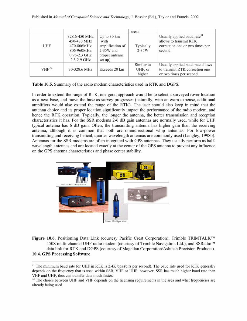
Figure 10.5. OmniSTAR 3000L DGPS (courtesy of OmniSTAR) 10.3.2. Real Time Kinematic (RTK) GPS In RTK positioning, a GPS reference (base) station transmits carrier phase and pseudorange data over a radio link to a roving receiver. Usually identical, single or dual frequency receivers are used, with a dual frequency system typically facilitating faster ambiguity resolution and higher positioning accuracies, especially over long baselines. Since RTK is predominantly based on the radio connection, the speed of the radio link is the limiting factor for sending the data from the base to the rover, while the amplification power available at the base determines the effective range of RTK. While RTK data processing algorithms including ambiguity resolution on-the-fly are proven and effective techniques (even under AS and SA), the quality and reliability of radio link, determine in fact the effectiveness and success of RTK. Some choices that the users have selecting the radio modems (Figure 10.6) are summarized in Table 10.5.
Component
Frequency allocation in the
United Sates
Range [km]
Amplifiers
Special Characteristics
Spread Spectrum Radio30 (SSR)
902-928 MHz, 2.4-2.4835 GHz
5.725-5.850 GHz
1.5 km with embedded 50 mW amplifier
1W (max allowable) extends the range to 20 km in open
Considered the most advanced and most reliable radio modem for RTK and DGPS; rover can receive data 6 times faster that in case of UHF and VHF
30 Spread Spectrum Radio was almost exclusively used by military until 1985, when FCC allowed spread spectrum�s unlicensed commercial use in three frequency bands: 902-928 MHz, 2.4-2.4835 GHz and 5.725-5.850 GHz. SSR differs from other commercial radio technologies because it spreads, rather than concentrates, its signal over a wide frequency range within its assigned bands. A key characteristic of spread spectrum radios is that they increase the bandwidth of the transmitted signal by a significantly large ratio to the original signal bandwidth. The main signal-spreading techniques are direct sequencing and frequency-hopping. Direct sequencing continuously distributes the data signal across a broad portion of the frequency band; it modulates a carrier by a digital code with a bit rate much higher than the information signal bandwidth. Alternatively, frequency-hopping radios move a radio signal from frequency to frequency in a fraction of a second. The spread spectrum receiver has to reconstruct the original modulating signal from the spread-bandwidth signal by a process called correlation (or de-spreading). The fact that the interference remains spread across a large bandwidth allows the receiver to filter out most of their signal energy, by selectively allowing through only the bandwidth needed for the de-spread wanted signal. Thus, the interference is reduced by SSR processing. Transmitting and receiving SSR radios must use the same spreading code, so only they can decode the true signal.
Published in Manual of Geospatial Science and Technology, J. Bossler (Ed.), Taylor and Francis, 2002
areas
UHF
328.6-450 MHz 450-470 MHz 470-806MHz 806-960MHz 0.96-2.3 GHz 2.3-2.9 GHz
Up to 30 km (with amplification of 2-35W and proper antenna set up)
Typically 2-35W
Usually applied baud rate31 allows to transmit RTK correction one or two times per second
VHF,32
30-328.6 MHz
Exceeds 20 km
Similar to UHF, or higher
Usually applied baud rate allows to transmit RTK correction one or two times per second
Table 10.5. Summary of the radio modem characteristics used in RTK and DGPS. In order to extend the range of RTK, one good approach would be to select a surveyed rover location as a next base, and move the base as survey progresses (naturally, with an extra expense, additional amplifiers would also extend the range of the RTK). The user should also keep in mind that the antenna choice and its proper location significantly impact the performance of the radio modem, and hence the RTK operation. Typically, the longer the antenna, the better transmission and reception characteristics it has. For the SSR modems 2-6 dB gain antennas are normally used, while for UHF typical antenna has 6 dB gain. Often, the transmitting antenna has higher gain than the receiving antenna, although it is common that both are omnidirectional whip antennas. For low-power transmitting and receiving helical, quarter-wavelength antennas are commonly used (Langley, 1998b). Antennas for the SSR modems are often integrated with GPS antennas. They usually perform as half-wavelength antennas and are located exactly at the center of the GPS antenna to prevent any influence on the GPS antenna characteristics and phase center stability. Figure 10.6. Positioning Data Link (courtesy Pacific Crest Corporation); Trimble TRIMTALK�
450S multi-channel UHF radio modem (courtesy of Trimble Navigation Ltd.), and SSRadio data link for RTK and DGPS (courtesy of Magellan Corporation/Ashtech Precision Products).
10.4. GPS Processing Software 31 The minimum baud rate for UHF in RTK is 2.4K bps (bits per second). The baud rate used for RTK generally depends on the frequency that is used within SSR, VHF or UHF; however, SSR has much higher baud rate than VHF and UHF, thus can transfer data much faster. 32 The choice between UHF and VHF depends on the licensing requirements in the area and what frequencies are already being used

Published in Manual of Geospatial Science and Technology, J. Bossler (Ed.), Taylor and Francis, 2002
Selection of GPS processing software is as important as the choice of the receiver itself as the type of data processing algorithms and their implementation may impact the overall GPS accuracy. Thus it is crucial to fully understand the software�s capabilities and ways to achieve the highest performance, as well as interpret the results properly. Data processing performed under incorrect assumptions or processing option may simply provide wrong results. Consequently, it is usually a smart decision to purchase software from a manufacturer offering not only a users manual, but also on-line technical support, ready to assist the users in solving everyday problems related to data processing and interpretation. Since several different strategies of GPS data collection and processing exist, good GPS processing software should be able to handle various modes of GPS operation, as shown in Figure 10.7. The GPS processing software should be able to merge field log files including site names, antenna heights, stop-and-go times with GPS data and generate a complete file for post processing. Naturally, it should accept data in a standard ASCII format, called RINEX, the Receiver Independent Exchange format (Gurtner, 1994), derived from the data collected by any GPS receiver, making the software practically receiver independent. It is also important that the software recognizes all antenna types available on the market, so that the phase center correction can be properly accommodated. The best solution is to select software written for standard operating systems such ad Windows 95 or 2000 or NT. In terms of processing functionality, a good processing software should also include some mission planning tools, as well as mission execution tolls, baseline estimation with on-the-fly ambiguity resolution, geodetic network design tools and network adjustment, quality control utility, coordinate transformation and graphic display capabilities. Full editing capabilities, layer annotation, and plotter support are also desired. Versatile GPS software should provide a seamless link between field collected data and third party design, such as CAD33 and GIS34 packages, exporting data to a wide variety of standard data formats, providing some tools for creating GIS feature and attribute lists for high accuracy GIS data collection. Figure 10.7. GPS processing strategies (Langley, 1998b). 10.5. Buying a GPS Receiver 33 Computer-aided design 34 Geographic Information System
GPS positioning strategies
In navigationIn geodesy/surveying
Absolute
Pseudokinematic
Postprocessed
Differential
Real-time
Static
Kinematic
Rapid static
Stop and go Carrier phase (RTK)
Pseudorange (DGPS)
Differential Absolute

Published in Manual of Geospatial Science and Technology, J. Bossler (Ed.), Taylor and Francis, 2002
The 1999 Receiver Survey of the GPS World offers a list of 467 receivers and 106 antennas from 67 manufacturers (GPS World, January 2000). Thus, the first question that a potential buyer might ask is: Why are so many GPS receivers on the market? The most direct answer would be: because there are so many different applications of GPS, and the new uses spring up every day. Thus, various application requirements implicate a variety of existing GPS instrumentation. A few examples, starting from the lower end of the accuracy requirements, GPS recreational receivers � single frequency, providing horizontal positioning quality at the range of 100 m; next � receivers used for mapping and GIS data collection � required accuracy is usually at the range of a sub-meter to a few meters. These are usually single frequency units, designed to work in real-time in differential mode, providing data ready to load into the GIS database. Similar accuracy is needed for the automatic vehicle location, a technology used for tracking vehicles, vessels, and mobile assets such as trailers, containers, and other equipment. In this case, however, a communication with the base station is required, using either built-in communications or interfacing with an external radio. The highest accuracy specifications (centimeters to millimeters) are naturally related to the surveying and geodetic types of applications. In this case, a dual frequency receiver, collecting the data for post-processing is usually a standard. Thus, the type of receiver that is needed solely depends on the project specifications. The purpose of this section is to provide the GPS users with some important definitions and tips that would help to understand the GPS receiver terminology, and interpret the information given in the data sheets and product specifications. Those, who are responsible for the selection of GPS equipment for a specific project, might find it very difficult and confusing to make a choice based on the advertisements and product specifications given by the manufacturers. The buyer has to be smart and educated in order to properly interpret the given specifications, and should be able to ask the right questions to understand the conditions, under which the specified performance is achievable. The confusion over terminology is quite common; therefore an attempt is made here to clarify some of the most commonly used product specification terms, which, depending upon assumptions made, might be interpreted somewhat ambiguously. 10.5.1. Receiver Performance Considerations In general, the receiver performance criteria are function of the number of satellites visible, occupation time, observation conditions, obstructions, baseline length and environmental effects, as well as atmospheric conditions, and consequently, the factual performance will vary as these conditions change. It should be pointed out here that the commercial data sheets, stating the positioning accuracy, might be quite misleading, because the conditions, under which the particular performance of the receiver can be achieved, are usually not specified, and typically assumed the best (while the real world is less than perfect 99.9% of the time). Thus, it is very important to ask the right questions, to fully understand what can be expected under what conditions, and how the receiver copes with the unfavorable environment. A few important aspects are discussed below. 10.5.1.1. Receiver Clock The question: How good is the GPS receiver oscillator (clock)? Is this important to the user? can be very relevant, depending on the application. Most of the time, the specified differential mode positioning accuracy usually refers to double differencing (see George�s chapter), where the error coming from the receiver oscillator is eliminated. However, in dynamic applications, where phase measurements are time differenced to obtain velocity information, the receiver oscillator error can be present, thus, the specified performance may not apply (Van Dierendonck, 1995). Furthermore, for high dynamics applications, where high sampling rates are needed, some trade-offs have to be considered, and well understood before the receiver is purchased. If high accuracy measurements were obtained from longer smoothing, a high sampling rate would provide strongly correlated observations. Again, the accuracy specifications might not apply. Thus, for high-dynamic application less measurement accuracy can be accepted, provided that high sampling rate is achieved. Consequently, it

Published in Manual of Geospatial Science and Technology, J. Bossler (Ed.), Taylor and Francis, 2002
is very important to understand the meaning of the advertised accuracy and its relevance to the specific application. 10.5.1.2. Receiver Noise Since GPS receiver, as any measuring device, is not flawless, GPS observable will always be made with certain level of noise. The most basic kind of noise is so called thermal noise35, produced by the movement of the electrons in any material that has temperature above 0 Kelvin (Langley, 1998a, c). The commonly used measure of the received signal strength is the signal-to-noise-ratio, SNR (see Section 10.2.1.3); naturally, the larger the SNR value the stronger the signal. In case of RF and IF, the most commonly used measure of the signal�s strength is the carrier-to-noise-power-density ratio, C/No, defined as a ratio of the power level of the signal carrier to the noise power in a 1 Hz bandwidth (Van Dierendonck, 1995; Langley, 1998a, c). C/No is considered a primary parameter describing the GPS receiver performance (thus, how well tracking loops can track the signal), as its value determines the precision of the pseudorange and carrier phase observations. Typical values of C/No for modern high-performance GPS receivers (L1 C/A code) range between 45 and 50 dB-Hz, with minimum defined in Table 10.636. For example, for C/No equal 45 dB-Hz and signal bandwidth of 0.8 Hz, the RMS tracking error due to receiver thermal noise for the C/A code is 1.04 m, and for high-performance GPS receivers with narrow correlators (Van Dierendonck et al, 1992) with spacing of 0.1 chips, and the same bandwidth and C/No, the RMS is only 0.39 cm. The RMS tracking error due to noise for a carrier-tracking loop with C/No of 45 dB-Hz and signal bandwidth of 2 Hz is only about 0.2 mm for L1 frequency (Braasch, 1994; Langley, 1998c).
Code C/No [dB-Hz] L1 C/A-code 38.4 L1 P(Y)-code 35.4 L2 P(Y)-code 32.8
Table 10.6. Unjammed minimum C/No
37 (Ward, 1994).
10.5.1.3. Root-mean-square Error, RMS The RMS of the residuals from the position estimation process, most commonly given in the product specification sheet, does not necessarily provide the user with a good indication of the factual achievable accuracy. In fact, it provides a meaningful accuracy estimate only if the data points in the sequence used to evaluate RMS are statistically independent. However, most of the GPS receivers provide the data averaged (or smoothed) over some period of time, and thus � statistically dependent, and the RMS derived from these data will depend on how much smoothing was applied. Consequently, a sequential variance, defined as a variance of averaged data multiplied by the averaging time, plotted as a function of the averaging time, would represent more desirable measure of receiver quality, practically independent from the averaging time, and thus allowing for a comparison among the receivers.
35 An electrical current generated by the electrons� random motion. 36 The extra actual power, as compared to Table 10.2 minimum specifications, comes from the fact that GPS satellites launched to date have transmitted at levels, at which the received signal exceeded the minimum specified requirements (Nagle et al, 1992; Langley, 1998c). 37 Specified values are for the receiver signal power and antenna gain as given in Table 10.2 in section �GPS Signal Characteristics�, 4 dB receiver noise figure, and implementation loss combined with AD converter loss of 2 dB.

Published in Manual of Geospatial Science and Technology, J. Bossler (Ed.), Taylor and Francis, 2002
10.5.1.4. Environmental Effects The main function of every receiver is to lock to the satellites, track them, collect the measurements and (optionally) obtain the position fix. Just about any receiver can do it under favorable conditions, but the merits that distinguish one receiver from others is how well the tracking can be performed, and what quality of data provided under less than ideal environmental conditions. Thus, a potential receiver buyer should pay attention to the receiver performance characteristics under various environmental settings, and implementation of the mechanisms that would mitigate effects of severe conditions. Atmospheric Effects on GPS The ionospheric conditions can vary significantly during the course of the day (ionosphere is more quiet at night), as well as during the 11-year sunspot cycle (the highest ionospheric activity for the current cycle is expected in the fall 2000). The estimated maximum rate-of-change of ionospheric propagation delay, under conditions where tracking is still possible, is about 19 cm per second, which corresponds to about 1 cycle on L1 (Gourevitch, 1996). Very rapidly changing ionospheric conditions might cause losses of lock, especially on the L2 frequency under AS. Thus, receiver performing very well under quiet ionosphere might fail under extreme ionospheric conditions. In essence, the order of the tracking loop determines the receiver�s ability to track the rapidly changing ionosphere. For the so-called first order loops the probability of loosing lock is proportional to velocity, including the rate of change of ionospheric propagation delay, while for the second order loops, is the acceleration that matters. Since the loop order is not specified in the product specification sheet, this information has to be obtained directly from the manufacturer. Similarly, varying tropospheric conditions at the ends of a (long) baseline might create unfavorable situation, where the manufacturer-specified performance cannot be achieved. Thus, the educated user should understand that many times, the specified performance can only be achieved by measuring the meteorological data, and for example, using precise ephemeris. Radio Interference Several kinds of interference can potentially disrupt a GPS receiver�s operation: in-band emission38, nearby-band emission39, harmonics40, and jamming41. As more and more sources of interfering signals appear every day (radio communication, mobile phones, power lines, radar systems, equipment operated by police and emergency cars), the signal interference has become of a great importance to the GSP user community (Johannessen, 1997). Under less than ideal conditions, radio interference can, at minimum, reduce the GPS signal�s apparent strength (that is reduce the signal to noise ratio by adding more noise) and consequently � the accuracy, or, at worse, even block the signal entirely. Medium-level interference would cause frequent losses of lock or cycle slips, and might render virtually useless data. It is, therefore, important to make sure that the receiver has an interference protection mechanism, which would detect and eliminate (or suppress) the interfering signal. The most common interference protection used in GPS receivers are null-steering antennas (also known as a controlled radiation pattern antenna, rather bulky and 38 Other radio signals transmitted in the GPS bands with or without permission; for example, P-code has a bandwidth of ±10 MHz, thus any signal with enough power on the frequency within this band will decrease the GPS SNR, leading to decreased measurement accuracy. 39 Radios at frequencies close to GPS. 40 Harmonics are integer multiples of the intended fundamental frequency and create a spurious component of signal transmitted at frequencies far from GPS part of the spectrum, resulting from poorly filtered transmitters. For example GPS L1 signal is susceptible to second harmonics of North American television transmitters on channels 66 and 67, and third harmonics on channels 22 and 23, 10th harmonics of marine VHF communications frequencies between 156.3 and 157.9 MHz, and many more. 41 A deliberate interference with the GPS signal.
Published in Manual of Geospatial Science and Technology, J. Bossler (Ed.), Taylor and Francis, 2002
expensive), narrow front-end filters and narrowed, aided tracking loops (on-receiver techniques, generally limited to the kinds of interference they can reject), and most recently developed interference suppression unit (ISU)42. ISU consists of a simple patch antenna and electronic unit that plugs directly into the GPS receiver antenna port. Various tests proved its effectiveness in the interference suppression, providing more than 35 dB of additional interference margin (Braasch and Snyder, 1998). In general, it is agreed that a good quality receiver should have an in-band interference suppression of at least 50 dB. An interested reader is referred to Ward (1994), who presents an interesting review of interference monitoring, mitigation, and analysis techniques. How do I recognize interference? GPS receivers differ in the way they react to interference. An early indication would be a decreased SNR, if the receiver provides this information, and declining number of satellites tracked. Some receivers may cease displaying the position fix, or maybe the display would freeze, or the device may enter the dead-reckoning mode. Some receivers would warn the users by whistling or beeping, some will not give any warning, thus it is very important to ask the manufacturer how the receiver handles signal disruptions due to interference. Multipath Effects Another important aspect of the receiver performance is its resistance to multipath. Multipath distorts both the signal modulation and phase of the carrier signal, thus degrades the accuracy of conventional and differential GPS. Moreover, since many carrier phase systems often use pseudoranges for the initial ambiguity resolution, multipath contamination of pseudorange might cause increase in time required for proper ambiguity resolution. As opposed to interference, which disrupts the signal and can virtually provide no or useless data, multipath would allow for data collection, but the results would be wrong! Reflected signals can introduce centimeters of error to the carrier phase observable and several meters to the code phase. In case of a non-moving receiver, multipath has a strong effect on accuracy, as the antenna remains stationary to any multipath-generating objects nearby. In dynamic situation, however, multipath signals may be less troublesome, as GPS antenna is moving relative to multipath-generating objects, which can result in better accuracy, as compared to the static case. However, long observation session for the stationary case takes an advantage of changing satellite geometry, which, to some extent, changes the relative delays between the primary and secondary propagation paths, causing measurable variations in the received signal. Multipath Rejection Techniques The GPS signal is based on direct-sequence spread spectrum43 technique that inherently rejects interference caused by long-delay multipath (Braasch, 1994). However, short-delay multipath still causes problems, thus special techniques have been developed to measure and reject multipath errors in GPS measurements. Existing multipath rejection technology usually applies to the C/A code-based observable (very little has been published on in-receiver mitigation of carrier-phase errors due to multipath), and can increase the mapping accuracy by 50%44. In general, signal processing techniques can reject the multipath signal only if the multipath distance (difference between the direct and the indirect paths) is roughly more than ~10 m45. In a typical geodetic/surveying application, however, the
42 Designed to add significant margin to a receiver�s own interference tolerance, reject all known interference types, and operate without expensive and massive antenna. 43 See section �Auxiliary Equipment for Real-time Operation� for spread spectrum explanation. 44 Differential code positioning with a multipath rejection technology can be good to 30-35 cm in horizontal and 40-50 cm in vertical directions. 45 More specifically, if the signal differential delay is >1.5 µs for the C/A-code and >0.15 µs for the P(Y)-code.

Published in Manual of Geospatial Science and Technology, J. Bossler (Ed.), Taylor and Francis, 2002
antenna is about 2 m above the ground, thus the multipath distance reaches at most 4 m; consequently, the signal processing techniques cannot fully mitigate the effects of reflected signals. However, properly designed choke ring antennas can almost entirely eliminate this problem for the surface waves and the signals reflected from the ground; the multipath from the objects above the antenna still remains an unresolved problem. The performance of the choke ring antennas is usually better for L2 than for L1, the reason being that the choke ring can be optimized only for one frequency. If the choke ring is design for L1, it has no effect for L2, while a choke ring designed for L2 has some benefits for L1. Naturally, the optimal solution would be to have choke rings optimized separately for L1 and L2, which is the expected direction of progress for the geodetic antennas. In should be noted here that the low-cost GPS receivers usually do not have any multipath protection, and the effective errors from this source can excess 10 meters even in differential mode. To conclude, it is fair to say that even though we are not fully protected against multipath, there are several techniques (including internal in-receiver multipath rejection technology) that significantly reduce its effects. Those are: use of special antennas (choke ring), spatial processing with multi-antenna arrays, antenna location strategies (avoiding high-multipath environment if possible: survey the �clear� position nearby the target location, and measure the offset by traditional methods, or place the antenna directly on the ground), and long term signal observation to infer multipath parameters, facilitated by the changing reflection geometry. For more discussion on multipath and its influence on GPS receiver the reader is referred to Georgiadou and Kleusberg (1988), Cohen and Parkinson (1991), Van Dierendonck et al (1992), van Nee (1993), Braasch (1994), Weill (1997) and Parkinson and Spilker (1996). How Do I Test my GPS Receiver for Multipath? Testing the receiver for multipath mitigation performance is by no means an easy task. Theoretically, it should be performed in a strictly controlled environment, so that the signal and the multipath parameters are known, which generally requires precise signal simulators and other hardware to generate accurately defined multipath. On the other hand, the user would like to know how much multipath could the receiver reject in the field. This is very difficult to assess, since error separation between multipath and other sources is almost impossible in the uncontrollable environment. One statement holds, however; the user would definitely be able to notice the difference in the performance between the receiver with a multipath rejection technology and the one, which does not employ any multipath mitigation. For more information on the receiver performance and characteristics the reader is referred to Ward (1994), Van Dierendonck (1995), Gourevitch (1996), Langley (1997a and b), Featherstone and Langley (1997), Weill (1997), and Parkinson and Spilker (1996). 10.5.2. What are The Most Important Considerations when Buying a GPS Receiver? 1. What positioning performance is needed?
This strictly depends on the type of the signal (L1 or L1/L2) and the number of satellites that the receiver can track (not counting the environmental effects). Dual frequency signals eliminate the effect of the ionosphere in long baselines, and in short baselines (<10km) each dual frequency satellite counts as 1.5 satellites. Naturally, having more satellites improves the reliability and speed of obtaining accurate positioning fixes. Thus, for most demanding application an option of having GPS/GLONASS46 receiver could be worth considering. Combined constellation of GPS
46 GLONASS, Global Navigation Satellite System, is a Russian counterpart of GPS, with operation similar to that of GPS. GLONASS nominal constellation is 21 plus three spares, located on three orbital planes at 64.8°

Published in Manual of Geospatial Science and Technology, J. Bossler (Ed.), Taylor and Francis, 2002
and GLONASS is currently about 40, and additional GLONASS satellites are planned for launch in the next few years. Furthermore, contrary to GPS, GLONASS does not suffer from SA and AS. Thus, considering the operational advantages of GPS/GLONASS, this option might be optimal (such as Ashtech GG24 or Odyssey, Regency and Legacy with Cinderella Option from Javad Positioning Systems). Antenna selection, strongly dependent on the type of application, is also crucial, as explained in Section 10.2.1.1.
2. How much internal storage capacity is needed? The memory requirement depends on the type of application, i.e., real-time or post-processing, permanently tracking base station, etc, and the frequency of data logging.
3. How important is the multipath and in-band interference rejection? If you plan to work in areas where multipath and radio interference might pose a serious threat, it is worthwhile to pay for an extra multipath and interference rejection technology.
4. What is the output frequency needed? The currently available selection is 1-20 Hz. For static application lower rates can be used, for kinematic, when continuous trajectory is needed, the high output rate is most suitable.
5. Are ruggedness and operational simplicity important?
If the answer is �yes� then the best option is a fully integrated receiver or smart antenna, as described in Section 10.2.1.3.
6. Are the event markers and timing signals required? Event markers are typically used in photogrammetry (aerial surveying), where GPS is used to provide time and coordinates for the imaging sensor, and in machine control applications. Timing signal (1 pps), synchronized to GPS or UTC times are typically needed for multi-sensor platforms to synchronize their operation.
7. Are fast parallel ports and extra serial ports needed?
Large amounts of data can be downloaded faster through a parallel port, so for continuously operating reference station, this option might be a best choice. Two serial ports are standard for most of high-grade receivers; however, some applications may require additional ports.
8. Are RTCM for DGPS or RTK options needed?
If the application requires acquisition of radio beacon for DGPS, or precise kinematic GPS survey will be needed, this option should be considered together with a choice of a radio modem, antenna type for the radio, and, possibly, amplifier for the RTK base station (see Section 10.3.2). Standard RTCM formats allow users to mix receivers from different manufacturers.
9. What kind of post-processing software to buy?
It is usually advisable to purchase processing software from your GPS receiver manufacturer, however, any commercial GPS package should accept the RINEX data derived from any internal receiver-dependent binary format (see also Section 10.4).
10. Is the price satisfactory?
inclination and 25,510 km orbital radius. Each satellite transmits signal on its own carrier frequency within L1 and L2 bands, with P-code and C/A-code on both carriers.
Published in Manual of Geospatial Science and Technology, J. Bossler (Ed.), Taylor and Francis, 2002
One good rule of thumb is � you get what you pay for; the receiver manufacturers do not give the performance for free. Cheap receiver usually means low performance. Therefore, planning a budget for a GPS project, a right amount for the GPS receiver that would meet the accuracy requirements must be considered. When you select all the advanced options that the manufacturer has to offer, the price of the system may be higher than a similar system from other providers. But additional advanced features pay for themselves after few times of usage in a challenging environment. For example, advanced multipath or interference rejection technologies provide tremendous advantage, allowing continuing the fieldwork when other receivers might fail to operate.
10.6. Major Trends in GPS Receiver Technology Most of the GPS equipment manufacturers take advantage of the state-of-the-art developments in electronic and integrated circuit technology, which allow for a substantial improvement in the performance and reduced cost at the same time. Miniaturization, system integration and substantial decrease in the power consumption are some of the current technological trends in GPS instrumentation (the most advanced modern 20-channel integrated GPS/GLONASS receivers consume as little as 3 W of power). These trends are expected to continue. There is also a noticeable trend towards product differentiation, with numerous configurations of tracking channels, data recording options, and, in particular, software options, as manufacturers� response to the different, very specialized demands of the market. There have been many predictions related to a broad availability of low cost GPS receivers. However there is still an enormous range of prices (and this trend is very likely to continue) from the top of the line surveying/geodetic receivers to the GPS boards implemented on one or more chips, which are currently available at less than 100 US dollars. It is fair to say that with the current speed of GPS market growth it is almost impossible to precisely predict the future developments in GPS instrumentation. Nevertheless, some speculation based on the recent research and development activities among major manufacturers indicate the following:
• Improved tracking technology � primarily towards in-receiver anti-jam and multipath resistance
• Further improvement in modular design (these options have recently appeared on the market):
o L1/L2 ready, with options activated by the operational software o GPS/GLONASS ready, with options activated by the operational software
• Increase in real-time operations combined with satellite communication for monitoring (for example, unmanned platforms) and instant transmission of the position information
• Further expansion of GPS into automotive technology: embedding GPS OEM boards and map matching algorithms to produce a variety of car navigation and emergency response systems
• Further development of miniature embedded GPS receivers in vehicle tracking, data collection, driver assistance instrumentation, and weather monitoring systems
• Further development of GPS-based multi-sensor integrated systems, such as GPS/INS47 or GPS/Laser Range Finders for GIS mapping and remote sensing applications
47 Inertial Navigation System provides a self-contained independent means for 3-D positioning and attitude information, using measurements from the gyroscopes and accelerometers, with accuracy degrading exponentially with time due to the uncompensated gyro and accelerometer errors. INS is a dead-reckoning device, which requires initialization with known position and velocity. Vertical accelerometer channel must have an external support (beacon system or altimeter), to compensate for a drift due to the weakly known gravity field. INS has been integrated with GPS for their complementary error characteristics, providing robust

Published in Manual of Geospatial Science and Technology, J. Bossler (Ed.), Taylor and Francis, 2002
References Ashjaee J., An analysis of Y-code tracking techniques and associated technologies, Geodetical Info Magazine,
7(7), 1993, pp. 26-30.
Ashjaee J. and Lorenz R., Precision GPS Surveying after Y-code, Proc. ION GPS-92, pp. 657-659.
Braasch M. S., Isolation of GPS Multipath and Receiver Tracking Errors, Navigation, Vol. 41, No. 4, 1994, pp. 415-434.
Braasch M. S. and Snyder C. A., Running Interference: Testing a Suppression Unit, GPS World, March 1998, pp.50-54.
Cohen C. and Parkinson B., Mitigating Multipath Error in GPS-based Attitude Determination, Guidance and Control, 1991, Vol. 74, Advances in the Astronautical Sciences, Culp R. and McQuerry J. (editors), pp.53-68.
Featherstone W. and Langley R. B., Coordinates and Datums and Maps! Oh My!, GPS World, January 1997, pp. 34-41.
Georgiadou Y and Kleusberg A., On Carrier Signal Multipath Effects in Relative GPS Positioning, Manuscripta Geodaetica, Vol. 13, 1988, pp. 172-179.
Hoffman-Wellenhof B., Lichtenegger H., and Collins J., GPS Theory and Practice, 4th edition, 1997, pp. 23-25, 80-83.
Gurtner W., RINEX: The Receiver Independent Exchange Format, GPS World, July 1994, pp. 48-52.
Johannessen R., Interference: Sources and Symptoms, GPS World, November 1997, pp.44-48.
Johnson, R. C. (editor), Antenna Engineering Handbook, 3rd edition, 1993, McGraw Hill, New York, NY.
Langley R. B., The GPS Receiver: An introduction, GPS World, January 1991, pp.50-53.
Langley R. B., A GPS Glossary, GPS World, October 1995a, pp.61-63.
Langley R. B., NMEA 0183: A GPS Receiver Interface Standard, GPS World, July 1995, pp. 54-57.
Langley R. B., The GPS Error Budget, GPS World, March 1997a, pp.51-56.
Langley R. B., The GPS Receiver System Noise, GPS World, June 1997b, pp.40-45.
Langley R. B., A Primer on GPS Antennas, GPS World, July 1998a, pp.50-54.
Langley R. B., RTK GPS, GPS World, September 1998b, pp.70-74
Langley R. B., Propagation of the GPS Signals and GPS Receivers and the Observables, in GPS for Geodesy by Teunissen P. J. and Kleusberg A. (editors), Springer, 2nd edition, 1998c, pp.112-185.
Nagle J. R., Van Dierendonck A. J. and Hua Q. D., Inmarsat-3 Navigation Signal C/A-code Selection and Interference Analysis, Navigation, Vol. 39, No. 4, pp. 445-461.
Parkinson B. W. and Spilker J. J. (ed.), Global Positioning Syste: Theory and Applications, American Institute of Aeronautics and Astronautics, Inc., 1996.
Seeber G., Satellite Geodesy, Walter de Gruyter, 1993, pp. 229-246.
Van Dierendonck A. J., Understanding GPS Receiver Terminology: A Tutorial, GPS World, January 1995, pp.34-44.
Van Dierendonck A. J., Fenton A and Ford T., Theory and Performance of Narrow Correlator Spacing in a GPS Receiver, Navigation, Vol. 39, No. 3, 1992, pp.265-283.
navigation systems with more positioning accuracy, more anti-jam resistance (in tightly-coupled mode) and continuous trajectory during GPS losses of lock.

Published in Manual of Geospatial Science and Technology, J. Bossler (Ed.), Taylor and Francis, 2002
Van Nee R., Spread Spectrum Code and Carrier Synchronization Errors Caused by Multipath and Interference, IEEE Transactions on Aerospace and Electronic Systems, Vol. 29, No. 4, 1993, pp.1359-1365.
Ward P. W., GPS Receiver RF Interference Monitoring, Mitigation, and Analysis Techniques, Navigation, Vol. 41, No. 4, 1994, pp. 367-391.
Weill L. R., Conquering Multipath: The GPS Accuracy Battle, GPS World, April 1997, pp. 59-66.