chapter 10 gps surveys & the state plane … 10 . gps surveys & the state plane . coordinate...
TRANSCRIPT
CHAPTER 10
GPS SURVEYS & THE STATE PLANE
COORDINATE SYSTEM
Chapter Contents
Sec. 10.01 General Sec. 10.02 GPS Equipment Sec. 10.03 GPS Networks And Accuracy Standards Sec. 10.04 General Specifications For GPS Surveys Sec. 10.05 Quality Control Procedures Sec. 10.06 Deliverables Sec. 10.07 LD-200 Card (Rev. 8/00) Sec. 10.08 Basis Of The State Plane Coordinate System Sec. 10.09 Depiction Of Two Coordinate Zones Sec. 10.10 Relation Of Grid North And True North Sec. 10.11 The VDOT Project Coordinate System Sec. 10.12 Airborne GPS

10-1
Sec. 10.01 General Recent advances in Global Positioning Systems (GPS) technology have created a tool for surveying that is not only “smaller, lighter and faster” but has the ability to perform geodetic control surveying in a fraction of the time as compared to classical static GPS survey methods. GPS has enabled surveyors the ability to establish control for a project from known existing control that is miles away. Recently, VDOT has utilized GPS for securing control values for primary control as well as photo control. VDOT is exploring other uses of GPS specifically, the use of Real-Time Kinematic (RTK) GPS surveying for photo control, right-of-way and corridor baseline stakeout, and also topographic collection. Other divisions within VDOT are utilizing GPS in one form or another to collect data for their specific needs. As with any surveying tool, certain guidelines, specifications and methodologies must be adhered to. The intent of this section of the survey manual is to assist the surveyor in the mission planning, collection and processing GPS data for VDOT survey projects. The surveyor should consult the publications, “Geometric Geodetic Accuracy Standards and Specifications for Using GPS Relative Positioning Techniques, Version 5.0: May 11, 1988” Reprinted with corrections: August 1, 1989, published by the Federal Geodetic Control Committee (FGCC) and also the “Standards and Specifications for Geodetic Control Networks” as published by the Federal Geodetic Control Committee (FGCC), Rockville MD, September 1984. This chapter was prepared heavily in parts, from these NGS publications. VDOT will continue its procedures to generate, via GPS survey techniques, metric state plane coordinates and metric orthometric heights for its Route Survey projects. These values shall be converted to the VDOT Project Coordinates, which are based on the U.S. Survey foot. For more on Project coordinates, see Section 10.07 regarding LD-200 cards in this chapter. Sec. 10.02 GPS Equipment The GPS geodetic receivers used for static survey operations shall receive both carrier frequencies transmitted by the current constellation of GPS satellites and shall have the capability of tracking a minimum of eight GPS satellites simultaneously. The receivers shall have the capability to receive and decode the C/A code and the P-code data on the L1 frequency and the P-code in the L2 frequency. The receivers should have the means to use the encrypted P-code. Dual frequency receivers are required for precision surveys to correct for the effects of ionospheric refraction where the magnitude of the error may range from 1 to 10 ppm. The receivers must record the phase of the satellite signals, the receiver clock times and the signal strength or quality of the signal. The phase center of the antenna, which is constant and unique to the antenna model, should be known from the manufacturer. It is best not to use different antenna models during a survey, as the phase center will create a bias in the elevations of survey points. If the receiver does not have a known phase center database relating to antenna type, the user should have the ability to enter the measurement components for the phase center height of the antenna. The measurement components are a measured height above a survey point to a mark on an adapter (or to a corner of the antenna) and the fixed constant distance from an

10-2
adapter mark to the phase center of the antenna (provided by the manufacturer). Figure 10-A, is an example from the NGS illustrating the different antenna measurements required for different antenna types. Fixed Height Tripods are recommended for use during GPS missions to avoid measurement or transcription errors. These GPS receivers should be programmable and have several I/O ports. The software should be able to be convert the data to RINEX-2 format for use with other GPS systems and software. Sec. 10.03 GPS Networks and Accuracy Standards
In general, the GPS Network will consist of known points and all points to be surveyed, allowing loop closures to be calculated from processing procedures utilizing data from a minimum of two sessions that form a loop. A known point would be a point that has a known position and/or elevation. A HARN Station, a CORS site, a NGS vertical station, a USGS monument tied to NAVD88 datum or, especially in VDOT’s case, an existing survey station from an existing project, would be considered a known point. A minimum of three known points shall be included in the observing scheme. The three known points should be based on or originate from a common datum. In some cases, it is acceptable to use available software to convert elevations to the NAVD88 datum. The location of the new control points shall depend on the optimum layout to carry out the required needs of the survey.
The “Geometric Geodetic Accuracy Standards and Specifications for Using GPS
Relative Positioning Techniques”, version 5.0 by the Federal Geodetic Control Committee (FGCC), is VDOT’s source for the definition of accuracy standards and the specifications and procedures to achieve those standards. When requested, any surveyor performing a GPS survey for VDOT that must comply with an accuracy standard, shall adhere to the standards and specifications as published by the FGCC.
The accuracy standard for the survey will depend on several factors.
These factors include, but are not limited to: • number of receivers available for the project • the “mission plan” or observation scheme • satellite availability and geometry • signal strength • network geometry • observation duration
Sec. 10.04 General Specifications for GPS Surveys In general, this section is intended to be a guide for any surveyor who is providing VDOT with GPS data. These procedures are general minimum requirements that must be met by the surveyor in order for the GPS survey data to be accepted by VDOT. These procedures are for static and rapid static GPS observations and techniques. Please refer to “Geometric Geodetic Accuracy Standards and Specifications for Using GPS Relative Positioning Techniques” for more specific criteria not covered here.

10-3
1. GPS Survey Project Datum. Unless otherwise instructed, ALL VDOT GPS
CONTROL SURVEYS SHALL BE REFERENCED TO THE CURRENT PUBLISHED NATIONAL SPATIAL REFERENCE SYSTEM (NSRS) ADJUSTMENT AND THE NORTH AMERICAN VERTICAL DATUM OF 1988 (NAVD88) SHALL BE THE ELEVATION DATUM. Only horizontal NAD 83 coordinates and control data observed by GPS methods from reference stations included in the NSRS will be accepted by VDOT. The NSRS contains GPS stations and data published from the following network observations: Continuously Operating Reference Stations (CORS), Federal Base Network (FBN) surveys, Cooperative Base Network (CBN) surveys, Area Navigation Approach (ANA) airport surveys, and “Blue-booked” User Densification Network (UDN) GPS surveys.
2. GPS Network Control Procedures. All GPS Network Control and Field Survey
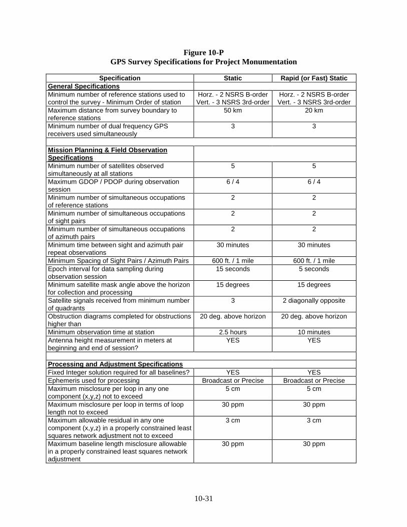
procedures will conform to the standards as defined in this section, for routine VDOT surveys, shown hereon as 2a through 2o. The intent of these procedures is to produce GPS surveys and data for the Project Control Monumentation that meets a geometric accuracy of 1:100,000 at the 68% confidence interval. A list of specifications is included as Figure 10-P, for easy reference.
2a. A minimum of three (3) GPS receivers shall be used simultaneously during all Static & Rapid Static GPS sessions. 2b. Existing or known points that will be used to control the survey shall be occupied simultaneously during the initial observation sessions. This is a check to ensure that existing, known or network control has not been disturbed and that the published values are, indeed correct. This is an integral part of the mission plan.
2c. Horizontal networks shall be connected to a minimum of two (2) NGS B-order (or higher) stations (see #1 of this section). At least one benchmark shall be used and held fixed for surveys where horizontal values will be paramount. The use of eccentric horizontal stations is not permitted. 2d. Vertical networks shall be connected to a minimum of three (3) third-order (or higher) bench marks. At least two of the benchmarks shall be near the project boundary to help determine the geoid separation of the project area.
2e. Sight (or station) pairs that are to be established by GPS methods to provide azimuths for the survey shall be inter-visible and spaced no less than 600 feet apart. Azimuth pairs that are to be established by GPS methods shall be spaced approximately one mile apart at a minimum and no more than 3 miles apart. Each sight (or station) pair and each azimuth pair shall be occupied at least twice simultaneously and separated by a minimum of one-half hour to create a redundant, direct connection between project control points. A sample network scheme is included as Figure 10-B.

10-4
2f. For each session, a minimum of 5 satellites shall be observed simultaneously. The Geometry Dilution of Precision (GDOP), shall never be greater than 6 at any time during the observation session. The Position Dilution Precision (PDOP) shall never be greater than 4 at any time during the observation session. Acceptable GDOP & PDOP values can be achieved through good mission planning practices and utilization of mission planning software.
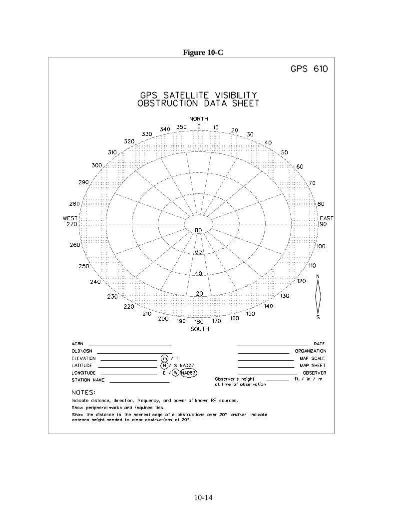
2g. For each session, data sampling shall have an epoch time interval of 5 seconds for Rapid Static survey procedures and 15 seconds for Static survey procedures. Satellite signals shall be observed from a minimum of 2 quadrants that are diagonally opposite from each other during Rapid Static survey missions. Satellite signals shall be observed from a minimum of 3 quadrants during a Static survey mission. This requirement shall be met while monitoring data collection in the field. It will also be verified by the GDOP value. 2h. Satellite receivers and processing software shall be programmed such that any satellite data below an elevation mask of 15 degrees shall not be used in the processing of baseline vectors. Any data below the 15-degree elevation mask would be questionable due to effects of atmospheric refraction. 2i. During reconnaissance and each observation session, careful notes or obstruction diagrams (see Figure 10-C) shall be recorded for any obstructions that are 20 degrees or higher above the horizon. Proper mission planning can minimize the effects of any obstructions and maximize the opportunity for a productive observation session. 2j. The geoid model used shall be the 2012A Geoid Model. This version shall be the model used for determining the geoid separation for each project control point and subsequent elevation.
2k. The ellipsoid model, used for determining elevation of the ellipsoid, shall be the WGS 1984 ellipsoid model. 2l. VDOT requires that the final adjusted coordinates for the GPS project shall be the product of a three-dimensional least squares adjustment software package.
2m. Static observation procedures shall be required for all baselines with a length of 20 kilometers (km) or longer. For a baseline length between 20 and 50 kilometers, observation sessions shall be at a minimum, 2.5 hours plus one minute per kilometer of baseline length for that session. For a baseline length between 50 and 100 kilometers, observation sessions shall be at a minimum, 3.5 hours plus one minute per kilometer of baseline length for that session. Proper mission planning and point site selections are vital to the success of the observing session.
2n. Rapid Static observation procedures shall be required for all baselines shorter than 20 kilometers (km) in length. Observation sessions shall be at a minimum, 10 minutes plus one minute per kilometer of baseline length for that session. Proper mission
10-5
planning and point site selections are vital to the success of the observing session. From a conservative standpoint, it is strongly recommended to add additional time to minimize the effect of solar activity, atmospheric refraction and unhealthy satellites. 2o. Determination of observation duration will be a function of the spacing of known control, distance of known control to survey project control, and the length of the project corridor. Again, if control is farther than 20 kilometers from the project, static observation procedures will control. 3. Securing Photogrammetry Control. Securing control for photogrammetry will also
follow the same guidelines as listed above. If control is nearby, the photogrammetry mission can be accomplished with rapid static observation procedures using “leap-frog” or traversing techniques through the control such that direct measurements are made between consecutive targets. Intermittent ties to the existing, known control and/or the monumented project control should be made during the mission. Proper mission planning techniques will develop the best results and checks for the mission. The adjustment of photogrammetry control should be independent of the VDOT Project Control Monumentation adjustment.
4. Utilizing RTK GPS on VDOT Projects. At the time of this revision to the Survey
manual, VDOT is currently investigating the potential advantages and disadvantages in the use of Real-Time Kinematic (RTK) GPS surveying equipment, capable of achieving a 2-cm positional accuracy. Therefore, VDOT has not developed any guidelines or specifications for RTK GPS surveying procedures. RTK GPS survey techniques for securing photo control and topography will be acceptable to VDOT. Prior to securing photo control, the surveyor shall have a base unit set on known control and shall check the values at another control point with the roving unit. The surveyor must provide proof of photo control points being measured at least twice by RTK methods, spot-checked by conventional survey methods, and that the positional differences are insignificant. The surveyor shall verify that the positional accuracy meets or exceeds the survey specifications. Any questions regarding field procedures may be directed to VDOT’s Geodetic Surveys Engineer.
Sec. 10.05 Quality Control Procedures
This section of the Survey Manual will assist the surveyor with the minimum field practices to ensure quality GPS survey data for VDOT. As with any high-tech measuring device, certain standards of care should be enforced in the use and maintenance of the equipment. The following are a few of the procedures that are followed by VDOT surveyors to help minimize positioning and field errors and ensure a good quality with the field collected data.
a. The tribrach, for each unit, should periodically be checked so that the antenna is being
centered accurately over the point. This can usually involve adjustment of the optical plummet and, in the worst case, the spirit level.

10-6
b. Care should be taken when setting a control monument or station, (see Figure 10-D) so that the effect of obstructions or canopy can be minimized. The monument and disk, or iron pin should be set according to normal VDOT procedures.
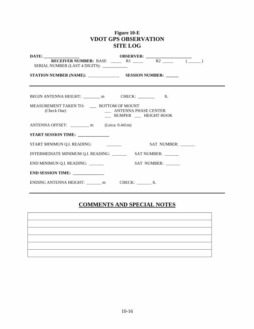
c. A site log form (see Figure 10-E) has been developed by VDOT for VDOT
surveyors to corroborate data entered into the receiver. One site-log form shall be filled out for each receiver for each occupation. The pertinent data includes: the date, observer, receiver #, station occupied (name), beginning antenna height, the antenna offset, session start time, start intermediate and end minimum QI & satellite number, end session time, end antenna height and comments. The form is self-explanatory. It is the responsibility of the surveyor operating the receiver to complete each form. The QI is the Quality Index of the satellite signal being received from each satellite. Regarding VDOT’s equipment, Leica System 300, a value of 99 is best. Regarding Leica’s System 500, a QI of 99 is best and anything below 92 is unacceptable. The norm for this system is either 99 or 92. VDOT requires knowledge of which value is lowest and from which satellite. This knowledge will assist with processing baselines later on. The comment section is for the surveyor operating the receiver to describe any problems affecting the satellite data or satellite signal received.
d. The antenna height will be measured in meters. Measurements for antenna height
shall be taken at the beginning and end of each session. If a station is to be occupied simultaneously through more than one session. The antenna will be reset over the station and a new antenna height at the beginning and end of each session will be measured. It is the responsibility of the surveyor to insure that the antenna height measured in the field is recorded correctly on the site log form and entered correctly into the receiver. Please refer to Figure 10-A, for assistance with the components of the antenna height measurements.
e. Prior to every new project, the memory card of the receiver should be formatted (or
cleared) once it has been definitely proven that the data has been downloaded and saved. It shall be the priority of the person who downloads the mission data to clear the cards of data only after a successful download and back up has been verified. Verification of a successful download will consist of examining mission data for session times, antenna height, and baseline quality and saving the data to another source or location.
f. Two-way radios shall not be used within 25 feet of the GPS receiver. Vehicles will
be parked a minimum of 50 feet away from the GPS receiver.
g. Every member of the GPS survey mission should know his or her responsibilities,
session starting and ending times, station locations and basic operation of the GPS equipment.

10-7
Sec. 10.06 Deliverables All GPS “subject data” for VDOT contracted surveys (either primary control or
photogrammetric control) shall be delivered to VDOT’s Geodetic Surveys Engineer for a quality control check and evaluation. This information will be delivered to the Geodetic Surveys Engineer before the entire VDOT survey is due.
The subject data that is to be delivered to the Geodetic Surveys Engineer shall include, at
a minimum, every item on the list depicted below. a. A sketch, on 8 ½” X 11” sheet of paper, containing the known network control points
(NGS, USGS, etc.) and the project control, with ID’s. b. A copy of data sheets published for each known network control point used in the
adjustment. This data sheet shall include station name, Geographic Coordinates, ellipsoidal heights, orthometric heights, published state plane coordinates, “how to reach” descriptions and point description. A copy of an NGS data sheet is acceptable for the known control points. The same format is acceptable for the project control points. Photogrammetric control points shall be identified on the project control sketch only. Descriptions or measured swing-ties for photo control shall not be included or delivered to VDOT’s Geodetic Surveys Engineer.
c. A constrained three-dimensional adjustment report showing the latitude and longitude
of all horizontal points, all benchmarks, and all ellipsoidal heights held fixed shall be delivered to VDOT’s Geodetic Surveys Engineer. The report should depict how the adjustment affects each point and the residuals of each baseline vector.
d. A listing of final adjusted geographic coordinates, ellipsoidal heights, and geoid
separations for each station, including stations held fixed. The final adjusted geographic coordinates shall be listed with their respective positional error.
e. A listing of final adjusted metric state plane coordinates with orthometric heights,
including stations held fixed. f. All copies of site log forms, either VDOT’s OR a similar form, as prepared by field
surveyors. g. All copies of any obstruction diagrams (Figure 10-C), if not included with site logs. h. A copy of the mission plan. This mission plan will include session times, occupation
duration and types of receivers used with manufacturer’s standard antenna phase-center offset included.
i. A one-page summary of the GPS mission. The report should include:
• reasons for fixing and floating stations,
10-8
• evaluation of adjustment results,
• Total man-hours spent by crew and processor and overall assessment of the
mission and performance of equipment. j. All completed LD-200 cards (latest version, see Figure 10-F). k. One copy of original GPS raw data (either on 3 ½” HD diskette or CD) in Leica,
Trimble, Topcon, or RINEX-2 format. Sec. 10.07 LD-200 Card (Rev. 8/00) As of 7/01/99, VDOT reverted to preparing surveys and design plans in imperial units, using the U.S. Survey Foot. This meant revisions to the survey manual. It also meant revising the LD-200 card. GPS has become a major tool for surveyors. The old LD-200 card did not have enough supporting data for a surveyor to use. Some new revisions include: adding Latitude and Longitude (out to 5 decimal places), the Geoid and ellipsoid heights, control station or VDOT project station that adjusted values are based on, horizontal closure and the sketch and detailed description (on back of printed version, below on electronic version). This new LD-200 Horizontal Control card (see Figure 10-F) will help the surveyor by giving more background knowledge of the coordinate origin and inspire more surveyors to turn in an electronic version of the card and data. The card is a cell in the Microstation cell library (see Appendix A).
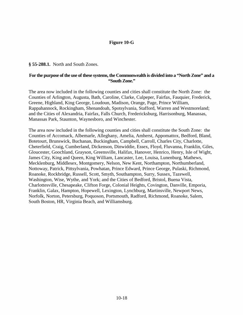
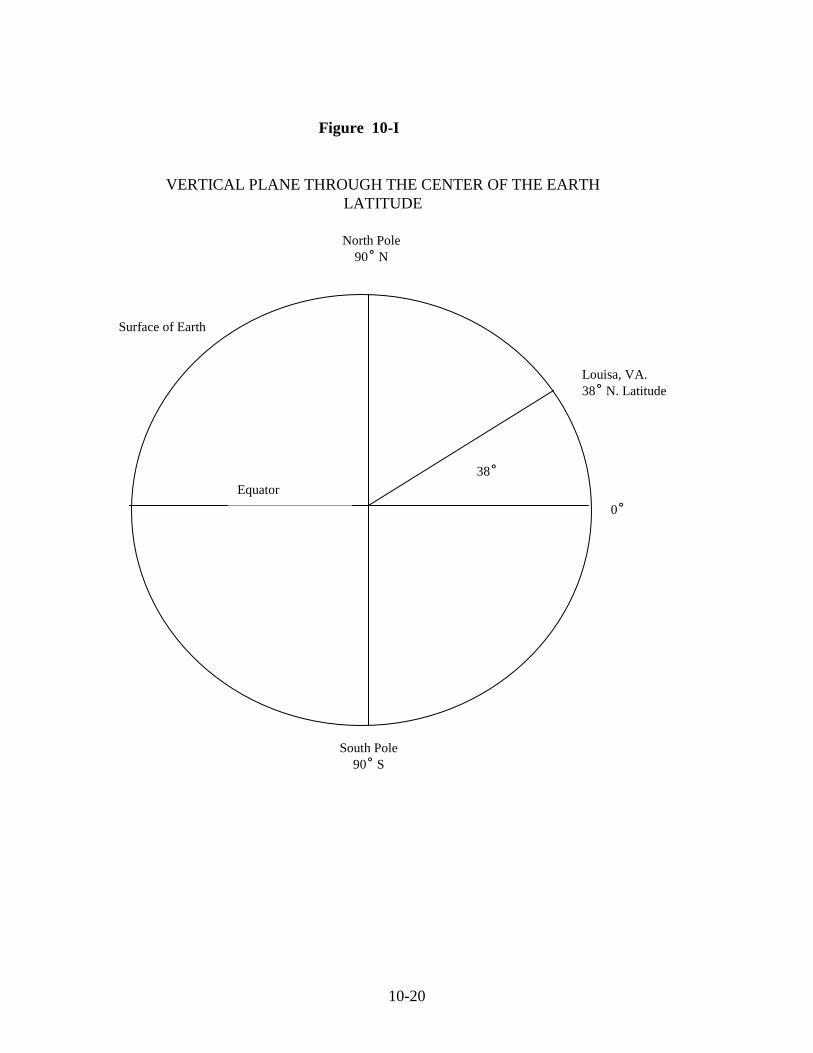
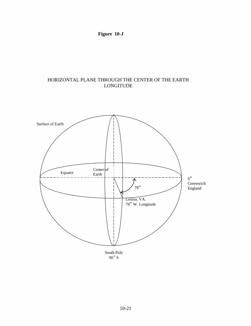
Sec. 10.08 Basis of the State Plane Coordinate System To make full use of the State Plane Coordinate System, one must understand how the plane coordinates of any given point are directly related to the geodetic coordinates (latitude and longitude) of that point. First, it should be understood that the latitude of a point is the angular difference between that point and the equator. The longitude of a point is the angular difference between that point and the zero meridian, which arbitrarily passes through Greenwich, England. Virginia is divided into two (2) Lambert Conformal Conic Projection zones, North and South. The dividing line runs along latitude of 38˚. The Code of Virginia §55-288.1 divides the zones along the county lines, as listed on Figure 10-G. A point is positioned using GPS methods and the position is referenced to a geodetic coordinate system, latitude and longitude. The Geodetic Coordinates are directly related to the Virginia State Plane Coordinate System by definition in The Code of Virginia §55-292 (see Figure 10-H). For example, if we need to define a point in Louisa, Virginia, the latitude can be defined as the angular difference between that point and the equator as shown in Figure 10-I. Similarly, the longitude can be defined as the angular difference from Greenwich, England, as shown in Figure 10-J. This point would be defined as 38O North latitude and 78O West longitude. This would relate our point in Louisa, Virginia to any other point on the surface of the earth. This is a very precise and universally accepted method of defining positions on the surface of the earth. However, while the system of geodetic coordinates is precise, the computations associated with them are

10-9
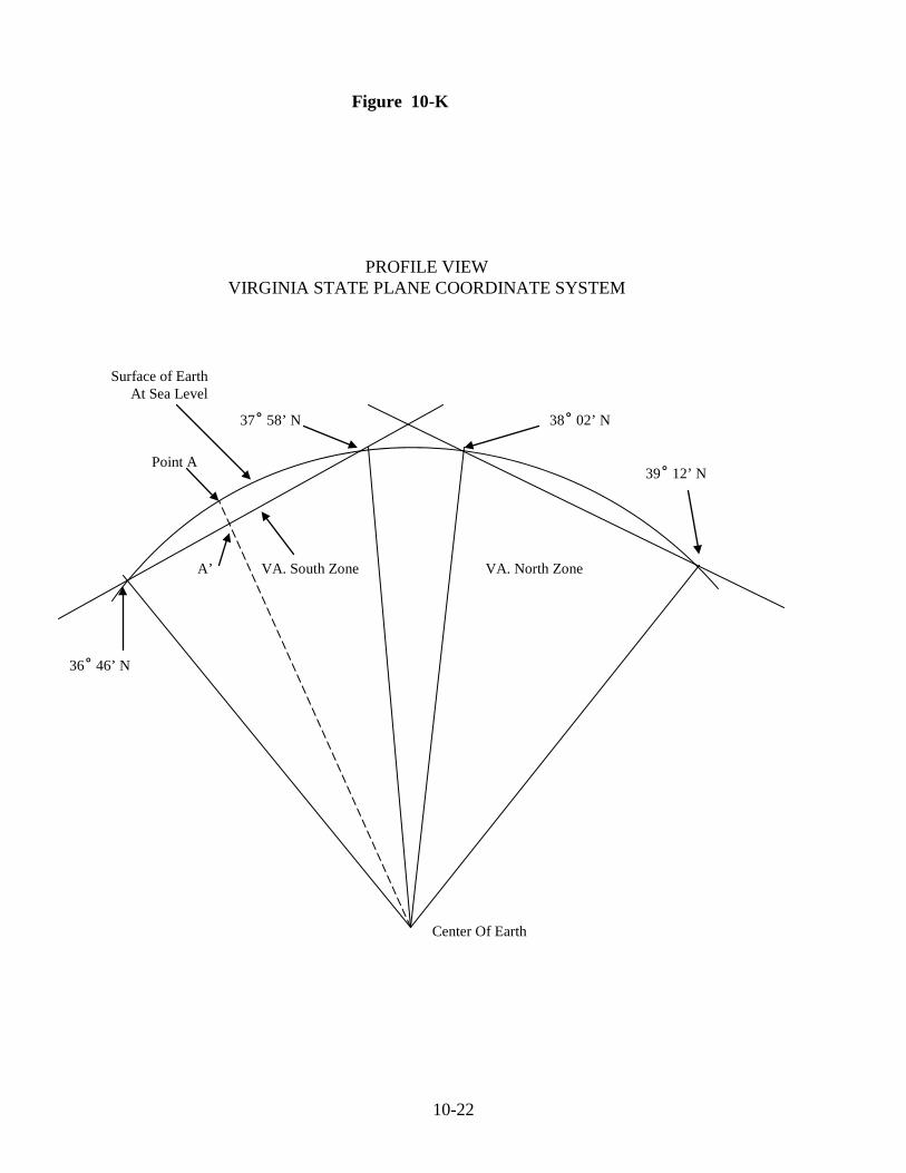
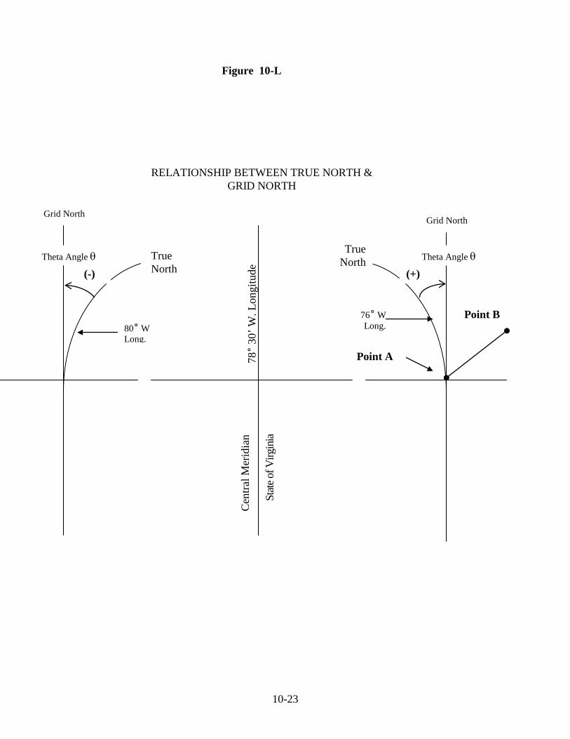
unnecessarily complex when one is dealing with a relatively small area on the face of the earth, and it becomes expedient to establish a simpler model of the earth while still maintaining acceptable accuracy. This can be accomplished by utilizing the VDOT State Plane Coordinate System, which is based on NAD83 coordinate values. This plane coordinate system allows the use of relatively simple theories and formulae of plane geometry and trigonometry used by surveyors since the beginning of history for the measurement of land and structures on the earth's surface. The interstate highway system that we enjoy today is one of the prime contributing factors to the establishment of the Virginia State Plane Coordinate System and similar systems employed by all the other states in the United States. State and Federal engineers agreed that plane coordinate systems would be established to allow accurate surveys to be performed, which with the proper corrections applied, would be accurate, nationwide. In addition, the various zones in these systems would be small enough so that if no corrections were applied, positional accuracy within the respective zones would exceed 1 part in 10,000. Sec. 10.09 Depiction of Two Coordinate Zones Figure 10-K is a graphic representation of the State of Virginia showing the two coordinate systems. Refer to the Virginia South Zone and note that the line intersects the surface of the earth at two points similar to the way the long chord of a curve intersects the P. C. and P. T. of that curve. Likewise, the distance along the line from 36O 46' to Point A would be shorter than the distance along the arc from 36O 46' to Point A. The relationship between these two distances would give us a scale factor to apply to distances measured along the arc to reduce them to distances along the line. At 36O 46' and 37O 58' these corrections would be expressed as 1.0000000 multiplied by the distance measured. As you move to the center of the zone; this factor decreased to 0.9999454. As you proceed South from 36O 46' to the North Carolina line, the correction increased to about 1.0000464. You will note that this variation from high to low gives a possible difference in 1000 feet of 0.10 feet, which was the required accuracy for the coordinate system. This basic idea holds true for the Virginia North Zone. Sec. 10.10 Relation of Grid North and True North All lines or meridians of longitude run through the North and South Pole. Therefore, they cannot be parallel. The central meridian for the State of Virginia is 78° 30' West longitude for both the North and South Zones. This means that throughout both zones grid north is exactly parallel to the 78° 30' West longitude, central meridian. The angular difference between the true north and grid north is called the θ (theta) angle. Figure 10-L) shows this graphically.

10-10
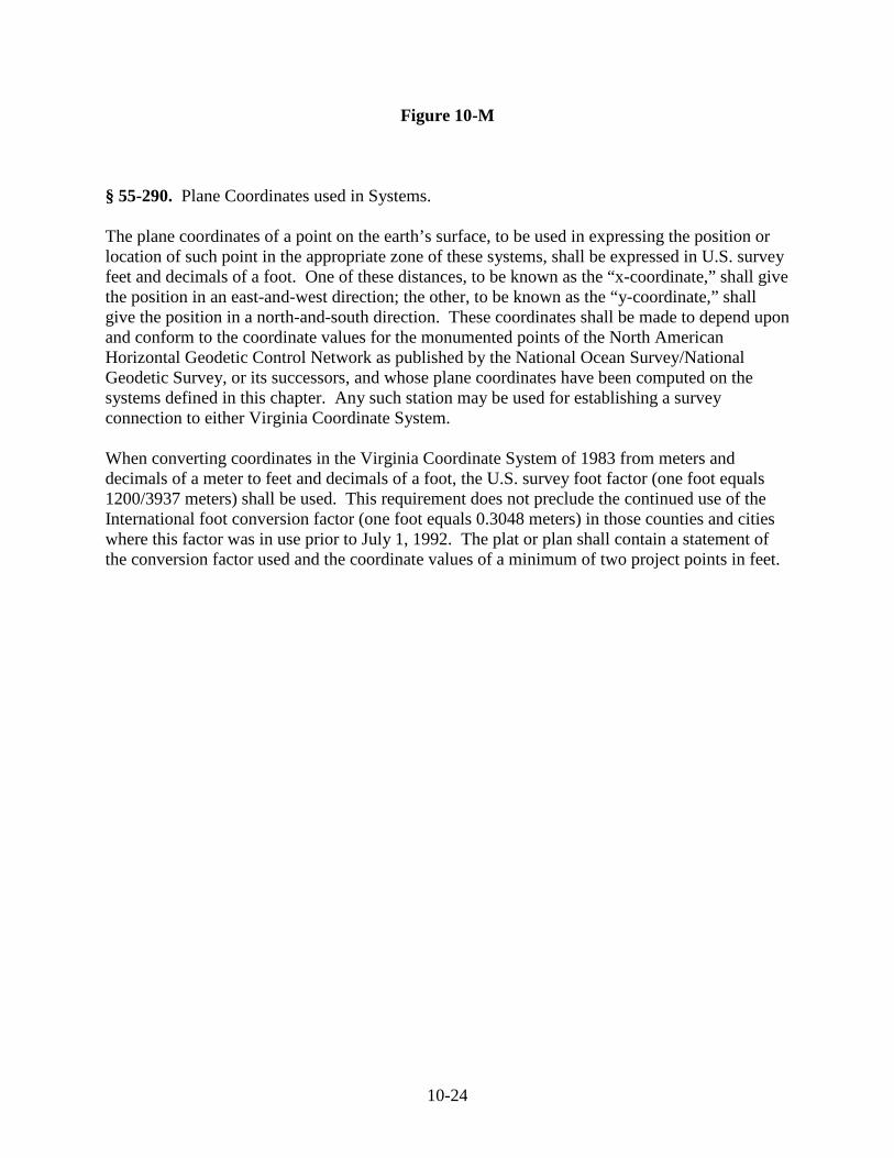
Sec. 10.11 The VDOT Project Coordinate System Beginning June 1, 2014 all new VDOT Projects will be based on the new VDOT Project Coordinate System outlined below (Now known as “VDOT Project Coordinates-2014”). To convert Virginia State Plane Coordinates (based on the US Survey Foot) to VDOT Project Coordinates-2014, the coordinates will need to be multiplied by the combined Scale & Elevation Factor for each specific project. One method of obtaining the scale factor for each project will be to submit GPS data to OPUS (NGS utility) for each primary control point on the project. Submitting “Static” data to OPUS (minimum 2- hour occupations per point) will be required. Once the OPUS results are obtained, take the average of the combined factors under the State Plane Coordinates for the primary control points. Once this step is done, the inverse function (1/x) should be applied, resulting in the Combined Scale Factor for the project (9 decimal places- Example= 1.000000009). This is only one method of obtaining the scale factor for a project. Regardless of the method used, the procedure shall be described in detail in the project notes as well in the Project Deliverables (Sec. 10.06).◊ Special Note on Projects that predate June 1, 2014:◊ Projects completed or started prior to January 1, 2014 should continue to use the former language below. The VDOT Coordinate System is based on NAD83 METRIC values as defined in The Code of Virginia §55-292 (see Figure 10-H). To convert NAD83 METRIC to VDOT Project coordinates (Imperial Units), first depending on the zone you are working in, subtract 1,000,000 meters from the South Zone Northing value (or 2,000,000 meters from the North Zone Northing value). Next, subtract 2,500,000 meters from the Easting value. Next, multiply the Northing and Easting values by 3.28083333333 (the conversion for the U. S. Survey Foot as defined in The Code of Virginia §55-290, see Figure 10-M). Last, multiply the Northing and Easting values by the Combined County Scale & Elevation Factor. Figure 10-N is a list of the combined scale and elevation factor for the counties. This produces VDOT Project Coordinates (in Imperial Units) for a given project. A reverse of this procedure will transform VDOT Project Coordinates back the original NAD83 METRIC values. See Figure 10-F, showing the use of the above procedures as depicted on a LD-200 Horizontal Control Station Reference Card.
◊ April 2014 ◊ April 2014
10-11
Sec. 10.12 Airborne GPS
1. Airborne GPS techniques can be used to acquire supplemental control for use on photogrammetric projects.
2. It is important to maintain Reference Base Stations over known control points during the duration of the flight.
3. These Reference Stations should be spaced 10 to 25 kilometers from the project. The entire project should be reachable within this range.
4. The range of 10 to 25 kilometers should be scrutinized keeping in mind the accuracy needs of the project. A general rule of thumb, under optimal conditions, would be about 1 cm of residual per 10 kilometers of baseline distance. Bear in mind, there usually are other factors involved that could result in an increase in your residual values. i.e. a poor GDOP value
5. If multiple Reference Stations are required, then no part of the project should be farther than 10 to 25 kilometers from at least one of the Reference Stations.
6. Reference Stations as well as Rovers should be set to collect one second epoch data.

10-12
Figure 10-A

10-13
Figure 10-B HARN Pt. #1 s Δ D Δ A =BM Sight Pair 600 ft. min. Δ C Approx 1 mile Between Azimuth Pairs B Δ s HARN Pt. #2 A,B,C,D = VDOT Route Survey Control Points; Coordinates to be Determined HARN #1 to HARN #2 = 17 km = BM on NAVD88 datum; GDOP = 2.5; 6 Satellites HARN Points Have Known X, Y & Z Values Observation Session #1, 4 Receivers, Duration 30 Minutes Minimum, Use Rapid Static Procedures, Occupy HARN #1, HARN#2, BM & A. Observation Session #2, 4 Receivers, A-C = 3 km, Duration 15 Minutes Minimum, Use Rapid Static Procedures, Occupy BM, A, B & C. Observation Session #3, 4 Receivers, B-D = 3 km, Duration 15 Minutes Minimum, Use Rapid Static Procedures, Occupy B, C, D & BM. Observation Session #4, 4 Receivers, Duration 30 Minutes Minimum, Use Rapid Static Procedures, Occupy HARN #1, HARN#2, BM & D. Observation Session #5, 4 Receivers, Duration 15 Minutes Minimum, Use Rapid Static Procedures, Occupy A, B, C & D. Figure 10-B is an example of one observing session scheme. This illustrates one way to design a mission, but a mission is not limited to one scheme to accomplish the same results. An observing scheme should be developed to meet your specific accuracy standard criteria. The best source of information to develop observing session scheme or mission plan is “Geometric Geodetic Accuracy Standard and Specifications for Using GPS Relative Positioning Techniques”. FGCC ver. 5.0 8/19/89.
10-14
Figure 10-C

10-15
Stamped VDOT Disk Set In Concrete Flush With the Ground Line
Figure 10-D
Minimum 36” Deep
Mixed Sacrete With Steel Rebar
Ground Line
10-16
Figure 10-E VDOT GPS OBSERVATION
SITE LOG
DATE: _________________ OBSERVER: ______________________ RECEIVER NUMBER: BASE _____ R1 _____ R2 _____ ( ______ )
SERIAL NUMBER (LAST 4 DIGITS): ____________ STATION NUMBER (NAME): _______________ SESSION NUMBER: ______
BEGIN ANTENNA HEIGHT: ________ m CHECK: ________ ft. MEASUREMENT TAKEN TO: ___ BOTTOM OF MOUNT (Check One) ___ ANTENNA PHASE CENTER ___ BUMPER ___ HEIGHT HOOK ANTENNA OFFSET: _________ m (Leica: 0.441m) START SESSION TIME: _______________ START MINIMUN Q.I. READING: _______ SAT NUMBER: _______ INTERMEDIATE MINIMUM Q.I. READING: _______ SAT NUMBER: _______ END MINIMUN Q.I. READING: _______ SAT NUMBER: _______ END SESSION TIME: _______________ ENDING ANTENNA HEIGHT: _______ m CHECK: _______ ft.
COMMENTS AND SPECIAL NOTES

10-17
Figure 10-F
Sample Horizontal Control Card “LD-200”
10-18
Figure 10-G § 55-288.1. North and South Zones. For the purpose of the use of these systems, the Commonwealth is divided into a “North Zone” and a
“South Zone.” The area now included in the following counties and cities shall constitute the North Zone: the Counties of Arlington, Augusta, Bath, Caroline, Clarke, Culpeper, Fairfax, Fauquier, Frederick, Greene, Highland, King George, Loudoun, Madison, Orange, Page, Prince William, Rappahannock, Rockingham, Shenandoah, Spotsylvania, Stafford, Warren and Westmoreland; and the Cities of Alexandria, Fairfax, Falls Church, Fredericksburg, Harrisonburg, Manassas, Manassas Park, Staunton, Waynesboro, and Winchester. The area now included in the following counties and cities shall constitute the South Zone: the Counties of Accomack, Albemarle, Alleghany, Amelia, Amherst, Appomattox, Bedford, Bland, Botetourt, Brunswick, Buchanan, Buckingham, Campbell, Carroll, Charles City, Charlotte, Cheterfield, Craig, Cumberland, Dickenson, Dinwiddie, Essex, Floyd, Fluvanna, Franklin, Giles, Gloucester, Goochland, Grayson, Greensville, Halifax, Hanover, Henrico, Henry, Isle of Wight, James City, King and Queen, King William, Lancaster, Lee, Louisa, Lunenburg, Mathews, Mecklenburg, Middlesex, Montgomery, Nelson, New Kent, Northampton, Northumberland, Nottoway, Patrick, Pittsylvania, Powhatan, Prince Edward, Prince George, Pulaski, Richmond, Roanoke, Rockbridge, Russell, Scott, Smyth, Southampton, Surry, Sussex, Tazewell, Washington, Wise, Wythe, and York; and the Cities of Bedford, Bristol, Buena Vista, Charlottesville, Chesapeake, Clifton Forge, Colonial Heights, Covington, Danville, Emporia, Franklin, Galax, Hampton, Hopewell, Lexington, Lynchburg, Martinsville, Newport News, Norfolk, Norton, Petersburg, Poquoson, Portsmouth, Radford, Richmond, Roanoke, Salem, South Boston, HR, Virginia Beach, and Williamsburg.

10-19
Figure 10-H
§ 55-292. Definition of Systems by National Ocean Survey/National Geodetic Survey; adopted. For purposes of more precisely defining the Virginia Coordinate System of 1927, the following definition by the National Ocean Survey/National Geodetic Survey is adopted: The Virginia Coordinate System of 1927, North Zone, is a Lambert conformal projection of the Clarke spheroid of 1896, having standard parallels at north latitudes 38º02’ and 39º12’, along which parallels the scale shall be exact. The origin of coordinates is at the intersection of the meridian 78º30’ west of Greenwich with the parallel 37º40’ north latitude, such origin being given the coordinates: x = 2,000,000’, and y = 0’. The Virginia Coordinate System of 1927, South Zone, is a Lambert conformal projection of the Clarke spheroid of 1896, having standard parallels at north latitudes 36º46’ and 37º58’, along which parallels the scale shall be exact. The origin of coordinates is at the intersection of the meridian 78º30’ west of Greenwich with the parallel 36º20’ north latitude, such origin being given the coordinates: x = 2,000,000’and y = 0’. For purposes of more precisely defining the Virginia Coordinate System of 1983, the following definition by the National Ocean Survey/National Geodetic Survey is adopted: The Virginia Coordinate System of 1983, North Zone, is a Lambert conformal conic projection based on the North American Datum of 1983, having standard parallels at north latitudes 38º02’ and 39º12’, along which parallels the scale shall be exact. The origin of coordinates is at the intersection of the meridian 78º30’ west of Greenwich and the parallel 37º40’ north latitude. The origin being given the coordinates: x = 3,500,000 meters and y = 2,000,000 meters. The Virginia Coordinate System of 1983, South Zone, is a Lambert conformal conic projection based on the North American Datum of 1983, having standard parallels at north latitudes 36º46’ and 37º58’, along which parallels the scale shall be exact. The origin of coordinates is at the intersection of the meridian 78º30’ west of Greenwich and the parallel 36º20’ north latitude. This origin is given the coordinates: x = 3,500,000 meters and y = 1,000,000 meters.
10-20
Louisa, VA. 38˚ N. Latitude
38˚
North Pole 90˚ N
South Pole 90˚ S
0˚ Equator
Surface of Earth
VERTICAL PLANE THROUGH THE CENTER OF THE EARTH LATITUDE
Figure 10-I
10-21
South Pole 90˚ S
0˚ Greenwich England
Equator
Surface of Earth
HORIZONTAL PLANE THROUGH THE CENTER OF THE EARTH LONGITUDE
Figure 10-J
Louisa, VA. 78˚ W. Longitude
78˚
Center of Earth
10-22
PROFILE VIEW VIRGINIA STATE PLANE COORDINATE SYSTEM
Figure 10-K
VA. North Zone VA. South Zone
Center Of Earth
39˚ 12’ N
38˚ 02’ N 37˚ 58’ N
A’
Point A
36˚ 46’ N
Surface of Earth At Sea Level
10-23
RELATIONSHIP BETWEEN TRUE NORTH & GRID NORTH
Figure 10-L
True North
True North
78˚
30’ W
. Lon
gitu
de
Cen
tral M
erid
ian
St
ate o
f Virg
inia
Point B 80˚ W Long.
76˚ W Long.
Theta Angle θ Theta Angle θ
Grid North Grid North
Point A
(+) (-)
10-24
Figure 10-M § 55-290. Plane Coordinates used in Systems. The plane coordinates of a point on the earth’s surface, to be used in expressing the position or location of such point in the appropriate zone of these systems, shall be expressed in U.S. survey feet and decimals of a foot. One of these distances, to be known as the “x-coordinate,” shall give the position in an east-and-west direction; the other, to be known as the “y-coordinate,” shall give the position in a north-and-south direction. These coordinates shall be made to depend upon and conform to the coordinate values for the monumented points of the North American Horizontal Geodetic Control Network as published by the National Ocean Survey/National Geodetic Survey, or its successors, and whose plane coordinates have been computed on the systems defined in this chapter. Any such station may be used for establishing a survey connection to either Virginia Coordinate System. When converting coordinates in the Virginia Coordinate System of 1983 from meters and decimals of a meter to feet and decimals of a foot, the U.S. survey foot factor (one foot equals 1200/3937 meters) shall be used. This requirement does not preclude the continued use of the International foot conversion factor (one foot equals 0.3048 meters) in those counties and cities where this factor was in use prior to July 1, 1992. The plat or plan shall contain a statement of the conversion factor used and the coordinate values of a minimum of two project points in feet.

10-25
Figure 10-N COMBINED SCALE AND ELEVATION FACTOR FOR THE COUNTY
000 1.00006 Arlington 054 1.00002 Louisa
001 1.00004 Accomack 055 1.00005 Lunenburg 002 1.00002 Albemarle 056 1.00007 Madison 003 1.00015 Alleghany 057 1.00005 Mathews 004 1.00007 Amelia 058 1.00000 Mecklenburg 005 1.00009 Amherst 059 1.00005 Middlesex 006 1.00008 Appomattox 060 1.00015 Montgomery 007 1.00009 Augusta 061 1.00000 City of HR 008 1.00012 Bath 062 1.00007 Nelson 009 1.00009 Bedford 063 1.00005 New Kent 010 1.00017 Bland 064 1.00000 Nor. Ches. Ports. 011 1.00011 Botetourt 065 1.00004 Northampton 012 1.00001 Brunswick 066 1.00002 Northumberland 013 1.00015 Buchanan 067 1.00007 Nottoway 014 1.00007 Buckingham 068 1.00006 Orange 015 1.00007 Campbell 069 1.00010 Page 016 1.00001 Caroline 070 1.00004 Patrick 017 1.00011 Carroll 071 1.00002 Pittsylvania 018 1.00006 Charles City 072 1.00006 Powhatan 019 1.00006 Charlotte 073 1.00007 Prince Edward 020 1.00006 Chesterfield 074 1.00006 Prince George 021 1.00004 Clarke 075 1.00000 City of VA Beach 022 1.00017 Craig 076 1.00006 Prince William 023 1.00007 Culpeper 077 1.00014 Pulaski 024 1.00007 Cumberland 078 1.00009 Rappahannock 025 1.00014 Dickenson 079 1.00001 Richmond 026 1.00005 Dinwiddie 080 1.00013 Roanoke 027 1.00004 City of Hampton 081 1.00008 Rockbridge 028 1.00001 Essex 082 1.00011 Rockingham 029 1.00006 Fairfax 083 1.00012 Russell 030 1.00008 Fauquier 084 1.00011 Scott 031 1.00012 Floyd 085 1.00009 Shenandoah 032 1.00004 Fluvanna 086 1.00015 Smyth 033 1.00009 Franklin 087 1.00000 Southampton 034 1.00004 Frederick 088 1.00004 Spotsylvania 035 1.00017 Giles 089 1.00006 Stafford 036 1.00005 Gloucester 090 1.00005 Surry 037 1.00005 Goochland 091 1.00003 Sussex 038 1.00011 Grayson 092 1.00019 Tazewell 039 1.00007 Greene 093 1.00007 Warren 040 1.00000 Greensville 094 1.00004 City of Newport News 041 1.00002 Halifax 095 1.00009 Washington 042 1.00004 Hanover 096 1.00002 Westmoreland 043 1.00006 Henrico 097 1.00015 Wise 044 1.00003 Henry 098 1.00014 Wythe 045 1.00016 Highland 099 1.00005 York 046 1.00002 Isle of Wight 047 1.00005 James City 048 1.00004 King George 049 1.00004 King & Queen 050 1.00004 King William 051 1.00003 Lancaster 052 1.00006 Lee 053 1.00005 Loudoun

10-26
Figure 10-O
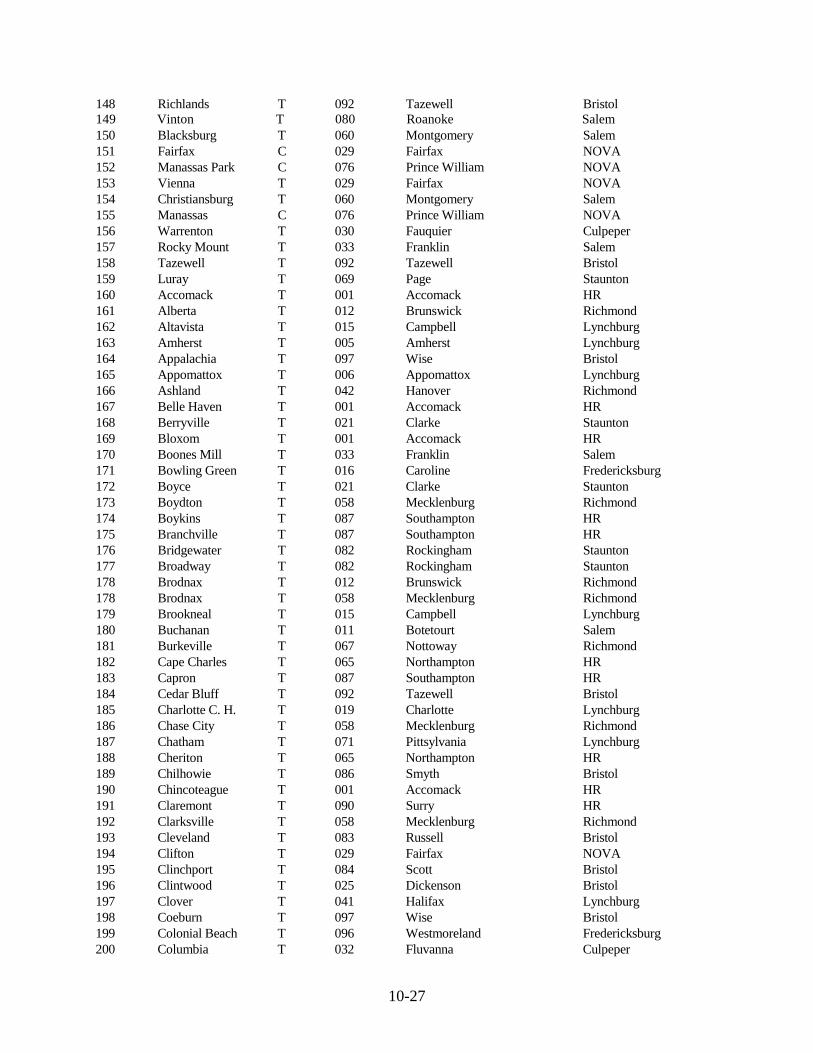
COUNTY CODE NUMBER REFERENCE FOR CITIES AND TOWNS City or Town Code County Location District 100 Alexandria C 000 Arlington Nova 101 Big Stone Gap T 097 Wise Bristol 102 Bristol C 095 Washington Bristol 103 Buena Vista C 081 Rockbridge Staunton 104 Charlottesville C 002 Albemarle Culpeper 105 Clifton Forge C 003 Alleghany Staunton 106 Colonial Heights C 020 Chesterfield Richmond 107 Covington C 003 Alleghany Staunton 108 Danville C 071 Pittsylvania Lynchburg 109 Emporia C 040 Greensville HR 110 Falls Church C 029 Fairfax NOVA 111 Fredericksburg C 088 Spotsylvania Fredericksburg 112 Front Royal T 093 Warren Staunton 113 Galax C 017 Carroll Salem 114 Hampton C 027 City of Hampton HR 115 Harrisonburg C 082 Rockingham Staunton 116 Hopewell C 074 Prince George Richmond 117 Lexington C 081 Rockbridge Staunton 118 Lynchburg C 015 Campbell Lynchburg 119 Marion T 086 Smyth Bristol 120 Martinsville C 044 Henry Salem 121 Newport News C 094 City of Newport News HR 122 Norfolk C 064 City of Norfolk HR 123 Petersburg C 026 Dinwiddie Richmond 124 Portsmouth C 064 City of Portsmouth HR 125 Pulaski T 077 Pulaski Salem 126 Radford C 060 Montgomery Salem 127 Richmond C 020 Chesterfield Richmond 128 Roanoke C 080 Roanoke Salem 129 Salem C 080 Roanoke Salem 130 South Boston C (T) 041 Halifax Lynchburg 131 Chesapeake C 064 City of Chesapeake HR 132 Staunton C 007 Augusta Staunton 133 HR C 061 Nansemond HR 134 Virginia Beach C 075 City of Virginia Beach HR 135 136 Waynesboro C 007 Augusta Staunton 137 Williamsburg C 047 James City HR 138 Winchester C 034 Frederick Staunton 139 Wytheville T 098 Wythe Bristol 140 Abingdon T 095 Washington Bristol 141 Bedford C 009 Bedford Salem 142 Blackstone T 067 Nottoway Richmond 143 Bluefield T 092 Tazewell Bristol 144 Farmville T 073 Prince Edward Lynchburg 145 Franklin C 087 Southampton HR 146 Norton C 097 Wise Bristol 147 Poquoson C 099 York HR
10-27
148 Richlands T 092 Tazewell Bristol 149 Vinton T 080 Roanoke Salem 150 Blacksburg T 060 Montgomery Salem 151 Fairfax C 029 Fairfax NOVA 152 Manassas Park C 076 Prince William NOVA 153 Vienna T 029 Fairfax NOVA 154 Christiansburg T 060 Montgomery Salem 155 Manassas C 076 Prince William NOVA 156 Warrenton T 030 Fauquier Culpeper 157 Rocky Mount T 033 Franklin Salem 158 Tazewell T 092 Tazewell Bristol 159 Luray T 069 Page Staunton 160 Accomack T 001 Accomack HR 161 Alberta T 012 Brunswick Richmond 162 Altavista T 015 Campbell Lynchburg 163 Amherst T 005 Amherst Lynchburg 164 Appalachia T 097 Wise Bristol 165 Appomattox T 006 Appomattox Lynchburg 166 Ashland T 042 Hanover Richmond 167 Belle Haven T 001 Accomack HR 168 Berryville T 021 Clarke Staunton 169 Bloxom T 001 Accomack HR 170 Boones Mill T 033 Franklin Salem 171 Bowling Green T 016 Caroline Fredericksburg 172 Boyce T 021 Clarke Staunton 173 Boydton T 058 Mecklenburg Richmond 174 Boykins T 087 Southampton HR 175 Branchville T 087 Southampton HR 176 Bridgewater T 082 Rockingham Staunton 177 Broadway T 082 Rockingham Staunton 178 Brodnax T 012 Brunswick Richmond 178 Brodnax T 058 Mecklenburg Richmond 179 Brookneal T 015 Campbell Lynchburg 180 Buchanan T 011 Botetourt Salem 181 Burkeville T 067 Nottoway Richmond 182 Cape Charles T 065 Northampton HR 183 Capron T 087 Southampton HR 184 Cedar Bluff T 092 Tazewell Bristol 185 Charlotte C. H. T 019 Charlotte Lynchburg 186 Chase City T 058 Mecklenburg Richmond 187 Chatham T 071 Pittsylvania Lynchburg 188 Cheriton T 065 Northampton HR 189 Chilhowie T 086 Smyth Bristol 190 Chincoteague T 001 Accomack HR 191 Claremont T 090 Surry HR 192 Clarksville T 058 Mecklenburg Richmond 193 Cleveland T 083 Russell Bristol 194 Clifton T 029 Fairfax NOVA 195 Clinchport T 084 Scott Bristol 196 Clintwood T 025 Dickenson Bristol 197 Clover T 041 Halifax Lynchburg 198 Coeburn T 097 Wise Bristol 199 Colonial Beach T 096 Westmoreland Fredericksburg 200 Columbia T 032 Fluvanna Culpeper

10-28
201 Courtland T 087 Southampton HR 202 Craigsville T 007 Augusta Staunton 203 Crewe T 067 Nottoway Richmond 204 Culpeper T 023 Culpeper Culpeper 205 Damascus T 095 Washington Bristol 206 Dayton T 082 Rockingham Staunton 207 Dendron T 090 Surry HR 208 Dillwyn T 014 Buckingham Lynchburg 209 Drakes Branch T 019 Charlotte Lynchburg 210 Dublin T 077 Pulaski Salem 211 Duffield T 084 Scott Bristol 212 Dumfries T 076 Prince William NOVA 213 Dungannon T 084 Scott Bristol 214 Eastville T 065 Northampton HR 215 Edinburg T 085 Shenandoah Staunton 216 Elkton T 082 Rockingham Staunton 217 Exmore T 065 Northampton HR 218 Fincastle T 011 Botetourt Salem 219 Floyd T 031 Floyd Salem 220 Fries T 038 Grayson Bristol 221 Gate City T 084 Scott Bristol 222 Glade Spring T 095 Washington Bristol 223 Glasgow T 081 Rockbridge Staunton 224 Glen Lyn T 035 Giles Salem 225 Gordonsville T 068 Orange Culpeper 226 Goshen T 081 Rockbridge Staunton 227 Gretna T 071 Pittsylvania Lynchburg 228 Grottoes T 082 Rockingham Staunton 228 Grottoes T 007 Augusta Staunton 229 Grundy T 013 Buchanan Bristol 230 Halifax T 041 Halifax Lynchburg 231 Hallwood T 001 Accomack HR 232 Hamilton T 053 Loudoun NOVA 233 Haymarket T 076 Prince William NOVA 234 Haysi T 025 Dickenson Bristol 235 Herndon T 029 Fairfax NOVA 236 Hillsboro T 053 Loudoun NOVA 237 Hillsville T 017 Carroll Salem 238 Holland T 061 Nansemond HR 239 Honaker T 083 Russell Bristol 240 Independence T 038 Grayson Bristol 241 Iron Gate T 003 Alleghany Staunton 242 Irvington T 051 Lancaster Fredericksburg 243 Ivor T 087 Southampton HR 244 Jarratt T 091 Sussex HR 244 Jarratt T 040 Greensville HR 245 Jonesville T 052 Lee Bristol 246 Keller T 001 Accomack HR 247 Kenbridge T 055 Lunenburg Richmond 248 Keysville T 019 Charlotte Lynchburg 249 Kilmarnock T 051 Lancaster Fredericksburg 249 Kilmarnock T 066 Northumberland Fredericksburg 250 LaCrosse T 058 Mecklenburg Richmond 251 Lawrenceville T 012 Brunswick Richmond

10-29
252 Lebanon T 083 Russell Bristol 253 Leesburg T 053 Loudoun NOVA 254 Louisa T 054 Louisa Culpeper 255 Lovettsville T 053 Loudoun NOVA 256 Madison T 056 Madison Culpeper 257 McKenney T 026 Dinwiddie Richmond 258 Melfa T 001 Accomack HR 259 Middleburg T 053 Loudoun NOVA 260 Middletown T 034 Frederick Staunton 261 Mineral T 054 Louisa Culpeper 262 Monterey T 045 Highland Staunton 263 Montross T 096 Westmoreland Fredericksburg 264 Mt. Crawford T 082 Rockingham Staunton 265 Mt. Jackson T 085 Shenandoah Staunton 266 Narrows T 035 Giles Salem 267 Nassawadow T 065 Northampton HR 268 New Castle T 022 Craig Salem 269 New Market T 085 Shenandoah Staunton 270 Newsoms T 087 Southampton HR 271 Nicklesville T 084 Scott Bristol 272 Occoquan T 076 Prince William NOVA 273 Onancock T 001 Accomack HR 274 Onley T 001 Accomack HR 275 Orange T 068 Orange Culpeper 276 Painter T 001 Accomack HR 277 Pamplin City T 006 Appomattox Lynchburg 277 Pamplin City T 073 Prince Edward Lynchburg 278 Parksley T 001 Accomack HR 279 Pearisburg T 035 Giles Salem 280 Pembroke T 035 Giles Salem 281 Pennington Gap T 052 Lee Bristol 282 Phenix T 019 Charlotte Lynchburg 283 Pocahontas T 092 Tazewell Bristol 284 Port Royal T 016 Caroline Fredericksburg 285 Pound T 097 Wise Bristol 286 Purcellville T 053 Loudoun NOVA 287 Quantico T 076 Prince William NOVA 288 Remington T 030 Fauquier Culpeper 289 Rich Creek T 035 Giles Salem 290 Ridgeway T 044 Henry Salem 291 Round Hill T 053 Loudoun NOVA 292 Rural Retreat T 098 Wythe Bristol 293 Saint Charles T 052 Lee Bristol 294 Saint Paul T 097 Wise Bristol 295 Saltville T 086 Smyth Bristol 296 Saxis T 001 Accomack HR 297 Scottsburg T 041 Halifax Lynchburg 298 Scottsville T 002 Albemarle Culpeper 298 Scottsville T 032 Fluvanna Culpeper 299 Shenandoah T 069 Page Staunton 300 Smithfield T 046 Isle of Wight HR 301 South Hill T 058 Mecklenburg Richmond 302 Stanardsville T 039 Greene Culpeper 303 Stanley T 069 Page Staunton

10-30
304 Stephens City T 034 Frederick Staunton 305 Stony Creek T 091 Sussex HR 306 Strasburg T 085 Shenandoah Staunton 307 Stuart T 070 Patrick Salem 308 Surry T 090 Surry HR 309 Tangier T 001 Accomack HR 310 Tappahannock T 028 Essex Fredericksburg 311 The Plains T 030 Fauquier Culpeper 312 Timberville T 082 Rockingham Staunton 313 Toms Brook T 085 Shenandoah Staunton 314 Troutdale T 038 Grayson Bristol 315 Troutville T 011 Botetourt Salem 316 Urbanna T 059 Middlesex Fredericksburg 317 Victoria T 055 Lunenburg Richmond 318 Virgilina T 041 Halifax Lynchburg 319 Wachapreague T 001 Accomack HR 320 Wakefield T 091 Sussex HR 321 Warsaw T 079 Richmond Fredericksburg 322 Washington T 078 Rappahannock Culpeper 323 Waverly T 091 Sussex HR 324 Weber City T 084 Scott Bristol 325 West Point T 050 King William Fredericksburg 326 Whaleyville T 061 Nansemond HR 327 White Stone T 051 Lancaster Fredericksburg 328 Windsor T 046 Isle of Wight HR 329 Wise T 097 Wise Bristol 330 Woodstock T 085 Shenandoah Staunton 331 Hurt T 071 Pittsylvania Lynchburg 044 Henry Salem 333 Collinsville UUP 076 Prince William NOVA 076 Prince William NOVA 335 Quantico Station UUP 025 Dickenson Bristol 004 Amelia Richmond 010 Bland Bristol 338 West Gate UUP 018 Charles City Richmond 339 Clinchco T 024 Cumberland Lynchburg 036 GloucesterFredericksburg 037 Goochland Richmond 048 KingGeorge Fredericksburg UUP Uninc. Urb. Place 049 King and Queen Fredericksburg 057 Mathews Fredericksburg 062 Nelson Lynchburg 063 New Kent Richmond 072 Powhatan Richmond 089 Stafford Fredericksburg
10-31
Figure 10-P GPS Survey Specifications for Project Monumentation
Specification Static Rapid (or Fast) Static
General Specifications Minimum number of reference stations used to control the survey - Minimum Order of station
Horz. - 2 NSRS B-order Vert. - 3 NSRS 3rd-order
Horz. - 2 NSRS B-order Vert. - 3 NSRS 3rd-order
Maximum distance from survey boundary to reference stations
50 km 20 km
Minimum number of dual frequency GPS receivers used simultaneously
3 3
Mission Planning & Field Observation Specifications
Minimum number of satellites observed simultaneously at all stations
5 5
Maximum GDOP / PDOP during observation session
6 / 4 6 / 4
Minimum number of simultaneous occupations of reference stations
2 2
Minimum number of simultaneous occupations of sight pairs
2 2
Minimum number of simultaneous occupations of azimuth pairs
2 2
Minimum time between sight and azimuth pair repeat observations
30 minutes 30 minutes
Minimum Spacing of Sight Pairs / Azimuth Pairs 600 ft. / 1 mile 600 ft. / 1 mile Epoch interval for data sampling during observation session
15 seconds 5 seconds
Minimum satellite mask angle above the horizon for collection and processing
15 degrees 15 degrees
Satellite signals received from minimum number of quadrants
3 2 diagonally opposite
Obstruction diagrams completed for obstructions higher than
20 deg. above horizon 20 deg. above horizon
Minimum observation time at station 2.5 hours 10 minutes Antenna height measurement in meters at beginning and end of session?
YES YES
Processing and Adjustment Specifications Fixed Integer solution required for all baselines? YES YES Ephemeris used for processing Broadcast or Precise Broadcast or Precise Maximum misclosure per loop in any one component (x,y,z) not to exceed
5 cm 5 cm
Maximum misclosure per loop in terms of loop length not to exceed
30 ppm 30 ppm
Maximum allowable residual in any one component (x,y,z) in a properly constrained least squares network adjustment not to exceed
3 cm 3 cm
Maximum baseline length misclosure allowable in a properly constrained least squares network adjustment
30 ppm 30 ppm