chapter 10 instrumentation and control - nuceng.canuceng.ca/candu/pdf/10 - iandc.pdf · chapter 10...
TRANSCRIPT
1
©UNENE, all rights reserved. For educational use only, no assumed liability. Instrumentation and Control – September 2014
CHAPTER 10
Instrumentation and Controlprepared by
Dr. G. Alan HepburnIndependent contractor (AECL Retired)
Summary:
This chapter describes the role of instrumentation and control (I&C) in nuclear power plants,using the CANDU 6 design as an example. It is not a text on the general design of instrumenta-tion and control algorithms, a subject which is well covered by many textbooks on the subject.Rather, it describes the architectural design of these systems in nuclear power plants, where therequirements for both safety and production reliability are quite demanding. The manner inwhich the instrumentation and control components of the various major subsystems co-operateto achieve control of the overall nuclear plant is described. The sensors and actuators which areunique to the nuclear application are also described, and some of the challenges facing design-ers of a future new build CANDU I&C system are indicated.
Table of Contents
1 Introduction ............................................................................................................................ 31.1 Overview ......................................................................................................................... 41.2 Learning Outcomes ......................................................................................................... 5
2 Nuclear Safety and Production Requirements for I&C Systems ............................................. 52.1 Requirements for the Special Safety Systems................................................................. 82.2 Safety Requirements for the Process Systems................................................................ 82.3 Production Requirements for the Process Systems........................................................ 9
3 Overall I&C Architecture ....................................................................................................... 103.1 Architectural Design of the Special Safety Systems I&C............................................... 103.2 Architectural Design of the Process Systems I&C ......................................................... 123.3 Features of the CANDU DCC Design to Enhance Production........................................ 123.4 Safety-Related Functions of the Process Systems......................................................... 12
4 Overall Plant Control Functionality ....................................................................................... 144.1 RRS control logic............................................................................................................ 154.2 BPC Control Logic .......................................................................................................... 184.3 UPR Control Logic.......................................................................................................... 18
5 Special Safety Systems Functionality .................................................................................... 185.1 Shutdown Systems 1 and 2 ........................................................................................... 185.2 Emergency Core Cooling System................................................................................... 195.3 Containment System..................................................................................................... 19
6 I&C Systems Layout and Equipment ..................................................................................... 206.1 Sensors .......................................................................................................................... 236.2 Actuators ....................................................................................................................... 256.2.1 Instrument Air System .................................................................................................. 276.3 Actuators for the Special Safety Systems...................................................................... 286.4 Control Logic Technology in the Process I&C Systems.................................................. 29
2 The Essential CANDU
©UNENE, all rights reserved. For educational use only, no assumed liability. Instrumentation and Control – September 2014
6.5 Logic Technology in the Special Safety Systems............................................................ 327 Regional Overpower (ROP) Trip Logic ................................................................................... 338 Design Verification ................................................................................................................ 359 Bringing the CANDU I&C Design into the 21st Century ......................................................... 36
9.1 Technological Obsolescence ......................................................................................... 3710 Summary of Relationship to Other Chapters........................................................................ 3911 Problems ............................................................................................................................... 3912 References............................................................................................................................. 4213 Acknowledgements............................................................................................................... 42
List of Figures
Figure 1 CANDU overall plant control........................................................................................... 15Figure 2 Arrangement of the 14 control zones............................................................................. 15Figure 3 Absorber-rod drive switching.......................................................................................... 17Figure 4 Adjuster-rod drive switching........................................................................................... 17Figure 5 Rod drive speed .............................................................................................................. 17Figure 6 Layout of a CANDU 6 control room................................................................................. 21Figure 7 Pictorial view, CANDU 6 control room ............................................................................ 22Figure 8 SIR detector geometry. ................................................................................................... 24Figure 9 Liquid zone control compartment (simplified). .............................................................. 26Figure 10 Reactor building instrument air system (simplified)..................................................... 27Figure 11 Two-thirds voting logic for SDS1 trip ............................................................................ 29Figure 12 CANDU 6 DCC architecture ........................................................................................... 31Figure 13 Effect of compensation on Pt-clad detector response.................................................. 35
Instrumentation and Control
©UNENE, all rights reserved. For educational use only, no assumed liability. Instrumentation and Control – September 2014
3
1 Introduction
This chapter describes the role of instrumentation and control (I&C) in nuclear power plants,using the CANDU 6 design as an example. The scope of I&C includes:
Implementation of control strategies for those control functions which are auto-mated,
Presentation of information to the operator and receipt of operator inputs for thosefunctions which are under operator control,
Initiation of reactor shutdown, emergency coolant injection, and containment isola-tion in the event of failure of the above control functions, and
Data acquisition.
The automated functions include:
Automatic control of the reactor, balance of plant, and auxiliary systems;
Activation of the special safety systems;
On-power refuelling (CANDU reactors);
Human/machine interface.
Virtually all the systems in a nuclear power plant contain an instrumentation and controlelement.
Although some of the material presented is common to other reactor types, the design detailsdescribed pertain to the CANDU reactor. The CANDU 6 design as implemented at sites inCanada has been chosen as the reference because it is the most widely deployed CANDU designworld-wide. While the implementation of I&C in other plants is broadly similar, the differencesbetween the CANDU 6 and other CANDU stations are significant. These differences will benoted in some cases where they are of particular interest to the understanding of I&C in gen-eral.
At the time when the CANDU 6 and many of the world’s light water reactors were designed, theprocess I&C subsystems in nuclear plants were implemented using a combination of individualanalog control loops and discrete Boolean logic using relay technology. The design of the analogloops is based on classical linear frequency-domain control theory as described in any textbookon the subject.
As a consequence of the large core of the CANDU reactor and of its many fuel channels, reactorinlet and outlet headers, and other components, the CANDU design is very extensively instru-mented. As CANDU reactors began to exceed about 250 MWe, the size of the reactor core andthe on-power refuelling combined to make manual supervision of the spatial distribution ofpower in the core more and more unwieldy. The result was a strong motivation to introducecomputer control of the reactor and of key process control loops. The resulting control algo-rithms are quite complex, with many related inputs and outputs. Implementing such a systemusing conventional equipment would have been impractical. Therefore, a central dual-redundant digital control computer (DCC) system, in which the control logic is defined bysoftware, was introduced in the CANDU design very early on relative to the I&C industry as awhole, to say nothing of the nuclear power industry. All CANDU reactors, starting with DouglasPoint, have used computers in their process I&C systems. At least from Pickering on, the use ofthis technology was a matter of design necessity.
4 The Essential CANDU
©UNENE, all rights reserved. For educational use only, no assumed liability. Instrumentation and Control – September 2014
This chapter is intended to provide an introduction to the role of I&C in nuclear power plantapplications and is consequently oriented towards issues that are unique to the nuclear context.It is not a text on the basics of instrumentation and control, nor is detailed knowledge of thisfield necessary to understand the material presented. The details of the control strategies usedin each plant system are not covered. The only detailed discussions of these strategies pre-sented are of the subsystems involved in reactor and overall plant control and of the regionaloverpower trip logic.
For those interested in studying the individual systems in more detail, there is a plethora ofmaterial available on the CANTEACH Web site (https://canteach.candu.org). In reviewing thismaterial, the author noted that it contains many references to design features that are uniqueto individual sites as if they were part of the generic CANDU design. For those who need toknow the details of a specific station, the most reliable source is the system design manualspertaining to that station.
1.1 Overview
The reliability and availability requirements for nuclear power plants tend to differentiate themfrom many other applications. The implications of these requirements for the major I&Csubsystems are discussed from the point of view of both nuclear safety and plant production.References to current standards and regulatory documentation are provided.
The overall architecture of I&C systems is described, using the reference CANDU 6 design as anexample. There are close ties here with the architecture of the electrical power systems de-scribed in Chapter 11.
The implementation technologies used in nuclear I&C are also described. As an aid to under-standing the design decisions evinced by the design, a brief discussion of the technologiesavailable to the designers in the early 1970s is provided.
To give the reader an insight into the more detailed I&C logic functions typical of the CANDUdesign, the operation of the main I&C systems involved in overall control of the plant (reactorregulating system, boiler pressure control, and unit power regulation) is described in Section 4.The design of the I&C subsystems of the special safety systems is described in Section 5. Thetools and techniques used to verify the design are discussed in Section 8.
I&C technology has arguably experienced the most dramatic change of any of the technologiesused in power plant design in the years since most of the world’s nuclear fleet was constructed.However, at least in the case of CANDU, although a number of I&C subsystems have beenreplaced by more modern equipment at various stations over the years, the lack of a truly newbuild design means that the existing I&C design is now very dated. If and when the next newbuild is undertaken, the designers will face an extremely challenging task in bringing the designconcepts and implementation technologies forward into the 21st century.
Several new-build designs have been initiated in the interim, notably for the CANDU 3, CANDU9, and the Advanced CANDU reactor, but none of these has been carried out to the point wheredetailed design documentation was produced and implementation planning was documented,let alone where a reactor had been constructed, commissioned, and licensed. Furthermore, I&Ctechnology moves forward perhaps one generation every ten years, so new designs have arather limited shelf life.
Instrumentation and Control
©UNENE, all rights reserved. For educational use only, no assumed liability. Instrumentation and Control – September 2014
5
Given the small number of new builds elsewhere in the world, many plants share this tendencyto have outdated I&C technology. A discussion of some of the issues facing the designers of anupcoming new build (as opposed to a new replicate design) is included in Section 9, although, tobe sure, any such discussion will be overtaken rather rapidly by technological developments.
1.2 Learning Outcomes
The goal of this chapter is for the student to understand:
The role of I&C systems in the safety and process systems of the CANDU design,
The high-level safety and production requirements applicable to these systems,
The role of system architecture in achieving safety and production reliability,
The technologies used to implement these systems and the constraints present atthe time of their design that influenced the design choices made,
The unique features of the CANDU I&C design and why they were adopted, and
Some of the major challenges facing the designers of future CANDU I&C systems.
2 Nuclear Safety and Production Requirements for I&C Systems
A frequent reaction of the general population to the idea of nuclear power is, “What happens ifit goes out of control”? They immediately have visions of mushroom clouds and grainy black-and-white movies from the Second World War. In fact, a nuclear explosion of this sort is simplynot possible with a power reactor. To create a nuclear explosion requires a small mass of highlyenriched uranium to be held very firmly together using conventional explosives for the shorttime it takes for the chain reaction to go massively supercritical and the consequent release ofenergy to occur.
In a power reactor, maintaining the configuration of the fissile material is also key to maintain-ing the chain reaction, but the fuel is not nearly as highly enriched (or in the case of CANDU, notenriched at all), and the fissile material must be maintained at a predetermined separation ofthe order of a few tens of centimetres, with some moderating material, such as graphite, water,or heavy water in the intervening space. If these conditions are not met, the chain reaction willnot be sustained.
In any nuclear reactor at constant power, the rate of production of neutrons by fission is exactlymatched by the rate of re-absorption in new fissions and by various losses. The neutron multi-plication factor k = 1. If k >1 for some time, power will increase rather quickly to the point thatso much heat is produced that the fuel melts and the core disassembles, thereby destroying thegeometry required for criticality. But there will not be a nuclear explosion. There may be asteam explosion, as happened at Chernobyl, but that, while undeniably violent, is not in thesame league as a nuclear explosion.
Although a nuclear explosion is not possible, in the absence of effective process control andother defense mechanisms, the reactor would be destroyed, and radioactive material could bereleased to the environment, causing an ecological disaster like that which occurred at Cherno-byl. Because there is far more fissile material in a power reactor than in a weapon (tonnes vs.kg), the result would be widespread contamination, which is not an acceptable outcome.
For these reasons, a control system is needed to bring the chain reaction to a useful power leveland then to hold it there. For thermodynamic efficiency, the hotter the energy source (fuel

6 The Essential CANDU
©UNENE, all rights reserved. For educational use only, no assumed liability. Instrumentation and Control – September 2014
elements), the better. However, if dryout is ever allowed to occur, cooling deteriorates quiterapidly, resulting in fuel melting. Therefore, power has to be raised to some point below dryout,then held close to constant by maintaining k = 1. This manoeuvering and control is achieved byadding or removing neutron-absorbing control elements: poison, rods, and in the case ofCANDU, light water. Insertion of each reactivity-control mechanism results in a reduction in theneutron multiplication factor. The absorption value of these devices is expressed in milli-k (mk).Insertion of one mk of negative reactivity decreases the neutron multiplication factor by 0.001.
In a light water reactor, fresh fuel requires maximum negative reactivity (rod insertion). As fuelburns up, rods must be gradually withdrawn to sustain the chain reaction. Power distributionwithin the core is highly predictable because the rods are withdrawn in a predetermined pat-tern. In CANDU, with continuous refuelling, fuel reactivity can be maintained indefinitely, butlocal peaks will occur when fresh fuel is inserted. This, together with the larger size of the core,which in the absence of control action can lead to local flux oscillations due to Xe135 (a neutronabsorber with a fairly short half-life which is produced as a result of the fission process), meansthat, in a CANDU reactor, flux has to be controlled both as an average value, for the entire core,and spatially, to avoid unwanted flux tilts.
Heat must also be removed from the fuel as it is produced. This is achieved by circulating aheat-transport fluid (e.g., light or heavy water) over the fuel. The energy removed is transferredto the secondary coolant circuit, where it produces steam to drive the turbine. Failure toremove heat can result in damage to the fuel or to heat-transport system components, socontrol of the heat-transport system is also critical.
The safety role of the process control systems is to keep the various reactor systems operatingwithin predetermined safe limits. Given the potential consequences of process-system failure,however, the defenses against such failure must be extremely robust—much more robust thancould credibly be achieved by the process systems themselves. Several additional layers ofdefense are used in any modern power reactor. The probability that each layer will not beavailable to accomplish its function is expressed as some unavailability figure, e.g., 10-3 yearsper year. In the case of a defense mechanism, this is equivalent to saying that the mechanismwill operate as expected 999 times out of every 1000 challenges.
In any modern reactor design, the additional levels in this defense-in-depth approach are:
The shutdown systems,
The emergency core cooling system (ECCS), and
The containment system.
In CANDU plants, these systems are referred to as the “special safety systems”, while in PWRs,they are referred to as “reactor protection systems” and “engineered safety features”. In theCANDU context, anything else is a “process system”. During plant operation, the special safetysystems are poised ready to perform their function when called upon to do so, while the proc-ess systems are generally in continuous operation. However, some process-system functions arealso normally dormant, but take action to preclude the need for special safety system interven-tion.
The role of the shutdown system is to stop the chain reaction very rapidly (generally in less thantwo seconds) if there is an indication that the process parameters are going outside acceptablelimits. Shutdown systems achieve their function by rapidly inserting large amounts of negative
Instrumentation and Control
©UNENE, all rights reserved. For educational use only, no assumed liability. Instrumentation and Control – September 2014
7
reactivity. This is typically done in all reactors by inserting neutron-absorbing rods into the coreusing a highly reliable power source—the force of gravity (or pressurized gas accumulators, inthe case of boiling water reactors), augmented initially by springs in the case of CANDU.
The CANDU core has a slightly positive void coefficient. This means that, as power increasesthrough the point that the primary coolant starts to boil, the reactivity would also increase inthe absence of any control-system action. In other words, a positive feedback situation exists.On initial consideration, this does not appear to be a desirable characteristic, because an eventthat results in a power increase is not self-limiting. The Canadian industry’s response to this hasbeen to provide a second separate, diverse shutdown system (SDS2). In all designs from BruceA on, both shutdown systems are equally capable. The second system injects gadolinium nitratepoison into the moderator, using compressed helium gas as the motivating force.
Every effort is made to ensure that the two shutdown systems are independent (differentreactivity mechanisms, different design teams, complete electrical and spatial separation ofinstrumentation and mechanisms, different I&C devices wherever possible and practical), sothat the design unavailabilities of 10-3 years per year for each system can be multiplied toachieve an overall unavailability of the shutdown function of 10-6 years per year.
Proponents of light water reactors tend to make much of the CANDU’s positive void coefficient,but the comparison with respect to inherent power dynamics is not all one-sided. Clearly, inaddition to the direction that power tends to move, the rate at which it moves is also important.Although a milli-k may not sound like much, the average lifetime of a neutron is less than onemillisecond. Considered simplistically, this would mean that an excess reactivity of only 1 mkwould result in an approximate tripling of neutron power within one second. Fortunately, thissimplistic approach is not applicable in a power reactor core. Due to the effects of a relativelysmall number of delayed neutrons (about 6%), the increase in power in one second would, for aCANDU, be around 1%. In a light water reactor, it would be around 10%. This is one key differ-ence between the CANDU core and a typical LWR. For a more complete explanation, see[Rouben2002] and Chapter 5, Section 6. Moreover, once power reduction starts, the strongnegative power coefficient of a light water reactor tends to resist the desired power reduction,prolonging heat generation in the fuel. In a light water reactor, the shutdown system alonedoes not insert enough negative reactivity to shut down the reactor. These reactors also rely onan inherent feature of the physics of the light water core—the Doppler resonance phenome-non—to help terminate the reaction [Rouben2008].
Stopping the chain reaction is necessary, but not sufficient to mitigate the effects of a process-system failure. The decay heat, which initially amounts to about 6% of the pre-shutdown value,still has to be removed. In a fossil-fuel plant, cutting off the source of new energy (the fuel feed)instantly removes the heat source. In a power reactor, even after the chain reaction has beenterminated, decay heat could cause the fuel to melt, with the resulting undesirable conse-quences, for many days after the reactor has been shut down, unless continued cooling of thefuel is provided. Usually, the heat-transport system is available to do this, but to guard againstany failures in this system, a backup cooling system is required—the emergency core coolingsystem, whose role is to provide an alternate path for removal of decay heat from the fuel ifthere is an indication that the process systems responsible for doing this have failed.
The last line of defense is the containment system, whose role is to provide an envelope aroundthe parts of the plant that contain fission products so that this material will not be released tothe environment. The containment system also condenses any steam released into this enve-
8 The Essential CANDU
©UNENE, all rights reserved. For educational use only, no assumed liability. Instrumentation and Control – September 2014
lope, thus limiting any upward pressure excursion following such a release.
2.1 Requirements for the Special Safety Systems
Oversight of the nuclear industry in Canada is the responsibility of the Canadian Nuclear SafetyCommission (CNSC). The forerunner of the CNSC was the Atomic Energy Control Board (AECB).One of the CNSC’s responsibilities is to develop the regulations governing the design andoperation of nuclear power plants. The regulatory requirements for nuclear power plant safetyin Canada are contained in the AECB Regulatory Documents listed in the references.
The reliability requirements for the special safety systems, which have a dominating influenceon both the architecture and detailed design of these systems, are:
SDS1 and 2: All Canadian power reactors are required to have two independentshutdown systems. As stated earlier, this requirement came about as a result of adesign solution to an inherent characteristic of the CANDU core. This is now en-shrined in a regulatory requirement, AECB regulatory document R-10 [AECB1977],which requires two shutdown systems “unless otherwise approved by the Board”.
The overall unavailability for each of these systems is required to be less than10-3 years per year.
ECCS and containment: The relevant AECB regulatory documents [AECB1991b,1991c] require that each of these systems have an unavailability of less than 10-3
years per year.
These numerical requirements are derived from the need to achieve what is deemed to be anacceptably low release rate of radioactivity to the public following a number of postulatedaccidents, or design basis events (DBEs). In other words, these are not just arbitrary numbers.
2.2 Safety Requirements for the Process Systems
The process I&C systems also play a role in plant safety. They have to keep the process systemsoperating within their designed operating envelope. If a convincing case could be made that theprocess systems would have an extremely high probability of success in doing this, there wouldbe no need for the special safety systems. However, the reality is that, unless the design of thereactor and its associated process systems is inherently fail-safe, independent special safetysystems are the only credible way to achieve an acceptable level of safety.
The unavailability targets for the special safety systems are predicated on their not beingchallenged very frequently by failure of the process systems. For this reason, the processsystems do have some safety requirements, depending on the safety-related role of the processsystem in question. The system singled out for special mention in the case of CANDU reactors isthe reactor regulating system, which has its own CSA Standard [CSA2011a]. The requirementfor this system, per 4.3.1.1 of that Standard, is that:
“The design target for failure of reactor power control shall be established by probabilisticsafety analysis methods.Notes:In CANDU nuclear power plants, the design target frequency for loss of regulation is his-torically less than 1 in 100 years.”
Instrumentation and Control
©UNENE, all rights reserved. For educational use only, no assumed liability. Instrumentation and Control – September 2014
9
A “loss of regulation” (LOR) is defined to be “a failure resulting in an unplanned increase inbulk reactor power”.
Unlike the AECB/CNSC regulatory documents, this CSA Standard has recently been updated toreflect the possibility of non-CANDU designs being licensed in Canada. That “1 in 100 years”number used to be a requirement. Now, whatever design number is used for failures to controlreactor power has to be reflected in the overall plant safety analysis.
Because any “unplanned increase in reactor power” should be terminated by the shutdownsystem, one can conclude that a loss of regulation has by definition occurred if either of theshutdown systems trips, unless it can be shown that the shutdown system itself activatedinadvertently. In many cases, it is possible to analyze the event in retrospect and to demon-strate that the shutdown-system intervention was unnecessary, but this analysis still has to becarried out to confirm that the process I&C systems design was not at fault.
In earlier versions of the referenced CSA Standard, which were in force at the time the currentCanadian reactors were designed, there was a requirement that “each reactor unit shall bedesigned and operated such that the combined frequency of all serious process failures doesnot exceed 1 in 3 years”. This number applied to the entirety of all process systems. In an idealworld, the I&C component of each process system would be allocated a portion of that once inthree-year budget, and a reliability analysis would be performed as part of the design to dem-onstrate that this requirement was met.
Because an LOR is by definition attributable to RRS, it is apparent that the Standard has alreadytaken care of the allocation of the RRS portion of the budget—namely 1 in 100 years. Thisincludes the entire RRS, from sensors to reactivity control mechanisms. Breakdown of this 1 in100-year number to each RRS subsystem, including the I&C subsystem, is quite correctly left toRRS designers.
Systems design in the 1970s and ‘80s was not pursued in as rigorous a manner as is now consid-ered to be best practice, and the derivation of the safety-related and other reliability require-ments for the various process I&C subsystems is typically not fully documented in the designrecord of CANDU plants. Until recently, design of process systems in the Canadian nuclearindustry did not generally follow the detailed process of requirements analysis and allocationwhich is standard practice in the aerospace and software engineering industries, for example,although these techniques are used in the key areas of plant safety analysis and in the develop-ment of safety-critical software.
There are many qualitative requirements included in N290.4, but the reliability requirementquoted above is the only performance parameter stated.
2.3 Production Requirements for the Process Systems
Clearly, for production reasons, quite apart from safety implications, it is desirable that theprocess systems be sufficiently reliable that they do not result in frequent power reductions orshutdowns. It should be mentioned at this point that the physics of the CANDU reactor are suchthat, if the reactor is shut down from full power, the buildup of Xe135 in the fuel will result in theaccumulation of so much negative reactivity that, if the reactor is not restarted within about 30minutes, it will not be possible to start it up again for about 40 hours. This is known as a “poi-son-out” and is discussed in more detail in Chapters 5 and 13 (Section 5.3.1). Because many ofthe control systems must be available if the plant is to run for more than a few seconds, it can
10 The Essential CANDU
©UNENE, all rights reserved. For educational use only, no assumed liability. Instrumentation and Control – September 2014
be seen that anything longer than a brief outage of one of these key systems will have a severeeconomic impact. Poisoning out is not an issue for the PWR/BWR.
Production availability is not, of course, a regulatory requirement, and therefore there are noregulatory documents which pertain to this key attribute. It will be seen in subsequent sectionsthat the control systems are designed to fail safe, which will result in a shutdown of the reactorwithout the need for special safety-system action. It will also be seen that much of the keyprocess control logic is implemented in a pair of dual-redundant digital control computers(DCCs). Although there is no specific requirement for availability of the process systems ingeneral, these systems were designed to be highly reliable and tolerant of individual componentfailures. The DCCs were designed not to fail in a manner that leads to a poison-out more thanonce in three years. Note that, while this reads somewhat like the “serious process failure”requirement described in the previous section, the two requirements are quite distinct because,due to the fail-safe design of the process I&C systems, most process I&C outages will not resultin a serious process failure as defined in Section 2.2.
3 Overall I&C Architecture
3.1 Architectural Design of the Special Safety Systems I&C
The architectural design of the special safety systems reflects the requirements for low unavail-ability discussed in Section 2.1. It was stated earlier that the CANDU design includes twoindependent shutdown systems. Independence is assured by geographical separation of thesystems, including their I&C components, and by equipment and design diversity. For example,nucleonic sensors and actuators for SDS1 penetrate the core vertically from above the reactor,on the reactivity mechanisms deck. Nucleonic sensors for SDS2 are located at the side of thereactor, where the poison injection takes place. The actuation technologies are completelydiverse, with mechanical neutron-absorbing rods used on SDS1 and injection of a neutron-absorbing solution into the moderator for SDS2.
To maximize physical separation between systems which must be physically independent, allsafety-related systems in the CANDU plant are divided into two groups. Group 1 systemsinclude most process systems and SDS1. Most of the other special safety systems, includingSDS2, are allocated to Group 2. Within containment, because both groups must, after all,interface with a single reactor, it is possible to separate systems only by adopting approachessuch as the horizontal/vertical separation described in the previous paragraph, but outsidecontainment, the two groups are assigned completely separate locations. SDS1 I&C equipment,for example, is located in the control equipment room, adjacent to the process systems I&Cequipment, but SDS2 I&C equipment is located in the secondary control area, on the other sideof the reactor building. Penetrations through the reactor building wall for the two groups areseparated by 90°. For a more complete discussion of grouping, see Chapter 13, Section 5.2.8.
This physical separation guards against relatively localized common-mode events such asmechanical destruction, fires, and flooding which might otherwise disable equipment in bothgroups simultaneously.
Not all common-mode events can be addressed by geographical separation and technologicaldiversity. The sensors and actuators must be able to perform their functions during the acci-dent conditions against which they are required to provide protection, which in many cases will

Instrumentation and Control
©UNENE, all rights reserved. For educational use only, no assumed liability. Instrumentation and Control – September 2014
11
impact both systems simultaneously (e.g., high radiation fields, temperature, and humidity).The equipment must therefore be qualified to function in the anticipated post-accident envi-ronment. Equipment must also be qualified to survive and function during more widespreadcommon-mode events such as electromagnetic disturbances and earthquakes, against whichonly limited physical protection is possible.
The low unavailability of each special safety system is achieved in part by redundancy of theequipment within each system. To ensure independence of the instrumentation, it is channel-ized. This involves physical separation of the instrumentation, cable routes, logic equipment,and actuators, and the electrical supplies that power them. Typically, the special systemsinstrumentation and actuation logic is divided into three or more separate channels. Theseparation of the electrical supplies closely reflects the separation within the I&C systems, asdescribed in Chapter 11.
Channelization minimizes the probability that many classes of events will disable more than onechannel at a time. Because safety-system action requires two of the three channels to call foractivation of the safety function, the system will continue to perform its design function even ifthe third channel has failed in an unsafe manner. The design of the individual channel logic issuch that unsafe failure of even a single channel is unlikely.
Channelization also enables the logic in each channel to be tested periodically. A channel undertest is placed in a state where it votes for safe action. In calculating the system unavailability,each component failure is assumed to be random and is detected by a test carried out at aspecific test interval. On average, then, failures may go undetected for one-half this test inter-val. Therefore,
unavailability = failure frequency x test interval / 2.
It can be seen that the test frequency of functions that are normally poised but inactive is a keyinput to the unavailability calculation. Unless such functions are tested periodically, any systemwhich depends on them must be assumed to be unavailable.
The detailed requirements for channelization in CANDU plants are documented in a series ofsafety design guides which are not in the public domain.
In PWR plants, a single shutdown system is normally used, with four channels of sensor andactuation logic. A reactor trip will result if any two of the four channels call for a trip. ForCANDU plants, two three-channel shutdown systems are used. A reactor trip will result if anytwo of the three channels in a given shutdown system call for a trip. Either shutdown systemwill trip the reactor if the logic for any trip parameter calls for a trip in at least two channels.This is known as “general coincidence” logic. It is also possible to design a system in which a tripwill occur only if the logic for the same parameter in at least two channels calls for a trip. Thisdesign is referred to as “local coincidence logic” and is used in some other CANDU plants. It canbe seen that, although local coincidence logic is less prone to spurious trips, it requires moreinter-channel communication, which compromises channel separation to some extent and addscomplexity, particularly when the logic is hard-wired. In practice, the spurious trip rate hasbeen found to be sufficiently small that the additional complexity of local coincidence logic isnot warranted.
12 The Essential CANDU
©UNENE, all rights reserved. For educational use only, no assumed liability. Instrumentation and Control – September 2014
3.2 Architectural Design of the Process Systems I&C
The redundancy approach used in the special safety systems to minimize their unavailability isalso used in the process systems to enhance the availability of key control functions, thusminimizing losses of production. Key control functions typically use triplicated sensors, withvoting logic to reject sensors which have failed. Control logic is duplicated or triplicated, andmuch of the process equipment itself (pumps, valves, etc.) is either triplicated, using three 50%-capacity units, or duplicated using two 100%-capacity units. However, the separation require-ments applicable to special safety systems do not apply to the process systems because thelatter are not required to operate following an accident.
The architecture of the power supplies for the process I&C reflects that of the I&C equipment.
3.3 Features of the CANDU DCC Design to Enhance Production
As stated in Section 2.3, the economic penalties of even a brief process I&C outage in a heavywater reactor may well extend far beyond the duration of the equipment outage itself, andtherefore, for both safety and production reasons, triplicated or duplicated equipment is exten-sively used.
The DCCs are a prime example of equipment duplication. The DCCs normally act in a mas-ter/standby configuration, with only one DCC in control of a specific function at any given time.
The individual control logic subsystems (or “control programs”) running on the DCCs performtheir own internal self-checks. Normally, the programs running in the master DCC will be incontrol of the plant. If a control program in the master DCC determines that it does not havesufficiently reliable input signals to enable it to compute its outputs, that program will stoprunning, causing control of that specific function to transfer to the standby DCC. Plant controlcan continue with certain restrictions, with some functions being controlled from the masterDCC and some having switched over to the standby machine. This feature is also used to reducethe risk of plant outages when a change is made to the control logic. The new logic can be runin the master DCC only, with the old logic available to take over in the standby DCC at theoperator’s discretion if problems are encountered.
3.4 Safety-Related Functions of the Process Systems
The frequency of loss-of-regulation events can be reduced by incorporating logic into theprocess systems design to detect potential loss of control situations and to take action to reducereactor power independently of the shutdown systems. In the CANDU design, this is accom-plished by fail-safe design of the process I&C logic and by two layers of safety-related logic—thesetback and stepback functions—implemented in the control computers. “Failing safe” in thiscontext means failing the output devices in the direction of shutting down the reactor andpositioning the process systems for post-shutdown conditions.
3.4.1 Setback function
The setback logic continuously monitors a number of process parameters. Typically, these are:
High local neutron flux;
Spatial control outside the normal range of operation;
Low de-aerator level;

Instrumentation and Control
©UNENE, all rights reserved. For educational use only, no assumed liability. Instrumentation and Control – September 2014
13
High steam generator pressure; and
Upsets in moderator temperature or pressure.
If there is an indication that these parameters are straying outside acceptable limits, a reactorpower setback is initiated by gradually ramping back the power set-point generated by the set-point logic (see Section 4.1). In many cases, reducing reactor power will return the processsystem to its normal operating condition. Once a setback is terminated, operator intervention isrequired before any further automatic adjustment of reactor power set-point is possible.
3.4.2 Stepback function
Some abnormalities in the plant control systems require more rapid action than is availableusing a power set-point manoeuvre. The following conditions are monitored:
Reactor trip;
Turbine trip;
Loss of line (grid connection);
Heat-transport pump trip;
High heat-transport pump pressure;
High flux power or high flux rate; and
Low steam generator level.
If any of these conditions is found to be present, an immediate power reduction, or “stepback”in reactor power, is initiated by releasing the clutches that hold the mechanical control absorb-ers out of the core. The stepback is normally permitted to continue to zero power, but in thecases of turbine trip or loss of line, it is arrested at an intermediate power level by catching therods in mid-fall. This partial power reduction permits continued reactor operation at a powerlevel that prevents the growth of xenon in the fuel from shutting down the reactor.
Stepback is the exception to the transfer-of-control approach described in Section 3.3. BothDCCs must initiate a stepback before one will take place. This reduces the risk that the stepbackfunction will act spuriously. If a given DCC is shut down or the stepback function is not runningon it, then the remaining machine can initiate a stepback on its own.
Although the stepback initiation logic resides in the DCC, it is independent of the RRS logic andtherefore can mitigate some high flux power or flux rate events caused by failure of RRS itself.The stepback function reduces the frequency of demands on the two safety shutdown systems,SDS1 and SDS2.
3.4.3 DCC self-check function
Each DCC incorporates self-checking logic to confirm the availability of certain key functions.For minor losses of capability, such as loss of individual instrument measurements, the systemwill continue to function normally. However, if a major loss of capability is detected, the DCC inquestion will be shut down by allowing the computer’s watchdog timer to time out. This resultsin all its outputs being de-energized, which, if the DCC in question is the master, transferscontrol to the standby machine.
An external watchdog timer, which must be reset every few seconds, is incorporated into eachDCC. If this fails to happen, as would be the case, for example, if the DCC software got stuck in aloop, the watchdog timer would time out, and the DCC’s outputs would again be de-energized.

14 The Essential CANDU
©UNENE, all rights reserved. For educational use only, no assumed liability. Instrumentation and Control – September 2014
The sense of the actuation logic for all systems controlled by the DCC is chosen such that de-energization of the DCC outputs will tend to move the affected process system in a safe direc-tion. If both DCCs fail, for example, the mechanical control absorbers will drop into the core,and the light water zones will fill, resulting in a reactor shutdown.
Although the DCC itself is not seismically qualified, this watchdog timer function is. Hence, it issometimes referred to as a “seismically qualified stepback”. This ensures that, the DCCs will bereliably disconnected from the process equipment they control should they fail as a result of aseismic event.
4 Overall Plant Control Functionality
The CANDU approach to overall plant control will now be described as an example of the overallplant control required for a nuclear power plant. Note that CANDU reactors are relatively moremanoeuvrable than LWRs because they do not have to respect the rather slow manoeuvringrates imposed by a very thick-walled pressure vessel. The manoeuvrability of LWRs also tendsto be restricted at the start and end of their fuel cycle.
Although most of the 200-plus systems in the CANDU plant contain an I&C element, three mainI&C subsystems are involved in the control of the nuclear steam supply: the reactor regulatingsystem (RRS), boiler pressure control (BPC), and the unit power regulator (UPR). Due to thecomplex nature of the control logic used, all three of these functions are implemented primarilyin the DCCs. The term “boiler”, by the way, was changed at some point to “steam generator”,but the name of the DCC program has stuck.
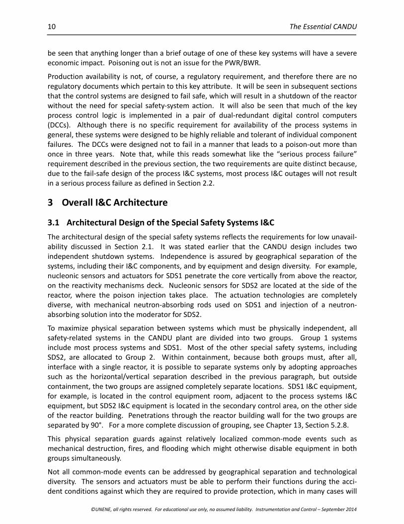
The plant can be operated in two modes, as specified by the operator, the choice being repre-sented by the position of the A/N (alternate/normal) switch shown in Figure 1:
1. In Normal mode, the operator specifies a plant electrical output in megawatts. In thismode, the UPR logic adjusts the governor valves supplying steam to the turbine to main-tain the specified electrical output. The BPC function monitors boiler pressure, and anyerror will result in changing the requested reactor power set-point which is sent fromBPC to RRS.
2. In Alternate mode, the operator specifies the reactor power output, in percentage of fullpower, and a manoeuvring rate. The alternate mode set-point is then moved to meetthis request at the specified rate. RRS sets the reactor power, which determines the en-ergy delivered by the primary heat-transport system to the boilers. BPC then manipu-lates the turbine governor valves to maintain boiler pressure at a fixed set-point. BPCalso has control of the condenser and atmospheric steam discharge valves, which can beopened to receive steam if the turbine load is lost, thus isolating the remainder of thesystem from abrupt changes in generator load and permitting continued reactor opera-tion without the turbine as a load, thus avoiding a reactor shutdown due to buildup ofXe135.
Instrumentation and Control
©UNENE, all rights reserved. For educational use only, no assumed liability. Instrumentation and Control – September 2014
15
Figure 1 CANDU overall plant control
4.1 RRS control logic
RRS control logic in CANDU accomplishes the following:
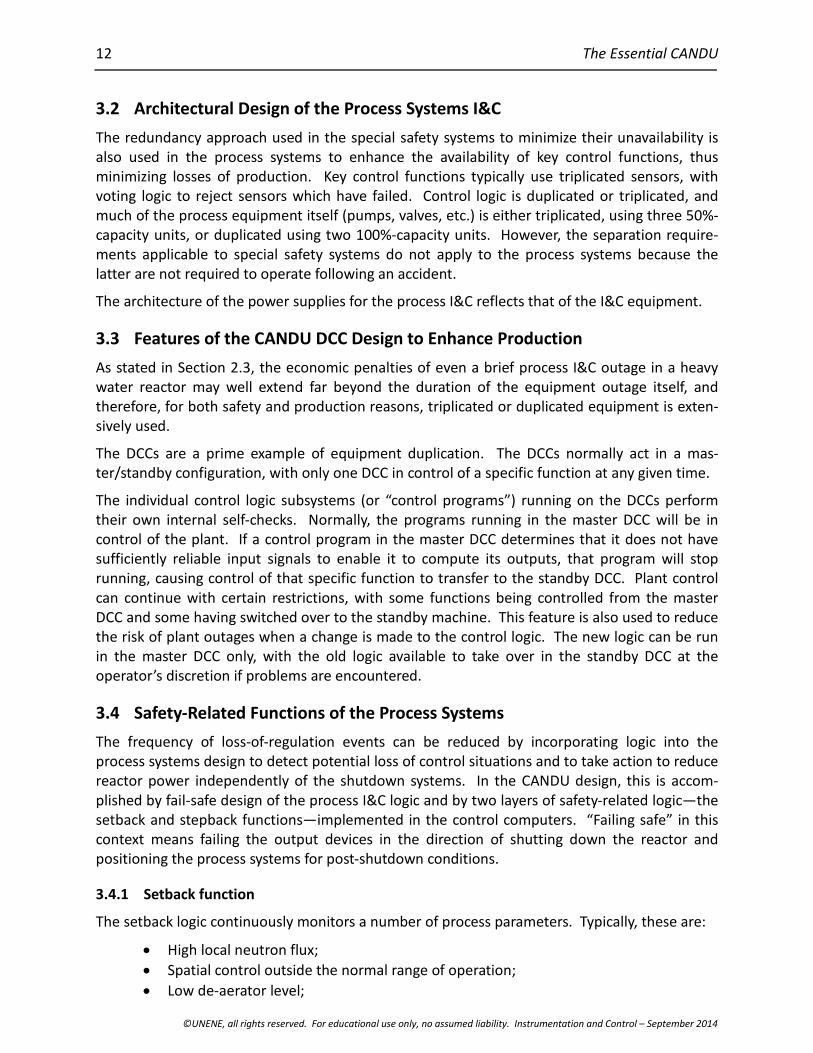
1. Because the CANDU core is relatively large and subject to spatial instability due tothe dynamic action of Xe135, it has been found necessary to divide the reactor into 14zones for control purposes (see Figure 2, which shows the arbitrarily labelled “A” and“C” ends of the reactor). There are seven zones at each end of the reactor core.
Figure 2 Arrangement of the 14 control zones
The power measurement and calibration logic determines the current reactor powerin each of these zones, based on the readings provided by 28 platinum-clad Inconel®
16 The Essential CANDU
©UNENE, all rights reserved. For educational use only, no assumed liability. Instrumentation and Control – September 2014
flux detectors (two in each zone) that penetrate the reactor vertically from the reac-tivity mechanisms deck. The flux power is estimated for each of these 14 zones.
Because the platinum-clad Inconel detectors (see Section 6.1.1) do not provide anabsolute value for neutron power, the zone power estimates have to be calibratedagainst thermal power. This is determined from measurements of temperature risebetween the reactor inlet and outlet headers at low power, and from secondary-sidemeasurements of steam flow, feed-water flow, and feedwater temperature at higherpower (> 70%), because boiling in the channels renders the primary-side measure-ments unreliable at these power levels.
2. The appropriate power set-point is selected based on plant mode (Normal/Alternate,see Section 4). This set-point will be overridden if a setback is required (see Section3.4). In this event, the reactor control mode is automatically switched to alternatemode, and the power set-point is ramped down to a predetermined endpoint. If theoperator presses the HOLD POWER button on the RRS panel, automatic adjustmentof the power set-point will also be suspended.
3. The demand power logic compares the overall reactor power measured in item (1)above with the required set-point and generates a power error signal Ep, which be-comes the basis for the control of the reactivity mechanisms described next.
Note that internally RRS works with logarithmic power, expressed in decades. This isappropriate because the reactor is a multiplicative device and the reactivity-controlmechanisms control the rate of neutron multiplication. The reactivity mechanismsare driven based on Ep, which is also a logarithmic variable, measured in decades.However, in many explanations, and indeed in the displays seen by the operator, theEp axis is labelled as “Power Error %” (see, for example, Figure 3). What is implied isthat the value is a percentage of current power, not of full power.
4. During normal steady-state operation, the reactivity in each of the 14 zones is ma-nipulated by adjusting the level of light water in each of 14 cylindrical compartments,one located in each zone (see Figure 2). In a heavy water reactor, light water is aneutron absorber. Each of the 14 compartments has a fixed outflow and a valvewhich controls the inflow of light water. These valves are manipulated in response toa combination of the overall power error, Ep, and any deviation of zone flux from theaverage over all 14 zones. The total worth of all 14 light water zones is about 7 mk.The logic to control overall power is run twice per second. Tilt control is updatedevery two seconds.
In a zone where the overall error and the spatial components of the error signal sumto zero, inflow will equal outflow, and the light water level will remain constant atsome intermediate level. The level of light water in each zone does not contribute tovalve opening. However, as the level approaches either completely full or com-pletely empty, the controlled variable changes from zone power to light water levelso that the zones never completely flood or drain. These light water zone controllersare described in Section 6.2.
5. If more negative reactivity is required than the liquid zones are able to provide, asindicated by the zones becoming close to full, then this is accomplished by the me-

Instrumentation and Control
©UNENE, all rights reserved. For educational use only, no assumed liability. Instrumentation and Control – September 2014
17
chanical control absorber logic, which drives banks of neutron-absorbing rods intothe core. These absorber rods are normally located outside the core above the reac-tor. There are four mechanical control absorbers, with a total worth of 11 mk. Theswitching logic for them is shown in Figure 3.
Figure 3 Absorber-rod drive switching
6. Similarly, when there is a lack of positive reactivity, the adjuster control logic canwithdraw banks of adjuster rods from the core (see Figure 4). These rods normallyreside in the core. There are 21 adjuster rods arranged in seven banks, with a totalworth of 15 mk. All adjusters in a given bank are driven simultaneously, but only onebank is driven at a time.
Figure 4 Adjuster-rod drive switching
The speed at which adjuster and absorber rods are driven is determined by a vari-able-frequency power supply and is a function of power error, as shown in Figure 5.
Figure 5 Rod drive speed
Once drive of either adjuster or absorber rods is started, it proceeds to completion toavoid large top-bottom flux tilts.
The absorber rods also incorporate clutches, similar to those used on the SDS1 shut-down rods. When a stepback is required, these clutches are disengaged, allowing

18 The Essential CANDU
©UNENE, all rights reserved. For educational use only, no assumed liability. Instrumentation and Control – September 2014
the absorbers to fall into the core under gravity. In this way, a much faster power re-duction is achieved than if the rods were driven electrically.
In the long term, if the light water zones tend to move significantly away from the50%-full point, the operator can adjust the available reactivity by adding poison to orremoving poison from the moderator.
4.2 BPC Control Logic
During operation at significant power levels, the goal of BPC is to maintain a constant, prede-termined boiler pressure. The BPC program also incorporates logic to handle the warming upand cooling down of the plant, but this will not be discussed here in the interests of brevity.
In Normal mode, BPC will pass a power set-point to RRS to maintain constant boiler pressuredespite possible variations in the steam taken by the turbine. Hence, the reactor is said tofollow the turbine in this mode. The set-point includes proportional and integral terms basedon pressure error.
If boiler pressure becomes excessive, BPC can manipulate a combination of condenser steamdischarge valves (CSDVs) and atmospheric steam discharge valves (ASDVs) to control boilerpressure. The CSDVs cause steam to bypass the turbine and go straight to the condenser. TheASDVs discharge steam directly to the atmosphere.
In Alternate mode, BPC also controls the steam fed to the turbine by manipulating the turbinegovernor. In this mode, the reactor power set-point is specified by the operator, and the result-ing thermal power generates steam in the boilers. The objective of BPC is to maintain constantboiler pressure. Any deviation in boiler pressure will result in the governor valves being ma-nipulated to maintain boiler pressure, and hence the reactor is said to lead the turbine in thismode. The algorithm in this case uses proportional and derivative terms based on pressureerror, plus a feed-forward term based on the rate of change of reactor power.
In addition to manipulating the governor, BPC drives the turbine load limiter, which reads thecurrent load set-point and drives the load limiter to a point 100 MW above this value.
4.3 UPR Control Logic
When the plant is operating in Normal mode, UPR manoeuvres the turbine load towards thetarget load specified by the operator. It maintains a variable LR (load reference), which isramped towards the target load at a rate which is also chosen by the operator. The actualturbine load is compared to this load reference, and the turbine speeder and load limiter areadjusted accordingly.
In Alternate mode, UPR has no control function. It fulfils a monitoring role only.
5 Special Safety Systems Functionality
The four CANDU special safety systems will now be described.
5.1 Shutdown Systems 1 and 2
Safety analysis determines a safe operating envelope for the plant. The values of a number ofplant parameters are then monitored in each shutdown-system channel to confirm that this

Instrumentation and Control
©UNENE, all rights reserved. For educational use only, no assumed liability. Instrumentation and Control – September 2014
19
envelope has not been exceeded. If any parameter exceeds a predefined trip set-point, then thechannel votes for a reactor trip. To guard against modelling errors, the CANDU design uses twodiverse parameters in each shutdown system where practical to protect against each postulatedinitiating event. The case of impracticality has been invoked in the regional overpower protec-tion (ROP) logic, which provides the primary defence against a slow loss-of-regulation accident.The ROP sensors use the same technology in both SDS1 and SDS2, and there is no backupnucleonic parameter for a slow loss of regulation, although the heat-transport high-pressureparameter does provide some protection in this case. The log-rate trip provides some diversityfor fast LORs.
Most of the parameters that trip the shutdown systems are sensed using conventional processinstrumentation, which provides fairly accurate indications of process values. However, in theregional overpower detection function, the platinum-clad Inconel sensors provide a much lessdirect indication of the physical parameter of interest: the onset of dryout in each bundle in thecore. The logic used in the ROP trip will be described in Section 7, after the limitations of thesensors used have been introduced in Section 6.1.1.
5.2 Emergency Core Cooling System
The purpose of the Emergency Core Cooling System (ECCS) is to provide an alternate means ofcooling the fuel when a loss-of-coolant accident (LOCA) has occurred. For a discussion of LOCAsof various degrees of severity, see Chapter 13, Section 5.4.
Emergency cooling occurs in two phases:
1. The ECCS monitors heat-transport system pressure and initiates high-pressure coolantinjection whenever this pressure drops below the set-point. Valves are opened, whichresults in light water being forced into the reactor inlet and outlet headers, using pres-surized helium as the motivating force. This is followed by a medium-pressure coolantinjection phase in which light water from the dousing tank becomes the source of cool-ant.
2. When the supply of light water is exhausted, low-pressure recovery is initiated. This in-volves collecting spilled liquid from the reactor-building sump and recirculating it intothe core through the reactor inlet and outlet headers. Both medium pressure and lowpressure coolant injection are effected by pumps powered by Class III electrical power.
The sensors and logic used by the ECCS are conventional, but must of course be qualified tofunction in a LOCA environment.
5.3 Containment System
For a full description of the containment system, see Chapter 13, Section 5.5. The containmentitself is the envelope designed to contain any release of radioactive material. In normal opera-tion, it is maintained at sub-atmospheric pressure by vacuum pumps which exhaust to theatmosphere through a filtration system. Following a significant release within the reactorbuilding, which is detected by high pressure, radiation, or both, the containment must beisolated. Any ensuing rise in reactor-building pressure is limited to facilitate the task of keepingleakage within allowed limits. On detection of a release, the containment is isolated by meansof dual valves or dampers incorporated in every line or duct that penetrates the containmentenvelope. The dampers isolate the reactor building ventilation ducts and are pneumatically
20 The Essential CANDU
©UNENE, all rights reserved. For educational use only, no assumed liability. Instrumentation and Control – September 2014
operated. Examples are the ventilation ducts, the spent fuel port, and the feed-water andsteam lines.
The pressure rise is limited by the dousing system. In the upper area of the building, a dousingtank contains water which is released as a spray to condense steam resulting from a heat-transport system or steam-line break. Dousing is initiated by opening a combination of electri-cally activated and pneumatically actuated valves located beneath the dousing tank. Seriesvalves are used to minimize the probability of inadvertent dosing actuation. Diverse actuationsources enhance the probability that dousing will occur when required. (This applies to single-unit CANDU stations. Multi-unit stations use a vacuum building common to all four units. Inthe event of a LOCA, the affected containment is connected to this vacuum building, and thesteam emanating from the LOCA site is doused there).
A cooling system limits the temperature rise within containment, thus maintaining the integrityof the building in the long term. The cooling system I&C is conventional. A hydrogen ignitionsystem ignites any free hydrogen gas before concentrations can become high enough to behazardous.
6 I&C Systems Layout and Equipment
In everything that has been said up to this point, the reader may have gained the impressionthat operation of the nuclear unit is entirely automatic. In the short term (up to about 30minutes), this is indeed the intent of the design. Experience has shown, however, that there is arole in plant operation for both automated and human control. Humans are not particularlygood at performing repetitive, routine tasks without error, and of course most of the controlloops involved are simply too fast and have too many interactions with other loops for a humanoperator to be involved in controlling the loop in real time. However, the human operator hasproved to have useful capabilities when things depart from the routine, where perhaps the stateof the plant is not completely clear, and when available information is either incomplete orconflicting. He can then assume an overview role and direct the progression of events towardsa stable conclusion. To do this, he has to be involved in the operation of the plant in a supervi-sory role and be presented with available information in a useful way.
The control room is the centralized point for reactor operation. A geographically separatesecondary control area is provided to shut down the plant and to provide monitoring of thoseparameters which confirm safe shutdown following the event, should the main control roombecome uninhabitable. The Group 2 I&C equipment is located in this area.
The chief operator’s station in the CANDU control room is the operator’s desk, shown in Figure6. A separate shift supervisor’s office is also provided, but he is not immediately involved in unitoperation. The operator’s desk is equipped with video display units (VDUs) driven by the DCCs.The operator can select from a large number of displays which provide information on thestatus of various systems.

Instrumentation and Control
©UNENE, all rights reserved. For educational use only, no assumed liability. Instrumentation and Control – September 2014
21
Figure 6 Layout of a CANDU 6 control room
Behind the operators’ desk are a number of panels designed for stand-up operation. Thesepanels are organized by system:
1. Containment2. SDS #23. Emergency core cooling4. SDS #15. Moderator6. Reactor regulation7. Primary heat-transport system8. Steam generators9. Turbine10. Electrical panels11. Fuel handling.
Figure 7 shows a view of the CANDU 6 control room, looking from behind the operator’s desk.This figure shows a somewhat more modern version of the control room than that depicted inFigure 6. In the centre of the group of stand-up panels are two panels containing large videodisplays used to display the overall status of the plant. Above these displays are two largemonitors which present annunciation information.

22 The Essential CANDU
©UNENE, all rights reserved. For educational use only, no assumed liability. Instrumentation and Control – September 2014
Figure 7 Pictorial view, CANDU 6 control room
At the top of each function panel is a matrix of alarm windows, some of which are driven by theDCCs and some of which are hard-wired to so-called “contact alarm units” in the conventionalcontrol logic. These are used to provide system-specific indications of alarm conditions andinclude essential alarms which will be needed should the control computers fail. The stand-uppanels themselves contain a mixture of conventional operating controls (switches, lights,meters, and dedicated PID controllers) and VDUs and keyboards interfaced to the DCCs.
Virtually all CANDU stations have been retrofitted with safety-system monitoring computers togive the operator warning of diminishing margin to trip. These computers monitor bufferedsignals from the shutdown systems and have a dedicated VDU on the operator’s desk. Thisenables the operator to take steps to avert a reactor trip. For example, the introduction of newfuel can result in an unanticipated reduction in ROP trip margin during refuelling operations.The trip-monitoring computer alerts the operator, who can then manually reduce the RRS set-point if the margin becomes uncomfortably small.
The CANDU 6 control room uses a “dark panel” approach. When no lights are visible, things arenormal.
Behind the control panels is the control equipment room, housing the physical I&C for Group 1I&C equipment (see Figure 6). Separate equipment rooms are provided for the DCCs.
The detailed control logic for each system is subject to change in the early design stages of anew nuclear plant, and therefore a means has been devised to enable much of the requiredequipment to be installed before these details are available. Much of the logic equipment, aswell as the sensors and actuators, can be installed and wired to the control distribution frame(CDF) before details of the interconnecting logic are known. The interconnection logic is imple-mented later by wiring discrete connecting wires at the CDF. The CDF is, in effect, a giantjunction box about two metres high and several tens of metres long and is a major feature inthe CANDU control-equipment room (see Figure 6).
Sensors are typically located close to the parameters being measured. This results in a large
Instrumentation and Control
©UNENE, all rights reserved. For educational use only, no assumed liability. Instrumentation and Control – September 2014
23
number of sensors being located within containment, although the electronics may still beseparated from the sensor elements to facilitate maintenance. The electrical signals are takenthrough the containment wall by penetrations which are designed to preclude leaks from withincontainment along the cables.
Actuators are likewise close to the process equipment being controlled. They may use electricalpower directly or use electrical/pneumatic converters in the case of loads driven by instrumentair. Most of the electrical loads are driven by switchgear located in the turbine building.
6.1 Sensors
For the most part, the I&C systems use sensors that are used in other process control applica-tions. However, because the subject of this text is a nuclear reactor, a description of the sensorsused for measuring neutron flux is presented below, with particular emphasis on the in-core fluxdetectors, which are unique to the CANDU reactor. To ensure the necessary independence, thesensors used by each special safety system are dedicated to the system in question and areseparate from the sensors, wiring, and associated equipment used by the process systems.
6.1.1 Neutron flux sensors
When starting up and operating a nuclear reactor, it is necessary to measure neutron powerover a very wide range, of the order of 10 decades. During start-up, special neutron countersare used to monitor neutron flux as poison is removed from the moderator using ion exchange.After a prolonged shutdown, special fission chambers are also used temporarily. At approxi-mately 10-7 x full power, ion chambers located outside the reactor core come on-scale. In theCANDU reactor, control is transferred to the DCCs at this point, and the neutron counters areremoved. The ion-chamber readings provide a logarithmic reading of neutron power, which RRSuses for control up to around one decade below full power.
In an ion chamber, two concentric boron-coated cylinders capture thermal neutrons. Theresulting alpha emissions cause ionization of hydrogen gas in the space between the cylinders.A high voltage is applied between the cylinders, which captures electrons caused by this ioniza-tion. The resulting current (~100 μA at full power) is amplified and provides signals proportional to bulk linear, logarithmic, and log-rate power which are usable over a wide range (10-7 to 1.5 xfull power).
In the last decade, between 10% and 100% power, the thermal power in the fuel itself is thevariable of interest. A prompt measurement of spatial power is required because any control orshutdown action must take place before local fuel damage can occur. Unlike most processvariables, there is no single instrument that provides even a close approximation to the powerin each channel of the CANDU core. Yet it is crucial to be able to determine this power becausethe thermal power in each channel determines the point at which dryout will start to occur.Thermal power is closely related to neutron flux, and therefore determining the latter providesa good estimate of the former.
Neutron flux within the core varies continually, even when the reactor is at constant power, dueto the rather slow oscillations (in the order of hours) in the distribution of Xe135 throughout thecore and to local flux peaks resulting from online refuelling. Although it is not possible tocontrol flux down to the location of a few fuel bundles, it is feasible to control flux tilts betweenthe 14 reactor zones. To do this, the flux in each of these zones must be measured locally.
24 The Essential CANDU
©UNENE, all rights reserved. For educational use only, no assumed liability. Instrumentation and Control – September 2014
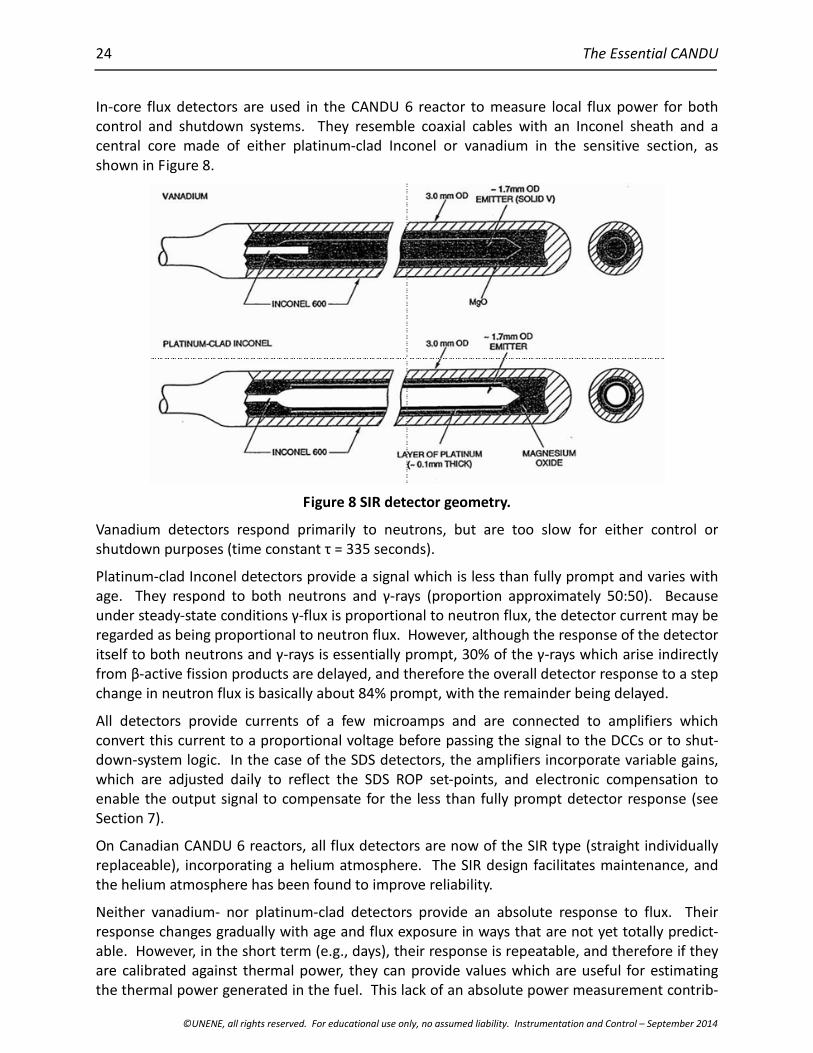
In-core flux detectors are used in the CANDU 6 reactor to measure local flux power for bothcontrol and shutdown systems. They resemble coaxial cables with an Inconel sheath and acentral core made of either platinum-clad Inconel or vanadium in the sensitive section, asshown in Figure 8.
Figure 8 SIR detector geometry.
Vanadium detectors respond primarily to neutrons, but are too slow for either control orshutdown purposes (time constant τ = 335 seconds).
Platinum-clad Inconel detectors provide a signal which is less than fully prompt and varies withage. They respond to both neutrons and γ-rays (proportion approximately 50:50). Because under steady-state conditions γ-flux is proportional to neutron flux, the detector current may be regarded as being proportional to neutron flux. However, although the response of the detectoritself to both neutrons and γ-rays is essentially prompt, 30% of the γ-rays which arise indirectly from β-active fission products are delayed, and therefore the overall detector response to a step change in neutron flux is basically about 84% prompt, with the remainder being delayed.
All detectors provide currents of a few microamps and are connected to amplifiers whichconvert this current to a proportional voltage before passing the signal to the DCCs or to shut-down-system logic. In the case of the SDS detectors, the amplifiers incorporate variable gains,which are adjusted daily to reflect the SDS ROP set-points, and electronic compensation toenable the output signal to compensate for the less than fully prompt detector response (seeSection 7).
On Canadian CANDU 6 reactors, all flux detectors are now of the SIR type (straight individuallyreplaceable), incorporating a helium atmosphere. The SIR design facilitates maintenance, andthe helium atmosphere has been found to improve reliability.
Neither vanadium- nor platinum-clad detectors provide an absolute response to flux. Theirresponse changes gradually with age and flux exposure in ways that are not yet totally predict-able. However, in the short term (e.g., days), their response is repeatable, and therefore if theyare calibrated against thermal power, they can provide values which are useful for estimatingthe thermal power generated in the fuel. This lack of an absolute power measurement contrib-
Instrumentation and Control
©UNENE, all rights reserved. For educational use only, no assumed liability. Instrumentation and Control – September 2014
25
utes significantly to the complexity of both the ROP protection and power control algorithms. Adetailed explanation of this is beyond the scope of this text.
The flux detectors used and their locations are as follows:
102 vanadium detectors are inserted vertically from the reactivity mechanism deck.These are used by the flux mapping program in the DCCs. The vanadium detectorsare also the basis for the setback on high local neutron flux (see Section 3.4.1)
28 platinum-clad Inconel detectors (two for each of the 14 zones) are inserted verti-cally from the reactivity mechanism deck. In each zone pair, one is in channel A andone in channel C. These are used by the RRS program, the flux mapping program,and the stepback program in the DCCs.
34 platinum-clad Inconel detectors are inserted vertically from the reactivity mecha-nism deck. These are used by SDS1. The detectors are divided between channels D,E, and F.
24 platinum-clad Inconel detectors are inserted horizontally and are used by SDS2.The detectors are divided between channels G, H, and J. Future builds are expectedto require the same number of detectors as for SDS1.
6.1.2 Other sensors
Most process analog signals are transmitted using 4-20 mA current loops (to help minimize theinfluence of electrical noise) from the point of measurement to the central control area. Tem-peratures are measured using resistance temperature detectors (RTDs) and to a limited extentthermocouples.
Given the large ground currents to be expected in generating stations, particular care is neededin sensor wiring to ensure that electrical noise and offset voltages do not corrupt these analogsignals.
Contact sensing in the CANDU design uses 48VDC logic, although 24VDC is more common inmodern process control equipment. This relatively high voltage has been found to minimizeproblems with degraded field contacts.
Although some I&C systems have been replaced at various sites with more modern digitalequipment, there are still very few, if any, instances in CANDU plants of sensors which use digitalcommunication right from the point of measurement. Because the individual stations maketheir own design decisions about equipment replacement, they would have to be consulted foraccurate information in this regard.
6.2 Actuators
Actuators in CANDU are primarily electrically driven by on/off 48VDC outputs from the controlsystem logic. Small loads may be driven directly, while heavy loads are driven by motor controlcentres which receive their inputs as 48VDC signals. Some larger valves are pneumaticallyactuated by electrical-to-air converters, and therefore in addition to the electrical supplysystem, there is an instrument air system with odd and even channels. Because this system isnot described elsewhere, an overview of it is included in Section 6.2.1. Air-driven valves cantypically move much more rapidly than electrically driven ones. For example, on CANDU, largeair-driven valves are used to isolate containment. Air-driven valves typically use local air accu-mulators to provide a local power source following loss of the main air supply. This power can
26 The Essential CANDU
©UNENE, all rights reserved. For educational use only, no assumed liability. Instrumentation and Control – September 2014
be used to drive air-driven actuators to a predetermined safe position following such an event.
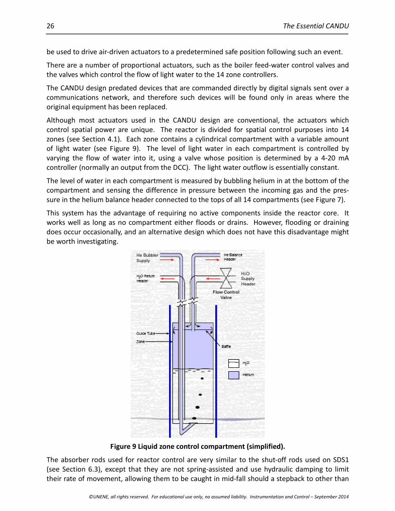
There are a number of proportional actuators, such as the boiler feed-water control valves andthe valves which control the flow of light water to the 14 zone controllers.
The CANDU design predated devices that are commanded directly by digital signals sent over acommunications network, and therefore such devices will be found only in areas where theoriginal equipment has been replaced.
Although most actuators used in the CANDU design are conventional, the actuators whichcontrol spatial power are unique. The reactor is divided for spatial control purposes into 14zones (see Section 4.1). Each zone contains a cylindrical compartment with a variable amountof light water (see Figure 9). The level of light water in each compartment is controlled byvarying the flow of water into it, using a valve whose position is determined by a 4-20 mAcontroller (normally an output from the DCC). The light water outflow is essentially constant.
The level of water in each compartment is measured by bubbling helium in at the bottom of thecompartment and sensing the difference in pressure between the incoming gas and the pres-sure in the helium balance header connected to the tops of all 14 compartments (see Figure 7).
This system has the advantage of requiring no active components inside the reactor core. Itworks well as long as no compartment either floods or drains. However, flooding or drainingdoes occur occasionally, and an alternative design which does not have this disadvantage mightbe worth investigating.
Figure 9 Liquid zone control compartment (simplified).
The absorber rods used for reactor control are very similar to the shut-off rods used on SDS1(see Section 6.3), except that they are not spring-assisted and use hydraulic damping to limittheir rate of movement, allowing them to be caught in mid-fall should a stepback to other than

Instrumentation and Control
©UNENE, all rights reserved. For educational use only, no assumed liability. Instrumentation and Control – September 2014
27
zero power be required,
The adjuster rods have no rapid movement capability. The winches that control their positionare driven by electric motors connected to a variable-frequency supply.
6.2.1 Instrument Air System
Pneumatically operated valves are very common in the process control industry in general.These valves include on/off and continuous control valves and are typically commanded by anelectrical signal. Compressed air for these valves is supplied by the Instrument Air System, aservice system which, in a manner somewhat analogous to the electrical system described inChapter 11, distributes compressed air to the numerous end-user devices throughout the plant.Like the electrical system, the instrument air system provides channelized sources and distribu-tion paths to ensure that the appropriate degree of redundancy and separation is available. Thecompressed air provides a powerful force multiplier, and operation of the end devices also tendsto be relatively fast. The requirements for both instrument air and electrical power systems arecovered in a common document [CSA2011b].
This description will concentrate on the reactor-building instrument air system because it is ofgreatest interest in terms of nuclear safety and reliability. Within the reactor building, there areabout 130 on/off valves and around 70 continuous-action control valves powered by instrumentair. Prominent among the former are the valves which initiate liquid poison injection for shut-down system #2, the dousing valves, the containment isolation dampers, and the moderatortemperature-control valves, all of which play significant roles in ensuring plant safety. Thereactor-building instrument air system is seismically qualified.
Refer to the greatly simplified schematic in Figure 10.
Figure 10 Reactor building instrument air system (simplified).
During normal plant operation, the reactor-building instrument air system receives its supply ofcompressed air from the same bank of compressors that provide instrument air for the remain-der of the plant. These are located in the turbine hall and run off Class 3 electrical power, sothat air supply is subject to interruption for a five-minute period in the event of a loss of Class 4
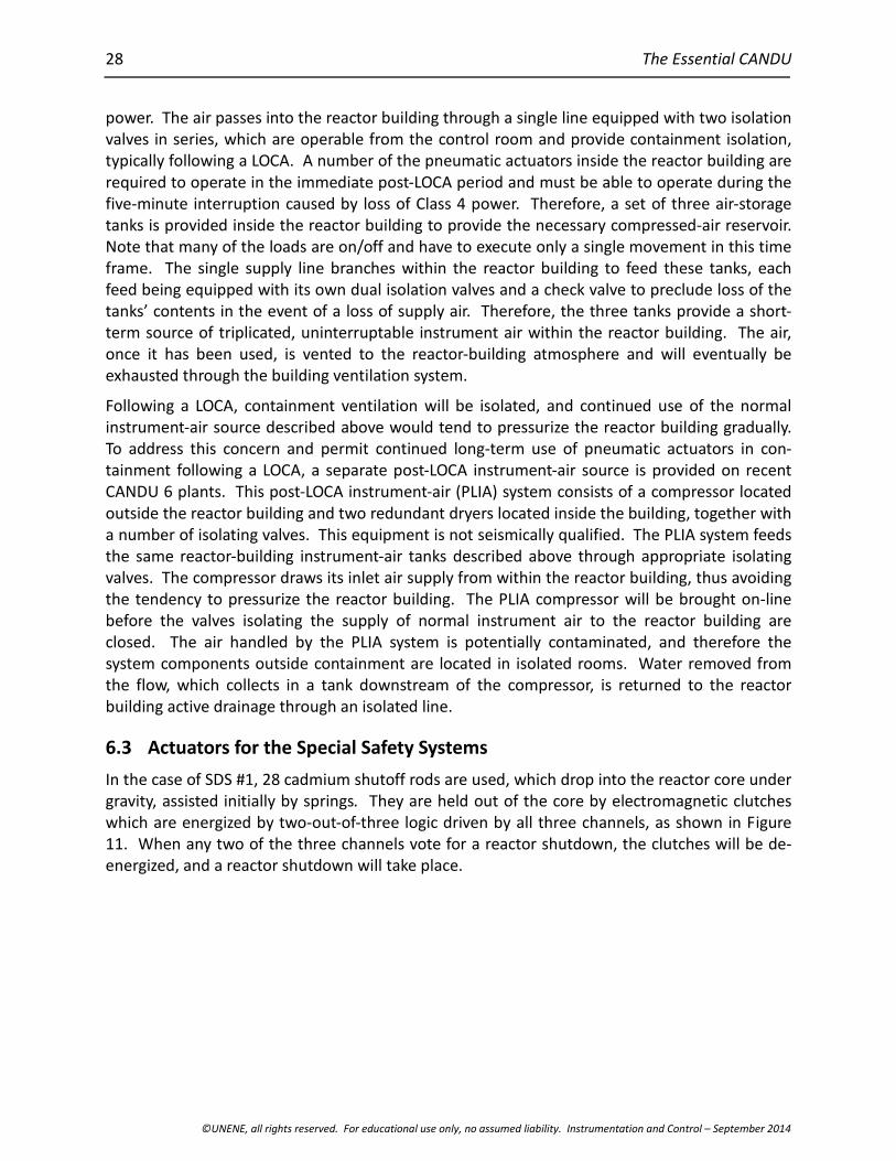
28 The Essential CANDU
©UNENE, all rights reserved. For educational use only, no assumed liability. Instrumentation and Control – September 2014
power. The air passes into the reactor building through a single line equipped with two isolationvalves in series, which are operable from the control room and provide containment isolation,typically following a LOCA. A number of the pneumatic actuators inside the reactor building arerequired to operate in the immediate post-LOCA period and must be able to operate during thefive-minute interruption caused by loss of Class 4 power. Therefore, a set of three air-storagetanks is provided inside the reactor building to provide the necessary compressed-air reservoir.Note that many of the loads are on/off and have to execute only a single movement in this timeframe. The single supply line branches within the reactor building to feed these tanks, eachfeed being equipped with its own dual isolation valves and a check valve to preclude loss of thetanks’ contents in the event of a loss of supply air. Therefore, the three tanks provide a short-term source of triplicated, uninterruptable instrument air within the reactor building. The air,once it has been used, is vented to the reactor-building atmosphere and will eventually beexhausted through the building ventilation system.
Following a LOCA, containment ventilation will be isolated, and continued use of the normalinstrument-air source described above would tend to pressurize the reactor building gradually.To address this concern and permit continued long-term use of pneumatic actuators in con-tainment following a LOCA, a separate post-LOCA instrument-air source is provided on recentCANDU 6 plants. This post-LOCA instrument-air (PLIA) system consists of a compressor locatedoutside the reactor building and two redundant dryers located inside the building, together witha number of isolating valves. This equipment is not seismically qualified. The PLIA system feedsthe same reactor-building instrument-air tanks described above through appropriate isolatingvalves. The compressor draws its inlet air supply from within the reactor building, thus avoidingthe tendency to pressurize the reactor building. The PLIA compressor will be brought on-linebefore the valves isolating the supply of normal instrument air to the reactor building areclosed. The air handled by the PLIA system is potentially contaminated, and therefore thesystem components outside containment are located in isolated rooms. Water removed fromthe flow, which collects in a tank downstream of the compressor, is returned to the reactorbuilding active drainage through an isolated line.
6.3 Actuators for the Special Safety Systems
In the case of SDS #1, 28 cadmium shutoff rods are used, which drop into the reactor core undergravity, assisted initially by springs. They are held out of the core by electromagnetic clutcheswhich are energized by two-out-of-three logic driven by all three channels, as shown in Figure11. When any two of the three channels vote for a reactor shutdown, the clutches will be de-energized, and a reactor shutdown will take place.
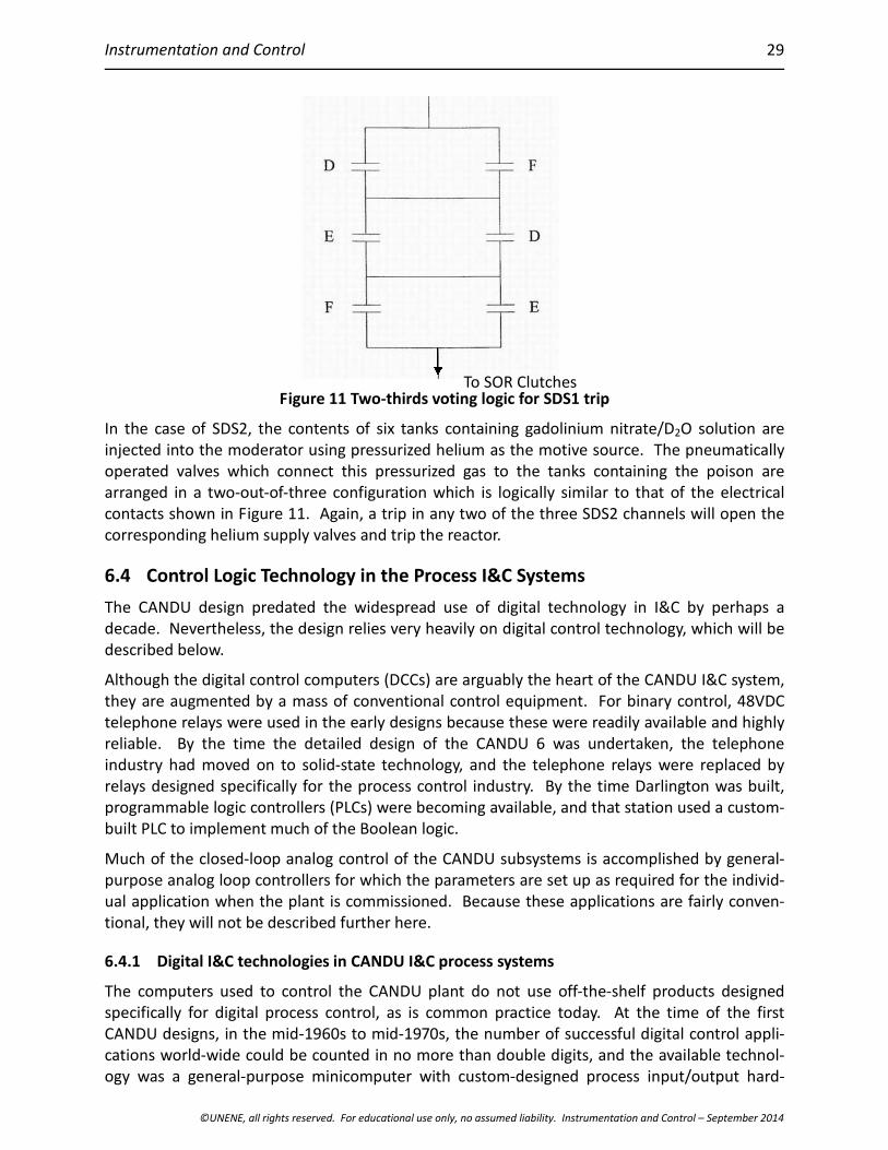
Instrumentation and Control
©UNENE, all rights reserved. For educational use only
29
Figure 11 Two-thirds vot
In the case of SDS2, the contents of six tanks coinjected into the moderator using pressurized heoperated valves which connect this pressurizedarranged in a two-out-of-three configuration whcontacts shown in Figure 11. Again, a trip in anycorresponding helium supply valves and trip the r
6.4 Control Logic Technology in the Proce
The CANDU design predated the widespread usdecade. Nevertheless, the design relies very heavdescribed below.
Although the digital control computers (DCCs) arethey are augmented by a mass of conventional ctelephone relays were used in the early designs breliable. By the time the detailed design of thindustry had moved on to solid-state technologyrelays designed specifically for the process contrprogrammable logic controllers (PLCs) were becombuilt PLC to implement much of the Boolean logic
Much of the closed-loop analog control of the CApurpose analog loop controllers for which the parual application when the plant is commissioned.tional, they will not be described further here.
6.4.1 Digital I&C technologies in CANDU I&C pr
The computers used to control the CANDU planspecifically for digital process control, as is comCANDU designs, in the mid-1960s to mid-1970s,cations world-wide could be counted in no moreogy was a general-purpose minicomputer with
, no assumed liability. Instrumentation and Control – September 2014
ing logic for SDS1 trip
ntaining gadolinium nitrate/D2O solution arelium as the motive source. The pneumatically
gas to the tanks containing the poison areich is logically similar to that of the electricaltwo of the three SDS2 channels will open the
eactor.
ss I&C Systems
e of digital technology in I&C by perhaps aily on digital control technology, which will be
arguably the heart of the CANDU I&C system,ontrol equipment. For binary control, 48VDCecause these were readily available and highlye CANDU 6 was undertaken, the telephone, and the telephone relays were replaced by
ol industry. By the time Darlington was built,ing available, and that station used a custom-
.
NDU subsystems is accomplished by general-ameters are set up as required for the individ-Because these applications are fairly conven-
ocess systems
t do not use off-the-shelf products designedmon practice today. At the time of the firstthe number of successful digital control appli-than double digits, and the available technol-custom-designed process input/output hard-
To SOR Clutches
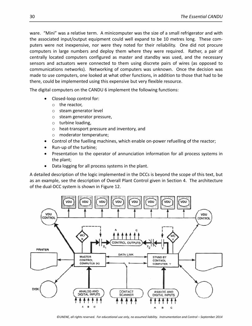
30 The Essential CANDU
©UNENE, all rights reserved. For educational use only, no assumed liability. Instrumentation and Control – September 2014
ware. “Mini” was a relative term. A minicomputer was the size of a small refrigerator and withthe associated input/output equipment could well expand to be 10 metres long. These com-puters were not inexpensive, nor were they noted for their reliability. One did not procurecomputers in large numbers and deploy them where they were required. Rather, a pair ofcentrally located computers configured as master and standby was used, and the necessarysensors and actuators were connected to them using discrete pairs of wires (as opposed tocommunications networks). Networking of computers was unknown. Once the decision wasmade to use computers, one looked at what other functions, in addition to those that had to bethere, could be implemented using this expensive but very flexible resource.
The digital computers on the CANDU 6 implement the following functions:
Closed-loop control for:o the reactor,o steam generator levelo steam generator pressure,o turbine loading,o heat-transport pressure and inventory, ando moderator temperature;
Control of the fuelling machines, which enable on-power refuelling of the reactor;
Run-up of the turbine;
Presentation to the operator of annunciation information for all process systems inthe plant;
Data logging for all process systems in the plant.
A detailed description of the logic implemented in the DCCs is beyond the scope of this text, butas an example, see the description of Overall Plant Control given in Section 4. The architectureof the dual-DCC system is shown in Figure 12.
Instrumentation and Control
©UNENE, all rights reserved. For educational use only, no assumed liability. Instrumentation and Control – September 2014
31
Figure 12 CANDU 6 DCC architecture
All the software was written in assembly language. Although this ensured that the software wasas compact and as fast as possible, the result was a program that relied totally on the program-mer for its integrity and which was not directly reviewable by other than software cognoscenti.
6.4.1.1 Annunciation and status display
In addition to the inputs needed by the software which controls the plant, several hundredanalog and contact inputs are connected to the DCCs to enable alarm information to be pre-sented to the operator and to provide him with status information on the various systems, usingthe VDU controllers and printers shown in Figure 12.
Alarms are generated within the control logic when abnormal conditions are detected. Theseconditions are detected either by hardware logic in the control equipment or by tests built intothe DCC control software. The alarms are presented to the operator using a combination ofilluminated “windows” above the control panels and DCC-driven VDUs in the central area of thestand-up panel. In addition to the alarms generated by the control functions resident in theDCCs, the computers monitor thousands of contact and analog signals, enabling their alarms tobe displayed on the VDUs and recorded on a printed log in chronological sequence.
The CANDU alarm annunciation system works well for routine operation and for minor plantdisturbances. One can imagine, however, that during major plant disturbances (e.g., loss ofClass IV power), the operator is faced with a sudden flood of alarm messages, flashing windows,and horn tones. When Class IV power is lost, many subsystems will no longer be available andwill initiate an alarm in consequence, but all that the operator really needs to know is the majorevent: loss of Class IV power. To mitigate this situation, the CANDU alarm-annunciation schemeuses some very basic prioritization logic. Each alarm is designated as “major” or “minor”. Whencertain predefined plant upset conditions are in progress, minor alarms are temporarily sup-pressed on the VDUs. Although this does help, there is no doubt that a more intelligent alarmpresentation system would be useful. Such schemes have been contemplated in the past andwill probably be incorporated in any new CANDU build, but progress has been slow because theconditions under which it is appropriate to suppress any given alarm typically require verycareful examination of the operation of the systems involved, meaning that the construction ofthe database behind such a system would be very labour-intensive. This would appear to be anideal application for some kind of expert system. However, there is great reluctance to imple-ment any system whose response to a given plant upset is not completely deterministic. Theapproach to such intelligent annunciation systems has always been very conservative. One canimagine the repercussions if it were determined in some post-event investigation that suppres-sion of a particular alarm had resulted in incorrect operator action.
6.4.1.2 Fuelling-machine control
The on-line refuelling function is unique to the CANDU design. On the CANDU 6 stations,fuelling-machine control is implemented in the DCCs. On many of the Ontario 4 unit stations,this function has separate, dedicated computer controls provided by the fuelling-machinevendor, but again, minicomputer technology is used. Unlike the closed-loop process-systemcontrol discussed earlier, control of the fuelling machines is an example of sequential control.The computer carries out a step in a sequence and then checks that the expected feedbackindications have been returned from the plant before moving on to the next step. Each step
32 The Essential CANDU
©UNENE, all rights reserved. For educational use only, no assumed liability. Instrumentation and Control – September 2014
consists of a single predefined action and a set of post-action checks. A job is made up of aseries of steps. Jobs may be executed automatically from start to finish or may progress onestep at a time under operator supervision. In any event, if the expected feedbacks do notmaterialize, execution stops, and the operator is alerted.
The sequential actions required to complete each fuelling activity (i.e., a “job”) are defined in aninterpretive language developed specifically for the CANDU fuelling application. Although notas readable as a modern sequential control language, this language does provide the readerwith some level of isolation from the underlying assembly-language logic. The operator canallow the job to proceed entirely automatically or can elect to require his permission betweeneach step and the next.
Because fuelling is not required on a continuous basis, the fuelling-machine function is onlyimplemented in a single DCC.
6.4.2 Historical perspective
As an indication of how the technology has changed in 40 years, the CANDU 6 DCCs had 64Kbytes of memory and a one-megabyte disc drive. The central processor cycle time was aroundone microsecond. To maximize performance, the machines were programmed in assemblylanguage. Every byte of software was custom developed. A previously developed operatingsystem was not used, for example. The result is a system which, although very flexible, requiresoutdated skills to maintain and is also particularly prone to errors in software maintenance.However, all attempts to migrate to more modern equipment have been rejected because ofthe financial consequences of any delays or errors in implementation of a replacement system.Although aging DCC equipment has been replaced, changes have been made at the individualhardware module level, with custom replacements being engineered to match the fit, form, andfunction of the old equipment, and particularly to have minimal impact on the existing soft-ware. The DCC equipment does not support the standard techniques which have evolved overthe years for the development of highly reliable computer systems. Standards such as[CANDU1999] would be applied to the systems and software engineering of any new-builddesign. The replacement of the DCC platform is undoubtedly one of the greatest challengesfacing the designers of a new-build CANDU.
6.5 Logic Technology in the Special Safety Systems
On all CANDUs before the CANDU 6, the algorithms for making the trip decision were imple-mented entirely in hardware (primarily by analog comparators). This tends to mean that thetrip set-points for each parameter are constant values because implementation of set-pointswhich are themselves functions of another plant variable becomes rather complex.
6.5.1 Digital I&C technologies in CANDU 6 shutdown systems
With the need to have two diverse trip parameters for each postulated accident, it becamedifficult to identify suitable parameters with fixed set-points without imposing a large penaltyon reactor power or incurring an increased frequency of unnecessary reactor trips. The decisionwas made to use set-points for some process trip parameters that were functions of other plantvariables, notably reactor power. Means of generating these set-points using analog electronichardware were examined, but ultimately the decision was made to implement the trip logic forprocess trips (i.e., trips not based on reactor power measurement) using digital computers.
Instrumentation and Control
©UNENE, all rights reserved. For educational use only, no assumed liability. Instrumentation and Control – September 2014
33
They were not, however, called computers, but were referred to as “programmable digitalcomparators” (PDCs).
6.5.2 Digital I&C technologies in Darlington shutdown systems
Given the success of the PDCs on the CANDU 6, the decision was made on Darlington to gofurther. Not only would both nucleonic and process trips be implemented in computers, butseparate computers would be added to support automated testing of the shutdown systems.Darlington would be the first reactor in the world to feature completely digital shutdown-systemlogic. In recognition of this, the term “PDC” was dropped. At Darlington, the equipment wascalled “trip computers”. It was recognized that additional steps would have to be taken toensure high quality in the software engineering which implemented the trip logic. What wasnot recognized was just how onerous this process would become.
In the ten years that elapsed between CANDU 6 and Darlington, the software industry hadmatured immensely, and computers were being used to an increasing degree in applicationsinvolving public safety. The experience had not been entirely positive. Lives had been lost as aresult of software errors. In fact, one of the landmark case studies cited in software engineeringtexts involved a radiation-therapy machine engineered by AECL which resulted in several deathsbefore the software design errors were identified and corrected. Interested readers can Googlethe “Therac-25”.
When the design of the Darlington shutdown-system software was undertaken, it was recog-nized that there was a problem, but the appropriate systems engineering standards had not yetbeen written that would establish acceptable ways to address the problem. The Darlingtonshutdown systems became a stepping stone in the development of these standards, but theprogram encountered serious delays and cost overruns. A product of this effort was a series ofstandards written by AECL and Ontario Hydro governing the engineering of software for safety-related applications at various levels of criticality [CANDU1999].
The international safety-related systems industry has since introduced a standard which isapplicable not only to software development, but also to systems engineering of safety-relatedsystems using digital technology in general [IEC2001a]. A derivative of this standard applicablespecifically to the nuclear industry also exists [IEC2001b], but it has yet to be broadly adoptedby the Canadian nuclear industry.
Despite the early experience at Darlington, the end result is a system that is well regarded byoperating and regulatory staff.
7 Regional Overpower (ROP) Trip Logic
Description of the ROP logic has been deferred to this point to enable the characteristics of thesensors involved to be discussed before describing how these are accommodated in the design.The following discussion is applicable to both SDS1 and SDS2.
The CANDU 6 ROP systems currently have 34 and 24 flux detectors in shutdown systems 1 and 2respectively. Hence, there are only 8 to 12 detectors per channel, yet each channel is requiredto protect against fuel dryout in any one of the 380 channels in the core. As discussed inSection 6.1.1, the detector signals represent only point values in the distribution of fluxthroughout the core. Moreover, the outputs decline with age and are not completely prompt.
34 The Essential CANDU
©UNENE, all rights reserved. For educational use only, no assumed liability. Instrumentation and Control – September 2014
The trip comparator associated with each ROP detector is set to a value determined offline by acomputer code “ROVER” to ensure that at least two detectors in each SDS will call for a tripbefore dryout occurs at any location in the core. The computer code considers a large numberof normal and abnormal reactor configurations, but does not account for non-equilibriumfuelling. Typically, with new pressure tubes, this comparator set-point will be around 122%,although it declines as the pressure tubes age. The code is re-run and the comparators areadjusted infrequently (e.g., once every three years) to account for changes that affect thermalhydraulics, such as pressure-tube creep. The comparator setting includes the desired margin totrip.
The RFSP (Reactor Fuelling Simulation Program) code is run frequently (e.g., once every threedays). It synthesizes a flux map based on the reactor’s power and fuelling history, on reactivitymechanism positions, and on the 102 vanadium detector readings. The power in each channel jin the channel-power peaking factor region (all but the outer extremity of the core), CPj, is thencomputed and divided by the reference power for that channel, CPref j, to yield the normalizedchannel power:
Pnorm j = CPj/CPref j.
The highest Pnorm j becomes the channel-power peaking factor (CPPF, typically around 1.08).Therefore, the CPPF represents the worst-case power peaking factor due to refuelling rippleover all channels. The detector amplifier gains are then adjusted so that they read (currentreactor power x CPPF). It can be seen that this approach is quite conservative because itassumes that all detectors will be affected equally by the channel at greatest risk. This purposeof this calibration is to compensate for changes in position of the reactivity mechanisms and forlocal flux changes due to fuelling. It also incidentally compensates for decreasing detectorsensitivity with age. Typically, one or two detectors per channel will be found to be out of limitsin any particular adjustment cycle.
Each detector amplifier also includes two filters which compensate for the non-prompt re-sponse of the detector itself. These are not normally adjusted. The compensated signals passedto the comparators represent a fairly close approximation to the thermal power in the fuel,which is what causes dryout, and hence is the signal on which the reactor needs to be tripped.The effect of this compensation is shown in Figure 13.
The set-points for both SDS1 and SDS2 are based on the same criteria, including trip margins,and therefore it is a matter of chance which system will trip first. Indeed, in the case of a slowLOR, it is likely that SDS2 will trip first because it has fewer detectors and hence its set-pointsmust be somewhat more conservative. In the past, there was an incentive to arrange things sothat SDS1 would trip first because it could be re-poised much more quickly and potentially avoida reactor poison-out. Nowadays, the analysis associated with restarting the reactor after anytrip is sufficiently time-consuming that a poison-out is inevitable in either case.

Instrumentation and Control
©UNENE, all rights reserved. For educational use only, no assumed liability. Instrumentation and Control – September 2014
35
Figure 13 Effect of compensation on Pt-clad detector response
Clearly, there are many uncertainties involved in determining the trip set-points, both in thecomparator settings determined by ROVER and in the calibration of the detectors to account forCPPF. Typical uncertainties are:
simulation uncertainties
detector uncertainties
uncertainties specific to a given SDS channel
common uncertainties
CCP uncertainties
refuelling uncertainties
uncertainties due to the effects of moderator poison.
These uncertainties are combined statistically and incorporated into the comparator settings,the intent being to ensure that at least one detector in each SDS channel will trip in a givenshutdown system before dryout occurs, 98% of the time,. As noted in Section 7, two channelsmust trip before a reactor trip occurs. The CANDU 6 and Ontario reactors use different methodsof justifying compliance with this 98% criterion, but achieve similar results.
Uncertainty in any trip set-point results in its being assigned a conservative value. In the case ofROP set-points, this results directly in a loss of plant capacity, and therefore any improvement inunderstanding the uncertainties is likely to result in higher trip set-points, which will have animmediate economic payoff. Even a 1% increase, for example, results in an increased powercapacity of 60,000 MWh per year for a 600-MW station. Depending on the going rate forpower, that is worth several millions of dollars every year.
8 Design Verification
All CANDU systems were subject during the design process to a design review carried out bytheir designers’ peers. This review was based on the detailed design documentation producedfor the customer. With each succeeding design generation, the documentation became morecomprehensive. However, the process-systems review was never based on the detailed com-prehensive list of system requirements which is typical of best-practice systems design in amodern engineering context.
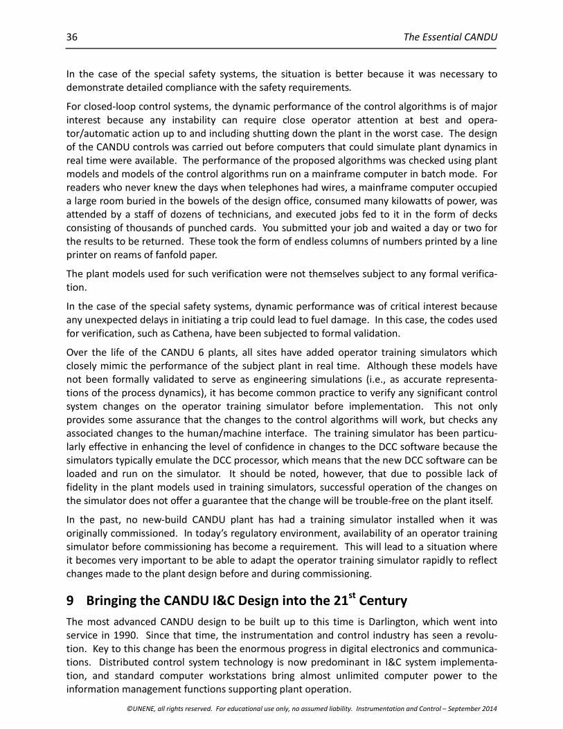
36 The Essential CANDU
©UNENE, all rights reserved. For educational use only, no assumed liability. Instrumentation and Control – September 2014
In the case of the special safety systems, the situation is better because it was necessary todemonstrate detailed compliance with the safety requirements.
For closed-loop control systems, the dynamic performance of the control algorithms is of majorinterest because any instability can require close operator attention at best and opera-tor/automatic action up to and including shutting down the plant in the worst case. The designof the CANDU controls was carried out before computers that could simulate plant dynamics inreal time were available. The performance of the proposed algorithms was checked using plantmodels and models of the control algorithms run on a mainframe computer in batch mode. Forreaders who never knew the days when telephones had wires, a mainframe computer occupieda large room buried in the bowels of the design office, consumed many kilowatts of power, wasattended by a staff of dozens of technicians, and executed jobs fed to it in the form of decksconsisting of thousands of punched cards. You submitted your job and waited a day or two forthe results to be returned. These took the form of endless columns of numbers printed by a lineprinter on reams of fanfold paper.
The plant models used for such verification were not themselves subject to any formal verifica-tion.
In the case of the special safety systems, dynamic performance was of critical interest becauseany unexpected delays in initiating a trip could lead to fuel damage. In this case, the codes usedfor verification, such as Cathena, have been subjected to formal validation.
Over the life of the CANDU 6 plants, all sites have added operator training simulators whichclosely mimic the performance of the subject plant in real time. Although these models havenot been formally validated to serve as engineering simulations (i.e., as accurate representa-tions of the process dynamics), it has become common practice to verify any significant controlsystem changes on the operator training simulator before implementation. This not onlyprovides some assurance that the changes to the control algorithms will work, but checks anyassociated changes to the human/machine interface. The training simulator has been particu-larly effective in enhancing the level of confidence in changes to the DCC software because thesimulators typically emulate the DCC processor, which means that the new DCC software can beloaded and run on the simulator. It should be noted, however, that due to possible lack offidelity in the plant models used in training simulators, successful operation of the changes onthe simulator does not offer a guarantee that the change will be trouble-free on the plant itself.
In the past, no new-build CANDU plant has had a training simulator installed when it wasoriginally commissioned. In today’s regulatory environment, availability of an operator trainingsimulator before commissioning has become a requirement. This will lead to a situation whereit becomes very important to be able to adapt the operator training simulator rapidly to reflectchanges made to the plant design before and during commissioning.
9 Bringing the CANDU I&C Design into the 21st Century
The most advanced CANDU design to be built up to this time is Darlington, which went intoservice in 1990. Since that time, the instrumentation and control industry has seen a revolu-tion. Key to this change has been the enormous progress in digital electronics and communica-tions. Distributed control system technology is now predominant in I&C system implementa-tion, and standard computer workstations bring almost unlimited computer power to theinformation management functions supporting plant operation.
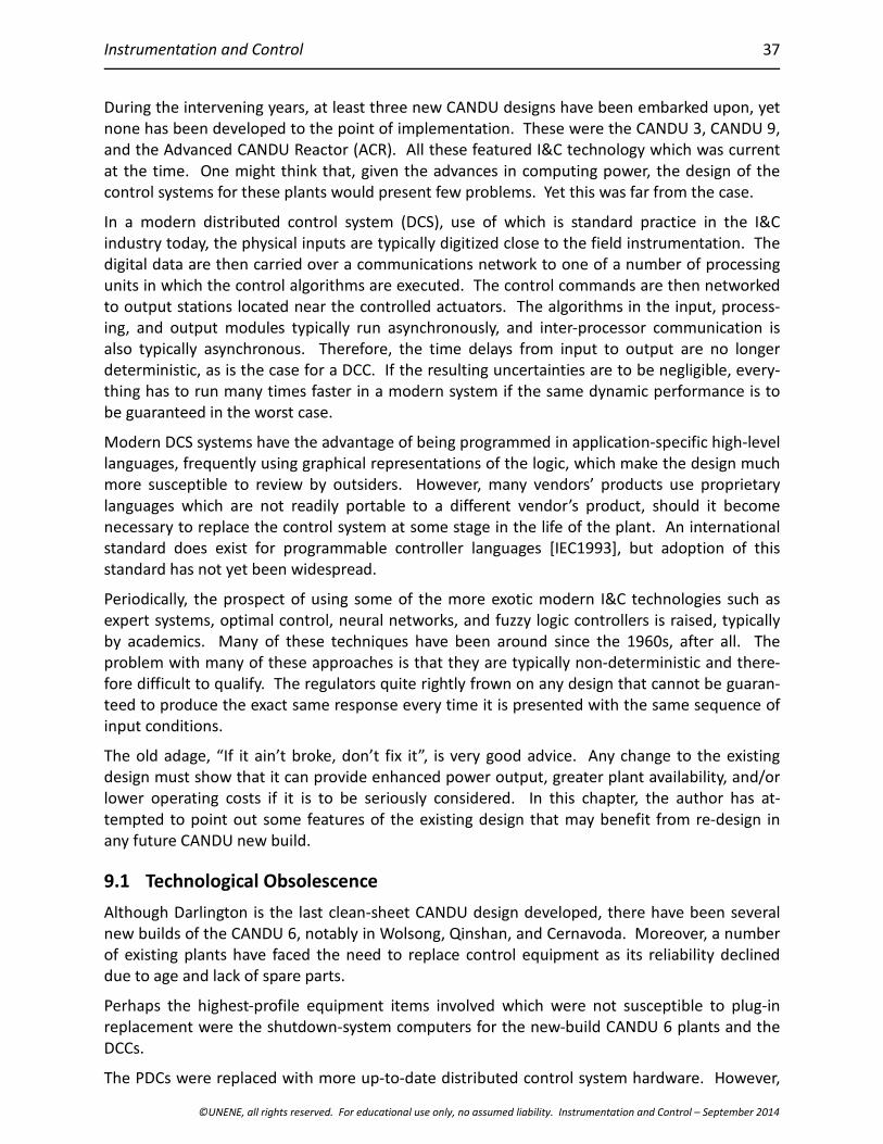
Instrumentation and Control
©UNENE, all rights reserved. For educational use only, no assumed liability. Instrumentation and Control – September 2014
37
During the intervening years, at least three new CANDU designs have been embarked upon, yetnone has been developed to the point of implementation. These were the CANDU 3, CANDU 9,and the Advanced CANDU Reactor (ACR). All these featured I&C technology which was currentat the time. One might think that, given the advances in computing power, the design of thecontrol systems for these plants would present few problems. Yet this was far from the case.
In a modern distributed control system (DCS), use of which is standard practice in the I&Cindustry today, the physical inputs are typically digitized close to the field instrumentation. Thedigital data are then carried over a communications network to one of a number of processingunits in which the control algorithms are executed. The control commands are then networkedto output stations located near the controlled actuators. The algorithms in the input, process-ing, and output modules typically run asynchronously, and inter-processor communication isalso typically asynchronous. Therefore, the time delays from input to output are no longerdeterministic, as is the case for a DCC. If the resulting uncertainties are to be negligible, every-thing has to run many times faster in a modern system if the same dynamic performance is tobe guaranteed in the worst case.
Modern DCS systems have the advantage of being programmed in application-specific high-levellanguages, frequently using graphical representations of the logic, which make the design muchmore susceptible to review by outsiders. However, many vendors’ products use proprietarylanguages which are not readily portable to a different vendor’s product, should it becomenecessary to replace the control system at some stage in the life of the plant. An internationalstandard does exist for programmable controller languages [IEC1993], but adoption of thisstandard has not yet been widespread.
Periodically, the prospect of using some of the more exotic modern I&C technologies such asexpert systems, optimal control, neural networks, and fuzzy logic controllers is raised, typicallyby academics. Many of these techniques have been around since the 1960s, after all. Theproblem with many of these approaches is that they are typically non-deterministic and there-fore difficult to qualify. The regulators quite rightly frown on any design that cannot be guaran-teed to produce the exact same response every time it is presented with the same sequence ofinput conditions.
The old adage, “If it ain’t broke, don’t fix it”, is very good advice. Any change to the existingdesign must show that it can provide enhanced power output, greater plant availability, and/orlower operating costs if it is to be seriously considered. In this chapter, the author has at-tempted to point out some features of the existing design that may benefit from re-design inany future CANDU new build.
9.1 Technological Obsolescence
Although Darlington is the last clean-sheet CANDU design developed, there have been severalnew builds of the CANDU 6, notably in Wolsong, Qinshan, and Cernavoda. Moreover, a numberof existing plants have faced the need to replace control equipment as its reliability declineddue to age and lack of spare parts.
Perhaps the highest-profile equipment items involved which were not susceptible to plug-inreplacement were the shutdown-system computers for the new-build CANDU 6 plants and theDCCs.
The PDCs were replaced with more up-to-date distributed control system hardware. However,

38 The Essential CANDU
©UNENE, all rights reserved. For educational use only, no assumed liability. Instrumentation and Control – September 2014
due to the relatively small amount of logic involved and the fact that the PDCs are not geo-graphically distributed, the new design was able to avoid reliance on digital communications.Architecturally, then, the new PDCs were little different from the systems they replaced. Thefunctions of the safety-critical software running on the existing equipment were re-engineeredfor the new platforms. Although this re-engineering was by no means a trivial task, the exis-tence of well-documented requirements and accepted procedures [CANDU1999] for carryingout this work made it fairly routine.
The replacement approach for the DCC hardware took a very different approach. The obviousapproach to DCC replacement is to use a modern DCS, as discussed in the previous section.However, DCC replacement has the potential to lead to a very protracted and costly plantoutage if anything goes wrong during the replacement or if the software implementation provesto have defects once the plant is brought back online. To minimize this risk, the fundamentalrequirement of the plant owners has been to replicate the existing control logic in precise detail.
The existing DCCs contain a large body of purpose-designed software, ranging from the operat-ing system to dozens of applications whose details are specific to each CANDU site. The mostreliable definition of the functionality of this software is the program listing itself, which iswritten in a machine-specific assembly language.
As stated in the introduction, the design and implementation of the analog control loopsimplemented in the DCCs are based on classical frequency-domain techniques. At a detail level,the control logic consists of an interconnected set of gain elements, integrators, and differenti-ators. However, because these elements are ultimately implemented in assembly language andare specified in the form of difference equations, the basic structure of the control logic is farfrom obvious to anybody reviewing the detailed design. Translating the existing control logicinto the context of a modern DCS platform with a high degree of confidence that the platformchange will not introduce latent errors would be a formidable task. Not only is there a risk oferrors in the interpretation of the software functionality, but the different architectures of thetwo platforms make emulation of real-time performance very difficult to guarantee.
Therefore, if a DCS were used to replace these DCCs, the DCC logic would have to be reverse-engineered and a new DCS-based design developed and re-validated from the ground up. Noplant owner or CANDU 6 replication project manager has accepted this risk. The alternative wasto custom-build replacement computer equipment which would be fit-, form-, and function-compatible with the existing hardware and which would host the existing software with rela-tively minor changes.
As it happened, the CANDU industry was not the only one to be confronted with this problem,and replacement computer hardware based on more modern components had been developedfor both the Pickering A and CANDU 6 DCCs. These “clone” computers served as a starting pointfor the refurbishment of these units, a process which is still ongoing.
All this means that all existing CANDUs will run with aging I&C technology for the next couple ofdecades and that the first CANDU new build, should there be one, will be the proving ground forthe design, licensing, and implementation of what is now standard practice for the I&C industry,assuming that the “clone” DCC is not retained.
The design life of a CANDU plant is around 40 years. With refurbishment, this could well extendto 70 years or more. Each generation of I&C technology becomes obsolete in about 15 years,

Instrumentation and Control
©UNENE, all rights reserved. For educational use only, no assumed liability. Instrumentation and Control – September 2014
39
particularly if one is speaking about digital equipment. The manufacturers of the equipmenttypically will not guarantee to support their product beyond about 20 years, though if onehappens to pick a particularly successful product line, this date might be extended by another10 years. Therefore, any nuclear plant will have to face replacement of its digital I&C equipmentat least twice in the lifetime of the plant. In the case of the original CANDU DCCs, the originalequipment was specifically developed in Canada by a custom systems integration supplier whoowned much of the design data and was able to purchase the rest from the original equipmentmanufacturers. Manufacturers of off-the-shelf I&C products are not interested in this kind of re-engineering business. However, by far the most economic and reliable solution in the futurewill be to base the I&C on off-the-shelf equipment. Design for replacement has not so far beena requirement on next-generation reactors. This is a challenge that should be accepted. Theexisting refurbished CANDU plants will probably have to face this issue with their DCCs at leastonce more during their extended lifetimes because it is hard to imagine the present vendor stillproviding support in 2040. In future replacements, it is unlikely that development of a replace-ment platform which can run the existing software will be practical, and therefore the issue ofrewriting the software when the equipment is replaced will have to be faced. If a hardwareplatform which supports the industry-standard languages [IEC1993]is used, this offers somehope that the existing software will be portable. However, the industry in general has shownlittle inclination to adopt these languages, meaning that there is no guarantee that this ap-proach will yield the desired advantages.
10 Summary of Relationship to Other Chapters
By this point, the reader will be aware that the architectural design of the control systems isheavily dependent on the safety requirements that these systems implement, and on thenecessity to avoid unnecessary interruptions of the plant’s raison d’être – the production ofelectrical power. Chapter 13 provides an excellent description of the safety requirements, andshould be read in conjunction with the material presented herein.
Chapter 5 provides a discussion of the reactor physics, including the control actuators which theRRS and shutdown systems use to control reactor flux.
I&C systems are only as good as the motive power sources that drive them—in the case ofCANDU, primarily Class I and II electrical power and instrument air. The design of the electricalpower distribution system is presented in Chapter 11. A brief description of the instrument airsystem is included in Section 6.2.1 of the present chapter.
11 Problems
1. Starting with an equilibrium reaction, assume that a control rod is moved out of core bya fixed distance. What form will the curve of reactor power vs. time assume?
2. Given the approximate numbers quoted in Section 2 and assuming that the light-waterzone controllers are initially half full, in the absence of any other control or shutdown ac-tion, what value would the power in a CANDU reactor reach in one second if all the light-water zone controllers suddenly drained? Assume that initial power = 100% and that thetotal reactivity worth of the zone controllers = 7 mk.
3. From the point of view of reliability, why is it important in a reactor with two shutdownsystems that the two systems be independent?
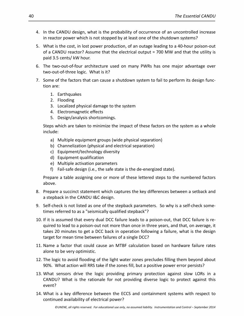
40 The Essential CANDU
©UNENE, all rights reserved. For educational use only, no assumed liability. Instrumentation and Control – September 2014
4. In the CANDU design, what is the probability of occurrence of an uncontrolled increasein reactor power which is not stopped by at least one of the shutdown systems?
5. What is the cost, in lost power production, of an outage leading to a 40-hour poison-outof a CANDU reactor? Assume that the electrical output = 700 MW and that the utility ispaid 3.5 cents/ kW hour.
6. The two-out-of-four architecture used on many PWRs has one major advantage overtwo-out-of-three logic. What is it?
7. Some of the factors that can cause a shutdown system to fail to perform its design func-tion are:
1. Earthquakes2. Flooding3. Localized physical damage to the system4. Electromagnetic effects5. Design/analysis shortcomings.
Steps which are taken to minimize the impact of these factors on the system as a wholeinclude:
a) Multiple equipment groups (wide physical separation)b) Channelization (physical and electrical separation)c) Equipment/technology diversityd) Equipment qualificatione) Multiple activation parametersf) Fail-safe design (i.e., the safe state is the de-energized state).
Prepare a table assigning one or more of these lettered steps to the numbered factorsabove.
8. Prepare a succinct statement which captures the key differences between a setback anda stepback in the CANDU I&C design.
9. Self-check is not listed as one of the stepback parameters. So why is a self-check some-times referred to as a "seismically qualified stepback"?
10. If it is assumed that every dual DCC failure leads to a poison-out, that DCC failure is re-quired to lead to a poison-out not more than once in three years, and that, on average, ittakes 20 minutes to get a DCC back in operation following a failure, what is the designtarget for mean time between failures of a single DCC?
11. Name a factor that could cause an MTBF calculation based on hardware failure ratesalone to be very optimistic.
12. The logic to avoid flooding of the light water zones precludes filling them beyond about90%. What action will RRS take if the zones fill, but a positive power error persists?
13. What sensors drive the logic providing primary protection against slow LORs in aCANDU? What is the rationale for not providing diverse logic to protect against thisevent?
14. What is a key difference between the ECCS and containment systems with respect tocontinued availability of electrical power?

Instrumentation and Control
©UNENE, all rights reserved. For educational use only, no assumed liability. Instrumentation and Control – September 2014
41
15. What would be some key requirements for the secondary control area?
16. It has been suggested that the control system be made capable of initiating a power set-back on low margin to trip. What possible objection could there be to such a proposal?
17. What are the potential effects of a failure of the air-conditioning system which servicesthe room housing the DCCs?
18. Why might the CDF be less relevant in the context of modern I&C technology?
19. List some pros and cons of digitizing instrument readings inside containment.
20. When using thermal measurements to calibrate flux-detector readings, what processingwill have to be applied to the flux-detector readings before they are compared to ther-mal power measurements?
21. Why are ion chambers not used for control in the upper decade (10% to 100%) of reac-tor power?
22. Why do you think digital sensors have seen limited application in retrofit projects on ex-isting CANDU power plants?
23. What would be the most demanding requirement facing a potential replacement for thelevel measurement in the light-water zone compartments? Suggest some possible tech-nologies which might be used.
24. What long-term factors might require the operator to adjust bulk reactivity using mod-erator poison?
25. What characteristics of the CANDU design drove the choice to use digital computer con-trol before it was a widely accepted technology?
26. What are some negative consequences of having the control logic defined in softwarewritten in assembly language?
27. What would be a major reason that an annunciation scheme based on expert systemtechnology might be difficult to license?
28. Give an example of a non-proprietary language which would be appropriate to the defi-nition of sequential control logic.
29. List some advantages to making shutdown-system testing an automatic function.
30. List two reasons why software is often considered to be particularly prone to design er-rors.
31. Which ROP adjustment accounts for the changing shape of flux within the reactor core?
32. Why will the ROP trip comparator set-points need to be adjusted downwards as thepressure tubes age?
33. Give an example of a non-proprietary language which would be appropriate to the defi-nition of (a) analog and (b) Boolean control logic.
34. In what way does the architecture of a distributed control system, as opposed to that ofa centralized computer system, affect the execution timing of the control logic?

42 The Essential CANDU
©UNENE, all rights reserved. For educational use only, no assumed liability. Instrumentation and Control – September 2014
12 References
[Rouben2002] Rouben, B. Introduction to Reactor Physics, Atomic Energy of Canada Ltd., Sep-tember 2002.
[Rouben2008] Rouben, B., Reactivity Coefficients, McMaster University course EP 4D03/6D03,September 2008.
[AECB1977] AECB. Regulatory Document R-10: The Use of Two Shutdown Systems in Reactors,AECB, January 11, 1977.
[AECB1991a] AECB. Regulatory Document R-8, Requirements for Shutdown Systems for CANDUNuclear Power Plants, AECB, February 21, 1991.
[AECB1991b] AECB. Regulatory Document R-7, Requirements for Containment Systems forCANDU Nuclear Power Plants, AECB, February 21, 1991.
[AECB1991c] AECB. Regulatory Document R-9, Requirements for Emergency Core CoolingSystems for CANDU Nuclear Power Plants, AECB, February 21, 1991.
[CSA2011a] CSA. N290.4-11: Requirements for the Reactor Regulating Systems of Nuclear PowerPlants, Canadian Standards Association, October 2011.
[CSA2011b] CSA N290.5-06: Requirements for Electrical Power and Instrument Air Systems ofCANDU Nuclear Power Plants.
[CANDU1999] CANDU. Standard for Software Engineering of Safety Critical Software, CE-10010STD, Revision 2, CANDU Computer Systems Engineering Centre of Excellence, De-cember 1999.
[IEC2001a] IEC. IEC 61508, Functional Safety of Electrical/Electronic/Programmable ElectronicSafety-Related Systems, International Electrotechnical Commission, June 2001.
[IEC2001b] IEC. IEC 61513, Nuclear Power Plants – Instrumentation and Control for SystemsImportant to Safety – General Requirements for Systems, International ElectrotechnicalCommission, March 2001.
[IEC1993] IEC. IEC 61131-3, Programmable Controllers, Part 3: Programming Languages, Inter-national Electrotechnical Commission, March 1993.
13 Acknowledgements
The following reviewers are gratefully acknowledged for their hard work and excellent com-ments during the development of this Chapter. Their feedback has much improved it. Of coursethe responsibility for any errors or omissions lies entirely with the authors.
Werner FieguthDave FournierNorm IchiyenAlek Josefowicz
Thanks are also extended to Diana Bouchard for expertly editing and assembling the final copy.