chapter 10 multiple transducer channel sweep systems for
TRANSCRIPT

EM 1110-2-1003 1 Jan 02
Chapter 10 Multiple Transducer Channel Sweep Systems for Navigation Projects 10-1. General Scope The Corps deploys a variety of multiple-transducer channel sweep systems for clearing shallow-and deep-draft navigation projects. These systems are designed to provide 100% coverage (see Figure 10-1) of a given project site and are particularly useful in searching for and supporting clearance of hazards to navigation. They also are used for performing dredge measurement and payment surveys since their full coverage capabilities provide more-accurate quantity computations. After-dredge surveys performed with channel sweep systems are used for certifying channel grade clearance. Some districts use sweep systems for routine project condition surveys because they are useful in locating channel obstructions or “strikes.” Multiple transducer systems are mainly used on shallow draft and inland navigation projects. Their use on deep draft projects is declining due to increased reliance on multibeam technology. Since multiple transducer systems are similar in operation to single beam systems, most of the quality control and quality assurance procedures covered in the previous chapter are applicable to multiple transducer operations. Specific technical criteria for multiple transducer systems are found in Table 10-1 at the end of this chapter.
Figure 10-1. Generalized multiple transducer sweep array 10-2. Background Multiple transducer systems were first deployed in the Corps during the early 1970s. The primary goal during that time was to replace the mechanical bar sweeps used by some districts for project clearance and acceptance. Most Corps districts contracted with Ross Laboratories to develop systems with transducers mounted on side-mounted booms. Other multiple transducer systems were developed by Raytheon, Innerspace Technology, and Odom. Currently (FY 01) eight districts are operating multiple transducer systems on both shallow- and deep-draft navigation projects: Detroit, St. Louis, St. Paul, New York, Savannah, Mobile, New England, and Portland.
10-1

EM 1110-2-1003 1 Jan 02 10-3. Design of Channel Sweep Systems Channel sweep systems are simply a series of standard single beam transducers vertically mounted on a boat, barge, or other stable platform. The transducers are typically mounted boom attachments to the vessel. The number of transducers in a sweep ranges from three up to 32. Bottom coverage is a function of transducer spacing, beam width, and channel depth. Due to high resultant motion at the far end of each boom (from vessel roll), boom-sweep systems are normally effective only on calm, restricted inland waterways. These systems are used to perform both payment and project condition surveys. Boom-mounted sweep vessels normally perform longitudinal run sweep surveys in order to identify shoals for dredging.
a. Sweep width. The sweep width is determined by the type of vessel deployed and project (channel) characteristics. Typically, sweep systems are designed to cover swaths ranging from 25 ft to over 120 ft. Optimizing sweep width with vessel maneuverability is often difficult--large sweeps using boom-mounted transducers being more difficult to control. Optimizing sweep width requires consideration of vessel characteristics and local conditions.
b. Transducer configuration. Sweep systems may use any number of transducers. Two or more transducers may be mounted permanently in the vessel hull. Additional transducers may be mounted on “over-the-side” outriggers or, more commonly, from hinged, retractable booms deployed to port and starboard. The more common systems deploy between 3 and 12 transducers on combinations of hull and retractable boom mounts. Figure 10-2 depicts a typical Ross boom sweep system operated by the St. Louis district. Similar boom-mounted Ross sweep systems are deployed by the St. Paul, New York, Mobile, and Savannah districts.
Figure 10-2. Typical Ross boom sweep system (St. Louis District)
(1) A typical installation for a boom system would include one or more transducers mounted in the hull and two or more transducers mounted on each boom. Often, a five-channel system is used (1 hull, 2 port, and 2 starboard). Transducers are 208 kHz at 8-deg beam angle. Each channel has its own
10-2
EM 1110-2-1003 1 Jan 02
transmitter, receiver, and depth digitizer board. Both analog and digital depths are provided, and the multi-channel depth data is multiplexed via a single RS232 board.
(2) The port and starboard booms are retractable via hand winch. The stored position is vertical--usually against the side of the boat cabin. The individual struts mounting the transducers are designed with a breakaway feature should the strut strike a floating obstacle. The boom assemblies can be removed if necessary.
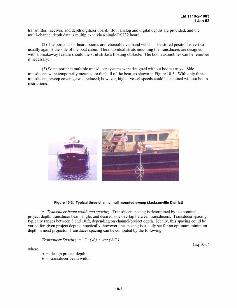
(3) Some portable multiple transducer systems were designed without boom arrays. Side transducers were temporarily mounted to the hull of the boat, as shown in Figure 10-3. With only three transducers, sweep coverage was reduced; however, higher vessel speeds could be attained without boom restrictions.
Figure 10-3. Typical three-channel hull mounted sweep (Jacksonville District)
c. Transducer beam width and spacing. Transducer spacing is determined by the nominal project depth, transducer beam angle, and desired side overlap between transducers. Transducer spacing typically ranges between 3 and 10 ft, depending on channel/project depth. Ideally, this spacing could be varied for given project depths; practically, however, the spacing is usually set for an optimum minimum depth in most projects. Transducer spacing can be computed by the following:
Transducer Spacing = 2 · ( d ) · tan ( b/2 )
(Eq 10-1) where, d = design project depth b = transducer beam width
10-3

EM 1110-2-1003 1 Jan 02 Transducer spacing (in feet) for 8 deg and 16 deg beam widths for various project depths (at 100% coverage--i.e., no overlap) are shown below. Depth (Feet)
Beamwidth 10 15 20 25 30 40 50 75
8 deg 1.4 2.1 2.8 3.5 4.2 5.6 7.0 10.5 16 deg 2.8 4.2 5.6 7.0 8.4 11.2 14.1 21.1
From the above table, a five-transducer system operating in a 10-ft inland navigation project will cover about a 15-ft swath if a 16-deg beam width is used. Larger beam width transducers may be obtained to increase coverage. Full 100% coverage is not always required on shallow-draft inland projects; thus the spacing can be adjusted for 50% to 75% coverage. Spacing may also be reduced to provide overlapping coverage (i.e., > 100%) for critical strike detection.
d. Strike detection with sweep systems. The capability for strike detection using channel sweep systems is highly dependent on the operating characteristics of the transducers and the acoustic processing system, along with coverage patterns, floating plant maneuverability, and sweep overlap. Optimum transducer spacing and beam angle are essential for strike identification given a nominal project depth. Obtaining 100% coverage with an acoustic sweep system may not provide full assurance that all potential strikes have been recovered. Many objects can deflect acoustic energy such that they are below the detection threshold of the echo sounder. Some large rock fragments can exhibit “stealth-like” acoustic characteristics to vertically mounted transducers, and thus avoid acoustic detection. In such cases, it is best practice to run overlapping swath runs that will provide 200% (or more) bottom coverage.
e. Data collection methods. Both analog and digital data recording may be utilized on these
systems. Figure 10-4 shows an analog representation from three transducers in an older Raytheon 719 CSS system operated by the Jacksonville district. Many digital display modeling techniques are now available to assist in interpretation of the large amount of recorded data, especially when 8, 16, 32 or more transducers are simultaneously operating. Vessel guidance, tracking, and data storage is performed using standard software packages containing modules for multiple transducer systems. Complete bottom coverage is assured by screen painting swath tracks similar to multibeam systems.
10-4

EM 1110-2-1003 1 Jan 02
Figure 10-4. Raytheon 719 CSS multiple transducer analog record ca 1980 (Jacksonville District) 10-4. Philadelphia District Channel Sweep System The Philadelphia District operated a ten-transducer boom-mounted Ross sweep system until 1999. It was used on deep-draft projects for clearance and dredge payment. It has recently been replaced with a multibeam system. Since this system is representative of most USACE sweep systems, a brief description of it follows.
a. Four of the 10 transducers are mounted directly to the hull of the catamaran-type survey
vessel. Six transducers are boom mounted, three to port side and three to the starboard side boom. Transducers are calibrated with a bar check monthly. Daily, a Ross ball check is performed to monitor the hull-mounted transducers. A sound velocity profile is also observed to monitor velocity changes.
b. Vessel sweep speed is normally between 3 and 6 knots. Sweep data from all transducers is
collected by time, not distance along the track line. Therefore, vessel speed must be controlled to avoid gaps. A fluxgate compass (or gyroscope) is interfaced with the data collection system to correct for yaw of the vessel and boom assembly--allowing for direct coordinate computation on each transducer. Any type of horizontal positioning system can be used--microwave and DGPS being the most common.
c. Sweep line spacings are designed for 20% side overlap. Cross-line checks may be run in order
to monitor quality control of the sweep data. Comparisons can be made using either a single transducer or full terrain models.
d. Sweep data is edited though use of the system monitor aboard the vessel. Editing and review
are made in plan or section format and the database corrected as required. Final plot scales and densities are selected depending on the nature of the project. In most instances, depth data must be selectively “thinned” for plan view plots at normal scales. Other options allow for selecting fixed cell (window) sizes for site plan plots or filtering out and plotting strikes above a preset grade.
10-5

EM 1110-2-1003 1 Jan 02
e. Cell/window size can be automatically determined -- typically 5-ft or 10-ft square. Since one
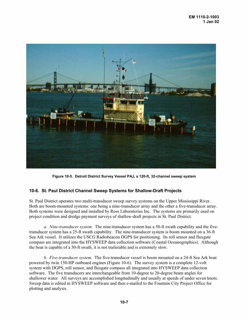
or more depths may have been recorded within a cell, different techniques are used in determining the final value displayed or in material quantity computations. Normally, either the least depth or average depth within a cell is used. This value is then shifted to the cell centroid for plotting purposes. This process for selecting, thinning, and shifting of data must be thoroughly understood by those evaluating the data relative to contract performance. 10-5. Detroit District 120-Ft Strike Detection System An Odom Echoscan multiple transducer channel sweep system used by the Detroit District (Figure 10-5) is deployed from a 200-ton, 100-ft long by 30-ft beam by 7-ft draft, self-propelled barge containing 32 separate transducers spaced 3.75 ft O/C. The transducers are mounted along a catwalk that extends 10 feet beyond each end of the vessel. This provides for a 116.25 ft length or about a 120-foot swath at typical project depth. These systems are used for strike detection in rock cut channels. Obstructions may be caused by ice jams, propeller wash, or large vessels dragging anchors that lifts and loosens rock material within the channels. The district deploys two such systems--one in Detroit and another at Sault Ste. Marie, MI. They have replaced the manual sweep rafts previously used for strike detection. Each transducer has a large enough beam width to provide overlapping coverage in typical 25- to 30-ft project depths found in the Detroit, St. Clair and St. Marys channels. The operating frequency is 214 kHz with a pulse duration of 0.1 msec. The transducers are small ceramic discs 1.55 inches in diameter. The transducer beam width is 12 deg at -3dB and 17 deg at the -6 dB power points. Transducers are individually calibrated using standard bar check devices supplemented with velocity probe data and ball-check methods. A 32-foot calibration bar is employed in order to check every transducer Calibration is also performed in a lock chamber at the Soo Locks where 30-ft checks can be obtained. Each transducer has separate draft and sound velocity settings. This type of vessel usually works in conjunction with a crane barge (derrick boat) for removing loose rock and other debris within navigation projects. (1) The vessels are propelled by two Schottell, 360-deg, hydraulically operated rudder propellers, one at each end of the vessel. They are driven by 240 HP engines. The vessels have no keel so all direction and movement is dependent on the rudder-propeller system. The vessels are controlled by the direction and amount of thrust from the rudder-propeller. The vessel is navigated to work sites as any 130-ft long vessel. The rudder is manually controlled and a handwheel from each rudder-propeller with arrows indicating thrust direction allows the boat operator to direct the engine's output. Throttles located in the center of the handwheel provide the thrust controls. Auxiliary power is obtained from two 30 kW generators operating at 3 phase and 480 volts. (2) The vessels are operated sideways while sweeping. The boat operator controls the vessel's speed and direction with a single handwheel and throttle. The Schottell unit's actual direction and amount of thrust is controlled by a computer interfaced to a gyrocompass and autopilot. The computer maintains alignment of the vessel at 90 degrees to the direction of survey. (3) The sweep vessels were originally positioned using Del Norte microwave range-range and range-azimuth modes. In the 1990s positioning was converted to differential GPS. Data acquisition was originally performed using Comstar Echo Scan software running on a HP 9000 computer. Processing originally required 16 hours for each 8 hours of survey data collected--requiring a 24-hour processing operation. Once PC-based HYPACK software was added in 1994, data processing time was reduced substantially. Since only "strikes" above grade are significant, processing and/or plotting of data below grade can be eliminated. (4) Original staffing on the sweep vessel in 1986 was nine persons: 3 Wage Grade vessel operators and 6 GS survey technicians. With DGPS positioning and enhanced acquisition software, this staffing was reduced to 4 persons by 1995.
10-6
EM 1110-2-1003 1 Jan 02
Figure 10-5. Detroit District Survey Vessel PAJ, a 120-ft, 32-channel sweep system
10-6. St. Paul District Channel Sweep Systems for Shallow-Draft Projects St. Paul District operates two multi-transducer sweep survey systems on the Upper Mississippi River. Both are boom-mounted systems: one being a nine-transducer array and the other a five-transducer array. Both systems were designed and installed by Ross Laboratories Inc. The systems are primarily used on project condition and dredge payment surveys of shallow-draft projects in St. Paul District.
a. Nine-transducer system. The nine-transducer system has a 50-ft swath capability and the five-transducer system has a 25-ft swath capability. The nine-transducer system is boom mounted on a 36-ft Sea Ark vessel. It utilizes the USCG Radiobeacon DGPS for positioning. Its roll sensor and fluxgate compass are integrated into the HYSWEEP data collection software (Coastal Oceanographics). Although the boat is capable of a 50-ft swath, it is not trailerable and is extremely slow.
b. Five-transducer system. The five-transducer vessel is boom mounted on a 24-ft Sea Ark boat powered by twin 150-HP outboard engines (Figure 10-6). The survey system is a complete 12-volt system with DGPS, roll sensor, and fluxgate compass all integrated into HYSWEEP data collection software. The five transducers are interchangeable from 10-degree to 20-degree beam angles for shallower water. All surveys are accomplished longitudinally and usually at speeds of under seven knots. Sweep data is edited in HYSWEEP software and then e-mailed to the Fountain City Project Office for plotting and analysis.
10-7

EM 1110-2-1003 1 Jan 02
c. Lock chamber calibration procedures. The electronics are calibrated monthly using an aluminum bar check inside a lock chamber with the gates closed. The lock floor monoliths are sounded by using a lead line or pole to make certain the monoliths have not heaved or sunk. The bar check is then used to calibrate the sounders with the depths at 5, 10, 15 and 20 feet. All transducers are then forced to read the same depths on the data collection computer. A predetermined survey line is set up in the lock chamber and both the 24-ft and 36-ft sweep boats run this line. The lines of each boat are analyzed for correct depths. If they all read the same the systems are ready for production. The Ross ball check is then calibrated at the same time for future daily or job specific use for project condition and /or payment surveys.
Figure 10-6. St. Paul District Five-Channel Ross Mini Sweep System 10-7. Mobile District Tuscaloosa Site Office Sweep Systems The Mobile District Tuscaloosa Site Office operates four multiple-transducer automated sweep survey systems (Figure 10-7) utilizing depth sounding hardware manufactured by Ross Laboratories, and HYPACK data collection and post processing software from Coastal Oceanographics. The systems are used to provide support for dredging activities and project conditions along over 700 miles of the shallow draft 9-ft x 200-ft navigation channels of the Black Warrior–Tomigbee and Alabama River Systems. Brief descriptions of the systems follow. a. General description. The Tuscaloosa Site Office Navigation Unit operates three (3) trailerable 24-ft sweep survey vessels and the 60-ft sweep survey vessel E.B. WALLACE. The three 24-ft small-boat systems have a total of five transducers with four being attached to spring-loaded strut and boom assemblies and one being mounted amidships through the hull. The small boat systems provide a 25 ft complete swath coverage of the bottom with no gaps at water depths of 17 ft while performing data collection survey operations. The E.B. WALLACE has a total of 12 transducers with 10 being mounted
10-8

EM 1110-2-1003 1 Jan 02
on spring loaded struts attached to two 30 ft hydraulically operated retractable booms and two being mounted amidships through the hull. The E.B. WALLACE provides a complete 70 ft wide swath of the river bottom with each pass of the vessel. All transducers are spaced at 5 ft intervals along the boom and operate at frequencies of 200 kHz with dual beam selectable angles of 10 and 22 deg. Each of the four vessel's electronic components is rack mounted and located in a climate controlled cabin area.
b. Survey procedures. The multi-transducer (sweep) survey systems generate accurate representations of the complete waterway bottom using depths received from multiple transducers configured for sweep survey application and electronic positioning. Data collection is performed for each assigned surveying effort by running sweep lines that are parallel to the navigation channel. This method is also known as “Mowing the lawn” or “painting the screen” and provides data coverage of the entire navigable water area or river bank to river bank survey.
c. Transducer calibration and quality control. Transducers are calibrated with daily “ball checks” using the Ross Labs lead ball check assembly. Traditional monthly bar checks are also made using steel angle iron and a calibrated chain to verify the transducer accuracy. Checks are also performed over fixed objects such as lock and dam miter sills to provide additional assurance of depth accuracy. Independent verification is also made by comparisons of hydrographic data produced with the sweep system with simultaneous collected data produced by A-E contract survey vessels.
d. Vessel positioning. Standard meter level DGPS Positioning is provided through Novatel 10 and 12 channel DGPS cards with Starlink Radio Beacon receivers providing differential correction signals from USCG broadcast sites. A KVH digital compass/roll sensor is incorporated into the data collection systems to provide heading and boom arm roll corrections.
e. Data processing. Sweep data in digital format is recorded and stored onto 3.5 inch diskette for editing and post-processing using Coastal Oceanographics HYPACK suite of software – presently the HYPACK MAX version. The data is processed into full color 30 x 42-inch plan drawings of each survey area. The finished plots consist of color filled depth contours with elevation labels. All data points collected during the sweep survey are used in the post-processing effort with various levels of data thinning being performed to achieve desired bottom mapping results.
f. Data distribution. End use of the processed data consists of not only hard copy plots but also digital dredging files and publicly available X-Y-Z data points. Contract rental dredges are given digital plans and detailed cut boxes that are displayed using government-furnished DREDGEPACK software from Coastal Oceanographics. Digital X-Y-Z data is also made available via the Tuscaloosa Homepage Internet site for FTP download by vendors desiring to produce electronic charting products. The available data set consists of edited ASCII X-Y-Z format sounding points from which the electronic chart vendor will utilize to produce contour maps. Such contouring will be incorporated into charts depicting the shoreline and other physical features of the river system. Vendors providing electronic charting systems will be responsible for providing the finished chart that will ultimately be displayed on a vessel by the end-user.
g. Equipment. The following is a list of equipment on the 24-ft Small-boat Systems and the 60-ft E.B. WALLACE:
10-9

EM 1110-2-1003 1 Jan 02
• Ross Model 5001 Fine line survey recorder. • Ross Model 4401 Precision Multi-track Transceiver. • Ross Model 4801 Multi-channel Receiver/Digitizer.
(5-channels) - Small-boat systems (12-channels) - E.B. WALLACE
• Ross Model 8501 Interface. • Ross Model 1001 Converter. • Ross Model 3101 Annotation Generator. • Ross Model 9801 Mixer. • Equipment rack of modular design and mounted on sliding tracks in a 19-inch cabinet
housing all electronic component modules. • Ross Transducer - 200 kHz, dual beam (10 and 22 degree beams). • Ross one-man bar check and underwater housing. • Associated hardware and KVH digital Compass/roll sensor. • Novatel GPS card contained within data collection computer. (E.B. WALLACE and
Small-Boat 6212 - 10 Channel Card, all others have 12-channel cards) • Starlink Radio Beacon receiver • Small-HP desktop printer • Data collection computer (Located internally in equipment rack). Consists of 233 MHz
Pentium with 128 MB of RAM, 4.3 Gig hard drive, 8 MB of Video Ram and CD-ROM dive.
• Flat screen monitor.
Figure 10-7. Mobile District (Tuscaloosa Site Office) sweep vessels
10-10
EM 1110-2-1003 1 Jan 02
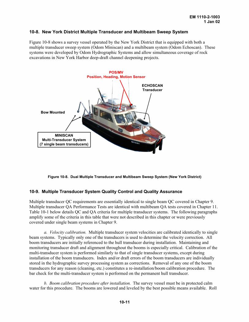
10-8. New York District Multiple Transducer and Multibeam Sweep System Figure 10-8 shows a survey vessel operated by the New York District that is equipped with both a multiple transducer sweep system (Odom Miniscan) and a multibeam system (Odom Echoscan). These systems were developed by Odom Hydrographic Systems and allow simultaneous coverage of rock excavations in New York Harbor deep-draft channel deepening projects.
Bow Mounted
ECHOSCANTransducer
MINISCANMulti-Transducer System
(7 single beam transducers)
POS/MVPosition, Heading, Motion Sensor
Figure 10-8. Dual Multiple Transducer and Multibeam Sweep System (New York District)
10-9. Multiple Transducer System Quality Control and Quality Assurance Multiple transducer QC requirements are essentially identical to single beam QC covered in Chapter 9. Multiple transducer QA Performance Tests are identical with multibeam QA tests covered in Chapter 11. Table 10-1 below details QC and QA criteria for multiple transducer systems. The following paragraphs amplify some of the criteria in this table that were not described in this chapter or were previously covered under single beam systems in Chapter 9. a. Velocity calibration. Multiple transducer system velocities are calibrated identically to single beam systems. Typically only one of the transducers is used to determine the velocity correction. All boom transducers are initially referenced to the hull transducer during installation. Maintaining and monitoring transducer draft and alignment throughout the booms is especially critical. Calibration of the multi-transducer system is performed similarly to that of single transducer systems, except during installation of the boom transducers. Index and/or draft errors of the boom transducers are individually stored in the hydrographic survey processing system as corrections. Removal of any one of the boom transducers for any reason (cleaning, etc.) constitutes a re-installation/boom calibration procedure. The bar check for the multi-transducer system is performed on the permanent hull transducer.
b. Boom calibration procedure after installation. The survey vessel must be in protected calm water for this procedure. The booms are lowered and leveled by the best possible means available. Roll
10-11

EM 1110-2-1003 1 Jan 02 motion must not be allowed at this time. A bar check using any of the accepted USACE methods is performed on the hull transducer. This will minimize the index and draft errors and establish the same speed of sound for all transducers. Next the bar is moved outward from the hull transducer (preferably by two steady small boats) to the nearest boom transducer on one side of the survey vessel. The hull transducer soundings are compared to the sounding values recorded at the hull transducer. Any discrepancy found is recorded as a combination of draft and index error. The opposite (negative) of this recorded value will be applied to all soundings from this particular transducer until the transducer is physically moved from the fixed position in the boom. All boom transducers are compared to the hull transducer by the same procedure. The area selected for the boom calibration should be where no changes in temperature or salinity could change the speed of sound during this important calibration. Clearly noticeable particles in the water column may also affect the speed of sound.
c. Periodic calibration of Ross Dolphin Sweep System (Philadelphia District Method). Periodic calibration of Ross Dolphin sweep systems is performed using basically the same criteria required for a single transducer system. Once a month, all transducers in the hull are calibrated, utilizing a standard bar lowered to the project depth directly under the vessel. Transducers in the port/starboard beams are calibrated on an annual basis. On a daily basis, a Ross ball check device, which is mounted as part of the referenced transducer pod, is utilized to obtain the speed of sound utilizing a 3½-deg transducer. The 3½-deg transducer is used to assure that the depth reference is as close to a true vertical distance as possible. A sound velocity profiler is also used daily to verify the ball check calibration procedure. Maintaining and monitoring the transducer draft is especially critical. Each transducer channel in the sweep is adjusted similar to the procedure used in the single transducer systems.
d. Lock chamber calibration. When a lock chamber with a clean, smooth floor is located in the district, multiple transducer sweep systems may be simultaneously calibrated. Calibration can be performed at varied surface elevations by drawing down the lock to desired intervals. The lock chamber affords a stable water surface that eliminates sea state effects on outer boom transducers. Individual transducer channels are calibrated and adjusted to read true depths.
e. Motion compensation requirements. Boom sweep systems are normally used on shallow draft
inland projects where sea state conditions are typically calm. Thus, full X-Y-Z inertial motion sensors are rarely added to these sweep systems unless sea states cause excessive errors. Roll correction is especially needed to correct for motion at the outer transducers. Physical movement of the outer transducers will determine whether surveys should continue under adverse sea conditions. Small roll errors can significantly affect depth readings on long boom systems--e.g., a 1-deg roll on a 25-ft boom causes approximately a 0.4 ft error in the sounding. Excessive heave should not be a problem on inland navigation projects where sweep systems are deployed.
(1) Roll compensation. Roll should be compensated for and corrected in the processing software
if the outer transducer on a boom experiences movement in excess that shown in Table 10-1. Smaller boat systems with short outriggers would be less subject to roll errors, so compensation would not be required. Beam steering position and slope corrections due to excessive roll and pitch are usually negligible for shallow-draft projects when wide beam transducers are used; thus the need for these corrections would be minimal.
(2) Yaw correction. Boom alignment due to vessel yaw is controlled using a flux gate compass, a
gyrocompass, or DGPS azimuth techniques. Software must correct each transducer offset relative to the positioning antenna in addition to correcting eccentricities due to yaw. This is done using similar techniques covered under the chapter on multibeam systems. Full yaw correction is critical.
(3) Heave correction. Only required in excessive sea states. (4) Pitch bias. Usually negligible given slow sweep speeds.
10-12

EM 1110-2-1003 1 Jan 02
(5) Latency. Latency between the positioning system and the multiple transducers is calibrated similar to single- or multibeam systems--see Chapters 9 and 11.
(6) Fixed offsets. Horizontal offsets of individual transducers are measured relative to the vessel
center of mass--the point where a HPR unit should be located. Vertical offsets (draft) are relative to the water line and are determined from a bar check. Parameters for multiple transducer systems are entered in processing software in a variety of methods--Figure 10-9 depicts a typical HYPACK MAX/HYSWEEP offset table.
Figure 10-9. Multiple transducer offsets (Coastal Oceanographics, Inc.)
f. Squat tests. At slow sweep speeds vessel squat and settlement should be minimal; however
this should be annually verified by a standard squat test as described in Chapter 9. g. Vessel speed and shoal/strike detection hits. Vessel speed should be controlled such that
objects or shoals above project grade receive at least three solid acoustic hits during a pass, or accumulate on overlapping passes. The depth update rate for each transducer channel must also be factored into the maximum speed determination. Data gaps can result if too high a velocity is maintained and individual channels do not update at a rapid enough level. Depths should be recorded at the maximum rate possible with the recording and processing system.
h. Quality assurance performance tests. QA tests with multiple transducer systems are
performed similar to multibeam systems, i.e., comparisons between two independently collected full data sets over the same area. Follow the QA performance procedures described in Chapter 11.
i. Recorded depths. For dredge payment surveys, the maximum update rate shall be used in
recording depths from each transducer channel. If depths are binned or gridded for plotting purposes, the shot depth nearest the bin centroid shall be used. Shoal biased (i.e., minimum) or average depths shall not be used to evaluate dredging progress. Data thinning shall be kept to a minimum for payment surveys. Likewise, bin sizes should be kept as small as possible. Refer to Chapter 11 (paragraph 11-12) for additional standards and guidance on intelligent data thinning and bin size restrictions.
10-13

EM 1110-2-1003 1 Jan 02
j. Archived data. It is not practical to retain hard copy records of multiple transducer surveys.
Original depth records from each transducer may be retained in digital format. Where contracted construction payment is involved, then a write-once type of media should be used.
T able 10-1. Quality Control and Quality Assurance Criteria for Multiple Transducer Surveys
PROJECT CLASSIFICATION Navigation & Dredging Support Surveys Other General Surveys & Studies
Bottom Material Classification (Recommended Standards) Hard Soft ACOUSTIC FREQUENCY (+ 10%) 200 kHz 200 kHz 200 kHz Beam angle @ - 3dB power points 8 deg 8-25 deg 8-25 deg Low frequency fluff applications 24-28 kHz 24-28 kHz 24-28 kHz VELOCITY CALIBRATION PROCEDURES: Perform at least 2/day 2/day 1/day Bar check Preferred Preferred Optional Ross Ball check (w/ periodic bar cks) Optional Optional Optional Check with bar every Month Month Month Velocity casts (w/ periodic bar checks) Optional Optional Optional Check with bar every Month Month Month Lead line calibrations allowed No No Optional BAR/BALL CHECK CALIBRATION: Bar/ball cables marked at least every 5 ft 5 ft 5 ft Independently measure cables Quarterly Annually Annually Correct line errors exceeding 0.05 ft 0.05 ft 0.05 ft Location of calibration At project site Near project site Vicinity Number of comparisons within range 3 + (every 5 ft) 2 2 Record calibrations to nearest 0.1 ft 0.1 ft 0.1 ft Data rejection tolerance between checks 0.2 ft 0.3 ft 0.5 ft VELOCITY PROBE CALIBRATIONS Perform internal calibration Weekly Weekly Monthly Record velocity to nearest 1 fps 1 fps 1 fps Record velocities at least every 5 ft 5 ft 5 ft Reject tolerance between checks 5 fps 5 fps 5 fps Location of calibration At project site Near project site Vicinity MOTION COMPENSATION REQUIREMENTS: Compensation reqd if roll-pitch exceeds > 1 deg > 2 deg No limit Compensation reqd if heave exceeds > 0.2 ft > 0.5 ft No limit Roll-Pitch beam steering position
displacement reqd if corr'n > 1 m Required Recommended Optional Roll-Pitch beam slope-vertical corr'n
reqd if error > 0.2 ft Required Recommended Optional Yaw position correction Required Required Not reqd Pitch bias test at installation at installation Not reqd
10-14
EM 1110-2-1003 1 Jan 02
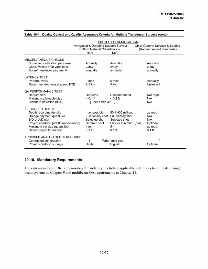
T able 10-1. Quality Control and Quality Assurance Criteria for Multiple Transducer Surveys (cont.)
PROJECT CLASSIFICATION Navigation & Dredging Support Surveys Other General Surveys & Studies
Bottom Material Classification (Recommended Standards) Hard Soft MISCELLANEOUS CHECKS Squat test calibration performed Annually Annually Annually Check vessel draft variations 2/day 2/day 2/day Boom/transducer alignments annually annually annually LATENCY TEST Perform every 3 mos 6 mos Annually Recommended vessel speed NTE 2-5 kts 5 kts Unlimited QA PERFORMANCE TEST Requirement Required Recommended Not reqd Maximum allowable bias < 0.1 ft < 0.2 ft N/A Standard deviation (95%) [ per Table 3-1 ] N/A RECORDED DEPTH Depth recording density max possible 50-1,000 millisec as reqd Dredge payment quantities Full density shot Full density shot N/A B/D or A/D plot Selected shot Selected shot N/A Project condition plot (thinned/binned) Centroid shot Shot or minimum (bias) Optional Maximum bin size (quantities) 1 m 5 m as reqd Record depth to nearest 0.1 ft 0.1 ft 0.1 ft ARCHIVED ANALOG DEPTH RECORDS Contracted construction [ Write-once disc ] Project condition surveys Digital Digital Optional
10-10. Mandatory Requirements The criteria in Table 10-1 are considered mandatory, including applicable references to equivalent single beam systems in Chapter 9 and multibeam QA requirements in Chapter 11.
10-15