chapter 11 intro - ct nemo programnemo.uconn.edu/publications/ms4/swqm_design_guidancesmall.pdf ·...
TRANSCRIPT

2004 The Connecticut Stormwater Quality Manualv i
Chapter 11 Stormwater Treatment Practice Design Guidance
Primary Treatment Practices.............................................................................11-2
Secondary Treatment Practices........................................................................11-3
Primary (P) Treatment Practices
11-P1 Stormwater Ponds................................................................11-P1-1
11-P2 Stormwater Wetlands ..........................................................11-P2-1
11-P3 Infiltration Practices .............................................................11-P3-1
11-P4 Filtering Practices..................................................................11-P4-1
11-P5 Water Quality Swales..........................................................11-P5-1
Secondary (S) Treatment Practices
Conventional Practices
11-S1 Dry Detention Pond ............................................................11-S1-1
11-S2 Underground Detention Facilities ...................................11-S2-1
11-S3 Deep Sump Catch Basins ...................................................11-S3-1
11-S4 Oil/Particle Separators .......................................................11-S4-1
11-S5 Dry Wells ...............................................................................11-S5-1
11-S6 Permeable Pavement ............................................................11-S6-1
11-S7 Vegetated Filter Strips/Level Spreaders ...........................11-S7-1
11-S8 Grass Drainage Channels ..................................................11-S8-1
Innovative/Emerging Technologies
11-S9 Catch Basin Inserts...............................................................11-S9-1
11-S10 Hydrodynamic Separators.................................................11-S10-1
11-S11 Media Filters .........................................................................11-S11-1
11-S12 Underground Infiltration Systems ...................................11-S12-1
11-S13 Alum Injection......................................................................11-S13-1

Chapter 11Stormwater Treatment
Practice Design Guidance

Chapter 11 Stormwater Treatment Practice Design Guidance
Primary Treatment Practices ............................................................................11-2
Secondary Treatment Practices .......................................................................11-3
Primary (P) Treatment Practices
11-P1 Stormwater Ponds ..............................................................11-P1-1
11-P2 Stormwater Wetlands.........................................................11-P2-1
11-P3 Infiltration Practices............................................................11-P3-1
11-P4 Filtering Practices ................................................................11-P4-1
11-P5 Water Quality ......................................................................11-P5-1
Secondary (S) Treatment Practices
Conventional Practices
11-S1 Dry Detention Pond...........................................................11-S1-1
11-S2 Underground Detention Facilities ..................................11-S2-1
11-S3 Deep Sump Catch Basins .................................................11-S3-1
11-S4 Oil/Particle Separators ......................................................11-S4-1
11-S5 Dry Wells .............................................................................11-S5-1
11-S6 Permeable Pavement...........................................................11-S6-1
11-S7 Vegetated Filter Strips/Level Spreaders..........................11-S7-1
11-S8 Grass Drainage Channels .................................................11-S8-1
Innovative/Emerging Technologies
11-S9 Catch Basin Inserts .............................................................11-S9-1
11-S10 Hydrodynamic Separators...............................................11-S10-1
11-S11 Media Filters .......................................................................11-S11-1
11-S12 Underground Infiltration Systems .................................11-S12-1
11-S13 Alum Injection....................................................................11-S13-1
Volume II: Design
2004 Connecticut Stormwater Quality Manual 11-1

2004 Connecticut Stormwater Quality Manual11-2
This chapter provides guidance on the design, construction, and maintenance of the stormwater treatment prac-tices contained in this Manual. Table 11-1 lists the individual primary and secondary stormwater treatmentpractices that were introduced in Chapter Six and are described further in subsequent sections of this chapter.
Primary Treatment PracticesThis chapter provides the following information foreach primary treatment practice:
Description: A brief description of the treatmentpractice. The stormwater management benefits of thetreatment practice (i.e., runoff volume reduction, pol-lutant reduction, stream channel/conveyanceprotection, and flood control) and effectiveness forremoval of specific categories of pollutants are sum-marized at the beginning of each description for quickreference and screening.
Design Variations: Descriptions of common designvariations for those treatment practices for which mul-tiple designs have been developed.
Advantages: The major beneficial factors or consid-erations (e.g., environmental, economic, safety) forselecting a specific stormwater treatment practice.
Limitations: The major limitations or drawbacks of astormwater treatment practice that may preclude itsuse for a given site.
Siting Considerations: The site conditions requiredfor implementation of a stormwater treatment prac-tice, such as minimum contributing drainage area,subsurface conditions, and minimum setbacks.
Design Criteria: Specific technical requirements andrecommendations for designing the major elements ofa stormwater treatment practice, including criteria fordesign variants within each treatment practice category.
Construction: Recommended construction proce-dures and methods to ensure that a stormwatertreatment practice functions as designed.
Inspection and Maintenance: Routine and non-rou-tine operation and maintenance required for thestormwater treatment practice to function properlyover time.
Table 11-1Summary of Stormwater Treatment Practices
Primary (P) Treatment Practice
Stormwater Ponds (P1)❍ Micropool Extended Detention Pond❍ Wet Pond❍ Wet Extended Detention Pond❍ Multiple Pond System❍ Pocket Pond
Stormwater Wetlands (P2)❍ Shallow Wetland❍ Extended Detention Wetland❍ Pond/Wetland System
Infiltration Practices (P3)❍ Infiltration Trench❍ Infiltration Basin
Filtering Practices (P4)❍ Surface Sand Filter❍ Underground Sand Filter❍ Perimeter Sand Filter❍ Organic Filter❍ Bioretention
Water Quality Swales (P5)❍ Dry Swale❍ Wet Swale
Secondary (S) Treatment Practice
Conventional Practices❍ Dry Detention Pond (S1)❍ Underground Detention Facilities (S2)❍ Deep Sump Catch Basins (S3)❍ Oil/Particle Separators (S4)❍ Dry Wells (S5)❍ Permeable Pavement (S6)❍ Vegetated Filter Strips/Level Spreaders (S7)❍ Grass Drainage Channels (S8)
Innovative/Emerging Technologies❍ Catch Basin Inserts (S9)❍ Hydrodynamic Separators (S10)❍ Media Filters (S11)❍ Underground Infiltration Systems (S12)❍ Alum Injection (S13)

2004 Connecticut Stormwater Quality Manual 11-3
Cost Considerations: Approximate capital costs todesign, construct, and implement the stormwatertreatment practice, as well as approximate annualoperation and maintenance costs, where available.
Secondary Treatment PracticesSecondary treatment practices are described in lessdetail due to their limited applicability for water qual-ity control. The following guidance is provided forthese treatment practices:
Description: A brief description and associatedstormwater management benefits of the treatmentpractice.
Reasons for Limited Use: Rationale for why thepractice generally does not meet the performancestandards required for classification as a primary treat-ment practice.
Suitable Applications: The conditions or applica-tions for which the practice is typically suitable (i.e.,pretreatment, ultra-urban environments, etc.)
Design Considerations: Key factors for siting,designing, and implementing the treatment practice.

2004 Connecticut Stormwater Quality Manual 11-PI-1
Stormwater Ponds
DescriptionStormwater ponds are vegetated ponds that retain a permanent pool ofwater and are constructed to provide both treatment and attenuation ofstormwater flows. This section addresses four types of stormwater ponds:
❍ Wet Pond
❍ Micropool Extended Detention Pond
❍ Wet Extended Detention Pond
❍ Multiple Pond System
Through careful design, stormwater ponds can be effective at removingurban pollutants. Treatment is primarily achieved by the sedimentationprocess where suspended particles and pollutants settle to the bottom of thepond. Stormwater ponds can also potentially reduce soluble pollutants instormwater discharges by adsorption to sediment, bacterial decomposition,and the biological processes of aquatic and fringe wetland vegetation.
The key to maximizing the pollutant removal effectiveness ofstormwater ponds is maintaining a permanent pool. To achieve this, wetponds typically require a large contributing watershed with either animpermeable liner or an elevated water table without a liner. The pool typ-ically operates on the instantaneously mixed reservoir principle whereincoming water mixes with the existing pool and undergoes treatmentthrough sedimentation and the other processes. When the existing pool isat or near the pond outlet or when the primary flow path through the pondis highly linear, the pond may act as a plug flow system in which incom-ing water displaces the permanent pool, which is then discharged from the pond. The value provided by this process is that a portion of the “new,” polluted runoff is retained as the “old,” treated water is dischargedfrom the pond, thereby allowing extended treatment of the water qualityvolume (WQV). For example, when sized to store the WQV, a pond system will retain all of the water from storms that generate runoff less thanor equal to the WQV and result in a significantly increased period of timeavailable for treatment. For storms that generate runoff greater than the WQV, wet ponds still provide a reduced level of treatment through
Treatment Practice Type
Primary Treatment Practice �
Secondary Treatment Practice
Stormwater ManagementBenefitsPollutant Reduction
Sediment �
Phosphorus �
Nitrogen �
Metals �
Pathogens �
Floatables* �
Oil and Grease* �
Dissolved Pollutants �
Runoff Volume ReductionRunoff Capture �
Groundwater Recharge �
Stream Channel Protection �
Peak Flow Control �
Key: � Significant Benefit� Partial Benefit� Low or Unknown
Benefit
*Only if a skimmer is incorporated
Implementation Requirements
Cost ........................................ModerateMaintenance.........................Moderate
Source: Nonpoint Education for Municipal Officials (NEMO).

2004 Connecticut Stormwater Quality Manual11-PI-2
conventional settling and filtration for the additionalrunoff volume that is conveyed through the pond.The pond volume should be greater than or equal tothe WQV to ensure at least one-day retention timewithin the pond.
When properly designed, the permanent poolreduces the velocity of incoming water to preventresuspension of particles and promote settling ofnewly introduced suspended solids. The energy dissi-pating and treatment properties of the permanentpool are enhanced by aquatic vegetation, which is anessential part of the stormwater pond design. In con-trast, dry detention ponds, or dry extended detentionponds that have no permanent pool, are not consid-ered an acceptable option for treating the WQV dueto the potential for resuspension of accumulated sed-iment by incoming storm flows during the earlyportion of a storm event when the pond is empty.
Several design variations of stormwater pondsexist that can fit a wide range of design conditions.Descriptions of these design variations are providedin the following section.
Design VariationsWet Ponds: Wet ponds typically consist of two gen-eral components - a forebay and a permanent wetpool. The forebay provides pretreatment by captur-ing coarse sediment particles in order to minimizethe need to remove the sediments from the primarywet pool. The wet pool serves as the primary treat-ment mechanism and where much of the retentioncapacity exists. Wet ponds can be sized for a widerange of watershed sizes, if adequate space exists.For example, a variation on the conventional wetpond, sometimes referred to as a “pocket pond”, isintended to serve relatively small drainage areas(between one and five acres). Because of thesesmaller drainage areas and the resulting lowerhydraulic loads of pocket ponds, outlet structurescan be simplified and often do not have safety fea-tures such as emergency spillways and low leveldrains. Figure 11-P1-1 depicts a typical schematicdesign of a conventional wet pond, while Figure11-P1-2 shows a typical schematic design of a mod-ified wet pond or “pocket pond”.
Several adaptations of this basic design havebeen developed to achieve the specific treatmentgoals of various watershed or site conditions. Thesewet pond design variations are described below.
Micropool Extended Detention Pond: Micropoolextended detention basins are primarily used for peakrunoff control and utilize a smaller permanent poolthan conventional wet ponds. While micropoolextended detention ponds are not as efficient as wetponds for the removal of pollutants, they should be
considered when a large open pool might be unde-sirable or unacceptable. Undesirable conditions couldinclude thermal impacts to receiving streams from alarge open pool, safety concerns in residential areas,or where maintaining a large open pool of waterwould be difficult due to a limited drainage area ordeep groundwater.
Micropool extended detention ponds are alsoefficient as a stormwater retrofit to improve the treat-ment performance of existing detention basins.Figure 11-P1-3 depicts a typical schematic design ofa micropool extended detention pond.
Wet Extended Detention Ponds: These ponds arevery similar to wet ponds with the exception that theirdesign is more focused on attenuating peak runoffflows. As a result, more storage volume is committedto managing peak flows as opposed to maximizingthe wet pool depth. The configuration of the outfallstructure may also differ from typical wet ponddesigns to provide additional storage volume abovethe level of the permanent pool. Figure 11-P1-4depicts a typical schematic design of a wet extendeddetention pond.
Multiple Pond System: Multiple pond systems con-sist of several wet pools that are constructed in aseries following a forebay. The advantage of thesesystems is that they can improve treatment efficiencyby better simulating plug flow conditions as com-pared to a single large wet pool. Also, these systemscan reduce overall maintenance needs since more fre-quent maintenance would be performed within thefirst pool cells as opposed to the large, primary pool.The disadvantage of these systems is that they typi-cally require more land area to treat the same waterquality volume. Figure 11-P1-5 depicts a typicalschematic design of a multiple pond system.
Advantages❍ Can capture/treat both particulate and soluble
pollutants. Stormwater ponds are one of the mosteffective stormwater treatment practices for treat-ing soluble pollutants.
❍ Can provide an aesthetic benefit if open water isdesired as part of an overall landscaping plan.
❍ May provide wildlife habitat with appropriatedesign elements.
❍ Can be adapted to fit a wide range of sites.Design variations allow this control to be uti-lized for both small and large drainage areas.Pollutant removal mechanisms make stormwaterponds efficient in treatment of pollutants-of-concern from a wide range of land uses.

2004 Connecticut Stormwater Quality Manual 11-PI-3
Figure 11-P1-1 Wet Pond
Source: Adapted from NYDEC, 2001.
Pond Buffer(10 to 50 feet)
Hardened Pad
Overflow Spillway
MaintenanceAccess Road
Native Landscaping Around Pool
Aquatic Bench
Safety Bench
Riser in Embankment
Riser/Barrel
Outfall
Emergency Spillway
Irregular Pool Shape6 to 8 Feet Deep
Forebay
Plan View
Section
Embankment
Riser
Emergency Spillway
StableOutfall
Anti-Seep Collar or Filter Diaphragm
BarrelReverse Pipe
Pond Drain
Extreme Flood Control
Overbank Flood Control
Channel ProtectionSafety Bench
Water QualityWet Pond
AquaticBench
Forebay
Inflow
Inflow
Berm

2004 Connecticut Stormwater Quality Manual11-PI-4
Limitations❍ Unlined ponds that intercept groundwater
have potential to impact groundwater quality ifdissolved pollutants are present in the runoff.
❍ Lined ponds typically require a minimumdrainage area in order to maintain a perma-nent pool, which may become difficult duringextended dry periods.
❍ Require a relatively large land area that isdirectly proportional to the size of the areadraining to it.
❍ May cause thermal impacts to receiving watersand thereby are not recommended to dischargedirectly to cold water fish habitats.
❍ Require more storage volume (i.e., above perma-nent pool) to attenuate peak flows.
❍ Potential breeding habitat for mosquitoes, partic-ularly for smaller ponds with stagnant water orisolated pockets of standing water (rather thanlarge open water bodies). Circulating water inthe permanent pool may minimize this problem.This may be a more significant problem forlined basins.
❍ Pollutant removal efficiency can be affected incold climates due to ice formation on the perma-nent pool and longer particle settling timesassociated with higher density water during winter months. However, modifications to apond’s design can help maintain the primarypollutant removal mechanism of sedimentation.
❍ Ponds with steep side slopes and/or deep wetpools may present a safety issue to nearby pedestrians.
❍ Stormwater ponds can serve as decoy wetlands,intercepting breeding amphibians movingtoward vernal pools. If amphibians deposit theireggs in these artificial ponds/wetlands, theyrarely survive due to the sediment and pollutantloads, as well as fluctuations in water quality,quantity, and temperature.
Siting ConsiderationsDrainage Area: Stormwater ponds that utilize a linersystem should have a contributing drainage area thatis adequate to maintain minimum water levels.Typically, minimum contributing watersheds forunlined ponds are twenty-five acres for wet ponds,wet extended detention ponds, and multiple pondsystems; ten acres for micropool extended detentionponds; and one to five acres for pocket ponds.
Groundwater: Unlined basins must intersect thegroundwater table in order to maintain the desiredpermanent pool. In this case, the elevations of thebasin should be established such that the ground-water elevation is equal to the desired permanentpool elevation. Seasonal variations of groundwaterelevations should be considered, which can be verypronounced in low permeability soils.
Land Uses: Land uses will dictate potential pollu-tants-of-concern and potential safety risks. For thoseland uses where there is significant potential for solu-ble pollutants, especially those that are highlysusceptible to groundwater transport, the use of aliner is recommended. An impermeable liner may notbe required depending on risk of downstream con-tamination, but a low permeability liner constructedin till soils may be acceptable. With regard to poten-tial safety issues, adjacent residential land uses posethe greatest risks where mosquito breeding and waterhazards must be considered.
Baseflow: A small amount of baseflow is desirable tomaintain circulation and reduce the potential for lowdissolved oxygen levels during late summer. Thisbaseflow can be provided by groundwater infiltratinginto either the basin or the collection system abovethe pond.
Site Slopes: Steep on-site slopes may result in theneed for a large embankment to be constructed to pro-vide the desired storage volume, which could requirea dam construction permit from the Connecticut DEP.Steep slopes may also present design and construc-tion challenges, and significantly increase the cost ofearthwork.
Receiving Waters: The sensitivity of receiving watersshould be evaluated to determine whether the effectsof the warmer stormwater discharges from the wetpond could be detrimental to cold water fish or othersensitive aquatic species.
Flood Zones: Ponds should not be located in flood-ways, floodplains, or tidal lands, especially those thatrequire construction of an embankment. Floodwaterscould flush out stored pollutants or damage pondembankments.
Natural Wetlands/Vernal Pools: Natural wetlandsand vernal pool depressions should not be used,either temporarily or permanently, as a stormwaterpond or wetland. Stormwater ponds should belocated at least 750 feet from a vernal pool. Theyshould not be sited between vernal pools, or in areasthat are known primary amphibian overland migra-tion routes.

2004 Connecticut Stormwater Quality Manual
Design CriteriaPond designs may vary considerably due to site con-straints, local requirements, or the designer’spreferences. Design considerations for stormwaterponds are presented below and summarized in Table11-P1-1.
ForebayA sediment forebay is recommended for all wet pondsystems. The purpose of the forebay is to provide pre-treatment by settling out coarse sediment particles,which will enhance treatment performance, reducemaintenance, and increase the longevity of astormwater pond. A forebay is a separate cell withinthe pond formed by a barrier such as an earthenberm, concrete weir, or gabion baskets.
❍ The forebay should be sized to contain at least10 percent of the WQV and be of an adequatedepth to prevent resuspension of collected sedi-ments during the design storm, often being four
to six feet deep. The goal of the forebay is to atleast remove particles consistent with the size ofmedium sand. The forebay storage volume maybe used to fulfill the total WQV requirement ofthis system. The forebay must also include addi-tional sediment storage volume that may not beused for WQV calculations.
❍ The outlet from the forebay should be designedin a manner that prevents erosion of theembankment and primary pool. This outlet canbe configured in a number of ways including aculvert, weir, or spillway channel. The outletshould be designed to convey the same designflow proposed to enter the basin. The outlet invertmust be elevated in a manner such that 10 per-cent of the WQV can be stored below it inaddition to the required sediment volume.
❍ The forebay should have a minimum length towidth ratio of 2:1 and a preferred length towidth ratio of 3:1.
11-PI-5
Parameter Design Criteria
Setback requirements1
Preferred Shape
Side Slopes
Length to Width Ratio
Pretreatment Volume
Pond Volume
Drainage Area
Underlying Soils
Capacity
Depth
❍ 50 feet from on-site sewage disposal systems❍ 50 feet from private wells❍ 10 feet from a property line❍ 20 feet from any structure❍ 50 feet from any steep slope (greater than 15%)❍ 750 feet from a vernal pool
Curvilinear
3:1 maximum or flatter preferred
3:1 minimum along the flow path between the inlet and outlet; flow length is the length atmid-depth (avg. top width+avg. bottom width)/2
Forebays are highly recommended for wet ponds and sized to contain 10% of the WQV. Forsites with potential for higher pollutant loads (see Chapter Seven), 100% of the WQV mustreceive pretreatment.
Minimum pond volume, including pretreatment volume, should be equal to or exceed theWQV.
Minimum contributing drainage area is 25 acres for wet ponds, 10 acres for extended deten-tion basins, and 1-5 acres for pocket ponds.
Low permeability soils are best (NRCS Hydrologic Soil Group A and B soils require modifica-tions to maintain a permanent pool unless groundwater is intercepted).
The minimum ratio of pool volume to runoff volume must be greater than 2:1 and preferably4:1. A 4:1 ratio provides 85-90% sediment removal based on a residence time of two weeks.
❍ An average pool depth of 3 to 6 feet is recommended and varying depths in the pond arepreferred.
❍ The aquatic bench should be 12-18 inches deep.❍ Ponds should not be greater than 8 feet deep.
Table 11-P1-1 Design Criteria for Stormwater Ponds
1 Minimum requirements. State and local requirements supercede.

2004 Connecticut Stormwater Quality Manual11-PI-6
Figure 11-P1-2 Pocket Pond
Source: Adapted from NYDEC, 2001.
SubmergedEarth Berm
MaintenanceAccess Road
Safety Bench
Aquatic Bench
Micropool
Embankment
Outfall
Extreme Flood Control
Overbank Flood Control
Channel ProtectionWater Quality
Forebay
Inflow
Plan View
Section
Embankment
Weir WallOutlet Structure
Wet Pool
Forebay
Inflow
GroundWater Table
Weir WallOutlet Structure
Embankment
StableOutfall
Hooded LowFlow Orifice

❍ Direct access for appropriate maintenanceequipment should be provided to the forebayand may include a ramp to the bottom if equip-ment cannot reach all points within the forebayfrom the top. The forebay can be lined with aconcrete pad to allow easy removal of sedimentand to minimize the possibility of excavatingsubsurface soils or undercutting embankmentsduring routine maintenance.
❍ A fixed vertical sediment depth marker should beinstalled in the forebay to measure sedimentdeposition.
❍ A barrier, such as an earthen berm, gabions, or a concrete weir may be used to separate theforebay from the permanent pool. This barriershould be armored as necessary to prevent erosion of the embankment if it overtops. Thisarmoring could consist of materials such asriprap, pavers, or geosynthetics designed to resistslope erosion. If a channel is used to conveyflows from the forebay to the pond, the sideslopes of the channel must be armored as well.
❍ Additional pretreatment can be provided in theforebay by raising the embankment to providesome detention of incoming flows.
Wet Pool Stormwater pond design features primarily enhancethe removal of pollutants by increasing the residencetime of stormwater in the pond and providing habitatfor aquatic plants.
❍ Provide water quality treatment storage to cap-ture the computed WQV from the contributingdrainage area in the proposed forebay, perma-nent pool, extended detention area, and marsh.The division of storage between the permanentpool and extended detention is outlined inTable 11-P1-2.
❍ Water quality storage can be provided in multi-ple cells. Performance is enhanced whenmultiple treatment pathways are provided byusing multiple cells, longer flow paths, high surface area to volume ratios, complex microto-pography, and/or redundant treatment methods(combinations of pool, extended detention, andmarsh).
❍ The minimum pool size should be equal to theWQV. A larger volume should be used to achievegreater pollutant removal when it is necessary tomeet specific water quality standards.
❍ Underwater or marsh berms may be incorporatedin the design to lengthen the flow path throughthe pond.
❍ Shade should be provided, at a minimum, atleast at the pond outlet in an effort to mitigatewarming of discharge water.
❍ The minimum length:width ratio for the pondis 3:1.
❍ Upper stages of the pond should provide tempo-rary storage of large storms (10, 25, or 100-yearevents) to control peak discharge rates.
❍ Provide variable pond depths of 4 to 6 feet butnot exceeding depths of 8 feet. Maintainingpond water depths in excess of 4 feet precludesinvasive emergent vegetation such as cattails.Emergent vegetation provides mosquito larvaewith refuge from predators and increases nutrient availability.
❍ Chemicals (e.g., aluminum sulfate or alum) can be injected into pond stormwater dischargesor added directly to the permanent pool or
Design VariationPercent of Water Quality Volume (WQV)
Permanent Pool Extended Detention
Wet Pond 100% 0%
Micropool Extended Detention Pond 20% min. 80% max.
Wet Extended Detention Pond 50% min. 50% max.
Multiple Pond System 50% min. 50% max.
Pocket Pond 50% min. 50% max.
Table 11-P1-2 Water Quality Volume Distribution in Pond Designs
Source: NYDEC, 2001.
2004 Connecticut Stormwater Quality Manual 11-PI-7

2004 Connecticut Stormwater Quality Manual11-PI-8
Figure 11-P1-3 Micropool Extended Dentention Pond
Source: Adapted from NYDEC, 2001.
ExistingVegetation Retained
Maximum Elevationof Safety Storm
Safety Bench
AquaticBench
Barrel
Outfall
Flood Control
Overbank Flood ControlChannel Protection
Water Quality
SedimentForebay
Inflow
Plan View
Section
Embankment
Micropool
Forebay
InflowStableOutfall
EmergencySpillway
Maintenance Access to Micropool
EmergencySpillway
Maximum Elevationof ED Pool
Hood
Rip-Rap Pilot Channel
Anti-Seep Collar orFilter Diaphragm

2004 Connecticut Stormwater Quality Manual 11-PI-9
sediment forebay to enhance removal of fineparticulates and dissolved pollutants within the pond.
❍ Maintain pond water quality sufficient to supportmosquito-feeding fish. Stormwater ponds oftendevelop mini-ecosystems where birds, frogs, andother insects feed, many of which are naturalpredators of mosquitoes and nuisance insects.Ponds can also be stocked with predatory fishnative to Connecticut that feed on mosquito larvae such as banded sunfish, flathead minnows,Eastern mud minnows, and several species ofkillfish. The DEP Fisheries Division should beconsulted regarding species selection. Other natural predators of mosquitoes such as dragon-fly nymphs can also be used.
Conveyance Stormwater should be conveyed to and from allstormwater management practices safely and to mini-mize erosion potential.
Inlet Protection❍ The number of inlets should be minimized and
one inlet is preferable. The inlet should belocated at the most hydraulically remote pointfrom the outlet to minimize the potential forshort-circuiting, and should be located in amanner that meets or exceeds desired length towidth ratios.
❍ Inlet areas should be stabilized to ensure thatnon-erosive conditions exist for the design storm event.
❍ The ideal inlet configuration is above the permanent pool to prevent potential hydraulicconstrictions due to freezing.
Outlet Protection
❍ The channel immediately below a pond outfallshould be modified to prevent erosion and con-form to natural topography by use of a plungepool or a riprap pad and sized for peak dis-charge velocities.
❍ Outlet protection should be used to reduce flowto non-erosive velocities from the principal spill-way based on actual cover and soil conditions.
❍ If a pond outlet discharges to a perennial streamor channel with dry weather base flow, treeclearing should be minimized and a forestedriparian zone re-established.
❍ To convey potential flood flows from the basin,an armored emergency spillway should be provided.
Pond Liners❍ When a pond is located such that the permanent
pool does not intercept groundwater, a liner maybe needed to maintain minimum water levels.Pond liners are also necessary for ponds thatmay present a risk to groundwater quality.Table 11-P1-3 lists recommended specificationsfor clay and geomembrane liners.
Pond Benches❍ For pond side slopes steeper than 4:1, provide a
flat safety bench that extends 10 feet outwardfrom the normal water edge to the toe of thepond side slope.
❍ Incorporate a flat aquatic bench that extends 10feet inward from the normal shoreline at a depthof 12-18 inches below the normal pool water sur-face elevation.
Linear Material Property Recommended Specifications
Clay Minimum Thickness 6 to 12 inches
Permeability 1x10⁻⁵ cm/sec1
Particle Size Minimum 15% passing #200 sieve1
Geomembrane Minimum Thickness 30 mils (0.03 inches)
Material Ultraviolet resistant, impermeable poly-liner
Table 11-P1-3 Linear Specifications
Source: 1NYDEC, 2001; all other listed specifications from City of Austin in Washington, 2000 (in Metropolitan Council, 2001).

2004 Connecticut Stormwater Quality Manual11-PI-10
Maintenance Reduction FeaturesIn addition to regular maintenance activities needed tomaintain the function of stormwater practices, somedesign features can be incorporated to ease the main-tenance burden of each practice. In wet ponds,maintenance reduction features include techniques to reduce the amount of maintenance needed, as wellas techniques to make regular maintenance activitieseasier.
❍ Ponds should be designed with non-clogging out-lets, such as a weir, or by incorporating trashracks for culverts and orifice openings.
❍ To prevent clogging from ice or floatables, areverse slope outlet pipe can be used to drawwater from below the permanent pool up to theoutlet structure. The invert of the pipe drawingfrom the pool should be at least 18 inches fromthe bottom to prevent sediment discharge.
❍ No orifice should be less than 6 inches in diameter with a trash rack to prevent clogging.
❍ Ponds should have a manually operated drain to draw down the pond for infrequent mainte-nance or dredging of the main cell of the pond.
❍ Metal components of outlet structures should becorrosion resistant, but not galvanized due to the contribution of zinc to water.
❍ Outlet structures should be resistant to frostheave and ice action in the pond.
Landscaping Constructing landscaped wet ponds can enhance theiraesthetic value. Aquatic plantings around the edge ofthe pond can provide pollutant uptake, stabilize thesoil at the edge of the pond, and improve habitat.Maintaining high vegetation along the edge of thepond (not mowing to the edge) can also deter water-fowl access and filter pollutants.
❍ Wetland plantings should be encouraged in apond design, either along the aquatic bench(fringe wetlands), the safety bench and sideslopes, or within shallow areas of the pool.
❍ The best depth for establishing wetland plants,either through transplantation or volunteer colo-nization, is within approximately six inches ofthe normal pool elevation.
❍ Soils should be modified (e.g., scarified or tilled)to mitigate compaction that occurs during con-struction around the proposed planting sites.
❍ Avoid species that require full shade, are suscep-tible to winterkill, or are prone to wind damage.
❍ Woody vegetation may not be planted or allowedto grow within 25 feet of the toe of the embank-ment and 25 feet from the principal spillwaystructure.
❍ Existing trees should be preserved in the bufferarea during construction. It is desirable to locateforest conservation areas adjacent to ponds. Tohelp discourage resident geese populations, the buffer can be planted with trees, shrubs, andnative ground covers.
❍ Annual mowing of the pond buffer is onlyrequired along maintenance rights-of-way andthe embankment. The remaining buffer can bemanaged as a meadow (mowing every otheryear) or forest.
❍ Plant the pond with salt-tolerant vegetation if thestormwater pond receives road runoff.
Cold Climate Pond Design ConsiderationsThe following design elements should be consideredto minimize potential performance impacts caused bycold weather:
❍ Inlet pipes should not be submerged, since thiscan result in freezing and upstream damage orflooding.
❍ Bury all pipes below the frost line to prevent frostheave and pipe freezing. Bury pipes at the pointfurthest from the pond deeper than the frost lineto minimize the length of pipe exposed.
❍ Increase the slope of inlet pipes to a minimum of1 percent, if site conditions allow, to preventstanding water in the pipe and reduce the poten-tial for ice formation.
❍ If perforated riser pipes are used, the minimumorifice diameter should be 0.5 inches. In addi-tion, the pipe should have a diameter of at least6 inches.
❍ When a standard weir is used, the minimum slotwidth should be 3 inches, especially when the slotis tall.
❍ Baffle weirs can prevent ice formation near theoutlet by preventing surface ice from blockingthe inlet, encouraging the movement of base flowthrough the system.
❍ In cold climates, riser hoods and reverse slopepipes should draw from at least 6 inches belowthe typical ice layer. This design encourages cir-culation in the pond, preventing stratificationand formation of ice at the outlet. Reverse slopepipes should not be used for off-line ponds.

11-PI-11
Figure 11-P1-4 Wet Extended Detention Pond
Source: Adapted from NYDEC, 2001.
Permanent Pool6 to 8 Feet Deep
PreserveRiparianCanopy
Barrel
Outfall
Flood Control
Overbank Flood Control
Channel ProtectionWater Quality
ForebayInflow
Plan View
Section
Embankment
Reverse Pipe
Forebay
InflowStableOutfall
EmergencySpillway
EmergencySpillway
Maximum ExtendedDetention Limit
Riser
Overflow Spillway
Anti-Seep Collar orFilter Diaphragm
MaintenanceAccess Road Aquatic Bench
Safety Bench
Riser in Embankment
Riser/Barrel
Maximum Safety Storm Limit
Berm
Pond Buffer(10 to 50 Feet
Pond Drain
Wet Pool
AquaticBench
2004 Connecticut Stormwater Quality Manual

2004 Connecticut Stormwater Quality Manual
❍ Trash racks should be installed at a shallowangle to prevent ice formation.
❍ Additional storage should be provided to accountfor storage lost to ice buildup. Ice thickness maybe estimated by consulting with local authorities(e.g. the fire department) with knowledge of thetypical ice thickness in the area.
Construction❍ Any stormwater treatment practices that create
an embankment, including stormwater ponds,are under the jurisdiction of the Dam SafetySection of the Connecticut DEP Inland WaterResources Division (IWRD) and should be constructed, inspected, and maintained inaccordance with Connecticut General Statutes§§22a-401 through 22a-411, inclusive, andapplicable DEP guidance.
❍ Avoid soil compaction to promote growth of vegetation.
❍ Temporary erosion and sediment controls shouldbe used during construction and sedimentdeposited in the stormwater pond should beremoved after construction.
❍ Appropriate soil stabilization methods should beused before permanent vegetation is established.Seeding, sodding, and other temporary soil stabilization controls should be implemented inaccordance with the Connecticut Guidelines forSoil Erosion and Sediment Control.
❍ Temporary dewatering may be required if excavation extends below the water table.Appropriate sedimentation controls will berequired for any dewatering discharges.
Inspection and Maintenance❍ Plans for stormwater ponds should identify
detailed inspection and maintenance require-ments, inspection and maintenance schedules,and those parties responsible for maintenance.
❍ The principal spillway should be equipped with a removable trash rack, and generally accessiblefrom dry land.
❍ Sediment removal in the forebay should occur at a minimum of every five years or after thesediment storage capacity in the forebay capacity has been filled.
11-PI-12
Activity Schedule
❍ If wetland components are included, inspect for invasive vegetation.
❍ Inspect for damage.
❍ Note signs of hydrocarbon build-up, and remove if detected.
❍ Monitor for sediment accumulation in the facility and forebay.
❍ Examine to ensure that inlet and outlet devices are free of debris and operational.
❍ Repair undercut or eroded areas.
❍ Clean and remove debris from inlet and outlet structures.
❍ Mow side slopes. High grass along pond edge will discourage waterfowl from taking up residence andserve to filter pollutants.
❍ Wetland plant management and harvesting.
❍ Drain pond in fall and let frost kill plants, then dredge in spring.
❍ Removal of sediment from the forebay.
❍ Remove sediment when the pool volume has become reduced significantly, or when significant algalgrowth is observed.
Semi-annual inspection
Annual inspection
As needed maintenance
Monthly maintenance
Annual maintenance(if needed)
5 year maintenance
10 year maintenance; more frequent dredging in developingwatersheds with significant sediment loads
Table 11-P1-4 Typical Maintenance Activities for Stormwater Ponds
Source: Adapted from WMI, 1997.

2004 Connecticut Stormwater Quality Manual 11-PI-13
Figure 11-P1-5 Multiple Pond System
Source: Adapted from NYDEC, 2001.
Maintenance
Access Road
Safety Bench
AquaticBench
Riser
Outfall
Flood Control
Overbank Flood Control
Channel Protection
Inflow
Plan View
Section
Embankment
InflowStableOutfall
EmergencySpillway
EmergencySpillway
Anti-Seep Collar orFilter Diaphragm
Reverse PipePond Drain
Cell 3(Wet Pond)
WQV WQV
SafetyBench
Cell 2(Wet Pond)
Cell 1(Wet Pond) Barrel
WQV
Aquatic Bench
Overflow Spillway(Typical)
Cell 1(Forebay)
Maintenance Access Road
Cell 2
Cell 3 Riser/Barrel
SafetyBench

2004 Connecticut Stormwater Quality Manual11-PI-14
❍ Sediment removed from stormwater pondsshould be disposed of according to anapproved comprehensive operation andmaintenance plan.
❍ Recommended maintenance activities forstormwater ponds are summarized in Table 11-P1-4.
Maintenance Access❍ A maintenance right-of-way or easement should
extend to the pond from a public road.
❍ Maintenance access should be at least 12 feetwide, have a maximum slope of no more than15 percent, and be appropriately stabilized towithstand maintenance equipment and vehicles.
❍ The maintenance access should extend to theforebay, safety bench, riser, and outlet and bedesigned to allow vehicles to turn around.
Non-clogging Low Flow Orifice❍ A low flow orifice shall be provided, with the size
of the orifice sufficient to ensure that no cloggingwill occur.
❍ The low flow orifice should be adequately pro-tected from clogging by either an acceptableexternal trash rack (recommended minimumorifice of 6 inches) or by internal orifice protec-tion that may allow for smaller diameters(minimum of 1 inch).
❍ The preferred method is a submerged reverse-slope pipe that extends downward from the riserto an inflow point one foot below the normalpool elevation.
❍ Alternative methods are to employ a broadcrested rectangular, V-notch, or proportionalweir, protected by a half-round pipe that extendsat least 12 inches below the normal pool level.
❍ The use of horizontally extended perforated pipeprotected by geotextile fabric and gravel is notrecommended. Vertical pipes may be used as analternative if a permanent pool is present.
Riser in Embankment❍ The riser must be located within the embank-
ment for maintenance access, safety andaesthetics.
❍ Lockable manhole covers and manhole stepswithin easy reach of valves and other controlsshould provide access to the riser. The principalspillway opening should be “fenced” with pipe at8-inch intervals for safety purposes.
Pond Drain❍ Except where local slopes prohibit this design,
each pond should have a drain pipe that cancompletely or partially drain the pond. Thedrain pipe shall have an elbow or protectedintake within the pond to prevent sediment depo-sition in the pipe, and a diameter capable ofdraining the pond within 24 hours.
❍ Pond retention times can be increased toenhance water quality control during stormevents by maintaining ponds at low levels beforestorms and increasing the available pond volumeduring storms.
❍ Care should be exercised during pond drainingto prevent rapid drawdown and minimizedownstream discharge of sediments or anoxicwater. The approving jurisdiction should be notified before draining a pond.
Adjustable Gate Valve❍ Both the WQV extended detention pipe and the
pond drain may be equipped with an adjustablegate valve, typically a handwheel activated knifegate valve.
❍ Valves should be located inside of the riser at apoint where they will not normally be inundatedand can be operated in a safe manner.
❍ Both the WQV extended detention pipe and thepond drain should be sized one pipe size greaterthan the calculated design diameter.
❍ To prevent vandalism, the handwheel should bechained to a ringbolt, manhole step, or otherfixed object.

2004 Connecticut Stormwater Quality Manual
Safety Features❍ Side slopes to the pond should not exceed 3:1
and should terminate at a safety bench.
❍ The principal spillway opening must not permitaccess by small children, and endwalls abovepipe outfalls greater than 48 inches in diametermust be fenced to prevent a hazard.
❍ Both the safety bench and the aquatic benchmay be landscaped to prevent access to the pool.
❍ Warning signs prohibiting swimming and skatingshould be posted.
❍ Pond fencing is generally not encouraged, butmay be required by some municipalities. Thepreferred method is to grade the pond to elimi-nate dropoffs or other safety hazards.
Cost Considerations Wet ponds are relatively inexpensive stormwater prac-tices, but costs vary widely depending on thecomplexity of the design or difficulty of site con-straints. The costs of stormwater ponds may beestimated using the following equation (Brown andSchueler, 1997):
C = 24.5V 0.705
where: C = Construction, design, and permitting cost. V = Volume in the pond to include the
10-year storm (ft3).
Costs should be adjusted for inflation to reflect currentcosts. The annual cost of routine maintenance is typi-cally estimated at about 3 to 5 percent of theconstruction cost (EPA Wet Pond Fact Sheet,http://www.epa.gov/npdes/menuofbmps/menu.htm).Ponds typically have a design life longer than twentyyears.
ReferencesBrown, W. and Shueler, T. 1997. The Economics ofStormwater BMPs in the Mid-Atlantic Region. Centerfor Watershed Protection. Elliot City, MD.
Galli, F. 1990. Thermal Impacts Associated withUrbanization and Stormwater Best ManagementPractices. Metropolitan Washington Council ofGovernments. Prepared for: Maryland Department ofthe Environment. Baltimore, MD.
Metropolitan Council. 2001. Minnesota Urban SmallSites BMP Manual: Stormwater Best ManagementPractices for Cold Climates. Prepared by BarrEngineering Company. St. Paul, Minnesota.
New York State Department of EnvironmentalConservation (NYDEC). 2001. New York StateStormwater Management Design Manual. Preparedby Center for Watershed Protection. Albany, NewYork.
Oberts, G. 1994. Performance of Stormwater Pondsand Wetlands in Winter. Watershed ProtectionTechniques 1(2): 64-68.
Schueler, T. 1997. Influence of Groundwater onPerformance of Stormwater Ponds in Florida.Watershed Protection Techniques 2(4): 525-528.
United States[E1] Environmental Protection Agency(EPA). 2002. National Menu of Best ManagementPractices for Stormwater Phase II. URL:http://www.epa.gov/npdes/menuofbmps/menu.htm,Last Modified January 24, 2002.
Washington State Department of Ecology(Washington). 2000. Stormwater ManagementManual for Western Washington, Final Draft.Olympia, Washington.
Watershed Management Institute (WMI). 1997.Operation, Maintenance, and Management ofStormwater Management Systems. Prepared for U.S.Environmental Protection Agency. Office of Water.Washington, D.C.
11-PI-15

2004 Connecticut Stormwater Quality Manual 11-P2-1
Stormwater Wetlands
DescriptionStormwater wetlands are constructed wetlands that incorporate marshareas and permanent pools to provide enhanced treatment and attenuationof stormwater flows. Stormwater wetlands differ from stormwater ponds inthat wetland vegetation is a major element of the overall treatment mech-anism as opposed to a supplementary component. This section includesthree types of stormwater wetlands:
❍ Shallow Wetland
❍ Extended Detention Shallow Wetland
❍ Pond/Wetland System
While stormwater wetlands can provide some of the ecological benefitsassociated with natural wetlands, these benefits are secondary to the func-tion of the system to treat stormwater. Stormwater wetlands can be veryeffective at removing pollutants and reducing peak flows of runoff fromdeveloped areas. Removal of particulate pollutants in stormwater wetlandscan occur through a number of mechanisms similar to stormwater pondsincluding sedimentation and filtration by wetland vegetation. Soluble pollutants can also be removed by adsorption to sediments and vegetation,absorption, precipitation, microbial decomposition, and biologicalprocesses of aquatic and fringe wetland vegetation. Stormwater wetlandsare particularly advantageous when nitrogen and/or dissolved pollutantsare a concern.
The key to maximizing pollutant removal effectiveness in stormwater wetlands is maintaining wet conditions adequate to support wetland veg-etation. To achieve this, the constructed wetlands must either intercept thegroundwater table or must be lined with an impermeable liner and have awatershed large enough to supply storm flows that will maintain wetnesseven during dry periods.
Treatment Practice Type
Primary Treatment Practice �
Secondary Treatment Practice
Stormwater ManagementBenefitsPollutant Reduction
Sediment �
Phosphorus �
Nitrogen �
Metals �
Pathogens �
Floatables* �
Oil and Grease* �
Dissolved Pollutants �
Runoff Volume ReductionRunoff Capture �
Groundwater Recharge �
Stream Channel Protection �
Peak Flow Control �
Key: � Significant Benefit� Partial Benefit� Low or Unknown
Benefit
*Only if a skimmer is incorporated
Implementation Requirements
Cost ........................................ModerateMaintenance.........................Moderate
Source: Nonpoint Education for Municipal Officials (NEMO).

2004 Connecticut Stormwater Quality Manual11-P2-2
Stormwater wetland systems should be designed tooperate on the plug flow principle where incomingwater displaces the water retained in the system fromthe previous storm event. This is accomplished bymaximizing length versus width ratios and/or by creating distinct cells along the treatment path.Ideally, the wetland system would be designed toretain the water quality volume (WQV) betweenstorm events. As a result, storms that generate runoffless than the WQV would be entirely retained whileonly a percentage of the runoff from storms that gen-erate more than the WQV would be retained. Thevalue provided by this process is that a portion of the“new” polluted runoff is retained, and the “old”treated water is discharged from the wetland, therebyallowing extended treatment of the WQV.
Stormwater wetlands should be equipped with a sediment forebay or similar form of pretreatment tominimize the discharge of sediment to the primarytreatment wetland. High solids loadings to the systemwill degrade system performance and result in morefrequent cleaning, which could result in additionaldisturbance to the wetland vegetation. A micropool orpermanent pool is often included just prior to the discharge for additional solids removal.
Design VariationsThere are several common stormwater wetlanddesign variations. The various designs are character-ized by the volume of the wetland in the deep pool,high marsh, and low marsh zones, and whether thedesign allows for detention of small storms above thepermanent pool.
Shallow Wetland: Most shallow wetland systems,also referred to as shallow marsh wetlands, consist ofaquatic vegetation with a permanent pool rangingfrom 6 to 18 inches during normal conditions.Shallow wetlands are designed such that flow throughthe wetlands is conveyed uniformly across the treat-ment area. While pathways, streams or other variedwater depths could enhance the aesthetic or ecosys-tem value of the wetland, they could also causeshort-circuiting through the wetland thereby reducingthe overall treatment effectiveness. As a result, tomaximize treatment performance, providing a uni-formly sloped system is recommended. In order toenhance plug flow conditions across the wetland,individual wetland cells can be constructed and sepa-rated by weirs. Figure 11-P2-1 depicts a typicalschematic design of a shallow wetland.
Extended Detention Shallow Wetland: Extendeddetention shallow wetlands provide a greater degreeof downstream channel protection as they aredesigned with more vertical storage capacity. The
additional vertical storage volume also provides extrarunoff detention above the normal pool elevations.Water levels in the extended detention shallow wet-land may increase by as much as three feet after astorm event and return gradually to pre-storm eleva-tions within 24 hours of the storm event. The growingarea in extended detention shallow wetlands extendsfrom the normal pool elevation to the maximumwater surface elevation. Wetland plants that tolerateintermittent flooding and dry periods should beselected for the extended detention area above theshallow marsh elevations. Figure 11-P2-2 depicts atypical schematic design of an extended detentionshallow wetland.
Pond/Wetland Systems: Multiple cell systems, suchas pond/wetland systems, utilize at least one pondcomponent in conjunction with a shallow marshcomponent. The first cell is typically a wet pond,which provides pretreatment of the runoff by remov-ing particulate pollutants. The wet pond is also usedto reduce the velocity of the runoff entering the sys-tem. The shallow marsh then polishes the runoff,particularly for soluble pollutants, prior to discharge.These systems require less space than the shallowmarsh systems since more of the water volume isstored in the deep pool which can be designed toreduce peak flows. Because of this system’s ability tosignificantly reduce the velocity and volume ofincoming peak flows (i.e., flow equalization or damp-ening), it can often achieve higher pollutant removalrates than other similarly sized stormwater wetlandsystems. Figure 11-P2-3 depicts a typical schematicdesign of a pond/wetland system.
Advantages❍ Efficient at removing both particulate and solu-
ble pollutants.
❍ Capable of providing aesthetic benefits.
❍ Capable of providing wildlife habitat withappropriate design elements.
❍ Provide ability to attenuate peak runoff flows.
Limitations❍ More costly than extended detention basins.
❍ Require a relatively large land area that isdirectly proportional to the size of the contribut-ing drainage area.
❍ Very sensitive to the ability to maintain wet con-ditions especially during extended dry weatherwhen there may be significant evaporative losses.

2004 Connecticut Stormwater Quality Manual 11-P2-3
Figure 11-P2-1 Shallow Wetland
Source: Adapted from King County Department of Natural Resources, 1998.
first cell (forebay)
wetland celloutflow
access road
access road
inflow
spillway
inlet submerged
inlet erosion control/slope protection (2’ min.)
sediment storage depth = 1’ min.
Slope maybe 2:1 when top submerged 1ft below design WS
If required, place liner insecond cell to hold water
inlet
first cell depth4’ min. to 8’ max
outlet structure
18” typ.6”
2 min1
WQ design WS
plant with wetland plants
Plan View
Section

2004 Connecticut Stormwater Quality Manual11-P2-4
❍ May cause thermal impacts to receiving watersand thereby should not discharge directly to coldwater fish habitats.
❍ Potential breeding habitat for mosquitoes, particularly for systems with isolated pockets ofstanding water (standing longer than 5 days).Circulating water in the permanent pool mayminimize this problem. This may be a more significant problem for lined systems.
❍ Wetland systems with steep side slopes and/ordeep wet pools may present a safety issue tonearby pedestrians.
❍ Stormwater wetlands can serve as decoy wet-lands, intercepting breeding amphibians movingtoward vernal pools. If amphibians deposit theireggs in these artificial wetlands, they rarely sur-vive due to the sediment and pollutant loads, aswell as fluctuations in water quality, quantity,and temperature.
Siting ConsiderationsDrainage Area: Stormwater wetlands that utilize aliner system to maintain the desired permanent poolshould have a contributing drainage area that is adequate to maintain minimum water levels.Typically, minimum contributing drainage areas aretwenty-five acres, especially for shallow systems. Awater budget for the wetlands should be calculated toensure that evaporation losses do not exceed inflowsduring warm weather months.
Groundwater: Unlined basins must intersect thegroundwater table in order to maintain the desiredpermanent pool. In this case, the elevations of thebasin should be established such that the ground-water elevation is equal to the desired permanentpool elevation. Seasonal variations of groundwaterelevations should be considered, which can be verypronounced in low permeability soils.
Land Uses: Land uses will dictate potential pollutants-of-concern and potential safety risks. For those landuses where there is significant potential for solublepollutants, especially those that are highly susceptibleto groundwater transport, the use of a liner is recommended. An impermeable liner may not berequired, depending on the risk of downgradient con-tamination, but a low permeable liner constructed intill soils may be acceptable. Adjacent residential landuses pose the greatest public safety risks where mos-quito breeding and water hazards must be considered.
Baseflow: A small amount of baseflow is desirable tomaintain circulation and reduce the potential for lowdissolved oxygen levels during late summer, and toreduce mosquito breeding. This baseflow can be pro-vided by groundwater infiltrating into either thewetland or the collection system above the pond.
Site Slopes: Steep on-site slopes may result in theneed for a large embankment to be constructed toprovide the desired storage volume and could requirea dam construction permit from the Connecticut DEP. Steep slopes may also present design and construction challenges, and significantly increase thecost of earthwork.
Receiving Waters: The sensitivity of receiving watersshould be evaluated to determine whether the effectsof the warmer stormwater discharges from the wetland could be detrimental to cold-water fish orother sensitive aquatic species.
Flood Zones: Constructed wetlands should not belocated in floodways, floodplains, or tidal lands, espe-cially those that require construction of anembankment. Floodwaters could flush out stored pol-lutants or damage pond embankments.
Natural Wetlands/Vernal Pools: Natural wetlandsand vernal pool depressions should not be used,either temporarily or permanently, as a stormwaterpond or wetland. Stormwater wetlands should belocated at least 750 feet from a vernal pool. Theyshould not be sited between vernal pools or in areasthat are known primary amphibian overland migrationroutes.
Design CriteriaWetland designs may vary considerably due to siteconstraints, local requirements, or the designer’s pref-erences. The five common design elements thatshould be considered for all stormwater wetlands are:
❍ Pretreatment
❍ Treatment
❍ Conveyance
❍ Maintenance reduction
❍ Landscaping
Design considerations for stormwater wetlands arepresented below and summarized in Table 11-P2-1.

2004 Connecticut Stormwater Quality Manual 11-P2-5
Figure 11-P2-2 Extended Detention Shallow Wetland
Source: Adapted from NYDEC, 2001.
Maximum ED limit
Riser in embankment
Riser/Barrel
Outfall
Emergency spillway
Safety bench
Forebay
MicropoolInflow
Pond buffer (25 ft. minimum)
High marsh(Less than 6” water depth)
Low marsh(water depth between 6” and 18”)
Extreme flood control
Wetlands high marsh
Emergency spillway
Stable outfall
Barrel
Pond drainLow marshForebay
Inflow
Reverse pipe
Embankment
Riser
Overbank flood controlChannel protection
Water quality
Anti-seep collar or filter diaphragm
Permanentpool
Section
Plan View

2004 Connecticut Stormwater Quality Manual11-P2-6
ForebayA sediment forebay is recommended for all storm-water wetland systems. Sediment forebays providepretreatment by settling out coarse solids, whichenhances treatment performance, reduces mainte-nance, and increases the longevity of the system. Thisis especially critical in wetland systems where removalof solids would disturb existing wetland vegetationand temporarily affect treatment performance.
❍ The forebay should be sized to contain at least10 percent of the WQV and have an adequatedepth to prevent resuspension of collected sedi-ments during the design storm, often being 4 to 6 feet deep. Maintaining water depths inexcess of 4 feet precludes invasive emergent vegetation such as cattails. Emergent vegetationprovides mosquito larvae with refuge from predators and increases nutrient availability.
❍ In larger open water areas of the wetland system(forebay and micropool), maintain water qualitysufficient to support mosquito-feeding fish.Stormwater ponds and wetlands often developmini-ecosystems where birds, frogs, and otherinsects feed, many of which are natural preda-tors of mosquitoes and nuisance insects. Pondscan also be stocked with predatory fish native toConnecticut that feed on mosquito larvae such asbanded sunfish, flathead minnows, Eastern mudminnows, and several species of killfish. The DEPFisheries Division should be consulted regardingspecies selection. Other natural predators of mos-quitoes such as dragonfly nymphs can also beused.
❍ The forebay must also include additional sedi-ment storage volume that may not be used forWQV calculations.
1Minimum requirements. State and local requirements supercede.
Source: Adapted from MADEP, 1997 and Schueler, 1992.
Parameter Design Criteria
Setback requirements1
Preferred Shape
Side Slopes
Length to Width Ratio
Pretreatment Volume
Drainage Area
Underlying Soils
Size
Depth
❍ 50 feet from on-site sewage disposal system❍ 50 feet from private well❍ 10 feet from property line❍ 20 feet from any structure❍ 50 feet from any steep slope (greater than 15%)❍ 750 feet from a vernal pool
Curvilinear
3:1 maximum or flatter preferred
3:1 minimum along the flow path between the inlet and outlet; flow length is the length atmid-depth. Mid-depth is (avg. top width+avg. bottom width)/2
Forebays are highly recommended for stormwater wetlands and sized to contain at least 10%of the WQV. Outlet micropools should also be sized to contain 10% of the WQV. For siteswith potential for higher pollutant loads, 100% of the WQV must receive pretreatment.
Minimum contributing drainage area is typically 25 acres. Stormwater wetland should have asurface area at least 1 to 1.5% of the contributing watershed area.
Low permeability soils are best (NRCS Hydrologic Soil Group A and B soils require modifica-tions to maintain a permanent pool unless groundwater is intercepted).
The size of the wetland area will be based on desired pollutant removal efficiencies and thedepth of water available to store the WQV. Suggested guidelines for the ratio of wetland towatershed areas is 0.2 for shallow marshes and 0.01 for extended detention shallow wetlandsystems and pond/wetlands.
Average water levels in the marsh/wetland areas can vary between 0.5 and 1.5 feet. Maximumwater depths will depend on the site topography and the design of the system. Forebays andmicropools should typically have a permanent pool depth of between 4 and 6 feet.
Table 11-P2-1 Design Criteria for Stormwater Wetlands

2004 Connecticut Stormwater Quality Manual 11-P2-7
❍ The outlet from the forebay should be designedin a manner to evenly distribute flow across thewetland/marsh area and prevent erosion of theembankment. This outlet can be configured in anumber of ways, including a culvert with a dis-tribution header or spillway channel. The outletshould be designed to safely convey the samedesign flow that is proposed to enter the basin.The outlet invert must be elevated in a mannersuch that 10 percent of the WQV can be storedbelow it in addition to the required sediment volume.
❍ The forebay should have a minimum length to width ratio of 2:1 and a preferred length to width ratio of 3:1.
❍ Direct access for appropriate maintenanceequipment should be provided to the forebayand may include a ramp to the bottom if equip-ment cannot reach all points within the forebayfrom the top. The forebay can be lined with aconcrete pad to allow easier removal of sedimentand to minimize the possibility of excavatingsubsurface soils or undercutting embankmentsduring routine maintenance.
❍ A fixed vertical sediment depth marker should be installed in the forebay to measure sedimentdeposition.
❍ A barrier, such as an earthen berm, gabions, or a concrete weir may be used to separate theforebay from the permanent pool. This barriershould be armored as necessary to prevent erosion of the embankment if it overtops. Thisarmoring could consist of materials such asriprap, pavers, or geosynthetics designed to resist slope erosion.
❍ Additional pretreatment can be provided in theforebay by raising the embankment to providesome detention of incoming flows.
Wetland/Marsh Area The size of the wetland/marsh area should be basedon pollutant influent concentrations, base flow, peakdesign flow, and desired effluent concentrations.Kadlec and Knight (1996) have developed area-based,first-order wetland design models to predict treatmentarea requirements. The use of these models is recom-mended to size the wetland areas. This model is as follows:
J = k (C – C*) ; where k = k20 θk(T-20)
C* = C*20 θc(T-20)
Where: J = Removal rate (g/m2/yr)k = First-order, area-based rate constant (m/yr)k20 = Rate constant at 20°C (m/yr)C = Pollutant concentration (mg/L)C* = Irreducible background concentration (mg/L)C*20= Irreducible background concentration at 20°C (mg/L)T = Temperature, °Cθc = Temperature coefficient for background concentrationθk = Temperature coefficient for rate constant
Wetland Area (based on modified plug-flow hydraulics):
A = Q / HLR = -Q ⟨ ln (C2 - C*)⟩k C1 - C*
Where: HLR = Hydraulic loading rate (m/yr)A = Wetland area at normal pool elevation (m2), excluding habitat islandsQ = Design inflow rate (m3/yr)C1 = Inflow concentration (mg/L)C2 = Outflow concentration (mg/L)
General Model:

2004 Connecticut Stormwater Quality Manual11-P2-8
In order to better simulate plug flow conditions andminimize short-circuiting, individual wetland cells canbe constructed along the flow path. Weirs, berms, orshallow marsh areas can be used to form these cells.However, the cells should be designed such that flowis redistributed along the edge of each cell. To reducethe potential for mosquito breeding, incorporate con-tiguous marsh areas rather than isolated pockets, andslope the marsh areas to the deepest pool.
Infiltration Design and Water BalanceThe rate of infiltration through the bottom of the wet-land can be estimated by using Darcy’s law. For mostwetlands, the rate of infiltration is relatively constant.Wetlands act as storage reservoirs, retaining water dur-ing precipitation events and releasing it slowly asoutlet flow and infiltration. During summer monthswhen evapotranspiration losses are large, pool levelscommonly drop episodically below the design oper-ating level and outflow ceases.
Ideally, wetlands should not completely dewaterunder conditions of normal precipitation. To identifypotential problems, a monthly water balance shouldbe analyzed for the proposed wetland. The pool levelat the end of each month can be estimated as follows:
PL = PL0 + [BF + (PR x AW) + (PR x AD x RO) – (ET x AW) – (I x A)] / A
Where: PL = Pool depth at the end of month(feet)
PL0 = Pool depth from the previous month(feet)
BF = Total monthly flow into the wetland(acre-feet)
PR = Total monthly precipitation (feet)AW = Area of wetland (acres)AD = Area of tributary drainage (acres)RO = Weighted Volumetric Runoff
Coefficient
ET = Monthly potential evapotranspiration(feet)
A = Area inundated at depth PL0 (acres)I = Monthly infiltration (feet)
If the calculated pool depth at the end of the monthis greater than the normal pool depth established atthe outlet, then outflow will occur during that month.The quantity is not important. In months with a netoutflow, the beginning pool depth for the next monthwill equal the normal pool depth.
Tables or equations for estimating potential evapo-transpiration are available from many sources,including Kadlec and Knight (1996). However, forconceptual design purposes, wetland evapotranspira-tion can be estimated as 80 percent of the panevaporation rate.
In most wetlands, the area that is inundated varieswith depth. The normal operating pool depth alsomay be adjusted seasonally to accommodate changesin the water budget. These factors should beaccounted for in the calculation. If the water balancepredicts that the wetland will dewater, design modifi-cations can be considered, including:
❍ Reducing the infiltration rate by adding a claylayer or synthetic liner
❍ Relocating the proposed wetland to increase thecontributing drainage area
❍ Increasing the normal operating pool level
Limitations on increasing the normal pool level will beimposed by the need for shallow water habitat to sup-port emergent plant vegetation. Short periods duringwhich the wetland becomes dry may be tolerated insome instances. However, the selection of plants mustbe tailored to accommodate these adverse conditionsand special considerations will be required for themaintenance of the wetland during dry periods.
Model Parameter Values (at 20°C):
BOD TSS NH3-N NO3+NO2-N TN TP
K20, m/yr 35 1,000 18 35 22 12
θk 1.00 1.00 1.04 1.09 1.05 1.00
C20, mg/L 6 5.1+0.16C1 0.0 0.0 1.5 0.02
θc – 1.065 – – – 1.00
BOD = biochemical oxygen demand NO3+NO2-N = nitrate and nitrite nitrogenTSS = total suspended solids TN = total nitrogenNH3-N = ammonia nitrogen TP = total phosphorus

2004 Connecticut Stormwater Quality Manual 11-P2-9
Figure 11-P2-3 Pond/Wetland System
Source: Adapted from NYDEC, 2001.
Plan View
Section
Pond buffer (25’ minimum)
High marsh wedges
Aquatic benchOutfall
Concrete spillway
Low marsh zone
Safety bench
Riser/Barrel
Riser in embankment
Maintenance access roadMaximum safety storm limit
Plungepool
Micro-pool
InflowWet pond
Emergency spillway
Permanentpool
Embankment
Wet poolMicropool
Emergency spillwayExtreme flood control
Overbank flood control
Channel protection Safety bench
Stable outfall
High marsh
WQV levelLow marsh
Anti-seep collar orfilter diaphragm
Pond drain
Reverse pipe
Barrel
Riser

2004 Connecticut Stormwater Quality Manual11-P2-10
Conveyance Stormwater should be conveyed to and from all stormwater management practices safely and tominimize erosion potential.
Inlet Protection❍ The number of inlets should be minimized, and
one inlet is preferable. The inlet should belocated at the most hydraulically remote pointfrom the outlet, but in any case should belocated in a manner that meets or exceedsdesired length to width ratios.
❍ Inlet areas should be stabilized to ensure thatnon-erosive conditions exist for the design stormevent.
❍ The ideal inlet discharge configuration is abovethe permanent pool to prevent potentialhydraulic impacts from freezing.
Oulet Protection❍ The channel immediately below an outfall
should be modified to prevent erosion and conform to natural topography by use of aplunge pool or a riprap pad and sized for peak discharge velocities.
❍ Outlet protection should be used to reduce flow to non-erosive velocities from the principalspillway based on actual cover and soil condi-tions (3.5 to 5.0 ft/s).
❍ If a pond outlet discharges to a perennial streamor channel with dry weather base flow, treeclearing should be minimized and a forestedriparian zone re-established.
❍ To convey potential flood flows from the basin,an armored emergency spillway should beprovided.
Wetland LinersWhen the permanent pool does not intercept ground-water, a liner may be needed to maintain minimumwater levels. Liners are also necessary for wetland sys-tems that may present a risk to groundwater quality.Table 11-P2-2 lists recommended specifications forclay and geomembrane liners.
Pool BenchesThese specifications apply to permanent pools at thesediment forebay and micropool.
❍ For side slopes steeper than 4:1, provide a 10-footwide flat safety bench above the permanent poollevel.
VegetationHigh pollutant removal efficiencies are dependent ona dense cover of emergent plant vegetation. Actualplant species do not appear to be as important asplant growth habitat. In particular, use plants thathave high colonization and growth rates, can establishlarge surface areas that continue through the winterdormant season, have high potential for treating pol-lutants, and are very robust in flooded environments.Appendix A contains planting guidance for storm-water wetlands. Other landscaping criteria include thefollowing:
❍ Soils should be modified to mitigate compactionthat occurs during construction around the proposed planting sites.
❍ Woody vegetation may not be planted or allowedto grow within 25 feet of the toe of the embank-ment and 25 feet from the principal spillwaystructure.
❍ Existing trees should be preserved in the bufferarea during construction. It is desirable to locateforest conservation areas adjacent to ponds andwetlands. To help discourage resident geese pop-ulations, the buffer can be planted with trees,shrubs, and native ground covers.
❍ Annual mowing of the pond/wetland buffer isonly required along maintenance rights-of-wayand the embankment. The remaining buffer canbe managed as a meadow (mowing every otheryear) or forest.
Maintenance Reduction FeaturesIn addition to regular maintenance activities needed tomaintain the function of stormwater practices, somedesign features can be incorporated to ease the main-tenance burden of each practice. In constructedwetlands, maintenance reduction features includetechniques to reduce the amount of required mainte-nance, as well as techniques to make regularmaintenance activities easier.
❍ Outlets should be designed with non-cloggingfeatures, such as a weir, or by incorporatingtrash racks for culverts and orifice openings.
❍ To prevent clogging from ice or floatables, areverse slope outlet pipe can be used to drawwater from below the permanent pool up to theoutlet structure. The invert of the pipe drawingfrom the pool should be at least 18 inches fromthe bottom to prevent sediment discharge.
❍ Orifices should be no smaller than 6 inches in diameter, and have a trash rack to preventclogging.

2004 Connecticut Stormwater Quality Manual 11-P2-11
❍ Pools should have a manually operated drain todraw down the pond for infrequent mainte-nance or dredging of the main cell of the pond.
❍ Metal components of outlet structures should becorrosion resistant, but not galvanized due to thecontribution of zinc to water (Washington,2000).
❍ Outlet structures should be resistant to frostheave and ice action in the pond.
Cold Climate Design ConsiderationsThe following design elements should be consideredto minimize potential performance impacts caused bycold weather:
❍ Inlet pipes should not be submerged, since thiscan result in freezing and upstream damage orflooding.
❍ Bury pipes below the frost line to prevent frostheave and pipe freezing.
❍ To prevent standing water in the pipe and toreduce the potential for ice formation, increasethe slope of inlet pipes to a minimum of 1 per-cent, if site conditions allow.
❍ If perforated riser pipes are used, the minimumorifice diameter should be 0.5 inches. In addi-tion, the pipe should have a diameter of at least6 inches.
❍ When a standard weir is used, the minimum slotwidth should be 3 inches, especially when the slotis tall.
❍ Baffle weirs can prevent ice formation near theoutlet by preventing surface ice from blockingthe inlet, encouraging the movement of base flowthrough the system.
❍ Riser hoods and reverse slope pipes should drawfrom at least 6 inches below the typical ice layer.This design encourages circulation in the pond,preventing stratification and formation of ice atthe outlet. Reverse slope pipes should not be usedfor off-line ponds.
❍ Trash racks should be installed at a shallowangle to prevent ice formation.
❍ Additional storage should be provided to accountfor storage lost to ice buildup, especially in shal-low wetlands where much of the pool becomesfrozen. Ice thickness may be estimated by con-sulting with local authorities (the firedepartment, for example) with knowledge of thetypical ice thickness in the area.
Construction❍ Any stormwater treatment practices that create
an embankment, including stormwater wet-lands, are under the jurisdiction of the DamSafety Section of the Connecticut DEP InlandWater Resources Division (IWRD) and should be constructed, inspected, and maintained in accordance with CGS §§22a-401 through 22a-411, inclusive, and applicable DEP guidance.
❍ Avoid soil compaction to promote growth of vegetation.
❍ Temporary erosion and sediment controls shouldbe used during construction, and sedimentdeposited in the wetlands should be removedafter construction, but preferably before wetlandvegetation is planted.
❍ Temporary dewatering may be required if exca-vation extends below the water table. Appropriatesedimentation controls will be required for anydewatering discharges.
Linear Material Property Recommended Specifications
Clay Minimum Thickness 6 to 12 inches
Permeability 1x10⁻⁵ cm/sec1
Particle Size Minimum 15% passing #200 sieve1
Geomembrane Minimum Thickness 30 mils (0.03 inches)
Material Ultraviolet resistant, impermeable poly-liner
Table 11-P2-2 Stormwater Wetland Liner Specifications
Source: 1NYDEC, 2001; all other listed specifications from City of Austin in Washington, 2000 (in Metropolitan Council, 2001).

2004 Connecticut Stormwater Quality Manual11-P2-12
❍ Establishment of wetland plantings is critical. Asa result, installation should be as directed by abiologist or landscape architect.
Inspection and Maintenance❍ Plans for stormwater wetlands should identify
detailed inspection and maintenance require-ments, inspection and maintenance schedules,and those parties responsible for maintenance.
❍ The principal spillway should be equipped with aremovable trash rack, and generally accessiblefrom dry land.
❍ Sediment removal in the forebay and micropoolshould occur at a minimum of every five yearsor before the sediment storage capacity has beenfilled.
❍ Sediment removed should be disposed of accord-ing to an approved comprehensive operationand maintenance plan.
❍ Inspect twice per year for the first three years toevaluate plant sustainability, water levels, slopestability, and the outlet structure.
❍ Perform maintenance outside of vegetative grow-ing and wildlife seasons.
❍ Harvesting of dead plant material is notrequired except in cases where high pollutantremoval efficiencies, especially for nutrients, arerequired.
Maintenance Access
❍ A maintenance right of way or easement shouldextend to the wetland from a public road.
❍ Maintenance access should be at least 12 feetwide, have a maximum slope of no more than15 percent, and be appropriately stabilized towithstand maintenance equipment and vehicles.
❍ The maintenance access should extend to theforebay, safety bench, riser, and outlet and bedesigned to allow vehicles to turn around.
Non-clogging Low Flow Orifice
❍ A low flow orifice shall be provided, with the sizeof the orifice sufficient to ensure that no cloggingwill occur.
❍ The low flow orifice should be adequately pro-tected from clogging by either an acceptableexternal trash rack (recommended minimumorifice of 6 inches) or by internal orifice protec-tion that may allow for smaller diameters(minimum of 1 inch).
❍ The preferred method is a submerged reverse-slope pipe that extends downward from the riserto an inflow point one foot below the normalpool elevation.
❍ Alternative methods are to employ a broadcrested rectangular, V-notch, or proportionalweir, protected by a half-round pipe that extendsat least 12 inches below the normal pool level.
❍ The use of horizontally extended perforated pipeprotected by geotextile fabric and gravel is notrecommended. Vertical pipes may be used as analternative if a permanent pool is present.
Riser in Embankment
❍ The riser must be located within the embank-ment for maintenance access, safety, andaesthetics.
❍ Lockable manhole covers, and manhole stepswithin easy reach of valves and other controlsshould provide access to the riser. The principalspillway opening should be “fenced” with pipe at8-inch intervals for safety purposes.
Drain
❍ Except where local slopes prohibit this design,each wetland should have a drain pipe that cancompletely or partially drain the wetland. Thedrain pipe shall have an elbow or protectedintake within the pond to prevent sediment depo-sition, and a diameter capable of draining thepond within 24 hours.
❍ Care should be exercised during pond drainingto prevent rapid drawdown and minimizedownstream discharge of sediments or anoxicwater. The approving jurisdiction must be noti-fied before draining a pond.

2004 Connecticut Stormwater Quality Manual 11-P2-13
Cost Considerations Stormwater wetlands are relatively inexpensivestormwater treatment practices, but vary widelydepending on the complexity of the design or siteconstraints. The costs of stormwater wetlands aregenerally 25 percent more expensive than stormwa-ter ponds of an equivalent volume and may beestimated using the following equation (Brown andSchueler, 1997):
C = 30.6V0.705
where: C = Construction, design, and permittingcost.
V = Wetland volume needed to control the10-year storm (ft3).
Results should be modified for inflation to reflect current costs. The annual cost of routine maintenanceis typically estimated at approximately 3 to 5 percentof the construction cost (EPA Storm Water WetlandFact Sheet, http://www.epa.gov/npdes/menuofbmps/menu.htm). Stormwater wetlands typically have adesign life longer than twenty years.
ReferencesBrown, W. and Schueler, T. 1997. The Economics ofStormwater BMPs in the Mid-Atlantic Region. Centerfor Watershed Protection. Elliot City, MD.
Galli, F. 1990. Thermal Impacts Associated withUrbanization and Stormwater Best ManagementPractices. Metropolitan Council of Governments.Prepared for: Maryland Department of theEnvironment. Baltimore, MD.
Kadlec, R. H. and R. L. Knight. Treatment Wetlands.Boca Raton, Florida: Lewis Publishers. 1996.
King County Department of Natural Resources. 1998. King County Surface Water Design Manual.Seattle, WA.
Metropolitan Council. 2001. Minnesota Urban SmallSites BMP Manual: Stormwater Best ManagementPractices for Cold Climates. Prepared by BarrEngineering Company. St. Paul, Minnesota.
Activity Schedule
❍ If necessary, re-plant wetland vegetation to maintain at least 50% surface area coverage in wetlandplants after the second growing season.
❍ Inspect for invasive vegetation and remove where possible.
❍ Inspect for damage to the embankment and inlet/outlet structures. Repair as necessary.
❍ Note signs of hydrocarbon build-up, and deal with appropriately.
❍ Monitor for sediment accumulation in the facility and forebay.
❍ Examine to ensure that inlet and outlet devices are free of debris and are operational.
❍ Repair undercut or eroded areas.
❍ Clean and remove debris from inlet and outlet structures.
❍ Mow side slopes.
❍ Harvest wetland plants that have been “choked out” by sediment build-up.
❍ Supplement wetland plants if significant portions have not established (at least 50% of the surfacearea) or have been choked out.
❍ Remove sediment from the forebay.
❍ Monitor sediment accumulations, and remove sediment when the pool volume has become reducedsignificantly, plants are “choked” with sediment, or the wetland becomes eutrophic.
One-time
Semi-annual inspection
Annual inspection
As needed maintenance
Frequent (3-4 times/year) maintenance
Annual maintenance (if needed)
5 to 7 year maintenance
20 to 50 year maintenance
Table 11-P2-3 Typical Maintenance Activities for Stormwater Wetlands
Source: WMI, 1997.

2004 Connecticut Stormwater Quality Manual11-P2-14
New York State Department of EnvironmentalConservation (NYDEC). 2001. New York StateStormwater Management Design Manual. Prepared byCenter for Watershed Protection. Albany, New York.
Oberts, G. 1994. Performance of Stormwater Pondsand Wetlands in Winter. Watershed ProtectionTechniques 1(2): 64-68.
Schueler, T.R. 1992. Design of Stormwater WetlandSystems: Guidelines for Creating Diverse and EffectiveStormwater Wetlands in the Mid-Atlantic Region.Metropolitan Washington Council of Governments.Washington, D.C.
Schueler, T. 1997. Influence of Groundwater onPerformance of Stormwater Ponds in Florida.Watershed Protection Techniques 2(4): 525-528.
United States Environmental Protection Agency (EPA).2002. National Menu of Best Management Practicesfor Stormwater Phase II.URL:http://www.epa.gov/npdes/menuofbmps/menu.htm,Last Modified January 24, 2002.
Washington State Department of Ecology(Washington). 2000. Stormwater ManagementManual for Western Washington, Final Draft.Olympia, Washington.
Watershed Management Institute (WMI). 1997.Operation, Maintenance, and Management ofStormwater Management Systems. Prepared for U.S.Environmental Protection Agency, Office of Water.Washington, DC.

2004 Connecticut Stormwater Quality Manual 11-P3-1
Infiltration Practices
DescriptionStormwater infiltration practices are designed to capture stormwater runoffand infiltrate it into the ground over a period of days. This section includestwo types of infiltration practices:
❍ Infiltration Trench
❍ Infiltration Basin
Infiltration practices reduce runoff volume, remove fine sediment andassociated pollutants, recharge groundwater, and provide partialattenuation of peak flows for storm events equal to or less than thedesign storm. Infiltration practices are appropriate for small drainageareas, but can also be used for larger multiple lot applications, incontrast to rain gardens and dry wells, which are primarily intendedfor single lots.
Infiltration trenches are shallow, excavated, stone-filled trenches in whichstormwater is collected and infiltrated into the ground. Infiltrationtrenches can be constructed at a ground surface depression to inter-cept overland flow or can receive piped runoff discharged directlyinto the trench. Runoff gradually percolates through the bottom andsides of the trench, removing pollutants through sorption, trapping,straining, and bacterial degradation or transformation.
Infiltration basins are stormwater impoundments designed to capture andinfiltrate the water quality volume over several days, but do not retain a per-manent pool. Infiltration basins can be designed as off-line devices toinfiltrate the water quality volume and bypass larger flows to downstreamflood control facilities or as combined infiltration/flood control facilities byproviding detention above the infiltration zone. This section describes off-linebasins designed for groundwater recharge and stormwater quality control,rather than for flood control. The bottom of an infiltration basin typically con-tains vegetation to increase the infiltration capacity of the basin, allow forvegetative uptake, and reduce soil erosion and scouring of the basin.
Treatment Practice Type
Primary Treatment Practice �
Secondary Treatment Practice
Stormwater ManagementBenefitsPollutant Reduction
Sediment �
Phosphorus �
Nitrogen �
Metals �
Pathogens �
Floatables* �
Oil and Grease* �
Dissolved Pollutants �
Runoff Volume ReductionRunoff Capture �
Groundwater Recharge �
Stream Channel Protection �
Peak Flow Control �
Key: � Significant Benefit� Partial Benefit� Low or Unknown
Benefit
*Only if a skimmer is incorporated
Implementation Requirements
Cost ........................................ModerateMaintenance.....................................High
Source: Nonpoint Education for Municipal Officials (NEMO).

2004 Connecticut Stormwater Quality Manual11-P3-2
A number of underground infiltration structures,including premanufactured pipes, vaults, and modularstructures, have been developed in recent years asalternatives to infiltration trenches and basins forspace-limited sites and stormwater retrofit applica-tions. Performance of these systems varies bymanufacturer and system design. These systems arecurrently considered secondary treatment practicesdue to limited field performance data, although pol-lutant removal efficiency is anticipated to be similar tothat of infiltration trenches and basins.
Infiltration practices are susceptible to clogging bysuspended solids in stormwater runoff. Therefore,infiltration trenches and basins require pretreatmentto remove a portion of the solids load before enteringthe infiltration practice. Infiltration trenches andbasins are often preceded by other primary or sec-ondary treatment practices that are effective inremoving coarse solids, as well as oil, grease, andfloatable organic and inorganic material. Infiltrationpractices are not appropriate in areas that contributehigh concentrations of sediment, hydrocarbons, orother floatables without adequate pretreatment.
Because infiltration practices recharge stormwaterdirectly to groundwater, they can potentially contam-inate groundwater supplies with dissolved pollutantscontained in stormwater runoff or mobilized fromsubsurface contamination. Runoff sources that causeparticular problems for infiltration structures includesites with high pesticide levels; manufacturing andindustrial sites, due to potentially high concentrationsof soluble toxicants and heavy metals; and snowmeltrunoff because of salts. Infiltration practices should becarefully sited and designed to minimize the risk ofgroundwater contamination. Runoff from residentialareas (rooftops and lawns) is generally consideredthe least polluted and, therefore, the safest runoff for discharge to infiltration structures (WisconsinDNR, 2000).
Advantages❍ Promote groundwater recharge and baseflow in
nearby streams.
❍ Reduce the volume of runoff, thereby reducingthe size and cost of downstream drainage andstormwater control facilities.
❍ Provide partial attenuation of peak flows,thereby reducing local flooding and maintainingstreambank integrity.
❍ Appropriate for small or space-limited sites.
Limitations❍ Potential failure due to improper siting, design
(including inadequate pretreatment), construc-tion, and maintenance. Infiltration basinsusually fail for one or more of the following reasons (Wisconsin DNR, 2000):
❑ Premature clogging
❑ A design infiltration rate greater than theactual infiltration rate
❑ Because the basin was first used for site construction erosion control
❑ Soil was compacted during construction
❑ The upland soils or basin walls were not stabilized with vegetation, and sediment was delivered to the basin
❍ Potential for mosquito breeding due to standingwater in the event of system failure.
❍ Risk of groundwater contamination dependingon subsurface conditions, land use, and aquifersusceptibility.
❍ Require frequent inspection and maintenance.
❍ Not suitable for stormwater runoff from landuses or activities with the potential for high sedi-ment or pollutant loads without pretreatmentsized to treat the entire water quality volume.
❍ Low removal of dissolved pollutants in verycoarse soils.
❍ Use generally restricted to small drainage areas.
❍ Significantly reduced performance in the winterdue to frozen soils.
❍ Failure is not readily apparent until the system isseverely compromised.
❍ Visual inspection alone may not detect problems.
Siting ConsiderationsDrainage Area: The maximum contributing drainagearea for infiltration trenches should not exceed 5 acres(2 acres is recommended). The maximum contribut-ing drainage area for infiltration basins should notexceed 25 acres (10 acres is recommended). Whiletheoretically feasible, provided soils are sufficientlypermeable, infiltration from larger contributingdrainage areas can lead to problems such as ground-water mounding, clogging, and compaction.
Soils: Underlying soils should have a minimum infil-tration rate of 0.3 inches per hour, as initiallydetermined from NRCS soil textural classifications.

2004 Connecticut Stormwater Quality Manual 11-P3-3
(Table 11-P3-1), and subsequently confirmed by afield investigation acceptable to the review authority.Soils should generally have a clay content of less than30 percent and a silt/clay content of less than 40 per-cent. Suitable soils generally include sand, loamysand, sandy loam, loam, and silt loam. Recommendedsoil investigation procedures include:
❍ Infiltration rates can be determined through anappropriate field permeability test.
❍ Infiltration rates should be reduced by a safetyfactor to account for clogging over time. The rec-ommended design infiltration rate is equal toone-half the field-measured infiltration rate (i.e.,safety factor of 2).
❍ Test pits or soil borings should be used to deter-mine depth to groundwater, depth to bedrock (ifwithin 4 feet of proposed bottom of infiltrationstructure), and soil type.
❍ Test pits or soil borings should be excavated ordug to a depth of 4 feet below the proposed bot-tom of the facility.
❍ Infiltration tests, soil borings, or test pits shouldbe located at the proposed infiltration facility toidentify localized soil conditions.
❍ Testing should be performed by a qualified pro-fessional registered in the State of Connecticut.(licensed Professional Engineer, ProfessionalGeologist, or Certified Soil Scientist).
❍ For infiltration trenches, one field test and onetest pit or soil boring should be performed per 50 linear feet of trench. A minimum of two fieldtests and test pits or soil borings should be taken at each trench. The design should bebased on the slowest rate obtained from the infiltration tests performed at the site.
❍ For infiltration basins, one field test and one testpit or soil boring should be performed per 5,000square feet of basin area. A minimum of threefield tests and test pits or soil borings should beperformed at each basin. The design of the basinshould be based on the slowest rate obtainedfrom the field tests performed at the site.
Land Use: Infiltration practices should not be used toinfiltrate runoff containing significant concentrationsof soluble pollutants that could contaminate ground-water, without adequate pretreatment. Land uses oractivities that typically generate stormwater withhigher pollutant loads are identified in Chapter Seven.Infiltration practices should not be used in areas ofexisting subsurface contamination, and may be pro-hibited or restricted within aquifer protection areas orwellhead protection areas at the discretion of thereview authority.
Slopes: Infiltration basins are not recommended inareas with natural slopes greater than 15 percent, andshould be located at least 50 feet from slopes greaterthan 15 percent, since steep slopes can cause waterleakage in the lower portions of the basin and mayreduce infiltration rates due to lateral water move-ment.
Water Table: The bottom of the infiltration facilityshould be located at least 3 feet above the seasonallyhigh water table or bedrock, as documented by on-site soil testing.
Miscellaneous: Infiltration practices should not beplaced over fill materials and, except where recom-mended by local or state health departments or by theDepartment of Environmental Protection, should belocated at least 75 feet away from:
Minimum Infiltration RateGroup Soil Texture (in/hr)
A Sand, loamy sand, or sandy loam 0.30 – 0.45
B Silt loam or loam 0.15 – 0.30
C Sandy clay loam 0.05 – 0.15
D Clay loam, silty clay loam, sandy clay, 0 – 0.05silty clay, or clay
Table 11-P3-1 Minimum Infiltration Rates of NRCS Hydrologic Soil Groups
Note: Tabulated infiltration rates are approximately equal to saturated hydraulic conductivities.Source: U.S. Soil Conservation Service, 1986.

2004 Connecticut Stormwater Quality Manual11-P3-4
❍ Drinking water supply wells
❍ Septic systems (any components)
❍ Surface water bodies
❍ Building foundations (at least 100 feet upgradi-ent and at least 25 feet downgradient frombuilding foundations)
Design CriteriaDesign considerations for infiltration trenches and basins are presented below and summarized inTable 11-P3-2.
Infiltration TrenchFigure 11-P3-1 depicts a typical schematic design of an infiltration trench. Two infiltration trenchdesigns commonly used for parking lots are shown inFigure 11-P3-2.
Design Volume❍ Infiltration trenches should be designed to infil-
trate the entire water quality volume through the bottom of the trench (sides are not consid-ered in sizing).
❍ Infiltration trenches should be designed as off-line practices.
Pretreatment❍ Pretreatment should be provided to accommo-
date 25 percent of the water quality volume.Pretreatment generally consists of a sedimentforebay or other device designed to capturecoarse particulate pollutants, floatables, and oil and grease (if necessary). Pretreatment isrequired for soils with infiltration rates over 3.0 inches per hour.
❍ A vegetative buffer around the trench is recom-mended to intercept surface runoff and prolongthe life of the structure.
Draining Time❍ Infiltration trenches should be designed to com-
pletely drain the water quality volume into thesoil within 48 to 72 hours after the storm event.Infiltration trenches should completely dewaterbetween storms.
❍ A minimum draining time of 12 hours is recom-mended to ensure adequate pollutant removal.
Infiltration Rate❍ A minimum field-measured soil infiltration rate
of 0.3 inches per hour is recommended as apractical lower limit for the feasibility of infiltra-tion practices. Lower infiltration rates may beacceptable provided that the water quality volume and drain time criteria can be met.Field-measured soil infiltration rates should not exceed 5.0 inches per hour.
Trench Surface Area and Depth❍ The bottom area of the trench should be sized to
allow for infiltration of the entire water qualityvolume within 48 hours. The trench bottom areacan be calculated using the following equation(Metropolitan Council, 2001):
A = 12WQVPnt
where: A = effective bottom area of trench(ft2)
WQV = water quality volume (ft3)P = design infiltration rate of soil
(in/hr) (one-half the minimumfield measured infiltration rate)
n = porosity of storage media(0.4 for 1.5- to 3-inch diameterclean washed stone)
t = maximum drain time (48 hours)
❍ The trench should be sized to hold the entirewater quality volume. Therefore, the length of thetrench should be determined based on the waterquality volume and the calculated effective bot-tom area.
Storage Media❍ The trench should be filled with clean, washed
aggregate with a diameter of 1.5 to 3 inches(porosity of 40 percent). The surface of thetrench should be lined with permeable filter fabric and additional washed pea gravel or similar aggregate to improve sediment filtering in the top of the trench.
❍ The sides of the trench should be lined with filterfabric. The filter fabric should be compatible withthe soil textures and application. The bottom ofthe trench can be lined with filter fabric or 6 to12 inches of clean sand. Clean sand is preferredover filter fabric since clogging can occur at the

2004 Connecticut Stormwater Quality Manual 11-P3-5
Figure 11-P3-1 Infiltration Trench
Source: Adapted from Center for Watershed Protection, 2000.
Plungepool
Parking lot
Concrete level spreader
Infiltration trench
Overflow berm
Pea gravel filter layer
Protective layer of filter fabric
Trench filled with clean stone
Sand filter (or fabric equivalent)
Runoff exfiltrates through undisturbed subsoils
Overflow
Bypass (to detention facility)
Grass channel
Observation wellwith screw top lid
Runoff filters through grass buffer strip;grass channel; or sediment vault
Plan View
Section

2004 Connecticut Stormwater Quality Manual11-P3-6
filter fabric layer, and sand restricts downwardflow less than fabric. Sand also encouragesdrainage and prevents compaction of the nativesoil while the stone aggregate is added.
❍ An observation well should be installed along thetrench centerline to monitor the water drainagein the system. The well should consist of a well-anchored, vertical perforated PVC pipe with alockable aboveground cap (Figure 11-P3-3).
Conveyance❍ Surface runoff exceeding the capacity of the
trench should be conveyed in a stabilized chan-nel if runoff velocities exceed erosive velocities(3.5 to 5.0 feet per second). If velocities do notexceed the non-erosive threshold, overflow may be accommodated by natural topography.
❍ Stormwater outfalls should be designed to conveythe overflow associated with the 10-year designstorm.
Winter Operation❍ Infiltration trenches can be operated in the
winter if the bottom of the trench is below thefrost line.
❍ Freezing is less likely if a subsurface pipe carriesrunoff directly into the stone aggregate.
❍ Trenches covered with topsoil may not operateefficiently during the winter months becausefrozen soils tend to reduce infiltration.
Infiltration BasinFigure 11-P3-4 depicts a typical schematic design ofan infiltration basin.
Design Volume❍ Infiltration basins should be designed to infiltrate
the entire water quality volume through the bot-tom of the basin.
❍ Infiltration basins should generally be designedas off-line practices, unless used as combinedinfiltration and flood control facilities or whereretention of runoff from storms larger than thewater quality design storm is required (e.g., dis-charges within 500 feet of tidal wetlands to meetrunoff capture criterion).
Pretreatment❍ Pretreatment should be provided to accommo-
date 25 percent of the water quality volume.Pretreatment generally consists of a sedimentforebay or other device designed to capturecoarse particulate pollutants, floatables, and oil and grease (if necessary). Pretreatment isrequired for soils with infiltration rates over 3.0 inches per hour.
Source: Adapted from Wisconsin Department of Natural Resources, 2000; NYDEC, 2001; Metropolitan Council, 2001; MADEP,1997; Lee et al., 1998.
Parameter Design Criteria
Design Volume Entire water quality volume (WQV)
Pretreatment Volume 25% of WQV
Maximum Draining Time 48 to 72 hours after storm event (entire WQV)
Minimum Draining Time 12 hours (for adequate pollutant removal)
Maximum Contributing Drainage Area Trench: 5 acres (2 recommended)
Basin: 25 acres (10 recommended)
Minimum Infiltration Rate 0.3 in/hr (as measured in the field), lower infiltration rates may be acceptable provided suffi-cient basin floor area is provided to meet the required WQV and drain time
Maximum Infiltration Rate 5.0 in/hr (as measured in the field); pretreatment required for infiltration rates over 3.0 in/hr
Depth Trench: 2 to 10 feet (trench depth)Basin: 3 feet (ponding depth) recommended, unless used as combined infiltration and floodcontrol facilities
Table 11-P3-2 Design Criteria for Infiltration Practices

2004 Connecticut Stormwater Quality Manual 11-P3-7
Figure 11-P3-2 Infiltration Trench Designs for Parking Lots
Source: Adapted from Schueler, 1987.
Drip line of tree shouldnot extend over trench
Median Strip Design
Parking lot perimeter design
Top View Side View
Trench
Sand filter
Protective filter cloth layer
Slotted curbs act asa level spreader
Filter stripdirectly abutspavement
Cars
Slotted curb spacers
Slope of parking lot
Storm drain
Berm (grassed)
Top View
InflowSide View
Screened overflow pipe
Outflow
Grass filter
Trench
Grassfilter
20’ grass filter strip
Permeable filter fabric one footbelow surface,traps debris
Sides lined with permeable filter fabric
Clean washed stone or gravel
6-12” sand filter or permeablefilter cloth lines bottom

2004 Connecticut Stormwater Quality Manual11-P3-8
Draining Time❍ Infiltration basins should be designed to com-
pletely drain the water quality volume into thesoil within 48 to 72 hours after the storm event.Infiltration basins should completely dewaterbetween storms.
❍ A minimum draining time of 12 hours is recom-mended to ensure adequate pollutant removal.
Infiltration Rate❍ A minimum field-measured soil infiltration rate
of 0.3 inches per hour is recommended as apractical lower limit for the feasibility of infiltra-tion practices. Lower infiltration rates may beacceptable provided that the water quality volume and drain time criteria can be met.Field-measured soil infiltration rates should not exceed 5.0 inches per hour.
Basin Dimensions and Configuration❍ The basin dimensions can be determined from
the required storage volume and maximumdepth of the basin. The required storage volumeis equal to the water quality volume plus precipi-tation that falls within the basin during thewater quality design storm:
V = WQV + (P)(Ab)
where: D = required basin storage volumeP = design water quality volumet = design precipitation = 1 inchAb = basin surface area
This equation conservatively assumes no infiltrationduring the water quality design storm. The depth ofwater in off-line infiltration basins should not exceed3 feet for safety considerations. Larger depths may berequired for combined infiltration/flood controlbasins. The maximum basin depth can be calculatedfrom the following equation:
D = Pt
where: D = maximum basin depth (in)P = design infiltration rate of soil
(in/hr) (one-half the minimumfield measured infiltration rate)
t = maximum drain or ponding time(48 hours)
❍ The length and width of the basin can be calcu-lated from the water depth and required basinstorage volume, as shown above.
❍ The basin shape can be any configuration thatblends with the surrounding landscape.
❍ The floor of the basin should be graded as flat aspossible for uniform ponding and infiltration.
❍ The basin side slopes should be no steeper than3:1 (horizontal:vertical). Flatter side slopes arepreferred for vegetative stabilization, easier mowing and maintenance access, and safety.
❍ Infiltration basins may be equipped with anunderdrain system for dewatering when the systems become clogged.
Conveyance❍ Inlet channels to the basin should be stabilized
to mitigate against erosive velocities. Riprap usedfor this purpose should be designed to spreadflow uniformly over the basin floor.
❍ A bypass flow path or pipe should be incorpo-rated into the design of the basin to convey highflows around the basin via an upstream flowsplitter.
❍ Stormwater bypass conveyances should bedesigned to convey the overflow associated withthe 10-year design storm.
❍ Infiltration basins should be equipped with anemergency spillway capable of passing runofffrom large storms without damage to theimpoundment. The overflow should be conveyedin a stabilized channel if runoff velocities exceederosive velocities (3.5 to 5.0 feet per second). Ifvelocities do not exceed the non-erosive thresh-old, overflow may be accommodated by naturaltopography.
Vegetation❍ Vegetative buffers are recommended around the
perimeter of the basin for erosion control andadditional sediment filtering.
❍ The bottom and side slopes of the basin should be planted with a dense stand of water-tolerantgrass. Plant roots enhance the pore space andinfiltration in the underlying soil. Use of low-maintenance, rapidly germinating grasses isrecommended. Plants should be able to with-stand prolonged periods of wet and dry

2004 Connecticut Stormwater Quality Manual
conditions. Highly invasive plants are not recom-mended. Recommended plant species generallyinclude those species appropriate for hydrologiczones 3 and 4 in Table A-1 of Appendix A.Loose stone, riprap, or other materials requiringhand removal of debris should not be used onthe basin floor.
Construction❍ Any stormwater treatment practices that create
an embankment, including stormwater infiltra-tion basins, are under the jurisdiction of theDam Safety Section of the Connecticut DEPInland Water Resources Division (IWRD) andshould be constructed, inspected, and main-tained in accordance with CGS §§ 22a-401through 22a-411, inclusive, and applicable DEP guidance.
❍ Proper construction of infiltration practices iscritical to minimize the risk of premature failure.
❍ Infiltration practices should not be used as temporary sediment basins during construction.
❍ Infiltration practices should be constructed at or
near the end of the development construction.The development plan sheets should list theproper construction sequence so that the infiltra-tion structure is protected during construction.
❍ Before the development site is graded, the area ofthe infiltration practices should be roped off andflagged to prevent soil compaction by heavyequipment.
❍ Light earth-moving equipment (backhoes orwheel and ladder type trenchers) should be usedto excavate infiltration practices. Heavy equip-ment can cause soil compaction and reduceinfiltration capacity. Compaction of the infiltra-tion area and surrounding soils duringconstruction should be avoided.
❍ Smearing of soil at the interface of the basin ortrench floor and sides should be avoided.
❍ The sides and bottom of an infiltration trenchshould be raked or scarified after the trench isexcavated to restore infiltration rates.
❍ The floor of an infiltration basin should be rakedor deep tilled after final grading to restore infil-tration rates.
11-P3-9
Figure 11-P3-3 Observation Well Detail
Source: Wisconsin DNR, 2000.
Metal cap with lock 4” to 6” perforated PVC pipe
Topsoil or aggregate
Aggregate backfill
Filter fabric
Sand layer
Undisturbed materialFoot plate

2004 Connecticut Stormwater Quality Manual11-P3-10
Figure 11-P3-4 Infiltration Basin
Source: Wisconsin DNR, 2000.
Concrete level spreader
Flat basin floor withgrass turf
Backlip underdrain
Grass channel
Plan View
Section
Emergency spillway
Emergency spillway
EmbankmentRiser
Cleanouts Valve
Outfall
Riser/barrel
Inflow Stilling basin
Extreme flood control
Overbank flood controlChannel protection
Stable outfall
BarrelBackup underdrain pipe in caseof standing water problems Anti-seep collar or
filter-diaphragm
Infiltration storage
Stilling basin
Inflow

2004 Connecticut Stormwater Quality Manual 11-P3-11
❍ Appropriate erosion and sediment controlsshould be utilized during construction, as well asimmediately following construction, to stabilizethe soils in and around the basin.
Inspection and Maintenance❍ Plans for infiltration practices should identify
detailed inspection and maintenance require-ments, inspection and maintenance schedules,and those parties responsible for maintenance.
❍ Pretreatment devices should be inspected andcleaned at least twice a year.
❍ For the first few months after construction, infil-tration trenches and basins should be inspectedafter every major storm. Inspections should focuson the duration of standing water in a basin orin the observation well of a trench after a storm.Ponding water after 48 hours indicates that thebottom of the infiltration structure may beclogged. If the bottom of the trench becomesclogged, all of the stone aggregate and filter fabric must be removed and replaced with newmaterial. The bottom of the trench may need tobe tilled to enhance infiltration. Water ponded at the surface of a trench may indicate only surface clogging.
❍ After the first few months of operation, mainte-nance schedules for infiltration practices shouldbe based on field observations, although inspec-tions should be performed at least twice per year.For infiltration trenches, observations shouldinclude checking for accumulated sediment,leaves and debris in the pretreatment device,clogging of inlet and outlet pipes, and pondedwater inside and on the surface of the trench.For infiltration basins, observations shouldinclude measurement of differential accumula-tion of sediment, erosion of the basin floor,health of the basin vegetation, and condition of riprap.
❍ Grass clippings, leaves, and accumulated sedi-ment should be removed routinely from thesurface of infiltration trenches. The upper layerof stone and filter fabric may need to bereplaced to repair surface clogging.
❍ Sediment should be removed from infiltrationbasins when the sediment is dry (visible cracks)and readily separates from the floor of the basinto minimize smearing the basin floor. Theremaining soil should be tilled and revegetated.
❍ The grass in the basin, side slopes, and bufferareas should be mowed, and grass clippings andaccumulated trash removed at least twice duringthe growing season. Mowing should not be per-formed when the ground is soft to avoid thecreation of ruts and compaction, which canreduce infiltration.
Cost ConsiderationsCosts for implementation of infiltration practices arehighly variable from site to site depending on soilconditions and the required pretreatment. Typicalinstallation costs for infiltration trenches and basinsare approximately $5.00 and $2.00 per cubic foot(adjusted for inflation) of stormwater treated (SWRPC,1999), respectively. The cost per impervious acretreated varies by region and design variant. Infiltrationbasins are relatively cost-effective practices becauselittle infrastructure is needed. Infiltration basins typi-cally consume about 2 to 3 percent of the site drainingto them. Maintenance costs for infiltration basins areestimated at 5 to 10 percent of construction costs,while maintenance costs for infiltration trenches areestimated at 20 percent of construction costs (EPA,2002). Infiltration trenches are more expensive to con-struct than some other treatment practices in terms ofcost per volume of stormwater treated. Because infil-tration practices have high failure rates if improperlydesigned, constructed, and maintained, these prac-tices may require frequent replacement, which wouldreduce their overall cost effectiveness.

2004 Connecticut Stormwater Quality Manual11-P3-12
ReferencesCenter for Watershed Protection (CWP). 2000. TheVermont Stormwater Management HandbookTechnical Support Document – Public Review Draft.Prepared For Vermont Agency of Natural Resources.
Metropolitan Council. 2001. Minnesota Urban SmallSites BMP Manual: Stormwater Best ManagementPractices for Cold Climates. Prepared by BarrEngineering Company. St. Paul, Minnesota.
Wisconsin Department of Natural Resources. 2000.The Wisconsin Stormwater Manual: Infiltration Basinsand Trenches. Publication Number G3691-3.
Schuler, T.R. 1987. Controlling Urban Runoff: APractical Manual for Planning and Designing UrbanBMPs. Metropolitan Washington Council ofGovernments. Washington, D.C.
Soil Conservation Service. 1986. Urban Hydrology forSmall Watersheds, USDA Soil Conservation ServiceTechnical Release No. 55. Washington, D.C.
Southeastern Wisconsin Regional PlanningCommission (SWRPC). 1991. Costs of Urban NonpointSource Water Pollution Control Measures.Southeastern Wisconsin Regional PlanningCommission. Waukesha, WI.
United States Environmental Protection Agency (EPA).2002. National Menu of Best Management Practices for Stormwater Phase II. URL:http://www.epa.gov/npdes/menuofbmps/menu.htm,Last Modified January 24, 2002.

2004 Connecticut Stormwater Quality Manual 11-P4-1
Filtering Practices
DescriptionStormwater filtering practices capture and store stormwater runoff and passit through a filtering media such as sand, organic material, or soil for pol-lutant removal. Stormwater filtering practices generally fall into twocategories, which are described in this section:
❍ Surface filters (including bioretention)
❍ Underground filters
Stormwater filters are primarily water quality control devices designed toremove particulate pollutants and, to a lesser degree, bacteria and nutri-ents. A separate facility would typically be required to provide channelprotection and peak flow control. Most filtering systems consist of fourdesign components:
❍ Inflow regulation to divert the water quality volume into the structure
❍ Pretreatment to capture coarse sediments
❍ Filter surface and media
❍ Outflow mechanism to return treated flows back to the conveyancesystem or into the soil
Stormwater filtering practices are typically applied to small drainage areas(5 to 10 acres) and designed as off-line systems to treat the water qualityvolume and bypass larger flows. The water quality volume is diverted intoa pretreatment settling chamber or forebay where coarse solids are allowedto settle, thereby reducing the amount of sediment that reaches the filter.Water flows to the filter surface in a controlled manner, where finer sedi-ment and attached pollutants are trapped or strained out and microbialbreakdown of pollutants (i.e., nitrification) can occur. Filtered stormwateris then collected below the filter bed or media and either returned to theconveyance system via an underdrain or allowed to infiltrate into the soil
Treatment Practice Type
Primary Treatment Practice �
Secondary Treatment Practice
Stormwater ManagementBenefitsPollutant Reduction
Sediment �
Phosphorus �
Nitrogen �
Metals �
Pathogens �
Floatables* �
Oil and Grease* �
Dissolved Pollutants �
Runoff Volume ReductionRunoff Capture �
Groundwater Recharge �
Stream Channel Protection �
Peak Flow Control �
Key: � Significant Benefit� Partial Benefit� Low or Unknown
Benefit
*Only if a skimmer is incorporated
Implementation Requirements
Capital Cost.....................................High
Maintenance Burden...................High
Source: Nonpoint Education for Municipal Officials (NEMO).

2004 Connecticut Stormwater Quality Manual11-P4-2
(i.e., exfiltration). Due to their similarity to infiltrationbasins, which were discussed in the previous section,exfiltration systems are not addressed in this section.
Stormwater filtering practices are commonly used totreat runoff from small sites such as parking lots andsmall developments; areas with high pollution poten-tial such as industrial sites; or in highly urbanizedareas where space is limited. A number of surface andunderground stormwater filter design variations havebeen developed for these types of applications.Underground filters can be placed under parking lotsand are well suited to highly urbanized areas orspace-limited sites since they consume no surfacespace. As such, stormwater filters are often suitablefor retrofit applications where space is typically lim-ited. Stormwater filtration systems that do notdischarge to the soil (i.e., are contained in a structureor equipped with an impermeable liner) are also suit-able options for treating runoff from industrial areasand other land uses with high pollutant potentialsince the water is not allowed to infiltrate into the soiland potentially contaminate groundwater.
Design Variations
Surface FiltersSurface Sand Filter: The surface sand filter is theoriginal sand filter design, in which both the filter bedand sedimentation chamber are aboveground. Surfacesand filters can consist of excavated, earthen basins oraboveground concrete chambers (i.e., Austin SandFilter). Figure 11-P4-1 and Figure 11-P4-2 depictschematics of two common surface sand filterdesigns.
Organic Filters: Organic filters are similar to surfacesand filters, with the sand medium replaced with orsupplemented by material having a higher organiccontent such as peat or compost. Organic filters aregenerally ineffective during the winter in cold cli-mates because they retain water and consequentlyfreeze solid and become completely impervious.Organic filters are not recommended for use inConnecticut and, therefore, are not addressed in thisManual.
Bioretention: Bioretention systems are shallow land-scaped depressions designed to manage and treatstormwater runoff. Bioretention systems are a varia-tion of a surface sand filter, where the sand filtrationmedia is replaced with a planted soil bed designed toremove pollutants through physical and biologicalprocesses (EPA, 2002). Stormwater flows into thebioretention area, ponds on the surface, and gradually
infiltrates into the soil bed. Treated water is allowedto infiltrate into the surrounding soils or is collectedby an underdrain system and discharged to the stormsewer system or receiving waters. Small-scale biore-tention applications (i.e., residential yards, medianstrips, parking lot islands), commonly referred to asrain gardens, are also described in Chapter Four ofthis Manual as a Low Impact Development designpractice. Figure 11-P4-3 depicts schematic designs ofseveral common types of bioretention facilities.
Underground FiltersD.C. Sand Filter: This underground vaulted filterdesign was developed by the District of Columbia inthe late 1980s. The D.C. Sand Filter includes threechambers. The first chamber and a portion of the sec-ond chamber contain a permanent pool of water,which provides sedimentation and removal of floata-bles and oil and grease. Water flows through asubmerged opening near the dividing wall that con-nects the two chambers, into the second chamber andonto the filter bed. Filtered water is collected by anunderdrain system and flows into the third chamber,which acts like a clearwell and overflow chamber(EPA, 2002). A schematic of the D.C. Sand Filter isshown in Figure 11-P4-4.
Perimeter Sand Filter: The perimeter sand filter isan underground vault sand filter that was originallydeveloped in Delaware (also known as the “DelawareSand Filter”) for use around the perimeter of parkinglots. The system contains two parallel chambers anda clearwell. Overland flow enters the first chamberthrough slotted grates, which acts as a sedimentationchamber. Water then flows over weirs into the secondchamber, which contains the filter media. Filteredwater is collected by an underdrain system and flowsinto a clearwell before discharging to the storm drainsystem. A schematic of a perimeter sand filter isshown in Figure 11-P4-5.
Alexandria Sand Filter: The Alexandria Sand Filter,developed in Alexandria, Virginia, is similar to theD.C. Sand Filter in that it consists of three distinctchambers: a sediment chamber, a filtering chamber,and a clearwell. However, the Alexandria designreplaces the permanent pool oil/water separator witha gabion barrier that filters and dissipates energy. Thisvariation is a dry system designed to drain betweenstorms. Figure 11-P4-6 shows a schematic of anAlexandria Sand Filter.
Proprietary Designs: A number of proprietaryunderground media filter designs have been devel-oped in recent years. These systems consist of the

2004 Connecticut Stormwater Quality Manual 11-P4-3
Figure 11-P4-1 Earthen Surface Sand Filter
Source: Adapted from Center for Watershed Protection, 2000.
Flow diversion structure
Flow diversion structure
Underdrain collection system
Underdrain collection system
Filter bed
Outflow
Outflow
Inflow
Pretreatment
Optional impermeable liner
Perforated standpipedetention structure
Water quality
Filter bed
Filter fabricTopsoil
Clean washed“concrete sand”
Filter fabric
Perforated pipe/gravel underdrain system
Overflow spillway
Overflow spillway
Pretreatmentsedimentation
chamber
Bypass
Plan View
Elevation
Typical Section

2004 Connecticut Stormwater Quality Manual11-P4-4
same general configuration, with specialized filtermedia targeted at removal of various particulate andsoluble pollutants. Most of these pre-manufacturedsystems consist of a sedimentation chamber and a fil-tration chamber that holds a series of canisters withreplaceable/recyclable media cartridges. These sys-tems currently are not considered primary treatmentpractices due to limited peer-reviewed data on theirperformance under field conditions. Proprietary filter-ing designs are discussed further as secondarytreatment practices later in this chapter.
Advantages❍ Applicable to small drainage areas.
❍ Can be applied to most sites due to relatively few constraints and many design variations (i.e., highly versatile).
❍ May require less space than other treatmentpractices. Underground filters can be used where space limitations preclude surface filters.
❍ Ideal for stormwater retrofits and highly developed sites.
❍ High solids, metals, and bacteria removal efficiency.
❍ High longevity for sand filters.
❍ Bioretention can provide groundwater recharge.
Limitations❍ Pretreatment required to prevent filter media
from clogging.
❍ Limited to smaller drainage areas.
❍ Frequent maintenance required.
❍ Relatively expensive to construct.
❍ Typically require a minimum head difference of approximately 5 feet between the inlet andoutlet of the filter.
❍ Surface sand filters not feasible in areas of high water tables.
❍ Should not be used in areas of heavy sedimentloads (i.e., unstabilized construction sites).
❍ Provide little or no quantity control.
❍ Surface and perimeter filters may be susceptibleto freezing.
❍ Surface filters can be unattractive without grassor vegetative cover. Bioretention may be a moreaesthetically pleasing alternative due to incorpo-ration of plants.
❍ May have odor and mosquito-breeding problemsif not designed properly.
Siting ConsiderationsDrainage Area: The maximum contributing drainagearea for most surface and underground filtering prac-tices is between 5 and 10 acres. Filtering practices canbe used to treat runoff from larger drainage areas ifproperly designed, although the potential for cloggingincreases for drainage areas larger than 10 acres.Bioretention should be restricted to drainage areas of5 acres or less.
Slopes and Head Requirements: Filtering systemscan be used on sites with slopes of approximately 6 percent or less. Most stormwater filter designsrequire between 5 and 7 feet of head differencebetween the filter inlet and outlet to allow sufficientgravity flow through the system. Perimeter sand filtersand bioretention areas require as little as 2 feet ofhead.
Soils: Stormwater filtering systems that return filteredrunoff to the conveyance system and do not infiltrateinto the ground can be used in almost any soil type.Bioretention designs that rely on infiltration can beused only when the soil infiltration characteristics areappropriate (see the Infiltration Practices section ofthis chapter).
Land Use: Filtering systems are generally applicableto highly impervious sites.
Water Table: At least 3 feet of separation is recom-mended between the bottom of the filter and theseasonally high groundwater table to maintain ade-quate drainage, prevent structural damage to the filter,and minimize the potential for interaction withgroundwater.
Design CriteriaThe design criteria presented in this section are appli-cable to surface sand filters, bioretention systems, andunderground filters. Considerations for specific designvariations are also included.

2004 Connecticut Stormwater Quality Manual 11-P4-5
Figure 11-P4-2 Austin Sand Filter
Source: Adapted from FHWA, 1996.
To stormwater detention basinSediment chamber
Underdrain piping system
Filtered outflow
Sedimentchamber
Section View
Filtration basin
Filteredoutflow
Stone riprap
Stormwater channel
First13mm
Energy dissipators
Sand

2004 Connecticut Stormwater Quality Manual11-P4-6
Pretreatment❍ Pretreatment should be provided to store at least
25 percent of the water quality volume andrelease it to the filter media over a 24-hourperiod. Storage and pretreatment of the entirewater quality volume (also known as “full sedi-mentation” design) may be required for siteswith less than 75 percent imperviousness or siteswith unusually high sediment loads.
❍ Pretreatment generally consists of a dry or wetsedimentation chamber or sediment forebay. Alength-to-width ratio of between 1.5:1 and 3:1 isrecommended for the pretreatment area.
❍ The required surface area of the sedimentationchamber or forebay for full sedimentation designcan be determined using the following equation(Camp-Hazen):
As= –Q
ln (1–E)W
where: As = sedimentation surface area (ft2)Q = discharge rate from drainage area
(ft3/s) = WQV/24hr*W = particle settling velocity
(0.0004 ft/s recommended for silt)E = sediment removal efficiency
(assume 0.9 or 90%)
*(between 25 and 100 percent of the waterquality volume can be used for partial sedimen-tation design)
Design Volume❍ Surface sand filters should provide at least 75
percent of the water quality volume in the prac-tice (including above the filter, in the filter mediavoids, and in the pretreatment chamber) and bedesigned to completely drain in 24 hours or less.
Filter Bed❍ The filter media for a surface sand filter should
consist of medium sand (ASTM C-33 concretesand). Grain size analysis provided by the supplier is recommended to confirm the sandspecification. However, if other media aredesired to address specific pollutants, pilot testingis recommended to determine actual hydraulicconductivity.
❍ The required filter bed area should be calculatedusing the principles of Darcy’s Law, which relatesthe velocity of porous media flow to the hydraulichead and hydraulic conductivity of the filtermedium:
Af = (WQV)(d)
[(k)(t)(h+d)]
where: Af = filter bed surface area (ft2)WQV = water quality volume (ft3)d = filter bed depth (ft)k = hydraulic conductivity of filter
media (ft/day)t = time for the water quality vol-
ume to drain from the system(24 hours)
h = average height of water abovefilter bed during water qualitydesign storm
❍ A typical hydraulic conductivity value formedium sand is 20 feet per day. Laboratoryanalysis is recommended to determine thehydraulic conductivity of the actual filter media.
❍ The recommended minimum filter bed depth is18 inches. Consolidation of the filter mediashould be taken into account when measuringfinal bed depth. The surface of the filter bedshould be level to ensure equal distribution offlow in the bed.
❍ Mosquito entry points to underground filter sys-tems should be sealed (adult female mosquitoescan use openings as small as 1/16 inch to accesswater for egg laying).
Underdrain System❍ The underdrain system should consist of 6-inch
diameter or larger PVC perforated pipes rein-forced to withstand the weight of the overburden(schedule 40 PVC or greater). A central collectorpipe with lateral feeders is a common under-drain piping configuration. The main collectorunderdrain pipe should have a minimum slopeof one percent. The maximum distance betweentwo adjacent lateral feeder pipes is 10 feet.
❍ Perforations in the underdrain piping should behalf-inch holes spaced 6 inches apart longitudi-nally, with rows 120 degrees apart (MetropolitanCouncil, 2001).
❍ The underdrain piping should be set in 1 to 2-inch diameter stone or gravel washed free offines and organic material. The stone or gravellayer should provide at least 2 inches of coverageover the tops of the drainage pipes. The stone orgravel layer should be separated from the filtermedia by a permeable geotextile fabric.Geotextile fabric (and an impermeable liner if

2004 Connecticut Stormwater Quality Manual 11-P4-7
Figure 11-P4-3 Bioretention
Source: Adapted from Center for Watershed Protection, 2000.
Parking lot sheet flow
Plan View
Elevation
Typical Section
Stone diaphragm
Grass filter strip
Optional sand layer
Gravel curtaindrain overflow
Gravel curtain drainCurb stops
Stone diaphragmWater quality volume
Optional sandfilter layer
Filter fabric
PondingMulch
Planting soil
Perforated pipein gravel jacket
Underdrain collection system
Berm
Overflow“catch basin”
Outlet
Curb stops

2004 Connecticut Stormwater Quality Manual11-P4-8
necessary, see below) should also be placed belowthe stone or gravel layer.
❍ Cleanouts should be provided at both ends of themain collector pipe and extend to the surface ofthe filter.
Impermeable Liner❍ An impermeable liner (clay, geomembrane, or
concrete) should be used for excavated surfacesand filters when infiltration below the filter orpretreatment area could result in groundwatercontamination, such as in aquifer protectionareas or in areas with the potential for high pol-lutant loads (e.g. soluble metals and organics).Table 11-P4-1 lists recommended specificationsfor clay and geomembrane liners.
Conveyance❍ A flow diversion structure should be provided to
divert the water quality volume to the filteringpractice and allow larger flows to bypass the system.
❍ An overflow should be provided within the filter-ing practice to pass the 10-year design storm tothe storm drainage system or stabilized channel.
❍ Inlet structures should be designed to minimizeturbulence and spread flow uniformly across thesurface of the filter.
❍ Stone riprap or other velocity dissipation methodsshould be used at the inlet to the filter bed to pre-vent scour of the filter media.
Landscaping/Vegetation❍ Planting of surface filters with a grass cover is
not recommended since grass clippings canresult in reduced permeability or clogging of thefilter surface. Grass cover can also conceal thetreatment structure or cause it to blend in withsurrounding vegetation, thereby potentiallyresulting in decreased maintenance (i.e., out-of-sight, out-of-mind).
❍ Bioretention facilities generally consist of the fol-lowing hydric zones:
❑ Lowest Zone: The lowest zone supportsplant species adapted to standing and fluc-tuating water levels and corresponds tohydrologic zones 2 and 3 in Table A-1 ofAppendix A.
❑ Middle Zone: The middle zone supports aslightly drier group of plants, but still toler-ates fluctuating water levels. This zonecorresponds to hydrologic zones 3 and 4 inTable A-1 of Appendix A.
❑ Outer Zone: The outer or highest zone gen-erally supports plants adapted to drierconditions. This zone corresponds to hydro-logic zones 5 and 6 in Table A-1 ofAppendix A.
(Claytor and Schueler, 1996). Plants should beselected to simulate a terrestrial forested communityof native species. The following planting plan designconsiderations should be followed for bioretentionareas:
Liner Material Property Recommended Specifications
Clay Minimum Thickness 6 to 12 inches
Permeability 1x10⁻⁵ cm/sec1
Particle Size Minimum 15% passing #200 sieve1
Geomembrane Minimum Thickness 30 mils (0.03 inches)
Material Ultraviolet resistant, impermeable poly-liner
Table 11-P4-1 Liner Specifications
Source: 1NYDEC, 2001; other listed specifications from City of Austin in Washington, 2000 (in Metropolitan Council, 2001).

2004 Connecticut Stormwater Quality Manual 11-P4-9
Figure 11-P4-4 D.C. Underground Sand Filter
Source: Adapted from Center for Watershed Protection, 2000.
Plan View
Elevation
Typical Section
Inlet pipe
Inlet pipe
Access grates
Temporaryponding
Permanentpool
Submergedwall
Debrisscreen
Temporaryponding(variable)
Access grates
Water quality
3’
Debris screen (1”)
Filter fabric
24” Cleanwashed sand
6” perforated pipein 11” gravel jacket
Cleanouts
Steps(typ)
Overflowweir
Wet pool chamber Filter bed chamber
Sand
Underdrain
Gravel
Underdrainpipe system Outlet pipe
Outletpipe
Manhole
Overflowchamber
WQV only

2004 Connecticut Stormwater Quality Manual11-P4-10
❑ Use native plant species
❑ Select vegetation based on hydric zones
❑ Plant layout should be random and natural
❑ Establish canopy with an understory ofshrubs and herbaceous plants
❑ Do not use woody vegetation near inflowlocations
❑ Plant trees along the perimeter of the bioretention area
❑ Do not specify noxious weeds
❑ Wind, sun, exposure, insects, disease, aes-thetics, existing utilities, traffic, and safetyissues should be considered for plant selec-tion and location.
(Claytor and Schueler, 1996).
Winter Operation❍ Surface sand filters and perimeter filters can be
ineffective during the winter months due tofreezing of the filter bed.
❍ Where possible, the filter bed should be below thefrost line.
❍ A larger underdrain system (i.e., larger diameterand more frequently spaced underdrain pipesand stone or gravel) may encourage fasterdraining and reduce the potential for freezingduring winter months.
❍ Filters that receive significant road sand shouldbe equipped with a larger pretreatment sedimentchamber or forebay.
Construction❍ Any stormwater treatment practices that create
an embankment, including surface sand filtersor similar stormwater filtration systems, areunder the jurisdiction of the Dam Safety Sectionof the Connecticut DEP Inland Water ResourcesDivision (IWRD) and should be constructed,inspected, and maintained in accordance with Connecticut General Statutes §§22a-401through 22a-411, inclusive, and applicable DEP guidance.
❍ The contributing drainage area should be stabi-lized to the maximum extent practicable anderosion and sediment controls should be in placeduring construction.
❍ Filtering systems should not be used as temporarysediment traps for construction erosion and sedi-ment control.
❍ The filter media should be wetted periodicallyduring construction to allow for consolidation ofthe filter media and proper filter media depth.Sand and other filter media should be carefullyplaced to avoid formation of voids and short-cir-cuiting.
❍ Over-compaction of the filter media should beavoided to preserve filtration capacity.Mechanical compaction of the filter mediashould be avoided. Excavation should be per-formed with backhoes or lightweight equipmentrather than loaders.
❍ The underdrain piping should be reinforced towithstand the weight of the overburden.
Inspection and Maintenance❍ Maintenance is critical for the proper operation
of filtering systems.
❍ Plans for filtering practices should identifydetailed inspection and maintenance require-ments, inspection and maintenance schedules,and those parties responsible for maintenance.
❍ Filtering practices should be inspected after everymajor storm in the first few months followingconstruction. The filter should be inspected atleast every 6 months thereafter. Inspectionsshould focus on:
❑ Checking the filter surface for standingwater or other evidence of clogging, such as discolored or accumulated sediments.
❑ Checking the sedimentation chamber orforebay for sediment accumulation, trash,and debris.
❑ Checking inlets, outlets, and overflow spill-way for blockage, structural integrity, andevidence of erosion.
❍ Sediment should be removed from the sedimenta-tion chamber or forebay when it accumulates toa depth of more than 12 inches or 10 percent ofthe pretreatment volume. The sedimentationchamber or forebay outlet devices should becleaned when drawdown times exceed 36 hours.
❍ Sediment should be removed from the filter bedwhen the accumulation exceeds one inch orwhen there is evidence that the infiltration

2004 Connecticut Stormwater Quality Manual 11-P4-11
Figure 11-P4-5 Perimeter (Delaware) Sand Filter
Source: Adapted from Center for Watershed Protection, 2000.
Parking lot sheet flow
Outlet pipe collection system Access grates
Outlet pipes
Outlet pipe
Filter fabric
Inlet grates
Overflow weirs
Outlet
Clearwell
Curb stops
Curb stops
Inlet grates Access grates
Temporary pondingWater ponding
Weir
Sedimentation chamber
Sand chamber
Sand filter
Underdrain
Temporaryponding
Clean washed sand
Perforated pipein gravel jacket
Plan View
Section
Typical Section

2004 Connecticut Stormwater Quality Manual11-P4-12
Figure 11-P4-6 Alexandria Underground Sand Filter
Source: Adapted from FHWA, 1996.
Access manholes
Inflow fromflow splitter
Gabion sedimentchamber walland energydissipator
Structural shelldesigned for soils
and load conditions
Perforated collectorpipes in gravel bed
beneath geotechnicalfilter fabric
Gravel ballastover geotechnical
filter fabric
Outflow tostorm sewer
Clearwell chamber
Dewatering pipe withPVC gate valve
Access manhole
Cleanout with
waterproof ca
p
0.46m to 0.61m washed san
d

2004 Connecticut Stormwater Quality Manual 11-P4-13
capacity of the filter bed has been significantlyreduced (i.e., observed water level above the filterexceeds the design level or drawdown timeexceeds 36 to 48 hours). As a rule-of-thumb, thetop several inches of the filter bed (typically dis-colored material) should be removed andreplaced annually, or more frequently if neces-sary. The material should be removed with rakeswhere possible rather than heavy constructionequipment to avoid compaction of the filter bed.Heavy equipment could be used if the system isdesigned with dimensions that allow equipmentto be located outside the filter, while a backhoeshovel reaches inside the filter to remove sedi-ment. Removed sediments should be dewatered(if necessary) and disposed of in an acceptablemanner.
❍ Bioretention areas require seasonal landscapingmaintenance, including:
❑ Watering plants as necessary during firstgrowing season
❑ Watering as necessary during dry periods
❑ Re-mulching void areas as necessary
❑ Treating diseased trees and shrubs as neces-sary
❑ Monthly inspection of soil and repairingeroded areas
❑ Monthly removal of litter and debris
❑ Adding mulch annually
(Center for Watershed Protection, 2001).
Cost ConsiderationsCosts for implementation of stormwater filtering prac-tices are generally higher than other stormwatertreatment practices, but vary widely due to many dif-ferent filter designs. A study by Brown and Schueler(1997) found typical installation costs between $3.00and $6.00 per cubic foot of stormwater treated. Thesecosts should be adjusted for inflation to reflect currentcosts. The cost per impervious acre treated varies byregion and design variant. While underground filtersare generally more expensive to construct than sur-face filters, they consume no surface space, whichmakes them relatively cost-effective in ultra-urbanareas where land is at a premium (EPA, 1999).
ReferencesBrown, W., and T. Schueler. 1997. The Economics ofStormwater BMPs in the Mid-Atlantic Region.Prepared for the Chesapeake Research Consortium,Edgewater, MD, by the Center for WatershedProtection. Ellicott City, MD.
Center for Watershed Protection (CWP). 2000. TheVermont Stormwater Management HandbookTechnical Support Document – Public Review Draft.Prepared For Vermont Agency of Natural Resources.
Center for Watershed Protection (CWP). 2001. TheVermont Stormwater Management Manual – PublicReview Draft. Prepared For Vermont Agency ofNatural Resources.
Claytor, R.A. and T.R. Schueler. 1996. Design ofStormwater Filtering Systems. The Center forWatershed Protection. Silver Spring, Maryland.
Federal Highway Administration. 1996. Evaluationand Management of Highway Runoff Water Quality.Publication No. FHWA-PD-96-032.
Metropolitan Council. 2001. Minnesota Urban SmallSites BMP Manual: Stormwater Best ManagementPractices for Cold Climates. Prepared by BarrEngineering Company. St. Paul, Minnesota.
New York State Department of EnvironmentalConservation (NYDEC). 2001. New York StateStormwater Management Design Manual. Prepared byCenter for Watershed Protection. Albany, New York.
United States Environmental Protection Agency (EPA).1999. Preliminary Data Summary of Urban StormWater Best Management Practices. EPA 821-R-99-012.Office of Water. Washington, D.C.
United States Environmental Protection Agency (EPA).2002. National Menu of Best Management Practicesfor Stormwater Phase II. URL: http://www.epa.gov/npdes/menuofbmps/menu.htm,Last Modified January 24, 2002.
Washington State Department of Ecology(Washington). 2000. Stormwater ManagementManual for Western Washington, Final Draft.Olympia, Washington.

2004 Connecticut Stormwater Quality Manual 11-P5-1
Water Quality Swales
DescriptionWater quality swales are vegetated open channels designed to treat andattenuate the water quality volume and convey excess stormwater runoff.This section includes two types of water quality swales:
❍ Dry Swale
❍ Wet Swale
Water quality swales provide significantly higher pollutant removal thantraditional grass drainage channels (see secondary treatment practices),which are designed for conveyance rather than water quality treatment.
Dry swales are designed to temporarily hold the water quality volume ofa storm in a pool or series of pools created by permanent check dams atculverts or driveway crossings. The soil bed consists of native soils orhighly permeable fill material, underlain by an underdrain system.Pollutants are removed through sedimentation, adsorption, nutrientuptake, and infiltration.
Wet swales also temporarily store and treat the entire water quality volume.However, unlike dry swales, wet swales are constructed directly withinexisting soils and are not underlain by a soil filter bed or underdrain sys-tem. Wet swales store the water quality volume within a series of cellswithin the channel, which may be formed by berms or check dams andmay contain wetland vegetation (Metropolitan Council, 2001). The pollu-tant removal mechanisms in wet swales are similar to those of stormwaterwetlands, which rely on sedimentation, adsorption, and microbial break-down. Water quality swales can be used in place of curbs, gutters, andstorm drain systems on residential and commercial sites to enhance pollu-tant removal and provide limited groundwater recharge, flood control, andchannel protection benefits.
Treatment Practice Type
Primary Treatment Practice �
Secondary Treatment Practice
Stormwater ManagementBenefitsPollutant Reduction
Sediment �
Phosphorus �
Nitrogen �
Metals �
Pathogens �
Floatables �
Oil and Grease �
Dissolved Pollutants �
Runoff Volume ReductionRunoff Capture �
Groundwater Recharge* �
Stream Channel Protection �
Peak Flow Control �
Key: � Significant Benefit� Partial Benefit� Low or Unknown
Benefit
*Dry swale design only
Implementation Requirements
Cost ....................................................LowMaintenance .....................................Low
Source: Nonpoint Education for Municipal Officials (NEMO).

2004 Connecticut Stormwater Quality Manual11-P5-2
Advantages❍ Provide pretreatment for other stormwater
treatment practices by trapping, filtering, andinfiltrating pollutants.
❍ Generally lower capital cost than traditionalcurb and gutter drainage systems.
❍ Reduce the runoff volume through some infiltra-tion and groundwater recharge (particularly fordry swales).
❍ Can be used to divert water around potentialpollutant sources.
❍ Provide limited peak runoff attenuation andstream channel protection by reducing runoffvelocity and providing temporary storage.
❍ Provide runoff conveyance.
❍ Linear nature makes swales ideal for highwayand residential road runoff.
Limitations❍ Require more maintenance than traditional
curb and gutter drainage systems.
❍ Individual dry swales treat a relatively smallarea.
❍ May be impractical in areas with very flatgrades, steep topography, or poorly drained soils(Metropolitan Council, 2001).
❍ Subject to erosion during large storms.
❍ Large area requirements for highly impervioussites.
❍ May not be practical in areas with many drive-way culverts or extensive sidewalk systems(MADEP, 1997).
❍ Can produce mosquito-breeding habitat if flatslope, poor drainage, or microtopography cre-ated during construction or mowing allowspooling of water for more than 5 days.
Siting ConsiderationsDrainage Area: The maximum contributing drainagearea for water quality swales should be limited to 5 acres. Conventional grass drainage channelsdesigned primarily for conveyance rather than waterquality are appropriate for drainage areas up to 50 acres in size (see Secondary Treatment Practices).
Land Use: Vegetated swales can be readily incorpo-rated into a site drainage plan. Swales are most
applicable to low to moderate density land uses suchas residential development, small commercial parkinglots, and other institutional land uses.
❍ Dry swales are primarily designed to receivedrainage from small impervious areas, such assmall parking lots and rooftops, and rural roads(Claytor and Schueler, 1996).
❍ Wet swales are primarily used for highwayrunoff, small parking lots, rooftops, and perviousareas (Claytor and Schueler, 1996). Wet swalesmay not be appropriate in some residentialareas because of the potential for stagnant waterand nuisance ponding.
For high density residential, commercial, and indus-trial land uses, the water quality volume will likely be too large to be accommodated with most swale designs. Swales may be appropriate for pre-treatment in conjunction with other practices for thesehigher density land uses or for stormwater retrofitapplications.
Slopes: Site topography should allow for the designof a swale with sufficient slope and cross-sectionalarea to maintain non-erosive velocities. In areas ofsteep slopes, swales should run parallel to contours.
Soils and Water Table: Dry swales can be sited onmost moderately or well-drained soils. The bottom ofthe swale should be two to four feet above the sea-sonal high water table. Wet swales should only beused where the water table is at or near the soil sur-face or where soil types are poorly drained. When thechannel is excavated, the swale bed soils should besaturated most of the time.
Design CriteriaDesign considerations for dry and wet swales are presented below and summarized in Table 11-P5-1.
Dry SwaleFigure 11-P5-1 and Figure 11-P5-2 depict typicalschematic designs of dry swales.
Channel Shape and Slope❍ Dry swales should have a trapezoidal or para-
bolic cross-section with relatively flat side slopes(3:1 horizontal:vertical maximum, 4:1 or flatterrecommended for maintenance).
❍ The channel bottom width should be betweentwo and eight feet for construction considerations, water quality treatment, and to minimizethe potential for re-channelization of flow.

Figure 11-P5-1 Dry Swale – Parabolic Cross Section
Source: Center for Watershed Protection, 2000.
2004 Connecticut Stormwater Quality Manual 11-P5-3
Riprap
Inflow
Pretreatment(forebay)
Optional check dam Underdrain
Gravel inlet trench
1/2 round pipe weir
Culvert
Roadway
Bottom widthCapacity for 5-10 yrs
Non-erosive storm design
Water quality
Shoulder-Roadway
3:1 slope or flatter
30” Permeable soil
Filter fabric
3:1 slope or flatter
6” gravel
4’ to 8’
4” underdrain pipeperforated pipe
Driveway
Plan View
Section
Shoulder

2004 Connecticut Stormwater Quality Manual11-P5-4
❍ Check dams may be used to increase in-channeldetention, provided that adequate capacity isavailable to handle peak design flows.
❍ The longitudinal slope of the dry swale should bebetween one and two percent. Steeper slopes (upto five percent) may be used in conjunction withcheck dams (vertical drop of 6 to 12 inches).Check dams require additional energy dissipa-tion measures and should be placed no closerthan at 50 to 100 foot intervals.
❍ Pretreatment should be provided to accommo-date 25 percent of the water quality volume.Pretreatment generally consists of a sedimentforebay behind a check dam between the inletand the main body of the swale. The check damand area immediately downstream of the checkdam should be underlain by a stone base to pre-vent scour. The check dam may be constructedof timber, concrete, or similar material. Earthand stone check dams are not recommendedsince they require more maintenance.
❍ Outlet protection is required at the dischargepoint from a dry swale to prevent scour.
Channel Size❍ Dry swales should be designed to temporarily
accommodate the water quality volume throughsurface ponding (a maximum depth of 18 inchesis recommended). Surface ponding should dissi-pate within 24 hours.
❍ Dry swales should be sized to convey the 10-yearstorm with a minimum of 6 inches of freeboard,and channel slopes and backs should bedesigned to prevent erosive channel velocities.
Underlying Soils❍ Dry swales should have a 30-inch deep soil
bed consisting of a sand/loam mixture (approximately 50/50 mix) having an infiltration capacity of at least 1 foot per day.
❍ Where soils do not permit full infiltration, anunderdrain system should be installed beneaththe soil layer, consisting of a gravel layer surrounding a longitudinally perforated pipe(minimum 6-inch diameter recommended).
Source: Adapted from Claytor and Schueler, 1996.
Parameter Design Criteria
Pretreatment Volume
Preferred Shape
Bottom Width
Side Slopes
Longitudinal Slope
Sizing Criteria
Underlying Soil Bed
Depth and Capacity
25% of the water quality volume (WQV)
Trapezoidal or parabolic
4 feet minimum recommended for maintenance, 8 feet maximum, widths up to 16 feet areallowable if a dividing berm or structure is used
3(h):1(v) maximum, 4:1 or flatter recommended for maintenance (where space permits)
1% to 2% without check dams, up to 5% with check dams
Length, width, depth, and slope needed to provide surface storage for the WQV.❍ Dry Swale: maximum ponding time of 24 hours❍ Wet Swale: retain the WQV for 24 hours; ponding may continue longer (5 days recom-
mended maximum duration to avoid potential for mosquito-breeding)
Equal to swale width.❍ Dry Swale: moderately permeable soils (USCS ML, SM, or SC), 30 inches deep with
gravel/pipe underdrain system❍ Wet Swale: undisturbed soils, no underdrain system
❍ Surface storage of WQV with a maximum ponding depth of 18 inches for water qualitytreatment
❍ Safely convey 2-year storm with non-erosive velocity❍ Adequate capacity for 10-year storm with 6 inches of freeboard
Table 11-P5-1 Design Criteria for Dry and Wet Swales

Figure 11-P5-2 Dry Swale – Trapezoidal Cross Section
Source: Claytor and Schueler, 1996.
2004 Connecticut Stormwater Quality Manual 11-P5-5
Driveway
Driveway
PrivateDriveway
Drivewayculvert
Outfall tostorm drain
system
Peagravelinlet
trench
6” gravelunderdrainsystem withperforatedPVC pipe
No gravelor
perforationsunder
driveway
Bottomwidth
(2-8 feet)
10 yeardepth
At soil/gravel interfaceroto-till approx. 6” ofgravel/soil to avoid a
sharp edge
6” gravel/pipeunderdrain system
Filter fabric
WQV depth, 18” max.
6” freeboard
Pea graveldiaphragm
PavingShoulder
3or
flatter
Concreteheadwall 1% to 2%
slope +
SwalebottomAverage design
depth = 12”
Fabricated permeablesoil mixture
Cleanout
Culvert
To storm drainagesystem or receiving
stream Pea gravelinlet, trench
1/2 Round Corr. metal pipe weir,bolted to concrete headwall
Road surface
Shoulder
Variable bottom width
Single familyResidential (> 1/3 Acre +) lot
Underdrainsystem Forebay
R/W
Initial inflowpoint
Pea graveldiaphragm
2’-8’
1
2”-6”
13
A
A
PLAN
PROFILE
SECTIONAA

2004 Connecticut Stormwater Quality Manual11-P5-6
Vegetation❍ Vegetation should be designed for regular
mowing, like a typical lawn, or less frequently(annually or semi-annually).
❍ Native grasses are preferred for enhanced biodi-versity, wildlife habitat, and drought tolerance.Grass species should be sod-forming, resistant tofrequent inundation, rigid and upright in highflows, and salt tolerant if located along a road-way. Wetland species may be used for the bottomof a wet swale. The maximum velocity shouldnot exceed erosive velocities for the soil type andvegetation condition of the channel (seeConnecticut Guidelines for Soil Erosion andSediment Control for maximum permissiblevelocities). The following grasses perform well in an open channel environment:
❑ Red Fescue (Festuca rubra)
❑ Tall Fescue (Festuca arundinacea)
❑ Redtop (Agrostis alba)
❑ Smooth Bromegrass (Bromus inermis)
❑ Reed Canarygrass (Phalaris arundinacea L.)
Wet SwaleFigure 11-P5-3 depicts a typical schematic design ofa wet swale.
Channel Shape and Slope❍ Wet swales should have a trapezoidal or para-
bolic cross-section with relatively flat side slopes(3:1 horizontal:vertical maximum, 4:1 or flatterrecommended for maintenance).
❍ The channel bottom width should be betweenfour and eight feet.
❍ Check dams may be used to increase in-channeldetention, provided that adequate capacity isavailable to handle peak design flows.
❍ The longitudinal slope of the dry swale should bebetween one and two percent. Steeper slopes maybe used in conjunction with check dams (verti-cal drop of 6 to 12 inches). Check dams requireadditional energy dissipation measures andshould be placed no closer than at 50 to 100 footintervals.
❍ Pretreatment should be provided to accommo-date 25 percent of the water quality volume.Pretreatment generally consists of a sedimentforebay behind a check dam between the inletand the main body of the swale. The check damand area immediately downstream of the checkdam should be underlain by a stone base to pre-
vent scour. The check dam may be constructedof timber or concrete, and may incorporate v-notch weirs to direct low flow volumes. Earthand stone check dams are not recommendedsince they require more maintenance.
❍ Outlet protection is required at any dischargepoint from a wet swale to prevent scour at theoutlet.
Channel Size❍ Wet swales should be designed to temporarily
retain the water quality volume for 24 hours, but ponding may continue for longer periodsdepending on the depth and elevation to thewater table (5 days recommended maximumduration to reduce the potential for mosquitobreeding). A maximum ponding depth of 18inches (at the end point of the channel) is rec-ommended for storage of the water qualityvolume.
❍ Wet swales should be sized to convey the 10-yearstorm with a minimum of 6 inches of freeboard,and channel slopes and backs should bedesigned to prevent erosive velocities.
Underlying Soils❍ The soil bed below wet swales should consist of
undisturbed soils. This area may be periodicallyinundated and remain wet for extended periods.
❍ Wet swales should not be constructed in gravellyand coarse sandy soils that cannot easily supportdense vegetation.
Vegetation❍ The permanent channel vegetation should be
suitable for the site and soil conditions.
❍ Native grasses are preferred for enhanced biodi-versity and wildlife habitat. Grass species shouldbe resistant to sustained inundation and/or ahigh water table and salt tolerant if locatedalong a roadway. Wetland species are appropri-ate for the bottom of a wet swale. The maximumvelocity should not exceed erosive velocities forthe soil type and vegetation condition of thechannel (see Connecticut Guidelines for SoilErosion and Sediment Control for maximumpermissible velocities). The following grasses per-form well in an open channel environment:
❑ Red Fescue (Festuca rubra)
❑ Tall Fescue (Festuca arundinacea)
❑ Redtop (Agrostis alba)

2004 Connecticut Stormwater Quality Manual 11-P5-7
Figure 11-P5-3 Wet Swale
Source: Adapted from Center for Watershed Protection, 2000.
Riprap
Pretreatment(forebay)
Optional check dams
Additional storage
Shoulder
WetlandplantingsInflow
Overbank flood controlChannel protection
Optional check dam V-notch weir
Water quality
Wetlandplantings
Shoulder-roadwayBottom width
3:1 slope or flatter
Water table (variable)
4’ to 8’
Plan View
Section

2004 Connecticut Stormwater Quality Manual11-P5-8
❑ Smooth Bromegrass (Bromus inermis)
❑ Reed Canarygrass (Phalaris arundinacea L.)
Construction❍ Avoid soil compaction and the creation of micro-
topography that could result in pooling of waterfor more than 5 days.
❍ Accurate grading is critical to the proper func-tioning of the swale and will affect the treatmentperformance.
❍ Temporary erosion and sediment controls shouldbe used during construction.
❍ Appropriate soil stabilization methods should beused before permanent vegetation is established.Seeding, sodding, and other temporary soil stabi-lization controls should be implemented inaccordance with the Connecticut Guidelinesfor Soil Erosion and Sediment Control.
Inspection and Maintenance❍ Plans for water quality swales should identify
detailed inspection and maintenance require-ments, inspection and maintenance schedules,and those parties responsible for maintenance.
❍ Inspect swales several times during the first fewmonths to ensure that grass cover is established.Inspect swales semi-annually for the remainderof the first year and after major storm events.Annual inspections are sufficient after the firstyear.
❍ The initial sediment forebay should be inspectedannually for clogging and sediment buildup.Sediment buildup should be removed whenapproximately 25 percent of the water qualityvolume or channel capacity has been exceeded.Excessive trash and debris should be removedand disposed of in an appropriate location.
❍ The vegetation along the swale bottom and sideslopes should be inspected for erosion andrepaired (seeded or sodded), as necessary.
❍ Grass should be mowed on a regular basis, butat least once per year. Dry swales should bemowed as required to maintain grass heights of4 to 6 inches during the growing season. Wetswales, which typically incorporate wetland vege-tation, require less frequent mowing. To avoidthe creation of ruts and compaction, which canreduce infiltration and lead to poor drainage,mowing should not be performed when theground is soft..
Cost ConsiderationsLimited data exist on the cost to implement waterquality swales, although they are relatively inexpen-sive to construct compared to other stormwatertreatment practices. The cost to design and constructmost water quality swales can be estimated as $0.50per square foot of swale surface area, based on 1997prices (EPA, 1999). These costs should be adjusted forinflation to reflect current costs.
ReferencesCenter for Watershed Protection (CWP). 2000. TheVermont Stormwater Management HandbookTechnical Support Document – Public Review Draft.Prepared For Vermont Agency of Natural Resources.
Claytor, R.A. and T.R. Schueler. 1996. Design ofStormwater Filtering Systems. Center for WatershedProtection. Silver Spring, Maryland.
Massachusetts Department of EnvironmentalProtection (MADEP) and the Massachusetts Office ofCoastal Zone Management. 1997. StormwaterManagement, Volume Two: Stormwater TechnicalHandbook. Boston, Massachusetts.
Metropolitan Council. 2001. Minnesota Urban SmallSites BMP Manual: Stormwater Best ManagementPractices for Cold Climates. Prepared by BarrEngineering Company. St. Paul, Minnesota.
United States Environmental Protection Agency (EPA).1999. Preliminary Data Summary of Urban StormWater Best Management Practices. EPA 821-R-99-012,Office of Water. Washington, D.C.

2004 Connecticut Stormwater Quality Manual 11-S1-1
Dry Detention Ponds
DescriptionDry detention ponds, also known as “dry ponds” or “detention basins”, arestormwater basins designed to capture, temporarily hold, and graduallyrelease a volume of stormwater runoff to attenuate and delay stormwaterrunoff peaks. Dry detention ponds provide water quantity control (peakflow control and stream channel protection) as opposed to water qualitycontrol. The outlet structure of a dry detention pond is located at the bot-tom of the pond and sized to limit the maximum flow rate. Dry ponds aredesigned to completely empty out, typically in less than 24 hours, result-ing in limited settling of particulate matter and the potential forre-suspension of sediment by subsequent runoff events. Conventional drydetention ponds differ from extended detention ponds, which provide aminimum 24-hour detention time and enhanced pollutant removal (seeStormwater Ponds section of this chapter). Dry detention ponds are notsuitable as infiltration or groundwater recharge measures, and therefore donot reduce runoff volumes. Figure 11-S1-1 shows a schematic of a typicaldry detention pond.
Reasons for Limited Use❍ Not intended for water quality treatment. Most dry detention ponds
have detention times of less than 24 hours and lack a permanentpool, providing insufficient settling of particles, and minimalstormwater treatment.
❍ Susceptible to re-suspension of settled material by subsequent storms.
❍ Generally require a drainage area of 10 acres or greater to avoid anexcessively small outlet structure susceptible to clogging.
Suitable Applications❍ Primarily for water quantity control to attenuate peak flows, limit
downstream flooding, and provide some degree of channel protection.
Treatment Practice Type
Primary Treatment PracticeSecondary Treatment Practice l
Stormwater ManagementBenefitsPollutant Reduction
Sediment �
Phosphorus �
Nitrogen �
Metals �
Pathogens �
Floatables* �
Oil and Grease* �
Dissolved Pollutants �
Runoff Volume ReductionRunoff Capture �
Groundwater Recharge �
Stream Channel Protection �
Peak Flow Control �
Key: � Significant Benefit� Partial Benefit� Low or Unknown
Benefit
*Only if a skimmer is used
Suitable Applications
Pretreatment �
Treatment Train �
Ultra-Urban �
Stormwater Retrofits �
Other �
Source: Nonpoint Education for Municipal Officials (NEMO).

2004 Connecticut Stormwater Quality Manual11-S1-2
❍ Low-density residential, industrial, and commer-cial developments with adequate space and lowvisibility.
❍ As part of a stormwater treatment train, particu-larly in combination with other primary orsecondary treatment practices that provide pollu-tant reduction, runoff volume reduction, orgroundwater recharge. The size of dry pondscan be reduced substantially by placing them atthe end of the treatment train to take advantageof reduced runoff volume resulting fromupstream practices that employ infiltration.
❍ Less frequently used portions of larger orregional dry detention basins can offer recre-ational, aesthetic, or open space opportunities(e.g., athletic fields, jogging and walking trails,picnic areas).
Design ConsiderationsThe design of detention ponds is dictated by localstormwater quantity control requirements. Local ordi-nances typically require that post-development peakflows be controlled to pre-development levels forstorms ranging from 2-year through 100-year returnperiods. Control of more frequent events may also berequired. The reader should consult the local author-ity for specific quantity control requirements, as wellas the following references for guidance on thedesign and implementation of conventional drydetention ponds for stormwater quantity control:
❍ Connecticut Department of Transportation(ConnDOT), Connecticut Department ofTransportation Drainage Manual, October 2000.
❍ Water Environment Federation (WEF) andAmerican Society of Civil Engineers (ASCE),Design and Construction of Urban StormwaterManagement Systems (Urban Runoff QualityManagement (WEF Manual of Practice FD-20and ASCE Manual and Report on EngineeringPractice No. 77), 1992.
Whenever possible, detention ponds should bedesigned as extended detention ponds or wet ponds,or used in conjunction with other stormwater treat-ment practices to provide water quality benefits.Extended detention ponds, which are considered primary stormwater treatment practices (see theStormwater Ponds section of this chapter), are modi-fied dry detention ponds that incorporate a number of
enhancements for improved water quality function.Older, existing dry ponds are also good candidates forstormwater retrofits by incorporating these recom-mended enhancements (see Chapter Ten), which aresummarized below.
Sediment Forebay: A sediment forebay is an addi-tional storage area near the inlet of the pond thatfacilitates maintenance and improves pollutantremoval by capturing large particles. Sediment fore-bays can be created by berms or baffles constructedof stone, riprap, gabions or similar materials. Theforebay should include a deep permanent pool tominimize the potential for scour and re-suspension(Metropolitan Council, 2001).
Extended Detention Storage: Extended detentionrequires sufficient storage capacity to hold storm-water for at least 24 hours to allow solids to settle out.The additional storage volume is usually provided inthe lower stages of the pond for treatment of smallerstorms associated with the water quality volume,while the upper stages provide storage capacity forlarge, infrequent storms. To reduce the potential formosquito breeding, detention ponds should not bedesigned to hold water for longer than 5 days.
Any stormwater treatment practices that create anembankment, including stormwater detention ponds,are under the jurisdiction of the Dam Safety Section ofthe Connecticut DEP Inland Water Resources Division(IWRD) and should be constructed, inspected, andmaintained in accordance with Connecticut GeneralStatutes §§22a-401 through 22a-411, inclusive, andapplicable DEP guidance.
Outlet Wet Pool: A relatively shallow, permanentpool of water at the pond outlet can provide addi-tional pollutant removal by settling finer sediment andreducing re-suspension. The wet pool or micropoolcan also be planted with wetland species to enhancepollutant removal.
Pond Configuration: The inlet and outlet of thepond should be positioned to minimize short-circuit-ing. Baffles and internal grading can be used tolengthen the flow path within the pond. A minimumlength-to-width ratio of 2:1 is recommended, andirregularly shaped ponds are desirable due to theirmore natural and less engineered appearance.
Low Flow Channels: Low flow channels preventerosion as runoff first enters a dry pond during theinitial period of a storm event, and after a storm, routethe final portion to the pond outlet.

2004 Connecticut Stormwater Quality Manual 11-S1-3
Figure 11-S1-1 Dry Detention Pond
Source: Adapted from Center for Watershed Protection, 2000.
Maximum pool elevation
Inflow
Emergency spillway
Outlet
100 year level
10 year level
2 year level
Riser
Embankment
Pilot channel
Inflow
Barrel
Anti-seep collar orfilter diaphragm
Stable outfall
Emergency spillway
Low flow orifice &trash rack
Rip-rap pilot channel
Plan View
Elevation

2004 Connecticut Stormwater Quality Manual11-S1-4
ReferencesCenter for Watershed Protection (CWP). 2000. TheVermont Stormwater Management HandbookTechnical Support Document – Public Review Draft.Prepared For Vermont Agency of Natural Resources.
Connecticut Department of Transportation (DOT).2000. Connecticut Department of TransportationDrainage Manual.
Metropolitan Council. 2001. Minnesota Urban SmallSites BMP Manual: Stormwater Best ManagementPractices for Cold Climates. Prepared by BarrEngineering Company. St. Paul, Minnesota.
United States Environmental Protection Agency (EPA).2002. National Menu of Best Management Practicesfor Stormwater Phase II. URL: http://www.epa.gov/npdes/menuofbmps/menu.htm,Last Modified January 24, 2002.
Water Environment Federation (WEF) and AmericanSociety of Civil Engineers (ASCE). 1992. Design andConstruction of Urban Stormwater ManagementSystems. WEF Manual of Practice FD-20 and ASCEManual and Report on Engineering Practice No. 77.

2004 Connecticut Stormwater Quality Manual 11-S2-1
Underground Detention Facilities
DescriptionUnderground detention facilities such as vaults, pipes, tanks, and othersubsurface structures are designed to temporarily store stormwater runofffor water quantity control. Like aboveground detention ponds, under-ground detention facilities are designed to drain completely betweenrunoff events, thereby providing storage capacity for subsequent events.Underground detention facilities are intended to control peak flows, limitdownstream flooding, and provide some channel protection. However,they provide little, if any, pollutant removal (i.e., settling of coarse sedi-ment) and are susceptible to re-suspension of sediment during subsequentstorms. Figure 11-S2-1 depicts a typical underground detention pipe sys-tem. Other modular lattice or pipe systems such as those described in the“Underground Infiltration Facilities” section of this chapter can be used asdetention facilities rather than for exfiltration.
Reasons for Limited Use❍ Not intended for water quality treatment. Typically provide less than
24 hours of detention time.
❍ Susceptible to re-suspension of settled material by subsequent storms.
❍ Do not reduce runoff volume or promote groundwater recharge.
Suitable Applications❍ Primarily for water quantity control to attenuate peak flows, limit
downstream flooding, and provide some degree of channel protec-tion.
❍ Suitable for stormwater quantity control at space-limited sites wheretraditional aboveground detention facilities are impractical due toexcessive space requirements. These systems can be installed underparking lots and other developed areas, provided that the system canbe accessed for maintenance purposes.
Treatment Practice Type
Primary Treatment PracticeSecondary Treatment Practice �
Stormwater ManagementBenefitsPollutant Reduction
Sediment �
Phosphorus �
Nitrogen �
Metals �
Pathogens �
Floatables �
Oil and Grease �
Dissolved Pollutants �
Runoff Volume ReductionRunoff Capture �
Groundwater Recharge �
Stream Channel Protection �
Peak Flow Control �
Key: � Significant Benefit� Partial Benefit� Low or Unknown
Benefit
Suitable Applications
Pretreatment �
Treatment Train �
Ultra-Urban �
Stormwater Retrofits �
Other �
Source: Adapted from Center for Watershed Protection, 2000.

2004 Connecticut Stormwater Quality Manual11-S2-2
Figure 11-S2-1 Underground Detention Pipe System
Source: Adapted from Center for Watershed Protection, 2000.
Inflow
Inflow
Storage pipes or vaults Flow distribution pipes
Low flow orifice
100 year level
10 year level
2 year levelHigher stage weir
Flow distribution pipe
Outflow
Outflow
Plan View
Elevation
Access manholesor grates
Accessmanholes

2004 Connecticut Stormwater Quality Manual 11-S2-3
❍ Useful in stormwater retrofit applications to pro-vide additional temporary storage volume andattenuate peak flows.
❍ As part of a stormwater treatment train, particu-larly in combination with other primary orsecondary treatment practices that provide pollu-tant reduction, runoff volume reduction, orgroundwater recharge.
Design ConsiderationsSiting: Underground detention systems are generallyapplicable to small development sites and should beinstalled in locations that are easily accessible for rou-tine and non-routine maintenance. These systemsshould not be located in areas or below structuresthat cannot be excavated in the event that the systemneeds to be replaced. Access manholes should belocated at upstream, downstream, and intermediatelocations, as appropriate
Pretreatment: Appropriate pretreatment (e.g.,oil/particle separator, hydrodynamic device, catchbasin inserts, or other secondary or primary treatmentpractices) should be provided to minimize the quan-tity of sediment that reaches the detention system.
Inlets, Outlets, and Overflows: Underground sys-tems are typically designed as on-line systems thatcapture frequent runoff events from paved areas.Outlets are sized to restrict maximum flow rates inaccordance with local peak flow control require-ments, such as controlling post-development peakflows to pre-development levels for storms rangingfrom 2-year through 100-year return periods.Emergency surface overflows should be designed toconvey the 100-year runoff in case the outlet becomesclogged. Potential mosquito entry points should besealed (adult female mosquitoes can use openings assmall as 1/16 inch to access water for egg laying).
ReferencesCenter for Watershed Protection (CWP). 2000. TheVermont Stormwater Management HandbookTechnical Support Document – Public Review Draft.Prepared For Vermont Agency of Natural Resources.
United States Environmental Protection Agency (EPA).1999. Storm Water Technology Fact Sheet: InfiltrationDrainfields. EPA 832-F-99-018. Office of Water.Washington, D.C.
United States Environmental Protection Agency (EPA).2002. National Menu of Best Management Practicesfor Stormwater Phase II. URL: http://www.epa.gov/npdes/menuofbmps/menu.htm,

2004 Connecticut Stormwater Quality Manual 11-S3-1
Deep Sump Catch Basins
DescriptionDeep sump catch basins, also known as oil and grease catch basins, arestorm drain inlets that typically include a grate or curb inlet and a sump tocapture trash, debris, and some sediment and oil and grease. Stormwaterrunoff enters the catch basin via an inlet pipe located at the top of thebasin. The basin outlet pipe is located below the inlet and can be equippedwith a hood (i.e., an inverted pipe). Floatables such as trash and oil andgrease are trapped on the permanent pool of water, while coarse sedimentsettles to the bottom of the basin sump. Figure 11-S3-1 shows a schematicof a typical deep sump catch basin.
Catch basins are commonly used in drainage systems and can be used aspretreatment for other stormwater treatment practices. However, mostcatch basins are not ideally designed for sediment and pollutant removal.The performance of deep sump catch basins at removing sediment andassociated pollutants depends on several factors including the size of thesump, the presence of a hooded outlet, and maintenance frequency.
Reasons for Limited UseCatch basins have several major limitations, including:❍ Even ideally designed catch basins (those with deep sumps, hooded
outlets, and adequate sump capacity) are far less effective at remov-ing pollutants than primary stormwater management practices suchas stormwater ponds, wetlands, filters, and infiltration practices.
❍ Can become a source of pollutants unless maintained frequently.
❍ Sediments can be re-suspended and floatables may be passed down-stream during large storms.
❍ Cannot effectively remove soluble pollutants or fine particles.
❍ May become mosquito breeding habitat between rainfall events.
(EPA, 2002).
Treatment Practice Type
Primary Treatment PracticeSecondary Treatment Practice �
Stormwater ManagementBenefitsPollutant Reduction
Sediment �
Phosphorus �
Nitrogen �
Metals �
Pathogens �
Floatables �
Oil and Grease �
Dissolved Pollutants �
Runoff Volume ReductionRunoff Capture �
Groundwater Recharge �.
Stream Channel Protection �
Peak Flow Control �
Key: � Significant Benefit� Partial Benefit� Low or Unknown
Benefit
Suitable Applications
Pretreatment �
Treatment Train �
Ultra-Urban �
Stormwater Retrofits �
Other �
Source: Nonpoint Education for Municipal Officials (NEMO).

2004 Connecticut Stormwater Quality Manual11-S3-2
Suitable Applications❍ For limited removal of trash, debris, oil and
grease, and sediment from stormwater runofffrom relatively small impervious areas (parkinglots, gas stations, and other commercial development).
❍ To provide pretreatment for other stormwatertreatment practices.
❍ For retrofit of existing stormwater drainage systems to provide floatables and limited sedi-ment control. See Chapter Ten for examples of catch basin stormwater retrofits.
Design ConsiderationsDrainage Area: The contributing drainage area toany deep sump catch basin generally should notexceed 1/4 acre of impervious cover.
Design: Catch basin performance is related to thevolume of the sump below the outlet. A recom-mended catch basin sizing criterion relates the catchbasin sump depth to the diameter of the outlet pipe(D), as follows:
❍ The sump depth (distance from the bottom of theoutlet pipe to the bottom of the basin) should beat least 4D and increased if cleaning is infre-quent or if the contributing drainage area hashigh sediment loads.
❍ The diameter of the catch basin should be atleast 4 feet.
❍ The bottom of the outlet pipe should be at least 4 feet from the bottom of the catch basininlet grate.
(Lager et al., 1997). Where high sediment loads areanticipated, the catch basin can be sized to accom-modate the volume of sediment that enters thesystem, with a factor of safety (Pitt et al., 2000).
Where feasible, deep sump catch basins should bedesigned as off-line systems (i.e., collectors or pre-ceded by a flow diversion structure) to minimizere-suspension of sediment during large storms. Thebasic design should also incorporate a hooded outletconsisting of an inverted elbow pipe to prevent float-able materials and trash from entering the stormdrainage system. Hooded outlets may be impractical
for outlet pipes larger than 24 inches in diameter.Catch basin hoods that reduce or eliminate siphoningshould be used. Catch basins should be watertight tomaintain a permanent pool of water and providehigher floatable capture efficiency. Catch basininserts, which are described elsewhere in this chapter,can be used to filter runoff entering the catch basin,although their effectiveness is unproven and theyrequire frequent sediment removal.
Maintenance: Typical maintenance of catch basinsincludes trash removal from the grate (and screen orother debris-capturing device if one is used) andremoval of sediment using a vacuum truck. Studieshave shown that catch basins can capture sedimentsup to approximately 50 percent of the sump volume.Above this volume, catch basins reach steady statedue to re-suspension of sediment (Pitt, 1984).Frequent cleanout maintains available sump volumefor treatment purposes.
Catch basins should be cleaned at least annually, afterthe snow and ice removal season is over and as soonas possible before spring rainfall events. In general, acatch basin should be cleaned if the depth of depositsis greater than or equal to one-half the depth from thebottom of the basin to the invert of the lowest pipe inthe basin (EPA, 1999). If a catch basin significantlyexceeds this one-half depth standard during theannual inspection, then it should be cleaned more frequently.
In addition, areas with higher pollutant loadings ordischarging to sensitive water bodies should also becleaned more frequently (WEF and ASCE, 1998). Morefrequent cleaning of drainage systems may also beneeded in areas with relatively flat grades or lowflows since they may rarely achieve sufficiently highflows for self-flushing (Fergusen et al., 1997).
Plans for catch basins should identify detailed inspec-tion and maintenance requirements, inspection andmaintenance schedules, and those parties responsiblefor maintenance.
Sediment Disposal: Polluted water or sedimentremoved from catch basins should be properly handled and disposed in accordance with local, state,and federal regulations. Before disposal, an appropri-ate chemical analysis of the material should beperformed to determine proper methods for storageand disposal (EPA, 1999).

2004 Connecticut Stormwater Quality Manual 11-S3-3
Figure 11-S3-1 Typical Deep Sump Catch Basin
Catch basin frame and grate
Weephole
Hooded outlet pipe
4’ Min.
D
Steps
Riser section
Base section
4D min.
1’ min.
Source: Adapted from Urban Stormwater Management and Technology: Update and Users’ Guide, 1977.

2004 Connecticut Stormwater Quality Manual11-S3-4
ReferencesFerguson, T., Gignac, R., Stoffan, M., Ibrahim, A., andJ. Aldrich. 1997. Rouge River national Wet WeatherDemonstration Project: Cost Estimating Guidelines,Best Management Practices and Engineered Controls.Wayne County, Michigan.
Lager, J., Smith, W., Finn, R., and E. Finnemore. 1997.Urban Stormwater Management and Technology:Update and User’s Guide. Prepared for U.S.Environmental Protection Agency. EPA-600/8-77-014.
Pitt, R. and P. Bissonnette. 1984. Bellevue UrbanRunoff Program Summary Report. U.S. EnvironmentalProtection Agency. Water Planning Division.Washington, D.C..
Pitt, R.M., Nix, S., Durrans, S.R., Burian, S., Voorhees,J., and J. Martinson. 2000. Guidance Manual forIntegrated Wet Weather Flow (WWF) Collection andTreatment Systems for Newly Urbanized Areas (NewWWF Systems). U.S. Environmental ProtectionAgency. Office of Research and Development.Cincinnati, Ohio.
United States Environmental Protection Agency (EPA).1999. Preliminary Data Summary of Urban StormWater Best Management Practices. EPA 821-R99-012.
United States Environmental Protection Agency (EPA).2002. National Menu of Best Management Practicesfor Stormwater Phase II. URL:http://www.epa.gov/npdes/menuofbmps/menu.htm,Last Modified January 24, 2002.
Water Environment Federation (WEF) and AmericanSociety of Civil Engineers (ASCE), Urban RunoffQuality Management. WEF Manual of Practice No. 23and ASCE Manual and Report on Engineering PracticeNo. 87, 1998.

2004 Connecticut Stormwater Quality Manual 11-S4-1
Oil/Particle Separators
DescriptionOil/particle separators, also called oil/grit separators, water quality inlets,and oil/water separators, consist of one or more chambers designed toremove trash and debris and to promote sedimentation of coarse materialsand separation of free oil (as opposed to emulsified or dissolved oil) fromstormwater runoff. Oil/particle separators are typically designed as off-linesystems for pretreatment of runoff from small impervious areas, and there-fore provide minimal attenuation of flow. Due to their limited storagecapacity and volume, these systems have only limited water quality treat-ment capabilities. While oil/particle separators can effectively trapfloatables and oil and grease, they are ineffective at removing nutrients andmetals and only capture coarse sediment.
Several conventional oil/particle separator design variations exist, including:
❍ Conventional gravity separators (water quality inlets)
❍ Coalescing plate (oil/water) separators
Conventional gravity separators (also called American Petroleum Instituteor API separators) typically consist of three baffled chambers and rely ongravity and the physical characteristics of oil and sediments to achieve pol-lutant removal. The first chamber is a sedimentation chamber wherefloatable debris is trapped and gravity settling of sediments occurs. Thesecond chamber is designed primarily for oil separation, and the thirdchamber provides additional settling prior to discharging to the storm drainsystem or downstream treatment practice. Many design modifications existto enhance system performance including the addition of orifices, invertedelbow pipes and diffusion structures. Figures 11-S4-1 and 11-S4-2 illus-trate several examples of conventional gravity separator designs.
Treatment Practice Type
Primary Treatment PracticeSecondary Treatment Practice �
Stormwater ManagementBenefitsPollutant Reduction
Sediment �
Phosphorus �
Nitrogen �
Metals �
Pathogens �
Floatables �
Oil and Grease �
Dissolved Pollutants �
Runoff Volume ReductionRunoff Capture �
Groundwater Recharge �
Stream Channel Protection �
Peak Flow Control �
Key: � Significant Benefit� Partial Benefit� Low or Unknown
Benefit
Suitable Applications
Pretreatment �
Treatment Train �
Ultra-Urban �
Stormwater Retrofits �
Other �
Source: City of Knoxville, 2001.

2004 Connecticut Stormwater Quality Manual11-S4-2
Conventional gravity separators used for stormwatertreatment are similar to wastewater oil/water separa-tors, but have several important differences. Figure11-S4-3 shows a typical oil/water separator designedto treat wastewater discharges from vehicle washingand floor drains. As shown in the figure, wastewaterseparators commonly employ a single chamber withtee or elbow inlet and outlet pipes. The magnitudeand duration of stormwater flows are typically muchmore variable than wastewater flows and, therefore,the single-chamber design does not provide sufficientprotection against re-suspension of sediment duringrunoff events. Single-chamber wastewater oil/waterseparators should not be used for stormwater applications.
The basic gravity separator design can be modified byadding coalescing plates to increase the effectivenessof oil/water separation and reduce the size of therequired unit. A series of coalescing plates, con-structed of oil-attracting materials such aspolypropylene and typically spaced an inch apart,attract small oil droplets which begin to concentrateuntil they are large enough to float to the water sur-face and separate from the stormwater (EPA, 1999).Figure 11-S4-4 shows a typical coalescing plate separator design.
A number of recently developed proprietary separatordesigns also exist. These are addressed in theHydrodynamic Separators section of this chapter.
Reasons for Limited Use❍ Limited pollutant removal. Cannot effectively
remove soluble pollutants or fine particles.
❍ Can become a source of pollutants due to re-suspension of sediment unless maintained frequently. Maintenance often neglected (“out of sight and out of mind”).
❍ Limited to relatively small contributing drainage areas.
Suitable Applications❍ For limited removal of trash, debris, oil and
grease, and sediment from stormwater runofffrom relatively small impervious areas with high traffic volumes or high potential for spillssuch as:
❑ Parking lots
❑ Streets
❑ Truck loading areas
❑ Gas stations
❑ Refueling areas
❑ Automotive repair facilities
❑ Fleet maintenance yards
❑ Commercial vehicle washing facilities
❑ Industrial facilities.
❍ To provide pretreatment for other stormwatertreatment practices.
❍ For retrofit of existing stormwater drainage systems, particularly in highly developed (ultra-urban) areas.
Design ConsiderationsDrainage Area: The contributing drainage area toconventional oil/particle separators generally shouldbe limited to one acre or less of impervious cover.Separators should only be used in an off-line config-uration to treat the design water quality flow (peakflow associated with the design water quality vol-ume). Upstream diversion structures can be used todivert higher flows around the separator. On-lineunits receive higher flows that cause increased turbu-lence and re-suspension of settled material (EPA, 1999).
Sizing/Design: The combined volume of the perma-nent pools in the chambers should be 400 cubic feetper acre of contributing impervious area. The poolsshould be at least 4 feet deep, and the third chambershould also be used as a permanent pool.
A trash rack or screen should be used to cover thedischarge outlet and orifices between chambers. Aninverted elbow pipe should be located between thesecond and third chambers, and the bottom of theelbow pipe should be at least 3 feet below the secondchamber permanent pool. Each chamber should beequipped with manholes and access steps/ladders formaintenance and cleaning. Potential mosquito entrypoints should be sealed (adult female mosquitoes canuse openings as small as 1/16 inch to access water foregg laying).
Maintenance: Maintenance is critical for properoperation of oil/particle separators. Separators thatare not maintained can be significant sources of pol-lution. Separators should be inspected at least

Figure 11-S4-1 Example of Conventional Gravity Separator Design(Design Alternate 1)
2004 Connecticut Stormwater Quality Manual 11-S4-3
Source: City of Knoxville, 2001.
Elbow invert (12” diameter) at permanent water surface elevation,extended 3’ below surface
Typical manhole access with stepsat each chamber
Trash rack over every opening(located below water surface)
4’ minimum
Typically install a 6” diameter orificefor every 15” of basin width(i.e., four orifices for a 5’ wide basin)
Baffle to slow stormwater
2’ typical
1’ typical
Outlet
Inlet
Permanent watersurface elevation

2004 Connecticut Stormwater Quality Manual11-S4-4
Figure 11-S4-2 Example of Conventional Gravity Separator Design(Design Alternate 2)
Source: Washington, 2000.
Access cover (typ.) w/ ladder accessto vault. If >1250 sf, provide 5’ x 10’
removable panel over inlet/outlet pipe.
Ladder
20’ max.recommendedInflow
Inlet pipe (8” min.) Outlet pipe (8” min.)
shut off valve w/riser & valve box
Ventilation pipes(12” min.) at corners
Manhole
5’ max.
High flow bypass
Varies (can beconstructed ongrade without
risers)
Flow spreading baffle(recommended)
Sludge retaining baffle
Oil retaining baffle
Existing grade
gravity drainRemovable tee(recommended)
tee
forebay
L=5W
L/3 - L/2(approx.)
D
tee(8” min.)
50%D(min.)
6”min.
1’ min.
1’ min.
8’ min.
1’ min.
20’ m
ax.
H=
7’ m
in.
2’ min.2’ min. 1’ min.
oil/waterseparatorchamber
D = 3’ min.8’ max.
Plan View
Section View

2004 Connecticut Stormwater Quality Manual 11-S4-5
Figure 11-S4-3 Example of a Typical Wastewater Oil/Water Separator
Source: Adapted from Connecticut DEP Vehicle Maintenance Wastewater General Permit, January 2001.
Manholes
Static liquid level
Vent Pipe
Inlet
Outlet tosanitarysewer
1,000 galloncapacity tank,minimum
InteriorProtective
coating
Exteriorprotective
coating
3.5’ min.

2004 Connecticut Stormwater Quality Manual11-S4-6
Figure 11-S4-4 Example of Coalescing Plate Separator Design
Source: Washington, 2000.
20’ max.(recommended) access cover
over inlet
coalescing plate pack
Ventilation pipes 12”min. at corners
access cover(over outlet)
ladder
5’ max.
shut off valve w/riser & valve box
access door allowing removal ofplate pack or provide full lengthremovable covers across entire cell
varies (can be constructedon grade without risers)
submerged inlet pipe
L/3 min.(L/2 recomm.)
18”min.
D
L
6” min.1’ min.
1’ min.
1’ min.WQ water surface
20’ m
ax.
7’ m
in.
6” min.8” tee
8’ min.(L/4 recomm.)
Coalescing plate pack
Oil retaining baffle(50% D min.)
Inlet weir-solids retaining baffle or window wall (see text)
outlet pipe (8’ min.)
Forebay Afterbay
High flow bypass
inlet pipe(8” min.)
Plan View
Section View

2004 Connecticut Stormwater Quality Manual 11-S4-7
monthly and typically need to be cleaned every oneto six months. Typical maintenance includes removalof accumulated oil and grease, floatables, and sedi-ment using a vacuum truck or other ordinary catchbasin cleaning equipment.
Plans for oil/particle separators should identifydetailed inspection and maintenance requirements,inspection and maintenance schedules, and those par-ties responsible for maintenance.
Sediment Disposal: Polluted water or sedimentremoved from separators should be properly handledand disposed of in accordance with local, state, andfederal regulations. Before disposal, appropriatechemical analysis of the material should be performedto determine proper methods for storage and disposal.
ReferencesConnecticut Department of Environmental Protection(DEP). 2001. General Permit for the Discharge ofVehicle Maintenance Wastewater. Issuance DateJanuary 23, 2001.
City of Knoxville. 2001. Knoxville BMP Manual. City ofKnoxville Engineering Department. Knoxville,Tennessee.
United States Environmental Protection Agency (EPA).2002. National Menu of Best Management Practices forStormwater Phase II. URL: http://www.epa.gov/npdes/menuofbmps/menu.htm,Last Modified January 24, 2002.
United States Environmental Protection Agency (EPA).1999. Storm Water Technology Fact Sheet: WaterQuality Inlets. EPA 832-F-99-029. Office of Water.Washington, D.C.
Washington State Department of Ecology(Washington). 2000. Stormwater Management Manualfor Western Washington, Final Draft. Olympia,Washington.

2004 Connecticut Stormwater Quality Manual 11-S5-1
Dry Wells
DescriptionDry wells are small excavated pits filled with aggregate, which receiveclean stormwater runoff primarily from building rooftops. Dry wells func-tion as infiltration systems to reduce the quantity of runoff from a site andrecharge groundwater. Dry wells treat stormwater runoff through soil infil-tration, adsorption, trapping, filtering, and bacterial degradation. The useof dry wells is applicable for small drainage areas with low sediment orpollutant loadings and where soils are sufficiently permeable to allow reasonable rates of infiltration. Figure 11-S5-1 shows a schematic of a typ-ical dry well design. Figure 11-S5-2 depicts an alternative precast concretedry well design.
Reasons for Limited Use❍ Applicable to small drainage areas (one acre or less).
❍ Potential failure due to improper siting, design, construction, andmaintenance.
❍ Susceptible to clogging by sediment.
❍ Risk of groundwater contamination depending on subsurface condi-tions, land use, and aquifer susceptibility.
❍ Not suitable for stormwater runoff from land uses or activities withthe potential for high sediment or pollutant loads.
❍ Can drain wetlands or vernal pools if roof water is captured andreleased in another drainage area or below the wetland/vernal pool area.
Treatment Practice Type
Primary Treatment PracticeSecondary Treatment Practice �
Stormwater ManagementBenefitsPollutant Reduction
Sediment �
Phosphorus �
Nitrogen �
Metals �
Pathogens �
Floatables �
Oil and Grease �
Dissolved Pollutants �
Runoff Volume ReductionRunoff Capture �
Groundwater Recharge �
Stream Channel Protection �
Peak Flow Control �
Key: � Significant Benefit� Partial Benefit� Low or Unknown
Benefit
Suitable Applications
Pretreatment �
Treatment Train �
Ultra-Urban �
Stormwater Retrofits �
Other �
Source: Adapted from Center for Watershed Protection, 2000.

2004 Connecticut Stormwater Quality Manual11-S5-2
Suitable Applications❍ For infiltration of rooftop runoff that is unlikely
to contribute significant loadings of sediment orpollutants (i.e., non-industrial, non-metallicroofs). Dry wells are not recommended for infil-trating parking lot runoff without pretreatmentto remove sediment, hydrocarbons, and otherpollutants.
❍ These systems can be installed under parking lotsand other developed areas, provided that the sys-tem can be accessed for maintenance purposes.
❍ Useful in stormwater retrofit applications wherespace is limited and where additional runoffcontrol is required.
❍ Where storm drains are not available and whereadequate pretreatment is provided.
Design ConsiderationsDry wells are small-scale infiltration systems similar tothe primary treatment infiltration practices describedin previous sections of this chapter. Many of the sit-ing, design, construction, and maintenanceconsiderations for dry wells are similar to those ofinfiltration trenches, which are summarized below.
Soils: Dry wells should only be used with soils hav-ing suitable infiltration capacity (as confirmed throughfield testing). The minimum acceptable field-meas-ured soil infiltration rate is 0.3 inches per hour.Field-measured soil infiltration rates should notexceed 5.0 inches per hour. This generally restrictsapplication to soils of NRCS Hydrologic Soil Group A.Some Group B soils may be suitable if field-measuredinfiltration rates exceed 0.3 inches per hour. Refer tothe Infiltration Practices section of this chapter for rec-ommended field measurement techniques. Oneinfiltration test and test pit or soil boring is recom-mended at the proposed location of the dry well. Anobservation well consisting of a well-anchored, verti-cal perforated PVC pipe with lockable abovegroundcap should be installed to monitor system perform-ance.
Land Use: Dry wells should only be used to infiltraterelatively clean runoff such as rooftop runoff. Drywells should not be used to infiltrate runoff contain-ing significant solids concentrations or concentrationsof soluble pollutants that could contaminate ground-water, without adequate pretreatment. Appropriatepretreatment (e.g., filter strip, oil/particle separator,hydrodynamic device, roof washer for cisterns and
rain barrels, catch basin inserts, or other secondary orprimary treatment practices) should be provided toremove sediment, floatables, and oil and grease.
Drainage Area: The contributing drainage area to adry well should be restricted to one acre or less.
Water Table/Bedrock: The bottom of the dry wellshould be located at least 3 feet above the seasonallyhigh water table as documented by on-site soil testingand should be at least 4 feet above bedrock.
Size/Depth: Dry wells should be designed to com-pletely drain the water quality volume (or largerrunoff volumes for additional groundwater recharge)into the soil within 48 hours after the storm event. Drywells should completely dewater between storms. Aminimum draining time of 6 to 12 hours is recom-mended to ensure adequate pollutant removal. Drywells should be equipped with overflows to handlelarger runoff volumes or flows.
Miscellaneous: Dry wells should not be placed overfill materials, should be located a minimum of 10 feetfrom building foundations and, unless otherwiserequired or recommended by the DEP or the state orlocal health department should be located at least 75feet away from:
❍ Drinking water supply wells
❍ Septic systems (any components)
❍ Surface water bodies
❍ Building foundations (at least 100 feet upgradientand at least 25 feet downgradient from buildingfoundations)
Construction: Refer to the Infiltration Practices section of this chapter for construction recommenda-tions. The dry well should be filled with 1.5 to3.0-inch diameter clean washed stone and bewrapped with filter fabric. The dry well should becovered by a minimum of 12 inches of soil.
Operation and Maintenance: Refer to theInfiltration Practices section of this chapter for opera-tion and maintenance recommendations.
Plans for dry wells should identify detailed inspectionand maintenance requirements, inspection and main-tenance schedules, and those parties responsible formaintenance.

2004 Connecticut Stormwater Quality Manual 11-S5-3
Source: Adapted from Center for Watershed Protection, 2000.
Figure 11-S5-1 Schematic of a Dry Well
Roof leader
Surcharge pipe
Splash blockCap with screw top lid
Observationwell
Buildingfoundation
Cleanwashedstone
Footplate
12”
12”
Filterfabric
10’minimum

2004 Connecticut Stormwater Quality Manual
ReferencesCenter for Watershed Protection (CWP). 2000. TheVermont Stormwater Management HandbookTechnical Support Document – Public Review Draft.Prepared For Vermont Agency of Natural Resources.
United States Environmental Protection Agency (EPA).2002. National Menu of Best Management Practicesfor Stormwater Phase II. URL:http://www.epa.gov/npdes/menuofbmps/menu.htm,Last Modified January 24, 2002.
11-S5-4
Figure 11-S5-2 Precast Concrete Dry Well Design
Manhole
Roof leader inlet
Filter fabric
Clean washed stone
Outlet pipe
12” min.24” min.
Precast concreteleaching chamber
Source: Fuss & O'Neill, Inc.

2004 Connecticut Stormwater Quality Manual 11-S6-1
Permeable Pavement
DescriptionPermeable pavement is designed to allow rain and snowmelt to passthrough it, thereby reducing runoff from a site, promoting groundwaterrecharge, and filtering some stormwater pollutants. Permeable pavingmaterials are alternatives to conventional pavement surfaces and include:
❍ Modular concrete paving blocks
❍ Modular concrete or plastic lattice
❍ Cast-in-place concrete grids
❍ Soil enhancement technologies
❍ Other materials such as gravel, cobbles, wood, mulch,brick, and natural stone
These practices increase a site’s load bearing capacity and allow grassgrowth and infiltration (Metropolitan Council, 2001). Modular pavingblocks or grass pavers consist of interlocking concrete or plastic units withspaces planted with turf or gravel for infiltration. The pavers are typicallyplaced in a sand bed and gravel sub-base to enhance infiltration and pre-vent settling. Modular paving systems also include plastic lattice that canbe rolled, cut to size, and filled with gravel or turfgrass. Cast-in-place con-crete pavement incorporates gaps filled with soil and grass and providesadditional structural capacity. Soil enhancement technologies have alsobeen developed in which a soil amendment such as synthetic mesh isblended with a permeable soil medium to create an engineered load-bearing root zone (Metropolitan Council, 2001). Other traditional materialswith varying degrees of infiltration capacity such as gravel, cobbles, wood,mulch, and stone can be used for driveways, walking trails, and other similarlow traffic surfaces. Figure 11-S6-1 illustrates examples of common per-meable pavement applications.
Treatment Practice Type
Primary Treatment PracticeSecondary Treatment Practice �
Stormwater ManagementBenefitsPollutant Reduction
Sediment �
Phosphorus �
Nitrogen �
Metals �
Pathogens �
Floatables �
Oil and Grease �
Dissolved Pollutants �
Runoff Volume ReductionRunoff Capture �
Groundwater Recharge �
Stream Channel Protection �
Peak Flow Control �
Key: � Significant Benefit� Partial Benefit� Low or Unknown
Benefit
Suitable Applications
Pretreatment �
Treatment Train �
Ultra-Urban (low traffic) �
Stormwater Retrofits �
Other �
Source: Nonpoint Education for Municipal Officials (NEMO).

2004 Connecticut Stormwater Quality Manual11-S6-2
Porous asphalt or concrete (i.e., porous pavement),which look similar to traditional pavement but aremanufactured without fine materials and incorporateadditional void spaces, are only recommended forcertain limited applications in Connecticut due to theirpotential for clogging and high failure rate in cold climates. Porous pavement is only recommended forsites that meet the following criteria:
❍ Low traffic applications (generally 500 or feweraverage daily trips or ADT).
❍ The underlying soils are sufficiently permeable(see Design Considerations below).
❍ Road sand is not applied.
❍ Runoff from adjacent areas is directed awayfrom the porous pavement by grading the sur-rounding landscape away from the site or byinstalling trenches to collect the runoff.
❍ Regular maintenance is performed (sweeping,vacuum cleaning).
Reasons for Limited Use❍ Not recommended in areas with high traffic
volumes (generally greater than 500 ADT).
❍ Susceptible to clogging by sediment.
❍ Does not provide significant levels of pollutantremoval. Some treatment is provided by theadsorption, filtration, and microbial decomposi-tion at the base-subgrade interface (Schueler etal., 1992).
❍ Snow removal is difficult since plows may not be used, sand application can lead to prematureclogging, and salt can result in groundwatercontamination.
❍ Applicable to small drainage areas.
❍ Not applicable to low permeability soils or soilsprone to frost action.
❍ Potential failure due to improper siting, design,construction, and maintenance.
❍ Risk of groundwater contamination dependingon subsurface conditions, land use, and aquifersusceptibility. Should not be used in publicdrinking water aquifer recharge areas except incertain “clean” residential settings where meas-ures are taken to protect groundwater quality.
❍ Not suitable for land uses or activities with thepotential for high sediment or pollutant loads orin areas with subsurface contamination.
❍ May not be suitable for areas that require wheel-chair access due to the pavement texture.
Suitable Applications❍ In combination with alternative site design or
Low Impact Development techniques to reducestormwater runoff volumes and pollutant loads.
❍ Low traffic (generally 500 ADT or less) areas ofparking lots (i.e., overflow parking for malls andarenas), driveways for residential and light com-mercial use, walkways, bike paths, and patios.
❍ Roadside rights-of-way and emergency access lanes.
❍ Useful in stormwater retrofit applications wherespace is limited and where additional runoffcontrol is required.
❍ In areas where snow plowing is not required.
Design ConsiderationsPermeable pavement is a type of infiltration practicesimilar to the primary treatment infiltration practicesdescribed in previous sections of this chapter. Many of the siting, design, construction, and maintenanceconsiderations for permeable pavement are similar tothose of other infiltration practices. In addition, mod-ular pavers and grids should be installed andmaintained in accordance with the manufacturer’sinstructions. General considerations for permeablepavement are summarized below:
Soils: Permeable pavement should only be used withsoils having suitable infiltration capacity as confirmedthrough field testing. Field-measured soil infiltrationrates should be at least 0.3 inches per hour. Field-measured soil infiltration rates should not exceed 5.0 inches per hour to allow for adequate pollutantattenuation in the soil. This generally restricts applica-tion to soils of NRCS Hydrologic Soil Group A. SomeGroup B soils may be suitable if field-measured infiltration rates exceed 0.3 inches per hour. Refer to the Infiltration Practices section of this chapter forrecommended field measurement techniques.Permeable pavement should not be used on fill soilsor soils prone to frost action.
Land Use: Permeable pavement should not be usedin public drinking water aquifer recharge areas orwhere there is a significant concern for groundwatercontamination. Exceptions may include certain “clean”residential applications where measures are taken toprotect groundwater quality (e.g., residential drive

2004 Connecticut Stormwater Quality Manual 11-S6-3
Figure 11-S6-1 Examples of Permeable Pavement Applications
Source: Nonpoint Education for Municipal Officials (NEMO) web site.
Modular Concrete Pavers Parking Lot with Porous Surface
Overflow Parking Area Concrete Paver Driveway
Low Use Parking Area Plastic lattice Turf Pavement

2004 Connecticut Stormwater Quality Manual11-S6-4
ways or walkways graded to drain away from the per-meable pavement). Permeable pavement is notappropriate for land uses where petroleum products,greases, or other chemicals will be used, stored, ortransferred. Except where recommended by local orstate health departments or the Department ofEnvironmental Protection, permeable paving materialsshould not be used in areas that receive significantamounts of sediment or areas that require sand andsalt application for winter deicing.
Slope: Permeable pavement should not be used inareas that are steeply sloped (>15%), such as steepdriveways, as this may lead to erosion of the materialin the voids.
Water Table/Bedrock: The seasonally high watertable as documented by on-site soil testing, should beat least 3 feet below grade. Bedrock should be at least4 feet below grade. Except where recommended bylocal or state health departments or the Department ofEnvironmental Protection, permeable pavement shouldbe located at least 75 feet from drinking water wells.
Construction: Manufacturer’s guidelines should befollowed for installation. Generally, the following pro-cedures are followed for construction of modularpavement systems:
Site Preparation
❍ Site must be excavated and fine graded to the depth required by the base design.
❍ Roller pressure should be applied to compact soils.
❍ Base rock (3” to 6” of 3/4” clean gravel) is then installed and compacted to approxi-mately 95 percent of Standard ProctorDensity.
❍ A 1” sand layer is placed on top of the gravellayer and compacted.
❍ The pavers are then installed according tomanufacturer’s requirements.
Planting
❍ At least 1/8” to 1/4” of the paver must remainabove the soil to bear the traffic load.
❍ Sod or seeding method may be used.
❍ If sod is used, the depth of backfill requiredwill depend on the depth of the sod. Sod islaid over the pavers, watered thoroughly, andthen compressed into the cells of the pavers.
❍ If grass is planted from seed, the appropriatesoil should be placed in the cells, tamped into
the cells, and then watered thoroughly so thatthe appropriate amount of paver is exposed.The soil is then ready for planting with adurable grass seed.
❍ Traffic should be excluded from the area forat least a month to allow for establishment ofgrass.
Operation and Maintenance: Permeable pavementis easiest to maintain in areas where access to thepavement is limited and controlled and where pave-ment maintenance can be incorporated into a routinesite maintenance program, such as commercial park-ing lots, office buildings, and institutional buildings(Pennsylvania Association of Conservation Districts etal., 1998). Turf pavers can be mowed, irrigated, andfertilized like other turf areas. However, fertilizers andother chemicals may adversely affect concrete prod-ucts, and the use of such chemicals should beminimized. Pavers should be inspected once per yearfor deterioration and to determine if soil/vegetationloss has occurred. Soil or vegetation should bereplaced or repaired as necessary. Care must be exer-cised when removing snow to avoid catching thesnow plow on the edges of the pavers. Permeablepavement should be regularly cleared of tracked mudor sediment and leaves.
Plans for permeable pavement should identifydetailed inspection and maintenance requirements,inspection and maintenance schedules, and those par-ties responsible for maintenance.
ReferencesMetropolitan Council. 2001. Minnesota Urban SmallSites BMP Manual: Stormwater Best ManagementPractices for Cold Climates. Prepared by BarrEngineering Company. St. Paul, Minnesota.
Nonpoint Education for Municipal Officials (NEMO)website, URL: http://nemo.uconn.edu.
Pennsylvania Association of Conservation Districts,Keystone Chapter Soil and Water ConservationSociety, Pennsylvania Department of EnvironmentalProtection, and Natural Resources ConservationService. 1998. Pennsylvania Handbook of BestManagement Practices for Developing Areas. Preparedby CH2MHILL.
Schueler, T.R., Kumble, P.A., and M.A. Heraty. 1992. A Current Assessment of Urban Best ManagementPractices: Techniques for Reducing Non-Point SourcePollution in the Coastal Zone. Department ofEnvironmental Programs. Metropolitan WashingtonCouncil of Governments.

2004 Connecticut Stormwater Quality Manual 11-S7-1
Vegetated Filter Strips and Level Spreaders
DescriptionVegetated filter strips, also known as filter strips and grass filters, are uni-formly graded vegetated surfaces (i.e., grass or close-growing nativevegetation) located between pollutant source areas and downstreamreceiving waters or wetlands. Vegetated filter strips typically treat sheetflow directly from adjacent impervious surfaces, or small concentratedflows can be distributed along the width of the strip using a level spreader.Vegetated filter strips are designed to slow runoff velocities, trap sediment,and promote infiltration, thereby reducing runoff volumes.
Vegetated filter strips are commonly used as pretreatment prior to dis-charge to other filtering practices or bioretention systems. They can also beplaced downgradient of stormwater outfalls equipped with outlet protec-tion and level spreaders to reduce flow velocities and promoteinfiltration/filtration. Filter strips are effective when used in the outer zoneof a stream buffer (see Chapter Four) to provide pretreatment of runofffrom adjacent developed areas (EPA, 1999). In general, vegetated filterstrips are relatively inexpensive to install, have relatively low maintenancerequirements, but require large amounts of land.
Reasons for Limited Use❍ Provide limited pollutant removal. Filter strips are difficult to monitor,
and therefore there is limited data on their pollutant removal effec-tiveness (Metropolitan Council, 2001). Little or no treatment isprovided if the filter strip is short-circuited by concentrated flows.
❍ Applicable to small drainage areas.
❍ Proper maintenance required for maintaining a healthy stand ofdense vegetation and preventing formation of concentrated flow.
❍ Poor retrofit option due to large land requirements.
❍ Effective only on drainage areas with gentle slopes (<15 percent).
❍ Improper grading can render the practice ineffective for pollutantremoval (EPA, 2002).
Treatment Practice Type
Primary Treatment PracticeSecondary Treatment Practice �
Stormwater ManagementBenefitsPollutant Reduction
Sediment �
Phosphorus �
Nitrogen �
Metals �
Pathogens �
Floatables �
Oil and Grease �
Dissolved Pollutants �
Runoff Volume ReductionRunoff Capture �
Groundwater Recharge �
Stream Channel Protection �
Peak Flow Control �
Key: � Significant Benefit� Partial Benefit� Low or Unknown
Benefit
Suitable Applications
Pretreatment �
Treatment Train �
Ultra-Urban
Stormwater Retrofits �
Other
Source: Nonpoint Education for Municipal Officials (NEMO).

2004 Connecticut Stormwater Quality Manual11-S7-2
❍ Not suitable for stormwater runoff from landuses or activities with the potential for highsediment or pollutant loads due to the risk ofgroundwater contamination or damage tovegetation.
Suitable Applications❍ In conjunction with other stormwater manage-
ment practices to treat runoff from highways,roads, and small parking lots.
❍ To infiltrate and filter runoff from residentialareas such as roof downspouts, driveways, andlawns. Filter strips are relatively easy to incorpo-rate into most residential developments.
❍ To reduce directly connected impervious areas,and thus runoff volume and peak flows.
❍ In stormwater retrofit applications where land isavailable. Existing outfalls may be suitable can-didates for installation of level spreaders todistribute flow and reduce erosive velocities. Useof filter strips and level spreaders at large outfallsor outfalls with significant flow velocities is notrecommended due to the difficulty associatedwith converting erosive concentrated flows intosheet flow.
❍ In conjunction with bioretention areas or streambuffer systems to provide pretreatment andreduce erosive runoff velocities.
❍ As side slopes of grass drainage channels orwater quality swales, particularly where suffi-cient land area is available such as highwaymedians and shoulders.
Design ConsiderationsSlope: Should be designed on slopes between 2 and6 percent. Steeper slopes encourage the formation ofconcentrated flow. Flatter slopes encourage pondingand potential mosquito breeding habitat (EPA, 2002).
Soils: Should not be used on soils with high clay con-tent due to limited infiltration, or on soils that cannotsustain grass cover.
Drainage Area: The contributing drainage area tovegetated filter strips is generally limited to one acreor less. The length of flow, rather than the drainagearea, is considered to be the limiting design factor due
to the formation of high-velocity concentrated flow.Without the use of a level spreader, the maximumoverland flow lengths to the filter strip generallyshould be limited to 150 feet for pervious surfacesand 75 feet for impervious surfaces. Longer overlandflow lengths are acceptable if a level spreader is used.
Water Table/Bedrock: Vegetated filter strips shouldbe separated from seasonally high groundwater andbedrock by between 2 and 4 feet, as documented byon-site soil testing, to reduce the potential for ground-water contamination and saturated soil conditionsbetween storms.
Size: The top and toe of slope should be designed asflat as possible to encourage sheet flow and infiltra-tion. The filter strip should be at least 25 feet long andgenerally as wide as the area draining to the strip. Thefilter strip should be designed to drain within 24hours after a storm. The design flow depth should notexceed 0.5 inches. The design should incorporate abypass system to accommodate flows from largerstorms (i.e., 2 year storm or larger). A pervious bermof sand or gravel can be added at the toe of the slopeto enhance pollutant removal. In this design, the filterstrip should be sized to provide surface storage of thewater quality volume behind the berm. Figure 11-S7-1shows a common filter strip design for the edge of alawn or parking lot.
Vegetation: Grasses should be selected to withstandrelatively high flow velocities and both wet and dryconditions.
Level Spreader: A level spreader should be used atthe top of slope to distribute overland flow or con-centrated runoff (see the maximum overland flowlength guidelines above) evenly across the entirelength of the filter strip. Many level spreader designvariations exist, including level trenches (e.g., peagravel diaphragms, see Figure 11-S7-1), curbing,concrete weirs, etc. The key to any level spreaderdesign is a continuous overflow elevation along theentire width of the filter strip. Velocity dissipation (i.e.,riprap) may be required for concentrated flows.Figure 11-S7-2 and Figure 11-S7-3 show examplesof two concrete level spreader designs.
Construction: Proper grading is essential to establishsheet flow from the level spreader and throughout thefilter strip. Soil stabilization measures should beimplemented until permanent vegetation is estab-lished.

Figure 11-S7-1 Vegetated Filter Strip Schematic
Source: Adapted from Claytor and Schueler, 1996.
2004 Connecticut Stormwater Quality Manual 11-S7-3
Grass filter strip length (25’ min.)
Shallow ponding limit
Outlet pipes
12” max.
Curb stop
Parking lot
Water qualitytreatment volume
Slope range2% min - 6% max.
Optionalpervious berm
(sand/gravel mix)
Stream
Forest buffer
12” x 24”pea gravel diaphragm (orsimilar level spreader)
150’ max.flow lengthfrom levelspreader
Lawn
ParkingCurb stops
Filter stripPea gravel diaphragm (orsimilar level spreader)
Optional perviousmaterial berm
Outlet pipes, spacedat 25’ centers
Planted with grass tolerantto frequent inundation
Overflow spillways
Forest buffer
75’ max.flow length
25’ min.length
maximumponding limit
Profile
Plan

2004 Connecticut Stormwater Quality Manual11-S7-4
Figure 11-S7-2 Concrete Level Spreader Design Example 1
Source: Fuss & O'Neill, Inc.
Riprap splash pad
Riprap splash pad
Inflow pipe
Riprap splash pad
Stilling basin
Stilling basin
Concrete level spreader
Concrete level spreader
Concrete level spreader weir
PLAN
Section B-B’
Section A-A’
A’
A
B B’

2004 Connecticut Stormwater Quality Manual 11-S7-5
Figure 11-S7-3 Concrete Level Spreader Design Example 2
Source: Adapted from Center for Watershed Protection, 2000.
Spreader Channel(0% grade)
Flow enters as sheetflowor concentrated flow
6’ min.
Level lip
Original groundLip protection
Level lip (0% grade)
2:1 or flatter6” min.
3’
Plan View
Profile

2004 Connecticut Stormwater Quality Manual11-S7-6
Operation and Maintenance: Regular maintenanceis critical for the effectiveness of filter strips, especiallyto ensure that flow does not short-circuit the system.Semi-annual inspections are recommended during thefirst year (and annually thereafter), including inspec-tion of the level spreader for sediment buildup andinspection of the vegetation for erosion, bare spots,and overall health. Regular, frequent mowing of thegrass to a height of 3 to 4 inches is required. Sedimentshould be removed from the toe of slope or levelspreader, and bare spots should be reseeded as nec-essary.
Plans for vegetated filter strips and level spreadersshould identify detailed inspection and maintenancerequirements, inspection and maintenance schedules,and those parties responsible for maintenance.
ReferencesClaytor, R.A. and T.R. Schueler. 1996. Design ofStormwater Filtering Systems. Center for WatershedProtection. Silver Spring, Maryland.
Metropolitan Council. 2001. Minnesota Urban SmallSites BMP Manual: Stormwater Best ManagementPractices for Cold Climates. Prepared by BarrEngineering Company. St. Paul, Minnesota.
New York State Department of EnvironmentalConservation (NYDEC). 2001. New York StateStormwater Management Design Manual. Preparedby Center for Watershed Protection. Albany, NewYork.
United States Environmental Protection Agency (EPA).1999. Preliminary Data Summary of Urban StormWater Best Management Practices. EPA 821-R99-012.
United States Environmental Protection Agency (EPA).2002. National Menu of Best Management Practicesfor Stormwater Phase II. URL: http://www.epa.gov/npdes/menuofbmps/menu.htm,Last Modified January 24, 2002.

2004 Connecticut Stormwater Quality Manual 11-S8-1
Grass Drainage Channels
DescriptionGrass drainage channels are traditional vegetated open channels designedfor conveyance rather than water quality treatment. Drainage channels pro-vide limited pollutant removal through filtration by grass or othervegetation, sedimentation, biological activity in the grass/soil media, aswell as limited infiltration if underlying soils are pervious. However, theirprimary function is to provide non-erosive conveyance, typically up to the10-year frequency design flow. Grass drainage channels are typically trape-zoidal, triangular, or parabolic in shape and are designed based on peakflow rate rather than a water quality volume approach.
Drainage channels are commonly incorporated into highway and roaddrainage systems, but can also be used in place of traditional curb and gut-ter drainage systems in residential and commercial areas to enhancepollutant removal and to provide limited groundwater recharge and runoffvolume reduction. Figure 11-S8-1 depicts a schematic of a typical grassdrainage channel.
Reasons for Limited Use
❍ Provide limited pollutant removal.
❍ Require more maintenance than traditional curb and gutterdrainage systems.
❍ May be impractical in areas with very flat grades, steep topography,or poorly drained soils (Metropolitan Council, 2001).
❍ Large area requirements for highly impervious sites.
Treatment Practice Type
Primary Treatment PracticeSecondary Treatment Practice �
Stormwater ManagementBenefitsPollutant Reduction
Sediment �
Phosphorus �
Nitrogen �
Metals �
Pathogens �
Floatables �
Oil and Grease �
Dissolved Pollutants �
Runoff Volume ReductionRunoff Capture �
Groundwater Recharge �
Stream Channel Protection �
Peak Flow Control �
Key: � Significant Benefit� Partial Benefit� Low or Unknown
Benefit
Suitable Applications
Pretreatment �
Treatment Train �
Ultra-Urban (low traffic) �
Stormwater Retrofits �
Other �
Source: Nonpoint Education for Municipal Officials (NEMO).

2004 Connecticut Stormwater Quality Manual11-S8-2
Suitable Applications❍ For runoff conveyance.
❍ As pretreatment in conjunction with otherstormwater management practices.
❍ Can replace traditional curb and gutterdrainage system for new development orstormwater retrofits.
❍ Linear nature makes drainage channels idealfor highway and residential road runoff, as wellas industrial parks and institutional areas.
Design ConsiderationsSpecific design criteria and procedures for grassdrainage channels are beyond the scope of thisManual. Grass drainage channels should be designedin accordance with established open channel flowprinciples and accepted stormwater drainage designpractice, as described in the following recommendedreferences:
❍ Connecticut Department of Transportation(ConnDOT), Connecticut Department ofTransportation Drainage Manual, October 2000.
❍ Connecticut Council on Soil and WaterConservation and the Connecticut Departmentof Environmental Protection, 2001 ConnecticutGuidelines for Soil Erosion and SedimentControl, DEP Bulletin 34, 2001.
❍ USDA Soil Conservation Service, NationalEngineering Field Manual, Natural ResourcesConservation Service, Washington, D.C., 1988.
Some general design considerations include:
❍ For enhanced water quality performance, pro-vide sufficient channel length to retain the waterquality volume in the system for at least 10 min-utes (using a check dam if necessary), and limitthe water quality peak flow to 1 foot per secondand a depth of no greater than 4 inches (i.e., theheight of the grass). However, most of the pollu-tant reduction in grass drainage channels hasbeen shown to occur in the first 65 feet of thechannel (Walsh et al., 1997). Longer channelsdesigned solely for water quality improvementmay not be cost effective.
❍ For enhanced pollutant removal, design the chan-nel side slopes to serve as vegetated filter strips byaccepting sheet flow runoff. Pollutant removalthat occurs across the channel side slopes (i.e.,vegetated filter strip) can exceed the pollutantremoval that occurs down the longitudinal
length of the channel, particularly for highwaymedians with side slopes of 25 feet or longer(Walsh et al., 1997).
❍ Design the channel to ensure non-erosive veloci-ties for the soil type and vegetation condition ofthe channel (see Connecticut Guidelines forSoil Erosion and Sediment Control for maxi-mum permissible velocities).
❍ Design the channel with sufficient capacity and conveyance for the 10-year frequency storm event.
❍ Native grasses are preferred for enhanced biodi-versity, wildlife habitat, and drought tolerance.Grass species should be sod-forming, resistant tofrequent inundation, rigid and upright in highflows, and salt tolerant if located along a road-way. Wetland species may be used for the bottomof a wet swale. The following grasses performwell in an open channel environment:
❑ Red Fescue (Festuca rubra)
❑ Tall Fescue (Festuca arundinacea)
❑ Redtop (Agrostis alba)
❑ Smooth Bromegrass (Bromus inermis)
❑ Reed Canarygrass (Phalaris arundinacea L.).
ReferencesClaytor, R.A. and T.R. Schueler. 1996. Design ofStormwater Filtering Systems. Center for WatershedProtection. Silver Spring, Maryland.
Connecticut Department of Transportation (DOT).2000. Connecticut Department of TransportationDrainage Manual.
Connecticut Council on Soil and Water Conservationand the Connecticut Department of EnvironmentalProtection. 2002. 2001 Connecticut Guidelines for SoilErosion and Sediment Control, DEP Bulletin 34.
Metropolitan Council. 2001. Minnesota Urban SmallSites BMP Manual: Stormwater Best ManagementPractices for Cold Climates. Prepared by BarrEngineering Company. St. Paul, Minnesota.
USDA Soil Conservation Service. 1988. NationalEngineering Field Manual. Natural ResourcesConservation Service. Washington, D.C.
Walsh, P. M., Barrett, M.E., Malina, J.F., and R.Charbeneau. 1997. Use of Vegetative Controls forTreatment of Highway Runoff. Center for Research inWater Resources. Bureau of Engineering Research.University of Texas at Austin. Austin, TX.

2004 Connecticut Stormwater Quality Manual 11-S8-3
Figure 11-S8-1 Schematic of a Grass Drainage Channel
Source: Adapted from Center for Watershed Protection, 2000.
Riprap protection
Channel bottom
Shoulder
Road surface
Pretreatment
Bottom width
10 year
2 year
3’ or flatter
d 10 YR
d 2 YR
d WQV
WQV
Freeboard
ShoulderRoadsurface
12” x 24”Pea graveldiaphragm
Treatment length(For 10 minute residence time)
Side slopes
Side slopes
Forebay
Pretreatmentarea
Inflow
InflowForebay
Check dam
Slope
Pea gravel diaphragm
Check dam
A
A
Plan
Profile
Section

2004 Connecticut Stormwater Quality Manual 11-S9-1
Catch Basin Inserts
DescriptionCatch basin inserts are a general category of proprietary devices that havebeen developed in recent years to filter runoff entering a catch basin. Catchbasin inserts function similarly to media filters, but on a much smallerscale. Catch basin inserts typically consist of the following components:
❍ A structure (e.g. screened box, tray, basket,) which contains a pollu-tant removal medium
❍ A means of suspending the structure in a catch basin
❍ A filter medium such as sand, carbon, fabric, bag, etc.
❍ A primary inlet and outlet for the stormwater
❍ A secondary outlet for bypassing flows that exceed design flow.
(Washington, 2000). The two basic varieties of catch basin inserts includefilter trays and filter fabric. The tray design consists of a series of trays,with the top tray serving as an initial sediment trap, and the underlyingtrays composed of media filters. The filter fabric design uses filter fabricas the filter media for pollutant removal. Depending on the insertmedium, solids, organics (including oils), and metals can be removed.However, due to their small volume, catch basin inserts have very limitedretention times and require frequent cleaning or replacement to be effec-tive. Figure 11-S9-1 and Figure 11-S9-2 illustrate several examples ofgeneric catch basin insert designs.
Reasons for Limited Use❍ Limited peer-reviewed performance data available. (See Chapter Six
for a description of the recommended evaluation criteria and proto-cols for consideration of these technologies as primary treatmentpractices.)
Treatment Practice Type
Primary Treatment PracticeSecondary Treatment Practice �
Stormwater ManagementBenefitsPollutant Reduction
Sediment �
Phosphorus �
Nitrogen �
Metals �
Pathogens �
Floatables �
Oil and Grease �
Dissolved Pollutants �
Runoff Volume ReductionRunoff Capture �
Groundwater Recharge �
Stream Channel Protection �
Peak Flow Control �
Key: � Significant Benefit� Partial Benefit� Low or Unknown
Benefit
Suitable Applications
Pretreatment �
Treatment Train �
Ultra-Urban �
Stormwater Retrofits �
Other �
Source: City of Knoxville, 2001.

2004 Connecticut Stormwater Quality Manual11-S9-2
❍ Require frequent maintenance and replacement.Can become a source of pollutants unless main-tained frequently.
❍ Susceptible to clogging. Can aggravate floodingwhen clogged.
❍ Do not provide peak flow attenuation, runoffvolume reduction, or groundwater recharge.
Suitable Applications❍ To provide pretreatment for other stormwater
treatment practices.
❍ For retrofit of existing conventional catch basinsthat lack sumps or have undersized sumps.
❍ May be considered in specialized small drainageapplications such as industrial sites for specifictarget pollutants where clogging of the mediumwill not be a problem.
❍ As temporary sediment control devices and pre-treatment at construction sites.
❍ For oil control at small sites where the insertmedium has sufficient hydrocarbon loadingcapacity and rate of removal, and the solids anddebris will not prematurely clog the insert.
❍ Can be used in unpaved areas for inlet protec-tion.
Design ConsiderationsDue to the proprietary nature of these products, catchbasin inserts should be designed according to themanufacturer’s recommendations. Some generaldesign considerations for catch basin inserts include:
High Flow Bypass: A high flow bypass or otherdesign feature to allow stormwater runoff into thedrain system in the event of clogging and runoff inexcess of the water quality design flow to bypass thesystem without danger of local flooding.
Maintenance: Should be inspected and maintainedin accordance with manufacturer’s recommendations.Since catch basin inserts require frequent inspectionand maintenance, they should only be used where afull-time maintenance person is on-site.
Plans for catch basin inserts should identify detailedinspection and maintenance requirements, inspectionand maintenance schedules, and those parties respon-sible for maintenance.
Sediment Disposal: Sediment removed from catchbasin inserts should be properly handled and dis-posed in accordance with local, state, and federalregulations. Before disposal, appropriate chemicalanalysis of the material should be performed to deter-mine proper methods for storage and disposal.
ReferencesCity of Knoxville. 2001. Knoxville BMP Manual, Cityof Knoxville Engineering Department. Knoxville,Tennessee.
United States Environmental Protection Agency (EPA).2002. National Menu of Best Management Practicesfor Stormwater Phase II. URL: http://www.epa.gov/npdes/menuofbmps/menu.htm,Last Modified January 24, 2002.
Washington State Department of Ecology(Washington). 2000. Stormwater ManagementManual for Western Washington, Final Draft.Olympia, Washington.

2004 Connecticut Stormwater Quality Manual 11-S9-3
Figure 11-S9-1 Example of Tray-Type Catch Basin Insert
Source: City of Knoxville, 2001.
Catch basin grate
Coarse sediment trap
Filter trays
Insert box
Outflow pipeStormwater bypass

11-S9-4
Figure 11-S9-2 Example of Clog-Resistant Media Filter Catch Basin Inserts
Source: City of Knoxville, 2001.
2004 Connecticut Stormwater Quality Manual
Runoff Floatable materials screen
Filtration vessel
Absorbant media
Catch basin
Internal standpipe
Outlet
High-flow bypass
Side screen
Cover
Outlet
Perforated plate
Catch basin
Filter tray insertAnchor bolts
Mounting bracket
Support box
Flow intostandpipe
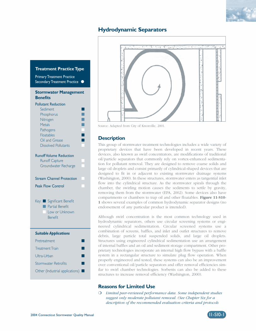
2004 Connecticut Stormwater Quality Manual 11-S10-1
Hydrodynamic Separators
DescriptionThis group of stormwater treatment technologies includes a wide variety ofproprietary devices that have been developed in recent years. Thesedevices, also known as swirl concentrators, are modifications of traditionaloil/particle separators that commonly rely on vortex-enhanced sedimenta-tion for pollutant removal. They are designed to remove coarse solids andlarge oil droplets and consist primarily of cylindrical-shaped devices that aredesigned to fit in or adjacent to existing stormwater drainage systems(Washington, 2000). In these structures, stormwater enters as tangential inletflow into the cylindrical structure. As the stormwater spirals through thechamber, the swirling motion causes the sediments to settle by gravity,removing them from the stormwater (EPA, 2002). Some devices also havecompartments or chambers to trap oil and other floatables. Figure 11-S10-1 shows several examples of common hydrodynamic separator designs (noendorsement of any particular product is intended).
Although swirl concentration is the most common technology used inhydrodynamic separators, others use circular screening systems or engi-neered cylindrical sedimentation. Circular screened systems use acombination of screens, baffles, and inlet and outlet structures to removedebris, large particle total suspended solids, and large oil droplets.Structures using engineered cylindrical sedimentation use an arrangementof internal baffles and an oil and sediment storage compartment. Other pro-prietary technologies incorporate an internal high flow bypass with a bafflesystem in a rectangular structure to simulate plug flow operation. Whenproperly engineered and tested, these systems can also be an improvementover conventional oil/particle separators and offer removal efficiencies sim-ilar to swirl chamber technologies. Sorbents can also be added to thesestructures to increase removal efficiency (Washington, 2000).
Reasons for Limited Use❍ Limited peer-reviewed performance data. Some independent studies
suggest only moderate pollutant removal. (See Chapter Six for adescription of the recommended evaluation criteria and protocols
Treatment Practice Type
Primary Treatment PracticeSecondary Treatment Practice �
Stormwater ManagementBenefitsPollutant Reduction
Sediment �
Phosphorus �
Nitrogen �
Metals �
Pathogens �
Floatables �
Oil and Grease �
Dissolved Pollutants �
Runoff Volume ReductionRunoff Capture �
Groundwater Recharge �
Stream Channel Protection �
Peak Flow Control �
Key: � Significant Benefit� Partial Benefit� Low or Unknown
Benefit
Suitable Applications
Pretreatment �
Treatment Train �
Ultra-Urban �
Stormwater Retrofits �
Other (Industrial applications) �
Source: Adapted from City of Knoxville, 2001.

2004 Connecticut Stormwater Quality Manual11-S10-2
for consideration of these technologies as primarytreatment practices).
❍ Cannot effectively remove soluble pollutants orfine particles.
❍ Can become a source of pollutants due to re-suspension of sediment unless maintainedregularly. Maintenance often neglected (“out of sight and out of mind”).
Suitable Applications❍ Where higher sediment and pollutant removal
efficiencies are required over a range of flowconditions, as compared to conventional oil/particle or oil/grit separators.
❍ For limited removal of trash, debris, oil andgrease, and sediment from stormwater runofffrom relatively small impervious areas with high traffic volumes or high potential for spillssuch as:
❑ Parking lots
❑ Streets
❑ Truck loading areas
❑ Gas stations
❑ Refueling areas
❑ Automotive repair facilities
❑ Fleet maintenance yards
❑ Commercial vehicle washing facilities
❑ Industrial facilities
❍ To provide pretreatment for other stormwater treatment practices.
❍ For retrofit of existing stormwater drainage systems, particularly in highly developed (ultra-urban) areas where larger conventional treatmentpractices are not feasible or where abovegroundtreatment practices are not an option.
Design ConsiderationsDue to the proprietary nature of these products, hydro-dynamic separators should be designed according tothe manufacturer’s recommendations. Some generaldesign considerations for these devices include:
Drainage Area: The recommended maximum con-tributing drainage area to individual devices varies bymanufacturer, model, etc.
Sizing/Design: In most instances, hydrodynamicseparators should be used in an off-line configurationto treat the design water quality flow (peak flow asso-ciated with the design water quality volume).Upstream diversion structures can be used to bypasshigher flows around the device. Sizing based on flowrate allows these devices to provide treatment withina much smaller area than conventional volume-basedstormwater treatment practices such as ponds, wet-lands, and infiltration practices. Potential mosquitoentry points should be sealed (adult female mosqui-toes can use openings as small as 1/16 inch to accesswater for egg laying). To avoid funneling amphibiansinto treatment chambers, where they are killed,Hydrodynamic separators should be used in conjunc-tion with Cape Cod curbing or other similar curbingthat allows amphibians to climb.
Performance: Performance is dependent on manyvariables such as particle size, sediment concentra-tion, water temperature, and flow rate. Hydrodynamicseparators should be sized and compared based onperformance testing of comparable size particles,influent concentrations, and testing protocols.Comparative performance testing that establishes aperformance curve over the full operating range ofthe technology should be considered a prerequisite toany meaningful performance based sizing.
Maintenance: Frequent inspection and cleanout iscritical for proper operation of hydrodynamic separa-tors. Structures that are not maintained can besignificant sources of pollution. Recommended main-tenance requirements and schedules vary withmanufacturer, but in general these devices need to becleaned quarterly. Typical maintenance includesremoval of accumulated oil and grease, floatables,and sediment using a vacuum truck or other ordinarycatch basin cleaning equipment.
Design plans for hydrodynamic separators shouldidentify detailed inspection and maintenance require-ments, inspection and maintenance schedules, andthose parties responsible for maintenance.
Sediment Disposal: Polluted water or sedimentremoved from these devices should be properly handled and disposed in accordance with local, state,and federal regulations. Before disposal, a detailedchemical analysis of the material should be performedto determine proper methods for storage and disposal.

2004 Connecticut Stormwater Quality Manual 11-S10-3
Figure 11-S10-1 Examples of Common Hydrodynamic Separator Designs
Diversion weir
Profile ViewProfile View
Plan View
Section View
Plan View
Section View
Inlet
InletOil
Outlet
Outlet
Outlet
Diversion weir High-flow bypass
Vented manhole
Portion of unit outsidethe separation chambercollects cleanstormwater
Separation chamberwith screen around it
Inlet
Riser
SumpSediments
Vented manhole (typical)
3”
Aluminumtank
Bypass
Oil storage
Treatment chamber
Design Example 1
Design Example 5
Design Example 2
Design Example 3 Design Example 4
Oil chamber
Gritchamber
Inlet
Flow control chamber
Outletchamber
Outlet
Oil barrierWeir plates
Plan ViewSwirl concentrator
Source: Adapted from City of Knoxville, 2001.

2004 Connecticut Stormwater Quality Manual11-S10-4
ReferencesCity of Knoxville. 2001. Knoxville BMP Manual. Cityof Knoxville Engineering Department, Knoxville,Tennessee.
United States Environmental Protection Agency (EPA).2002. National Menu of Best Management Practicesfor Stormwater Phase II. URL: http://www.epa.gov/npdes/menuofbmps/menu.htm,Last Modified January 24, 2002.
Washington State Department of Ecology(Washington). 2000. Stormwater Management Manualfor Western Washington, Final Draft. Olympia,Washington.

2004 Connecticut Stormwater Quality Manual 11-S11-1
Media Filters
DescriptionMedia filters are an evolution of fixed bed sand filtration technology. In thistype of treatment practice, media is placed within filter cartridges that aretypically enclosed in underground concrete vaults. Stormwater is passedthrough the media, which traps particulates and/or soluble pollutants.Various materials may be used as filter media including pleated fabric, acti-vated charcoal, perlite, amended sand and perlite mixes, and zeolite.Selection of filter media is largely a function of the pollutants targeted forremoval. Pretreatment prior to the filter media is typically necessary forstormwater with high total suspended solids, hydrocarbon, and debrisloadings that may cause clogging and premature filter failure (Washington,2000). Maintenance requirements for filter media include sediment removaland replacement of media cartridges. Figure 11-S11-1 shows an exampleof a common media filter design (no endorsement of any particular prod-uct is intended).
Reasons for Limited Use❍ Limited peer-reviewed performance data available. (See Chapter Six
for a description of the recommended evaluation criteria and proto-cols for consideration of these technologies as primary treatmentpractices).
❍ Require frequent maintenance and replacement. Can become asource of pollutants unless maintained frequently.
❍ Susceptible to clogging. Pretreatment is required for high solidsand/or hydrocarbon loadings and debris that could cause prematurefailure due to clogging.
Suitable Applications❍ Specialized applications such as industrial sites for specific target pol-
lutants (i.e., organics, heavy metals, and soluble nutrients) that arenot easily removed by other conventional treatment practices.
Treatment Practice Type
Primary Treatment PracticeSecondary Treatment Practice �
Stormwater ManagementBenefitsPollutant Reduction
Sediment �
Phosphorus �
Nitrogen �
Metals �
Pathogens �
Floatables �
Oil and Grease �
Dissolved Pollutants �
Runoff Volume ReductionRunoff Capture �
Groundwater Recharge �
Stream Channel Protection �
Peak Flow Control �
Key: � Significant Benefit� Partial Benefit� Low or Unknown
Benefit
Suitable Applications
Pretreatment �
Treatment Train �
Ultra-Urban �
Stormwater Retrofits �
Other (Industrial applications) �
Source: Adapted from Stormwater Management, Inc.

2004 Connecticut Stormwater Quality Manual11-S11-2
❍ For retrofit of existing stormwater drainage sys-tems, particularly in highly developed(ultra-urban) areas where larger conventionaltreatment practices are not feasible or whereaboveground treatment practices are not anoption.
❍ For pretreatment or as part of a stormwatertreatment train in conjunction with otherstormwater management practices.
Design ConsiderationsDue to the proprietary nature of these products,media filters should be designed according to themanufacturer’s recommendations. Some generaldesign considerations for media filters include:
Sizing/Design: Media filters should primarily be usedin an off-line configuration to treat either the designwater quality volume or the design water quality flow(peak flow associated with the design water qualityvolume). Upstream diversion structures or bypass sys-tems built into the unit are used to bypass higherflows around the device. The size and number of fil-ter cartridges are determined based upon theanticipated solids loading rate and design water qual-ity flow. Filter media are selected based on pollutantsof concern. Potential mosquito entry points should besealed (adult female mosquitoes can use openings assmall as 1/16 inch to access water for egg laying).
Maintenance: Frequent inspection and cleanout iscritical for proper operation of media filters. Structuresthat are not maintained can be significant sources ofpollution. Manufacturer’s operation and maintenanceguidelines should be followed to maintain designflows and pollutant removals. Typical maintenanceincludes removal of accumulated oil and grease, float-ables, and sediment from the filter chamber andreplacement of the filter cartridges.
Plans for media filters should identify detailed inspec-tion and maintenance requirements, inspection andmaintenance schedules, and those parties responsiblefor maintenance.
Sediment Disposal: Polluted water or sedimentremoved from these devices should be properly han-dled and disposed in accordance with local, state, andfederal regulations. Before disposal, a detailed chem-ical analysis of the material should be performed todetermine proper methods for storage and disposal.
ReferencesStormwater Management Inc., URL: http://www.stormwatermgt.com/.
United States Environmental Protection Agency (EPA).2002. National Menu of Best Management Practicesfor Stormwater Phase II. URL: http://www.epa.gov/npdes/menuofbmps/menu.htm,Last Modified January 24, 2002.
Washington State Department of Ecology(Washington). 2000. Stormwater ManagementManual for Western Washington, Final Draft.Olympia, Washington.

Figure 11-S11-1 Typical Media Filter Design
Source: Adapted from Stormwater Management, Inc.
2004 Connecticut Stormwater Quality Manual 11-S11-3
Access doors
Outlet pipe
Flow spreader
Ladder
Flow spreader
Inlet pipe
Energy dissipatorFiltration bay
Stormfilter cartridge
High flow bypass
Filtered waterdischarge

2004 Connecticut Stormwater Quality Manual 11-S12-1
Underground Infiltration Systems
DescriptionA number of underground infiltration systems, including premanufacturedpipes, vaults, and modular structures, have been developed as alternativesto infiltration trenches and basins for space-limited sites and stormwaterretrofit applications. Similar to traditional infiltration trenches and basins,these systems are designed to capture, temporarily store, and infiltrate thewater quality volume over several days. These devices are typicallydesigned as off-line systems, but can also be used to retain and infiltratelarger runoff volumes. Performance of underground infiltration systemsvaries by manufacturer and system design. These systems are currentlyconsidered secondary treatment practices due to limited field performancedata, although pollutant removal efficiency is anticipated to be similar tothat of infiltration trenches and basins. Figure 11-S12-1 shows severalexamples of common underground infiltration systems.
Reasons for Limited Use❍ Limited available monitoring data and undocumented field longevity.
❍ Potential failure due to improper siting, design (including adequatepretreatment), construction, and maintenance.
❍ Susceptible to clogging by sediment.
❍ Risk of groundwater contamination depending on subsurface condi-tions, land use, and aquifer susceptibility.
❍ Not suitable for stormwater runoff from land uses or activities withthe potential for high sediment or pollutant loads.
Suitable Applications❍ As an alternative to traditional infiltration trenches and basins for
space-limited sites. These systems can be installed under parking lotsand other developed areas, provided that the system can be accessedfor maintenance purposes.
Treatment Practice Type
Primary Treatment PracticeSecondary Treatment Practice �
Stormwater ManagementBenefitsPollutant Reduction
Sediment �
Phosphorus �
Nitrogen �
Metals �
Pathogens �
Floatables �
Oil and Grease �
Dissolved Pollutants �
Runoff Volume ReductionRunoff Capture �
Groundwater Recharge �
Stream Channel Protection �
Peak Flow Control �
Key: � Significant Benefit� Partial Benefit� Low or Unknown
Benefit
Suitable Applications
Pretreatment �
Treatment Train �
Ultra-Urban �
Stormwater Retrofits �
Other �
Source: CULTEC, Inc.

2004 Connecticut Stormwater Quality Manual11-S12-2
❍ Useful in stormwater retrofit applications or aspart of a stormwater treatment train to provideadditional groundwater recharge and storagevolume to attenuate peak flows.
Design ConsiderationsThe materials of construction, configuration, and lay-out of underground infiltration systems varyconsiderably depending on the system manufacturer.Specific design criteria and specifications for thesesystems can be obtained from system manufacturersor vendors. General design elements common to mostof these systems are summarized below. The readershould refer to the Infiltration Practices section of thischapter for additional information on siting, design,construction, and maintenance considerations.
Siting: Underground infiltration systems are gener-ally applicable to small development sites (typicallyless than 10 acres) and should be installed in loca-tions that are easily accessible for routine andnon-routine maintenance. These systems should notbe located in areas or below structures that cannotbe excavated in the event that the system needs tobe replaced. Similar to infiltration trenches andbasins, underground infiltration systems should onlybe used with soils having suitable infiltration capac-ity (as confirmed through field testing) and for landuses, activities, or areas that do not pose a risk ofgroundwater contamination.
Pretreatment: Appropriate pretreatment (e.g.,oil/particle separator, hydrodynamic device, catchbasin inserts, or other secondary or primary treatmentpractices) should be provided to remove sediment,floatables, and oil and grease.
Design Volume: Underground infiltration structuresshould be designed as off-line practices to infiltratethe entire water quality volume. A flow bypass struc-ture should be located upgradient of the infiltrationstructure to convey high flows around the structure.
Draining Time: Infiltration structures should bedesigned to completely drain the water quality vol-ume into the soil within 48 hours after the storm eventand completely dewater between storms. A minimumdraining time of 6 hours is recommended to ensureadequate pollutant removal. Standing water for longerthan 5 days can lead to potential mosquito-breedingproblems. Potential mosquito entry points should besealed (adult female mosquitoes can use openings assmall as 1/16 inch to access water for egg laying).
Infiltration Rate: The minimum acceptable field-measured soil infiltration rate is 0.3 inches per hour.Field-measured soil infiltration rates should notexceed 5.0 inches per hour. This generally restrictsapplication to soils of NRCS Hydrologic Soil Group A.Some Group B soils may be suitable if field-measuredinfiltration rates exceed 0.3 inches per hour.

Figure 11-S12-1 Examples of Underground Infiltration Systems
2004 Connecticut Stormwater Quality Manual 11-S12-3
Plastic chamber withopen bottom
Crushed, washed stone Filter fabric
Elevation
Underground Plastic Chamber System
Modular Underground Infiltration System
Compacted fill
Surfacing
Pretreatment
Outflow pipe (fordetention system)
Crushed, washedstone layer
Compacted backfill
Geotextile
Modular storage structurelined with geotextile(exfiltration)
Elevation
Source: Invisible Structures, Inc. and CULTEC, Inc.

2004 Connecticut Stormwater Quality Manual 11-S13-1
Alum Injection
DescriptionAlum injection is the addition of aluminum sulfate (alum) solution tostormwater before discharging to a receiving water body or stormwatertreatment practice. When alum is injected into stormwater it binds withsuspended solids, metals, and phosphorus and forms aluminum phosphateand aluminum hydroxide precipitates. These precipitates settle out of thewater column and are deposited in the bottom sediments in a stable, inac-tive state (referred to as “floc”).
The injection of liquid alum into storm sewers has been used to reduce thewater quality impacts of stormwater runoff to lakes and other receivingwater bodies, particularly to reduce high phosphorus levels and addresseutrophic conditions (EPA, 2002). Alum injection systems are commonlyused in some parts of the country as stormwater retrofits for existing dis-charges to lakes and ponds, but may also be used as pretreatment forstormwater ponds and other treatment practices (ASCE, 2001). Alum addi-tion should be considered only after all other best management practiceshave been implemented.
Reasons for Limited Use❍ Limited long-term performance data.
❍ Requires ongoing operation unlike most other stormwater treatmentpractices.
❍ Improper dosing of chemicals may have negative impacts on down-stream water bodies.
❍ Increases the volume of sediment/floc (and associated pollutant concentrations) that must be disposed of.
❍ Typically not cost effective for drainage areas less than 50 acres.
❍ Alum application may be approved as part of a state stormwater permit or could require an individual state permit. The DEP WaterManagement Bureau should be contacted for further permit guidance.
Treatment Practice Type
Primary Treatment PracticeSecondary Treatment Practice �
Stormwater ManagementBenefitsPollutant Reduction
Sediment �
Phosphorus �
Nitrogen �
Metals �
Pathogens �
Floatables �
Oil and Grease �
Dissolved Pollutants �
Runoff Volume ReductionRunoff Capture �
Groundwater Recharge �
Stream Channel Protection �
Peak Flow Control �
Key: � Significant Benefit� Partial Benefit� Low or Unknown
Benefit
Suitable Applications
Pretreatment �
Treatment Train �
Ultra-Urban �
Stormwater Retrofits �
Other �
Source: Photo courtesy of Adell Donaghue.

2004 Connecticut Stormwater Quality Manual11-S13-2
Suitable Applications❍ Best suited to situations where a large volume
of water is stored in one area.
❍ As part of a stormwater treatment train or pretreatment step to further reduce turbidity and fine suspended solids.
❍ For existing stormwater discharges to existingponds and lakes, particularly in highly devel-oped areas, where new stormwater treatmentpractices or other treatment options are not feasible.
Design ConsiderationsDesign: Alum injection systems typically consist of aflow-weighted dosing system designed to fit inside astorm sewer manhole, remotely located alum storagetanks, and a downstream pond or treatment practicethat allows alum and pollutants to settle out (EPA,2002). Alum dosage rates generally range between 5 and 10 milligrams per liter of alum solution and are determined on a flow-weighted basis duringstorm events. Lime is often added to raise the pH(between 8 and 11) and enhance pollutant settling. Jartesting is recommended to determine alum dosingrates and the need for pH control. Injection points inthe storm drainage system should be approximately100 feet upstream of the discharge point (ASCE,2001). In addition to the settling pond, a separate floccollection pump-out facility is recommended toreduce the chance of resuspension and transport offloc to receiving waters by pumping floc to the sani-tary sewer or onto nearby upland areas (withappropriate local, state, and federal regulatoryapproval, as necessary).
Operation and Maintenance: Typical operation andmaintenance requirements for alum injection systemsinclude maintenance of pump equipment, power,chemical replacement, routine inspections, and
equipment replacement (doser and pump-out facil-ity). A trained operator should be on-site to adjust thechemical dosage and regulate flows, if necessary.Alum injection systems also require continued moni-toring of water quality to detect potential negativeimpacts to receiving waters. The settling basin orpond should be dredged periodically to dispose ofaccumulated floc.
Cost Considerations: Alum injection is a relativelyexpensive and labor-intensive treatment practice.Construction costs depend on watershed size and thenumber of outfalls treated, but construction costs gen-erally range from $135,000 to $400,000. Due to thehigh construction cost, alum injection is not costeffective for drainage areas less than 50 acres.Operation and maintenance costs can vary from$6,500 to $50,000 per year depending on the size ofthe system (Harper and Herr, 1996).
ReferencesAmerican Society of Civil Engineers (ASCE). 2001. AGuide for Best Management Practice (BMP) Selectionin Urban Developed Areas. Urban Water InfrastructureManagement Committee’s Task Committee forEvaluating Best Management Practices. Reston,Virginia.
Harper, H.H. and J.L. Herr. 1996. Alum Treatment ofStormwater Runoff: The First Ten Years.Environmental Research and Design. Orlando,Florida.
United States Environmental Protection Agency (EPA).2002. National Menu of Best Management Practicesfor Stormwater Phase II. URL: http://cfpub.epa.gov/npdes/stormwater/menuofbmps/post_3.cfm, Last Modified August 15, 2002.