chapter 11 introduction to devicenet. devicenet purpose open network link low-level devices to plcs...
TRANSCRIPT
Chapter 11
Introduction to DeviceNet

DeviceNet Purpose
• Open network
• Link low-level devices to PLCs– Sensors– Pushbutton stations– Distributed I/O blocks– Intelligent motor started overloads– Variable frequency drives

DeviceNet Open Network
• Open network
• Network devices (nodes) can be purchased from many different vendors
• Network managed by Open DeviceNet Vendors Association (ODVA)– ODVA.ORG

DeviceNet Advantage
• Save wiring costs– Rather than run power wires separately to each
device– Rather than run signal wires from each field device
separately back to PLC, I/O module connect devices directly to a network
– One cable with four wires• Two power wires• Two signal wires

Field Devices More Intelligent
• Traditional systems – A photo switch counting pieces as they pass
on a conveyer was wired directly into an input module.
• Counter programmed on ladder to track parts’ count
• Counter done bit triggered output point to control field action

DeviceNet Advantage
• Many DeviceNet devices are intelligent.
• Photo switch has counters and timers incorporated into sensor.
• PLC does not need to have timer or counter on ladder.
• When timer or counter is done, the action is carried out through RSNetWorx for DeviceNet software to trigger field device across the network.

DeviceNet Components
• PLC with DeviceNet scanner• RSNetWorx software for DeviceNet• Trunk line• Drop lines• Nodes• Minimum one power supply• Two 121-ohm ¼-watt termination resistors• Up to 64 nodes
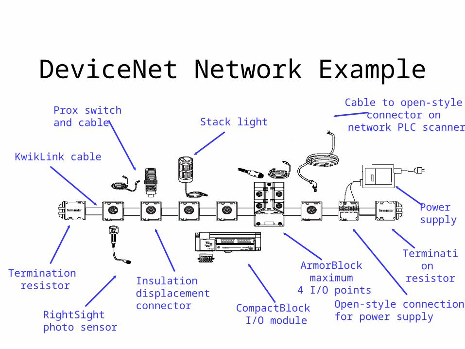
DeviceNet Network ExampleCable to open-style
connector on network PLC scanner
KwikLink cable
Termination resistor
RightSightphoto sensor
Insulation displacement connector CompactBlock
I/O module
ArmorBlock maximum 4 I/O points
Powersupply
Termination resistor
Open-style connection for power supply
Prox switch and cable Stack light

Sample of Some DeviceNet Media Components
Thick round drop line cable
KwikLink drop line cable
KwikLink flat trunk line cable insulation displacement connector
Device port
T-port
KwikLink flat trunk line cable
DeviceLink
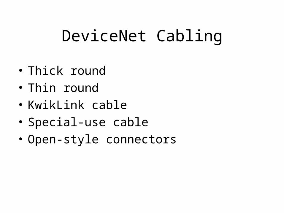
DeviceNet Cabling
• Thick round
• Thin round
• KwikLink cable
• Special-use cable
• Open-style connectors

Thick Round Cable
• Used for trunk line
• T-ports used to connect from trunk line to drop lines
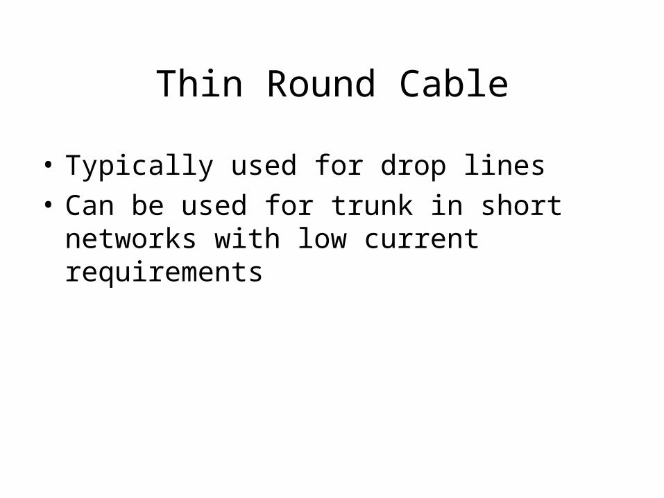
Thin Round Cable
• Typically used for drop lines
• Can be used for trunk in short networks with low current requirements
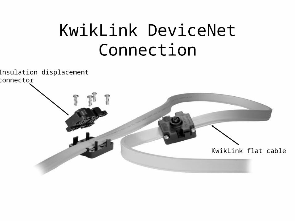
KwikLink DeviceNet Connection
KwikLink flat cable
Insulation displacement connector
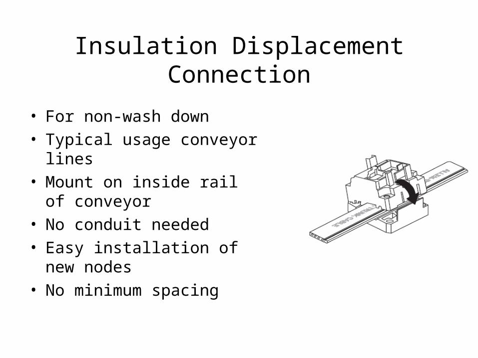
Insulation Displacement Connection
• For non-wash down • Typical usage conveyor lines• Mount on inside rail of
conveyor• No conduit needed• Easy installation of new
nodes• No minimum spacing

DevicePort
• Passive 4- or 8-point taps
• Connected to trunk line by drop line
• Previous slide showed an 8-point DevicePort
• Nodes connected to DevicePort by drop lines

T-port
• Used to connect drop line to trunk line
• Drop line connected to DevicePort and then on to multiple nodes
• Drop line connected directly to node
• Maximum drop line length 20 feet
DeviceLink
• Adapter to interface non-DeviceNet devices to network
• 2- or 3-wire 24-V sensors
• Mechanical limit switches
• Any non-DeviceNet device with relay contacts
• One required for each non-DeviceNet node

Additional Media
• Refer to the DeviceNet Media catalog for a complete listing of available products.

Maximum Trunk Line Length (1 of 2)
• Maximum cable distance between any two nodes
• Not necessarily actual length of backbone
• Maximum length determined by cable type and baud rate

Maximum Trunk Line Length (2 of 2)

Trunk Line Calculation One
Node number

Example One
• Left terminating resistor to node 1 is 12 feet.
• Drop line node 1 is 2 feet.
• Right terminating resistor to node 12 is also 12 feet.
• Node 12 drop line is 2 feet.
• From node 1 drop line to node 12 drop line is 800 feet.

Trunk Line Calculation (1 of 2)
• For this example, trunk line length is maximum length of cable between terminating resistors.

Trunk Line Calculation (2 of 2)
• 12 + 800 + 12 = 824 feet
• Refer to table for maximum baud rate of network.

Maximum Trunk Line Length
Trunk line length is over 820 feet so maximum baud rate for this network is 125 K.
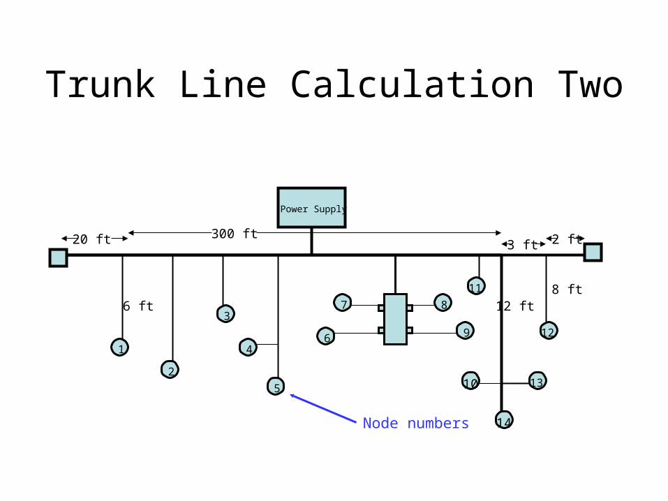
Trunk Line Calculation Two
Power Supply
1
2
3
4
5
6
7 8
9
10
11
12
13
14
6 ft
2 ft
8 ft
300 ft20 ft
12 ft
3 ft
Node numbers

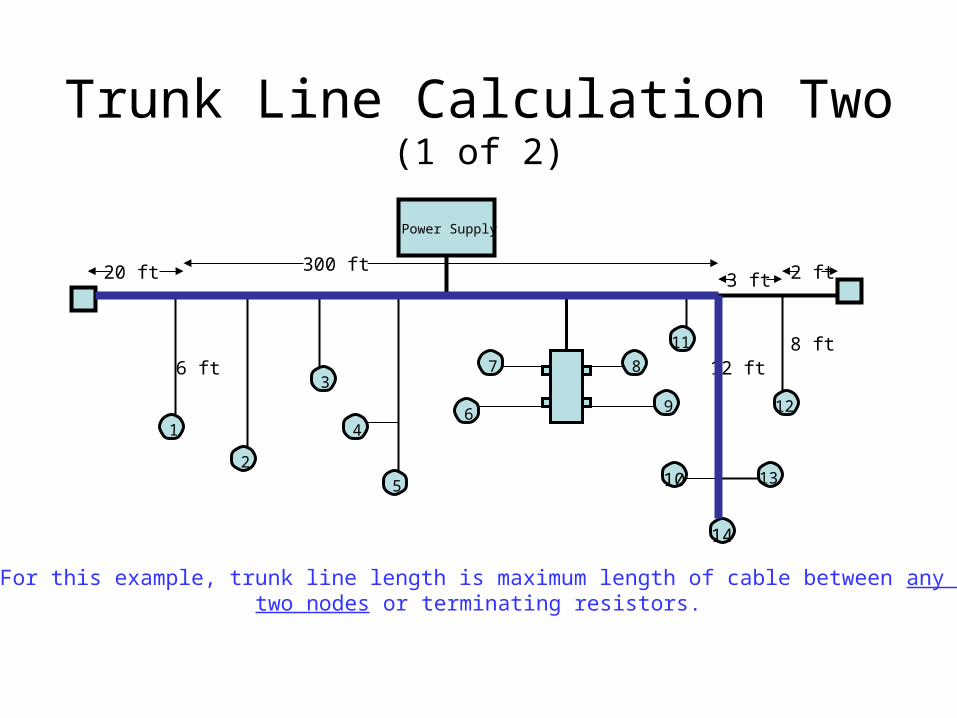
Example Two
• Left terminating resistor to node 1 drop line is 20 feet.
• Node 1 drop line is 6 feet.• Right terminating resistor to node 12 drop line is 2
feet.• Node 12 drop line is 8 feet.• Trunk line from node 12 drop to node 14 drop line is
3 feet.• Node 14 drop line is 12 feet.• Node 1 trunk line to node 14 is 300 feet.

Trunk Line Calculation
• For this example, trunk line length is maximum length of cable between any two nodes or terminating resistors.
• Assume round thick trunk line.
• Look at network again.
Trunk Line Calculation Two (1 of 2)
Power Supply
1
2
3
4
5
6
7 8
9
10
11
12
13
14
6 ft
2 ft
8 ft
300 ft20 ft
12 ft
3 ft
For this example, trunk line length is maximum length of cable between any two nodes or terminating resistors.

Trunk Line Calculation Two (2 of 2)
• The longest cable distance is between the left terminating resistor and node 14.
• For this example, the distance between terminating resistors would not be the correct calculation.
• 20 + 300 + 12 = 332 feet• Refer to table for maximum baud rate of
network.
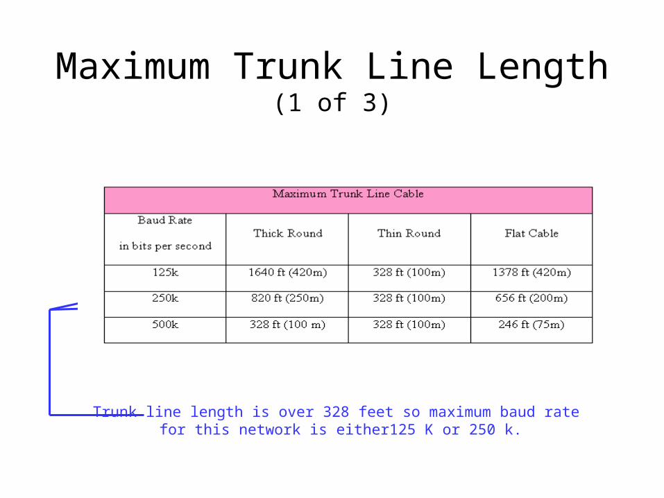
Maximum Trunk Line Length (1 of 3)
Trunk line length is over 328 feet so maximum baud rate for this network is either125 K or 250 k.

Maximum Trunk Line Length (2 of 3)
• The rule is to go back 20 feet from the termination resistors and see if there is a drop line that is longer.– If a drop is longer, then it must be included in
the trunk line calculation.– Remember maximum drop line length is 20
feet.

15
8
43
7
20 feet
Maximum Trunk Line Length (3 of 3)
• Terminating resistor and node 00 is 3 feet.
• Node 00 and node 1 is 4 feet.
• Trunk line to node 7 is 15 feet.
• 15 foot drop is longer than 3 +4 for trunk.

Cumulative Drop Line Length (1 of 2)
• Sum of all drop lines
• Maximum drop line length to any one node– 20 feet
• Cumulative drop line length also determines network baud rate

Cumulative Drop Line Length (2 of 2)
Text figure 11-30
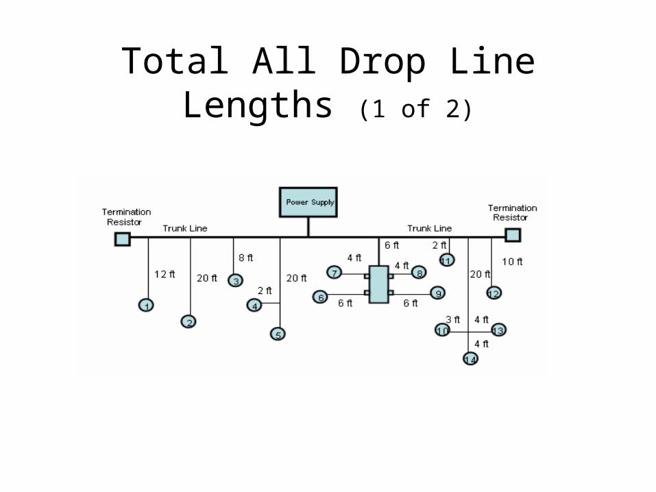
Total All Drop Line Lengths (1 of 2)

Total All Drop Line Lengths (2 of 2)
• Cumulative length is 131 feet.
• Nodes 10, 13, and 14 exceed the 20-foot maximum drop to any 1 node.
• Shorten up cable.
• Cumulative drop line length is now 127 feet.
• Refer to the table for maximum baud rate for network.

Cumulative Drop Line Length
Cumulative drop line length is 127 feet.
Power Calculations
• Add up total device current
• Determine trunk line length
• Cable type
• How many power supplies and where mounted
• Look up tables for power allowed on network
• Full calculation method available for additional accuracy

Common Problems With DeviceNet Networks (1 of 2)
• Improper installation– Trunk line length correct?– Cumulative drop line length correct?– Power supply proper size?– Overdriving network with too much information flow?
• Refer to DeviceNet Cable System Planning and Installation Manual from Rockwell Automation Web site.

Common Problems With DeviceNet Networks (2 of 2)
• Network modification after installation– Trunk line length recalculated?– Cumulative drop line length recalculated?– Power supply recalculated?– Overdriving network with too much
information flow?

DeviceNet Interface

DeviceNet open-style cable connection point
Set baud rate
Set interface card’s node
Status LEDs
FlexLogix PLC DeviceNet Daughter Card

CompactLogix DeviceNet Scanner
DeviceNet scannerOpen-style cable connection
CompactLogix processor
CompactLogix is a member of the ControlLogix family.
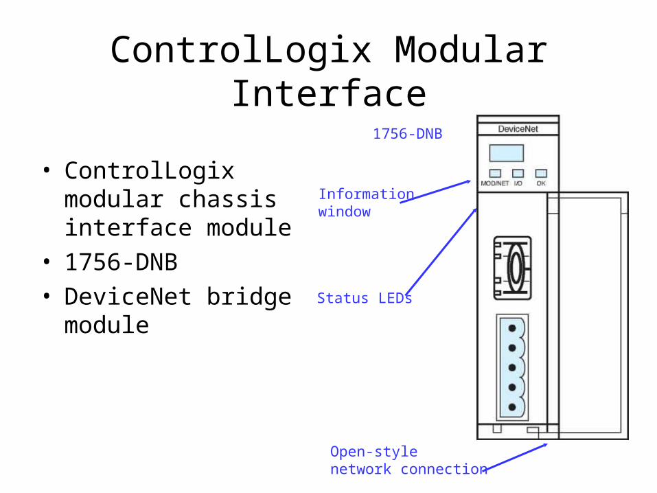
ControlLogix Modular Interface
• ControlLogix modular chassis interface module
• 1756-DNB
• DeviceNet bridge module
Informationwindow
Status LEDs
Open-style network connection
1756-DNB

Example of Rockwell Automation PLC DeviceNet Interface Modules
• SLC 500 DeviceNet scanner– 1747-SDN
• PLC 5 DeviceNet scanner– 1771-SDN

Example of General Electric PLC DeviceNet Interface Modules
• Series 90-30 PLCs– DeviceNet master module– IC693DNM200
• VersaMax PLC– Remote I/O DeviceNet network interface– IC200DB1001

Personal Computer DeviceNet Interface
• Computer type determines interface needed.– Notebook uses PCMCIA such as a Rockwell
Automation 1784-PCD.– Desktop or industrial computer would require
a DeviceNet 1784-expansion card.– Computer with serial port could use Rockwell
Automation 1770-KFD interface box.

1770-KFD InterfaceDesktop or notebook computer with serial port
1770-KFD Interface cable
Open-style connector to DeviceNet network
Interfacecable plug
KFD to serial port interface cable
SLC 500 1747-SDN

Open-style connectorto DeviceNet network
PCMCIA interface card 1784-PCD
SLC 500 1747-SDNNotebook
personal computerInterface cables
1784-PCD Card

Use ControlLogix PLC as a Bridge (1 of 2)
• Most popular interface to PLC for upload, download, on-line editing is Ethernet
• Ethernet interface card in ControlLogix chassis(1756- ENBT)
• A 1756-DNB or DeviceNet bridge module in ControlLogix chassis to communicate with DeviceNet

Use ControlLogix PLC as a Bridge (1 of 2)
• Use RSLinx Ethernet driver to get to Ethernet interface module
• Bridge across ControlLogix backplane to DeviceNet Bridge module (1756-DNB)
• Out DNB to DeviceNet network
• No separate DeviceNet interface required

RSNetWorx Software
• RSNetworx for DeviceNet software– Set up network– Map data flowing on network– Program, monitor, or modify device
parameters

RSNetWorx for DeviceNet

RSNetWorx View of DeviceNet
Terminationresistor
Terminationresistor
Power supply not shown in RSNetWorx
Trunk line
Drop line
Network scanner
Node address
Device or nodeon network

DeviceNet Scan List
• RSNetWorx software• Scan List is part of scanner properties.• Any device that is on the network that is to be
scanned by the PLC scanner must be in the Scan List.
• Network devices are not mapped until placed in the Scan List by programmer.– Auto mapping– Manual mapping

Add or remove single device to or from Scan List
Auto map devices when add to scan list
Scan List tab
Scan List
Electronic keying
ControlLogixDNB scannerproperties screen
DeviceNet PLC Scanner Properties
Add or remove all devices to or from Scan List

Available Devices on Network
• When going on-line with a network scanner, like a 1756-DNB, scanner will recognize devices currently present on network.– These devices or nodes will be listed in the
Available Devices view.– These devices are not in the scan list at this
time.

Auto Map Devices When Add to Scan List
• Do you want the device(s) to be auto-mapped when added to the scan list?
• If Automap is selected, you have no control of how devices are mapped.
• If you uncheck Automap, then devices can be manually mapped by the programmer.

Electronic Keying
• How close does a replacement device have to be to the original when replaced?– Device type– Vendor– Product code– Major revision– Minor revision
• Minor revision or higher

DeviceNet Data Mapping
ControlLogix

ControlLogix 1756-DNB Mapping
Scannerproperties
Input devices in Scan List
Input tab
ControlLogix processor tags or addresses where data is mapped.
Data mapping for each node
Unused processor memory. Can bemanually mapped later.
Click here to unmap a device.

DeviceNet Data Mapping
• ControlLogix is a 32-bit PLC.– All tags will be either 32 bits wide or a:
• Word, called an integer (INT) which is16 bits• Byte, called a short integer (SINT) which is 8 bits
• Minimum memory allocation for any DeviceNet device is a SINT.
• Node 6 is a bulletin 160 Allen-Bradley Drive.– Drive has two words of data.
• Drive status information as single bits• Drive speed feedback represented as 0 to 32767

32 Bits
16 Bits
078151631
ControlLogix Input Mapping
Node 6 Drive Input Status word
Node 6 Drives Speed Feedback word Node 4 Series 9000 Photo Electric Sensor mapping
Node 3 Series 9000 Photo Electric Sensor mapping
ControlLogix Tags

ControlLogix Processor Data Mapping or Tags (1 of 2)
• Node 6 is Bulletin 160, the variable frequency drive– Status bits mapped as upper word of
Local:1:I.Data[2].– Drive Speed Feedback word is mapped as the
lower word of Local:1:I.Data[3].

ControlLogix Processor Data Mapping or Tags (2 of 2)
• Node 4 is a Series 9000 Photo Switch mapped as the upper byte of the lower word at Local:1.I.Data[2].
• Node 3 is a Series 9000 Photo Switch mapped as the lower byte of the lower word at Local:1.I.Data[2].
DeviceNet Data Mapping
SLC 500

DeviceNet Data Mapping
• SLC 500 and PLC 5 are 16-bit computers.– All data will either be a 16-bit word or one byte.
• Minimum memory allocation for any DeviceNet device is a byte.
• Node 6 is a Bulletin 160 Allen-Bradley Drive.– Drive has two words of data.
• Drive Command information as single bits• Drive Speed Command represented as 0 to 32767

SLC 500 Output Data Mapping
1747-SDN properties view
Output devices in Scan List
SLC 500 Output Status Table where data is coming from
Output mapping tab
Click here to unmap selected device
Two words or 8 bytes currently mapped for drive at node 6
SLC 500 Processor Data Mapping
• Node 6 is Bulletin 160, the variable frequency drive– Drive Command bits word is mapped as
O:1.2.– Drive Speed Command word is mapped as
O:1.3.

Node 2 Output Mapping
• Node 8 is a Rockwell Automation 1792D compact block output module.– This compact block has four outputs.
• Output data from SLC 500 mapped to lower byte of O:1.6.
• Currently upper byte of O:1.6 is available for another device.

DeviceNet Nodes General Properties

• Right click on device on RSNetWorx screen.
• General Properties screen is displayed.– Display I/O data– Display, monitor, or modify devices
parameters– View electronic data sheet (EDS file)

Identifies this device
Current node address.Node address can be changed here.
Parameters tab
Device’s identity
EDS tab
Numbers used to identify EDS file
General Properties

Device Parameters
Parameters tab
Parameternumber
Lock identifiesread-onlyparameters Click here to
monitor parameter
Icons for uploading or downloadingto device
Monitor a single parameter or all
Current value of parameter
Device

Parameter Editing
Select parameter to edit
Options drop-down box
Select

Electronic Data Sheets
EDS Files
Electronic Data Sheets
• Typically referred to as EDS files– EDS files contain information regarding the
personality of the device.– Correct EDS file must reside in the device
before it can be a working part of the network.– EDS file must be the same firmware level as
the device.

If EDS File Is Not Current
• Go to manufacturer’s Web site and download correct file.
• Go to ODVA.ORG site and download correct file.
• EDS file numbers represented in Hex.
• Use EDS Wizard to update or register the network device.

EDS Wizard
Updating a network Device’s EDS file is toregister the file.
Click next to continue.

Register EDS File
How many files to register
After download, browse for file on you computer.
Click next to continue registration.
EDS file name represented in Hex
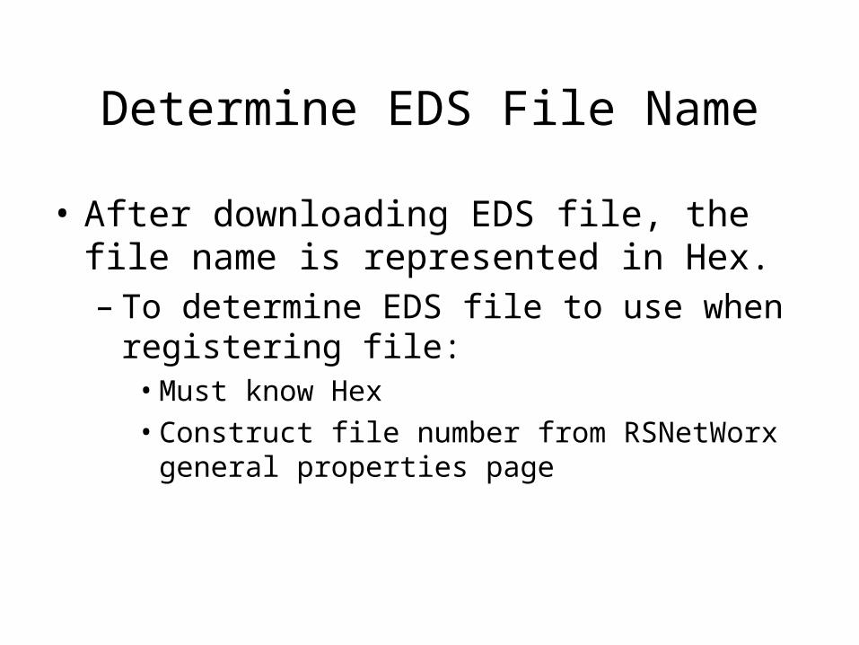
Determine EDS File Name
• After downloading EDS file, the file name is represented in Hex.– To determine EDS file to use when registering
file:• Must know Hex• Construct file number from RSNetWorx general
properties page

[1] = 0001
Convert General Properties Page Device Identity to Hex
[6] = 0006
[43] = 002B
[1.004] = 0100
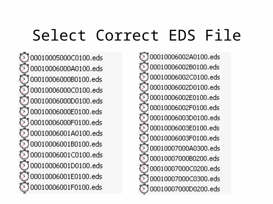
Select Correct EDS File

Select Correct EDS File