chapter 12
TRANSCRIPT
Fire Hose 397
INTRODUCTIONThe term fire hose identifies a type of flexible
tube used by firefighters to carry water underpressure from the source of supply to a point whereit is discharged. In order to be reliable, fire hoseshould be constructed of the best materials, and itshould not be used for purposes other than firefighting. Fire hose is the most used item in the fireservice. It must be flexible, be watertight, have asmooth lining, and have a durable covering (alsocalled a hose jacket). Depending on its intendeduse, fire hose is manufactured in different configu-rations such as single-jacket, double-jacket, rub-ber single-jacket, and hard-rubber noncollapsingtypes (Figure 12.1).
This chapter includes a discussion of fire hosesizes, causes of hose damage and its prevention,and general care and maintenance. The chapterdescribes the types of hose couplings and their careand use. Also covered are the different types of hoseappliances used in water movement and the toolsused in hose operations. The procedures for rollinghose, loading supply hose on apparatus, preparingfinishes, and loading preconnected attack hoselinesare discussed and demonstrated. The chapter re-views hose-lay procedures, hose-handling tech-niques, and advancing and operating hoselines.Finally the chapter ends with a discussion of theprocedures for service testing of fire hose.
FIRE HOSE SIZES[NFPA 1001: 3-3.7(a); 3-3.9(a)]
Each size of fire hose is designed for a specificpurpose. Reference made to the diameter of firehose refers to the dimensions of the inside diam-eter of the hose. Fire hose is most commonly cut
Chapter 12
Fire Hose
and coupled into lengths of 50 or 100 feet (15 m or30 m) for convenience of handling and replace-ment, but other lengths may be obtained. Theselengths are also referred to as sections, and theymust be coupled together to produce a continuoushoseline.
Intake hose is used to connect a fire depart-ment pumper or a portable pump to a nearbywater source. There are two groups within thiscategory: soft sleeve hose and hard suction hose.Soft sleeve hose is used to transfer water from apressurized water source, such as a fire hydrant, tothe pump intake (Figure 12.2). Soft sleeves areavailable in sizes ranging from 2¹�₂ to 6 inches (65mm to 150 mm). Hard suction hose (also called ahard sleeve) is used primarily to draft water froman open water source (Figure 12.3). It is also usedto siphon water from one portable tank to an-other, usually in a tanker shuttle operation.Hard suction hose is constructed of a rubberized,reinforced material designed to withstand thepartial vacuum conditions created when draft-ing. It is also available in sizes ranging from 2¹�₂
to 6 inches (65 mm to 150 mm).
NFPA 1961, Standard on Fire Hose, listsspecifications for fire hose; NFPA 1963, Standardfor Fire Hose Connections, lists specifications forfire hose couplings and screw threads. NFPA 1901,Standard for Automotive Fire Apparatus, requirespumpers to carry 15 feet (4.6 m) of large soft sleevehose or 20 feet (6 m) of hard suction hose, 1,200 feet(366 m) of 2¹�₂-inch (65 mm) or larger supply hose(hose between the water source and the attackpumper to provide large volumes of water), and 400feet (122 m) of 1¹�₂-, 1³�₄-, or 2-inch (38 mm, 45 mm,or 50 mm) attack hose (hose between the attack

398 ESSENTIALS
Figure 12.3 Hard suction hose is designed to withstand the partialvacuum of drafting.
Figure 12.1 Common types of fire hose.
Figure 12.2 A soft sleeve hose transfers water from the fire hydrant tothe pump intake.
Fire Hose 399
pumper and the nozzle used to control and extin-guish fire). These lengths and sizes may be in-creased, depending on the needs of the depart-ment.
CAUSES AND PREVENTION OF FIRE HOSEDAMAGE[NFPA 1001: 3-5.4; 3-5.4(a)]
Fire hose is a tool that is subjected to manypotential sources of damage during fire fighting.Usually little can be done at fires to provide safeusage and to protect the hose from injury. The mostimportant factor relating to the life of fire hose isthe care it gets after fires, in storage, and on the fireapparatus. Fire hose should be selected with cau-tion to ensure its lasting qualities. Even if con-structed of quality materials, it cannot enduremechanical injury, heat, mildew and mold, andchemical contacts. The life of fire hose is, however,considerably dependent upon how well the hose isprotected against these destructive causes.
Mechanical DamageFire hose may be damaged in a variety of ways
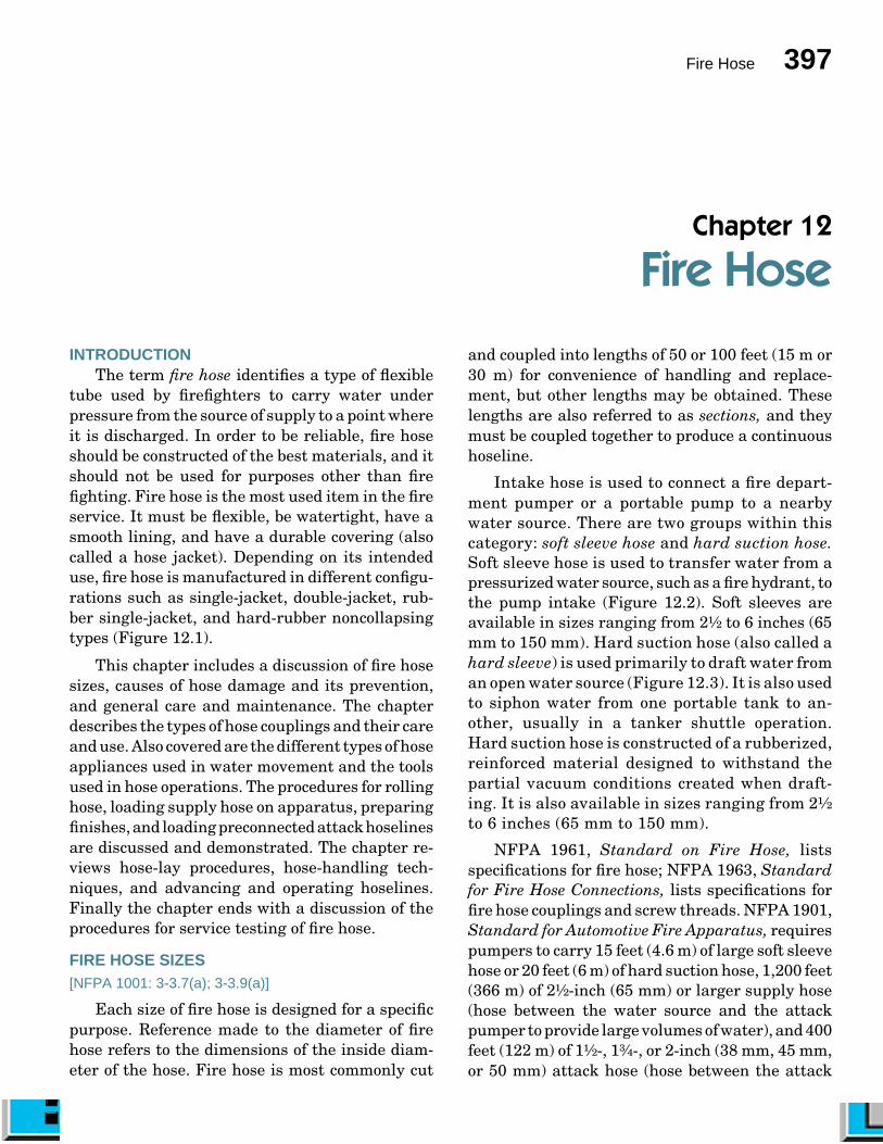
while being used at fires. Some common mechani-cal injuries are wornplaces, rips, andabrasions on thecoverings, crushedor damaged cou-plings, and crackedinner linings (Fig-ure 12.4). To pre-vent these damages,the following prac-tices are recom-mended:
• Avoid laying or pulling hose over rough,sharp edges or objects.
• Use hose ramps or bridges to protect hosefrom vehicles running over it (Figure 12.5).
• Open and close nozzles, valves, and hy-drants slowly to prevent water hammer(force created by the rapid deceleration ofwater).
• Change position of bends in hose whenreloading hose on apparatus.
Figure 12.4 Typical damage to hosethreads.
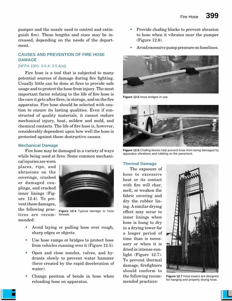
• Provide chafing blocks to prevent abrasionto hose when it vibrates near the pumper(Figure 12.6).
• Avoid excessive pump pressure on hoselines.
Figure 12.5 Hose bridges in use.
Figure 12.6 Chafing blocks help prevent hose from being damaged byapparatus vibrations and rubbing on the pavement.
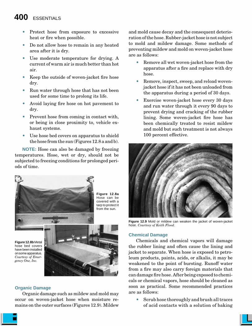
Thermal DamageThe exposure of
hose to excessiveheat or its contactwith fire will char,melt, or weaken thefabric covering anddry the rubber lin-ing. A similar dryingeffect may occur toinner linings whenhose is hung to dryin a drying tower fora longer period oftime than is neces-sary or when it isdried in intense sun-light (Figure 12.7).To prevent thermaldamage, firefightersshould conform tothe following recom-mended practices:
Figure 12.7 Hose towers are designedfor hanging and properly drying hose.
400 ESSENTIALS
• Protect hose from exposure to excessiveheat or fire when possible.
• Do not allow hose to remain in any heatedarea after it is dry.
• Use moderate temperature for drying. Acurrent of warm air is much better than hotair.
• Keep the outside of woven-jacket fire hosedry.
• Run water through hose that has not beenused for some time to prolong its life.
• Avoid laying fire hose on hot pavement todry.
• Prevent hose from coming in contact with,or being in close proximity to, vehicle ex-haust systems.
• Use hose bed covers on apparatus to shieldthe hose from the sun (Figures 12.8 a and b).
NOTE: Hose can also be damaged by freezingtemperatures. Hose, wet or dry, should not besubjected to freezing conditions for prolonged peri-ods of time.
Organic DamageOrganic damage such as mildew and mold may
occur on woven-jacket hose when moisture re-mains on the outer surfaces (Figures 12.9). Mildew
Figure 12.8b Metalhose bed covershave been installedon some apparatus.Courtesy of Emer-gency One, Inc.
Figure 12.8aHose can becovered with atarp to protect itfrom the sun.
and mold cause decay and the consequent deterio-ration of the hose. Rubber-jacket hose is not subjectto mold and mildew damage. Some methods ofpreventing mildew and mold on woven-jacket hoseare as follows:
• Remove all wet woven-jacket hose from theapparatus after a fire and replace with dryhose.
• Remove, inspect, sweep, and reload woven-jacket hose if it has not been unloaded fromthe apparatus during a period of 30 days.
• Exercise woven-jacket hose every 30 daysand run water through it every 90 days toprevent drying and cracking of the rubberlining. Some woven-jacket fire hose hasbeen chemically treated to resist mildewand mold but such treatment is not always100 percent effective.
Figure 12.9 Mold or mildew can weaken the jacket of woven-jackethose. Courtesy of Keith Flood.
Chemical DamageChemicals and chemical vapors will damage
the rubber lining and often cause the lining andjacket to separate. When hose is exposed to petro-leum products, paints, acids, or alkalis, it may beweakened to the point of bursting. Runoff waterfrom a fire may also carry foreign materials thatcan damage fire hose. After being exposed to chemi-cals or chemical vapors, hose should be cleaned assoon as practical. Some recommended practicesare as follows:
• Scrub hose thoroughly and brush all tracesof acid contacts with a solution of baking
Fire Hose 401
soda and water. Baking soda neutralizesacids.
• Remove hose periodically from the appara-tus, wash it with plain water, and dry itthoroughly.
• Test hose properly if there is the least sus-picion of damage (see Service Testing FireHose section).
• Avoid laying hose in the gutter or next tothe curb where vehicles have been parkedbecause they can drop oil from their me-chanical components and acid from batter-ies (Figure 12.10).
• Dispose of hose properly if it has been ex-posed to hazardous materials and cannot bedecontaminated.
Figure 12.10 Avoid laying hose in the gutter where it would be subjectedto debris and runoff.
GENERAL CARE AND MAINTENANCE OF FIREHOSE[NFPA 1001: 3-5.4; 3-5.4(a); 3-5.4(b)]
If fire hose is properly cared for, its life spancan be extended appreciably. The techniques ofwashing and drying and the provisions for stor-age are very important functions in the care offire hose. The following sections highlight theproper care of fire hose.
Washing HoseThe method used to wash fire hose depends on
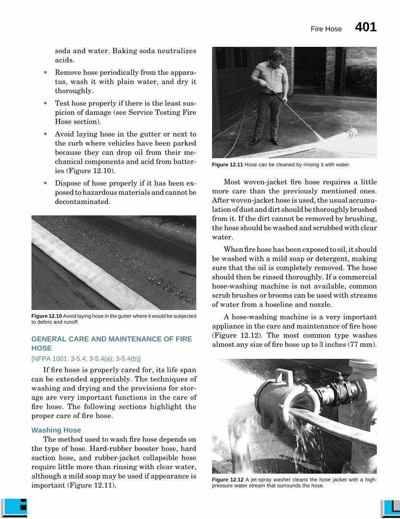
the type of hose. Hard-rubber booster hose, hardsuction hose, and rubber-jacket collapsible hoserequire little more than rinsing with clear water,although a mild soap may be used if appearance isimportant (Figure 12.11).
Figure 12.11 Hose can be cleaned by rinsing it with water.
Most woven-jacket fire hose requires a littlemore care than the previously mentioned ones.After woven-jacket hose is used, the usual accumu-lation of dust and dirt should be thoroughly brushedfrom it. If the dirt cannot be removed by brushing,the hose should be washed and scrubbed with clearwater.
When fire hose has been exposed to oil, it shouldbe washed with a mild soap or detergent, makingsure that the oil is completely removed. The hoseshould then be rinsed thoroughly. If a commercialhose-washing machine is not available, commonscrub brushes or brooms can be used with streamsof water from a hoseline and nozzle.
A hose-washing machine is a very importantappliance in the care and maintenance of fire hose(Figure 12.12). The most common type washesalmost any size of fire hose up to 3 inches (77 mm).
Figure 12.12 A jet-spray washer cleans the hose jacket with a high-pressure water stream that surrounds the hose.
402 ESSENTIALS
The flow of water into this device can be adjusted asdesired, and the movement of the water assists inpropelling the hose through the device. The hoselinethat supplies the washer with water can be con-nected to a pumper or used directly from a hydrant.Higher water pressure, obviously, gives better re-sults.
A cabinet-type machine that washes, rinses,and drains fire hose is designed to be used in thestation (Figure 12.13). This type of machine canbe operated by one person, is self-propelled, andcan be used with or without detergents.
Figure 12.13 A commercially produced hose-washing machine. Courtesyof Circul-Air Corporation.
Drying HoseThe methods used to dry hose depend on the
type of hose. Hard-rubber booster hose, hardsuction hose, and rubber-jacket collapsible hosemay be placed back on the apparatus while wetwith no ill effects. Woven-jacket hose requiresthorough drying before being reloaded on theapparatus. Hose should be dried in accordancewith local procedures and manufacturer’s rec-ommendations.
Storing HoseAfter fire hose has been adequately brushed,
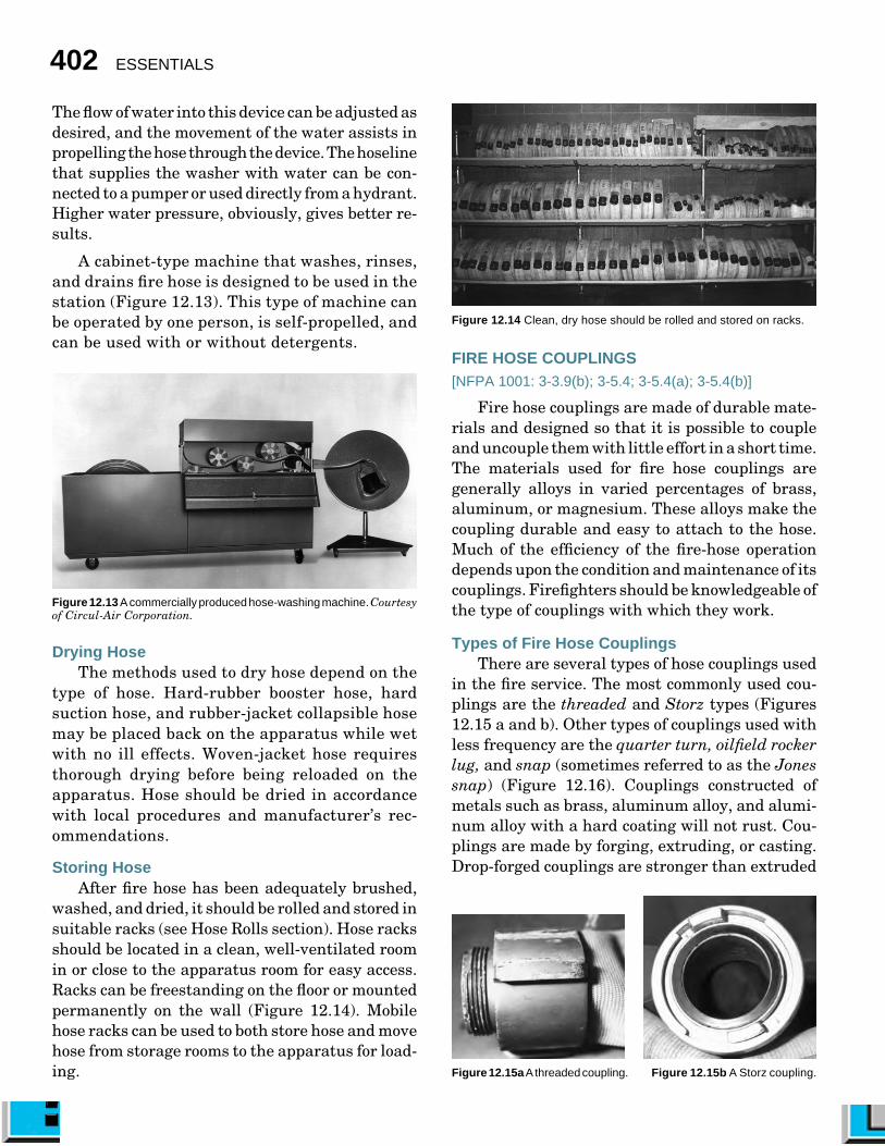
washed, and dried, it should be rolled and stored insuitable racks (see Hose Rolls section). Hose racksshould be located in a clean, well-ventilated roomin or close to the apparatus room for easy access.Racks can be freestanding on the floor or mountedpermanently on the wall (Figure 12.14). Mobilehose racks can be used to both store hose and movehose from storage rooms to the apparatus for load-ing.
Figure 12.14 Clean, dry hose should be rolled and stored on racks.
FIRE HOSE COUPLINGS[NFPA 1001: 3-3.9(b); 3-5.4; 3-5.4(a); 3-5.4(b)]
Fire hose couplings are made of durable mate-rials and designed so that it is possible to coupleand uncouple them with little effort in a short time.The materials used for fire hose couplings aregenerally alloys in varied percentages of brass,aluminum, or magnesium. These alloys make thecoupling durable and easy to attach to the hose.Much of the efficiency of the fire-hose operationdepends upon the condition and maintenance of itscouplings. Firefighters should be knowledgeable ofthe type of couplings with which they work.
Types of Fire Hose CouplingsThere are several types of hose couplings used
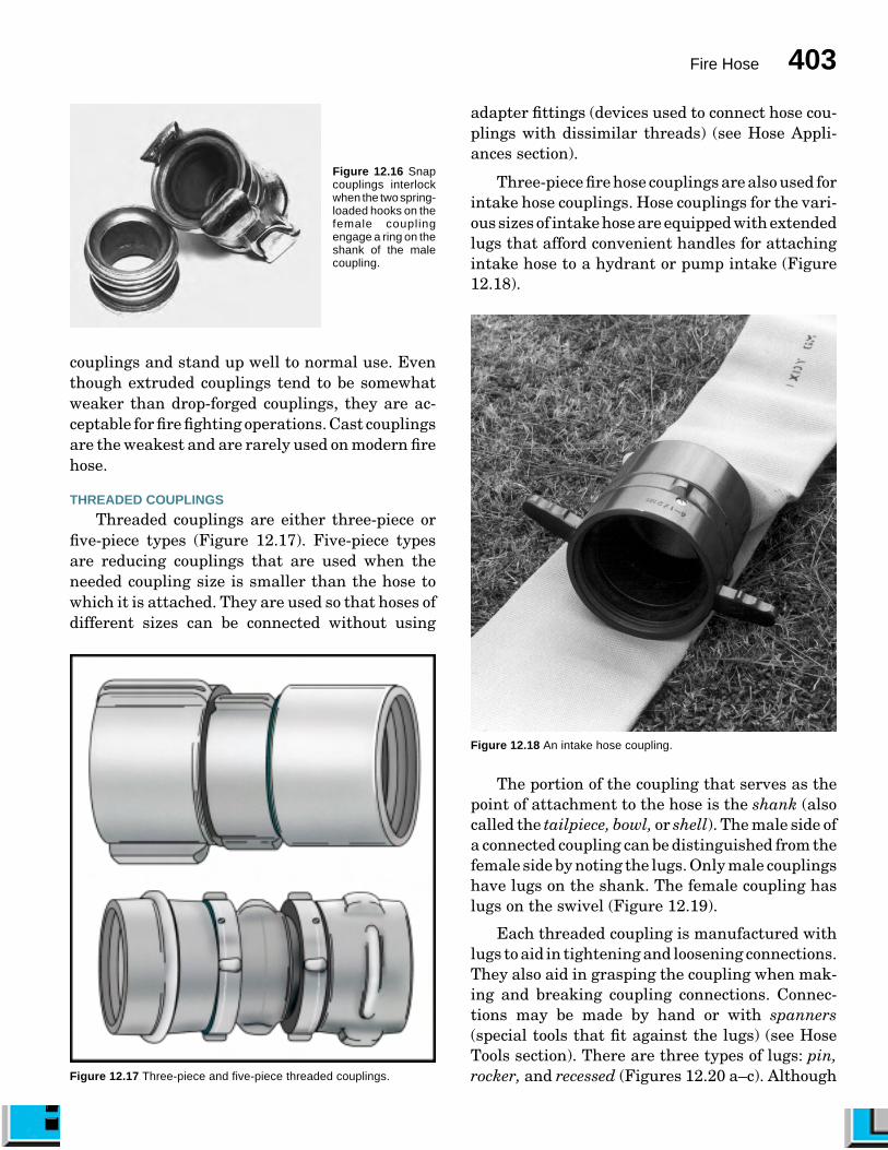
in the fire service. The most commonly used cou-plings are the threaded and Storz types (Figures12.15 a and b). Other types of couplings used withless frequency are the quarter turn, oilfield rockerlug, and snap (sometimes referred to as the Jonessnap) (Figure 12.16). Couplings constructed ofmetals such as brass, aluminum alloy, and alumi-num alloy with a hard coating will not rust. Cou-plings are made by forging, extruding, or casting.Drop-forged couplings are stronger than extruded
Figure 12.15b A Storz coupling.Figure 12.15a A threaded coupling.
Fire Hose 403
couplings and stand up well to normal use. Eventhough extruded couplings tend to be somewhatweaker than drop-forged couplings, they are ac-ceptable for fire fighting operations. Cast couplingsare the weakest and are rarely used on modern firehose.
THREADED COUPLINGS
Threaded couplings are either three-piece orfive-piece types (Figure 12.17). Five-piece typesare reducing couplings that are used when theneeded coupling size is smaller than the hose towhich it is attached. They are used so that hoses ofdifferent sizes can be connected without using
Figure 12.16 Snapcouplings interlockwhen the two spring-loaded hooks on thefemale couplingengage a ring on theshank of the malecoupling.
Figure 12.17 Three-piece and five-piece threaded couplings.
adapter fittings (devices used to connect hose cou-plings with dissimilar threads) (see Hose Appli-ances section).
Three-piece fire hose couplings are also used forintake hose couplings. Hose couplings for the vari-ous sizes of intake hose are equipped with extendedlugs that afford convenient handles for attachingintake hose to a hydrant or pump intake (Figure12.18).
Figure 12.18 An intake hose coupling.
The portion of the coupling that serves as thepoint of attachment to the hose is the shank (alsocalled the tailpiece, bowl, or shell). The male side ofa connected coupling can be distinguished from thefemale side by noting the lugs. Only male couplingshave lugs on the shank. The female coupling haslugs on the swivel (Figure 12.19).
Each threaded coupling is manufactured withlugs to aid in tightening and loosening connections.They also aid in grasping the coupling when mak-ing and breaking coupling connections. Connec-tions may be made by hand or with spanners(special tools that fit against the lugs) (see HoseTools section). There are three types of lugs: pin,rocker, and recessed (Figures 12.20 a–c). Although

404 ESSENTIALS
still available, pin-lug couplings are not commonlyordered with new fire hose because of their ten-dency to snag when hose is dragged over objects.Booster hose normally has couplings with recessedlugs, which are simply shallow holes drilled intothe coupling. This lug design prevents abrasionthat would occur if the hose had protruding lugsand was wound onto reels. These holes are de-signed to accept a special spanner wrench that canbe used to couple or uncouple the hose (Figure12.21). Modern threaded couplings have roundedrocker lugs. Most hose purchased today comesequipped with rocker lugs to help the coupling slideover obstructions when the hose is moved on theground or around objects. Hose couplings may beobtained with either two or three rocker lugs.
An added feature that may be obtained withscrew thread couplings is the Higbee cut and indi-cator. The Higbee cut is a special type of thread
Figure 12.19 The male side of a connected coupling can be distinguished from the female side by noting the rocker lugs on the shank.
Figure 12.20a Pin lug.
Figure 12.20b Rocker lugs.
Figure 12.20cRecessed lug.
Figure 12.21 This special spanner wrench is used to couple or uncouplehose with recessed lug couplings.
Fire Hose 405
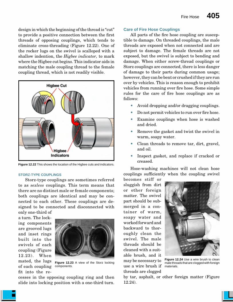
design in which the beginning of the thread is “cut”to provide a positive connection between the firstthreads of opposing couplings, which tends toeliminate cross-threading (Figure 12.22). One ofthe rocker lugs on the swivel is scalloped with ashallow indention, the Higbee indicator, to markwhere the Higbee cut begins. This indicator aids inmatching the male coupling thread to the femalecoupling thread, which is not readily visible.
Figure 12.22 This shows the location of the Higbee cuts and indicators.
STORZ-TYPE COUPLINGS
Storz-type couplings are sometimes referredto as sexless couplings. This term means thatthere are no distinct male or female components;both couplings are identical and may be con-nected to each other. These couplings are de-signed to be connected and disconnected withonly one-third ofa turn. The lock-ing componentsare grooved lugsand inset ringsbuilt into theswivels of eachcoupling (Figure12.23). Whenmated, the lugsof each couplingfit into the re-cesses in the opposing coupling ring and thenslide into locking position with a one-third turn.
Care of Fire Hose CouplingsAll parts of the fire hose coupling are suscep-
tible to damage. On threaded couplings, the malethreads are exposed when not connected and aresubject to damage. The female threads are notexposed, but the swivel is subject to bending anddamage. When either screw-thread couplings orStorz couplings are connected, there is less dangerof damage to their parts during common usage;however, they can be bent or crushed if they are runover by vehicles. This is reason enough to prohibitvehicles from running over fire hose. Some simplerules for the care of fire hose couplings are asfollows:
• Avoid dropping and/or dragging couplings.
• Do not permit vehicles to run over fire hose.
• Examine couplings when hose is washedand dried.
• Remove the gasket and twist the swivel inwarm, soapy water.
• Clean threads to remove tar, dirt, gravel,and oil.
• Inspect gasket, and replace if cracked orcreased.
Hose-washing machines will not clean hosecouplings sufficiently when the coupling swivelbecomes stiff orsluggish from dirtor other foreignmatter. The swivelpart should be sub-merged in a con-tainer of warm,soapy water andworked forward andbackward to thor-oughly clean theswivel. The malethreads should becleaned with a suit-able brush, and itmay be necessary touse a wire brush ifthreads are cloggedby tar, asphalt, or other foreign matter (Figure12.24).
Figure 12.23 A view of the Storz lockingcomponents.
Figure 12.24 Use a wire brush to cleanmale threads that are clogged with foreignmaterials.

406 ESSENTIALS
The swivelgasket and the ex-pansion-ring gas-ket are two typesof gaskets usedwith fire hose cou-plings. The swivelgasket is used tomake the connec-tion watertightwhen female andmale ends areconnected (Fig-ure 12.25). The expansion-ring gasket is used atthe end of the hose where it is expanded into theshank of the coupling. These two gaskets are notinterchangeable. The difference lies between theirthickness and width. Swivel gaskets should oc-casionally be removed from the coupling andchecked for cracks, creases, and general elasticdeterioration. The gasket inspection can be madeby simply pinching the gasket together betweenthe thumb and index finger. This method usuallydiscloses any defects and demonstrates the in-ability of the gasket to return to normal shape.Skill Sheet 12-1 shows the procedure for replac-ing the swivel gasket.
HOSE APPLIANCES AND HOSE TOOLS[NFPA 1001: 4-3.2(a)]
A complete hose layout for fire fighting pur-poses includes one end of the hose attached to orsubmerged in a source of water and the otherattached to a nozzle or similar discharge device.There are various devices used with fire hose,other than hose couplings and nozzles, to com-plete such an arrangement. These devices areusually grouped into two categories: hose appli-ances and hose tools. Appliances include valves,valve devices (such as wyes, siameses, waterthieves, large diameter hose appliances, andhydrant valves), fittings (which include adapt-ers), and intake devices. Examples of hose toolsinclude hose rollers, spanner wrenches, hosestrap and hose rope tools, hose chain tools, hoseramps, hose jackets, blocks, and hose clamps.The following sections highlight some of themore common hose appliances and hose tools.
Hose AppliancesA hose appliance is any piece of hardware used
in conjunction with fire hose for the purpose ofdelivering water. A simple way to remember thedifference between hose appliances and hose toolsis that appliances have water flowing throughthem and tools do not.
VALVES
The flow of water is controlled by various valvesin hoselines, at hydrants, and at pumpers. Thesevalves include the following types:
• Ball valves — Used in pumper dischargesand gated wyes (Figure 12.26). Ball valvesare open when the handle is in line with thehose and closed when it is at a right angle tothe hose. Ball valves are also used in firepump piping systems.
• Gate valves — Used to control the flowfrom a hydrant. Gate valves have a bafflethat is moved by a handle and screw ar-rangement (Figure 12.27).
• Butterfly valves — Used on large pumpintakes. A butterfly valve uses a flat baffleoperated by a quarter-turn handle. Thebaffle is in the center of the waterway whenthe valve is open (Figure 12.28).
• Clapper valves — Used in siamese appli-ances (see Valve Devices section) to allowonly one intake hose to be connected andcharged before the addition of more hoses.The clapper is a flat disk that is hinged onone side and swings in a door-like manner(Figure 12.29).
VALVE DEVICES
Valve devices increase or decrease the numberof hoselines operating at the fireground. Thesedevices include wye appliances, siamese appli-ances, water thief appliances, large diameter hoseappliances, and hydrant valves.
Wye appliances. Certain situations make itdesirable to divide a line of hose into two or morelines. Various types of wye connections are used forthis purpose. The most common wye has a 2¹�₂-inch(65 mm) inlet to two 1¹�₂-inch (38 mm) outlets,although there are many other combinations com-
Figure 12.25 A view of a swivel gasket inposition.
Fire Hose 407
Figure 12.26 A par-tially open (or closed)ball valve.
Figure 12.27 A cutaway of a gatevalve.
Figure 12.28 Abutterfly valve.
Figure 12.29 Aclapper valve insidea siamese appli-ance.
monly found (Figure 12.30). The 2¹�₂-inch (65 mm)wye is also used to divide one 2¹�₂-inch (65 mm) orlarger hoseline into two 2¹�₂-inch (65 mm) lines(Figure 12.31). Wye appliances are often gated sothat water being fed into the hoselines may becontrolled at the gate.
Figure 12.30 Thiscommon wye has a2¹�₂-inch (65 mm)inlet to two 1¹�₂-inch(38 mm) outlets. Itis often referred toas a “leader line”wye.
Figure 12.31 A2¹�₂-inch (65 mm)wye is used todivide one 2¹�₂-inch(65 mm) or largerhoseline into two2¹�₂-inch (65 mm)lines.
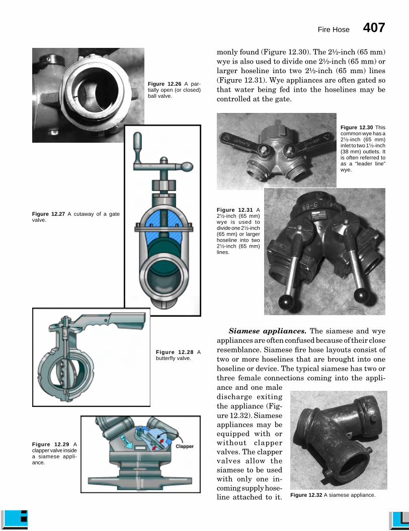
Siamese appliances. The siamese and wyeappliances are often confused because of their closeresemblance. Siamese fire hose layouts consist oftwo or more hoselines that are brought into onehoseline or device. The typical siamese has two orthree female connections coming into the appli-ance and one maledischarge exitingthe appliance (Fig-ure 12.32). Siameseappliances may beequipped with orwithout clappervalves. The clappervalves allow thesiamese to be usedwith only one in-coming supply hose-line attached to it. Figure 12.32 A siamese appliance.

408 ESSENTIALS
Siamese appliances are commonly used to over-come the problems caused by friction loss in hoselays that carry a large flow or cover a long distance.They are also used quite frequently when supply-ing ladder pipes that are not equipped with apermanent waterway. Two or three lines are usedto supply the one line that is actually going up theladder. With the increased popularity of largediameter hose (LDH), siamese appliances are be-ing used to feed a large diameter hoseline whenmultiple smaller hoselines have to be used in thesame relay as larger diameter hose.
Water thief appliances. The water thief is avariation of the wye appliance. The most commonwater thief consists of one 2¹�₂-inch (65 mm) inletwith one 2¹�₂-inch (65 mm) and two 1¹�₂-inch (38mm) discharge outlets, although other versions,such as a 1¹�₂-inch (38 mm) to 1-inch (25 mm) model,are in use (Figures 12.33 a and b). Quarter-turnvalves control the outlets. The water thief is in-tended to be used on a 2¹�₂-inch (65 mm) or largerhoseline, usually near the nozzle, so that 2¹�₂-inch(65 mm) and 1¹�₂-inch (38 mm) hoselines may beused as desired from the same layout.
Figure 12.33b Thisforestry water thiefis designed to splita 1-inch (25 mm)hose off the main1¹�₂-inch (38 mm)hose.
Figure 12.33aA water thiefappliance.
Large diameter hose appliances. Large di-ameter hose operations often necessitate the use ofspecial appliances to distribute the water near thefinal destination of the hoseline. Depending on thelocale and the brand of the appliance, these devicesare sometimes called portable hydrants, mani-folds, phantom pumpers, or large diameter dis-tributors. These appliances come in a variety offorms, but in general they have one 4- or 5-inch(100 mm or 125 mm) inlet and two or more smalleroutlets (Figure 12.34). Some are similar to waterthieves in that they contain one discharge that isthe same size as the intake along with severalsmaller discharges.
Figure 12.34 A manifolddistributes water to anumber of hoses.
Hydrant valves. A variety of hydrant valvesare available for use in supply-line operations(Figures 12.35 a and b). These valves are usedwhen a hose lay is made from the water-supplysource to the fire scene (forward or straight lay)(see Supply Hose Lays section). The hydrant valveallows the original supply line to be connected to
Figure 12.35a A four-wayhydrant valve.
Figure 12.35b A typicalhydrant valve. Courtesy ofGeorge Braun, Gainesville(FL) Fire-Rescue.

Fire Hose 409
the hydrant and charged before the arrival ofanother pumper at the hydrant. By using thehydrant valve, additional hoselines may be laid tothe hydrant, the supply pumper may connect to thehydrant, and pressure may be boosted in the origi-nal supply line without having to interrupt the flowof water in the original supply line (Figure 12.36).
Figure 12.36 Typical operation of a hydrant valve. Courtesy ofHarrington, Inc.
FITTINGS
Hardware accessories called fittings are avail-able for connecting hoses of different sizes andthread types (Figures 12.37 a–c). An adapter is afitting for connecting hose couplings with dis-similar threads but with the same inside diam-eter. A variety of special hose appliances aresometimes used in special situations. The double
male and double female adapters are probablyused more than any other special hose appliance.These appliances allow hoses to be connectedwhen both couplings are of the same sex. Thisneed most frequently occurs when a pumper thatis set up for a forward hose lay is used for areverse lay (laying hose from fire scene back towater supply source) or vice versa (see SupplyHose Lays section).
A reducer, another common hose fitting, is usedto extend a larger hoseline by connecting a smallerone to the end. Reducers are also commonly foundon pump discharge outlets so that smaller hoselinesmay be hooked directly to the pump. It should benoted that extending a line with a reducer limitsoptions to just that hoseline whereas using a gatedwye at that point allows the option of addinganother line if needed.
Figure 12.37a A doublefemale adapter.
Figure 12.37b A double maleadapter.
Figure 12.37c A reducer fitting.

410 ESSENTIALS
Other common fittings include elbows thatchange the direction of flow, hose caps that close offmale couplings, and hose plugs that close off femalecouplings (Figures 12.38 a–c).
Figure 12.38a Anelbow fitting changesthe direction of flow.
Figure 12.38b A cap is used toclose off male couplings or pumpdischarges.
Figure 12.38c A plug isused to close a femalecoupling or a pump intakeconnection.
INTAKE DEVICES
Suction hose strainers are intake devices at-tached to the drafting end of a hard suction (sleeve)to keep debris from entering the fire pump. Suchdebris can pass through the pump and down theline to plug the nozzle. Strainers should not beallowed to rest on the bottom of the water sourceexcept when the bottom is clean and hard, such asthe bottom of a swimming pool. In order to preventstrainers from resting on the bottom of the watersource, some are provided with an eyelet to whicha short length of rope can be attached. Some de-partments keep this rope attached to the straineras shown in Figure 12.39.
Hose ToolsThere are a variety of tools used in conjunction
with hoselines. The following sections highlightsome of the more common ones: hose rollers, span-ner wrenches, hose strap and hose rope tools, hosechain tools, hose clamps, hose jackets, ramps, andblocks. As stated earlier, hose tools do not havewater flowing through them.
HOSE ROLLER (HOIST)
Hose can be damaged when dragged over sharpsurfaces such as roof edges and windowsills. A toolfor preventing such damage is the hose roller (alsoknow as hose hoist) (Figure 12.40). The hose roller,consisting of a metal frame with two or morerollers, is placed on the potentially damaging edgeand secured with a rope or C-clamp. The hose isthen pulled over the rollers. This tool can also beused for handling rope over similar edges.
Figure 12.39 A rope attached to a strainer helps keep the strainer fromresting on the bottom of the water source.
Figure 12.40 A hose roller prevents hose from being damaged by beingdragged over rough or sharp edges.
HOSE JACKET
When a section of hose ruptures, the entirehoseline is unable to transport water effectively.The most practical way to permanently correct the

Fire Hose 411
problem is to shut down the line and replace thedamaged section of hose. When fire fighting con-ditions are such that it is not possible to shutdown the hoseline and replace the bad section, ahose jacket can be installed on the hose at thepoint of rupture. A hose jacket consists of a two-piece metal cylinder that hinges open and closed(Figure 12.41). Rubber gaskets at each end of thecylinder seal against the hose to prevent leak-age. A clamp device locks the cylinder closedwhen in use. Hose jackets are made in two sizes:2¹�₂ inches and 3 inches (65 mm and 77 mm). Thehose jacket encloses the hose so effectively that itcan continue to operate at full pressure. A hosejacket can also be used to connect hose withmismatched or damaged screw-thread couplings.
Figure 12.41 A hose jacket in use.
HOSE CLAMP
A hose clamp can be used to stop the flow ofwater in a hoseline for the following reasons:
• To prevent charging the hose bed duringhose-lay operations
• To allow replacement of a burst section ofhose without shutting down the water sup-ply (see Replacing Burst Sections section)
• To allow extension of a hoseline withoutshutting down the water supply (see Ex-tending a Section of Hose section)
• To allow advancement of a charged hoselineup stairs (see Advancing Hose Up a Stair-way section)
Based on the method by which they work, thereare three types of hose clamps: screw-down, press-down, and hydraulic press (Figure 12.42). It isimportant to know that a hose clamp can causeinjury to firefighters or damage hose if it is not usedcorrectly. Some general rules that apply to hoseclamps are as follows:
• Apply the hose clamp at least 20 feet (6 m)behind the apparatus (Figure 12.43).
• Apply the hose clamp approximately 5 feet(1.5 m) from the coupling on the incomingwater side.
• Stand to one side when applying or releas-ing the press-down type of hose clamp (theoperating handle is prone to snapping opensuddenly) (Figure 12.44).
CAUTION: Never stand over the handle of ahose clamp when applying or releasing it. Thehandle may swing upward in a violent motion andinjure the firefighter attempting to operate thehandle.
Figure 12.42 Various types of hose clamps.
Figure 12.43 Place the hose clamp at least 20 feet (6 m) behind theapparatus and approximately 5 feet (1.5 m) behind the coupling.

412 ESSENTIALS
• Center the hose evenly in the jaws to avoidpinching the hose.
• Close and open the hose clamp slowly toavoid water hammer.
Figure 12.44 Always stand to one side when applying or releasing thepress-down type of hose clamp.
SPANNER, HYDRANT WRENCH, AND RUBBER MALLET
The primary purpose of a spanner wrench, orsimply spanner, is to tighten and loosen hosecouplings (Figure 12.45). A number of other fea-tures have been built into some spannerwrenches:
• Wedge for prying
• Opening that fits gas utility valves
• Slot for pulling nails
• Flat surface for hammering
Hydrant wrenches are primarily used to re-move caps from fire hydrant outlets and to open firehydrant valves. The hydrant wrench is usuallyequipped with a pentagon opening in its head thatfits most standard fire hydrant operating nuts. Thelever handle may be threaded into the operatinghead to make it adjustable, or the head and handlemay be of the ratchet type. The head may also beequipped with a spanner to help make or breakcoupling connections.
Figure 12.45 Various types of hand tools used in hose operations.
The rubber mallet is used to strike the lugs totighten or loosen intake hose couplings. It is some-times difficult to get a completely airtight connec-tion with intake hose couplings even though thesecouplings may be equipped with long operatinglugs. Thus, the rubber mallet is used to furthertighten the connection.
HOSE BRIDGE OR RAMP
Hose bridges (also called hose ramps) help pre-vent injury to hose when vehicles cross it (Figure12.46). They should be used wherever a hoselinecrosses a street or other area where vehicular trafficcannot be diverted. Some ramps can also be posi-
Figure 12.46 Various types of hose bridges (ramps).

Fire Hose 413
tioned over small spills to keep hoselines out ofpotentially damaging liquids. Hose ramps can also beused as chafing blocks (device used to prevent hosefrom rubbing against the ground or concrete pave-ment). See following Chafing Block section.
CHAFING BLOCK
Chafing blocks are devices that are used to pro-tect fire hose where the hose is subjected to rubbingfrom vibrations (Figure 12.47). Chafing blocks areparticularly useful where intake hose comes in con-tact with pavement or curb steps. At these points,wear on intake hose is most likely because pumpervibrations may be keeping the intake hose in con-stant motion. Chafing blocks may be made of wood,leather, or sections of old truck tires.
HOSE STRAP, HOSE ROPE, AND HOSE CHAIN
One of the most useful tools to aid in carryingor handling a charged hoseline is a hose strap.Similar to the hose strap are the hose rope andhose chain. These devices can be used to carryand pull fire hose, but their primary value is toprovide a more secure means to handle pressur-ized hose when applying water. Another impor-tant use of these tools is to secure hose to laddersand other fixed objects (Figures 12.48 a and b).
HOSE ROLLS
[NFPA 1001: 3-5.4; 3-5.4(a); 3-5.4(b)]
There are a number of different methods forrolling fire hose, depending on its intended use.
Figure 12.47 Chafing blocks prevent damage to intake hose.
Figure 12.48a Typical hose tools.Figure 12.48b Attach a hose strap or rope tool so that the nozzle is withineasy reach.

414 ESSENTIALS
In all methods, care must be taken to protect thecouplings. Some of the various hose rolls will bediscussed in the following sections.
Straight RollThe straight roll consists of starting at one
end, usually at the male coupling, and rolling thehose toward the other end to complete the roll(Figure 12.49). When the roll is completed, thefemale end is exposed and the male end is pro-tected in the center of the roll. The straight rollis commonly used for hose in the following situ-ations:
• When loaded back on the apparatus at thefire scene
• When returned to quarters for washing
• When placed in storage (especially rackstorage)
Figure 12.49 A straight roll.
This method is also used for easy loading ofthe minuteman load (See Preconnected HoseLoads For Attack Lines section).
A variation of the straight roll is to begin theroll at the female coupling so that when the rollis completed, the male coupling is exposed. Thismethod is often done to denote a damaged cou-pling or piece of hose. A tag is usually attached tothe male coupling indicating the type and loca-tion of damage. This is also done when the hoseis going to be reloaded on the apparatus for aforward (straight) lay. Skill Sheet 12-2 describesthe procedure for making the basic straight roll.
Donut RollThe donut roll is commonly used in situations
where hose is going to be deployed for use di-rectly from a roll (Figure 12.50). The donut rollhas certain advantages that the straight rolldoes not possess. Three main advantages arethat both ends are available on the outside of theroll, the hose may be quickly unrolled and placedinto service, and the hose is less likely to spiral orkink when unrolled. When a section of fire hoseneeds to be rolled into a donut roll, one or twofirefighters may perform the task. Skill Sheets12-3 and 12-4 describe two methods used to makethe donut roll.
Figure 12.50 A donut roll.
Twin Donut RollThe twin donut roll is more adaptable to 1¹�₂-
inch (38 mm) and 1³�₄-inch (45 mm) hose, al-though 2-, 2¹�₂-, or 3-inch (50 mm, 65 mm, or 77mm) hose can be used (Figure 12.51). Its purposeis to arrange a compact roll that may be trans-ported and carried for special applications suchas high-rise operations. Skill Sheet 12-5 describeshow the twin donut roll can be made.
If the couplings are offset by about 1 foot (0.3m) at the beginning, they can be coupled togetherafter the roll is tied or strapped. This forms aconvenient loop that can be slung over one shoul-der for carrying while leaving the hands free. Byoffsetting the couplings at the beginning, they donot dig into the shoulder but are still readilyaccessible when needed to place the section inservice (Figure 12.52).

Fire Hose 415
Figure 12.51 A twin donut roll.
Figure 12.52 If the couplings are offset by about 1 foot (0.3 m) at thebeginning, they can be coupled together after the roll is tied or strapped.
Self-Locking Twin Donut RollThe self-locking twin donut roll is a twin
donut roll that has a built-in carrying strapformed from the hose itself (Figure 12.53). Thisstrap locks over the couplings to keep the rollintact for carrying. The length of the carryingstrap may be adjusted to accommodate the height
of the person carry-ing the hose. SkillSheet 12-6 describeshow to make the self-locking twin donutroll.
Figure 12.53 A self-lockingtwin donut roll.
COUPLING ANDUNCOUPLING FIREHOSE[NFPA 1001: 3-3.9(b)]
The processes ofcoupling and uncou-pling hose are, for themost part, simple pro-cedures for fasteningand separating themale and female hosecouplings or the sex-less couplings in thecase of the Storz-type couplings. The need for speedand accuracy under emergency conditions requiresthat specific techniques for coupling and uncou-pling hose be developed. Nozzles may be attachedto the hose and separated from the hose by usingthe same methods as when coupling and uncou-pling two sections of hose.
Skill Sheets 12-7 and 12-8 describe two meth-ods of coupling threaded couplings; the same tech-niques can be applied to Storz (sexless) couplings.It is sometimes necessary to break a tight couplingwhen spanner wrenches are not available. SkillSheets 12-9 and 12-10 show two methods by whichone or two firefighters may accomplish this task.
BASIC HOSE LOADS AND FINISHES[NFPA 1001: 3-5.4; 3-5.4(a); 3-5.4(b)]
The most common terminology used to describea fire hose compartment is hose bed. Hose beds varyin size and shape, and they are sometimes built forspecific needs. In this manual, the front of the hosebed is designated as that part of the compartmenttoward the front of the apparatus, and the rear of
416 ESSENTIALS
the hose bed is designated as that part of thecompartment toward the rear of the apparatus.Most hose beds have open slats in the bottom thatenable air to circulate throughout the hose load.Without this feature, woven-jacket hose could mil-dew and rot in a very short time.
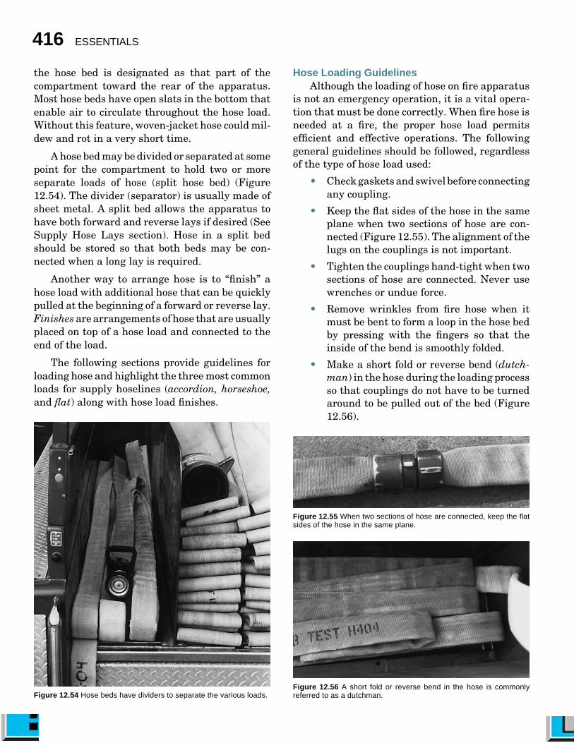
A hose bed may be divided or separated at somepoint for the compartment to hold two or moreseparate loads of hose (split hose bed) (Figure12.54). The divider (separator) is usually made ofsheet metal. A split bed allows the apparatus tohave both forward and reverse lays if desired (SeeSupply Hose Lays section). Hose in a split bedshould be stored so that both beds may be con-nected when a long lay is required.
Another way to arrange hose is to “finish” ahose load with additional hose that can be quicklypulled at the beginning of a forward or reverse lay.Finishes are arrangements of hose that are usuallyplaced on top of a hose load and connected to theend of the load.
The following sections provide guidelines forloading hose and highlight the three most commonloads for supply hoselines (accordion, horseshoe,and flat) along with hose load finishes.
Figure 12.54 Hose beds have dividers to separate the various loads.
Hose Loading GuidelinesAlthough the loading of hose on fire apparatus
is not an emergency operation, it is a vital opera-tion that must be done correctly. When fire hose isneeded at a fire, the proper hose load permitsefficient and effective operations. The followinggeneral guidelines should be followed, regardlessof the type of hose load used:
• Check gaskets and swivel before connectingany coupling.
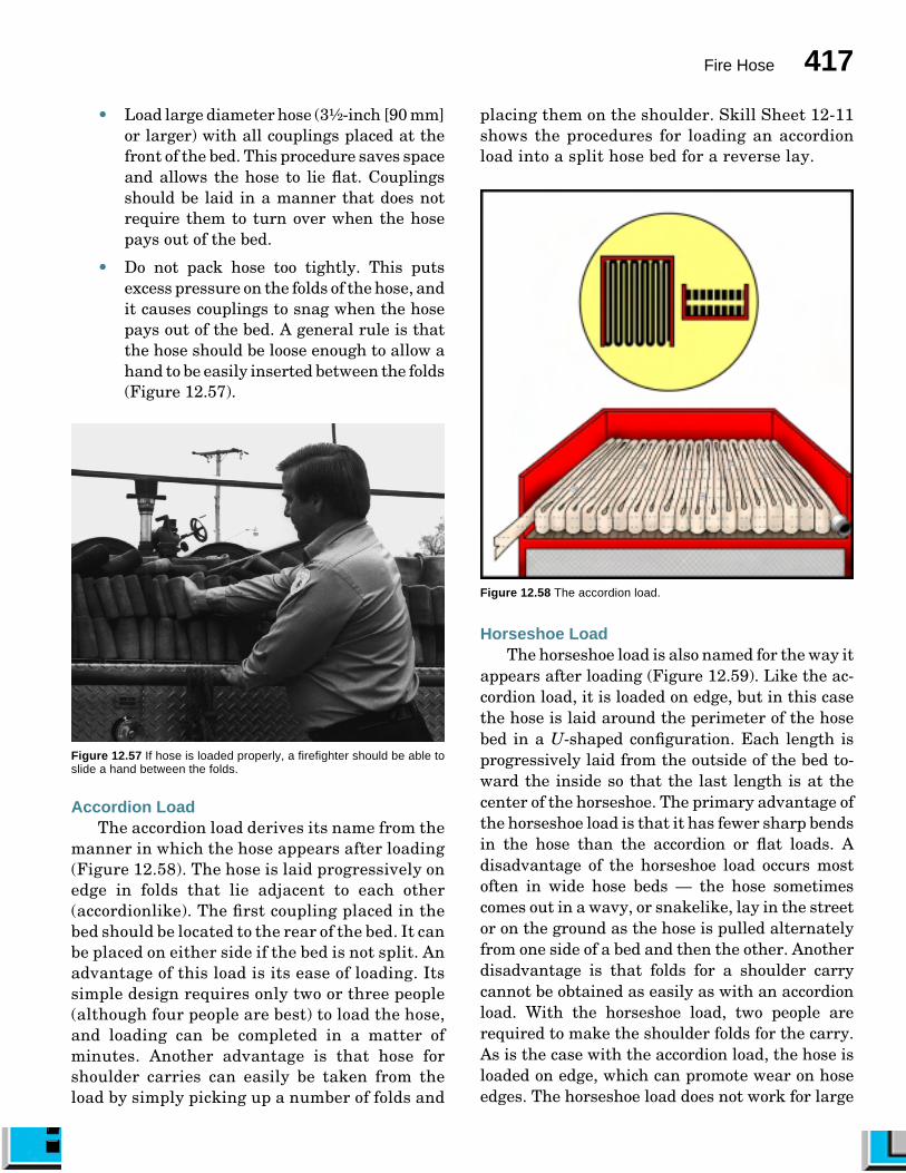
• Keep the flat sides of the hose in the sameplane when two sections of hose are con-nected (Figure 12.55). The alignment of thelugs on the couplings is not important.
• Tighten the couplings hand-tight when twosections of hose are connected. Never usewrenches or undue force.
• Remove wrinkles from fire hose when itmust be bent to form a loop in the hose bedby pressing with the fingers so that theinside of the bend is smoothly folded.
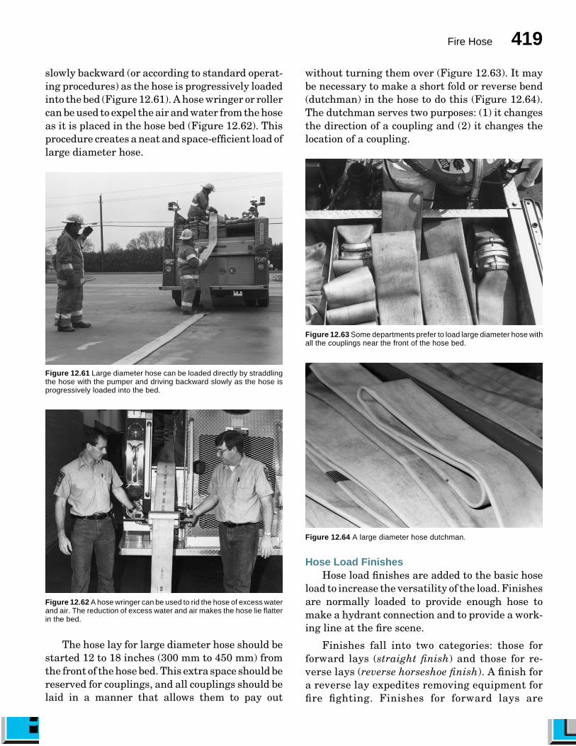
• Make a short fold or reverse bend (dutch-man) in the hose during the loading processso that couplings do not have to be turnedaround to be pulled out of the bed (Figure12.56).
Figure 12.55 When two sections of hose are connected, keep the flatsides of the hose in the same plane.
Figure 12.56 A short fold or reverse bend in the hose is commonlyreferred to as a dutchman.
Fire Hose 417
• Load large diameter hose (3¹�₂-inch [90 mm]or larger) with all couplings placed at thefront of the bed. This procedure saves spaceand allows the hose to lie flat. Couplingsshould be laid in a manner that does notrequire them to turn over when the hosepays out of the bed.
• Do not pack hose too tightly. This putsexcess pressure on the folds of the hose, andit causes couplings to snag when the hosepays out of the bed. A general rule is thatthe hose should be loose enough to allow ahand to be easily inserted between the folds(Figure 12.57).
Figure 12.57 If hose is loaded properly, a firefighter should be able toslide a hand between the folds.
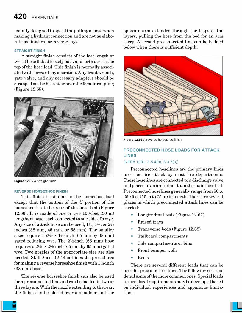
Accordion LoadThe accordion load derives its name from the
manner in which the hose appears after loading(Figure 12.58). The hose is laid progressively onedge in folds that lie adjacent to each other(accordionlike). The first coupling placed in thebed should be located to the rear of the bed. It canbe placed on either side if the bed is not split. Anadvantage of this load is its ease of loading. Itssimple design requires only two or three people(although four people are best) to load the hose,and loading can be completed in a matter ofminutes. Another advantage is that hose forshoulder carries can easily be taken from theload by simply picking up a number of folds and
placing them on the shoulder. Skill Sheet 12-11shows the procedures for loading an accordionload into a split hose bed for a reverse lay.
Figure 12.58 The accordion load.
Horseshoe LoadThe horseshoe load is also named for the way it
appears after loading (Figure 12.59). Like the ac-cordion load, it is loaded on edge, but in this casethe hose is laid around the perimeter of the hosebed in a U-shaped configuration. Each length isprogressively laid from the outside of the bed to-ward the inside so that the last length is at thecenter of the horseshoe. The primary advantage ofthe horseshoe load is that it has fewer sharp bendsin the hose than the accordion or flat loads. Adisadvantage of the horseshoe load occurs mostoften in wide hose beds — the hose sometimescomes out in a wavy, or snakelike, lay in the streetor on the ground as the hose is pulled alternatelyfrom one side of a bed and then the other. Anotherdisadvantage is that folds for a shoulder carrycannot be obtained as easily as with an accordionload. With the horseshoe load, two people arerequired to make the shoulder folds for the carry.As is the case with the accordion load, the hose isloaded on edge, which can promote wear on hoseedges. The horseshoe load does not work for large

418 ESSENTIALS
diameter hose because the hose remaining in thebed tends to fall over as the hose pays off, whichcauses the hose to become entangled.
In a single hose bed, the horseshoe load may bestarted on either side. In a split hose bed, lay thefirst length against the partition with the couplinghanging an appropriate distance below the hosebed. Determine this distance by estimating theanticipated height of the completed hose load sothat the coupling can be connected to the lastcoupling of the load on the opposite side (crossover)and laid on top of the load. This placement allowseasy disconnection of the couplings when the loadmust be split to lay dual lines. When one side isloaded for a reverse lay and the other is loaded fora forward lay (combination load), use an adapter toconnect identical couplings. Skill Sheet 12-12 de-scribes the procedures for a single-bed horseshoeload set up for a reverse lay.
Flat LoadOf the three supply hose loads, the flat load is
the easiest to load. It is suitable for any size ofsupply hose and is the best way to load largediameter hose. As the name implies, the hose islaid so that its folds lie flat rather than on edge
Figure 12.59 The horseshoe load.
(Figure 12.60). Hose loaded in this manner is lesssubject to wear from apparatus vibration duringtravel. A disadvantage of this load is that the hosefolds contain sharp bends at both ends, whichrequires that the hose be reloaded periodically torelocate bends within each length to prevent dam-age to the lining.
In a single hose bed, the flat load may be startedon either side. In a split hose bed, lay the firstlength against the partition with the couplinghanging an appropriate distance below the hosebed. Determine this distance by estimating theanticipated height of the hose bed so that thecoupling can be connected to the last coupling of theload on the opposite side (crossover) and laid on topof the load. This placement allows easy disconnec-tion of the couplings when the load must be split tolay dual lines. With a combination load, use anadapter to connect identical couplings. Skill Sheet12-13 shows the procedures for loading a split-bedcombination flat load.
Figure 12.60 The flat load in a split hose bed.
The flat load method described in Skill Sheet12-13 can be adapted for loading large diameterhose. Large diameter hose can be loaded directlyfrom the street or ground after an incident bystraddling the hose with the pumper and driving
Fire Hose 419
slowly backward (or according to standard operat-ing procedures) as the hose is progressively loadedinto the bed (Figure 12.61). A hose wringer or rollercan be used to expel the air and water from the hoseas it is placed in the hose bed (Figure 12.62). Thisprocedure creates a neat and space-efficient load oflarge diameter hose.
Figure 12.61 Large diameter hose can be loaded directly by straddlingthe hose with the pumper and driving backward slowly as the hose isprogressively loaded into the bed.
Figure 12.62 A hose wringer can be used to rid the hose of excess waterand air. The reduction of excess water and air makes the hose lie flatterin the bed.
The hose lay for large diameter hose should bestarted 12 to 18 inches (300 mm to 450 mm) fromthe front of the hose bed. This extra space should bereserved for couplings, and all couplings should belaid in a manner that allows them to pay out
without turning them over (Figure 12.63). It maybe necessary to make a short fold or reverse bend(dutchman) in the hose to do this (Figure 12.64).The dutchman serves two purposes: (1) it changesthe direction of a coupling and (2) it changes thelocation of a coupling.
Figure 12.63 Some departments prefer to load large diameter hose withall the couplings near the front of the hose bed.
Figure 12.64 A large diameter hose dutchman.
Hose Load FinishesHose load finishes are added to the basic hose
load to increase the versatility of the load. Finishesare normally loaded to provide enough hose tomake a hydrant connection and to provide a work-ing line at the fire scene.
Finishes fall into two categories: those forforward lays (straight finish) and those for re-verse lays (reverse horseshoe finish). A finish fora reverse lay expedites removing equipment forfire fighting. Finishes for forward lays are
420 ESSENTIALS
usually designed to speed the pulling of hose whenmaking a hydrant connection and are not as elabo-rate as finishes for reverse lays.
STRAIGHT FINISH
A straight finish consists of the last length ortwo of hose flaked loosely back and forth across thetop of the hose load. This finish is normally associ-ated with forward-lay operation. A hydrant wrench,gate valve, and any necessary adapters should bestrapped on the hose at or near the female coupling(Figure 12.65).
Figure 12.65 A straight finish.
REVERSE HORSESHOE FINISH
This finish is similar to the horseshoe loadexcept that the bottom of the U portion of thehorseshoe is at the rear of the hose bed (Figure12.66). It is made of one or two 100-foot (30 m)lengths of hose, each connected to one side of a wye.Any size of attack hose can be used, 1¹�₂, 1³�₄, or 2¹�₂
inches (38 mm, 45 mm, or 65 mm). The smallersizes require a 2¹�₂- × 1¹�₂-inch (65 mm by 38 mm)gated reducing wye. The 2¹�₂-inch (65 mm) hoserequires a 2¹�₂- × 2¹�₂-inch (65 mm by 65 mm) gatedwye. Two nozzles of the appropriate size are alsoneeded. Skill Sheet 12-14 outlines the proceduresfor making a reverse horseshoe finish with 1¹�₂-inch(38 mm) hose.
The reverse horseshoe finish can also be usedfor a preconnected line and can be loaded in two orthree layers. With the nozzle extending to the rear,the finish can be placed over a shoulder and the
opposite arm extended through the loops of thelayers, pulling the hose from the bed for an armcarry. A second preconnected line can be beddedbelow when there is sufficient depth.
Figure 12.66 A reverse horseshoe finish.
PRECONNECTED HOSE LOADS FOR ATTACKLINES[NFPA 1001: 3-5.4(b); 3-3.7(a)]
Preconnected hoselines are the primary linesused for fire attack by most fire departments.These hoselines are connected to a discharge valveand placed in an area other than the main hose bed.Preconnected hoselines generally range from 50 to250 feet (15 m to 75 m) in length. There are severalplaces in which preconnected attack lines can becarried:
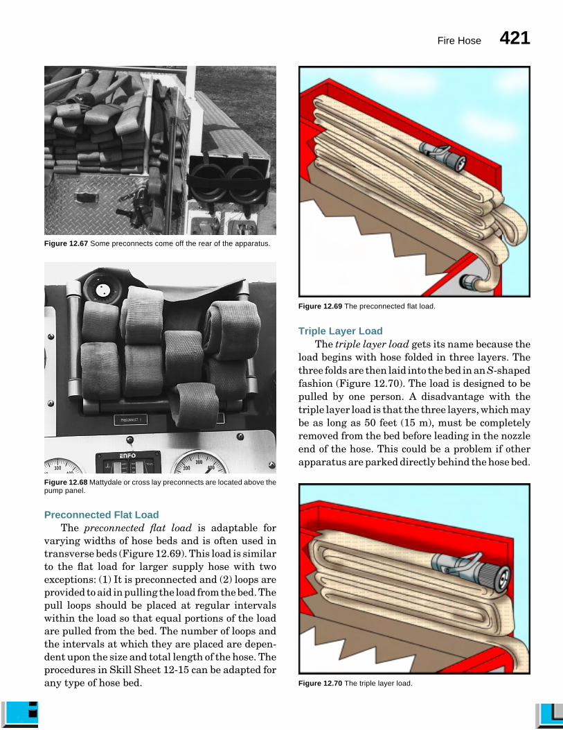
• Longitudinal beds (Figure 12.67)
• Raised trays
• Transverse beds (Figure 12.68)
• Tailboard compartments
• Side compartments or bins
• Front bumper wells
• Reels
There are several different loads that can beused for preconnected lines. The following sectionsdetail some of the more common ones. Special loadsto meet local requirements may be developed basedon individual experiences and apparatus limita-tions.
Fire Hose 421
Figure 12.68 Mattydale or cross lay preconnects are located above thepump panel.
Figure 12.67 Some preconnects come off the rear of the apparatus.
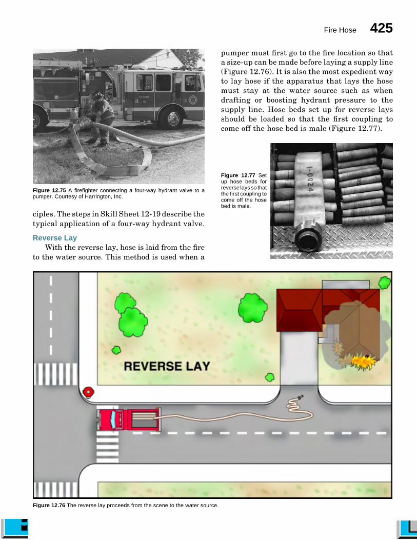
Preconnected Flat LoadThe preconnected flat load is adaptable for
varying widths of hose beds and is often used intransverse beds (Figure 12.69). This load is similarto the flat load for larger supply hose with twoexceptions: (1) It is preconnected and (2) loops areprovided to aid in pulling the load from the bed. Thepull loops should be placed at regular intervalswithin the load so that equal portions of the loadare pulled from the bed. The number of loops andthe intervals at which they are placed are depen-dent upon the size and total length of the hose. Theprocedures in Skill Sheet 12-15 can be adapted forany type of hose bed.
Figure 12.69 The preconnected flat load.
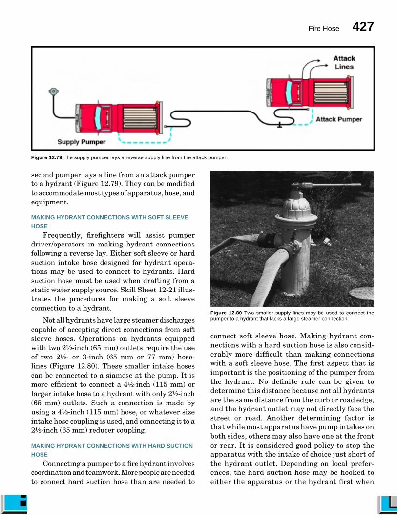
Triple Layer LoadThe triple layer load gets its name because the
load begins with hose folded in three layers. Thethree folds are then laid into the bed in an S-shapedfashion (Figure 12.70). The load is designed to bepulled by one person. A disadvantage with thetriple layer load is that the three layers, which maybe as long as 50 feet (15 m), must be completelyremoved from the bed before leading in the nozzleend of the hose. This could be a problem if otherapparatus are parked directly behind the hose bed.
Figure 12.70 The triple layer load.

422 ESSENTIALS
While this hose load can be used for all sizes ofattack lines, it is often preferred for larger (2- and2¹�₂-inch [50 and 65 mm]) lines that may be toocumbersome for shoulder carries. The proceduresfor making the triple layer load for 200 feet (60 m)of 1¹�₂- or 1³⁄₄-inch (38 mm or 45 mm) hose are givenin Skill Sheet 12-16.
Minuteman LoadThe minuteman load is designed to be pulled
and advanced by one person (Figure 12.71). Theprimary advantage with this load is that it iscarried on the shoulder, completely clear of theground, so it does not snag on obstacles. The loadpays off the shoulder as the firefighter advancestoward the fire. The load is also particularly wellsuited for a narrow bed. A disadvantage with theload is that it can be awkward to carry whenwearing an SCBA. If the load is in a single stack, itmay also collapse on the shoulder if not held tightlyin place. The procedures for making the minute-man load for 150 feet (45 m) of 1¹�₂- or 1³�₄-inch (38mm or 45 mm) hose loaded in a double stack aredescribed in Skill Sheet 12-17.
Booster Hose ReelsBooster hoselines are preconnected hose that
are usually carried coiled upon reels (Figure 12.72).These booster hose reels may be mounted several
Figure 12.71 The minuteman load.
Figure 12.72 A booster reel located on top of the apparatus.
places upon the fire apparatus according to specifiedneeds and the design of the apparatus. Some boosterhose reels are mounted above the fire pump andbehind the apparatus cab. This arrangement pro-vides booster hose that can be unrolled from eitherside of the apparatus, but its advancement aboveground level is limited to its length. Other boosterhose reels are mounted on the front bumper of theapparatus or in rear compartments. Hand- andpower-operated reels are available. Noncollapsiblehose should be loaded one layer at a time in an evenmanner. This allows the maximum amount to beloaded and provides for the easiest removal fromthe reel.
SUPPLY HOSE LAYS[NFPA 1001: 3-3.14; 3-3.14(a); 3-3.14(b)]
Threaded-coupling supply hose is usually ar-ranged in the hose bed so that when hose is laid,the end with the female coupling is toward thewater source and the end with the male couplingis toward the fire. When hose is arranged in thismanner, several hose-lay options are available.At the water source, hose can be connected to themale threads of a pumper discharge valve or tothe male threads of a hydrant. At the fire end,hose can be connected to the auxiliary intakevalve of a pumper or it can be connected directlyto nozzles and appliances, all of which havefemale threads. There are three basic hose laysfor supply hose: forward lay (also called straightlay), reverse lay, and split lay (sometimes calledcombination lay).

Fire Hose 423
Hose-lay procedures vary from departmentto department, but the basic methods of layinghose remain the same. Hose is either laid for-ward from a water source to the incident scene,reverse from the incident scene to a water source,or split so that the hose can be laid to and fromthe junction to the water source and the incidentscene. These basic methods are presented toprovide the foundation for developing hose laysthat more specifically suit individual depart-ment needs.
Regardless of the method chosen, the followingbasic guidelines should be followed when layinghose:
• Do not ride in a standing position anytimethe apparatus is moving.
• Drive at a speed no greater than that whichallows the couplings to clear the tailboardas the hose leaves the bed — generallybetween 5 and 10 mph (8 kmph and 16kmph).
• Lay the hose to one side of the roadway sothat other apparatus are not forced to driveover it.
Forward LayWith the forward lay, hose is laid from the
water source to the fire. This method is often usedwhen the water source is a hydrant and the pumpermust stay at the fire location (Figure 12.73). Hosebeds set up for forward lays should be loaded sothat the first coupling to come off the hose bed isfemale (Figure 12.74). The operation consists ofstopping the apparatus at the water-supply sourceand permitting the hydrant person to safely leavethe apparatus and secure the hose. Then the appa-ratus proceeds to the fire laying either single ordual hoselines.
The primary advantage with this lay is that apumper can remain at the incident scene so that itshose, equipment, and tools can be quickly obtainedif needed. The pump operator also has visual con-tact with the fire fighting crew and can better react
Figure 12.73 The forward lay proceeds from the water source to the scene.

424 ESSENTIALS
to changes in the fire operation than if the pumperwere at the hydrant. A disadvantage with the lay,however, is that if a long length of medium diam-eter (2¹�₂- or 3-inch [65 mm or 77 mm]) hose is laid,it may be necessary for a second pumper to boostthe pressure in the line at the hydrant. This re-quires the use of a four-way hydrant valve so thatthe transition from hydrant pressure to pumppressure can be made without interrupting theflow of water in the supply hose (see Using Four-Way Hydrant Valves section). Another disadvan-tage is that one member of the crew is temporarilyunavailable for a fire fighting assignment becausethat person must stay at the hydrant long enoughto make the connection and open the hydrant.
There are two primary skills that the firefighterwho is going to make the hydrant connection (alsoknown as catching the plug or making the hydrant)must know: (1) the proper procedures for wrappingand connecting to the hydrant and (2) the opera-tion of the hydrant valve if one is used.
MAKING THE HYDRANT CONNECTION
The person catching the hydrant should have aspanner wrench, hydrant wrench, and a four-wayhydrant valve if these are not preconnected to thesupply line. Many departments choose to put all ofthese tools in a jump kit that is kept on the rear stepof the apparatus. It is also desirable that thehydrant person have a portable radio so that whenthe attack engine is ready to receive water, it maybe sent immediately when the message is received.However, most departments are not fortunateenough to have a sufficient quantity of radios to do
Figure 12.74 The female coupling comes off first on a forward or straightlay.
this. In these cases, visual or audible signals areused to tell the firefighter at the hydrant when tostart the flow of water. The use of audible warn-ing devices can be a problem when other appara-tus are responding to the scene. The hydrantperson might mistakenly misunderstand andcharge the line before the driver/operator is readyto accept the water. This can result in a chargedhose bed, which is useless, or a loose, flowinghose coupling.
The first task to be accomplished when laying ahoseline is to manually remove a small amount ofsupply hose from the hose bed to start the lay. Asa general rule, it is best to start by pulling about 30feet (9 m) of hose from the apparatus. This amountvaries depending on the distance the hydrant orother anchoring object is from the apparatus. Whenpulling hose from the apparatus, it is importantthat firefighters also have the necessary tools con-veniently located to make the hydrant connection.
Once the appropriate amount of hose is re-moved and the proper tools are gathered, thefirefighter must anchor the hose. It is necessary toanchor the hose at the location from which the layis being made in order to ensure that the end of thehose remains at the desired location. The best wayto do this is to wrap the end of the hose around astationary object. For the forward lay, this objectwould be the fire hydrant. However, when makinga split lay from a location where there is no hy-drant, a service pole, sturdy sign post, mailbox, orparked vehicle can be used as an anchor. Theprocedures for making a hydrant connection froma forward lay are given in Skill Sheet 12-18.
USING FOUR-WAY HYDRANT VALVES
A four-way hydrant valve allows a forward-laid supply line to be immediately charged andallows a later-arriving pumper to connect to thehydrant (Figure 12.75). The second pumper canthen supply additional supply lines and/or boostthe pressure to the original line. Typically, thefour-way hydrant valve is preconnected to theend of the supply line. This allows the firefighterwho is catching the hydrant to hook the valveand the hose to the hydrant in one action. Thereare several manufacturers providing four-wayvalves that have the same basic operating prin-
Fire Hose 425
Figure 12.75 A firefighter connecting a four-way hydrant valve to apumper. Courtesy of Harrington, Inc.
ciples. The steps in Skill Sheet 12-19 describe thetypical application of a four-way hydrant valve.
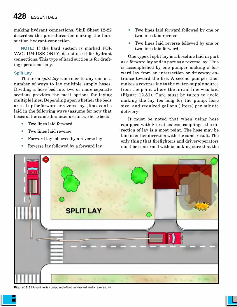
Reverse LayWith the reverse lay, hose is laid from the fire
to the water source. This method is used when a
Figure 12.76 The reverse lay proceeds from the scene to the water source.
pumper must first go to the fire location so thata size-up can be made before laying a supply line(Figure 12.76). It is also the most expedient wayto lay hose if the apparatus that lays the hosemust stay at the water source such as whendrafting or boosting hydrant pressure to thesupply line. Hose beds set up for reverse laysshould be loaded so that the first coupling tocome off the hose bed is male (Figure 12.77).
Figure 12.77 Setup hose beds forreverse lays so thatthe first coupling tocome off the hosebed is male.

426 ESSENTIALS
Laying hose from the incident scene back to thewater source has become a standard method forsetting up a relay pumping operation when usingmedium diameter hose as a supply line. Withmedium diameter hose, it is necessary in mostcases to place a pumper at the hydrant to supple-ment hydrant pressure to the supply hose. It is, ofcourse, always necessary to place a pumper at thewater source when drafting. The reverse lay is themost direct way to supplement hydrant pressureand perform drafting operations.
A disadvantage with the reverse lay, however,is that essential fire fighting equipment, includingattack hose, must be removed and placed at the firelocation before the pumper can proceed to thewater source. This causes some delay in the initialattack. The reverse lay also obligates one person,the pump operator, to stay with the pumper at thewater source, thus preventing that person fromperforming other essential fire-location activities.
A common operation involving two pumpers —an attack pumper and a water-supply pumper —calls for the first-arriving pumper to go directly tothe scene to start an initial attack on the fire usingwater from its tank, while the second-arriving
pumper lays the supply line from the attack pumperback to the water source. This is a relatively simpleoperation because the second pumper needs only toconnect its just-laid hose to a discharge outlet,connect a suction hose, and begin pumping.
When reverse-laying a supply hose, it is notnecessary to use a four-way hydrant valve. One canbe used, however, if it is expected that the pumperwill later disconnect from the supply hose andleave the hose connected to the hydrant. Thissituation may be desirable when the demand forwater diminishes to the point that the secondpumper can be made available for response to otherincidents. As with a forward lay, using the four-way valve in a reverse lay provides the means toswitch from pump pressure to hydrant pressurewithout interrupting the flow.
The reverse lay is also used when the firstpumper arrives at a fire and must work alone for anextended period of time. In this case, the hose laidin reverse becomes an attack line. It is often con-nected to a reducing wye so that two smaller hosescan be used to make a two-directional attack on thefire (Figure 12.78). The reverse-lay proceduresoutlined in Skill Sheet 12-20 describe how the
Figure 12.78 A reverse lay using wyed hoselines in operation.
Fire Hose 427
second pumper lays a line from an attack pumperto a hydrant (Figure 12.79). They can be modifiedto accommodate most types of apparatus, hose, andequipment.
MAKING HYDRANT CONNECTIONS WITH SOFT SLEEVE
HOSE
Frequently, firefighters will assist pumperdriver/operators in making hydrant connectionsfollowing a reverse lay. Either soft sleeve or hardsuction intake hose designed for hydrant opera-tions may be used to connect to hydrants. Hardsuction hose must be used when drafting from astatic water supply source. Skill Sheet 12-21 illus-trates the procedures for making a soft sleeveconnection to a hydrant.
Not all hydrants have large steamer dischargescapable of accepting direct connections from softsleeve hoses. Operations on hydrants equippedwith two 2¹�₂-inch (65 mm) outlets require the useof two 2¹�₂- or 3-inch (65 mm or 77 mm) hose-lines (Figure 12.80). These smaller intake hosescan be connected to a siamese at the pump. It ismore efficient to connect a 4¹�₂-inch (115 mm) orlarger intake hose to a hydrant with only 2¹�₂-inch(65 mm) outlets. Such a connection is made byusing a 4¹�₂-inch (115 mm) hose, or whatever sizeintake hose coupling is used, and connecting it to a2¹�₂-inch (65 mm) reducer coupling.
MAKING HYDRANT CONNECTIONS WITH HARD SUCTION
HOSE
Connecting a pumper to a fire hydrant involvescoordination and teamwork. More people are neededto connect hard suction hose than are needed to
Figure 12.79 The supply pumper lays a reverse supply line from the attack pumper.
connect soft sleeve hose. Making hydrant con-nections with a hard suction hose is also consid-erably more difficult than making connectionswith a soft sleeve hose. The first aspect that isimportant is the positioning of the pumper fromthe hydrant. No definite rule can be given todetermine this distance because not all hydrantsare the same distance from the curb or road edge,and the hydrant outlet may not directly face thestreet or road. Another determining factor isthat while most apparatus have pump intakes onboth sides, others may also have one at the frontor rear. It is considered good policy to stop theapparatus with the intake of choice just short ofthe hydrant outlet. Depending on local prefer-ences, the hard suction hose may be hooked toeither the apparatus or the hydrant first when
Figure 12.80 Two smaller supply lines may be used to connect thepumper to a hydrant that lacks a large steamer connection.
428 ESSENTIALS
making hydrant connections. Skill Sheet 12-22describes the procedures for making the hardsuction hydrant connection.
NOTE: If the hard suction is marked FORVACUUM USE ONLY, do not use it for hydrantconnections. This type of hard suction is for draft-ing operations only.
Split LayThe term split lay can refer to any one of a
number of ways to lay multiple supply hoses.Dividing a hose bed into two or more separatesections provides the most options for layingmultiple lines. Depending upon whether the bedsare set up for forward or reverse lays, lines can belaid in the following ways (assume for now thathoses of the same diameter are in two hose beds):
• Two lines laid forward
• Two lines laid reverse
• Forward lay followed by a reverse lay
• Reverse lay followed by a forward lay
• Two lines laid forward followed by one ortwo lines laid reverse
• Two lines laid reverse followed by one ortwo lines laid forward
One type of split lay is a hoseline laid in partas a forward lay and in part as a reverse lay. Thisis accomplished by one pumper making a for-ward lay from an intersection or driveway en-trance toward the fire. A second pumper thenmakes a reverse lay to the water-supply sourcefrom the point where the initial line was laid(Figure 12.81). Care must be taken to avoidmaking the lay too long for the pump, hosesize, and required gallons (liters) per minutedelivery.
It must be noted that when using hoseequipped with Storz (sexless) couplings, the di-rection of lay is a moot point. The hose may belaid in either direction with the same result. Theonly thing that firefighters and driver/operatorsmust be concerned with is making sure that the
Figure 12.81 A split lay is composed of both a forward and a reverse lay.
Fire Hose 429
proper adapters are present at each end of thelay to make the appropriate connections.
Clearly, there are many other split-lay op-tions when the hose bed is divided. One of themost versatile arrangements is one in which onesection of the hose bed contains large diameterhose (LDH) and the other sections contain smalldiameter hose that can be used for either supplyor attack. A pumper set up in this manner can layLDH when the fire situation requires the pumperto lay its own supply line and work alone (layingit forward so the pumper stays at the incidentscene). Firefighters can use small diameter hoseas a supply line at fires with less demandingwater flow requirements as well as an attack lineon large fires. A split hose bed, therefore, givesthe fire officer the greatest number of choiceswhen determining the best way to use limitedresources.
HANDLING HOSELINES[NFPA 1001: 3-3.9(a); 3-3.9(b); 3-3.12(b); 3-3.14(b)]
To effectively attack and extinguish a fire,hoselines must be removed from the apparatus andadvanced to the location of the fire. The techniquesused to advance hoselines depend on how the hoseis loaded. Hoselines may be loaded preconnected toa discharge outlet or simply placed in the hose bedunconnected.
Preconnected HoselinesThe method used to pull preconnected hoselines
varies with the type of hose load that is used. Thefollowing sections describe the methods used topull and carry preconnected hose from the loadsdescribed earlier in this chapter.
PRECONNECTED FLAT LOAD
Advancing the preconnected flat load involvespulling the hose from the compartment and walk-ing toward the fire. This procedure is described inSkill Sheet 12-23.
MINUTEMAN LOAD
The minuteman load is intended to be deployedwithout dragging any of the hose on the ground.The hose is flaked off the top of the shoulder as thefirefighter advances toward the fire. This proce-dure is described in Skill Sheet 12-24.
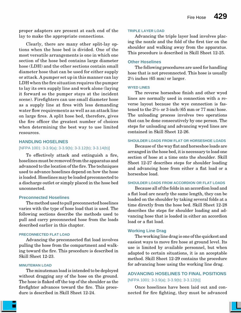
TRIPLE LAYER LOAD
Advancing the triple layer load involves plac-ing the nozzle and the fold of the first tier on theshoulder and walking away from the apparatus.This procedure is described in Skill Sheet 12-25.
Other HoselinesThe following procedures are used for handling
hose that is not preconnected. This hose is usually2¹�₂ inches (65 mm) or larger.
WYED LINES
The reverse horseshoe finish and other wyedlines are normally used in connection with a re-verse layout because the wye connection is fas-tened to the 2¹�₂- or 3-inch (65 mm or 77 mm) hose.The unloading process involves two operationsthat can be done consecutively by one person. Thesteps for unloading and advancing wyed lines arecontained in Skill Sheet 12-26.
SHOULDER LOADS FROM FLAT OR HORSESHOE LOADS
Because of the way flat and horseshoe loads arearranged in the hose bed, it is necessary to load onesection of hose at a time onto the shoulder. SkillSheet 12-27 describes steps for shoulder loadingand advancing hose from either a flat load or ahorseshoe load.
SHOULDER LOADS FROM ACCORDION OR FLAT LOADS
Because all of the folds in an accordion load anda flat load are nearly the same length, they can beloaded on the shoulder by taking several folds at atime directly from the hose bed. Skill Sheet 12-28describes the steps for shoulder loading and ad-vancing hose that is loaded in either an accordionload or a flat load.
Working Line DragThe working line drag is one of the quickest and
easiest ways to move fire hose at ground level. Itsuse is limited by available personnel, but whenadapted to certain situations, it is an acceptablemethod. Skill Sheet 12-29 contains the procedurefor advancing hose using the working line drag.
ADVANCING HOSELINES TO FINAL POSITIONS[NFPA 1001: 3-3.9(a); 3-3.9(b); 3-3.12(b)]
Once hoselines have been laid out and con-nected for fire fighting, they must be advanced
430 ESSENTIALS
into final position for applying water on the fire.The methods of deploying hose described to thispoint work well if the firefighter is simply ad-vancing hose over flat ground with no obstacles.The advancement of hoselines becomes consider-ably more difficult when other factors come intoplay. Advancing hose up and down stairways, fromstandpipes, up ladders, and into buildings are allexamples of tasks that require the firefighter toknow special techniques. These tasks are moreeasily accomplished before the hose is chargedbecause water adds considerable weight and makesthe lines less maneuverable. However, sometimesit becomes necessary to perform these tasks withcharged hoselines, and methods for handling bothdry and charged lines, where appropriate, arediscussed. Firefighters may also be involved insituations where it is necessary to extend a hoselineby adding additional hose. If a hose bursts, retriev-ing the loose hoseline and replacing the burstsection becomes necessary. These techniques arealso discussed.
Advancing Hose Into a StructureFor maximum firefighter safety, it is necessary
that firefighters be alert to the potential dangers ofbackdraft, flashover, and structural collapse, amongother things, when advancing hose into a struc-ture. The following are general safety guidelinesthat should be observed when advancing a hoselineinto a burning structure:
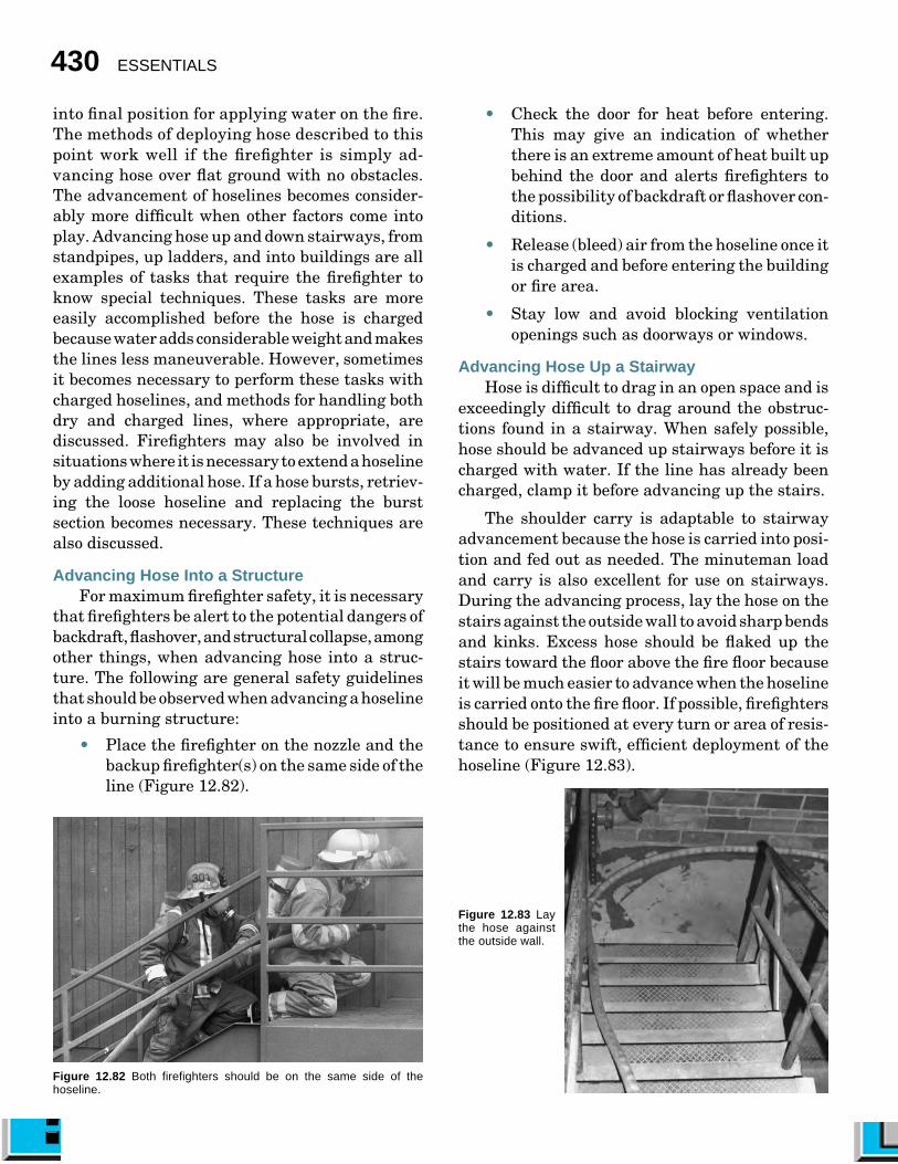
• Place the firefighter on the nozzle and thebackup firefighter(s) on the same side of theline (Figure 12.82).
Figure 12.82 Both firefighters should be on the same side of thehoseline.
• Check the door for heat before entering.This may give an indication of whetherthere is an extreme amount of heat built upbehind the door and alerts firefighters tothe possibility of backdraft or flashover con-ditions.
• Release (bleed) air from the hoseline once itis charged and before entering the buildingor fire area.
• Stay low and avoid blocking ventilationopenings such as doorways or windows.
Advancing Hose Up a StairwayHose is difficult to drag in an open space and is
exceedingly difficult to drag around the obstruc-tions found in a stairway. When safely possible,hose should be advanced up stairways before it ischarged with water. If the line has already beencharged, clamp it before advancing up the stairs.
The shoulder carry is adaptable to stairwayadvancement because the hose is carried into posi-tion and fed out as needed. The minuteman loadand carry is also excellent for use on stairways.During the advancing process, lay the hose on thestairs against the outside wall to avoid sharp bendsand kinks. Excess hose should be flaked up thestairs toward the floor above the fire floor becauseit will be much easier to advance when the hoselineis carried onto the fire floor. If possible, firefightersshould be positioned at every turn or area of resis-tance to ensure swift, efficient deployment of thehoseline (Figure 12.83).
Figure 12.83 Laythe hose againstthe outside wall.

Fire Hose 431
Advancing Hose Down a StairwayThe advancement of an uncharged (dry) hoseline
down a flight of stairs is considerably easier thanadvancing a charged hose. But because advancinga hoseline down a stairway often subjectsfirefighters to intense heat, the hoseline should becharged in most cases. Advancing an unchargedline downstairs is recommended only when there isno fire present or it is very minor.
Advancing a charged hoseline down a stairwayis difficult because of the awkwardness of the firehose. Increasing heat from the fire floor also makesthe surroundings unfavorable. It is necessary tohave all available hose at the fire floor because theadvance must be made quickly because of these hotconditions. Firefighters must be stationed at criti-cal points — corners and obstructions — to helpfeed the hose and to keep it on the outside of thestaircase.
Advancing Hose From a StandpipeFighting fires in tall buildings presents the
problem of getting hose to upper floors. Whilehoselines may be pulled from the apparatus andextended to the fire area, it is not considered goodpractice. It is more practical to have some hoserolled or folded on the apparatus ready for standpipeuse.
The manner in which standpipe hose is ar-ranged is a matter of department standard operat-ing procedures. It may be in the form of folds orbundles that are easily carried on the shoulder orin specially designed hose packs complete withnozzles, fittings, and tools (Figure 12.84).
Hose should be brought to the fire floor by thestairway. Fire crews should stop one floor belowthe fire floor and make the connection to thestandpipe. The standpipe connection is usually inthe stairwell or just outside the stairwell door.Firefighters can also use the floor below to get ageneral idea of the layout of the fire floor.
Upon reaching the standpipe, detach the build-ing hoseline or outlet cap (whichever is present),check the connection for the correct adapters (ifneeded), check for foreign objects in the discharge,and connect the fire department hose to thestandpipe (Figures 12.85 a and b). Be alert for
pressure relief devices and follow department stan-dard operating procedures for removal or connec-tion. If 1¹�₂-, 1³�₄-, or 2-inch (38 mm, 45 mm, or 50mm) hose is used, it is a good practice to place agated wye either on the standpipe or at the end ofa short piece of 2¹�₂-inch (65 mm) hose connected tothe standpipe. A 2¹�₂-inch (65 mm) attack line mayalso be used depending on the size and nature ofthe fire. Once the standpipe connection is com-pleted, any extra hose should be flaked up thestairs toward the floor above the fire (Figure 12.86).Charged hoselines as well as dry lines may beadvanced in this manner.
Figure 12.84 The components of a typical hose bundle.
Figure 12.85a Check thedischarge for debris.
Figure 12.85b Connect to thedischarge.

432 ESSENTIALS
During pickup operations, the water containedin the hoselines should be carefully drained toprevent unnecessary water damage. This can beaccomplished by draining the hose out a window,down a stairway, or down some other suitabledrain.
Advancing Hose Up a LadderOne of the safest ways to get hose to an elevated
position is to carry it up the stairs in a bundle anddrop the end over a ledge or out a window to connectto a source. Another safe method is to hoist it up toa window or landing using a rope (see Chapter 6,Ropes and Knots). However, sometimes these meth-ods cannot be used, and it is necessary to advancethe hose up a ladder. Advancing fire hose up aladder can be best achieved with a line that is notcharged. If the hose is already charged with water,it is safer, quicker, and easier to drain the hose andrelieve the pressure before advancement is made.
Whenever possible, it is best to have onefirefighter at the base of the ladder to help feed thehose to the carriers and to have one firefighter heelthe ladder during the advancement. The best way
Figure 12.86 Once the standpipe connection is completed, extra hoseshould be taken up the stairs toward the floor above the fire.
to advance an uncharged hoseline up a ladder is tohave the lead firefighter drape the nozzle or endcoupling over the shoulder from the front on theside on which the hose is being carried. Thisfirefighter then advances up the ladder until thefirst fly section is reached and waits until thenext firefighter is ready to proceed. At this point,a second firefighter drapes a large loop of hoseover the shoulder and starts up the ladder. If theladder is a three-section ladder, a third firefightermay continue the process once the secondfirefighter reaches the first fly section (Figure12.87). To avoid overloading the ladder, only oneperson should be allowed on each section of the
Figure 12.87 The hose may be carried up the ladder on the firefighters’shoulders.

Fire Hose 433
ladder. Rope hose tools or utility straps can alsobe used for this advancement (Figure 12.88). Thehose can be charged once it has reached its pointof intended use.
In those cases where it is absolutely necessaryto advance a charged line up a ladder, firefightersshould position themselves on the ladder withinreach of each other. Each firefighter should beattached to the ladder via a leg lock or ladder beltbecause both hands are required to move thecharged line. The hose is then pushed upward fromfirefighter to firefighter. The firefighter on thenozzle takes the line into the window, and the otherfirefighters continue to hoist additional hose asnecessary.
Figure 12.88 Rope hose tools may be used to carry hose up the ladder.
WARNINGCaution must be exercised to ensure that
the rated capacity of the ladder is notexceeded. If the hose cannot be passed upthe ladder without exceeding the load limit,another method of advancing the hoseline,
such as by hoisting, should be used.
Sometimes it is necessary to operate the hoselinefrom the ladder. The hoseline is first passed up theladder as previously stated. The hose should besecured to the ladder with a hose strap at a pointseveral rungs below the one on which thenozzleperson is standing (Figure 12.89). Allfirefighters on the ladder must use a leg lock orladder belt to secure themselves to the ladder. Thefirefighter on the nozzle projects the nozzle throughthe ladder and holds it with a rope hose tool orsimilar aid. When the line and all firefighters onthe ladder are properly secured, the nozzle can beopened (Figure 12.90).
Figure 12.89 Secure the hoseto the ladder.
Figure 12.90 The firefightershould lock in beforeoperating the fire stream.

434 ESSENTIALS
Extending a Section of HoseOccasionally, it becomes necessary to extend
the length of a hoseline with hose of the same sizeor perhaps even smaller hose. Skill Sheet 12-30describes the procedures that may be used to ex-tend hoselines.
Retrieving a Loose HoselineA loose hoseline is one in which water is flowing
through a nozzle, an open butt, or a broken line andis not under control by firefighters. This situationis very dangerous because the loose hoseline maywhip back and forth and up and down. Firefightersand bystanders may be seriously injured or killedif they are hit by the uncontrolled whipping end.
Closing a valve at the pump or hydrant to turnoff the flow of water is the safest way to control aloose line. Another method is to position a hoseclamp at a stationary point in the hoseline. It mayalso be possible to put a kink in the hose at a pointaway from the break until the appropriate valve isclosed (Figure 12.91). To put a kink in the hose,obtain sufficient slack in the line, bend the hoseover on itself (this does not apply to LDH becauseof its size and weight when charged), and applybody weight to the bends in the hose. During thisoperation, it is helpful to place one knee directlyupon the bend and apply pressure at this point.
Figure 12.91 The hose may be kinked to stop the flow of water.
Replacing Burst SectionsA hose clamp or a kink in the hose can also be
used to stop the flow of water when replacing aburst section of hose. Two additional sections ofhose should be used to replace any one bad section.This is necessary because hoselines stretch to longerlengths when under pressure; thus the couplingsin the line are invariably farther apart than thelength of a single replacement section.
OPERATING HOSELINES
[NFPA 1001: 3-3.6(b); 3-3.7(b); 3-3.9(a); 3-3.9(b);3-3.12(b)]
In order to successfully attack a fire, a firefightermust know how to operate and control the hoseline.There are many methods that may be used. Themethod that any one particular firefighter findsmost comfortable varies depending on the size,strength, and personal preference of the firefighter.Some of the more popular techniques are describedin the following sections.
Operating Medium-Size Attack LinesThe following methods can be used with me-
dium size attack lines of 1¹�₂-, 1³�₄-, and 2-inch (38mm, 45 mm, 50 mm) hose.
ONE-FIREFIGHTER METHOD
Whenever one firefighter is required to operatea medium-size hose and nozzle, some means mustbe provided for bracing and anchoring the hoseline.To accomplish this, the firefighter should hold thenozzle with one hand and hold the hose with theother hand just behind the nozzle (Figure 12.92).The hoseline should be straight for at least 10 feet(3 m) behind the nozzle, and the firefighter shouldface the direction in which the fire stream is pro-jected. Permit the hose to cradle against the insideof the closest leg, and brace or hold it against thefront of the body and hip. Anchor the hose to theground or floor by placing the foot of the supportingleg upon the hose. If the stream is to be moved ordirected at an excessive angle from the centerline,close the nozzle, straighten the hose, and resumethe operating position.
TWO-FIREFIGHTER METHOD
The two-firefighter method of handling a nozzleon a medium-size attack line should be used when-
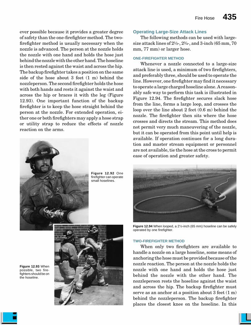
Fire Hose 435
ever possible because it provides a greater degreeof safety than the one-firefighter method. The two-firefighter method is usually necessary when thenozzle is advanced. The person at the nozzle holdsthe nozzle with one hand and holds the hose justbehind the nozzle with the other hand. The hoselineis then rested against the waist and across the hip.The backup firefighter takes a position on the sameside of the hose about 3 feet (1 m) behind thenozzleperson. The second firefighter holds the hosewith both hands and rests it against the waist andacross the hip or braces it with the leg (Figure12.93). One important function of the backupfirefighter is to keep the hose straight behind theperson at the nozzle. For extended operation, ei-ther one or both firefighters may apply a hose strapor utility strap to reduce the effects of nozzlereaction on the arms.
Figure 12.92 Onefirefighter can operatesmall hoselines.
Figure 12.93 Whenpossible, two fire-fighters should be onthe hoseline.
Operating Large-Size Attack LinesThe following methods can be used with large-
size attack lines of 2¹�₂-, 2³�₄-, and 3-inch (65 mm, 70mm, 77 mm) or larger hose.
ONE-FIREFIGHTER METHOD
Whenever a nozzle connected to a large-sizeattack line is used, a minimum of two firefighters,and preferably three, should be used to operate theline. However, one firefighter may find it necessaryto operate a large charged hoseline alone. A reason-ably safe way to perform this task is illustrated inFigure 12.94. The firefighter secures slack hosefrom the line, forms a large loop, and crosses theloop over the line about 2 feet (0.6 m) behind thenozzle. The firefighter then sits where the hosecrosses and directs the stream. This method doesnot permit very much maneuvering of the nozzle,but it can be operated from this point until help isavailable. If operation continues for a long dura-tion and master stream equipment or personnelare not available, tie the hose at the cross to permitease of operation and greater safety.
Figure 12.94 When looped, a 2¹�₂-inch (65 mm) hoseline can be safelyoperated by one firefighter.
TWO-FIREFIGHTER METHOD
When only two firefighters are available tohandle a nozzle on a large hoseline, some means ofanchoring the hose must be provided because of thenozzle reaction. The person at the nozzle holds thenozzle with one hand and holds the hose justbehind the nozzle with the other hand. Thenozzleperson rests the hoseline against the waistand across the hip. The backup firefighter mustserve as an anchor at a position about 3 feet (1 m)behind the nozzleperson. The backup firefighterplaces the closest knee on the hoseline. In this

436 ESSENTIALS
position, the backup firefighter should be kneelingon one knee with both hands on the hoseline nearthe other knee. This position prevents the hosefrom moving back or to either side. Should the hosein front try to move back or up, the backup firefighteris in a position to push it forward.
Another two-firefighter method uses hose ropetools to assist in anchoring the hose. Thenozzleperson loops a hose rope tool or utility straparound the hose a short distance from the nozzleand places the large loop across the back and overthe outside shoulder. The nozzle is then held withone hand, and the hose just behind the nozzle isheld with the other hand. The hoseline is restedagainst the body. Leaning slightly toward the nozzlehelps control the nozzle reaction. The backupfirefighter again serves as an anchor about 3 feet (1m) back. The backup firefighter also has a hoserope tool around the hose and the shoulder andleans forward to absorb some of the nozzle reaction(Figure 12.95).
THREE-FIREFIGHTER METHOD
Handling a nozzle on a large-size hoseline canbe more easily accomplished by three firefighters.There are several methods for three firefighters tocontrol large hoselines. In all cases, the positioningof the nozzleperson is the same as previously de-scribed for the two-firefighter method. The only
Figure 12.95 When possible, use a rope hose tool to help control theline.
differences will be in the position of the second andthird firefighters on the hoseline. Some depart-ments prefer the first backup firefighter to standdirectly behind the firefighter at the nozzle, withthe third firefighter kneeling on the hose behindthe second firefighter. Another method is for bothfirefighters to serve as anchors by kneeling onopposite sides of the hoseline. Another technique isfor all firefighters to use hose straps and remain ina standing position, which is the most mobilemethod (Figure 12.96).
Figure 12.96 Three firefighters make the hoseline more maneuverable.
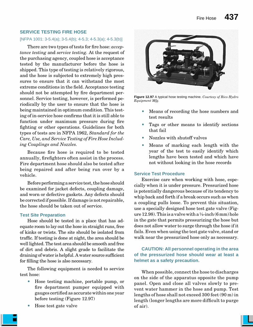
Fire Hose 437
SERVICE TESTING FIRE HOSE
[NFPA 1001: 3-5.4(a); 3-5.4(b); 4-5.3; 4-5.3(a); 4-5.3(b)]
There are two types of tests for fire hose: accep-tance testing and service testing. At the request ofthe purchasing agency, coupled hose is acceptancetested by the manufacturer before the hose isshipped. This type of testing is relatively rigorous,and the hose is subjected to extremely high pres-sures to ensure that it can withstand the mostextreme conditions in the field. Acceptance testingshould not be attempted by fire department per-sonnel. Service testing, however, is performed pe-riodically by the user to ensure that the hose isbeing maintained in optimum condition. This test-ing of in-service hose confirms that it is still able tofunction under maximum pressure during firefighting or other operations. Guidelines for bothtypes of tests are in NFPA 1962, Standard for theCare, Use, and Service Testing of Fire Hose Includ-ing Couplings and Nozzles.
Because fire hose is required to be testedannually, firefighters often assist in the process.Fire department hose should also be tested afterbeing repaired and after being run over by avehicle.
Before performing a service test, the hose shouldbe examined for jacket defects, coupling damage,and worn or defective gaskets. Any defects shouldbe corrected if possible. If damage is not repairable,the hose should be taken out of service.
Test Site PreparationHose should be tested in a place that has ad-
equate room to lay out the hose in straight runs, freeof kinks or twists. The site should be isolated fromtraffic. If testing is done at night, the area should bewell lighted. The test area should be smooth and freeof dirt and debris. A slight grade to facilitate thedraining of water is helpful. A water source sufficientfor filling the hose is also necessary.
The following equipment is needed to servicetest hose:
• Hose testing machine, portable pump, orfire department pumper equipped withgauges certified as accurate within one yearbefore testing (Figure 12.97)
• Hose test gate valve
Figure 12.97 A typical hose testing machine. Courtesy of Rico HydroEquipment Mfg.
• Means of recording the hose numbers andtest results
• Tags or other means to identify sectionsthat fail
• Nozzles with shutoff valves
• Means of marking each length with theyear of the test to easily identify whichlengths have been tested and which havenot without looking in the hose records
Service Test ProcedureExercise care when working with hose, espe-
cially when it is under pressure. Pressurized hoseis potentially dangerous because of its tendency towhip back and forth if a break occurs such as whena coupling pulls loose. To prevent this situation,use a specially designed hose test gate valve (Fig-ure 12.98). This is a valve with a ¹�₄-inch (6 mm) holein the gate that permits pressurizing the hose butdoes not allow water to surge through the hose if itfails. Even when using the test gate valve, stand orwalk near the pressurized hose only as necessary.
CAUTION: All personnel operating in the areaof the pressurized hose should wear at least ahelmet as a safety precaution.
When possible, connect the hose to dischargeson the side of the apparatus opposite the pumppanel. Open and close all valves slowly to pre-vent water hammer in the hose and pump. Testlengths of hose shall not exceed 300 feet (90 m) inlength (longer lengths are more difficult to purgeof air).
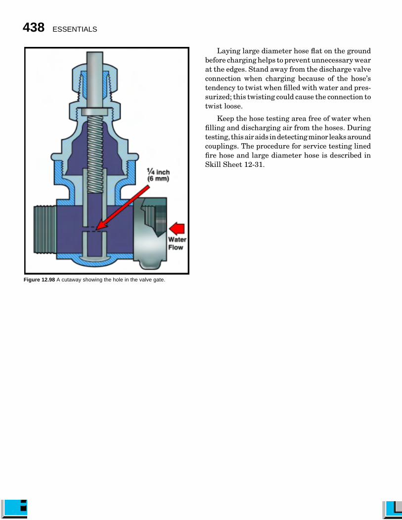
438 ESSENTIALS
Laying large diameter hose flat on the groundbefore charging helps to prevent unnecessary wearat the edges. Stand away from the discharge valveconnection when charging because of the hose’stendency to twist when filled with water and pres-surized; this twisting could cause the connection totwist loose.
Keep the hose testing area free of water whenfilling and discharging air from the hoses. Duringtesting, this air aids in detecting minor leaks aroundcouplings. The procedure for service testing linedfire hose and large diameter hose is described inSkill Sheet 12-31.
Figure 12.98 A cutaway showing the hole in the valve gate.

Fire Hose 439
Step 1: Hold the gasket between the middle finger andthumb.
Step 2: Fold the outer rim of the gasket upward by pullingwith the index finger.
Step 3. Place the gasket into the swivel by permitting thelarge loop of the gasket to enter into the coupling swivel atthe place provided.
Step 4: Release your grip on the gasket, allowing the smallloop to fall into place.
SKILL SHEET 12-1 REPLACING THE SWIVEL GASKET

440 ESSENTIALS
Step 2: Roll the male coupling over onto the hose to startthe roll.
NOTE: Form a coil that is open enough to allow the fingersto be inserted.
Step 3: Continue rolling the coupling over onto the hose,forming an even roll.
NOTE: Keep the edges of the roll aligned on the remaininghose to make a uniform roll as the roll increases in size.
Step 4: Lay the completed roll on the ground.
Step 5: Tamp any protruding coils down into the roll witha foot.
SKILL SHEET 12-2 MAKING THE STRAIGHT ROLL
Step 1: Lay out the hose straight and flat on a clean surface.

Fire Hose 441
Step 1: Lay the section of hose flat and in a straight line.
Step 2: Start the roll from a point 5 or 6 feet (1.5 m or 1.8m) off center toward the male coupling.
Step 3: Roll the hose toward the female end. Leavesufficient space at the center loop to insert a hand forcarrying.
NOTE: When the roll is complete, the male coupling will beinside the roll. The female coupling will be about 3 feet (1m) ahead of the male coupling.
Step 4: Extend the short length of hose at the female endover the male threads to protect them.
SKILL SHEET 12-3 MAKING THE DONUT ROLL
Method One
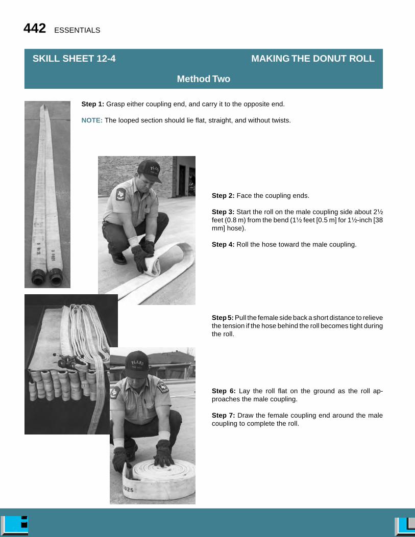
442 ESSENTIALS
Step 2: Face the coupling ends.
Step 3: Start the roll on the male coupling side about 2¹�₂
feet (0.8 m) from the bend (1¹�₂ feet [0.5 m] for 1¹�₂-inch [38mm] hose).
Step 4: Roll the hose toward the male coupling.
Step 5: Pull the female side back a short distance to relievethe tension if the hose behind the roll becomes tight duringthe roll.
Step 6: Lay the roll flat on the ground as the roll ap-proaches the male coupling.
Step 7: Draw the female coupling end around the malecoupling to complete the roll.
SKILL SHEET 12-4 MAKING THE DONUT ROLL
Method Two
Step 1: Grasp either coupling end, and carry it to the opposite end.
NOTE: The looped section should lie flat, straight, and without twists.
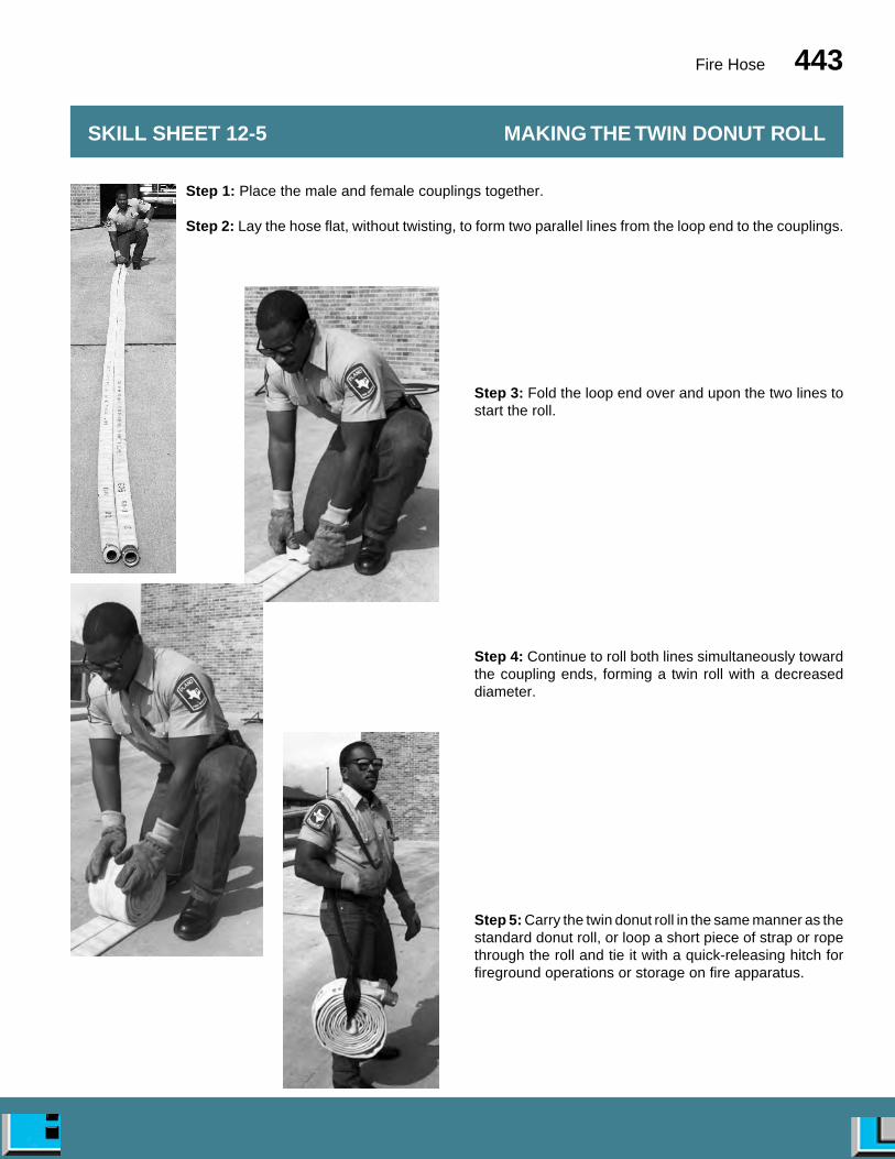
Fire Hose 443
Step 3: Fold the loop end over and upon the two lines tostart the roll.
Step 4: Continue to roll both lines simultaneously towardthe coupling ends, forming a twin roll with a decreaseddiameter.
Step 5: Carry the twin donut roll in the same manner as thestandard donut roll, or loop a short piece of strap or ropethrough the roll and tie it with a quick-releasing hitch forfireground operations or storage on fire apparatus.
SKILL SHEET 12-5 MAKING THE TWIN DONUT ROLL
Step 1: Place the male and female couplings together.
Step 2: Lay the hose flat, without twisting, to form two parallel lines from the loop end to the couplings.
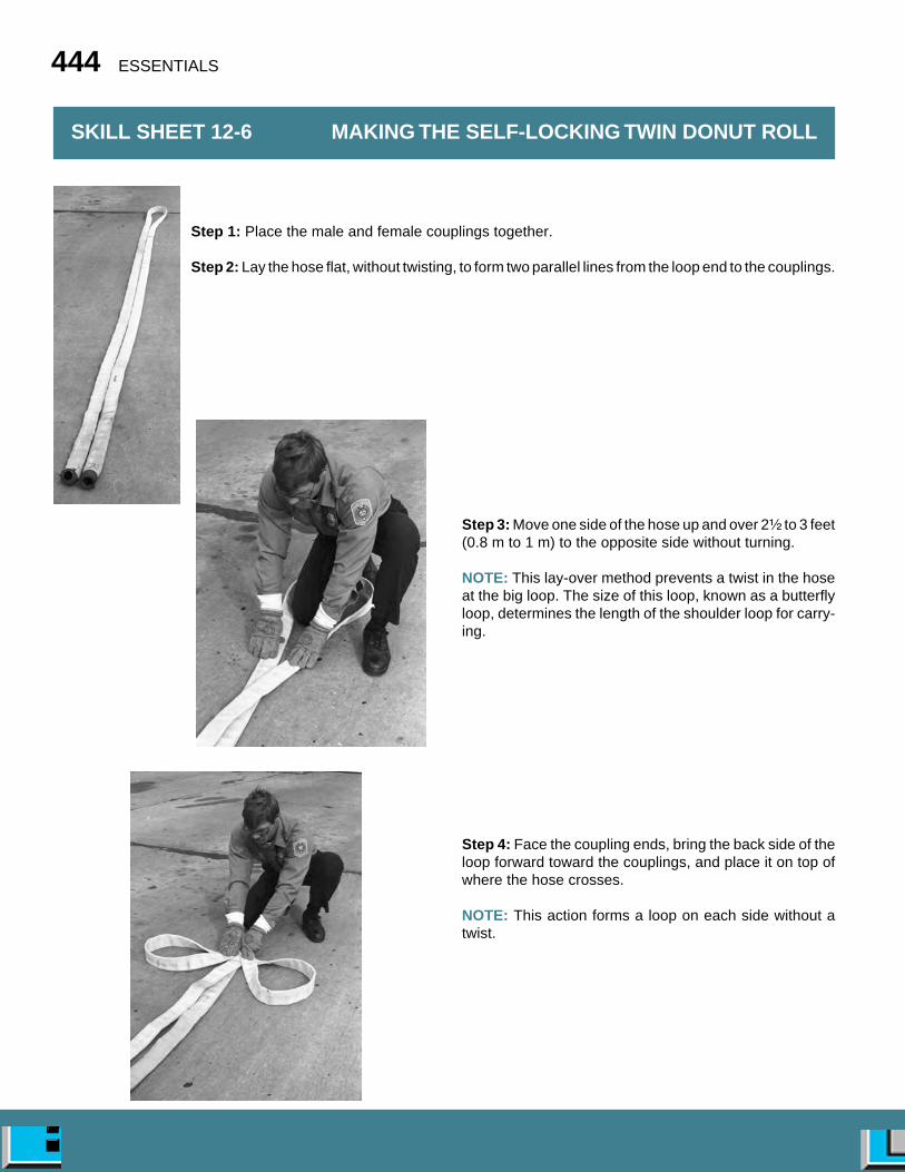
444 ESSENTIALS
Step 3: Move one side of the hose up and over 2¹⁄₂ to 3 feet(0.8 m to 1 m) to the opposite side without turning.
NOTE: This lay-over method prevents a twist in the hoseat the big loop. The size of this loop, known as a butterflyloop, determines the length of the shoulder loop for carry-ing.
Step 4: Face the coupling ends, bring the back side of theloop forward toward the couplings, and place it on top ofwhere the hose crosses.
NOTE: This action forms a loop on each side without atwist.
SKILL SHEET 12-6 MAKING THE SELF-LOCKING TWIN DONUT ROLL
Step 1: Place the male and female couplings together.
Step 2: Lay the hose flat, without twisting, to form two parallel lines from the loop end to the couplings.
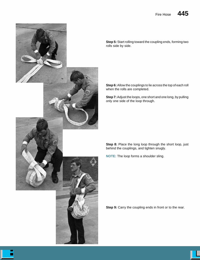
Fire Hose 445
Step 5: Start rolling toward the coupling ends, forming tworolls side by side.
Step 6: Allow the couplings to lie across the top of each rollwhen the rolls are completed.
Step 7: Adjust the loops, one short and one long, by pullingonly one side of the loop through.
Step 8: Place the long loop through the short loop, justbehind the couplings, and tighten snugly.
NOTE: The loop forms a shoulder sling.
Step 9: Carry the coupling ends in front or to the rear.

446 ESSENTIALS
Step 1: Stand facing the two couplings so that one foot isnear the male end.
Step 2: Place a foot on the hose directly behind the malecoupling
Step 3: Apply pressure to tilt it upward.
NOTE: Position the feet well apart for balance.
Step 4: Grasp the female end by placing one hand behindthe coupling and the other hand on the coupling swivel.
Step 5: Bring the two couplings together, and turn theswivel clockwise with thumb to make the connection.
SKILL SHEET 12-7 COUPLING HOSE
One-Firefighter Foot-Tilt Method

Fire Hose 447
SKILL SHEET 12-8 COUPLING HOSE
Two-Firefighter Method
Step 1: Firefighter #1: Grasp the male coupling with bothhands.
Step 2: Firefighter #1: Bend the hose directly behind thecoupling.
Step 3: Firefighter #1: Hold the coupling and hose tightlyagainst the upper thigh or midsection with the male threadspointed outward.
NOTE: It may help for Firefighter #1 to now look in anotherdirection in order to prevent trying to help align the cou-plings.
Step 4: Firefighter #2: Grasp the female coupling withboth hands.
Step 5: Firefighter #2: Bring the two couplings together,and align their positions.
NOTE: The alignment of the hose must be done by thefirefighter with the female coupling. The Higbee indicatorcan be used to align the couplings.
Step 6: Firefighter #2: Turn the female coupling counter-clockwise until a click is heard. This indicates that thethreads are aligned.
Step 7: Firefighter #2: Turn the female swivel clockwiseto complete the connection.

448 ESSENTIALS
Step 1: Grasp the hose behind the female coupling.
Step 2: Stand the male coupling on end.
Step 3: Set feet well apart for balance.
Step 4: Place one knee upon the hose and shank of thefemale coupling.
Step 5: Snap the swivel quickly in a counterclockwisedirection as body weight is applied to loosen the connec-tion.
SKILL SHEET 12-9 UNCOUPLING HOSE
One-Firefighter Knee-Press Method
SKILL SHEET 12-10 UNCOUPLING HOSE
Two-Firefighter Stiff-Arm Method
Step 1. Both Firefighters: Take a firm two-handed grip onyour respective coupling and press the coupling towardthe other firefighter, thereby compressing the gasket in thecoupling.
Step 2: Both Firefighters: Keep arms stiff, and use theweight of both bodies to turn each hose coupling counter-clockwise, thus loosening the connection.

Fire Hose 449
Step 1: Lay the first length of hose in the bed on edgeagainst the partition.
NOTE: Allow the female coupling to hang below the hosebed so that it can later be placed on top of the hose in theadjacent bed.
Step 2: Fold the hose at the front of the hose bed back onitself.
Step 3: Lay the hose back to the rear next to the first length.
Step 4: Fold the hose at the rear of the hose bed so thatthe bend is even with the rear edge of the bed.
Step 5: Lay the hose back to the front.
Step 6: Continue laying the hose in folds across the hosebed.
NOTE: Stagger the folds at the rear edge of the bed so thatevery other bend is approximately 2 inches (50 mm)shorter than the edge of the bed. This stagger may also bedone at the front of the bed if desired.
Step 7: Angle the hose upward to start the next tier.
SKILL SHEET 12-11 MAKING THE ACCORDION LOAD
Split Bed/Reverse Lay

450 ESSENTIALS
Step 8: Make the first fold of the second tier directly overthe last fold of the first tier at the rear of the bed.
Step 9: Continue with the second tier in the same manneras the first, progressively laying the hose in folds acrossthe hose bed.
NOTE: Stagger the folds as before so that every otherbend is approximately 2 inches (50 mm) inside adjacentbends.
Step 10: Make the third and succeeding tiers in the samemanner as the first two tiers.
Step 11: Move to the opposite hose bed.
Step 12: Load the hose in the same manner as the firstside.
NOTE: Start by placing the first female coupling againstthe front wall of the hose bed so that it will be pulled straightfrom the bed when this section of hose is pulled.
Step 13: Connect the last coupling on top with the femalecoupling from the first side when the load is completed.
Step 14: Lay the connected couplings on top of the hoseload.
Step 15: Pull out the slack so that the crossover loop liestightly against the hose load.
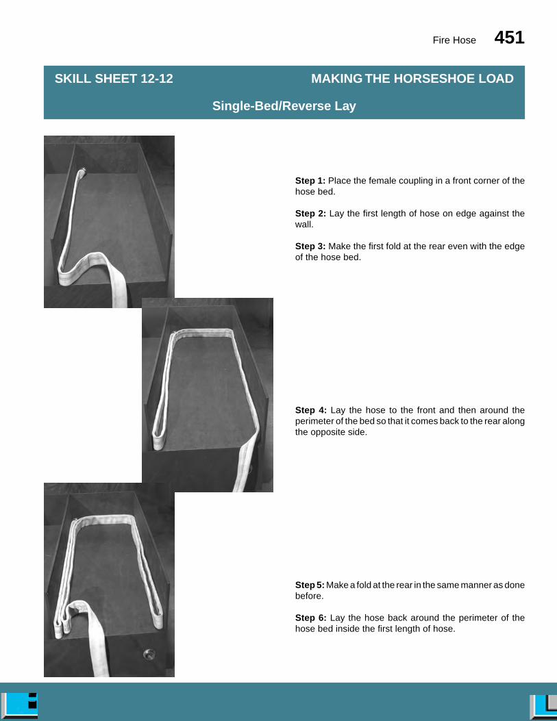
Fire Hose 451
Step 1: Place the female coupling in a front corner of thehose bed.
Step 2: Lay the first length of hose on edge against thewall.
Step 3: Make the first fold at the rear even with the edgeof the hose bed.
Step 4: Lay the hose to the front and then around theperimeter of the bed so that it comes back to the rear alongthe opposite side.
Step 5: Make a fold at the rear in the same manner as donebefore.
Step 6: Lay the hose back around the perimeter of thehose bed inside the first length of hose.
SKILL SHEET 12-12 MAKING THE HORSESHOE LOAD
Single-Bed/Reverse Lay
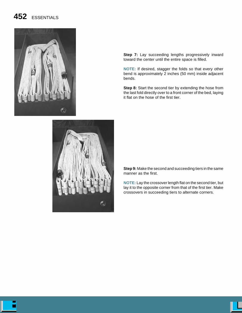
452 ESSENTIALS
Step 7: Lay succeeding lengths progressively inwardtoward the center until the entire space is filled.
NOTE: If desired, stagger the folds so that every otherbend is approximately 2 inches (50 mm) inside adjacentbends.
Step 8: Start the second tier by extending the hose fromthe last fold directly over to a front corner of the bed, layingit flat on the hose of the first tier.
Step 9: Make the second and succeeding tiers in the samemanner as the first.
NOTE: Lay the crossover length flat on the second tier, butlay it to the opposite corner from that of the first tier. Makecrossovers in succeeding tiers to alternate corners.

Fire Hose 453
NOTE: The right bed is loaded for a reverse lay, and theleft bed is loaded for a forward lay (combination load).When both beds are connected, they can be used fora reverse lay.
Step 1: Lay the first length of hose flat in the bed againstthe partition with the female coupling (which will be con-nected later to hose in the adjacent bed) hanging below thehose bed.
Step 2: Fold the hose back on itself at the front of the hosebed.
Step 3: Lay the hose back to the rear on top of the previouslength.
Step 4: Fold the hose so that the bend is even with the rearedge of the bed.
Step 5: Lay the hose back to the front of the bed, anglingit to make the front fold adjacent to the previous fold.
SKILL SHEET 12-13 MAKING THE FLAT LOAD
Split-Bed Combination Load

454 ESSENTIALS
Step 6: Continue to lay the hose in folds progressivelyacross the bed to complete the first tier.
Step 7: Continue with the second tier in the same manneras the first, laying the hose in folds progressively acrossthe hose bed.
NOTE: If desired, make the folds of the second tierapproximately 2 inches (50 mm) shorter than the folds ofthe first tier.
Step 8: Make the third and succeeding tiers in the samemanner as the first and second tiers.
NOTE: Align the bends of the third tier even with those ofthe first tier, the bends of the fourth tier even with those ofthe second tier, and so on until the load is completed.
Step 9: Move to the opposite hose bed.
Step 10: Load the hose in the same manner as the firstside.
NOTE: Start by placing the first male coupling against thefront wall of the hose bed so that it will be pulled straightfrom the bed when this last section of hose is pulled.
Step 11: Connect the last coupling on top when theopposite side is loaded with the female coupling from thefirst side (use a double male coupling).
Step 12: Lay the connected couplings on top of the hoseload.
Step 13: Pull out the slack so that the crossover loop liestightly against the hose load.
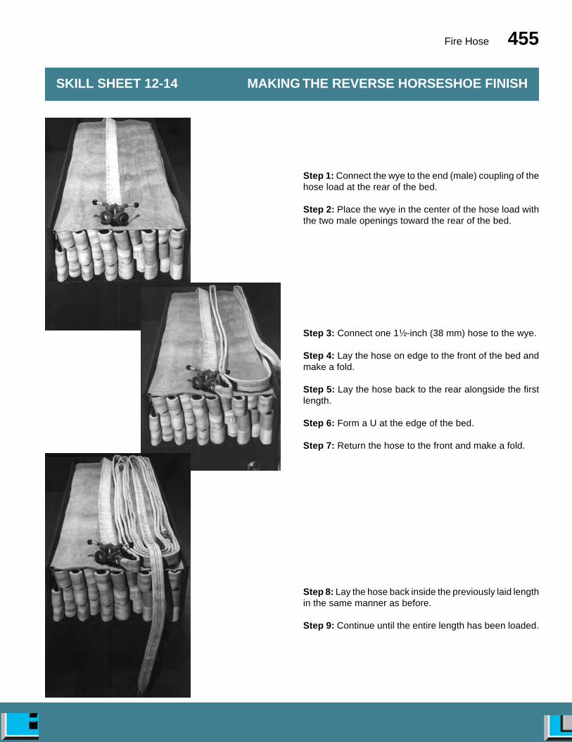
Fire Hose 455
Step 1: Connect the wye to the end (male) coupling of thehose load at the rear of the bed.
Step 2: Place the wye in the center of the hose load withthe two male openings toward the rear of the bed.
Step 3: Connect one 1¹⁄₂-inch (38 mm) hose to the wye.
Step 4: Lay the hose on edge to the front of the bed andmake a fold.
Step 5: Lay the hose back to the rear alongside the firstlength.
Step 6: Form a U at the edge of the bed.
Step 7: Return the hose to the front and make a fold.
Step 8: Lay the hose back inside the previously laid lengthin the same manner as before.
Step 9: Continue until the entire length has been loaded.
SKILL SHEET 12-14 MAKING THE REVERSE HORSESHOE FINISH
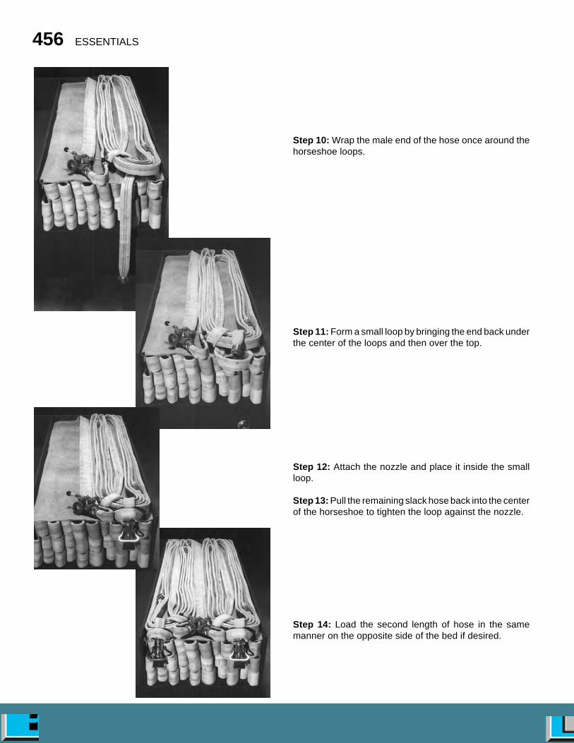
456 ESSENTIALS
Step 10: Wrap the male end of the hose once around thehorseshoe loops.
Step 11: Form a small loop by bringing the end back underthe center of the loops and then over the top.
Step 12: Attach the nozzle and place it inside the smallloop.
Step 13: Pull the remaining slack hose back into the centerof the horseshoe to tighten the loop against the nozzle.
Step 14: Load the second length of hose in the samemanner on the opposite side of the bed if desired.
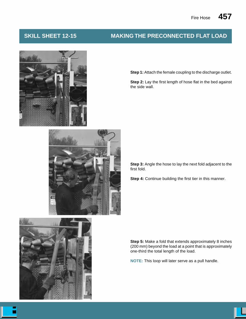
Fire Hose 457
Step 1: Attach the female coupling to the discharge outlet.
Step 2: Lay the first length of hose flat in the bed againstthe side wall.
Step 3: Angle the hose to lay the next fold adjacent to thefirst fold.
Step 4: Continue building the first tier in this manner.
Step 5: Make a fold that extends approximately 8 inches(200 mm) beyond the load at a point that is approximatelyone-third the total length of the load.
NOTE: This loop will later serve as a pull handle.
SKILL SHEET 12-15 MAKING THE PRECONNECTED FLAT LOAD
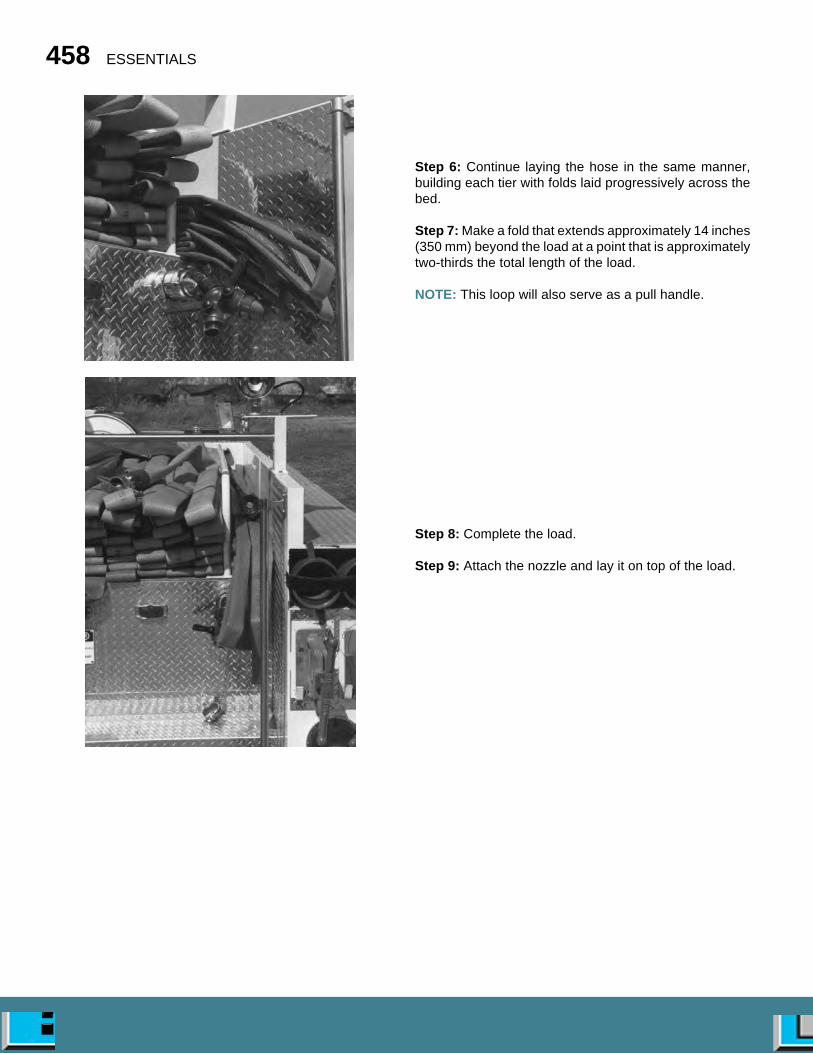
458 ESSENTIALS
Step 6: Continue laying the hose in the same manner,building each tier with folds laid progressively across thebed.
Step 7: Make a fold that extends approximately 14 inches(350 mm) beyond the load at a point that is approximatelytwo-thirds the total length of the load.
NOTE: This loop will also serve as a pull handle.
Step 8: Complete the load.
Step 9: Attach the nozzle and lay it on top of the load.

Fire Hose 459
NOTE: Start the load with the sections of hose con-nected.
Step 1: Connect the female coupling to the dischargeoutlet.
Step 2: Extend the hose in a straight line to the rear.
Step 3: Pick up the hose at a point two-thirds the distancefrom the tailboard to the nozzle.
Step 4: Carry this hose to the tailboard.
NOTE: This will form three layers of hose stacked one onthe other with a fold at each end.
Step 5: Use several people to pick up the entire length ofthe three layers.
Step 6: Begin laying the hose into the bed by folding overthe three layers into the hose bed.
SKILL SHEET 12-16 MAKING THE TRIPLE LAYER LOAD
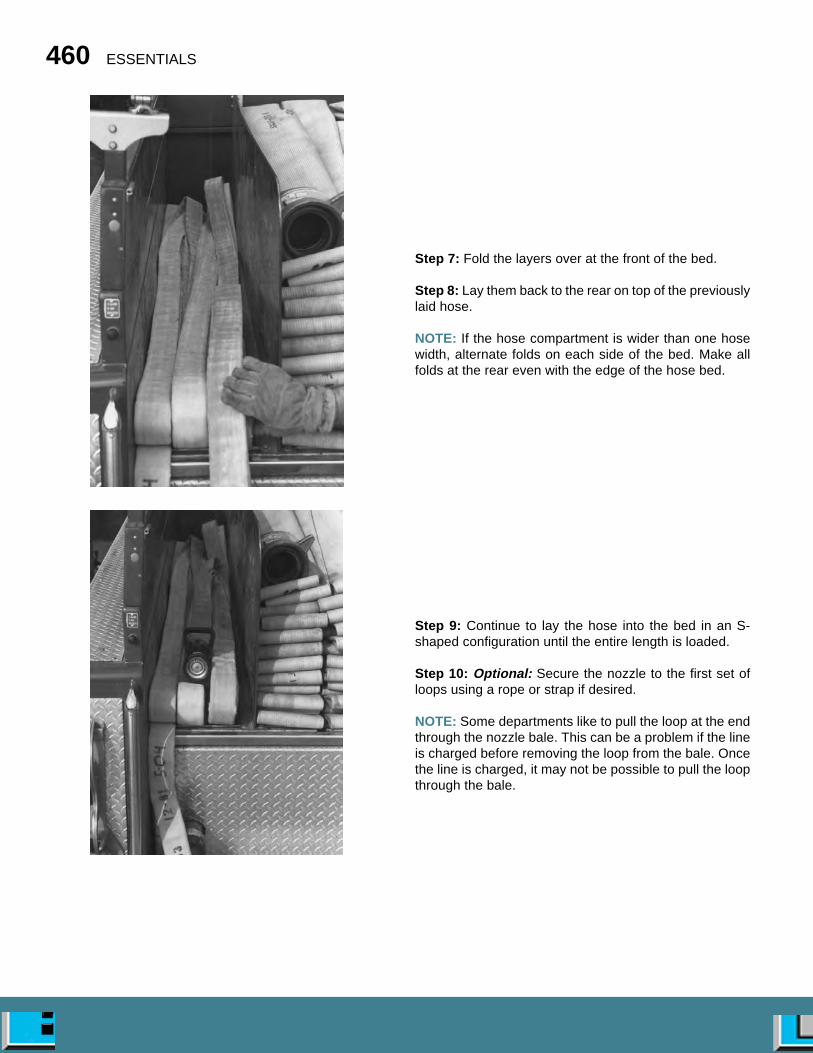
460 ESSENTIALS
Step 7: Fold the layers over at the front of the bed.
Step 8: Lay them back to the rear on top of the previouslylaid hose.
NOTE: If the hose compartment is wider than one hosewidth, alternate folds on each side of the bed. Make allfolds at the rear even with the edge of the hose bed.
Step 9: Continue to lay the hose into the bed in an S-shaped configuration until the entire length is loaded.
Step 10: Optional: Secure the nozzle to the first set ofloops using a rope or strap if desired.
NOTE: Some departments like to pull the loop at the endthrough the nozzle bale. This can be a problem if the lineis charged before removing the loop from the bale. Oncethe line is charged, it may not be possible to pull the loopthrough the bale.

Fire Hose 461
Step 1: Connect the first section of hose to the dischargeoutlet. Do not connect it to the other lengths of hose.
Step 2: Lay the hose flat in the bed to the front.
Step 3: Lay the remaining hose out the front of the bed tobe loaded later.
NOTE: If the discharge outlet is at the front of the bed, laythe hose to the rear of the bed and then back to the frontbefore it is set aside. This provides slack hose for pullingthe load clear of the bed.
Step 4: Couple the remaining hose sections together.
Step 5: Attach a nozzle to the male end.
Step 6: Place the nozzle on top of the first length at therear.
Step 7: Angle the hose to the opposite side of the bed andmake a fold.
Step 8: Lay the hose back to the rear.
SKILL SHEET 12-17 MAKING THE MINUTEMAN LOAD

462 ESSENTIALS
Step 9: Make a fold at the rear of the bed.
Step 10: Angle the hose back to the other side and makea fold at the front.
NOTE: The first fold or two may be longer than the othersto facilitate the pulling of the hose from the bed.
Step 11: Continue loading the hose to alternating sides ofthe bed in the same manner until the complete length isloaded.
Step 12: Connect the male coupling of the first section tothe female coupling of the last section.
Step 13: Lay the remainder of the first section in the bedin the same manner.
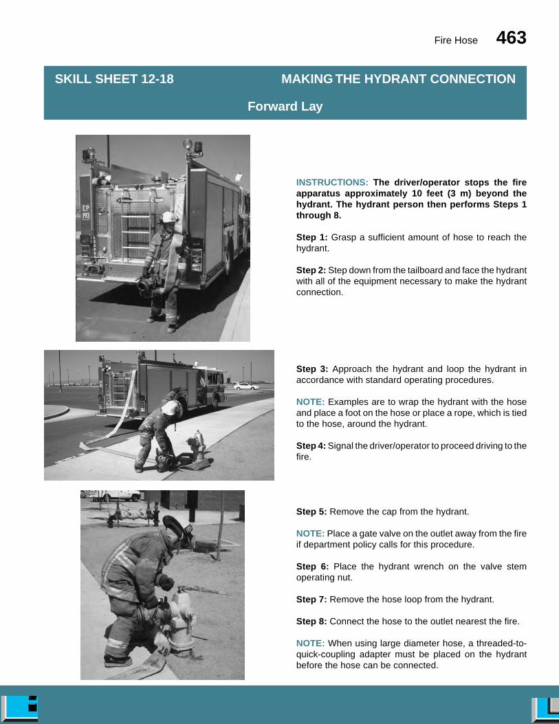
Fire Hose 463
INSTRUCTIONS: The driver/operator stops the fireapparatus approximately 10 feet (3 m) beyond thehydrant. The hydrant person then performs Steps 1through 8.
Step 1: Grasp a sufficient amount of hose to reach thehydrant.
Step 2: Step down from the tailboard and face the hydrantwith all of the equipment necessary to make the hydrantconnection.
Step 3: Approach the hydrant and loop the hydrant inaccordance with standard operating procedures.
NOTE: Examples are to wrap the hydrant with the hoseand place a foot on the hose or place a rope, which is tiedto the hose, around the hydrant.
Step 4: Signal the driver/operator to proceed driving to thefire.
Step 5: Remove the cap from the hydrant.
NOTE: Place a gate valve on the outlet away from the fireif department policy calls for this procedure.
Step 6: Place the hydrant wrench on the valve stemoperating nut.
Step 7: Remove the hose loop from the hydrant.
Step 8: Connect the hose to the outlet nearest the fire.
NOTE: When using large diameter hose, a threaded-to-quick-coupling adapter must be placed on the hydrantbefore the hose can be connected.
SKILL SHEET 12-18 MAKING THE HYDRANT CONNECTION
Forward Lay

464 ESSENTIALS
INSTRUCTIONS: The driver/operator and other crewmembers complete Steps 9 through 14.
Step 9: Complete the hose lay to the scene.
Step 10: Apply the hose clamp on the supply line 20 feet(6 m) behind the apparatus. NOTE: This allows room toremove fire fighting attack lines.
Step 11: Give the signal to charge the line.
NOTE: Signaling to charge the line can be accomplishedby using hand signals, a hand light, a radio, a bell, a siren,or an air horn.
Step 12: Uncouple the hose from the bed (allowing enoughhose to reach the pump inlet).
Step 13: Connect the hose to the pump.
Step 14: Release the hose clamp.
INSTRUCTIONS: The hydrant person completes Steps15 and 16.
Step 15: Open the hydrant fully when the appropriateorder or signal is given.
Step 16: Return to the apparatus, tightening leakingcouplings, and pushing the hose toward the curb along theway.
NOTE: If multiple lines are laid, follow the same proce-dures as those given for a single line.
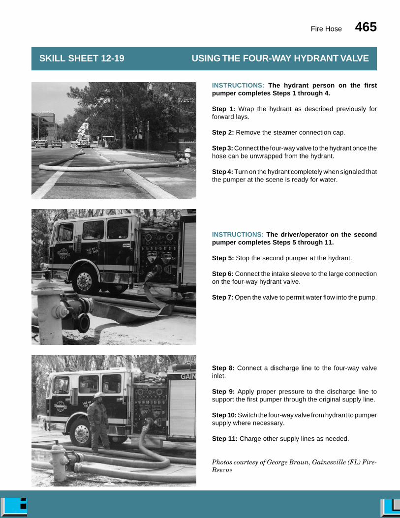
Fire Hose 465
INSTRUCTIONS: The hydrant person on the firstpumper completes Steps 1 through 4.
Step 1: Wrap the hydrant as described previously forforward lays.
Step 2: Remove the steamer connection cap.
Step 3: Connect the four-way valve to the hydrant once thehose can be unwrapped from the hydrant.
Step 4: Turn on the hydrant completely when signaled thatthe pumper at the scene is ready for water.
INSTRUCTIONS: The driver/operator on the secondpumper completes Steps 5 through 11.
Step 5: Stop the second pumper at the hydrant.
Step 6: Connect the intake sleeve to the large connectionon the four-way hydrant valve.
Step 7: Open the valve to permit water flow into the pump.
Step 8: Connect a discharge line to the four-way valveinlet.
Step 9: Apply proper pressure to the discharge line tosupport the first pumper through the original supply line.
Step 10: Switch the four-way valve from hydrant to pumpersupply where necessary.
Step 11: Charge other supply lines as needed.
Photos courtesy of George Braun, Gainesville (FL) Fire-Rescue
SKILL SHEET 12-19 USING THE FOUR-WAY HYDRANT VALVE

466 ESSENTIALS
INSTRUCTIONS: Both the driver/operator of Pumper#2 and a firefighter perform Steps 1 through 5.
Step 1: Driver/Operator of Pumper #2: Stop the secondapparatus where its tailboard is slightly beyond the intakevalve of the attack pumper.
Step 2: Firefighter: Pull sufficient hose to reach the intakevalve.
Step 3: Firefighter: Anchor the hose.
NOTE: Anchor the hose to a secure object if possible.
Step 4: Driver/Operator of Pumper #2: Lay out the hoseto the water source when signaled by the firefighter that thehose is anchored.
Step 5: Firefighter: Apply a hose clamp to the hose at theattack pumper.
SKILL SHEET 12-20 MAKING THE REVERSE LAY

Fire Hose 467
INSTRUCTIONS: The driver/operator of Pumper #2completes Steps 6 through 11.
Step 6: Stop the second apparatus at the hydrant.
Step 7: Make an intake hose connection.
NOTE: Make preparations for drafting if laying to a staticsource.
Step 8: Pull the remaining length of the last section of hosefrom the hose bed.
Step 9: Disconnect the couplings, and return the malecoupling to the hose bed.
Step 10: Connect the supply hose to a discharge valve.
Step 11: Charge the hose.

468 ESSENTIALS
Step 1: Position the pumper so that the pump intake iseither a few feet (meters) ahead or short of the hydrantconnection.
NOTE: This allows for a slight bend in the hose, yet avoidskinking.
Step 2: Remove the soft sleeve hose, hydrant wrench, andany adapters necessary from the pumper.
Step 3: Make pumper connection (if the intake hose is notpreconnected).
Step 4: Unroll the intake hose.
Step 5: Place the hydrant wrench on the hydrant valvestem operating nut.
NOTE: If it is a dry-barrel hydrant, point the handle awayfrom the outlet.
Step 6: Remove the hydrant cap and add any adaptersthat may be necessary.
NOTE: If an adapter is needed, it is usually used at thehydrant connection.
Step 7: Place two full twists in the hose to prevent kinkingwhen the hose is charged.
NOTE: Hose with Storz-type couplings should not betwisted.
Step 8: Connect the hose to the hydrant.
Step 9: Open the hydrant slowly.
Step 10: Tighten any leaking connections.
Step 11: Add chafing blocks to the hose where it contactsthe ground to prevent rub-induced damage by water andapparatus vibrations.
SKILL SHEET 12-21 MAKING A SOFT SLEEVE CONNECTIONTO A HYDRANT

Fire Hose 469
Step 1: Driver/Operator: Spot the pumper at a conve-nient angle to the hydrant and within the limits of the lengthof the intake hose.
Step 2: Driver/Operator: Check to see whether the boostertank valve is closed.
Step 3: Driver/Operator: Remove the pump intake cap.
Step 4: Firefighter: Remove the hydrant outlet cap.
Step 5: Firefighter: Place the hydrant wrench on thehydrant valve stem operating nut with the handle pointingaway from the outlet.
NOTE: Place an adapter on the hydrant outlet if neces-sary.
Step 6: Driver/Operator: Connect the hard suction hoseto the large intake.
NOTE: Depending on local preference, the hydrant maybe connected first.
Step 7: Firefighter: Connect the opposite end to thehydrant.
Step 8: Driver/Operator: Move the apparatus slightly toaccomplish this connection if necessary.
NOTE: Put at least a slight bend in the hose.
Step 9: Firefighter: Open the hydrant.
Step 10: Driver/Operator: Ready the pump for operation.
SKILL SHEET 12-22 MAKING A HARD SUCTION CONNECTIONTO A HYDRANT

470 ESSENTIALS
Step 1: Put one arm through the longer loop.
Step 2: Grasp the shorter pull loop with the same hand.
Step 3: Grasp the nozzle with the opposite hand.
Step 4: Pull the load from the bed using the pull loops.
Step 5: Walk toward the fire.
NOTE: As the hose pulls taut in the hand, release the handloop.
Step 6: Continue to lead in the hose.
NOTE: As the shoulder loop becomes taut, drop it to theground.
Step 7: Proceed until the hose is fully extended.
SKILL SHEET 12-23 ADVANCING THE PRECONNECTED FLAT LOAD
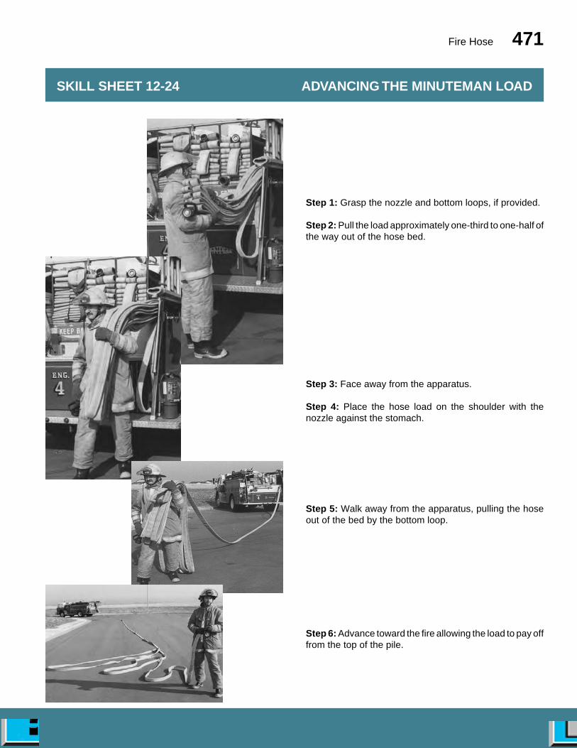
Fire Hose 471
SKILL SHEET 12-24 ADVANCING THE MINUTEMAN LOAD
Step 1: Grasp the nozzle and bottom loops, if provided.
Step 2: Pull the load approximately one-third to one-half ofthe way out of the hose bed.
Step 3: Face away from the apparatus.
Step 4: Place the hose load on the shoulder with thenozzle against the stomach.
Step 5: Walk away from the apparatus, pulling the hoseout of the bed by the bottom loop.
Step 6: Advance toward the fire allowing the load to pay offfrom the top of the pile.

472 ESSENTIALS
Step 1: Place the nozzle and fold of the first tier over theshoulder.
Step 2: Face the direction of travel.
Step 3: Walk away from the apparatus.
Step 4: Pull the hose completely out of the bed.
Step 5: Drop the folded end from the shoulder when thehose bed has been cleared.
Step 6: Advance the nozzle.
NOTE: If the direction of travel is going to be changed, thefirefighter may wish to hold onto the fold and pull all threelayers in that direction before dropping the fold and ad-vancing the nozzle.
SKILL SHEET 12-25 ADVANCING THE TRIPLE LAYER LOAD
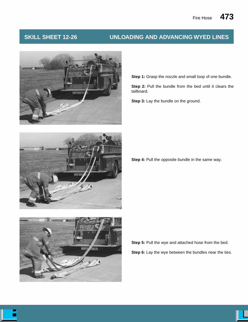
Fire Hose 473
SKILL SHEET 12-26 UNLOADING AND ADVANCING WYED LINES
Step 1: Grasp the nozzle and small loop of one bundle.
Step 2: Pull the bundle from the bed until it clears thetailboard.
Step 3: Lay the bundle on the ground.
Step 4: Pull the opposite bundle in the same way.
Step 5: Pull the wye and attached hose from the bed.
Step 6: Lay the wye between the bundles near the ties.
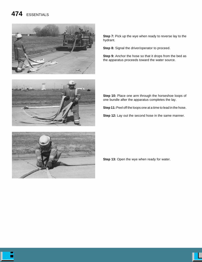
474 ESSENTIALS
Step 7: Pick up the wye when ready to reverse lay to thehydrant.
Step 8: Signal the driver/operator to proceed.
Step 9: Anchor the hose so that it drops from the bed asthe apparatus proceeds toward the water source.
Step 10: Place one arm through the horseshoe loops ofone bundle after the apparatus completes the lay.
Step 11: Peel off the loops one at a time to lead in the hose.
Step 12: Lay out the second hose in the same manner.
Step 13: Open the wye when ready for water.

Fire Hose 475
INSTRUCTIONS: Firefighter #1 performs Step 1.Firefighter #2 performs Steps 2 through 8.
Step 1: Firefighter #1: Attach the nozzle to the end of thehose if desired.
NOTE: Assist other firefighters with loading hose on theirshoulders.
Step 2: Firefighter #2: Position at the tailboard facing thedirection of travel.
Step 3: Firefighter #2: Place the initial fold of hose overthe shoulder so that the nozzle can be held at chest height.
Step 4: Firefighter #2: Bring the hose from behind backover the shoulder so that the rear fold ends at the back ofthe knee.
Step 5: Firefighter #2: Make a fold in front that ends atknee height and bring the hose back over the shoulder.
Step 6: Firefighter #2: Continue to make knee-high foldsuntil an appropriate amount of hose is loaded.
Step 7: Firefighter #2: Hold the hose to prevent it fromslipping off the shoulder.
Step 8: Firefighter #2: Move forward approximately 15
SKILL SHEET 12-27 SHOULDER LOADING AND ADVANCING HOSE
Flat or Horseshoe Loads
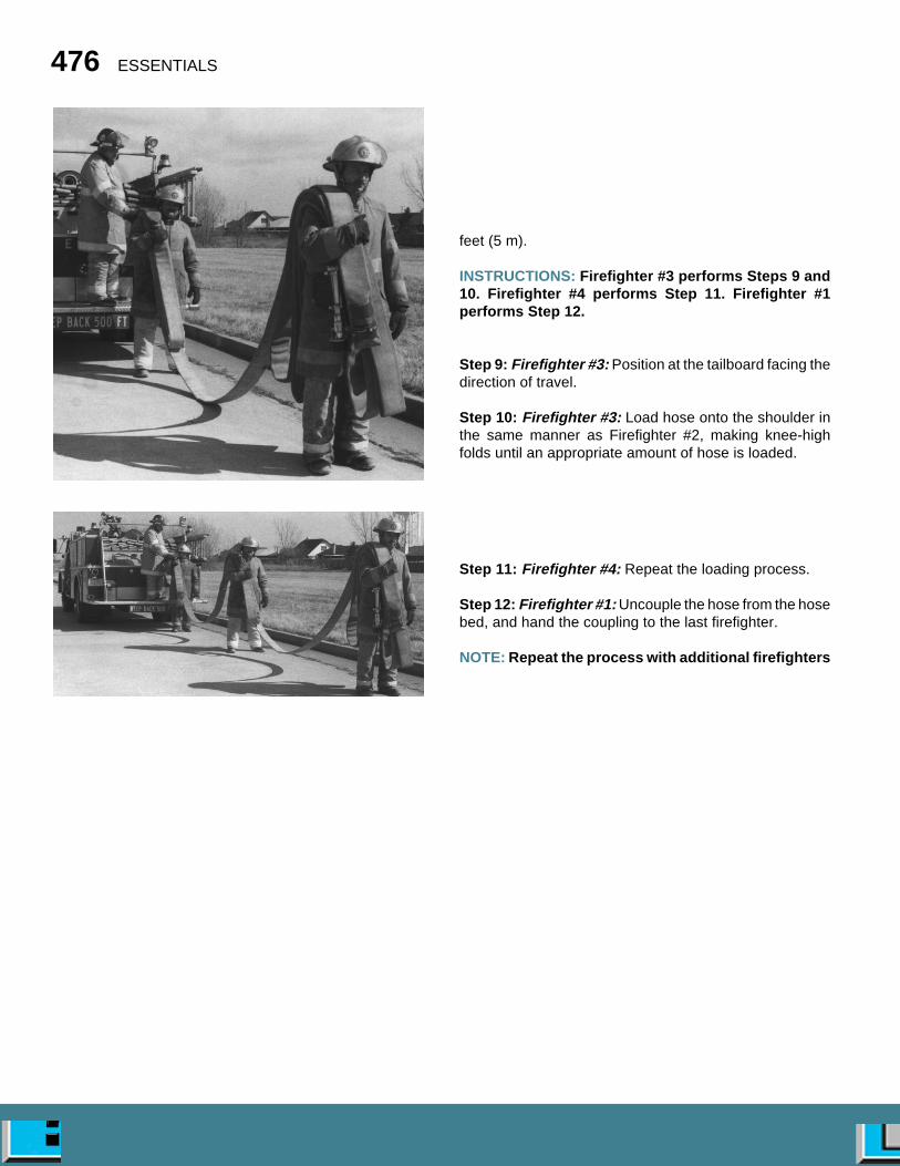
476 ESSENTIALS
feet (5 m).
INSTRUCTIONS: Firefighter #3 performs Steps 9 and10. Firefighter #4 performs Step 11. Firefighter #1performs Step 12.
Step 9: Firefighter #3: Position at the tailboard facing thedirection of travel.
Step 10: Firefighter #3: Load hose onto the shoulder inthe same manner as Firefighter #2, making knee-highfolds until an appropriate amount of hose is loaded.
Step 11: Firefighter #4: Repeat the loading process.
Step 12: Firefighter #1: Uncouple the hose from the hosebed, and hand the coupling to the last firefighter.
NOTE: Repeat the process with additional firefighters

Fire Hose 477
until the desired length of hose is loaded.
Step 1: Face the hose bed.
Step 2: Grasp the nozzle or coupling.
Step 3: Grasp with both hands the number of folds neededto make up that portion of the shoulder load.
Step 4: Pull the folds about one-third of the way out of thebed.
Step 4a: For Accordion Loads Only: Twist the folds intoan upright position.
Step 5: Turn and pivot into the folds, placing them on topof the shoulder.
NOTE: Make sure that the hose is flat on the shoulder withthe nozzle or coupling in front of the body.
Step 6: Grasp the bundle tightly with both hands.
Step 7: Step away from the apparatus, pulling the shoul-der load completely out of the bed.
NOTE: Additional firefighters may remove shoulder
SKILL SHEET 12-28 SHOULDER LOADING AND ADVANCING HOSE
Accordion or Flat Loads
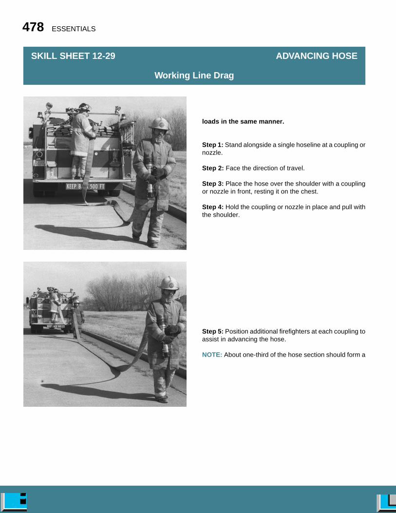
478 ESSENTIALS
loads in the same manner.
Step 1: Stand alongside a single hoseline at a coupling ornozzle.
Step 2: Face the direction of travel.
Step 3: Place the hose over the shoulder with a couplingor nozzle in front, resting it on the chest.
Step 4: Hold the coupling or nozzle in place and pull withthe shoulder.
Step 5: Position additional firefighters at each coupling toassist in advancing the hose.
NOTE: About one-third of the hose section should form a
SKILL SHEET 12-29 ADVANCING HOSE
Working Line Drag
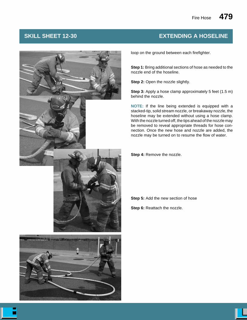
Fire Hose 479
loop on the ground between each firefighter.
Step 1: Bring additional sections of hose as needed to thenozzle end of the hoseline.
Step 2: Open the nozzle slightly.
Step 3: Apply a hose clamp approximately 5 feet (1.5 m)behind the nozzle.
NOTE: If the line being extended is equipped with astacked-tip, solid stream nozzle, or breakaway nozzle, thehoseline may be extended without using a hose clamp.With the nozzle turned off, the tips ahead of the nozzle maybe removed to reveal appropriate threads for hose con-nection. Once the new hose and nozzle are added, thenozzle may be turned on to resume the flow of water.
Step 4: Remove the nozzle.
Step 5: Add the new section of hose
Step 6: Reattach the nozzle.
SKILL SHEET 12-30 EXTENDING A HOSELINE
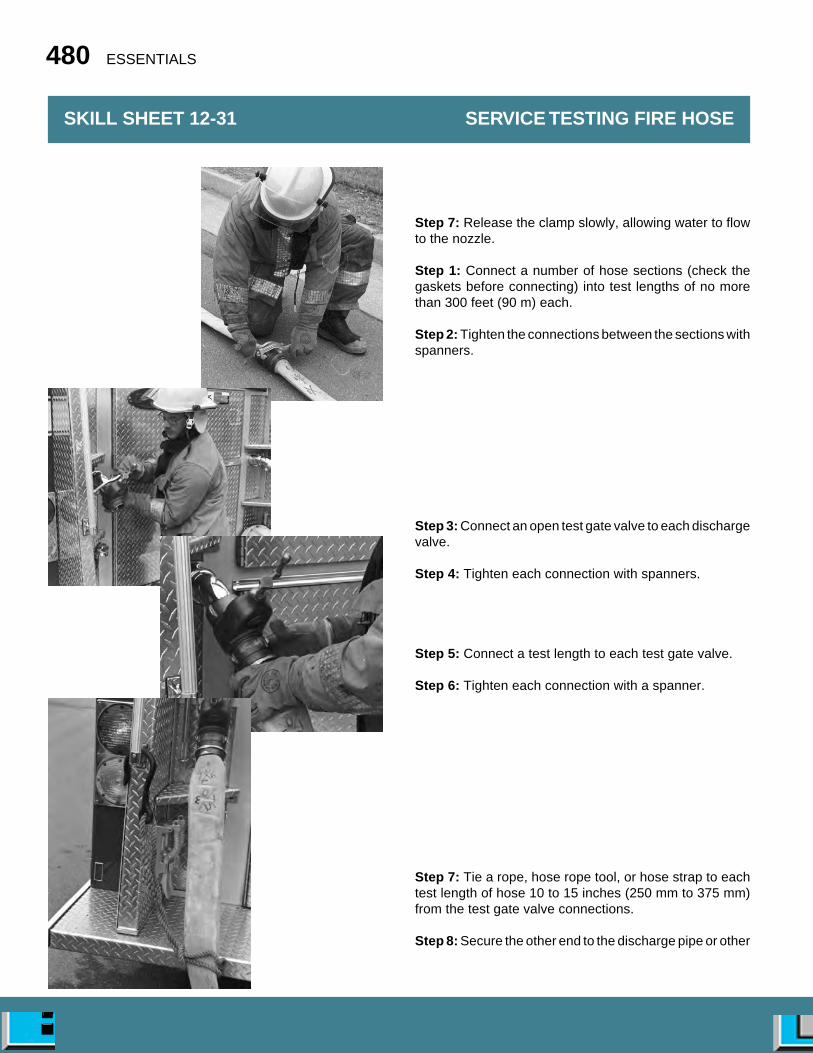
480 ESSENTIALS
Step 7: Release the clamp slowly, allowing water to flowto the nozzle.
Step 1: Connect a number of hose sections (check thegaskets before connecting) into test lengths of no morethan 300 feet (90 m) each.
Step 2: Tighten the connections between the sections withspanners.
Step 3: Connect an open test gate valve to each dischargevalve.
Step 4: Tighten each connection with spanners.
Step 5: Connect a test length to each test gate valve.
Step 6: Tighten each connection with a spanner.
Step 7: Tie a rope, hose rope tool, or hose strap to eachtest length of hose 10 to 15 inches (250 mm to 375 mm)from the test gate valve connections.
Step 8: Secure the other end to the discharge pipe or other
SKILL SHEET 12-31 SERVICE TESTING FIRE HOSE
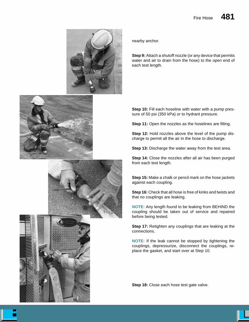
Fire Hose 481
nearby anchor.
Step 9: Attach a shutoff nozzle (or any device that permitswater and air to drain from the hose) to the open end ofeach test length.
Step 10: Fill each hoseline with water with a pump pres-sure of 50 psi (350 kPa) or to hydrant pressure.
Step 11: Open the nozzles as the hoselines are filling.
Step 12: Hold nozzles above the level of the pump dis-charge to permit all the air in the hose to discharge.
Step 13: Discharge the water away from the test area.
Step 14: Close the nozzles after all air has been purgedfrom each test length.
Step 15: Make a chalk or pencil mark on the hose jacketsagainst each coupling.
Step 16: Check that all hose is free of kinks and twists andthat no couplings are leaking.
NOTE: Any length found to be leaking from BEHIND thecoupling should be taken out of service and repairedbefore being tested.
Step 17: Retighten any couplings that are leaking at theconnections.
NOTE: If the leak cannot be stopped by tightening thecouplings, depressurize, disconnect the couplings, re-place the gasket, and start over at Step 10.
Step 18: Close each hose test gate valve.
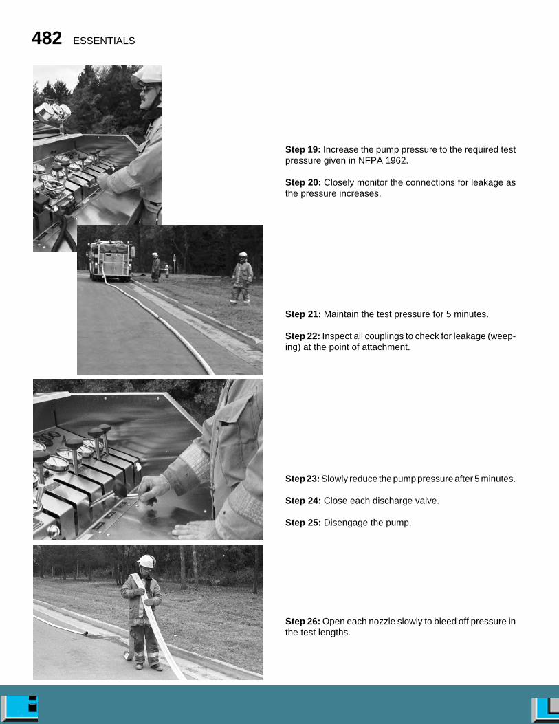
482 ESSENTIALS
Step 19: Increase the pump pressure to the required testpressure given in NFPA 1962.
Step 20: Closely monitor the connections for leakage asthe pressure increases.
Step 21: Maintain the test pressure for 5 minutes.
Step 22: Inspect all couplings to check for leakage (weep-ing) at the point of attachment.
Step 23: Slowly reduce the pump pressure after 5 minutes.
Step 24: Close each discharge valve.
Step 25: Disengage the pump.
Step 26: Open each nozzle slowly to bleed off pressure inthe test lengths.

Fire Hose 483
Step 27: Break all hose connections and drain water fromthe test area.Step 28: Observe marks placed on the hose at the cou-plings.
NOTES:• If a coupling has moved during the test, tag the hose
section for recoupling. Tag all hose that has leaked orfailed in any other way.
• Expect a ¹�₁₆- to ¹�₈-inch (2 mm to 3 mm) uniformmovement of the coupling on newly coupled hose. Thisslippage is normal during initial testing but should notoccur during subsequent tests.
Step 29: Record the test results for each section of hose.