chapter 12 commentary wood structure design
TRANSCRIPT

231
Chapter 12 Commentary
WOOD STRUCTURE DESIGN REQUIREMENTS
12.1 GENERAL 12.1.2 References. Wood construction practices have not been codified in a form that is standard throughout the country. The 2003 Provisions incorporates by reference the AF&PA ASD/LRFD Supplement, Special Design Provisions for Wind and Seismic (SDPWS) and the 2003 International Residental Code (IRC). Many wood frame structures are a combination of engineered wood and “conventional” light-frame construction. Wood also is used in combination with other materials (American Institute of Timber Construction, 1985; Breyer, 1993; Faherty and Williamson, 1989; Hoyle and Woeste, 1989; Somayaji, 1992; Stalnaker and Harris, 1989). The requirements of the model building codes were used as a resource in developing the requirements introduced in the 1991 Provisions and further modified since then. The general requirements of Chapter 12 cover construction practices necessary to provide a performance level of seismic resistance consistent with the purposes stated in Chapter 1. These requirements also may be related to gravity load capacity and wind force resistance which is a natural outgrowth of any design procedure. For the 2003 Provisions, the reference documents continue to be grouped according to their primary focus into three subsections: Sec. 12.1.2.1, Engineered Wood Construction; Sec. 12.1.2.2, Conventional Construction; and Sec. 12.1.2.3, Materials Standards.
12.2 DESIGN METHODS Prior to the publication of AF&PA/ASCE 16, typical design of wood frame structures followed the American Forest and Paper Association (AF&PA) National Design Specification for Wood Construction (NDS) (AF&PA, 1991). The NDS is based on “allowable” stresses and implied factors of safety. However, the design procedure provided by the Provisions was developed on the premise of the resistance capacity of members and connections at the yield level (ASCE, 1988; Canadian Wood Council, 1990 and 1991; Keenan, 1986). In order to accommodate this difference in philosophy, the 1994 and prior editions of the Provisions made adjustments to the tabulated “allowable” stresses in the reference documents.
With the completion of the Load and Resistance Factor Standard for Engineered Wood Construction (AF&PA/ASCE, 1995), the modifications and use of an “allowable” stress based standard was no longer necessary. Therefore, the 1997 Provisions included the LRFD standard by reference (AF&PA/ASCE 16) and used it as the primary design procedure for engineered wood construction. The use of AF&PA/ASCE 16 continues in the 2003 Provisions.
Conventional light-frame construction, a prescriptive method of constructing wood structures, is allowed for some design categories. These structures must be constructed according to the requirements set forth in Sec. 12.4 and applicable reference documents. If the construction deviates from these prescriptive requirements, the engineered design requirements of Sec. 12.2 and 12.3 and AF&PA/ASCE 16 must be followed. If a structure that is classified as conventional construction contains some structural elements that do not meet the requirements of conventional construction, the elements in question can be engineered without changing the rest of the structure to engineered construction. The extent of design to be provided must be determined by the responsible registered design professional; however, the minimum acceptable extent is often taken to be force transfer into the element, design of the element, and force transfer out of the element. This does not apply to a structure that is principally an engineered structure with minor elements that could be considered conventional. When more than one braced wall line or diaphragm in any area of a conventional residence requires design, the nature of the construction may have changed, and engineered design

2003 Commentary, Chapter 12
232
might be appropriate for the entire seismic-force-resisting system. The absence of a ceiling diaphragm may also create a configuration that is non-conventional. The requirement for engineering portions of a conventional construction structure to maintain lateral-force resistance and stiffness is added to provide displacement compatibility.
Alternate strength of members and connections. It remains the intent of the Provisions that load and resistance factor design be used. When allowable stress design is to be used, however, the factored resistance of members and connections subjected to seismic forces acting alone or in combination with other prescribed loads shall be determined using a capacity reduction factor, φ, times 2.16 times the allowable stresses permitted in the National Design Specification for Wood Construction (NDS) and supplements (AF&PA, 1991). The allowable stresses used shall not include a duration of load factor, CD. The value of the capacity reduction factor, φ, shall be as follows:
Wood members
In flexure φ = 1.00
In compression φ = 0.90
In tension φ = 1.00
In shear and torsion φ = 1.00
Connectors
Anchor bolts, bolts, lag bolts, nails, screws, etc. φ = 0.85
Bolts in single shear in members of a
seismic-force-resisting system φ = 0.40
These “soft” conversions from allowable stress design values to load and resistance factor design values first appeared in Sec. 9.2 in the 1994 Provisions. An alternative method of calculating soft conversions is provided in ASTM D 5457-93. The reader is cautioned, however, that the loads and load combinations to be used for conversion are not specified so it is incumbent upon the user to determine appropriate conversion values. Wood frame structures assigned to Seismic Design Category A, other than one- and two-family dwellings, must comply with Sec. 12.4 or if engineered need only comply with the reference documents and Sec. 1.5. Exceptions addressing one- and two-family detached dwellings appear in Sec.
12.2.1 Seismic Design Categories B, C, and D. Seismic Design Categories B, C, and D were combined in the 1997 Provisions. At the same time, subsections on material limitations and anchorage requirements were moved. This was based on the philosophy that detailing requirements should vary based on R value rather than seismic design category.
Structures assigned to Seismic Design Categories B, C, and D are required to meet the minimum construction requirements of Sec. 12.4 (Sherwood and Stroh, 1989) or must be engineered using standard design methods and principles of mechanics. Conventional light-frame construction requirements were modified in the 1991 Provisions to limit the spacing between braced wall lines based on calculated capacities to resist the loads and forces imposed.
Engineered structures assigned to Seismic Design Categories B, C, and D are required to conform to the provisions of Sec. 12.2 and 12.3. Included in these sections are general design limitations, limits on wood resisting forces contributed by concrete or masonry, shear wall and diaphragm aspect ratio limitations, and requirements for distribution of shear to vertical resisting elements.
Wood Structure Design Requirements
233
12.2.2 Seismic Design Categories E and F. If the provisions of Chapter 12 apply, Seismic Design Category E and F structures require an engineered design. Conventional construction is not considered rigorous enough for structures expected to be functional following a major seismic event. For Seismic Design Category E and F structures, close attention to load path and detailing is required.
Structures assigned to Seismic Design Category E and F require blocked diaphragms. Structural-use panels must be applied directly to the framing members; the use of gypsum wallboard between the structural-use panels and the framing members is prohibited because of the poor performance of nails in gypsum. Restrictions on allowable shear values for structural-use shear panels when used in conjunction with concrete and masonry walls are intended to provide for deformation compatibility of the different materials.
12.2.3.1 Discussion of cyclic test protocol is included in ATC (1995), Dolan (1996), and Rose (1996).
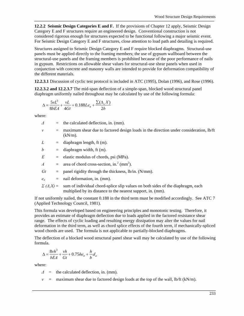
12.2.3.2 and 12.2.3.7 The mid-span deflection of a simple-span, blocked wood structural panel diaphragm uniformly nailed throughout may be calculated by use of the following formula:
3 ( )5 0.1888 4 2
cn
XvL vL LebEA Gt b
∑ ∆∆ = + + +
where:
∆ = the calculated deflection, in. (mm).
v = maximum shear due to factored design loads in the direction under consideration, lb/ft (kN/m).
L = diaphragm length, ft (m).
b = diaphragm width, ft (m).
E = elastic modulus of chords, psi (MPa).
A = area of chord cross-section, in.2 (mm2).
Gt = panel rigidity through the thickness, lb/in. (N/mm).
en = nail deformation, in. (mm).
Σ (∆cX) = sum of individual chord-splice slip values on both sides of the diaphragm, each multiplied by its distance to the nearest support, in. (mm).
If not uniformly nailed, the constant 0.188 in the third term must be modified accordingly. See ATC 7 (Applied Technology Council, 1981).
This formula was developed based on engineering principles and monotonic testing. Therefore, it provides an estimate of diaphragm deflection due to loads applied in the factored resistance shear range. The effects of cyclic loading and resulting energy dissipation may alter the values for nail deformation in the third term, as well as chord splice effects of the fourth term, if mechanically-spliced wood chords are used. The formula is not applicable to partially-blocked diaphragms.
The deflection of a blocked wood structural panel shear wall may be calculated by use of the following formula.
38 0.75 n avh vh hhe d
bEA Gt b∆ = + + +
where:
∆ = the calculated deflection, in. (mm).
v = maximum shear due to factored design loads at the top of the wall, lb/ft (kN/m).
2003 Commentary, Chapter 12
234
h = shear wall height, ft (m).
b = shear wall width, ft (m).
E = elastic modulus of boundary element (vertical member at shear wall boundary), psi (MPa).
A = area of boundary element cross-section (vertical member at shear wall boundary), in.2 (mm2).
Gt = panel rigidity through the thickness, lb/in. (N/mm).
en = nail deformation, in. (mm).
da = deflection due to anchorage details ( rotation and slip at hold downs), in. (mm).
Guidance for use of the above two equations can be found in the references.
One stipulation is that there are no accepted rational methods for calculating deflections for diaphragms and shear walls that are sheathed with materials other than wood structural panel products fastened with nails. Therefore, if a rational method is to be used, the capacity of the fastener in the sheathing material must be validated by acceptable test procedures employing cyclic forces or displacements. Validation must include correlation between the overall stiffness and capacity predicted by principles of mechanics and that observed from test results. A diaphragm or shear wall sheathed with dissimilar materials on the two faces should be designed as a single-sided wall using the capacity of the stronger of the materials and ignoring the weaker of the materials.
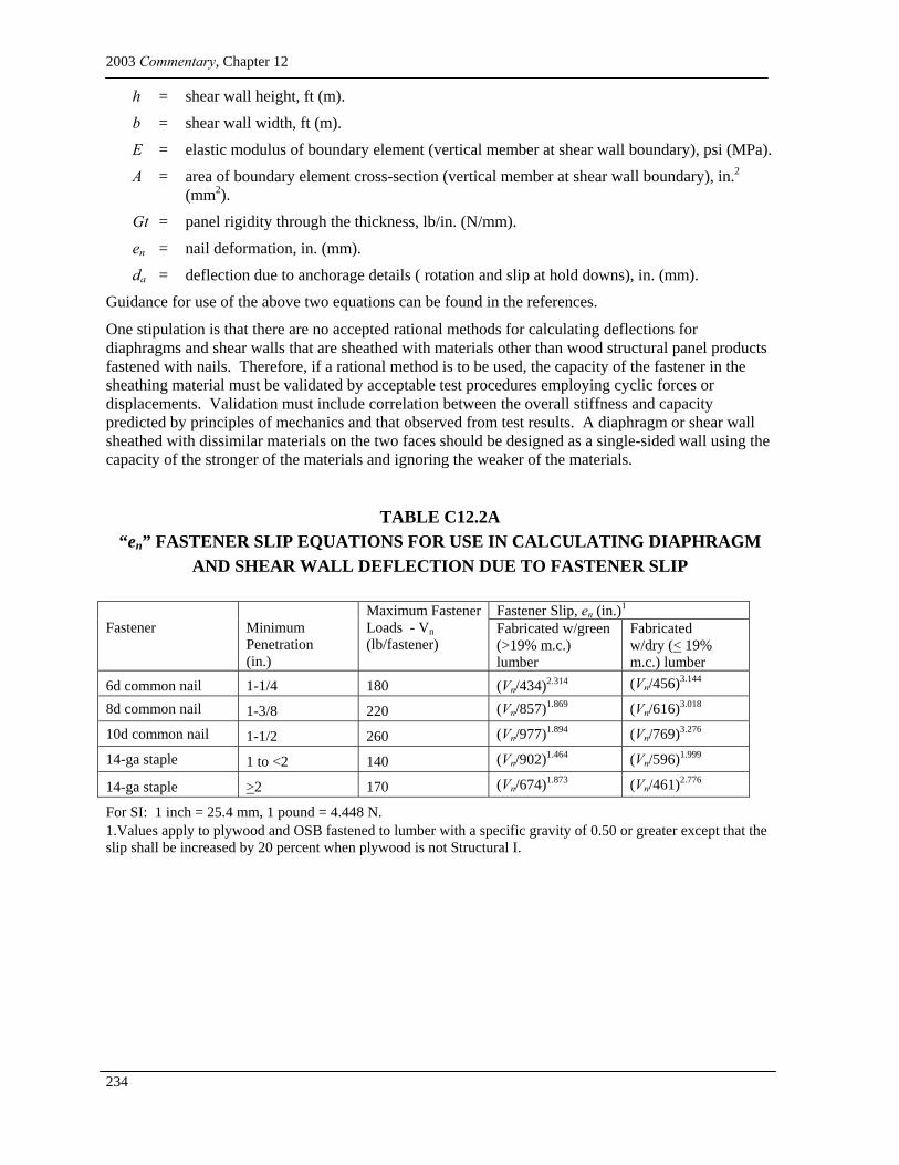
TABLE C12.2A “en” FASTENER SLIP EQUATIONS FOR USE IN CALCULATING DIAPHRAGM
AND SHEAR WALL DEFLECTION DUE TO FASTENER SLIP
Fastener Slip, en (in.)1 Fastener
Minimum Penetration (in.)
Maximum Fastener Loads - Vn (lb/fastener)
Fabricated w/green (>19% m.c.) lumber
Fabricated w/dry (< 19% m.c.) lumber
6d common nail 1-1/4 180 (Vn/434)2.314 (Vn/456)3.144
8d common nail 1-3/8 220 (Vn/857)1.869 (Vn/616)3.018
10d common nail 1-1/2 260 (Vn/977)1.894 (Vn/769)3.276
14-ga staple 1 to <2 140 (Vn/902)1.464 (Vn/596)1.999
14-ga staple >2 170 (Vn/674)1.873 (Vn/461)2.776
For SI: 1 inch = 25.4 mm, 1 pound = 4.448 N. 1.Values apply to plywood and OSB fastened to lumber with a specific gravity of 0.50 or greater except that the slip shall be increased by 20 percent when plywood is not Structural I.
Wood Structure Design Requirements
235
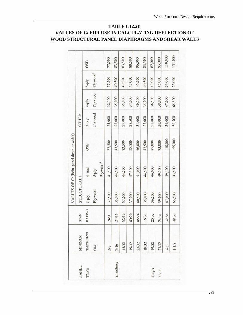
TABLE C12.2B VALUES OF Gt FOR USE IN CALCULATING DEFLECTION OF
WOOD STRUCTURAL PANEL DIAPHRAGMS AND SHEAR WALLS

2003 Commentary, Chapter 12
236
VALUES OF Gt (lb/in. panel depth or width)
STRUCTURAL I OTHER
PANEL
TYPE
Thickness
(in.) All Plywood Grades Marine All Other
Plywood
Grades
¼ 31,000 31,000 24,000
11/32 33,000 33,000 25,500
3/8 34,000 34,000 26,000
15/32 49,500 49,500 38,000
½ 50,000 50,000 38,500
19/32 63,500 63,500 49,000
5/8 64,500 64,500 49,500
23/32 65,500 65,500 50,500
¾ 66,500 66,500 51,000
7/8 68,500 68,500 52,500
1 95,500 95,500 73,500
Sanded
Plywood
1-1/8 97,500 97,500 75,000
For SI: 1 inch = 25.4 mm, 1 pound/inch of panel depth or width = 0.1751 N/mm. 1. Applies to plywood with 5 or more layers; for 5 ply/3 layer plywood, use values for 4 ply.
Effect of Green Lumber Framing on Diaphragms and Shear Walls: A recent study of wood structural panel shear walls (APA Report T2002-53) fabricated with wet lumber and tested when dry shows that shear stiffness is affected to a much larger degree than shear strength when compared to control specimens fabricated with dry lumber and tested when dry. The shear strength of walls fabricated with wet lumber showed negligible reductions (0-7 percent) when compared to control specimens. The shear stiffness of walls fabricated with wet lumber was always reduced when compared to control specimens. Observed reductions in stiffness were consistent with predicted stiffness reductions based on use of Eq. C12.2A and nail slip values specified in Table C12.2A. For example, measured deflection of a standard wall configuration at the shear wall factored unit shear value was approximately 2.5 times the deflection of the control specimen and predicted deflections were within 0.05 inches of the test deflection for both the fabricated wet specimen and control specimen.
As a result of these tests, direct consideration of shear wall stiffness is recommended in lieu of applying shear wall strength reductions when wood structural panel shear walls are fabricated with wet lumber (e.g. moisture content > 19 percent). To address reduced shear stiffness for shear walls fabricated with wet lumber, story drift calculations should be based on en values for lumber with moisture content > 19 percent to determine compliance with allowable story drift limits of the Provisions. A similar relationship can be expected when analyzing the deflection of diaphragms.
The designer should keep in mind that deflection equations are verified for walls with wood structural panel sheathing only and does not address the increased stiffness provided by finish materials such as gypsum and stucco. The CUREE-Caltech Woodframe project illustrated that finishes such as gypsum wallboard and stucco increase the stiffness of the walls. While these
Wood Structure Design Requirements
237
deflection equations are currently the best estimate of wood structural panel wall deflection, actual wall deflections will likely be less than predicted deflections due to the presence of finish materials in typical wall construction.
12.2.3.11 and 12.2.3.12. Tie-down devices should be based on cyclic tests of the connection to provide displacement capacity that allows rotation of the end post without significant reduction in the shear wall resistance. The tie-down device should be stronger than the lateral capacity of the wall so that the mechanism of failure is the sheathing fasteners and not a relatively brittle failure of the wall anchorage. For devices for which the published resistance is in allowable stress design values, the nominal strength shall be determined by multiplying the allowable design load by 1.3. The nominal strength of a tie-down device may be determined as the average maximum test load resisted without failing under cyclic loading. In that case, the average should be based on tests of at least three specimens.
Calculations of deflection of shear walls should include the effects of crushing under the compression chord, uplift of the tension chord, slip in the tie-down anchor with respect to the post, and shrinkage effects of the platforms, which primarily consist of floor framing members. Movement associated with these variables can be significant and neglecting their contribution to the lateral displacement of the wall will results in a significant under-estimation of the deflection. Custom tie-down devices are permitted to be designed using methods for the particular materials used and AF&PA/ASCE 16 under alternative means and methods.
Tie-down devices that permit significant vertical movement between the tie-down and the tie-down post can cause failure in the nails connecting the shear wall sheathing to the sill plate. High tension and tie-down rotation due to eccentricity can cause the bolts connecting the tie-down bracket to the tie-down post to pull through and split the tie-down post. Devices that permit such movement include heavily loaded, one-sided, bolted connections with small dimensions between elements resisting rotation due to eccentricity. Any device that uses over-drilled holes, such as most bolted connections, will also allow significant slip to occur between the device and the tie-down post before load is restrained. Both the NDS and the steel manual specify that bolt holes will be over-drilled as much as 1/16 in. (2 mm). This slip is what causes much of the damage to the nails connecting the sheathing to the sill plate. Friction between the tie-down post and the device cannot be counted on to resist load because relaxation in the wood will cause a loss of clamping and, therefore, a loss in friction over time. This is why all tests should be conducted with the bolts “finger tight” as opposed to tightening with a wrench.
Cyclic tests of tie-down connections must follow a pattern similar to the sequential phased displacement (SPD) tests used by Dolan (1996) and Rose (1996). These tests used full wall assemblies and therefore induced deflection patterns similar to those expected during an earthquake. If full wall assembly tests are not used to test the tie-down devices, it must be shown that the expected rotation as well as tension and compression are used. This is to ensure that walls using the devices will be able to deform in the intended manner. This allows the registered design professional to consider compatibility of deformations when designing the structure.
Splitting of the bottom plate of the shear walls has been observed in tests as well as in structures subjected to earthquakes. Splitting of plates remote from the end of the shear wall can be caused by the rotation of individual sheathing panels inducing upward forces in the nails at one end of the panel and downward forces at the other. With the upward forces on the nails and a significant distance perpendicular to the wall to the downward force produced by the anchor bolt, high cross-grain bending stresses occur. Splitting can be reduced or eliminated by use of large plate washers that are sufficiently stiff to reduce the eccentricity and by use of thicker sill plates. Thicker sill plates (3 in. nominal, 65 mm) are recommended for all shear walls for which Table 12.2-3a (or 12.2-3b) requires 3 in. nominal (65 mm) framing to prevent splitting due to close nail spacing. This is to help prevent failure of the sill plate due to high lateral loading and cross-grain bending.
2003 Commentary, Chapter 12
238
The tendency for the nut on a tie-down bracket anchor bolt to loosen significantly during cycled loading has been observed in some testing. One tested method of limiting the loosening is to apply adhesive between the nut and tie-down bolt.
A logical load path for the structure must be provided so that the forces induced in the upper portions of the structure are transmitted adequately through the lower portions of the structure to the foundation.
In the 2003 Provisions update cycle anchorage provisions were divided into two distinct subsections to separately address anchorage for uplift and anchorage for in-plane shear. The title section was clarified to address both traditional segmented shear walls and perforated shear walls.
A prior Provisions requirement that nuts on both uplift anchors and in-plane shear anchors be prevented from loosening prior to covering the framing, was deleted. This provision was originally based on observed backing-off of nuts in a small number of cyclic tests of shear walls but in the large number of tests conducted since that time this phenomenon has not been observed to occur. It was felt that retaining the existing requirement for tightening the nuts prior to closing in the framing was sufficient to address this issue.
A prior Provisions requirement for the nominal strength of a tiedown to be equal to or exceed the factored resistance of the shear wall times Ωo / 1.3, was replaced with simpler wording that has an equivalent effect and is intended primarily as a statement of design philosophy. The new language in Sec 12.2.3.11 only refers to the nominal strength of the tiedown and the nominal strength of the shear wall. Nominal strengths for typical nailed wood structural panel shear walls are set forth in Table 4.3A column B of AF&PA ASD/LRFD Supplement, Special Design Provisions for Wind and Seismic. In addition, similar language making the nominal strength of in-plane shear anchorage match the nominal strength values of the shear walls was added, to provide a basis for design of in-plane shear connections that is consistent with requirements for uplift anchorage. The capacity-based nominal strength have been introduced primarily as a statement of design philosophy, with the intent of forcing sheathing nailing to be the controlling failure mechanism. The complexity of load paths in wood frame buildings suggest that additional study is needed to achieve reliable development of desired failure mechanisms.
Plate washers are now specifically permitted to have a diagonal slot not exceeding 1-3/4 inches in length to facilitate placement within the width of the sill plate.
12.2.3.14 Sheathing nails should be driven flush with the surface of the panel, and not further. This could result in the nail head creating a small depression in, but not fracturing, the first veneer. This requirement is imposed because of the significant reduction in capacity and ductility observed in shear walls constructed with over-driven nails. It is advised that the edge distance for sheathing nails be increased as much as possible along the bottom of the panel to reduce the potential for the nails to pull through the sheathing.
12.3 GENERAL DESIGN REQUIREMENTS FOR ENGINEERED WOOD CONSTRUCTION Engineered construction for wood structures as defined by the Provisions encompasses all structures that cannot be classified as conventional construction. Therefore, any structure exceeding the height limitations or having braced walls spaced at intervals greater than those prescribed in Table 12.4-1 or not conforming to the requirements in Sec. 12.4 must be engineered using standard design methods and principles of mechanics. Framing members in engineered wood construction are sized based on calculated capacities to resist the loads and forces imposed. Construction techniques that utilize wood for lateral force resistance in the form of diaphragms or shear walls are discussed further in Sec. 12.4. Limitations have been set on the use of wood diaphragms that are used in combination with concrete and masonry walls or where torsion is induced by the arrangement of the vertical resisting elements. A load path must be provided to transmit the lateral forces from the diaphragm through the vertical resisting elements to the foundation. It is important for the registered
Wood Structure Design Requirements
239
design professional to follow the forces down, as for gravity loads, designing each connection and member along the load path.
Although wood moment resisting frames are not specifically covered in the Provisions, they are not excluded by them. There are several technical references for their design, and they have been used in Canada, Europe, and New Zealand. Wood moment resisting frames are designed to resist both vertical loads and lateral forces. Detailing at columns to beam/girder connections is critical in developing frame action and must incorporate effects of member shrinkage. Detailed information can be obtained from the national wood research laboratories. There are many references that describe the engineering practices and procedures used to design wood structures that will perform adequately when subjected to lateral forces. The list at the end of this Commentary chapter gives some, but by no means all, of these.
Deformation compatibility The registered design professional should visualize the deformed shape of the structure to ensure that the connections provide the necessary ductility to allow the probable deflection demand placed on the structure. Unlike steel or other metal structures, wood is not a ductile material and virtually all of the ductility achieved in the structure is in the connections. The planned failure mechanism of wood structures must be through the connections, including the nailing of structural panels; otherwise the failure will be brittle in nature. The philosophy of strong, elastic columns and yielding beams cannot be projected from steel to wood structures. To enable a wood structure to deform and dissipate energy during a seismic event, the connections must be the weak link in the structure and must be ductile. Recent earthquakes, such as that in Northridge, California, have shown failures due to the fact that consideration of deformation compatibility was neglected.
As an example of a compatibility issue, consider the deformation compatibility between a tie-down connector to the tie-down post and the edge nailing of shear wall sheathing to the tie-down post and adjacent bottom plate. Recent testing and observations from the Northridge earthquake have suggested that the tie-down post experiences notable displacement before significant load can be carried through the tie-down connector. This is due, among other things, to the oversizing of the bolt holes in the tie-down post and the deformation and rotation of the tie-down bracket. Anchor bolts connecting the bottom plate to the foundation below tend to attempt to carry the shear wall uplift as the tie-down post moves. The sheathing, however, is nailed to both the bottom plate, which is held in place, and the tie-down post, which is being pulled up. The result is a large deformation demand being placed on the nails connecting the sheathing to the framing. This often results in the nails pulling out of the sheathing at the tie-down post corner and sometimes results in an unzipping effect where a significant portion of the remaining sheathing nailing fails as high loads cause one nailed connection to fail and move on to overstress the next nail. The most effective solution currently known is to limit the slip and deformation at the tie-down post by using a very stiff nailed or screwed tie-down.
Because this is an area where understanding of compatibility issues is just starting to develop, the Sec. 12.3.2 provision uses the wording “shall be considered in design” in lieu of the originally proposed “provision shall be made to ensure…” The intent is to provide guidance while not requiring the impossible.
If necessary, the stiffness of the wood diaphragms and shear walls can be increased with the use of adhesives (if adhesives are to be used). However, it should be noted that there are no rational methods for determining deflections in diaphragms that are constructed with non-wood sheathing materials. If the nail stiffness values or shear stiffness of non-wood sheathing materials is determined in a scientific manner, such as through experimental cyclic testing, the calculations for determining the stiffness of shear panels will be considered validated.
2003 Commentary, Chapter 12
240
Limitation on forces contributed by concrete or masonry. Due to the significant difference in in-plane stiffness between wood and masonry or concrete systems, the use of wood members to resist the seismic forces produced by masonry and concrete is not allowed. This is due to the probable torsional response such a structure will exhibit. There are two exceptions where wood can be considered to be part of the seismic-load-resisting system. The first is where the wood is in the form of a horizontal truss or diaphragm and the lateral loads do not produce rotation of the horizontal member. The second exception is in structures of two stories or less in height. In this case, the capacity of the wood shear walls will be sufficient to resist the lower magnitude loads imposed. Five restrictions are imposed on these structures to ensure that the structural performance will not include rotational response and that the drift will not cause failure of the masonry or concrete portions of the structure.
Shearwalls and Diaphragms. Many wood-framed structures resist seismic forces by acting as a “box system.” The forces are transmitted through diaphragms, such as roofs and floors, to reactions provided by shear walls. The forces are, in turn, transmitted to the lower stories and to the final point of resistance, the foundations. A shear wall is a vertical diaphragm generally considered to act as a cantilever from the foundation.
A diaphragm is a nearly horizontal structural unit that acts as a deep beam or girder when flexible in comparison to its supports and as a plate when rigid in comparison to its supports. The analogy to a girder is somewhat more appropriate since girders and diaphragms are made up as assemblies (American Plywood Association, 1991; Applied Technology Council, 1981). Sheathing acts as the “web” to resist the shear in diaphragms and is stiffened by the framing members, which also provide support for gravity loads. Flexure is resisted by the edge elements acting like “flanges” to resist induced tension or compression forces. The “flanges” may be top plates, ledgers, bond beams, or any other continuous element at the perimeter of the diaphragm.
The “flange” (chord) can serve several functions at the same time, providing resistance to loads and forces from different sources. When it functions as the tension or compression flange of the “girder,” it is important that the connection to the “web” be designed to accomplish the shear transfer. Since most diaphragm “flanges” consist of many pieces, it is important that the splices be designed to transmit the tension or compression occurring at the location of the splice and to recognize that the direction of application of seismic forces can reverse. It should also be recognized that the shear walls parallel to the flanges may be acting with the flanges to distribute the diaphragm shears. When seismic forces are delivered at right angles to the direction considered previously, the “flange” becomes a part of the reaction system. It may function to transfer the diaphragm shear to the shear wall(s), either directly or as a drag strut between segments of shear walls that are not continuous along the length of the diaphragm.
For shear walls, which may be considered to be deep vertical cantilever beams, the “flanges” are subjected to tension and compression while the “webs” resist the shear. It is important that the “flange” members, splices at intermediate floors, and the connection to the foundation be detailed and sized for the induced forces.
The “webs” of diaphragms and shear walls often have openings. The transfer of forces around openings can be treated similarly to openings in the webs of steel girders. Members at the edges of openings have forces due to flexure and the higher web shear induced in them and the resultant forces must be transferred into the body of the diaphragm beyond the opening.
In the past, wood sheathed diaphragms have been considered to be flexible by many registered design professionals and model code enforcement agencies. The newer versions of the model codes now recognize that the determination of rigidity or flexibility for determination of how forces will be distributed is dependent on the relative deformations of the horizontal and vertical force-resisting elements. Wood sheathed diaphragms in structures with wood frame shear walls with various types of sheathing may be relatively rigid compared with the vertical resisting system and, therefore, capable of transmitting torsional lateral forces. A diaphragm is considered to be flexible if its
Wood Structure Design Requirements
241
deformation is two or more times that of the vertical force-resisting elements subjected to the same force.
Discussions of these and other topics related to diaphragm and shear wall design, such as cyclic testing and pitched or notched diaphragms, may be found in the references.
The capacity of shear walls must be determined either from tabulated values that are based on experimental results or from standard principles of mechanics. The tables of allowable values for shear walls sheathed with other than wood or wood-based structural-use panels were eliminated in the 1991 Provisions as a result of re-learning the lessons from past earthquakes and testing on the performance of structures sheathed with these materials during the Northridge earthquake. In the 1997 Provisions values for capacity for shear walls sheathed with wood structural panels were reduced from monotonic test values by 10 percent to account for the reduction in capacity observed during cyclic tests. This decision was reviewed for the 2000 edition of the Provisions due to the availability of an expanded data set of test results. The reduction was removed for the 2000 Provisions when the effect of the test loading protocol was determined to be the cause of the initial perceived reductions. Capacities for diaphragms were not reduced from the monotonic test values because the severe damage that occurred in shear walls has not been noted in diaphragms in recent earthquakes.
The Provisions are based on assemblies having energy dissipation capacities which were recognized in setting the R factors. For diaphragms and shear walls utilizing wood framing, the energy dissipation is almost entirely due to nail bending. Fasteners other than nails and staples have not been extensively tested under cyclic load application. When screws or adhesives have been tested in assemblies subjected to cyclic loading, they have had a brittle mode of failure. For this reason, adhesives are prohibited for wood framed shear wall assemblies in SDC C and higher and only the tabulated values for nailed or stapled sheathing are recommended. If one wished to use shear wall sheathing attached with adhesives, as an alternate method of construction in accordance with Sec. 1.1.2.5, caution should be used (Dolan and White, 1992; Foschi and Filiatrault, 1990). The increased stiffness will result in larger forces being attracted to the structure. The anchorage connections and adjoining assemblies must, therefore, be designed for these increased forces. Due to the brittle failure mode, these walls should be designed to remain elastic, similar to unreinforced masonry. The use of adhesives for attaching sheathing for diaphragms increases their stiffness, and could easily change the diaphragm response from flexible to rigid.
Horizontal distribution of shear. The Provisions define when a diaphragm can be considered to be flexible or rigid. The purpose is to determine whether the diaphragm should have the loads proportioned according to tributary area or stiffness. For flexible diaphragms, the loads should be distributed according to tributary area whereas for rigid diaphragms, the loads should be distributed according to stiffness.
The distribution of seismic forces to the vertical elements (shear walls) of the seismic-force-resisting system is dependent, first, on the stiffness of the vertical elements relative to that of the horizontal elements and, second, on the relative stiffness of the various vertical elements if they have varying deflection characteristics. The first issue is discussed in detail in the Provisions, which define when a diaphragm can be considered flexible or rigid and set limits on diaphragms that act in rotation or that cantilever. The second is largely an issue of engineering mechanics, but is discussed here because significant variations in engineering practice currently exist.
In situations where a series of vertical elements of the seismic-force-resisting system are aligned in a row, seismic forces will distribute to the different elements according to their relative stiffness.
Typical current design practice is to distribute seismic forces to a line of wood structural panel sheathed walls in proportion to the lengths of the wall segments such that each segment carries the same unit load. Wood structural panel sheathed wall segments without openings can generally be calculated to have a stiffness in proportion to the wall length when: the tie-down slip is ignored, the
2003 Commentary, Chapter 12
242
wood structural panel sheathing is selected from standard selection tables, and the aspect ratio limits of the Provisions are satisfied. For stiffness to be proportional to the wall length, the average load per nail for a given nail size must be approximately equal. Conversely, a wall could be stiffened by adding nails and reducing the calculated average load per nail. When including tie-down slip from anchors with negligible slip (1/16 in. [2 mm] or less), the assumption of wall stiffness proportional to length is still fairly reasonable. For larger tie-down slip values, wall stiffness will move towards being proportional to the square of the wall length; more importantly, however, the anchorage will start exhibiting displacement compatibility problems. For shear walls with aspect ratios higher than 2/1, the stiffness is no longer in proportion to the length and equations are not available to reasonably calculate the stiffness. For a line of walls with variations in tie-down slip, chord framing, unit load per nail, or other aspects of construction, distribution of load to wall segments will need to be based on a deflection analysis. The shear wall and diaphragm deflection equations that are currently available are not always accurate. As testing results become available, the deflection calculation formulas will need to be updated and design assumptions for distribution of forces reviewed.
Torsional diaphragm force distribution. A diaphragm is flexible when the maximum lateral deformation of the diaphragm is more than two times the average story drift. Conversely, a diaphragm will be considered rigid when the diaphragm deflection is equal to or less than two times the story drift. This is based on a model building code definition that applies to all materials.
For flexible diaphragms, seismic forces should be distributed to the vertical force-resisting elements according to tributary area or simple beam analysis. Although rotation of the diaphragm may occur because lines of vertical elements have different stiffness, the diaphragm is not considered stiff enough to redistribute seismic forces through rotation. The diaphragm can be visualized as a single-span beam supported on rigid supports.
For diaphragms defined as rigid, rotational or torsional behavior is expected and results in redistribution of shear to the vertical force-resisting elements. Requirements for horizontal shear distribution are in Sec. 5.2.4. Torsional response of a structure due to irregular stiffness at any level within the structure can be a potential cause of failure. As a result, dimensional and diaphragm ratio limitations are provided for different categories of rotation. Also, additional requirements apply when the structure is deemed to have a torsional irregularity in accordance with Table 4.3-2, Item 1a or 1b.
In order to understand limits placed on diaphragms acting in rotation, it is helpful to consider two different categories of diaphragms. Category I includes rigid diaphragms that rely on force transfer through rotation to maintain stability. An example would be an open front structure with shear walls on the other three sides. For this more structurally critical category, applicable limitations are:
Diaphragm may not be used to resist forces contributed by masonry or concrete in structures over one story.
The length of the diaphragm normal to the opening may not exceed 25 ft ( to perpendicular shear walls), and diaphragm L/b ratios are limited as noted.
Additional limitations apply when rotation is significant enough to be considered a torsional irregularity.
Category II includes rigid diaphragms that have two or more supporting shear walls in each of two perpendicular directions but, because the center of mass and center of rigidity do not coincide, redistribute forces to shear walls through rotation of the diaphragm. These can be further divided into Category IIA where the center of rigidity and mass are separated by a small portion of the structure’s least dimension and the magnitude of the rotation is on the order of the accidental rotation discussed in Sec. 5.2.4.2. For this level of rotation, an exception may result in no particular limitations being placed on diaphragm rotation for Category IIA. Category IIB, rigid diaphragms
Wood Structure Design Requirements
243
with eccentricities larger than those discussed in Sec. 5.2.4.2, are subject to the following limitations:
Diaphragm may not be used to resist forces contributed by masonry or concrete in structures over one story.
Additional limitations apply when rotation is significant enough to be considered a torsional irregularity.
Because flexible diaphragms have very little capacity for distributing torsional forces, further limitation of aspect ratios is used to limit diaphragm deformation such that rigid behavior will occur. The resulting deformation demand on the structure also is limited. Where diaphragm ratios are further limited, exceptions permit higher ratios where calculations demonstrate that higher diaphragm deflections can be tolerated. In this case, it is important to determine the effect of diaphragm rigidity on both the horizontal distribution and the ability of other structural elements to withstand resulting deformations.
Proposals to prohibit wood diaphragms acting in rotation were advanced following the 1994 Northridge earthquake. To date, however, the understanding is that the notable collapses in the Northridge earthquake occurred in part because of lack of deformation compatibility between the various vertical resisting elements rather than because of the inability of the diaphragm to act in rotation.
Diaphragm cantilever. Limitations concerning diaphragms that cantilever horizontally past the outermost shear wall (or other vertical element) are related to but distinct from those imposed because of diaphragm rotation. Such diaphragms can be flexible or rigid and for rigid diaphragms can be Category I, IIA or IIB. Both the limitations based on diaphragm rotation (if applicable) and the following limit on diaphragm cantilever must be considered:
Diaphragm cantilever may not exceed the lesser of 25 ft or two thirds of the diaphragm width.
Relative stiffness of vertical elements. In situations where a series of vertical elements of the seismic-force-resisting system are aligned in a row, the forces will distribute to the different elements according to their relative stiffnesses. This behavior needs to be taken into account whether it involves a series of wood structural panel shear walls of different lengths, a mixture of wood structural panel shear walls with diagonal lumber or non-wood sheathed shear walls, or a mixture of wood shear walls with walls of some other material such as concrete or masonry.
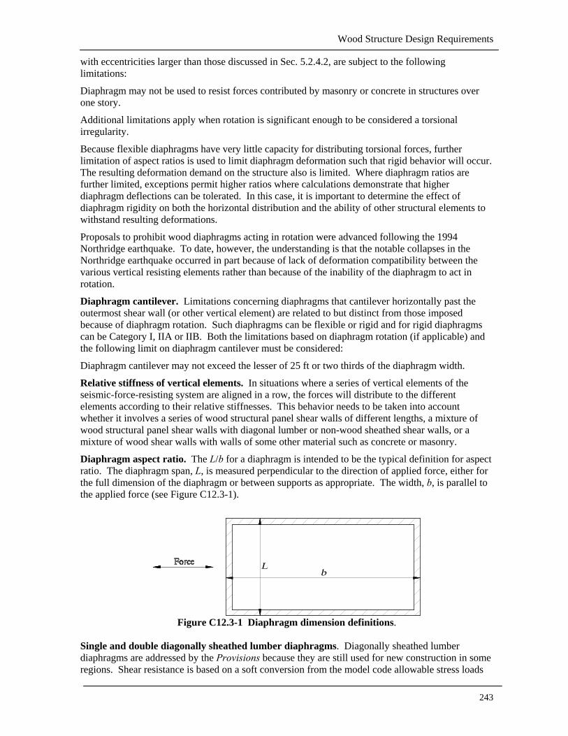
Diaphragm aspect ratio. The L/b for a diaphragm is intended to be the typical definition for aspect ratio. The diaphragm span, L, is measured perpendicular to the direction of applied force, either for the full dimension of the diaphragm or between supports as appropriate. The width, b, is parallel to the applied force (see Figure C12.3-1).
Figure C12.3-1 Diaphragm dimension definitions.
Single and double diagonally sheathed lumber diaphragms. Diagonally sheathed lumber diaphragms are addressed by the Provisions because they are still used for new construction in some regions. Shear resistance is based on a soft conversion from the model code allowable stress loads

2003 Commentary, Chapter 12
244
and capacities to Provisions strength loads for regions with high spectral accelerations. This will allow users in the western states, where this construction is currently being used, to continue with little or no change in requirements; at the same time, reasonable values are provided for regions with lower spectral
Shear wall aspect ratio. The h/b for a shear wall is intended to be the typical definitions for aspect ratio. The h of the shear wall is the clear story height (see Figure C12.3-2). The alternate definition of aspect ratio is only to be used where specific design and detailing is provided for force transfer around the openings. It is required that the individual wall piers meet the aspect ratio requirement (see Figure C12.3-3) and that the overall perforated wall also meet the aspect ratio requirement. Use of the alternate definition involves the design and detailing of chord and collector elements around the opening, and often results in the addition of blocking, strapping, and special nailing. As noted, the design for force transfer around the opening must use a rational analysis and be in accordance with AF&PA/ASCE 16, which discusses design principles for shear walls, diaphragms, and boundary elements.
In general, unit shear values for wood structural panel sheathing have been based on tests of shear wall panels with aspect ratios of 2/1 to 1/1. Narrower wall segments (that is, with aspect ratios greater than 2/1) have been a recent concern based on damage observations following the Northridge earthquake and based on results of recent research (Applied Technology Council, 1995; White and Dolan, 1996). In response, various limitations on aspect ratios have been proposed. In the Provisions, an aspect ratio adjustment, 2b/h, is provided to account for the reduced stiffness of narrow shear wall segments. This adjustment is based on a review of numerous tests of narrow aspect ratio walls by Technical Subcommittee 7. The maximum 3.5/1 aspect ratio is recommended based on constructability issues (placement of tie-downs) as well as reduced stiffness of narrower shear wall segments.
Figure C12.3-2 Typical shear wall height-to-width ratio.

Wood Structure Design Requirements
245
Figure C12.3-3 Alternate shear wall height-to-width ratio with design for force transfer around openings.
Single and double diagonally sheathed lumber shear walls. Diagonally sheathed lumber shear walls are addressed by the Provisions because they are still used for new construction in some regions. Resistance values are based on a soft conversion from the model code allowable stress loads and capacities to Provisions strength loads for regions with high spectral accelerations. This will allow users in the western states, where this construction is currently being used, to continue with little or no change in requirements; at the same time, reasonable values are provided for regions with lower spectral accelerations.
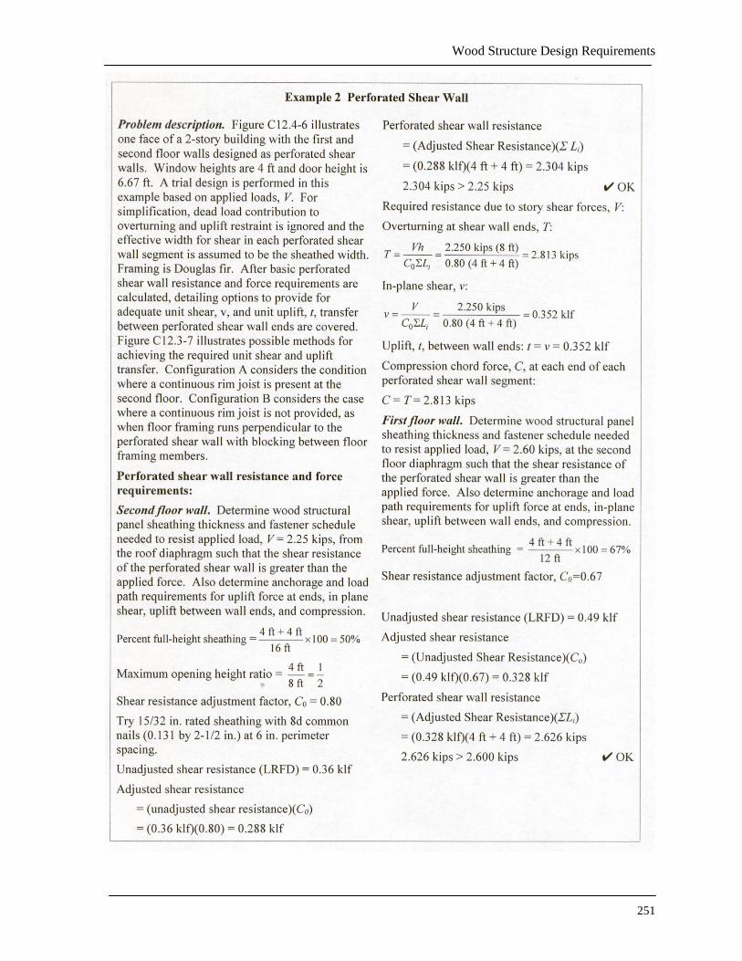
Perforated shear walls (PSW). In a traditional engineering approach for design of shear walls with openings, design force transfer around the openings involves developing a system of piers and coupling beams within the shear wall. Load paths for the shear and flexure developed in the piers and coupling beams generally require blocking and strapping extending from each corner of the opening to some distance beyond. This approach often results in shear wall detailing that is not practical to construct.
The perforated shear wall approach utilizes empirically based reductions of wood structural panel shear wall capacities to account for the presence of openings that have not been specifically designed and detailed for moment resistance. This method accounts for the capacity that is inherent in standard construction, rather than relying on special construction requirements. It is not expected that sheathed wall areas above and below openings behave as coupling beams acting end to end, but rather that they provide local restraint at their ends. As a consequence significantly reduced capacities are attributed to interior perforated shear wall segments with limited overturning restraint.
Example 1 and Example 2 provide guidance on the application of the perforated shear wall approach.

2003 Commentary, Chapter 12
246
Perforated Shear Wall Limitations. Perforated shear wall design provisions are applicable to wood structural panel shear walls having characteristics identified in this section.
1. The requirement that perforated shear wall segments be provided at each end of the perforated shear wall ensures that a minimum length of full height sheathing, conforming to applicable aspect ratio limits, is included at each end of a perforated shear wall.
2. A factored shear resistance not to exceed 0.64 klf, based on tabulated LRFD values, is provided to identify a point beyond which other means of shear wall design are likely to be more practical. Connection requirements associated with unadjusted shear resistance greater than 0.64 klf will likely not be practical as other methods of shear wall design will be more efficient.
3. Each perforated shear wall segment must satisfy the requirements for shear wall aspect ratios. The 2b/h adjustment for calculation of unadjusted factored shear resistance only applies when shear wall segments with h/b greater than 2:1 but not exceeding 3.5:1 are used in calculating perforated shear wall resistance. When shear wall segments with h/b greater than 2:1 are present in a perforated shear wall, but not utilized in calculation of perforated shear wall resistance, calculation of unadjusted factored shear resistance should not include the 2b/h adjustment. In many cases, due to the conservatism of the 2b/h adjustment, it is advantageous to simply ignore the presence of shear wall segments with h/b greater than 2:1 when calculating perforated shear wall resistance.
4. No out-of-plane offsets are permitted in a perforated shear wall. While the limit on out-of-plane offsets is not unique to perforated shear walls, it is intended to clearly indicate that a perforated shear wall shall not have out-of-plane (horizontal) offsets.
5. Collectors for shear transfer to each perforated shear wall segment provide for continuity between perforated shear wall segments. This is typically achieved through continuity of the wall double top plates or by attachment of perforated shear wall segments to a common load distributing element such as a floor or roof diaphragm.
6. Uniform top-of-wall and bottom-of-wall elevations are required for use of the empirical shear adjustment factors.
7. Limiting perforated shear wall height to 20 ft addresses practical considerations for use of the method as wall heights greater than 20 ft are uncommon.
a. The width, L, of a perforated shear wall and widths L1, L2 and L3 of perforated shear wall segments are shown in Figure C12.3-4. In accordance with the limitations and anchorage requirements, perforated shear wall segments and overturning restraint must be provided at each end of the perforated shear wall.
Perforated shear wall
L1 L2 L3
L
h
Overturning Restraint (each end) Figure C12.3-4 Perforated shear wall.
Wood Structure Design Requirements
247
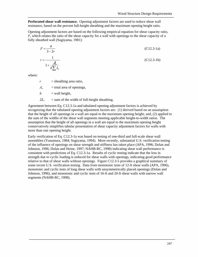
Perforated shear wall resistance. Opening adjustment factors are used to reduce shear wall resistance, based on the percent full-height sheathing and the maximum opening height ratio.
Opening adjustment factors are based on the following empirical equation for shear capacity ratio, F, which relates the ratio of the shear capacity for a wall with openings to the shear capacity of a fully sheathed wall (Sugiyama, 1981):
43 2
Fr
=−
(C12.3-1a)
1
1 o
i
r
h LA
=+∑
(C12.3-1b)
where:
r = sheathing area ratio,
Ao = total area of openings,
h = wall height,
ΣLi = sum of the width of full-height sheathing.
Agreement between Eq. C12.3-1a and tabulated opening adjustment factors is achieved by recognizing that the tabulated opening adjustment factors are: (1) derived based on an assumption that the height of all openings in a wall are equal to the maximum opening height; and, (2) applied to the sum of the widths of the shear wall segments meeting applicable height-to-width ratios. The assumption that the height of all openings in a wall are equal to the maximum opening height conservatively simplifies tabular presentation of shear capacity adjustment factors for walls with more than one opening height.
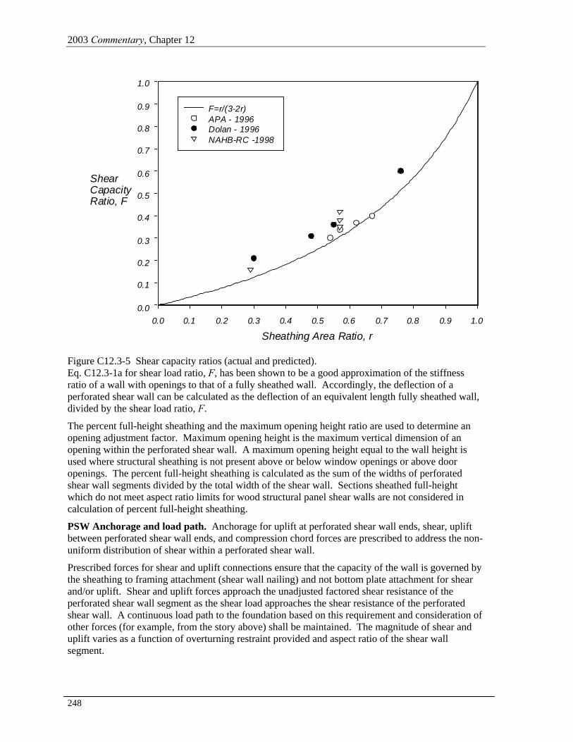
Early verification of Eq. C12.3-1a was based on testing of one-third and full-scale shear wall assemblies (Yasumura, 1984; Sugiyama, 1994). More recently, substantial U.S. verification testing of the influence of openings on shear strength and stiffness has taken place (APA, 1996; Dolan and Johnson, 1996; Dolan and Heine, 1997; NAHB-RC, 1998) indicating shear wall performance is consistent with predictions of Eq. C12.3-1a. Results of cyclic testing indicate that the loss in strength due to cyclic loading is reduced for shear walls with openings, indicating good performance relative to that of shear walls without openings. Figure C12.3-5 provides a graphical summary of some recent U.S. verification testing. Data from monotonic tests of 12-ft shear walls (APA, 1996), monotonic and cyclic tests of long shear walls with unsymmetrically placed openings (Dolan and Johnson, 1996), and monotonic and cyclic tests of 16-ft and 20-ft shear walls with narrow wall segments (NAHB-RC, 1998).
2003 Commentary, Chapter 12
248
Sheathing Area Ratio, r0.0 0.1 0.2 0.3 0.4 0.5 0.6 0.7 0.8 0.9 1.0
ShearCapacityRatio, F
0.0
0.1
0.2
0.3
0.4
0.5
0.6
0.7
0.8
0.9
1.0
F=r/(3-2r)APA - 1996Dolan - 1996NAHB-RC -1998
Figure C12.3-5 Shear capacity ratios (actual and predicted). Eq. C12.3-1a for shear load ratio, F, has been shown to be a good approximation of the stiffness ratio of a wall with openings to that of a fully sheathed wall. Accordingly, the deflection of a perforated shear wall can be calculated as the deflection of an equivalent length fully sheathed wall, divided by the shear load ratio, F.
The percent full-height sheathing and the maximum opening height ratio are used to determine an opening adjustment factor. Maximum opening height is the maximum vertical dimension of an opening within the perforated shear wall. A maximum opening height equal to the wall height is used where structural sheathing is not present above or below window openings or above door openings. The percent full-height sheathing is calculated as the sum of the widths of perforated shear wall segments divided by the total width of the shear wall. Sections sheathed full-height which do not meet aspect ratio limits for wood structural panel shear walls are not considered in calculation of percent full-height sheathing.
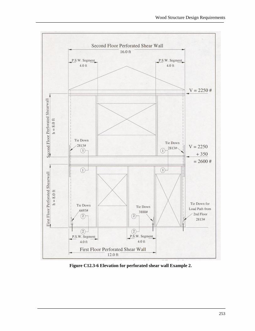
PSW Anchorage and load path. Anchorage for uplift at perforated shear wall ends, shear, uplift between perforated shear wall ends, and compression chord forces are prescribed to address the non-uniform distribution of shear within a perforated shear wall.
Prescribed forces for shear and uplift connections ensure that the capacity of the wall is governed by the sheathing to framing attachment (shear wall nailing) and not bottom plate attachment for shear and/or uplift. Shear and uplift forces approach the unadjusted factored shear resistance of the perforated shear wall segment as the shear load approaches the shear resistance of the perforated shear wall. A continuous load path to the foundation based on this requirement and consideration of other forces (for example, from the story above) shall be maintained. The magnitude of shear and uplift varies as a function of overturning restraint provided and aspect ratio of the shear wall segment.

Wood Structure Design Requirements
249
Uplift anchorage at perforated shear wall ends. Anchorage for uplift forces due to overturning are required at each end of the perforated shear wall. A continuous load path to the foundation based on this requirement and consideration of other forces (for example, from the story above) shall be maintained. In addition, compression chords of perforated shear wall segments are required to transmit compression forces equal to the required tension chord uplift force.
PSW Anchorage for in-plane shear. It is required that fastening be provided along the length of the sill plate of wall sections sheathed full-height to resist distributed shear, v, and uplift, t, forces. The resistance required for the shear connection is the average shear over the perforated shear wall segments, divided by the adjustment factor. This resistance will approach the unadjusted factored shear resistance of the wall as the shear wall demand approaches the maximum resistance. This shear fastening resistance conservatively accounts for the non-uniform distribution of shear within a perforated shear wall, since it represents the shear that can only be achieved when full overturning restraint is provided.
Provisions require that distributed fastening for shear, v, and uplift, t, be provided over the length of full-height sheathed wall sections. With no other specific requirements, the fastening between the full height segments will be controlled by minimum construction fastening requirements. For bottom plates on wood platforms this would only require one 16-penny nail at 16 in. on center. In some cases, it may be preferable to extend a single bottom plate fastening schedule across the entire length of the perforated shear wall rather than to require multiple fastening schedules.
Uplift anchorage between perforated shear wall ends. The resistance required for distributed uplift anchorage, t, is the same as the required shear resistance, v. The adequacy of the distributed uplift anchorage can be demonstrated using principles of mechanics and recent testing that determined the capacity of shear wall segments without uplift anchorage. A 4-ft wide shear wall segment with distributed anchorage of the base plate in lieu of an uplift anchor device provided about 25 percent of the resistance of a segment with uplift anchorage; an 8-ft wide shear wall segment resisted about 45 percent. When these are combined with the resistance adjustment factors, overturning resistance based on the unadjusted factored shear resistance is adequate for perforated shear wall segments with full height openings on each side. Conceptually the required distributed uplift resistance is intended to provide the same resistance that anchor bolts spaced at 2 ft on center provided for tested assemblies. While in the tested assemblies the bottom plates were fastened down, for design it is equally acceptable to fasten down the studs with a strap or similar device, since the studs will in turn restrain the bottom plate.
PSW Load path. A continuous load path to the foundation is required for the uplift resistance, T; the compression resistance, C; the unit shear resistance, v; and the unit uplift resistance, t. Consideration of accumulated forces (for example, from the stories above) is required. Where shear walls occur at the same location at each floor (stack), accumulation of forces is reasonably straightforward. Where shear walls do not stack, attention will need to be paid to maintaining a load path for tie-downs at each end of the perforated shear wall, for compression resistance at each end of each perforated shear wall segment, and for distributed forces v and t at each perforated shear wall segment. Where ends of shear perforated shear wall segments occur over beams or headers, the beam or header will need to be checked for the vertical tension and compression forces in addition to gravity forces. Where adequate collectors are provided at lower floor shear walls, the total shear wall load need only consider the average shear in the perforated shear wall segments above, and not the average shear divided by the adjustment factor.

2003 Commentary, Chapter 12
250
Wood Structure Design Requirements
251

2003 Commentary, Chapter 12
252
Wood Structure Design Requirements
253
Figure C12.3-6 Elevation for perforated shear wall Example 2.

2003 Commentary, Chapter 12
254
Figure C12.3-7 Details for perforated shear wall Example 2.
Wood Structure Design Requirements
255
12.3.1 Framing. All framing that is designed as part of an engineered wood structure must be designed with connectors that are able to transfer the required forces between various components. These connectors can be either proprietary hardware or some of the more conventional connections used in wood construction. However, these connectors should be designed according to accepted engineering practice to ensure that they will have the capacity to resist the forces. The requirement of columns and posts being framed to full end bearing requires that the force transfer from the column to the base be accomplished through end grain bearing of the wood, not through placing the bolts or other connectors in shear. This requirement is included to ensure adequate capacity for transfer of the vertical forces due to both gravity and overturning moment. Alternatively, the connection can be designed to transfer the full loading through placing the bolts or other connectors in shear neglecting all possible bearing.
The anchorage connections used in engineered wood construction must be capable of resisting the forces that will occur between adjacent members (beams and columns) and elements (diaphragms and shear walls). These connections can utilize proprietary hardware or be designed in accordance with principles of mechanics. Inadequate connections are often the cause of structural failures in wood structures, and the registered design professional is cautioned to use conservative values for allowable capacities since most published values are based on monotonic, not cyclic, load applications (U.S. Department of Agriculture, National Oceanic and Atmospheric Administration, 1971). Testing has shown that some one-sided bolted connections subject to cyclic loading, such as tie-down devices, do not perform well. This was substantiated by the poor performance of various wood frame elements in structures in the January 1994 Northridge earthquake.
Concrete or masonry wall anchorages using toe nails or nails subject to withdrawal are prohibited by the Provisions. It has been shown that these types of connections are inadequate and do not perform well (U.S. Department of Agriculture, National Oceanic and Atmospheric Administration, 1971). Ledgers subjected to cross-grain bending or tension perpendicular to grain also have performed poorly in past earthquakes, and their use is now prohibited by the Provisions.
12.4 CONVENTIONAL LIGHT-FRAME CONSTRUCTION The Provisions intend that a structure using conventional construction methods and complying with the requirements of this section be deemed capable of resisting the seismic forces imposed by the Provisions.
Repetitive framing members such as joists, rafters, and studs together with sheathing and finishes comprise conventional light-frame construction. The subject of conventional construction is addressed in each of the model codes. It is acknowledged and accepted that, for the most part, the conventional construction provisions in the model codes concerning framing members and sheathing that carry gravity loads are adequate. This is due to the fact that the tables in the model codes giving allowable spans have been developed using basic principles of mechanics. For seismic lateral force resistance, however, experience has shown that additional requirements are needed.
To provide lateral force resistance in vertical elements of structures, wall bracing requirements have been incorporated in conventional construction provisions of the model codes. With a few exceptions, these generally have been adequate for single family residences for which conventional construction requirements were originally developed. While the model building codes have been quite specific as to the type of bracing materials to be used and the amount of bracing required in any wall, no limits on the number or maximum separation between braced walls have been established. This section of the Provisions introduces the concept of mandating the maximum spacing of braced wall lines. By mandating the maximum spacing of braced wall lines and thereby limiting the lateral forces acting on these vertical elements, these revisions provide for a seismic-force-resisting system that will be less prone to overstressing and the requirements can be applied and enforced more uniformly than previous model building code requirements. While specific elements of light-frame construction may be calculated to be overstressed, there is typically a great deal of redundancy and uncounted resistance in such structures and they have generally performed well in past earthquakes. The experience in the

2003 Commentary, Chapter 12
256
Northridge earthquake was, however, less reassuring, especially for those residences relying on gypsum board or stucco for lateral force resistance. The light weight of conventional construction, together with the large energy dissipation capacity of the multiple fasteners used and inherent redundancy of the system are major factors in the observed good performance where wood or wood-based panels were used.
12.4.1 Limitations
12.4.1.1 General. The scope of this section specifically excludes prescriptive design of structures with concrete or masonry walls above the basement story, with the exception of veneer, in order to maintain the light weight of construction that the bracing requirements are based on. Wood braced wall panels and diaphragms as prescribed in this section are not intended to support lateral forces due to masonry or concrete construction. Prescriptive (empirical) design of masonry walls is allowed for in Chapter 11; however, design of structures combining masonry wall construction and wood roof and floor diaphragm construction must have an engineered design. In regions of high seismic activity, past earthquakes have demonstrated significant problems with structures combining masonry and wood construction. While engineered design requirements do address these problems, the prescriptive requirements in the model codes do not adequately address these problems. Masonry and concrete basement walls are permitted to be constructed in accordance with the requirements of the IRC.
12.4.1.2 Irregular structures. This section was added to the 1997 Provisions to clarify the definition of irregular (unusually shaped) structures that would require the structure to be designed for the forces prescribed in Chapter 5 in accordance with the requirements of Sec. 12.3 and 12.4. The descriptions and diagrams provide the registered design professional with several typical irregularities that produce torsional response, or result in forces considered high enough to require an engineered design and apply only to structures assigned to Seismic Design Category C or D.
Structures with geometric discontinuities in the lateral-force-resisting system have been observed to sustain more earthquake and wind damage than structures without discontinuities. They have also been observed to concentrate damage at the discontinuity location. For Seismic Design Categories C and D, this section translates applicable irregularities from Tables 4.3-2 and 4.3-3 into limitations on conventional light-frame construction. If the described irregularities apply to a given structure, it is required that either the entire structure or the non-conventional portions be engineered in accordance with the engineered design portions of the Provisions. The irregularities are based on similar model code requirements. While conceptually these are equally applicable to all seismic design categories, they are more readily accepted in areas of high seismic risk, where damage due to irregularities has been observed repeatedly.
Application of engineered design to non-conventional portions rather than to the entire structure is a common practice in some regions. The registered design professional is left to judge the extent of the portion to be designed. This often involves design of the nonconforming element, force transfer into the element, and a load path from the element to the foundation. A nonconforming portion will sometimes have enough of an impact on the behavior of a structure to warrant that the entire seismic-force-resisting system receives an engineered design.
12.4.1.2.1 Out-of-plane offset. This limitation is based on Item 4 of Table 4.3-2 and applies when braced wall panels are offset out-of-plane from floor to floor. In-plane offsets are discussed in another item. Ideally braced wall panels would always stack above of each other from floor to floor with the length stepping down at upper floors as less length of bracing is required.
Because cantilevers and set backs are very often incorporated into residential construction, the exception offers rules by which limited cantilevers and setbacks can be considered conventional. Floor joists are limited to 2 by 10 (actual: 12 by 93 in.; 38 by 235 mm) or larger and doubled at braced wall panel ends in order to accommodate the vertical overturning reactions at the end of braced wall panels. In addition the ends of cantilevers are attached to a common rim joist to allow for redistribution of load. For rim joists that cannot run the entire length of the cantilever, the metal tie is
Wood Structure Design Requirements
257
intended to transfer vertical shear as well as to provide a nominal tension tie. Limitations are placed on gravity loads to be carried by cantilever or setback floor joists so that the joist strength will not be exceeded. The roof loads discussed are based on the use of solid sawn members where allowable spans limit the possible loads. Where engineered framing members such as trusses are used, gravity load capacity of the cantilevered or setback floor joists should be carefully evaluated.
12.4.1.2.2 Unsupported diaphragm. This limitation is based in Item 1 of Table 4.3-2, and applies to open-front structures or portions of structures. The conventional construction bracing concept is based on using braced wall lines to divide a structure up into a series of boxes of limited dimension, with the seismic force to each box being limited by the size. The intent is that each box be supported by braced wall lines on all four sides, limiting the amount of torsion that can occur. The exception, which permits portions of roofs or floors to extend past the braced wall line, is intended to permit construction such as porch roofs and bay windows. Walls for which lateral resistance is neglected are allowed in areas where braced walls are not provided.
12.4.1.2.3 Opening in wall below. This limitation is based on Item 4 of Table 4.3-3 and applies when braced wall panels are offset in-plane. Ends of braced wall panels supported on window or door headers can be calculated to transfer large vertical reactions to headers that may not be of adequate size to resist these reactions. The exception permits a 1 ft extension of the braced wall panel over a 4 by 12 (actual: 32 by 113 in.; 89 by 286 mm) header on the basis that the vertical reaction is within a 45 degree line of the header support and therefore will not result in critical shear or flexure. All other header conditions require an engineered design. Walls for which lateral resistance is neglected are allowed in areas where braced walls are not provided.
12.4.1.2.4 Vertical offset in diaphragm. This limitation results from observation of damage that is somewhat unique to split-level wood frame construction. If floors on either side of an offset move in opposite directions due to earthquake or wind loading, the short bearing wall in the middle becomes unstable and vertical support for the upper joists can be lost, resulting in a collapse. If the vertical offset is limited to a dimension equal to or less than the joist depth, then a simple strap tie directly
connecting joists on different levels can be provided, eliminating the irregularity. The IRC, Sec. 502.6.1, provides requirements for tying of floor joists.
12.4.1.2.5 Non-perpendicular walls. This limitation is based on Item 5 of Table 4.3-2 and applies to nonperpendicular braced wall lines. When braced wall lines are not perpendicular to each other, further evaluation is needed to determine force distributions and required bracing.
12.4.1.2.6 Large diaphragm opening. This limitation is based on Item 3 of Table 4.3-2 and attempts to place a practical limit on openings in floors and roofs. Because stair openings are essential toresidential construction and have long been used without any report of life-safety hazards resulting, these are felt to be acceptable conventional construction. See Sec. 12.4.3.7 for detailing requirements for permitted openings.
12.4.1.2.7 Stepped foundation. This limits a condition that can cause a torsional irregularity per Item 1 of Table 4.3-2. Where heights of braced wall panels vary significantly, distribution of lateral forces will also vary. If a structure on a hill is supported on 2-ft-high, braced cripple wall panels on one side and 8-ft-high panels on the other, torsion and redistribution of forces will occur. An engineered design for this situation is required in order to evaluate force distribution and provide adequate wall bracing and anchor bolting. This limitation applies specifically to walls from the foundation to the floor. While gable-end walls have similar variations in wall heights, this has not been observed to be a significant concern in conventional construction. See Sec. 12.4.3.6 for detailing requirements for permitted foundation stepping.
12.4.2 Braced walls
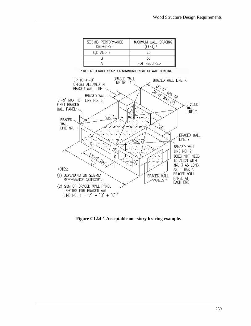
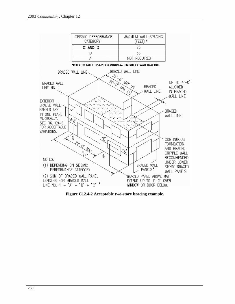
12.4.2.1 Spacing between braced wall lines. Table 12.4-1 prescribes the spacing of braced wall lines and number of stories permitted for conventional construction structures. Figures C12.4-1 and C12.4-

2003 Commentary, Chapter 12
258
2 illustrate the basic components of the lateral bracing system. Information in Tables 12.4-1 and 12.4-2 was first included in the 1991 Provisions.
12.4.2.2 Braced wall line sheathing. Table 12.4-2 prescribes the minimum length of bracing along each 25 ft (7.6 m) length of braced wall line. Total height of structures has been reduced to limit overturning of the braced walls so that significant uplift is not generally encountered. The height limit will accommodate 8 to 10 ft (2.4 to 3 m) story heights.
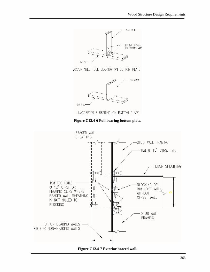
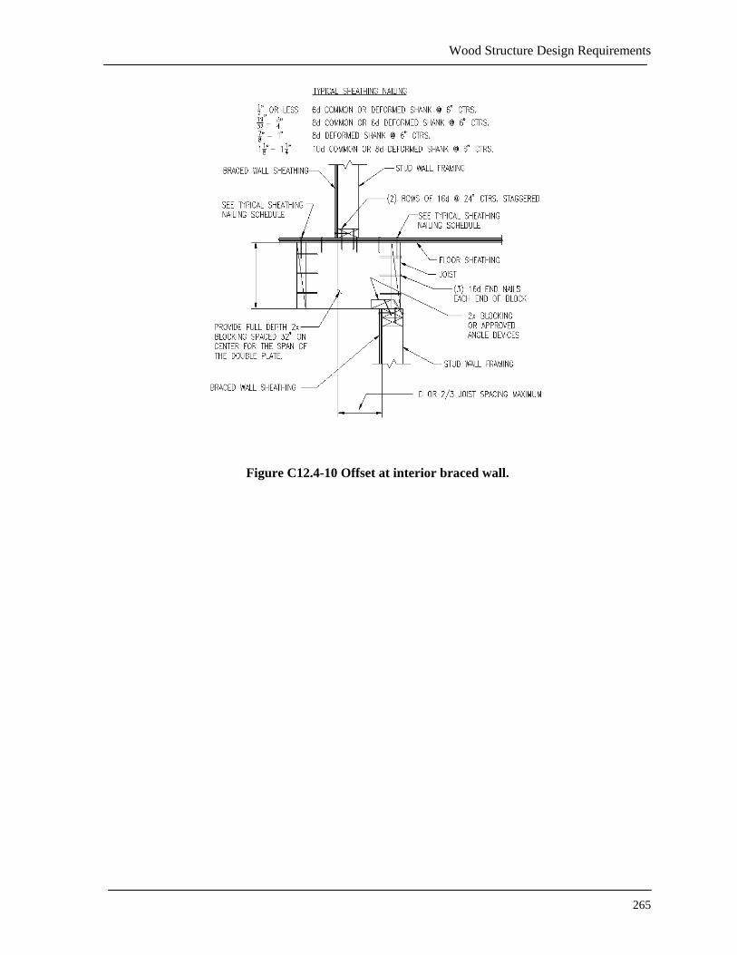
12.4.3 Detailing requirements. The intent of this section is to rely on the traditional light-frame conventional construction materials and fastenings as prescribed in the references for this chapter. Braced wall panels are not required to be aligned vertically or horizontally (within the limits prescribed in Sec. 12.4.1) but stacking is desirable where possible. With the freedom provided for non-alignment it becomes important that a load path be provided to transfer lateral forces from upper levels through intermediate vertical and horizontal resisting elements to the foundation. Connections between horizontal and vertical resisting elements are prescribed. In structures two or three stories in height, it is desirable to have interior braced wall panels supported on a continuous foundation. See Figures C12.4-3 through C12.4-13 for examples of connections.
The 1997 Provisions incorporated some of the wall anchorage, top plate, and braced wall panel connection requirements from the model building codes. These are included for completeness of the document and to clarify the requirement for the registered design professional. Additional requirements for foundations supporting braced wall panels has also been added to provide guidance and clarity for the registered design professional.
Wood Structure Design Requirements
259
Figure C12.4-1 Acceptable one-story bracing example.
2003 Commentary, Chapter 12
260
Figure C12.4-2 Acceptable two-story bracing example.

Wood Structure Design Requirements
261
Figure C12.4-3 Wall anchor detail.

2003 Commentary, Chapter 12
262
Figure C12.4-4 Double top splice.
Figure C12.4-5 Single top splice.
Wood Structure Design Requirements
263
Figure C12.4-6 Full bearing bottom plate.
Figure C12.4-7 Exterior braced wall.

2003 Commentary, Chapter 12
264
Figure C12.4-8 Interior braced wall at perpendicular joist.
Figure C12.4-9 Interior braced wall at parallel joist.
Wood Structure Design Requirements
265
Figure C12.4-10 Offset at interior braced wall.

2003 Commentary, Chapter 12
266
Figure C12.4-11 Diaphragm connection to braced wall below
Figure C12.4-12 Post base detail.
Wood Structure Design Requirements
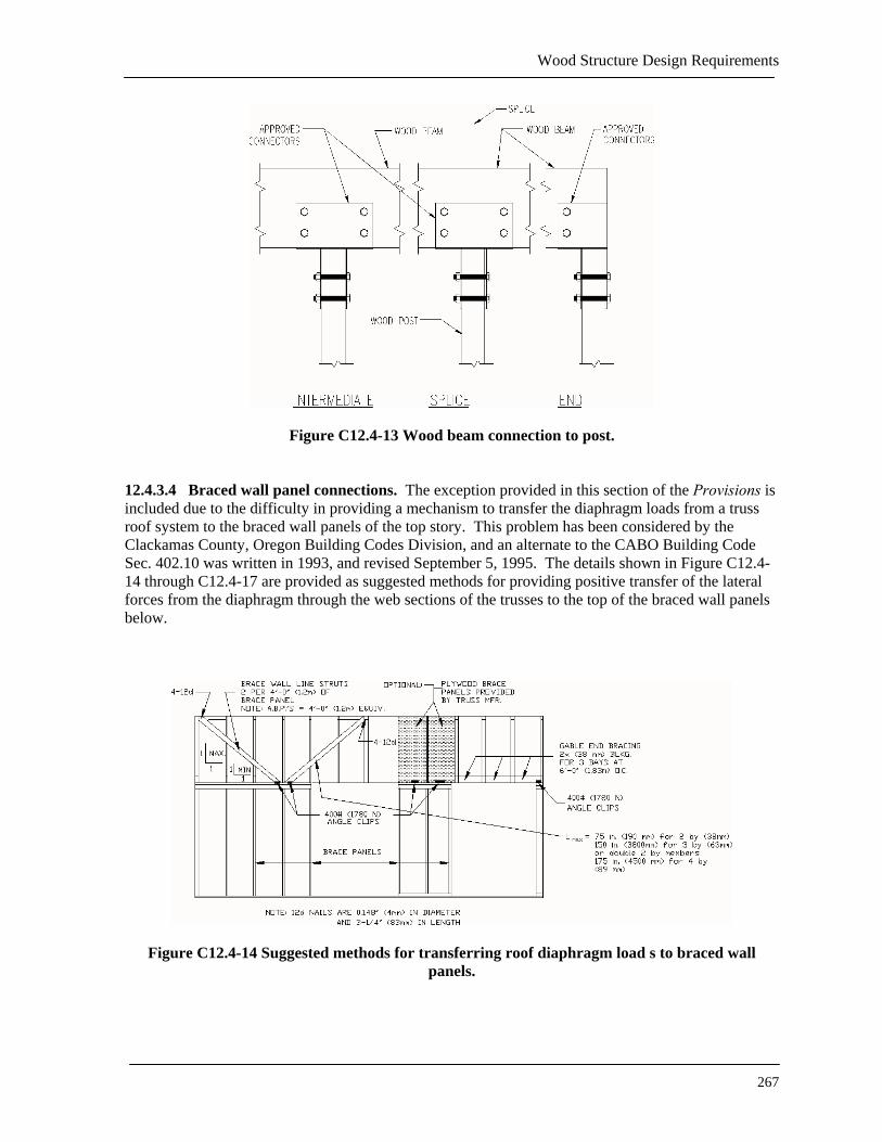
267
Figure C12.4-13 Wood beam connection to post.
12.4.3.4 Braced wall panel connections. The exception provided in this section of the Provisions is included due to the difficulty in providing a mechanism to transfer the diaphragm loads from a truss roof system to the braced wall panels of the top story. This problem has been considered by the Clackamas County, Oregon Building Codes Division, and an alternate to the CABO Building Code Sec. 402.10 was written in 1993, and revised September 5, 1995. The details shown in Figure C12.4-14 through C12.4-17 are provided as suggested methods for providing positive transfer of the lateral forces from the diaphragm through the web sections of the trusses to the top of the braced wall panels below.
Figure C12.4-14 Suggested methods for transferring roof diaphragm load s to braced wall panels.
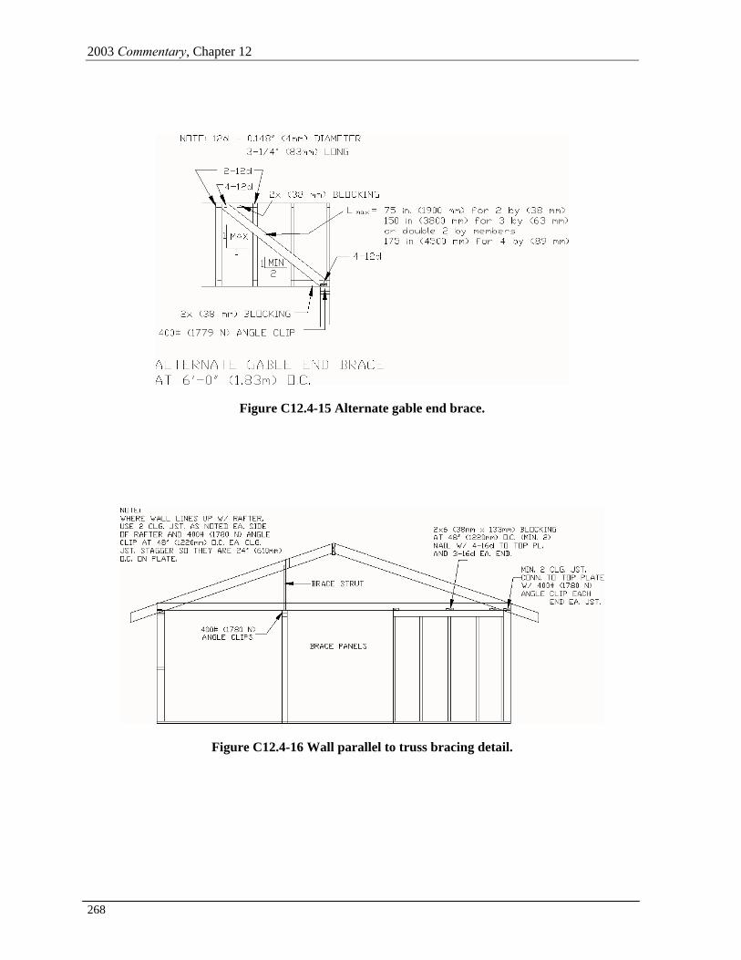
2003 Commentary, Chapter 12
268
Figure C12.4-15 Alternate gable end brace.
Figure C12.4-16 Wall parallel to truss bracing detail.
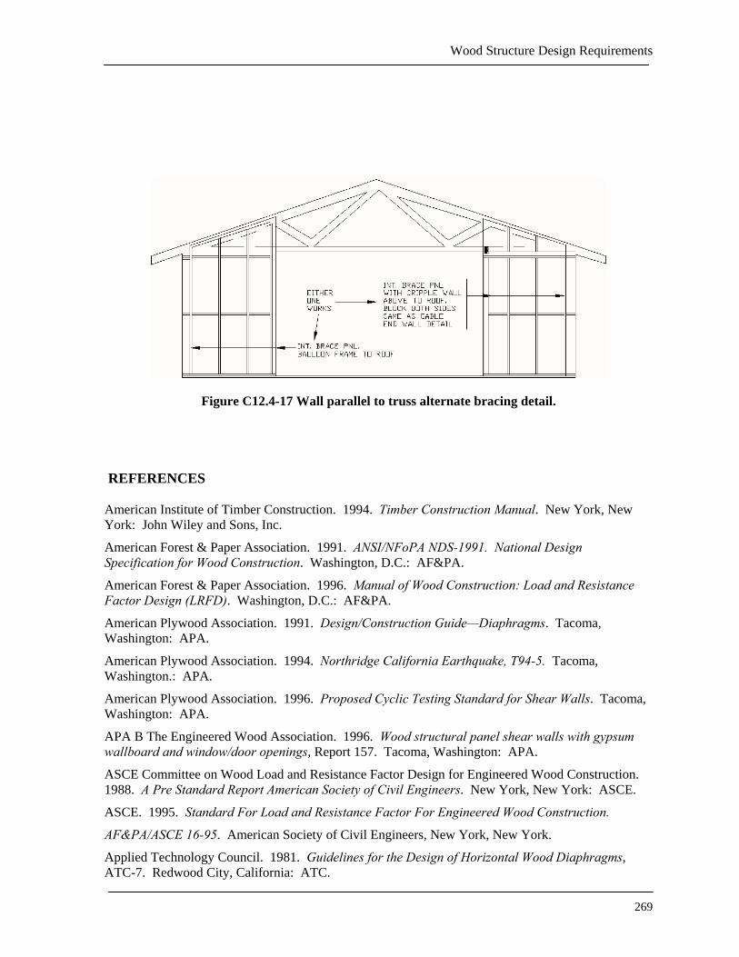
Wood Structure Design Requirements
269
Figure C12.4-17 Wall parallel to truss alternate bracing detail.
REFERENCES American Institute of Timber Construction. 1994. Timber Construction Manual. New York, New York: John Wiley and Sons, Inc.
American Forest & Paper Association. 1991. ANSI/NFoPA NDS-1991. National Design Specification for Wood Construction. Washington, D.C.: AF&PA.
American Forest & Paper Association. 1996. Manual of Wood Construction: Load and Resistance Factor Design (LRFD). Washington, D.C.: AF&PA.
American Plywood Association. 1991. Design/Construction Guide—Diaphragms. Tacoma, Washington: APA.
American Plywood Association. 1994. Northridge California Earthquake, T94-5. Tacoma, Washington.: APA.
American Plywood Association. 1996. Proposed Cyclic Testing Standard for Shear Walls. Tacoma, Washington: APA.
APA B The Engineered Wood Association. 1996. Wood structural panel shear walls with gypsum wallboard and window/door openings, Report 157. Tacoma, Washington: APA.
ASCE Committee on Wood Load and Resistance Factor Design for Engineered Wood Construction. 1988. A Pre Standard Report American Society of Civil Engineers. New York, New York: ASCE.
ASCE. 1995. Standard For Load and Resistance Factor For Engineered Wood Construction.
AF&PA/ASCE 16-95. American Society of Civil Engineers, New York, New York.
Applied Technology Council. 1981. Guidelines for the Design of Horizontal Wood Diaphragms, ATC-7. Redwood City, California: ATC.
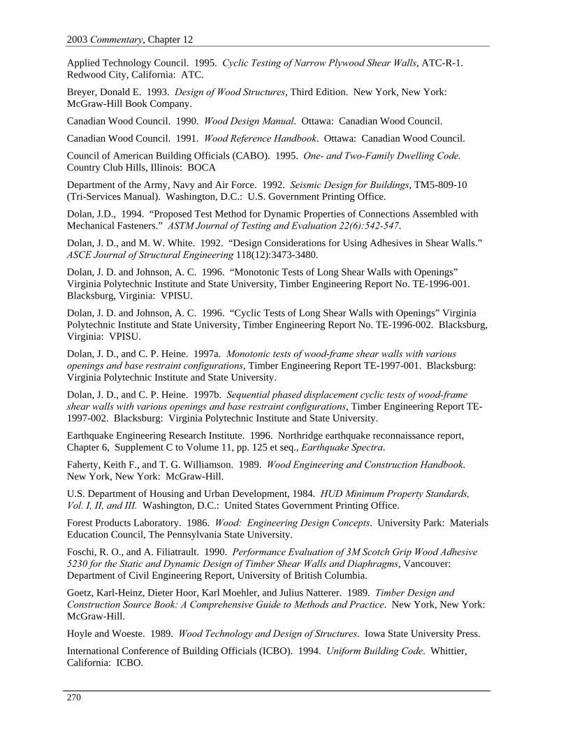
2003 Commentary, Chapter 12
270
Applied Technology Council. 1995. Cyclic Testing of Narrow Plywood Shear Walls, ATC-R-1. Redwood City, California: ATC.
Breyer, Donald E. 1993. Design of Wood Structures, Third Edition. New York, New York: McGraw-Hill Book Company.
Canadian Wood Council. 1990. Wood Design Manual. Ottawa: Canadian Wood Council.
Canadian Wood Council. 1991. Wood Reference Handbook. Ottawa: Canadian Wood Council.
Council of American Building Officials (CABO). 1995. One- and Two-Family Dwelling Code. Country Club Hills, Illinois: BOCA
Department of the Army, Navy and Air Force. 1992. Seismic Design for Buildings, TM5-809-10 (Tri-Services Manual). Washington, D.C.: U.S. Government Printing Office.
Dolan, J.D., 1994. “Proposed Test Method for Dynamic Properties of Connections Assembled with Mechanical Fasteners.” ASTM Journal of Testing and Evaluation 22(6):542-547.
Dolan, J. D., and M. W. White. 1992. “Design Considerations for Using Adhesives in Shear Walls.” ASCE Journal of Structural Engineering 118(12):3473-3480.
Dolan, J. D. and Johnson, A. C. 1996. “Monotonic Tests of Long Shear Walls with Openings” Virginia Polytechnic Institute and State University, Timber Engineering Report No. TE-1996-001. Blacksburg, Virginia: VPISU.
Dolan, J. D. and Johnson, A. C. 1996. “Cyclic Tests of Long Shear Walls with Openings” Virginia Polytechnic Institute and State University, Timber Engineering Report No. TE-1996-002. Blacksburg, Virginia: VPISU.
Dolan, J. D., and C. P. Heine. 1997a. Monotonic tests of wood-frame shear walls with various openings and base restraint configurations, Timber Engineering Report TE-1997-001. Blacksburg: Virginia Polytechnic Institute and State University.
Dolan, J. D., and C. P. Heine. 1997b. Sequential phased displacement cyclic tests of wood-frame shear walls with various openings and base restraint configurations, Timber Engineering Report TE-1997-002. Blacksburg: Virginia Polytechnic Institute and State University.
Earthquake Engineering Research Institute. 1996. Northridge earthquake reconnaissance report, Chapter 6, Supplement C to Volume 11, pp. 125 et seq., Earthquake Spectra.
Faherty, Keith F., and T. G. Williamson. 1989. Wood Engineering and Construction Handbook. New York, New York: McGraw-Hill.
U.S. Department of Housing and Urban Development, 1984. HUD Minimum Property Standards, Vol. I, II, and III. Washington, D.C.: United States Government Printing Office.
Forest Products Laboratory. 1986. Wood: Engineering Design Concepts. University Park: Materials Education Council, The Pennsylvania State University.
Foschi, R. O., and A. Filiatrault. 1990. Performance Evaluation of 3M Scotch Grip Wood Adhesive 5230 for the Static and Dynamic Design of Timber Shear Walls and Diaphragms, Vancouver: Department of Civil Engineering Report, University of British Columbia.
Goetz, Karl-Heinz, Dieter Hoor, Karl Moehler, and Julius Natterer. 1989. Timber Design and Construction Source Book: A Comprehensive Guide to Methods and Practice. New York, New York: McGraw-Hill.
Hoyle and Woeste. 1989. Wood Technology and Design of Structures. Iowa State University Press.
International Conference of Building Officials (ICBO). 1994. Uniform Building Code. Whittier, California: ICBO.
Wood Structure Design Requirements
271
Keenan, F. J. 1986. Limit States Design of Wood Structures. Morrison Hershfield Limited.
NAHB Research Center. 1998. The performance of shear walls with narrow wall segments, reduced based restraint, and alternative framing methods. Upper Marlboro, Maryland.
Rose, J. D., 1996. Research Report 158. “Preliminary Testing of Wood Structural Panel Shear Walls Under Cyclic (Reversed) Loading.” Tacoma, Washington: APA.
Sherwood and Stroh. 1989. “Wood-Frame House Construction” in Agricultural Handbook 73. Washington, D.C.: U.S. Government Printing Office.
Somayaji, Shan. 1992. Structural Wood Design. St. Paul, Minnesota: West Publishing Co.
Stalnaker, Judith J., and E. C. Harris. 1996. Structural Design in Wood, Second Edition. New York, New York: McGraw-Hill.
Sugiyama, H. 1981. “The evaluation of shear strength of plywood-sheathed walls with openings,” Wood Industry, 36-7, July.
Sugiyama, H., and T. Matsumoto. 1994. “Empirical equations for the estimation of racking strength of plywood-sheathed shear wall with openings,” in Summaries of Technical Papers of Annual Meeting, Architectural Institute of Japan, September.
U.S. Department of Agriculture, National Oceanic and Atmospheric Administration. 1971. San Fernando, California, Earthquake of February 9, 1971. Washington, D.C.: NOAA.
White, M. W. and J. D. Dolan, 1996. “Seismic Response of Timber Shear Walls. Part I: Aspect Ratios.” Paper submitted for publication in ASCE Journal of Structural Engineering.
Yasumura, M., and H. Sugiyama. 1984. “Shear properties of plywood-sheathed wall panels with openings,” in Transaction of the Architectural Institute of Japan, No. 338, April.
Additional references are listed in John Peterson. 1983. “Bibliography on Lumber and Wood Panel Diaphragms,” Journal of Structural Engineering, Vol. 109 No. 12. American Society of Civil Engineers, New York, New York.

2003 Commentary, Chapter 12
272
This page is intentionally left blank.