chapter 12(13) - wan technologies and routing route computation with a graph redundant routing...
TRANSCRIPT

Chapter 12(13) - WAN Technologies and Routing
Route computation with a graph Redundant routing information Default routes Building routing tables Computation of shortest path in a graph Weighted graph Synopsis of Djikstra's algorithm Distance metrics Dynamic route computation Distributed route computation Vector-distance algorithm Vector-distance algorithm (continued) Link-state routing Comparison Examples of WAN technology Summary
Introduction Characterizations of networks Differences between LAN and WAN Packet switches Connections to packet switches Packet switches as building blocks Store and forward Store and forward example Physical addressing in a WAN Next-hop forwarding Choosing next hop Source independence Hierarchical address and routing WAN architecture and capacity Routing in a WAN Modeling a WAN

Introduction
•LANs can be extended using techniques in previous chapter •Can not be extended arbitrarily far or to handle arbitrarily many computers
•Distance limitations even with extensions •Broadcast a problem
•Need other technologies for larger networks
Characterizations of networks
•Local Area Network (WAN) - single building •Metropolitan Area Network (MAN) - single city •Wide Area network (WAN) - country, continent, planet

Differences between LAN and WAN
•Satellite bridge can extend LAN across large distances •Still cannot accommodate arbitrarily many computers •WAN must be scalable to long distances and many computers

Packet switches
•To span long distances or many computers, network must replace shared medium with packet switches
•Each switch moves an entire packet from one connection to another •A small computer with network interfaces, memory and program dedicated to packet switching function

Connections to packet switches
•Packets switches may connect to computers and to other packet switches
Figure 13.1, Page 198
•Typically high speed connections to other packets switches, lower speed to computers •Technology details depend on desired speed

Packet switches as building blocks
•Packet switches can be linked together to form WANs
Page 199, Figure 13.2
•WANs need not be symmetric or have regular connections •Each switch may connect to one or more other switches and one or more computers

Store and forward
•Data delivery from one computer to another is accomplished through store-and-forward technology
•Packet switch stores incoming packet •... and forwards the packet to another switch or computer
•Packet switch has internal memory •Can hold packet if outgoing connection is busy •Packets for each connection held on queue

Physical addressing in a WAN
•Similar to LAN •Data transmitted in packets (equivalent to frames) •Each packet has format with header •Packet header includes destination and source addresses
•Many WANs use hierarchical addressing for efficiency •One part of address identifies destination switch •Other part of address identifies port on switch
Page 204 Figure 13.5

Next-hop forwarding
•Packet switch must choose outgoing connection for forwarding
•If destination is local computer, packet switch delivers computer port •If destination is attached another switch, this packet switch forwards to next hop through connection to another switch
•Choice based on destination address in packet

Choosing next hop
•Packet switch doesn't keep complete information about all possible destination •Just keeps next hop •So, for each packet, packet switch looks up destination in table and forwards through connection to next hop
Page 202, Figure 13.4

Source independence
•Next hop to destination does not depend on source of packet •Called source independence •Allows fast, efficient routing •Packet switch need not have complete information, just next hop
•Reduces total information •Increases dynamic robustness - network can continue to function even if topology changes without notifying entire network
Hierarchical address and routing
•Process of forwarding is called routing •Information is kept in routing table •Note that many entries have same next hop
Page 205, Figure 13.7
•In particular, all destinations on same switch have same next hop •Thus, routing table can be collapsed:
Page 206, Figure 13.8

WAN architecture and capacity
•More computers == more traffic •Can add capacity to WAN by adding more links and packet switches •Packet switches need not have computers attached •Interior switch - no attached computers •Exterior switch - attached computers

Routing in a WAN
•Both interior and exterior switches: •Forward packets •Need routing tables
•Must have: •Universal routing - next hop for each possible destination •Optimal routes - next hop in table must be on shortest path to destination

Modeling a WAN
•Use a graph: •Nodes model switches •Edges model direct connections between switches
•Captures essence of network, ignoring attached computers
Page 205, Figure 13.7
Route computation with a graph
•Can represent routing table with edges:
Figure 13.6, Page 205
•Graph algorithms can be applied to find routes

Redundant routing information
•Notice duplication of information in routing table for node 1:
Page 205, Figure 13.7
•Switch 1 has only one outgoing connection; all traffic must traverse that connection

Default routes
•Can collapse routing table entries with a default route •If destination does not have an explicit routing table entry, use use the default route:
Page 206, Figure 13.8
•Use of default route is optional (see node 3)
Building routing tables
•How to enter information into routing tables: •Manual entry - initialization file •Dynamically - through runtime interface
•How to compute routing table information: •Static routing - at boot time •Dynamic routing - allow automatic updates by a program
•Static is simpler; doesn't accommodate changes to network topology •Dynamic requires additional protocols; can work around network failures

Computation of shortest path in a graph
•Assume graph representation of network at each node •Use Djikstra's algorithm to compute shortest path from each node to every other node •Extract next-hop information from resulting path information •Insert next-hop information into routing tables

Weighted graph
•Djikstra's algorithm can accommodate weights on edges in graph •Shortest path is then the path with lowest total weight (sum of weights of all edges) •Shortest path not necessarily fewest edges (or hops)
Page 208, Figure 13.9

Synopsis of Djikstra's algorithm
•Keep data structure with list of nodes and weights of paths to those nodes •Use infinity to represent a node in the set S of nodes for which a path has not yet been computed •At each iteration, find a node in S, compute the path to that node, and delete the node from S
Distance metrics
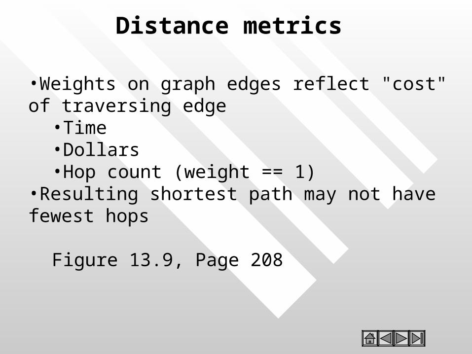
•Weights on graph edges reflect "cost" of traversing edge •Time •Dollars •Hop count (weight == 1)
•Resulting shortest path may not have fewest hops
Figure 13.9, Page 208

Dynamic route computation
•Network topology may change dynamically •Switches may be added •Connections may fail •Costs for connections may change
•Switches must update routing tables based on topology changes

Distributed route computation
•Pass information about network topology between nodes •Update information periodically •Each node recomputes shortest paths and next hops •Inject changes into routing tables

Vector-distance algorithm
•Local information is next-hop routing table and distance from each switch •Switches periodically broadcast topology information •Other switches update routing table based on received information

Vector-distance algorithm (continued)
•In more detail: •Wait for next update message •Iterate through entries in message •If entry has shorter path to destination:
•Insert source as next hop to destination •Record distance as distance from next hop to destination PLUS
•distance from this switch to next hop

Link-state routing
•Separates network topology from route computation •Switches send link-state information about local connections •Each switch builds own routing tables
•Uses link-state information to update global topology •Runs Djikstra's algorithm

Comparison
•Vector-distance algorithm •Very simple to implement •May have convergence problems •Used in RIP
•Link-state algorithm •Much more complex •Switches perform independent computations •Used in OSPF
Examples of WAN technology
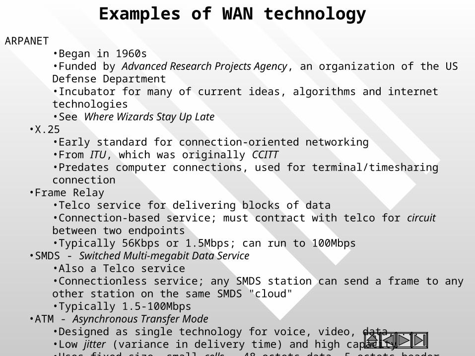
ARPANET •Began in 1960s •Funded by Advanced Research Projects Agency, an organization of the US Defense Department •Incubator for many of current ideas, algorithms and internet technologies •See Where Wizards Stay Up Late
•X.25 •Early standard for connection-oriented networking •From ITU, which was originally CCITT •Predates computer connections, used for terminal/timesharing connection
•Frame Relay •Telco service for delivering blocks of data •Connection-based service; must contract with telco for circuit between two endpoints •Typically 56Kbps or 1.5Mbps; can run to 100Mbps
•SMDS - Switched Multi-megabit Data Service •Also a Telco service •Connectionless service; any SMDS station can send a frame to any other station on the same SMDS "cloud" •Typically 1.5-100Mbps
•ATM - Asynchronous Transfer Mode •Designed as single technology for voice, video, data, ... •Low jitter (variance in delivery time) and high capacity •Uses fixed size, small cells - 48 octets data, 5 octets header •Can connect multiple ATM switches into a network

Summary
•WAN can span arbitrary distances and interconnect arbitrarily many computers •Uses packet switches and point-to-point connections •Packets switches use store-and-forward and routing tables to deliver packets to destination •WANs use hierarchical addressing •Graph algorithms can be used to compute routing tables •Many LAN technologies exist
Chapter 14 - Protocols and Layering
Techniques for reliable network communication Out-of-order delivery Duplicate delivery Lost packets Retransmission Replay Flow control Stop-and-go flow control Sliding window Example of sliding window Comparison of stop-and-go and sliding window Transmission times Network congestion Aoviding and recovering from network congestion Art, engineering and protocol design Summary
Introduction Why network software? Why protocols? One or many protocols? Protocol suites Layered protocol design The ISO 7-layer reference model The layers in the ISO model Layered software implementation Layered software and stacks Layering principle Messages and protocol stacks Protocol headers Control packets
Introduction
•LAN/WAN hardware can't solve all computer communication problems •Software for LAN and WAN systems is large and complicated •Layering is a structuring technique to organize networking software design and implementation

Why network software?
•Sending data through raw hardware is awkward and inconvenient - doesn't match programming paradigms well •Equivalent to accessing files by making calls to disk controller to position read/write head and accessing individual sectors •May not be able to send data to every destination of interest without other assistance •Network software provides high-level interface to applications

Why protocols?
•Name is derived from the Greek protokollen, the index to a scroll •Diplomats use rules, called protocols, as guides to formal interactions •A network protocol or computer communication protocol is a set of rules that specify the format and meaning of messages exchanged between computers across a network
•Format is sometimes called syntax •Meaning is sometimes called semantics
•Protocols are implemented by protocol software
One or many protocols?
•Computer communication across a network is a very hard problem •Complexity requires multiple protocols, each of which manages a part of the problem •May be simple or complex; must all work together
Protocol suites
•A set of related protocols that are designed for compatibility is called a protocol suite •Protocol suite designers:
•Analyze communication problem •Divide problems into sub-problems •Design a protocol for each sub-problem
•A well-designed protocol suite •Is efficient and effective - solves the problem without redundancy and makes best use of network capacity •Allows replacement of individual protocols without changes to other protocols

Layered protocol design
•Layering model is a solution to the problem of complexity in network protocols •Model suggests dividing the network protocol into layers, each of which solves part of the network communication problem •These layers have several constraints, which ease the design problem •Network protocol designed to have a protocol or protocols for each layer

The ISO 7-layer reference model
•International Organization for Standards (ISO) defined a 7-layer reference model as a guide to the design of a network protocol suite
Page 249, Figure 16.1
•Layers are named and numbered; reference to ``layer n'' often means the nth layer of the ISO 7-layer reference model

The layers in the ISO model
Caveat - many modern protocols do not exactly fit the ISO model, and the ISO protocol suite is mostly of historic interest
•Concepts are still largely useful and terminology persists
Layer 7: Application Application-specific protocols such as FTP and SMTP (electronic mail)
Layer 6: Presentation Common formats for representation of data
Layer 5: Session Management of sessions such as login to a remote computer
Layer 4: Transport Reliable delivery of data between computers
Layer 3: Network Address assignment and data delivery across a physical network
Layer 2: Data Link Format of data in frames and delivery of frames through network interface
Layer 1: Physical Basic network hardware - such as RS-232 or Ethernet

Layered software implementation
•Software implemented from layered design has layered organization •Software modules can be viewed as:
Page 252, Figure 16.2

Layered software and stacks •Related modules from previous figure are called a protocol stack or simply a stack •Two constraints:
•The software for each layer depends only on the services of the software provided by lower layers •The software at layer n at the destination receives exactly the same protocol message sent by layer n at the sender
•These constraints mean that protocols can be tested independently and can be replaced within a protocol stack

Layering principle
Page 256, Figure 16.5
Messages and protocol stacks
•On the sender, each layer: •Accepts an outgoing message from the layer above •Adds a header and other processing •Passes resulting message to next lower layer
•On the receiver, each layer: •Receives an incoming message from the layer below •Removes the header for that layer and performs other processing •Passes the resulting message to the next higher layer

Protocol headers
•The software at each layer communicates with the corresponding layer through information stored in headers •Each layer adds its header to the front of the message from the next higher layer •Headers are nested at the front of the message as the message traverses the network
Page 254, Figure 16.4

Control packets
•Protocol layers often need to communicate directly without exchanging data
•Acknowledge incoming data •Request next data packet
•Layers use control packets •Generated by layer n on sender •Interpreted by layer n on receiver •Transmitted like any other packet by layers n-1 and below
Techniques for reliable network communication
•Model - reliable delivery of a block of data from one computer to another
•Data values unchanged •Data in order •No missing data •No duplicated data
•Example - parity bit, checksum and CRC used to ensure data is unchanged

Out-of-order delivery
•Packets may be delivered out of order - especially in systems that include multiple networks •Out of order delivery can be detected and corrected through sequencing
•Sender attaches sequence number to each outgoing packet •Received uses sequence numbers to put packets in order and detect missing packets

Duplicate delivery
•Packets may be duplicated during transmission •Sequencing can be used to...
•Detect duplicate packets with duplicated sequence numbers •Discard those duplicate packets

Lost packets
•Perhaps the most widespread problem is lost packets •Any error - bit error, incorrect length - causes receiver to discard packet •Tough problem to solve - how does the receiver decide when a packet has been lost?
Retransmission •Protocols use positive acknowledgment with retransmission to detect and correct lost packets
•Receiver sends short message acknowledging receipt of packets •Sender infers lost packets from missing acknowledgments •Sender retransmits lost packets
•Sender sets timer for each outgoing packet •Saves copy of packet •If timer expires before acknowledgment is received, sender can retransmit saved copy
•Protocols define upper bound on retransmission to detect unrecoverable network failure

Replay
•Sufficiently delayed packets may be inserted into later sessions •Suppose two computers exchange data with packets numbered 1 to 5 •Packet 4 encounters an extraordinary delay; computers use retransmission to deliver valid copy of packet 4 •Two computers exchange data later on with packets numbered 1 to 10 •Initial `packet 4' can arrive during second session, so that the data from that old packet (rather than the current `packet 4' is inserted into the data •Protocols attach session number to each packet in a protocol session to differentiate packets from different sessions

Flow control
•Data overrun can occur when sender transmits data faster than receiver can process incoming data •Protocols use flow control mechanisms through which receiver can control rate of data transmission
•Stop-and-go •Sliding window

Stop-and-go flow control
•Receiver sends small control packet when it is ready for next packet •Sender waits for control packet before sending next packet •Can be very inefficient of network bandwidth if delivery time is large

Sliding window
•Allows sender to transmit multiple packets before receiving an acknowledgment •Number of packets that can be sent is defined by the protocol and called the window •As acknowledgments arrive from the receiver, the window is moved along the data packets; hence ``sliding window''

Example of sliding window
Page 260, Figure 16.6

Comparison of stop-and-go and sliding window
Page 261, Figure 16.7

Transmission times
•For stop-and-go, each packet takes 2L time to deliver (where L is the latency, or network delivery time) •Sliding window can improve by number of packets in window:
Tw = Tg * W (Tw is sliding window throughput, Tg is stop-and-
go throughput •Transmission time also limited by network transmission rate:
Tw = min(B, Tg * W) (B is maximum network bandwidth)
Network congestion
•Network congestion arises in network systems that include multiple links •If input to some link exceeds maximum bandwidth, packets will queue up at connection to that link
Page 262, Figure 16.8
•Eventually, packets will be discarded and packets will be retransmitted •Ultimately, network will experience congestion collapse •Problem related to, but not identical to, data overrun

Avoiding and recovering from network congestion
•Protocols attempt to avoid congestion and recover from network collapse by monitoring the state of the network and taking appropriate action •Can use two techniques:
•Notification from packet switches •Infer congestion from packet loss
•Packet loss can be used to detect congestion because modern networks are reliable and rarely lose packets through hardware failure •Sender can infer congestion from packet loss through missing acknowledgments •Rate or percentage of lost packets can be used to gauge degree of congestion
Art, engineering and protocol design
•Protocol design mixes engineering and art •There are well-known techniques for solving specific problems •Those techniques interact in subtle ways •Resulting protocol suite must account for interaction
•Efficiency, effectiveness, economy must all be balanced

Summary
•Layering is a technique for guiding protocol design and implementation •Protocols are grouped together into related protocol suites •A collection of layered protocols is called a protocol stack •Protocols use a variety of techniques for reliable delivery of data