chapter 13 wireless intraocular microrobots: opportunities
TRANSCRIPT

Chapter 13
Wireless Intraocular Microrobots:
Opportunities and Challenges
Olgac Ergeneman, Christos Bergeles, Michael P. Kummer,
Jake J. Abbott, and Bradley J. Nelson
Abstract Many current and proposed retinal procedures are at the limits of human
performance and perception. Microrobots that can navigate the fluid in the interior
of the eye have the potential to revolutionize the way the most difficult retinal
procedures are conducted. Microrobots are typically envisioned as miniature
mechatronic systems that utilize MEMS technology to incorporate sensing and
actuation onboard. This chapter presents a simpler alternative approach for the
development of intraocular microrobots consisting of magnetic platforms and
functional coatings. Luminescence dyes immobilized in coatings can be excited
and read wirelessly to detect analytes or physical properties. Drug coatings can be
used for diffusion-based delivery, and may provide more efficient therapy than
microsystems containing pumps, as diffusion dominates over advection at the
microscale. Oxygen sensing for diagnosis and drug therapy for retinal vein occlu-
sions are presented as example applications. Accurate sensing and therapy requires
precise control to guide the microrobot in the interior of the human eye. We require
an understanding of the possibilities and limitations in wireless magnetic control.
We also require the ability to visually track and localize the microrobot inside the
eye, while obtaining clinically useful retinal images. Each of these topics is
discussed.
Keywords Eye � Microrobot � Minimally invasive surgery � Magnetic control
� Wireless � Tracking � Localizing � Ophthalmoscopy � Intraocular � Luminescence
� Coatings � Drug delivery � Drug release � Sensing
O. Ergeneman (*)
Institute of Robotics and Intelligent Systems, ETH Zurich, Tannenstr. 3, CLA H 17.1,
8092 Zurich, Switzerland
e-mail: [email protected]
J. Rosen et al. (eds.), Surgical Robotics: Systems Applications and Visions,DOI 10.1007/978-1-4419-1126-1_13, # Springer Science+Business Media, LLC 2011
271
13.1 Introduction
During the past decade, the popularity of minimally invasive medical diagnosis and
treatment has risen remarkably. Further advances in biomicrorobotics will enable
the development of new diagnostic and therapeutic systems that provide major
advantages over existing methods. Microrobots that can navigate bodily fluids will
enable localized sensing and targeted drug delivery in parts of the body that are
currently inaccessible or too invasive to access.
Microelectromechanical systems (MEMS) technology has enabled the integra-
tion of sensors, actuators, and electronics at microscales. In recent years, a great
deal of progress has been made in the development of microdevices, and many
devices have been proposed for different applications. However, placing these
systems in a living body is limited by factors like biocompatibility, fouling, electric
hazard, energy supply, and heat dissipation. In addition, the development of
functional MEMS devices remains a time-consuming and costly process. Moving
microsized objects in a fluid environment is also challenging, and a great deal of
research has considered the development of microactuators for the locomotion of
microrobots. However, to date the most promising methods for microrobot loco-
motion have utilized magnetic fields for wireless power and control, and this topic
is now well understood [2, 28, 32, 49, 66]. A large number of micropumps have
been developed for drug delivery, but as size is reduced diffusion begins to
dominate over advection, making transport mechanisms behave differently at
small scales. Consequently, future biomedical microrobots may differ from what
is typically envisioned.
In this chapter we focus on intraocular microrobots. Many current and proposed
retinal procedures are at limits of human performance and perception. Microrobots
that can navigate the fluid in the interior of the eye have the potential to revolution-
ize the way the most difficult retinal procedures are conducted. The proposed
devices can be inserted in the eye through a small incision in the sclera, and control
within the eye can be accomplished via applied magnetic fields. In this chapter we
consider three topics in the design and control of intraocular microrobots: First, we
discuss functional coatings – both for remote sensing and targeted drug delivery.
Next, we discuss magnetic control, and the ability to generate sufficient forces to
puncture retinal veins. Finally, we discuss visually tracking and localizing intraoc-
ular microrobots. The eye is unique in that it is possible to observe the vasculature
and visually track the microrobot through the pupil.
Throughout this chapter, we consider the assembled-MEMS microrobots as
shown in Fig. 13.1, but the conclusions extend to other microrobot designs. Fabri-
cating truly 3-D mechanical structures at the microscale is challenging. With
current MEMS fabrication methods, mechanical parts are built using 2-D (planar)
geometries with desired thickness. Three-dimensional structures can be obtained by
bending or assembling these planar parts, and it has been demonstrated that very
complex structures can be built with such methods [33, 59, 65, 66]. The philosophy
of designing simple structures with no actuation or intelligence onboard begs the
272 O. Ergeneman et al.

question: Are these devices microrobots? It may be more accurate to think of these
devices as end-effectors of novel manipulators where magnetic fields replace
mechanical links, sensing is performed wirelessly, and system intelligence is
located outside of the patient. However, this matter of semantics is inconsequential
if the goal is to develop functional biomedical microdevices.
13.2 Functionalizing Microrobots with Surface Coatings
We present an alternative approach for the development of biomicrorobots utilizing
a magnetic platform and functional coatings for remote sensing and targeted drug
delivery (Fig. 13.2). Coatings possessing sensor properties or carrying drugs may be
superior to more complicated electromechanical systems. Luminescence dyes
immobilized in coatings can be excited and read out wirelessly for detecting
analytes or physical properties. Drugs coated on a carrier can be used for diffu-
sion-based delivery and may provide more efficient therapy than microsystems
containing pumps. Because of the discrepancy in scaling of volume and surface
area, reservoirs built inside microfabricated devices may be insufficient, whereas
surface coatings alone may provide sufficient volume. Fabrication of devices
utilizing coatings will also be simple compared to systems with many electrical
or mechanical components. All of these properties make wireless microrobots
consisting of magnetic bodies and functional coatings feasible in the near term.
13.2.1 Biocompatibility Coatings
Magnetic microrobots contain nickel, cobalt, iron, or their alloys. These elements
and their alloys are declared to be non-biocompatible. Hence, they are not used in
Fig. 13.1 Relatively simple 2-D parts can be assembled into complex 3-D structures (#IEEE
2008), reprinted with permission. The parts shown have dimensions 2.0mm � 1.0mm � 42mmand can be further miniaturized
13 Wireless Intraocular Microrobots: Opportunities and Challenges 273

medical devices. Ti and Ti-alloys are used extensively in biomedical applications
because of their excellent combination of biocompatibility, corrosion resistance,
and structural properties [51]. In order to achieve biocompatibility without sacrifi-
cing the magnetic properties, microrobot pieces can be coated with a thin layer of
Ti, forming a titanium dioxide layer once exposed to air.
In [17] microrobot pieces made of Ni are coated by Ti with thicknesses of
100 nm, 200 nm, 300 nm, and 500 nm using a DC sputterer. Biocompatibility covers
a broad spectrum of non-toxic and non-allergic properties, with various levels of
biocompatibility associated with the purpose of a medical device. Biocompatibility
tests involve toxicity tests, corrosion tests, and allergy tests. To validate the quality
of coatings, against possible faults and crack formations, in vitro direct-contact cell-
toxicity tests, in line with ISO 10993-5 8.3 standard, were performed on coated and
uncoated microrobots using NIH 3T3 fibroblast cells. Results show that as thin as a
100-nm-thick Ti coating is sufficient to obtain biocompatibility.
13.2.2 Coatings for Remote Sensing
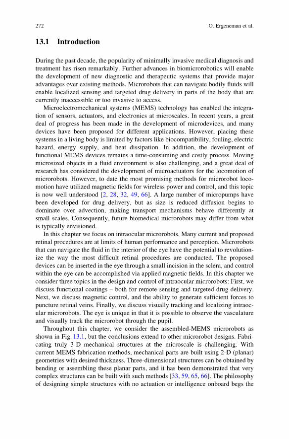
Surface coatings can be used to fabricate minimally invasive wireless sensor devices,
such as the intraocular sensor depicted in Fig. 13.3. The proposed device consists of a
luminescence sensor film that is integrated with a magnetically controlled platform.
This system can be used to obtain concentration maps of clinically relevant species
(e.g., oxygen, glucose, urea, drugs) or physiological parameters (e.g., pressure, pH,
temperature) inside the eye, specifically in the preretinal area. Effects of specific
physiological conditions on ophthalmic disorders can be conveyed.
These devices can also be used in the study of pharmacokinetics as well as in the
development of new drug delivery mechanisms, as summarized below [48].
Fig. 13.2 Microrobot utilizing a
functional coating (#IEEE 2008),
reprinted with permission. Right:A bare magnetic microrobot made
of thin assembled nickel pieces,
based on [66]. Left: A microrobot
coated with an oxygen-sensitive
film
274 O. Ergeneman et al.
The study of pharmacokinetics of drugs that diffuse into the eye following intraocular
drug injection requires analysis of ocular specimens as they change in time. The risk of
iatrogenic complications when penetrating into the ocular cavity with a needle has
restricted ocular pharmacokinetic studies on animals and humans. Microdialysis has
become an importantmethod for obtaining intraocular pharmacokinetic data and it has
reduced the number of animals needed to estimate ocular pharmacokinetic parameter
values. However, the insertion of the probe and anesthesia have been shown to alter
the pharmacokinetics of drugs. The microrobotic system presented here can replace
microdialysis probes for obtaining intraocular pharmacokinetic data as it provides a
minimally invasive alternative for in vivo measurements of certain analytes. Concen-
tration as a function of time and position can be obtained by steering the magnetic
sensor inside the vitreous cavity. Knowledge of concentration variations within the
vitreous will expedite the optimization of drug administration techniques for posterior
segment diseases.
13.2.2.1 Luminescence Sensing
Photoluminescence is the emission of electromagnetic radiation (i.e. photons) from a
material in response toabsorptionofphotons.The intensity and the lifetimeofemission
can be decreased by a variety of processes referred to as luminescence quenching.
Cornea
Iris
Lens
Sensor
VitreousHumor
AqueousHumor
Retina
Short Pass Filter Long Pass Filter
Blue LED Photodiode
Sclera
hnexc hnems
Fig. 13.3 Artist’s conception of the
magnetically controlled wireless
sensor in the eye (#IEEE 2008),
reprinted with permission [21]
13 Wireless Intraocular Microrobots: Opportunities and Challenges 275

Optical luminescence sensors work based on quenching of luminescence in the pres-
ence of a quencher (i.e., analyte of interest); the decrease in luminescence is related to
the quantity of the quencher. A number of devices using this principle have been
demonstrated and the basic principles of different methods can be found in [40]. The
quenching of luminescence is described by Stern-Volmer equations:
I0I¼ 1þ K½Q� (13.1)
t0t¼ 1þ K½Q� (13.2)
where I0 and I are the luminescence intensities in the absence and in the presence of
quencher, respectively, t0 and t are the luminescence lifetimes in the absence and
presence of quencher, respectively, [Q] is the quencher concentration, and K is the
Stern-Volmer quenching constant whose units are the reciprocal of the units of [Q].Luminescence dyes with high quantum yield, large dynamic range, and large
Stokes shift are preferred for luminescence sensors. To be used as a sensor, these
dyes need to be immobilized. They are usually bound to transparent and quencher-
permeable supporting matrices such as polymers, silica gels, or sol-gels. Quencher
permeability, selectivity, and the luminophore solubility are the important factors
for choosing appropriate supporting matrices.
Luminescence sensing can be done either based on luminescence intensity or
luminescence lifetime. The main difference between the two methods is that
intensity is an extrinsic property whereas lifetime is an intrinsic property. Extrinsic
techniques depend on parameters such as the dye concentration, optical surface
quality, photo-bleaching, and incidence angle, which change from sample to sam-
ple. When the sensor’s position changes, the optical path distance (OPD) from the
light source to the sensor and back to the photo detector changes. The total amount
of light collected by the sensor changes depending on the OPD and orientation.
These quantities are hard to control in such a wireless sensor application, limiting
the accuracy of this technique. Intrinsic properties do not depend on the parameters
described above, making lifetime measurements more promising for wireless
microrobotic applications.
There are two methods that are used for measuring luminescence lifetimes: time-
domain measurements and frequency-domain measurements. In time-domain mea-
surements the sample is excited with light pulses, and the intensity signal that
changes as a function of time is measured and analyzed. In frequency-domain
measurements the sample is excited with a periodic signal that consequently causes
a modulated luminescence emission at the identical frequency. Because of the
lifetime of emission, the emission signal has a phase shift with respect to the
excitation signal. The input excitation signal is used as a reference to establish a
zero-phase position and the lifetime is obtained by measuring the phase shift
between the excitation and emission signals.
276 O. Ergeneman et al.

13.2.2.2 An Intraocular Oxygen Sensor
The retina needs sufficient supply of oxygen and other nutrients to perform its
primary visual function. Inadequate oxygen supply (i.e. retinal hypoxia) is corre-
lated with major eye diseases including diabetic retinopathy, glaucoma, retinopathy
of prematurity, age-related macular degeneration, and retinal vein occlusions [25].
Retinal hypoxia is presumed to initiate angiogenesis, which is a major cause of
blindness in developed countries [14]. Attempts to test this hypothesis suffer from
the current methods of highly invasive oxygen electrodes. Hypoxia is typically
present at the end stages of retinal diseases. However, during the early stages, the
relation between blood flow sufficiency, vessel patency, and tissue hypoxia are still
unknown [55]. The influence of oxygen on these diseases is not well understood and
the ability to make long-term, non-invasive, in vivo oxygen measurements in the
human eye is essential for better diagnosis and treatment. Measuring the oxygen
tensions both in aqueous humor and vitreous humor, and particularly in the pre-
retinal area, is of great interest in ophthalmic research.
To address these issues, an intraocular optical oxygen sensor utilizing a lumi-
nescence coating has been developed [21]. The sensor works based on quenching of
luminescence in the presence of oxygen. A novel iridium phosphorescent complex
is designed and synthesized to be used as the oxygen probe. The main advantages of
this iridium complex, when compared to other metal complexes, are its higher
luminescence quantum yield, higher photo-stability, longer lifetime, stronger
absorption band in the visible region, and larger Stokes shift. Polystyrene is chosen
as the supporting matrix because of its high oxygen permeability and biocompatible
nature. The microrobots are dip-coated with polystyrene film containing lumines-
cence dye, and good uniformity is achieved across the magnetic body. Biocompati-
bility tests must still be performed on the polystyrene film with embedded dye.
If needed, an additional layer of pure polystyrene could be added to isolate the
sensing layer.
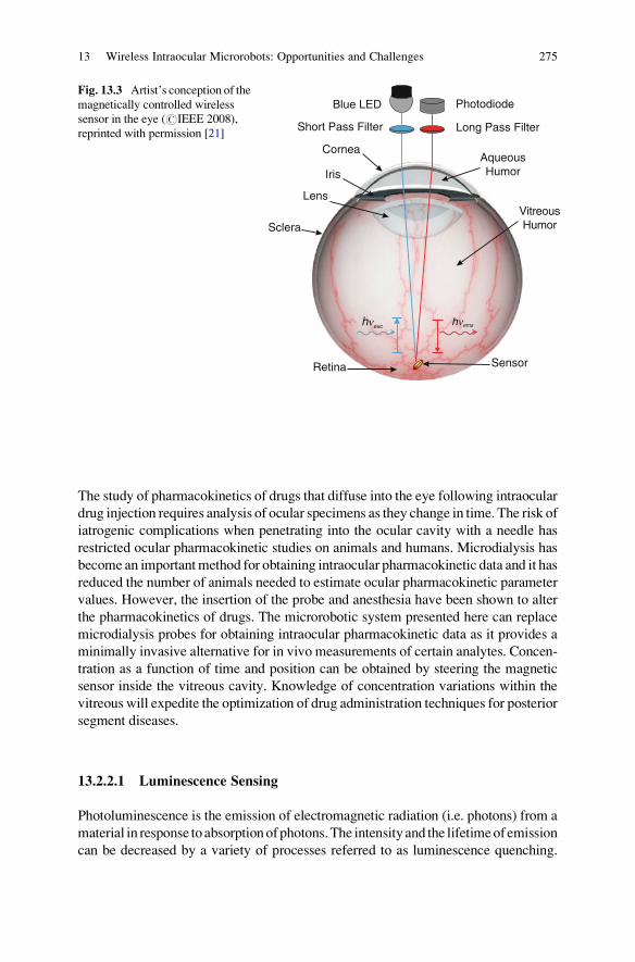
An experimental setup has been built to characterize the oxygen sensitivity of
the sensor. The details of the sensor and characterization setup can be found in [21].
A blue LED is used as the excitation source for the oxygen sensor system and
a photodiode is used to detect the luminescence. Optical filters are used to separate
the emission signal from the excitation signal. The frequency-domain lifetime
measurement approach is used in this work. De-ionized water is used for the
dissolved oxygen measurements. The sensor’s location in the setup is maintained
with a magnet. The distances between the components and the sensor are chosen
considering the geometry of the eye. A range of oxygen concentrations is achieved
by bubbling air or nitrogen gas. Nitrogen replaces oxygen molecules in the solution,
and air provides oxygen. Figure 13.4 shows the Stern-Volmer plot as a function
of oxygen concentration. As seen in this figure, a linear model proved to be
an excellent predictor (R2¼ 0. 989) for oxygen concentrations compared to a
commercial sensor.
13 Wireless Intraocular Microrobots: Opportunities and Challenges 277
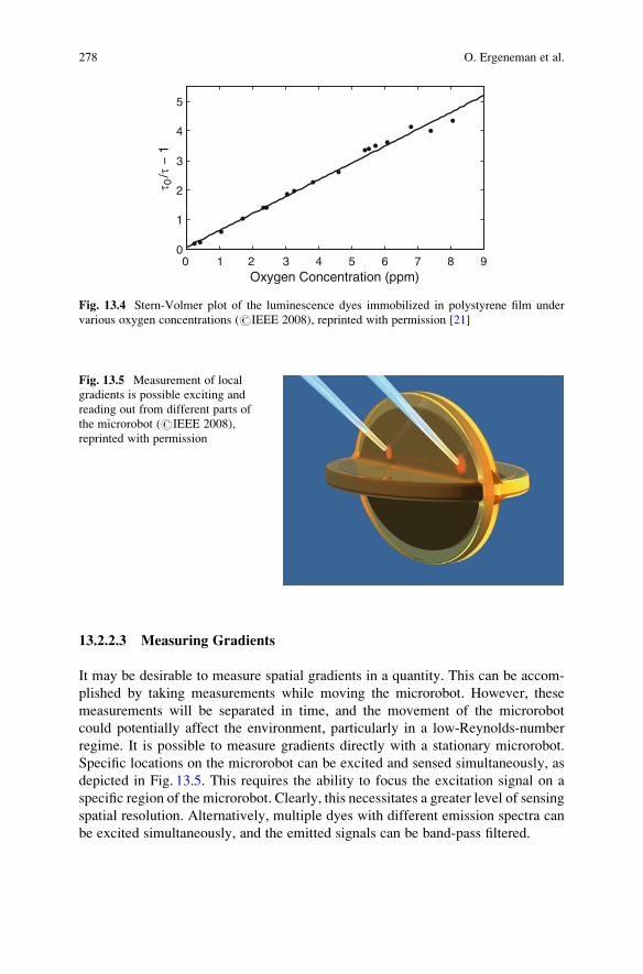
13.2.2.3 Measuring Gradients
It may be desirable to measure spatial gradients in a quantity. This can be accom-
plished by taking measurements while moving the microrobot. However, these
measurements will be separated in time, and the movement of the microrobot
could potentially affect the environment, particularly in a low-Reynolds-number
regime. It is possible to measure gradients directly with a stationary microrobot.
Specific locations on the microrobot can be excited and sensed simultaneously, as
depicted in Fig. 13.5. This requires the ability to focus the excitation signal on a
specific region of the microrobot. Clearly, this necessitates a greater level of sensing
spatial resolution. Alternatively, multiple dyes with different emission spectra can
be excited simultaneously, and the emitted signals can be band-pass filtered.
0 1 2 3 4 5 6 7 8 90
1
2
3
4
5
Oxygen Concentration (ppm)
τ 0/τ
− 1
Fig. 13.4 Stern-Volmer plot of the luminescence dyes immobilized in polystyrene film under
various oxygen concentrations (#IEEE 2008), reprinted with permission [21]
Fig. 13.5 Measurement of local
gradients is possible exciting and
reading out from different parts of
the microrobot (#IEEE 2008),
reprinted with permission
278 O. Ergeneman et al.
13.2.3 Coatings for Targeted Drug Delivery
Themain challenge of ophthalmic drug delivery is to keep desired drug concentrations
in the target area for the desired duration, while minimizing the drug levels in the
remainder of the body. To date, a variety of drug delivery approaches have been shown
to be effective therapeutically. Some salient findings from [48] are summarized below.
Ocular delivery can be achieved by topical administration, systemic administration,
periocular injections, and intraocular injections. Depending on the target area, drug
delivery can be achieved by penetrating through the cornea, conjunctiva, or sclera
following topical administration (i.e. eye drops), or across blood-aqueous barrier
along with blood-retinal barrier following systemic administration. Only a minute
fraction of applied dose reaches the intraocular target area after topical and systemic
administration. Drug delivery using gelatin wafers, collagen shields, and soft contact
lenses placed on the cornea or in the cul-de-sac have been tested, as well as methods
like iontophoresis. Drug delivery for posterior-segment disorders (e.g. diabetic reti-
nopathy, macular degeneration, retinal edema, retinal vein occlusions) has always
been a challenge as it requires access to the retina and the choroid. Periocular
injections and intraocular injections place the drug closer to the target tissue, over-
coming some of the ocular barriers.Many of the drugs used to treat vitreous and retinal
disorders have a narrow concentration range in which they are effective, and theymay
be toxic at higher concentrations. Slight changes in injection conditions (e.g. position,
shape) will produce different drug concentrations within the vitreous, and therefore
the efficacy of the treatment produced by the drug can be sensitive to injection
conditions. Intraocular injections have also been associated with serious side effects,
such as endophthalmitis, cataract, hemorrhage, and retinal detachment [26], and long-
duration drug delivery is not possible with these methods.
New drug-delivery methods provide many advantages compared to the tradi-
tional methods. However, it is not always possible to deliver drugs to the target
tissue with existing methods. Superior methods for targeted drug delivery are
needed, and robotic assistance in drug delivery will have major benefits. Devices
inserted into the aqueous or vitreous cavity bear great potential for drug delivery.
Recently, methods to deliver drugs using carriers such as liposomes, gels, and
nanoparticles have been evaluated. Methods to achieve desired concentrations
over long periods of time using drugs that become active inside the eye (prodrugs)
are also being investigated. Controlled-release devices and biodegradable implants
can increase the effectiveness of these devices.
At the microscale, diffusion becomes the dominant mechanism for mass trans-
port. Low-Reynolds-number flow is laminar, and the lack of turbulent mixing puts a
diffusion limit on drug delivery using micropumps. In [17] an alternative approach
to targeted drug delivery is proposed: wireless magnetic microrobots surface coated
with drug. The microrobot will be steered to the site of action and it will be kept at
this position as the drug is released from the microrobot by diffusion.
13 Wireless Intraocular Microrobots: Opportunities and Challenges 279
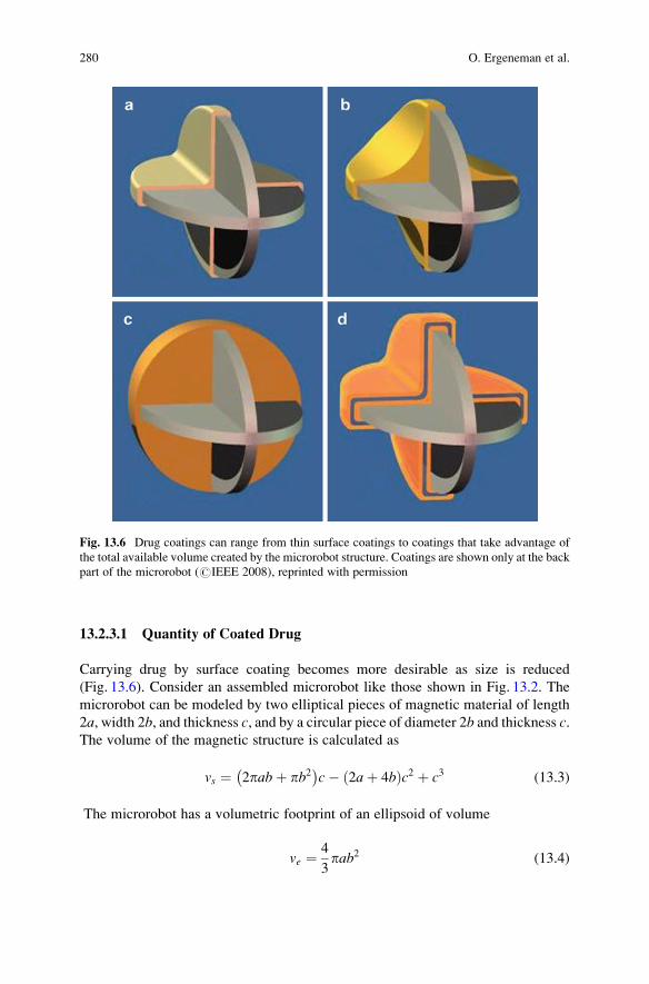
13.2.3.1 Quantity of Coated Drug
Carrying drug by surface coating becomes more desirable as size is reduced
(Fig. 13.6). Consider an assembled microrobot like those shown in Fig. 13.2. The
microrobot can be modeled by two elliptical pieces of magnetic material of length
2a, width 2b, and thickness c, and by a circular piece of diameter 2b and thickness c.The volume of the magnetic structure is calculated as
vs ¼ 2pabþ pb2� �
c� 2aþ 4bð Þc2 þ c3 (13.3)
The microrobot has a volumetric footprint of an ellipsoid of volume
ve ¼ 4
3pab2 (13.4)
Fig. 13.6 Drug coatings can range from thin surface coatings to coatings that take advantage of
the total available volume created by the microrobot structure. Coatings are shown only at the back
part of the microrobot (#IEEE 2008), reprinted with permission
280 O. Ergeneman et al.

If we consider a coating of drug that fills in the entire ellipsoidal volumetric
footprint of the microrobot (similar to Fig. 13.6c), the volume of drug carried is
simply the volume of the ellipsoid minus the volume of the magnetic structure
vf ¼ ve � vm (13.5)
If we consider a single thin surface coating of thickness t, (similar to Fig. 13.6a), the
volume of drug carried is given by
vt ¼ 4pabþ 2pb2� �
t� 8aþ 16b� 12cð Þt2 þ 8t3 (13.6)
Figure 13.7 shows the effect of scaling on the ability to carry drug by surface
coating. For even relatively large microrobots, the amount of drug carried on the
surface with a single thin coating is comparable to the total volume of the magnetic
structure. As the size of the microrobot is reduced, the volume of drug in a single
thin coating becomes comparable to the total ellipsoidal volume of the microrobot.
In practice, any fabricated reservoir could only amount to a fraction of the total
volume of the structure, and the drug would need to be in solution (that is, diluted)
in order to be pumped. The ability to surface coat highly concentrated drug
increases the benefits of surface coatings even beyond what is observed in
Fig. 13.7.
In order to bind more proteins or drugs onto a microrobot of the same surface
area, multilayer surface coatings or coatings embedded in different base matrices
should be developed (Fig. 13.6d). Among others, hydrogels, agarose, starch micro-
capsulations, polymer matrices, liposomes, and biodegradable needles are widely
used for making drug delivery matrices that can hold much more drug due to their
material properties [15, 50]. These materials can be used to encapsulate drug
102 103
106
107
108
109
a (µm)
Vol
ume
(µm
3 )
StructureEllipsoidFull CoatingThin Coating
t = 5µmt = 10µmt = 20µm
Fig. 13.7 Effect of scaling on volume with microrobots of the type shown in Fig. 13.2 (#IEEE
2008), reprinted with permission. Curves correspond to (3)–(6), respectively, with b¼ a / 2 and
c¼ a / 10
13 Wireless Intraocular Microrobots: Opportunities and Challenges 281

molecules as an outer coating, enabling multilayer coatings. These multilayer
coatings can be used to coat multiple drug types on one microrobot, or used to
fine tune delivery times or dosage. Alternatively, embedding drug molecules in a
porous matrix facilitates slower diffusion and more drug loading capacity. Con-
trolled release of drugs has been demonstrated using intelligent polymers that
respond to stimuli such magnetic fields, ultrasound, temperature, and pH. They
enable fine tuning of diffusive drug release.
13.2.3.2 Drug Delivery for Retinal Vein Occlusions
Retinal vein occlusion (RVO) is a common retinovascular disease caused by
obstruction of blood flow due to clot formation. RVO is among the most common
causes of vision loss around the world, with one study reporting a prevalence of
1. 6% in adults aged 49 years or older [60]. Various treatment methods for RVO
have been proposed and attempted, however to date there is no effective clinical
treatment for RVO. Among these methods, prolonged local intravenous thrombol-
ysis (i.e., clot dissolution) with tissue plasminogen activator (t-PA) injection is the
most promising treatment [53], based on excessive postoperative complications or
inconclusive clinical trials of other methods.
Retinal drug delivery by injections requires precise manipulation that is con-
strained by the limits of human performance and perception [34]. Retinal veins are
small delicate structures surrounded by fragile retinal tissue, and prolonged manual
cannulation of retinal veins risks causing permanent damage to the retina. Robotic
systems have been proposed to assist with retinal vein cannulation, utilizing robot-
assisted surgical instruments that pass through a hole in the sclera as in conven-
tional vitreoretinal surgery [47, 52].
In [17] an alternative approach to RVO treatment is proposed: a wireless
magnetic microrobot coated with clot-dissolving t-PA. The microrobot will be
steered to the thrombus site as it is tracked visually through the pupil, and will
be immobilized in close proximity of the retinal veins. Immobilization can be
achieved by puncturing and docking to a retinal vein. Diffusion of t-PA from the
surface coating of the microrobot into the clotted region will start clot dissolution.
There is strong evidence that t-PA in the preretinal area can diffuse into the retinal
vasculature and break clots [27]. Since t-PA is an enzyme, and the clot dissolution
reaction rate depends on enzyme reaction rate, long-term release of t-PA is thought
to be more effective than bolus injections [43]. The proposed delivery mechanism
provides drug release without the need for a micropump, and an efficient therapy
using small amounts of t-PA over prolonged periods. Moreover, a microrobot is
potentially less invasive than other methods, and has the potential to be left in the
eye for extended periods of time, even in an outpatient scenario. However, it is not
yet known what quantity of t-Pa is required to effectively dissolve a clot using the
proposed method.
282 O. Ergeneman et al.

13.2.3.3 Preliminary Drug Release Experiments
This section presents the results of preliminary drug release experiments using the
untethered microrobot and discusses the feasibility of microrobotic drug delivery.
A drug substitute is coated on microrobots in [17], the release kinetics is character-
ized, and the amount of drug that can be coated in a single layer on a microrobot is
quantified.
In order to analyze the release kinetics of a diffusion-based drug delivery
microrobot, in vitro experiments are conducted. As the drug molecule substitute,
bovine serum albumin (BSA) was chosen. BSA is a plasma protein that can be used
as a blocking agent or added to diluents in numerous biochemical applications.
BSA is used because of its stability, its inert nature in many biochemical reactions,
its representative molecular size, and its low cost.
Four elliptical microrobot pieces of length 900 mm, width 450 mm, and thickness
50 mm are used as the magnetic platform holding the coating. The pieces are made
from electroplated nickel and then coated with titanium for biocompatibility. The
pieces are first sterilized and then placed in different wells of a 96-well culture
plate. A sterilized BSA-solution of 3mg/mL is prepared and labeled with Alexa-
Fluor-546 (Molecular Probes) fluorescent marker. This solution is then mixed with
sterilized PBS in order to create solutions with different concentrations of labeled-
BSA molecules. Three of the microrobot pieces are dipped in BSA concentrations
of 3mg/mL, 2mg/mL, 1mg/mL, respectively, and one is dipped into a pure PBS
solution, which contained no BSA, as a control set. The pieces are left in the
solutions to allow the BSA to bind to the microrobot. The surface-coating process
is done for 12 h at room temperature in a humidity chamber.
Coated microrobot pieces are taken from coating wells and placed in new wells
filled with 200 mL PBS each. Following that, the florescence intensity is measured
in set time intervals for three days using an automated spectrum analyzer. In this
way, the kinetics of diffusion-based drug delivery with surface-coated microrobots
are obtained.
Figure 13.8 quantifies the amount of time required to release the drug through
diffusion, and it also gives qualitative information about the kinetics of release. It is
clear that the concentration of the coating solution does not affect the amount of
drug bound to the surface. This provides strong evidence that the amount of drug
will be limited by the surface area of the microrobot.
Next, the amount of BSA released from a single layer on a single piece is
quantified. The release wells of the culture plates are analyzed in the multiwell
plate reader for fluorescence and absorbance values. The BSA standard concentra-
tion curve is obtained by preparing a Bradford Assay with ten different known
concentrations of BSA in 1:2 dilutions, and analyzing this assay for fluorescence
and absorbance. The obtained standard curve is used to calibrate the multiwell plate
reader. The fluorescence intensity in the release wells is measured and, using the
calibration curve, the amount of BSA released is found to be 2. 5� 0. 1 mg.
13 Wireless Intraocular Microrobots: Opportunities and Challenges 283

13.3 Magnetic Control
One approach to the wireless control of microrobots is through externally applied
magnetic fields [3]. There is a significant body of work dealing with non-contact
magnetic manipulation [28]. Research has considered the 3-D positioning of per-
manent magnets [29, 36]. Magnetic fields have been used to orient small permanent
magnets placed at the distal tips of catheters [1, 62]. Researchers have considered
the position control of soft-magnetic beads as well, where a spherical shape
simplifies the control problem [6]. The precision control of non-spherical soft-
magnetic bodies has also been considered [2]. In addition to magnetic manipulation
of simple objects (e.g., beads, cylinders), it is possible to manipulate more compli-
cated shapes. In [66], a soft-magnetic assembled-MEMS microrobot is controlled
by applying decoupled magnetic torque and force. Assembled-MEMS microrobots
have the potential to provide increased functionality over simpler geometries.
Controlled magnetic fields can be generated by stationary current-controlled elec-
tromagnets [45, 67], by electromagnets that are position and current controlled
[29, 66s], or by position-controlled permanent magnets, such as with the Stereotaxis
NIOBE Magnetic Navigation System, or even by a commercial MRI system [44].
In all cases, the rapid decay of magnetic field strength with distance from its source
creates a major challenge for magnetic control.
Surgeons have been using magnets to remove metallic debris from eyes for over
100 years [9]. However, there has been no prior work of controlled magnetic
manipulation of an object that has been intentionally inserted in the eye. Intraocular
procedures are unique among in vivo procedures, as they provide a direct line of
sight through the pupil for visual feedback, making closed-loop control possible.
If we want to apply controlled torques and forces to an object with magnetization
M (A/m) using a controlled magnetic field B (T) the resulting equations for torque
0 20 40 60 80 100 1200
1
2
3
4
5x 10⁴
Time (min)
Flu
ores
cenc
e In
tens
ity (
A.U
.)3 mg/mL2 mg/mL1 mg/mL0 mg/mL
Fig. 13.8 Fluorescence intensity vs. time for the release experiment (#IEEE 2008), reprinted
with permission [17]
284 O. Ergeneman et al.

and force are as follows [35]. The magnetic torque, which tends to align the
magnetization of the object with the applied field:
T ¼ vM� B (13.7)
in units N �m where v is the volume of the body in m3. The force on the object is:
F ¼ v M � rð ÞB (13.8)
in units N, wherer is the gradient operator:
r ¼ @
@x
@
@y
@
@z
� �T(13.9)
Since there is no electric current flowing through the region occupied by the body,
Maxwell’s equations provide the constraint r�B¼ 0. This allows us to express
(8), after some manipulation, in a more intuitive and useful form:
F ¼ v
@
@xBT
@
@yBT
@
@zBT
26666664
37777775M (13.10)
The magnetic force in any given direction is the dot product of 1) the derivative of
the field in that direction and 2) the magnetization.
We can also express the applied magnetic field’s flux density as an applied
magnetic field H with units A/m. B is related to H simply as B¼ m0H with
m0¼ 4p �10� 7 T �m/A, since air and biological materials are effectively nonmag-
netic. Both (7) and (8) are based on the assumption that the magnetic body is small
compared to spatial changes in the applied magnetic field’s flux density, such that
the applied flux density is fairly uniform across the body, and B is the value at the
center of mass of the body. It has been verified experimentally that this assumption
gives an accurate prediction of magnetic force and torque [2, 49].
If the body of interest is a permanent magnet, the average magnetization M is
effectively independent of the applied magnetic field. The magnetization of a
permanent magnet is governed by the remanent magnetization of the material and
geometry of the body. This makes the calculation of torque and force acting on a
permanent magnetic body straightforward as long as the magnetization and orien-
tation of the body is known. The torque can be increased by increasing the angle
between B and M, up to 90 ∘ , or by increasing the strength of B. The force can be
increased by increasing the gradients in the applied magnetic field.
13 Wireless Intraocular Microrobots: Opportunities and Challenges 285
If the body of interest is made of a soft-magnetic material, the magnetization is a
nonlinear function of the applied field, with a magnitude limited by the saturation
magnetization for the magnetic material, and can rotate with respect to the body.
The governing equations for control are significantly more complex [2]. We
sometimes refer to the magnetic moment or magnetic dipole moment, which
represent the total strength of a magnet (hard or soft). The magnetic moment is
simply the product of the volume v and the average magnetization M.
The magnetization of a body depends on its shape, so bodies made of the same
material but having different shapes will have different magnetization character-
istics. The magnetization characteristics also differ along different directions within
the body. This is known as shape anisotropy. Demagnetizing fields that tend to
weaken magnetization create the shape anisotropy. Demagnetizing fields are largest
along short directions of the body. A long direction in a body is referred to as an
easy axis, since it is a relatively easy direction to magnetize the body. In general, the
longest dimension of a soft-magnetic body will tend to align with the direction of
the applied field. Other types of anisotropy exist, such as crystalline anisotropy, but
these are typically negligible compared to shape effects, even at the scale of
microrobots.
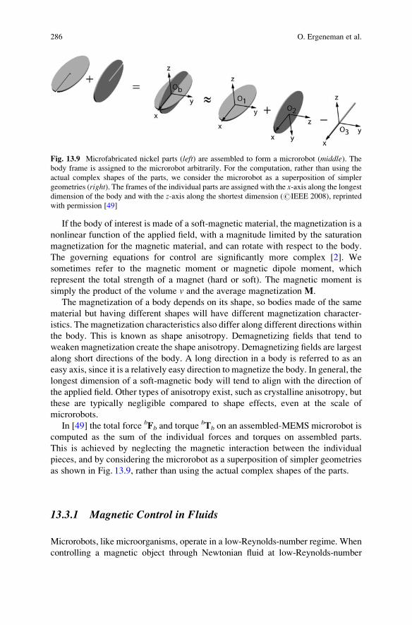
In [49] the total force bFb and torquebTb on an assembled-MEMS microrobot is
computed as the sum of the individual forces and torques on assembled parts.
This is achieved by neglecting the magnetic interaction between the individual
pieces, and by considering the microrobot as a superposition of simpler geometries
as shown in Fig. 13.9, rather than using the actual complex shapes of the parts.
13.3.1 Magnetic Control in Fluids
Microrobots, like microorganisms, operate in a low-Reynolds-number regime. When
controlling a magnetic object through Newtonian fluid at low-Reynolds-number
Fig. 13.9 Microfabricated nickel parts (left) are assembled to form a microrobot (middle). Thebody frame is assigned to the microrobot arbitrarily. For the computation, rather than using the
actual complex shapes of the parts, we consider the microrobot as a superposition of simpler
geometries (right). The frames of the individual parts are assigned with the x-axis along the longestdimension of the body and with the z-axis along the shortest dimension (#IEEE 2008), reprinted
with permission [49]
286 O. Ergeneman et al.

regime, the object nearly instantaneously reaches its terminal velocity V where the
viscous drag force, which is linearly related to velocity through a drag coefficient cu,
exactly balances the applied magnetic force F:
F ¼ cuV (13.11)
Similarly, the object nearly instantaneously reaches its terminal rotational velocity
O where the viscous drag torque, which is linearly related to rotational velocity
through a drag coefficient co, exactly balances the applied magnetic torque T.
T ¼ coO (13.12)
If we consider a spherical body of diameter d and a fluid with viscosity Z, thetranslational and rotational drag coefficients are described in Stokes flow (see [64]) as:
cu ¼ 3p�d (13.13)
co ¼ p�d3 (13.14)
It is clear that velocity is inversely proportional to fluid viscosity with all other
parameters held constant.
In [39] hydrodynamic properties of assembled-MEMS microrobots are deter-
mined experimentally by placing a microrobot in a known-fluid-filled vial and
tracking it by digital cameras as it sinks under its own weight and under different
applied magnetic forces. Modeling an assembled-MEMSmicrorobot as a sphere for
the purposes of calculating fluid drag is found to be quite accurate. This also agrees
with the typical assumption that fluid drag is insensitive to geometry at low
Reynolds number. The coefficient of viscous drag of the microrobot in a Newtonian
fluid obtained in [39] is found to be cu¼ (1. 41 �10� 2N �s/m) � d.The calculations in this section assume a Newtonian fluid, which will be a valid
assumption after a vitrectomy has been performed. In the presence of intact vitreous
humor, a more complicated fluid model must be considered.
13.3.2 Developing Sufficient Force for Levitation and Puncture
There is interest in determining the amount of force that can be developed wire-
lessly for the purpose of puncturing retinal veins. A drug delivery method where the
microrobot docks to a blood vessel to allow the drug to release over extended
periods of time is proposed, as shown in Fig. 13.10. This will require a microneedle
to puncture the blood vessel. The magnetic forces on microrobots in applied
magnetic fields are well understood. However, the magnitude of forces needed to
puncture retinal veins is not available in the literature.
13 Wireless Intraocular Microrobots: Opportunities and Challenges 287

13.3.2.1 Retinal Puncture Forces
In [34], retinal puncture forces together with the scleral interaction forces are
measured. However, needle and blood-vessel size, which affect puncture forces,
are not specified. In [30], a retinal pick equipped with strain gauges is used to
manipulate the retina of porcine cadaver eyes, and the range of forces acquired
during a typical procedure is reported. However, the force of an individual retinal
vein puncture is not provided. Conducting in vivo experiments on animal eyes is
difficult with a high risk of tissue damage, and postmortem experiments may
provide inaccurate results due to rapid changes in tissue properties of vessels
after death. In [17], forces required for retinal vein punctures are measured and
analyzed. Experimental data is collected from the vasculature of chorioallantoic
membranes (CAM) of developing chicken embryos. The CAM of the developing
chicken embryo has been used by ophthalmologists as a model system for studying
photodynamic therapy and ocular angiogenesis. Recently, it was reported that the
CAM of a twelve-day-old chicken embryo is a valid test bed for studies on human
retinal vessel puncture [41]. The CAM’s anatomical features and physiologic and
histologic responses to manipulation and injury make it an effective living model of
the retina and its vasculature. The vasculature of a twelve-day-old CAM and a
human retina have roughly the same diameter and wall thickness (i.e., vessels with
100–300 mm outer diameter). The measurements are done using a capacitive force
sensor with an attached microneedle, mounted on a 3-DOF Cartesian micromanip-
ulator. Microneedles were pulled out of 1mm OD boron-silicate glass pipettes in a
repeatable way using a pipette puller and the outer diameters were inspected with a
microscope.
There is variance in the force data due to effects that are not accounted for, such
as anatomical variance between individual vessels and embryos, the state of the
embryo (e.g., blood pressure, temperature), non-Hookean behavior of the vessel
walls, errors in measured microneedle diameter, and error in the angle of incidence
Fig. 13.10 Concept photo of a microrobot docked to a blood vessel for drug delivery (#IEEE
2008), reprinted with permission [17]. The assembled-MEMS microrobot shown is based on [66]
288 O. Ergeneman et al.

of the microneedle with respect to the blood vessel. Despite the variance, the data
exhibit clear trends, as shown in Fig. 13.11. It is observed that there is an approxi-
mately quadratic trend in blood-vessel diameter and an approximately linear trend
in microneedle diameter.
The experiments are performed with blunt-tip needles, so the forces shown in
Fig. 13.11 should be taken as upper bounds for required puncture forces. It is known
that beveling the needle’s tip will significantly reduce the puncture forces [5, 16].
In [30], it is shown that 88% of all tool/tissue interaction forces during vitreor-
etinal surgery are below 12.5mN, which corresponds well with the results shown in
Fig. 13.11. In [34], higher puncture forces with larger variance than the results in
Fig. 13.11 are reported. However, the reported forces include scleral interaction
forces, and the force sensor is mounted on a handheld device.
13.3.2.2 Developing Sufficient Force
Let us consider a microrobot assembled from two thin elliptical pieces, as shown in
the inset of Fig. 13.12. The volume of this microrobot is given by v¼ 2pabt� 2at2.The force on such assembled microrobots made of Ni and CoNi are measured using
the magnetic measurement system described in [39], and the results are shown in
Fig. 13.12. The system uses a 40mm� 40mm� 20mm NdFeB magnet with the
north and south poles on the largest faces, and a field value of 0.41 T measured in
the center of the north pole face. In addition to the measured data, a microrobot
made of permanent-magnetic (hard-magnetic) material with a remanence magneti-
zation of 4�105A/m, which is a value that can currently be achieved using
microfabrication techniques, is simulated.
100 150 200 250 300 350 40010−1
100
101
Blood Vessel Outer Diameter (µm)
Pun
ctur
e F
orce
(m
N)
3.3 µm6.7 µm43 µm58 µm76 µm90 µm
Fig. 13.11 Experimental data of puncture force with blunt tip microneedles vs. vessel diameter
for different microneedles ODs (#IEEE 2008), reprinted with permission [17]
13 Wireless Intraocular Microrobots: Opportunities and Challenges 289
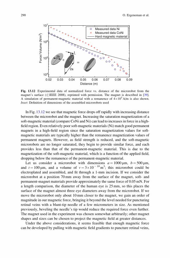
In Fig. 13.12 we see that magnetic force drops off rapidly with increasing distance
between the microrobot and the magnet. Increasing the saturation magnetization of a
soft-magnetic material (compare CoNi and Ni) can lead to increases in force in a high-
field region. Even relatively poor soft-magnetic materials (Ni) match good permanent
magnets in a high-field region since the saturation magnetization values for soft-
magnetic materials are typically higher than the remanence magnetization values of
permanent magnets. However, as field strength is reduced, and the soft-magnetic
microrobots are no longer saturated, they begin to provide similar force, and each
provides less than that of the permanent-magnetic material. This is due to the
magnetization of the soft-magnetic material, which is a function of the applied field,
dropping below the remanence of the permanent-magnetic material.
Let us consider a microrobot with dimensions a¼ 1000 mm, b¼ 500 mm,
and t¼ 100 mm, and a volume of v¼ 3�10� 10m3; this microrobot could be
electroplated and assembled, and fit through a 1-mm incision. If we consider the
microrobot at a position 70mm away from the surface of the magnet, soft- and
permanent-magnet materials provide approximately the same force of 0.05mN. For
a length comparison, the diameter of the human eye is 25mm, so this places the
surface of the magnet almost three eye diameters away from the microrobot. If we
move the microrobot only about 10mm closer to the magnet, we gain an order of
magnitude in our magnetic force, bringing it beyond the level needed for puncturing
retinal veins with a blunt-tip needle of a few micrometers in size. As mentioned
previously, beveling the needle’s tip would reduce the required force even further.
The magnet used in the experiment was chosen somewhat arbitrarily; other magnet
shapes and sizes can be chosen to project the magnetic field at greater distances.
Under the above considerations, it seems feasible that enough magnetic force
can be developed by pulling with magnetic field gradients to puncture retinal veins,
2b
2a
+ =
t
0.02 0.03 0.04 0.05 0.06 0.07 0.08 0.09
104
105
106
107
Distance (m)
For
ce/V
olum
e (N
/m3 )
Measured data NiMeasured data CoNiHard magnetic material
Fig. 13.12 Experimental data of normalized force vs. distance of the microrobot from the
magnet’s surface (#IEEE 2008), reprinted with permission. The magnet is described in [39].
A simulation of permanent-magnetic material with a remanence of 4�105A/m is also shown.
Inset: Definition of dimensions of the assembled microrobots used
290 O. Ergeneman et al.
provided that the microneedle is made small enough and sharp enough. These
demands are attainable with current microfabrication technology. Puncture also
requires an intelligent design of the magnetic-field generation system, which will
use the superimposed fields of multiple permanent magnets or electromagnets,
increasing the ability to generate strong fields at a distance. The choice of soft- or
permanent-magnetic material for the microrobot will ultimately depend on the
design of the magnetic-field generation system. This issue of force generation is
discussed further in the next section.
It has been shown that microrobots that swim using helical propellers that mimic
bacterial flagella theoretically have the potential to develop higher forces than
obtained with gradient-based force generation at small scales [4]. It has also
recently been shown that magnetic helical microrobots can be fabricated and
wirelessly controlled [67]. This provides another option for retinal drug delivery.
13.3.3 OctoMag
There are two viable sources for the generation of controlled magnetic fields: perma-
nent magnets and electromagnets. Permanent magnets exhibit a very advantageous
volume to field-strength ratio. However, if we are interested in medical applications,
electromagnets offer simpler real-time control, and present an inherently safer choice.
A system using electromagnets can be implemented such that no moving parts are
required to control magnetic field strength. This is important for both patient and
medical-personnel safety. In addition, electromagnets are safer in the event of system
failure: permanent magnets retain their attractive/repulsive strength in case of sudden
power loss, whereas an electromagnetic system becomes inert, and in addition for the
case of an intraocular microrobotic agent, the microrobot would slowly drift down
under its ownweight rather than experiencing uncontrolled forceswith the potential of
inflicting irreparable damage inside the eye. Using an array of stationary magnetic
field sources also simplifies the task of designing a system that will respect the
geometry of the human head, neck, and shoulders.
Bearing these considerations in mind, a robotic system called OctoMag for 5-DOF
wireless magnetic control of a fully untethered microrobot (3-DOF position, 2-DOF
pointing orientation)was developed at ETHZurich [38]. It is difficult to control torque
about the axis ofM using the simple model in (7), which is why 5-DOF control was
achieved as opposed to 6-DOF control. A concept image of how the system would be
used for the control of intraocular microrobots can be seen in Fig. 13.13.
13.3.3.1 Control with Stationary Electromagnets
Soft-magnetic-core electromagnets can create a magnetic field that is approxi-
mately 20 times stronger than the magnetic field created by air-core electromagnets,
for the geometry shown in Fig. 13.13. As opposed to air-core electromagnets, their
13 Wireless Intraocular Microrobots: Opportunities and Challenges 291

individual magnetic fields are coupled, which complicates modeling and control.
However, cores made of high-performance soft-magnetic materials impose only a
very minor constraint on modeling and control [38].
Within a given static arrangement of electromagnets, each electromagnet creates
a magnetic field throughout the workspace that can be precomputed. At any given
point in the workspace P, the magnetic field due to a given electromagnet can be
expressed by the vector Be(P), whose magnitude varies linearly with the current
through the electromagnet, and as such can be described as a unit-current vector in
units T/m multiplied by a scalar current value in units A:
BeðPÞ ¼ ~BeðPÞie (13.15)
The subscript e represents the contribution due to the eth electromagnet. However,
although the field Be(P) is the field due to the current flowing through only
electromagnet e, it is due to the soft-magnetic cores of every electromagnet. With
air-core electromagnets, the individual field contributions are decoupled, and the
fields can be individually precomputed and then linearly superimposed. This in not
the case with soft-magnetic-core electromagnets. However, if an ideal soft-mag-
netic material with negligible hysteresis is assumed, and the system is operated with
the cores in their linear magnetization region, the assumption is still valid that the
field contributions of the individual currents (each of which affect the magnetiza-
tion of every core) superimpose linearly. Thus, if the field contribution of a given
electromagnet is precomputed in situ, it can be assumed that the magnetic field at a
point in the workspace is the sum of the contributions of the individual currents.
This assumption is clearly also valid for air-core electromagnets and the linear
summation of fields can be expressed as:
Fig. 13.13 Concept image of the OctoMag electromagnetic system: An eyeball is at the center of
the system’s workspace (#IEEE 2010), reprinted with permission. The electromagnet arrange-
ment accommodates the geometry of the head, neck, and shoulders. The OctoMag is designed for a
camera to fit down the central axis to image the microrobot in the eye
292 O. Ergeneman et al.

BðPÞ ¼ ~B1ðPÞ � � � ~BnðPÞ� � i1
..
.
in
2664
3775 ¼ BðPÞI (13.16)
The 3�n BðPÞ matrix is defined at each point P in the workspace, which can either
be analytically calculated online, or a grid of precomputed or measured points can
be interpolated online. It is also possible to express the derivative of the field in a
given direction in a specific frame, for example the x direction, as the contributionsfrom each of the currents:
@BðPÞ@x ¼ @~B1ðPÞ@x
� � � @~BnðPÞ@x
� � i1
..
.
in
2664
3775 ¼ BxðPÞI (13.17)
If we are interested in controlling a microrobot moving through fluid, where the
microrobot can align with the applied field unimpeded, rather than controlling
torque and force acting on the microrobot, we can simply control the magnetic
field to the desired orientation, to which the microrobot will naturally align, and
then explicitly control the force on the microrobot:
B
F
" #¼ v
BðPÞMTBxðPÞMTByðPÞMTBzðPÞ
266664
377775
i1
..
.
in
2664
3775 ¼ AðM;PÞI (13.18)
That is, for each microrobot pose, the n electromagnet currents are mapped to a field
and force through a 6�n actuation matrixAðM;PÞ. For a desired field/force vector,the choice of currents that gets us closest to the desired field/force value can be
found using the pseudoinverse:
I ¼ AðM;PÞy Bdes
Fdes
" #(13.19)
Full 5-DOF control requires a rank-6 actuation matrix A. If there are multiple
solutions to achieve the desired field/force, the pseudoinverse finds the solution that
minimizes the 2-norm of the current vector, which is desirable for the minimization
of both power consumption and heat generation. Note that the use of (19) requires
knowledge of the microrobot’s pose and magnetization. If the direction of B does
not change too rapidly, it is reasonable to assume that M is always aligned with B,
13 Wireless Intraocular Microrobots: Opportunities and Challenges 293

which means that one need not explicitly measure the microrobot’s full pose, but
rather, must only estimate the magnitude of M and measure the microrobot’s
position P. In addition, if we the magnetic field does not vary greatly across the
workspace, it may be reasonable to assume that the microrobot is always located at
P¼ 0 for purposes of control, eliminating the need for any localization of the
microrobot.
There are a number of potential methods to generate the unit-current field maps
that are required for the proposed control system. One can either explicitly measure
the magnetic field of the final system at a grid of points or compute the field values
at the grid of points using FEM models. In either case trilinear interpolation is used
during real-time control. To generate the unit-current gradient maps using either
method, one can either explicitly measure/model the gradient at the grid of points,
or numerically differentiate the field data. Alternatively, one can fit an analytical
model – for example the point-dipole model [24] – to field data obtained from an
FEM model of the final system for each of the unit-current contributions.
An analytical field model also has an analytical derivative. These analytical models
can then be used to build the unit-current field and gradient maps during run time.
13.3.3.2 System Implementation
Equipped with a general control system using n stationary electromagnets, it is now
possible to use this controller in the design of a suitable electromagnet configura-
tion. The singular values of the actuation matrix in (18) provide information on the
condition of the workspace and can be used as performance metric in a design
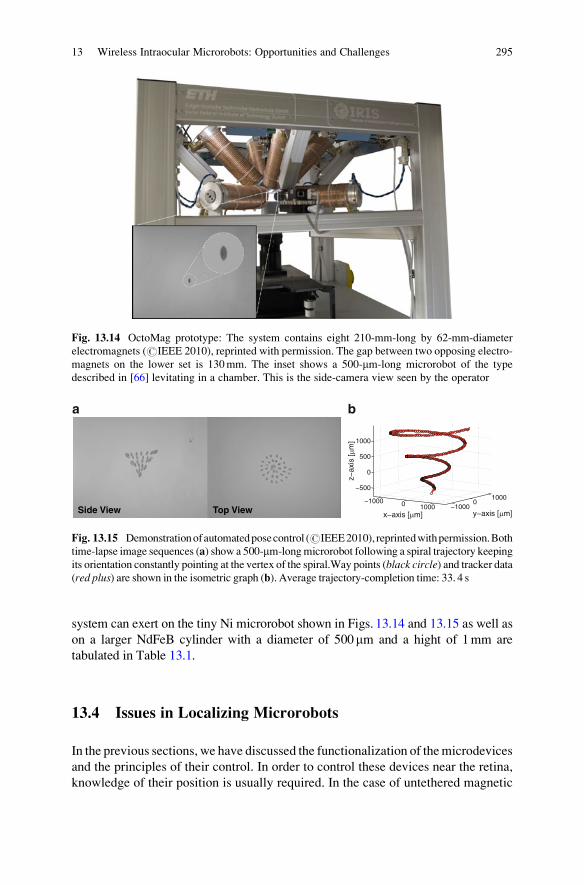
optimization [38]. Figure 13.14 shows a physical embodiment of the concept image
presented earlier. This prototype setup was designed with a workspace that is large
enough that, after experimenting in artificial and ex vivo eyes, could be used for
animal trials with live cats and rabbits.
Each electromagnet is completely filled with a core made of VACOFLUX 50 –
a CoFe alloy from VACUUMSCHMELZE – with a diameter of 42mm. This
material has a saturation magnetization on the order of 2. 3 T, a coercivity of
0. 11mT, and a maximum permeability of 4500H/m. To prevent temperatures
inside the coils to elevate beyond 45∘C, every electromagnet is wrapped with a
cooling system. The current for the electromagnetic coils is sourced through
custom-designed switched amplifiers to reduce the power consumption. Two sta-
tionary camera assemblies provide visual feedback from the top and side and allow
to extract the 3-D position of a microrobot in the system. For the envisioned
intraocular application the visual feedback will have to be produced using a single
camera which is detailed in Sect. 4.
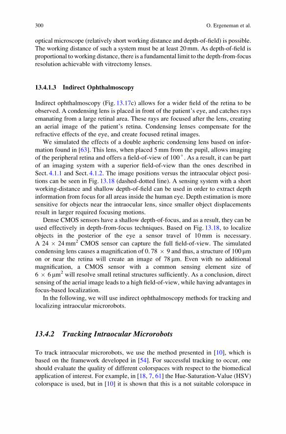
An example of the manipulation capabilities of the system can be seen in
Fig. 13.15. Automated pose control refers to closed-loop position control with open-
loop orientation control. The system exhibits similar performance in a wide array of
different trajectories as well as for a variety of robot orientations. The forces this
294 O. Ergeneman et al.
system can exert on the tiny Ni microrobot shown in Figs. 13.14 and 13.15 as well as
on a larger NdFeB cylinder with a diameter of 500mm and a hight of 1mm are
tabulated in Table 13.1.
13.4 Issues in Localizing Microrobots
In the previous sections, we have discussed the functionalization of themicrodevices
and the principles of their control. In order to control these devices near the retina,
knowledge of their position is usually required. In the case of untethered magnetic
Fig. 13.14 OctoMag prototype: The system contains eight 210-mm-long by 62-mm-diameter
electromagnets (#IEEE 2010), reprinted with permission. The gap between two opposing electro-
magnets on the lower set is 130mm. The inset shows a 500-mm-long microrobot of the type
described in [66] levitating in a chamber. This is the side-camera view seen by the operator
Side View Top View−1000 0 1000 −1000
01000
−500
0
500
1000
y−axis [μm]x−axis [μm]
z−ax
is [μ
m]
a b
Fig. 13.15 Demonstrationofautomatedposecontrol (#IEEE2010), reprintedwithpermission.Both
time-lapse image sequences (a) show a 500-mm-longmicrorobot following a spiral trajectory keeping
its orientation constantly pointing at the vertex of the spiral.Way points (black circle) and tracker data(red plus) are shown in the isometric graph (b). Average trajectory-completion time: 33. 4 s
13 Wireless Intraocular Microrobots: Opportunities and Challenges 295

devices, knowledge of the position of the device within the magnetic field is
necessary for precise control [2, 49]. Since, the interior of the human eye is
externally observable, vision can be used to perform 3D localization. In addition,
with clear images of the retina and the microrobot, visual feedback can be used to
close a visual-servoing loop to correct for any errors in the localization procedure.
Ophthalmic observation has been practices for centuries, with its most critical
task being to be able to visualize the human retina with high-definition. Nowadays,
clinicians have the ability to acquire magnified images of the human retina using an
ever-increasing variety of optical tools that are designed specifically for the unique
optical system that is the human eye (Fig. 13.16).
However, keeping intraocular objects that are freely moving in the vitreous
humor of the eye (and not just on the retina) constantly in focus is challenging,
and the captured images are often blurry and noisy. The unstructured illumination
that reaches the interior of the eye, either through endoillumination, transpupilary
or transscleral means, can deteriorate the images with uneven brightness and
backreflections. Moreover, the microtools that operate in the human eye are gener-
ally specular, and have no distinctive color features. For precise localization, robust
visual tracking that detect the microrobot in the images is needed. The extracted
segmentation information will be used for 3D localization.
Ciliary body
Pupil
Cornea Iris
Lens
Sclera
Retina
Choroid
Fovea
Optic Nerve
National Cancer Institute
Aqueous humor
a b
Fig. 13.16 (a) Anatomy of the human eye. (b) The biomedical microrobot of [66] in the model
eye [31]. The left image shows the intraocular environment without the eye’s optical elements, and
the right image shows the effect of the model eye optics. Images are taken with an unmodified
digital camera (#IEEE 2008), reprinted with permission
Table 13.1 Maximum force in OctoMag setup on a small Ni microrobot and a full NdFeB
cylinder for various agent orientations (#IEEE 2010), reprinted with permission
Ni Microrobot NdFeB Cylinder
Field
Orientation
Fup
ðmNÞFdown
ðmNÞFlat;x
ðmNÞFlat;y
ðmNÞFlat;xy
ðmNÞFup
ðmNÞFdown
ðmNÞFlat;x
ðmNÞFlat;y
ðmNÞFlat;xy
ðmNÞz 2. 1 1. 3 1. 1 1. 3 1. 4 281 221 141 172 200
� z 3. 3 2. 1 1. 7 2. 0 2. 2 281 221 141 172 200
x 2. 2 2. 2 3. 6 3. 1 3. 9 189 222 213 341 276
xy 2. 7 2. 7 4. 1 3. 0 2. 5 274 263 263 286 259
296 O. Ergeneman et al.

The literature lacks algorithms for the localization of untethered intraocular
devices. In addition, because the microrobots will be controlled by a magnetic-
field-generation system surrounding the patient’s head, we are interested in com-
pact solutions that utilize a single stationary camera. In the following sections, we
will introduce the first intraocular localization algorithm, using a custom-built
stationary camera. Our approach is based on depth-from-focus [20]. Focus-based
methods do not require a model of the object of interest, but only knowledge of the
optical system. Applied in the eye, they could also localize unknown objects such as
floaters. As a result, our analysis need not be considered only in the scope of
microrobot localization, but is applicable on any type of unknown foreign bodies.
In the following, we will firstly evaluate different ophthalmoscopy methods with
respect to their advantages in imaging and localizing. Then, based on our results, we
will introduce a level-set tracking algorithm that successfully segments intraocular
microdevices in images. Finally, we will present a method for wide-angle intraocu-
lar localization.
13.4.1 Comparison of Ophthalmoscopy Methods
Our results are based on Navarro’s schematic eye [22] (i.e. an optical model based on
biometric data that explains the optical properties of the human eye). Navarro’s
schematic eye performs well for angles up to 70∘ measured from the center of the
pupil and around the optical axis. For greater angles, the biometric data of each patient
should be considered individually. Simulations are carried out with the OSLO optical
lens design software. Throughout this section, the object’s depth z is measured along
the optical axis. We begin by investigating the feasibility of imaging and localizing
intraocular devices using existing ophthalmoscopy methods.
13.4.1.1 Direct Ophthalmoscopy
In a relaxed state, the retina is projected through the eye optics as a virtual image at
infinity. An imaging system can capture the parallel beams to create an image of the
retina. In direct ophthalmoscopy the rays are brought in focus on the observer’s
retina [57]. By manipulating the formulas of [56] the field-of-view for direct
ophthalmoscopy is found as 10 ∘ (Fig. 13.17a).
Every object inside the eye creates a virtual image. These images approach
infinity rapidly as the object approaches the retina. Figure 13.18 (solid line) displays
the distance where the virtual image is formed versus different positions of an
intraocular object. In order to capture the virtual images that are created from
objects close to the retina, an imaging system with near to infinite working distance
is required. Such an imaging system will also have a large depth-of-field, and depth
information from focus would be insensitive to object position (Table 13.2).
13 Wireless Intraocular Microrobots: Opportunities and Challenges 297

13.4.1.2 Vitrectomy Lenses
To visualize devices operating in the vitreous humor of phakic (i.e. intact intraocu-
lar lens) eyes, only plano-concave lenses (Fig. 13.17b) need to be considered [57].
Vitrectomy lenses cause the virtual images of intraocular objects to form inside the
eye, allowing the imaging systems to have a reduced working distance. Based on
data given from HUCO Vision SA for the vitrectomy lens S5. 7010 [23], we
simulated the effects of a plano-concave vitrectomy lens on Navarro’s eye
(Fig. 13.17b). This lens allows for a field-of-view of 40 ∘ , significantly larger than
the one obtainable with the method described in Sect. 4.1.1.
As shown in Fig. 13.18 (dashed line), the virtual images are formed inside the eye
and span a lesser distance. Thus, contrary to direct observation, imaging with an
1 2 3 4 5c6c 7100o1 2 3 4 5a10o 1 3 4 5b6b40o 2
a b c
Fig. 13.17 (a) Direct ophthalmoscopy with Navarro’s schematic eye [22]. (b) Ophthalmoscopy
with Navarro’s schematic eye with a vitrectomy lens [23]. (c) Indirect ophthalmoscopy with
Navarro’s schematic eye with a condensing lens [63] (#IEEE 2008), reprinted with permission
−24 −22 −20 −18 −16 −14 −12 −10 −8−25
−20
−15
−10
−5
0
5
10
15
20
25
30
35
40
45
50
55
Object distance from cornea (mm)
Imag
e po
sitio
n (m
m)
Direct Ophthalmoscopy with Navarro’s Eye
Vitrectomy-Lens Case
Indirect Ophthalmoscopy with Navarro’s Eye and a Condensing Lens
Fig. 13.18 Image position versus intraocular object position for the direct ophthalmoscopy case,
the vitrectomy-lens case, and the indirect ophthalmoscopy case. Image distances are measured
from the final surface of each optical system (5a, 6b, 7 respectively) (#IEEE 2009), reprinted with
permission
298 O. Ergeneman et al.

Table
13.2
Opticalparam
etersforthesystem
sofFig.13.17(#
IEEE2008),reprintedwithpermission
Surface
12
34
5a
5b
5c
6b
6c
7
Radius(m
m)
12.00
6.00
�10.20
�6.50
�7.72
�7.72
�7.72
111.65
�9.48
Conic
constant
0.00
�1.00
�3.13
0.00
�0.26
�0.26
�0.26
0.00
�9.24
�1.07
Thickness(m
m)
16.32
4.00
3.05
0.55
12.00
2.00
113.00
1Refractionindex
1.336
1.420
1.337
1.376
1.000
1.425
1.000
1.000
1.523
1.000
13 Wireless Intraocular Microrobots: Opportunities and Challenges 299
optical microscope (relatively short working distance and depth-of-field) is possible.
The working distance of such a system must be at least 20mm. As depth-of-field is
proportional toworking distance, there is a fundamental limit to the depth-from-focus
resolution achievable with vitrectomy lenses.
13.4.1.3 Indirect Ophthalmoscopy
Indirect ophthalmoscopy (Fig. 13.17c) allows for a wider field of the retina to be
observed. A condensing lens is placed in front of the patient’s eye, and catches rays
emanating from a large retinal area. These rays are focused after the lens, creating
an aerial image of the patient’s retina. Condensing lenses compensate for the
refractive effects of the eye, and create focused retinal images.
We simulated the effects of a double aspheric condensing lens based on infor-
mation found in [63]. This lens, when placed 5mm from the pupil, allows imaging
of the peripheral retina and offers a field-of-view of 100 ∘ . As a result, it can be part
of an imaging system with a superior field-of-view than the ones described in
Sect. 4.1.1 and Sect. 4.1.2. The image positions versus the intraocular object posi-
tions can be seen in Fig. 13.18 (dashed-dotted line). A sensing system with a short
working-distance and shallow depth-of-field can be used in order to extract depth
information from focus for all areas inside the human eye. Depth estimation is more
sensitive for objects near the intraocular lens, since smaller object displacements
result in larger required focusing motions.
Dense CMOS sensors have a shallow depth-of-focus, and as a result, they can be
used effectively in depth-from-focus techniques. Based on Fig. 13.18, to localize
objects in the posterior of the eye a sensor travel of 10mm is necessary.
A 24 � 24mm2 CMOS sensor can capture the full field-of-view. The simulated
condensing lens causes a magnification of 0. 78 � 9 and thus, a structure of 100 mmon or near the retina will create an image of 78 mm. Even with no additional
magnification, a CMOS sensor with a common sensing element size of
6 � 6 mm2 will resolve small retinal structures sufficiently. As a conclusion, direct
sensing of the aerial image leads to a high field-of-view, while having advantages in
focus-based localization.
In the following, we will use indirect ophthalmoscopy methods for tracking and
localizing intraocular microrobots.
13.4.2 Tracking Intraocular Microrobots
To track intraocular microrobots, we use the method presented in [10], which is
based on the framework developed in [54]. For successful tracking to occur, one
should evaluate the quality of different colorspaces with respect to the biomedical
application of interest. For example, in [18, 7, 61] the Hue-Saturation-Value (HSV)
colorspace is used, but in [10] it is shown that this is a not suitable colorspace in
300 O. Ergeneman et al.

Fig. 13.19 Tracking using (a), (b) the R-G channels of the RGB colorspace without and with
thresholds, respectively, (c), (d) the Y-V channels of the YUV colorspace without and
with thresholds, respectively, (e), (f) the H-S channels of the HSV colorspace without and with
thresholds, respectively (# IEEE 2009), reprinted with permission
13 Wireless Intraocular Microrobots: Opportunities and Challenges 301

which to track intraocular microdevices. Tracking in the best colorspace ensures
reduced vein segmentation; compare Fig. 13.19a with Fig. 13.19c and Fig. 13.19e).
After choosing the appropriate colorspace, thresholds that ensure the maximum
object-from-background separation are calculated. These thresholds help vanish the
erroneous vein segmentation, and lead to successful detection of the microrobot in
the images (Fig. 13.19b, d). If the selected colorspace/channel combination is not of
appropriate quality, the thresholds will cause the tracking to fail (Fig. 13.19e).
To further increase the segmentation accuracy, in [10], the statistical shape prior
evolution framework of [42] is adapted and used. Using shape information together
with the color information ensures diminished vein segmentation, as the misclassi-
fications are discarded by the shape information. Figure 13.20 compares tracking in
R-G, and tracking in R-G using shape information; when shape information is
incorporated the results are improved.
13.4.3 Wide-Angle Localization
With the tracking method of [10] we can robustly estimate the position of an
intraocular microrobot in images, successfully handling cases of occlusion and of
defocus. However, in order to perform accurate magnetic control, we need to know
its 3D position in the intraocular environment. Here, we present a method for wide-
angle intraocular localization using focus information. This method was first
introduced by Bergeles et al. [12].
13.4.3.1 Theory of Intraocular Localization
As previously stated, the condensing lens projects the spherical surface of the retina
onto a flat aerial image. Moving the sensor with respect to the condensing lens
focuses the image at different surfaces inside the eye, which we call isofocus
Fig. 13.20 Tracking using color information and color/shape information, for different frame
sequences (#IEEE 2009), reprinted with permission
302 O. Ergeneman et al.

surfaces. The locus of intraocular points that are imaged on a single pixel is called
an isopixel curve. Figure 13.21a shows a subset of these surfaces and curves and
their fits for the system of Fig. 13.17c. The position of an intraocular point is found
as the intersection of its corresponding isopixel curve and isofocus surface.
The location of the isofocus surfaces and isopixel curves are dependent on the
condensing lens and the individual eye. The optical elements of the human eye can
be biometrically measured. For example, specular reflection techniques or interfer-
ometric methods can be used to measure the cornea [46], and autokeratometry or
ultrasonometry can be used to measure the intraocular lens [37]. Then, the surfaces
and curves can be accurately computed offline using raytracing. The sensitivity of
the isopixel curve and isofocus surfaces calculation with respect to uncertainties in
the knowledge of the parameters of the different optical elements is examined in
[13]. In theory there is an infinite number of isofocus surfaces and isopixel curves,
but in practice there will be a finite number due to the resolution of sensor
movement and pixel size, respectively.
The density of the isofocus surfaces for uniform sensor steps in Fig. 13.21a
demonstrates that the expected depth resolution is higher for regions far from the
retina. The isopixel curves show that the formed image is inverted, and from their
slope it is deduced that the magnification of an intraocular object increases farther
from the retina. As a result, we conclude that both spatial and lateral resolutions
increase for positions farther from the retina.
The isofocus surfaces result from the optics of a rotationally symmetric and
aligned system composed of conic surfaces. We therefore assume that they are
conic surfaces as well, which can be parametrized by their conic constant, curva-
ture, and intersection with the optical axis. Since the isofocus surfaces correspond
to a specific sensor position, their three parameters can also be expressed as
functions of the sensor position.
Distance from Cornea (mm)
(mm)
dls
−20 −16 −12
-4
0
4
−8 −4 0 4 8 12
8
12
-12
-8
Navarro’s Eye Condensing Lens
Sensor7.
87
9.81
11.7
5
13.69
15.6
4
17.58
19.5
2
21.46
23.4
1
-3.58
-1.22
-5.94
-8.29
1.22
3.58
5.94
8.29
22.1
5.94
8.29
-1.22 49.5-
92.8-
Simulated Surfaces/CurvesFitted Surfaces/Curves
y
xdop
dls
Model EyeCondensing Lens
Sensor
Distance from Pupil (mm)
Simulated Surfaces/CurvesFitted Surfaces/Curves
8.54
9.25
9.95
10.66
11.3
6
12.07
12.7
8
13.48
14.1
9
1.74 3.49 5.24 6.99
47.1-
99.6-
1.743.495.246.99
-1.74-3.49-5.24
-6.99
(mm)
y
xdop
-15
-10
-5
0
5
10
15
-30 -25 -20 -15 -10 -5 0-20
5 10 15 20 25 30
20
a b
Fig. 13.21 Simulation of the isofocus surfaces and isopixel curves for (a) indirect ophthalmo-
scopy with Navarro’s eye, and (b) indirect ophthalmoscopy with the model eye [31] (#IEEE
2009), reprinted with permission. The different isofocus surfaces correspond to the distance from
the lens to the sensor (dls), for uniform sensor steps of (a)� 1. 95mm, and (b)� 0. 7mm.
The isopixel curves correspond to pixel distances from the optical axis (dop), for uniform steps
of (a)� 2. 25mm, and (b)� 1. 75mm
13 Wireless Intraocular Microrobots: Opportunities and Challenges 303
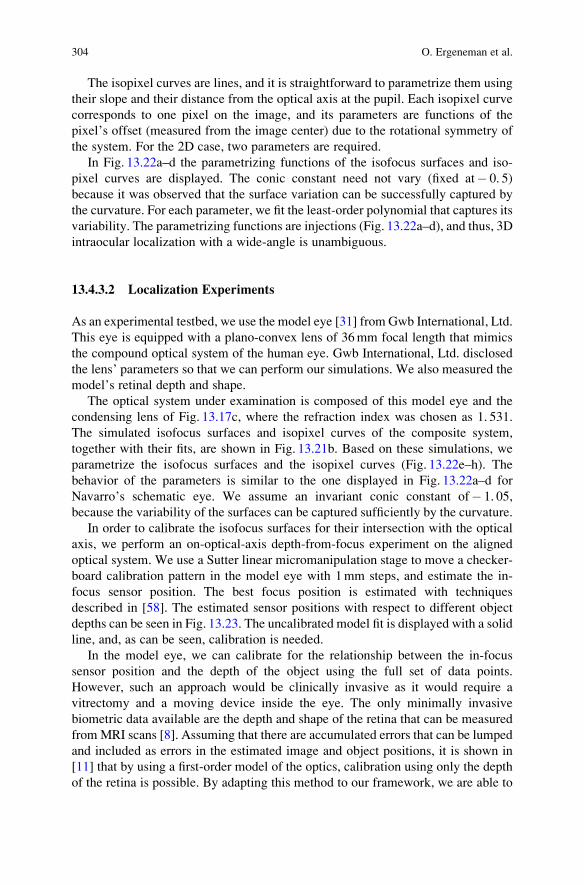
The isopixel curves are lines, and it is straightforward to parametrize them using
their slope and their distance from the optical axis at the pupil. Each isopixel curve
corresponds to one pixel on the image, and its parameters are functions of the
pixel’s offset (measured from the image center) due to the rotational symmetry of
the system. For the 2D case, two parameters are required.
In Fig. 13.22a–d the parametrizing functions of the isofocus surfaces and iso-
pixel curves are displayed. The conic constant need not vary (fixed at� 0. 5)
because it was observed that the surface variation can be successfully captured by
the curvature. For each parameter, we fit the least-order polynomial that captures its
variability. The parametrizing functions are injections (Fig. 13.22a–d), and thus, 3D
intraocular localization with a wide-angle is unambiguous.
13.4.3.2 Localization Experiments
As an experimental testbed, we use the model eye [31] from Gwb International, Ltd.
This eye is equipped with a plano-convex lens of 36mm focal length that mimics
the compound optical system of the human eye. Gwb International, Ltd. disclosed
the lens’ parameters so that we can perform our simulations. We also measured the
model’s retinal depth and shape.
The optical system under examination is composed of this model eye and the
condensing lens of Fig. 13.17c, where the refraction index was chosen as 1. 531.
The simulated isofocus surfaces and isopixel curves of the composite system,
together with their fits, are shown in Fig. 13.21b. Based on these simulations, we
parametrize the isofocus surfaces and the isopixel curves (Fig. 13.22e–h). The
behavior of the parameters is similar to the one displayed in Fig. 13.22a–d for
Navarro’s schematic eye. We assume an invariant conic constant of� 1. 05,
because the variability of the surfaces can be captured sufficiently by the curvature.
In order to calibrate the isofocus surfaces for their intersection with the optical
axis, we perform an on-optical-axis depth-from-focus experiment on the aligned
optical system. We use a Sutter linear micromanipulation stage to move a checker-
board calibration pattern in the model eye with 1mm steps, and estimate the in-
focus sensor position. The best focus position is estimated with techniques
described in [58]. The estimated sensor positions with respect to different object
depths can be seen in Fig. 13.23. The uncalibrated model fit is displayed with a solid
line, and, as can be seen, calibration is needed.
In the model eye, we can calibrate for the relationship between the in-focus
sensor position and the depth of the object using the full set of data points.
However, such an approach would be clinically invasive as it would require a
vitrectomy and a moving device inside the eye. The only minimally invasive
biometric data available are the depth and shape of the retina that can be measured
fromMRI scans [8]. Assuming that there are accumulated errors that can be lumped
and included as errors in the estimated image and object positions, it is shown in
[11] that by using a first-order model of the optics, calibration using only the depth
of the retina is possible. By adapting this method to our framework, we are able to
304 O. Ergeneman et al.
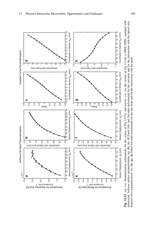
89
1011
1213
1415
9.0
9.5
10.0
10.5
11.0
11.5
12.0
12.5
13.0
13.5
89
1011
1213
1415
−32
−30
−28
−26
−24
−22
−20
−18
−16
−14
Intersection with Optical Axis (mm)
x 10
−2
Sen
sor
Dis
plac
emen
t d l
s (m
m)
Sen
sor
Dis
plac
emen
t d l
s (m
m)
−8−6
−4−2
02
46
8−1
−0.8
−0.6
−0.4
−0.20
0.2
0.4
0.6
0.81
Slope
−8−6
−4−2
02
46
8−1
.5−1
−0.50
0.51
1.5
Intersection with Pupil (mm)
Coo
rdin
ate
on S
enso
r d o
p (m
m)
Coo
rdin
ate
on S
enso
r d o
p (m
m)
68
1012
1416
1820
2224
7.5
8.0
8.5
9.0
9.5
68
1012
1416
1820
2224
−24
−22
−20
−18
−16
−14
−12
−10
Intersection with Optical Axis (mm)
x 10
−2
Sen
sor
Dis
plac
emen
t dls
(m
m)
Sen
sor
Dis
plac
emen
t dls
(m
m)
7.0
-10
-8-6
-4-2
02
46
810
-0.8
-0.6
-0.4
-0.20
0.2
0.4
0.6
0.8
−10
−8−6
−4−2
02
46
810
−4−3−2−1012345
Slope
Intersection with Pupil (mm)
Coo
rdin
ate
on S
enso
r d o
p (m
m)
Coo
rdin
ate
on S
enso
r d o
p (m
m)
Simulations for Navarro’s Eye [5]Curvature (mm−1)
Simulations for Model Eye [4]Curvature (mm−1
)
Isof
ocus
Sur
face
Par
amet
rizat
ion
Isop
ixel
Cur
ve P
aram
etriz
atio
n
ab
cd
ef
gh
Fig.13.22
toprow:Param
etrizationpolynomials
forthesystem
ofFig.13.21a,
andbo
ttom
row:forthesystem
ofFig.13.21b(#
IEEE
2009),reprintedwith
permission.Isofocussurfaceparam
etrization:(a),(b),(e),(f)Fitted2nd-and3rd-order
polynomialsforthecurvature
andfortheintersectionwiththeopticalaxis.
Isopixel
curveparam
etrization:(c),(d),(g),(h)Fitted3rd-order
polynomialsforthelineslopeandfortheintersectionwiththepupil
13 Wireless Intraocular Microrobots: Opportunities and Challenges 305

biometrically calibrate for the parameters of the polynomial that describes the
intersection of the isofocus surfaces with the optical axis. The resulting fit can be
seen in Fig. 13.23.
The remaining two parameters of the isofocus surfaces control the shape of the
isofocus surfaces but not their position. The condensing lens is designed to create a
flat aerial image of the retinal surface, and our experiments have shown that we can
use it to capture an overall sharp image of the model eye’s retina. Therefore, we
conclude that there exists an isofocus surface that corresponds to the retinal surface,
and we consider it as the first surface. From Fig. 13.21b we see that the first isofocus
surface does indeed roughly correspond to the retinal shape (mean error¼ 371 mm).
As a result, calibration for the conic constant and the curvature is not needed. If our
model was not accurately predicting the shape of the retina, then we would calibrate
the parameters of the first isofocus surface so that is has exactly the same shape as
the retina.
To estimate the validity of the presented wide-angle localization algorithm, we
consider points in the model eye for various angles with respect to the optical axis
and various distances from the pupil. In Fig. 13.24, the results using the proposed
wide-angle localization algorithm are displayed. For comparison, we also show the
results based on the paraxial localization algorithm presented in [11] for angles up
to 10 ∘ from the optical axis. The paraxial localization results deteriorate as the
angles increase. However, the localization method proposed here can be used for
regions away from the optical axis with high accuracy.
To fully control untethered devices, their position and orientation (i.e. their pose)
must be estimated. Until now, we have only addressed position estimation. For the
estimation of orientation, methods exist for perspective projection systems [19].
These methods work by projecting an estimate of the 6-DOF pose of a CAD model
7.5 8 8.5 9 9.5 10–34
–32
–30
–28
–26
–24
–22
–20
Sensor Position (mm)
Inte
rsec
tion
with
Opt
ical
Axi
s (m
m)
Uncalibrated ModelBiomedically Calibrated ModelFully Calibrated Model
Experimental Data
Fig. 13.23 Model fits for the function describing the intersection of the isofocus surfaces with the
optical axis. Biometric calibration errors: mean ¼ 159 mm, std ¼ 94mm (#IEEE 2009), reprinted
with permission
306 O. Ergeneman et al.

of the device on the image, based on a calibrated camera projection matrix, and then
adapting the estimate of the pose until projection agrees with the perceived image.
It may be possible to apply similar methods for pose estimation of intraocular
objects. However, the estimates of the pose would be projected on the image by
making use of the isopixel curves. This topic is left as future work.
13.5 Conclusions
In this chapter we considered three topics in the design and control of intraocular
microrobots. First, we discussed functional coatings – both for remote sensing and
targeted drug delivery. We developed a wireless oxygen sensor, and we presented a
method to deliver clot-busting tPA to retinal veins. Next, we discussed magnetic
control. We showed that it is technically feasible to generate sufficient forces to
puncture retinal veins. Finally, we showed that it is possible to visually track and
then localize intraocular microrobots with a single stationary camera. The localiza-
tion results can be utilized in the magnetic control system. The groundwork has
been laid, and it won’t be long before intraocular microrobots change the way that
the most difficult retinal procedures are done.
Acknowledgments This research is supported by the NCCR Co-Me of the Swiss National
Science Foundation. The authors would like to thank the many people that have contributed to
this research: Berk Yesin, Karl Vollmers, Zoltan Nagy, Brad Kratochvil, Ruedi Borer, Gorkem
Dogangil, Kamran Shamaei, and George Fagogenis, as well as Heike Hall from ETH Zurich, and
Mohammad K. Nazeeruddin from Ecole Polytechnique Federal de Lausanne. The authors also
would like to thank Justus Garweg, M.D. from the Swiss Eye Institute in Bern and Carsten
Framme, M.D. of the Inselspital Bern for their guidance on vitreoretinal applications for unteth-
ered microrobots.
−5
0
5
10
15
051015202530Distance from Pupil (mm)
Experimental DataWide-angle Localization Algorithm
10o 15o 20o5o
6um 188um 106um 284um 523um
247um 477um 348um 200um 285um
847um 119um 302um 504um
266um
551um 127um
177um 367um
239um
218um 266um
106um 373um
258um
72um 140um
193um 233um
262um
337um 89um
615um 214um
382um
Paraxial Localization Algorihm
25o 30o
(mm)Fig. 13.24 Localization
experiment showing the
validity of the proposed
algorithm. Errors:
mean¼ 282 mm,
std¼ 173 mm (#IEEE 2009),
reprinted with permission
13 Wireless Intraocular Microrobots: Opportunities and Challenges 307

References
1. Stereotaxis (2007). URL http://www.stereotaxis.com
2. Abbott, J.J., Ergeneman, O., Kummer, M.P., Hirt, A.M., Nelson, B.J.: Modeling magnetic
torque and force for controlled manipulation of soft-magnetic bodies. IEEE Trans. Robot. 23
(6), 1247–1252 (2007)
3. Abbott, J.J., Nagy, Z., Beyeler, F., Nelson, B.J.: Robotics in the small, part I: Microrobotics.
IEEE Robot. Automat. Mag. 14(2), 92–103 (2007)
4. Abbott, J.J., Peyer, K.E., Cosentino Lagomarsino, M., Zhang, L., Dong, L.X., Kaliakatsos,
I.K., Nelson, B.J.: How should microrobots swim? Int. J. Rob. Res. 28(11–12), 1434–1447
(2009)
5. Abolhassani, N., Patel, R., Moallem, M.: Needle insertion into soft tissue: A survey. Med.
Eng. Phys. 29, 413–431 (2007)
6. Amblard, F., Yurke, B., Pargellis, A., Leibler, S.: A magnetic manipulator for studying local
rheology and micromechanical properties of biological systems. Rev. Sci. Instrum. 67(3),
818–827 (1996)
7. Ascari, L., Bertocchi, U., Laschi, C., Stefanini, C., Starita, A., Dario, P.: A segmentation
algorithm for a robotic micro-endoscope for exploration of the spinal cord. In: IEEE Int. Conf.
Robotics and Automation, pp. 491–496 (2004)
8. Atchison, D.A., Pritchard, N., Schmid, K.L., Scott, D.H., Jones, C.E., Pope, J.M.: Shape of the
retinal surface in emmetropia and myopia. Invest. Ophthalmol. Vis. Sci. 46(8), 2698–2707
(2005)
9. Bach, M., Oschwald, M., Rover, J.: On the movement of an iron particle in a magnetic field.
Doc. Ophthalmol. 68, 389–394 (1988)
10. Bergeles, C., Fagogenis, G., Abbott, J.J., Nelson, B.J.: Tracking intraocular microdevices
based on colorspace evaluation and statistical color/shape information. In: Proc. IEEE Int.
Conf. Robotics and Automation, pp. 3934–3939 (2009)
11. Bergeles, C., Shamaei, K., Abbott, J.J., Nelson, B.J.: On imaging and localizing untethered
intraocular devices with a stationary camera. In: Proc. IEEE Int. Conf. on Biomedical
Robotics and Biomechatronics (2008)
12. Bergeles, C., Shamaei, K., Abbott, J.J., Nelson, B.J.: Wide-angle intraocular imaging and
localization. In: Int. Conf. Medical Image Computing and Computer Assisted Intervention,
vol. 1, pp. 540–548 (2009)
13. Bergeles, C., Shamaei, K., Abbott, J.J., Nelson, B.J.: Single-camera focus-based localization
of intraocular devices. IEEE Trans. Biomed. Eng. 57, 2064–2074 (2010)
14. Berkowitz, B., Wilson, C.: Quantitative mapping of ocular oxygenation using magnetic
resonance imaging. Magn. Reson. Med. 33(4), 579–581 (1995)
15. Cao, X., Lai, S., Lee, L.J.: Design of a self-regulated drug delivery device. Biomed. Micro-
devices 3(2), 109–118 (2001)
16. Davis, S.P., Landis, B.J., Adams, Z.H., Allen, M.G., Prausnitz, M.R.: Insertion of micronee-
dles into skin: Measurement and prediction of insertion force and needle fracture force.
J. Biomech. 37, 1155–1163 (2004)
17. Dogangil, G., Ergeneman, O., Abbott, J.J., Pane, S., Hall, H., Muntwyler, S., Nelson, B.J.:
Toward targeted retinal drug delivery with wireless magnetic microrobots. In: Proc. IEEE/RSJ
Int. Conf. on Intelligent Robots and Systems, pp. 1921–1926 (2008)
18. Doignon, C., Graebling, P., de Mathelin, M.: Real-time segmentation of surgical instruments
inside the abdominal cavity using a joint hue saturation color feature. Real-Time Imaging 11
(5-6), 429–442 (2005)
19. Drummond, T., Cipolla, R.: Real-time visual tracking of complex structures. IEEE Trans.
Pattern Anal. Mach. Intell. 24, 932–946 (2002)
20. Ens, J., Lawrence, P.: An investigation of methods for determining depth from focus. IEEE
Trans. Pattern Anal. Mach. Intell. 15(2), 97–108 (1993)
308 O. Ergeneman et al.

21. Ergeneman, O., Dogangil, G., Kummer, M.P., Abbott, J.J., Nazeeruddin, M.K., Nelson, B.J.:
A magnetically controlled wireless optical oxygen sensor for intraocular measurements. IEEE
Sens. J. 8(1), 29–37 (2008)
22. Escudero-Sanz, I., Navarro, R.: Off-axis aberrations of a wide-angle schematic eye model.
J. Opt. Soc. A. 16(8), 1881–1891 (1999)
23. FCI Ophthalmics: (2009) S5. 7010 planoconcave lens [Online]. Available: http://www.fci-
ophthalmics.com/html/retina.html#lenses
24. Furlani, E.P.: Permanent Magnet and Electromechanical Devices. Academic Press,
San Diego, California (2001)
25. Galloway, N.R., Amoaku, W.M.K., Galloway, P.H., Browning, A.C.: Common Eye Diseases
and their Management, third edn. Springer, London (2005)
26. Geroski, D.H., Edelhauser, H.F.: Drug delivery for posterior segment eye disease. Invest.
Ophthalmol. Vis. Sci. 41(5), 961–964 (2000)
27. Ghazi, N.G., Noureddine, B.N., Haddad, R.S., Jurdi, F.A., Bashshur, Z.F.: Intravitreal tissue
plasminogen activator in the management of central retinal vein occlusion. Retina 23,
780–784 (2003)
28. Gillies, G.T., Ritter, R.C., Broaddus, W.C., Grady, M.S., Howard, M.A. III, McNeil, R.G.:
Magnetic manipulation instrumentation for medical physics research. Rev. Sci. Instrum.
65(3), 533–562 (1994)
29. Grady, M.S., Howard, M.A. III, Molloy, J.A., Ritter, R.C., Quate, E.G., Gillies, G.T.:
Nonlinear magnetic stereotaxis: Three-dimensional, in vivo remote magnetic manipulation
of a small object in canine brain. Med. Phys. 17(3), 405–415 (1990)
30. Gupta, P.K., Jensen, P.S., de Juan, E. Jr.: Surgical forces and tactile perception during retinal
microsurgery. In: Proc. Int. Conf. Med. Image Comput. and Comput.-Assisted Intervention,
pp. 1218–1225 (1999)
31. Gwb International, Ltd.: (2009) Model Eye (2mm pupil) [Online]. Available: http://www.
gwbinternational.com/model_eye.htm
32. Ishiyama, K., Arai, K.I., Sendoh, M., Yamazaki, A.: Spiral-type micro-machine for medical
applications. J. Micromechatronics 2(1), 77–86 (2003)
33. Iwase, E., Shimoyama, I.: Multistep sequential batch assembly of three-dimensional ferro-
magnetic microstructures with elastic hinges. J. Microelectromech. Syst. 14(6), 1265–1271
(2005)
34. Jagtap, A.D., Riviere, C.N.: Applied force during vitreoretinal microsurgery with handheld
instruments. In: Proc. IEEE Int. Conf. Engineering in Medicine and Biology Society,
pp. 2771–2773 (2004)
35. Jiles, D.: Introduction to Magnetism and Magnetic Materials. Chapman and Hall, London
(1991)
36. Khamesee, M.B., Kato, N., Nomura, Y., Nakamura, T.: Design and control of a microrobotic
system using magnetic levitation. IEEE/ASME Trans. Mechatron. 7(1), 1–14 (2002)
37. Kirschkamp, T., Dunne, M., Barry, J.C.: Phakometric measurement of ocular surface radii of
curvature, axial separations and alignment in relaxed and accommodated human eyes.
J. Ophth. Phys. Opt. 24(2), 65–73 (2004)
38. Kummer, M.P., Abbott, J.J., Kratochvil, B.E., Borer, R., Sengul, A., Nelson, B.J.: OctoMag:
An electromagnetic system for 5-DOF wireless micromanipulation. In: Proceedings of the
International Conference on Robotics and Automation (2010)
39. Kummer, M.P., Abbott, J.J., Vollmers, K., Nelson, B.J.: Measuring the magnetic and hydro-
dynamic properties of assembled-MEMS microrobots. In: Proc. IEEE Int. Conf. Robotics and
Automation, pp. 1122–1127 (2007)
40. Lakowicz, J.R.: Principles of Fluorescence Spectroscopy, 2nd edn. Kluwer Academic/Plenum
Publishers (1999)
41. Leng, T., Miller, J.M., Bilbao, K.V., Palanker, D.V., Huie, P., Blumenkranz, M.S.: The chick
chorioallantoic membrane as a model tissue for surgical retinal research and simulation.
Retina 24(3), 427–434 (2004)
13 Wireless Intraocular Microrobots: Opportunities and Challenges 309

42. Leventon, M.E., Grimson, W.E.L., Faugeras, O.: Statistical shape influence in geodesic active
contours. IEEE Int. Conf. Computer Vision and Pattern Recognition 1 (2000)
43. M. K. Tameesh et al.: Retinal vein cannulation with prolonged infusion of tissue plasminogen
activator (t-PA) for the treatment of experimental retinal vein occlusion in dogs.
Am. J. Ophthalmol. 138(5), 829–839 (2004)
44. Mathieu, J.B., Beaudoin, G., Martel, S.: Method of propulsion of a ferromagnetic core in the
cardiovascular system through magnetic gradients generated by an MRI system. IEEE Trans.
Biomed. Eng. 53(2), 292–299 (2006)
45. Meeker, D.C., Maslen, E.H., Ritter, R.C., Creighton, F.M.: Optimal realization of
arbitrary forces in a magnetic stereotaxis system. IEEE Trans. on Magnetics 32(2),
320–328 (1996)
46. Mejia-Barbosa, Y., Malacara-Hernandez, D.: A review of methods for measuring corneal
topography. J. Opt. Vis. Sci. 78(4), 240–253 (2001)
47. Mitchell, B., Koo, J., Iordachita, I., Kazanzides, P., Kapoor, A., Handa, J., Hager, G., Taylor,
R.: Development and application of a new steady-hand manipulator for retinal surgery.
In: Proc. IEEE Int. Conf. Robotics and Automation, pp. 623–629 (2007)
48. Mitra, A.K.: Ophthalmic Drug Delivery Systems. Marcel Dekker Inc., New York (2003)
49. Nagy, Z., Ergeneman, O., Abbott, J.J., Hutter, M., Hirt, A.M., Nelson, B.J.: Modeling
assembled-MEMS microrobots for wireless magnetic control. In: Proc. IEEE Int. Conf.
Robotics and Automation, pp. 874–879 (2008)
50. Park, J.H., Allen, M.G., Prausnitz, M.R.: Polymer microneedles for controlled-release drug
delivery. Pharm. Res. 23(5), 1008–1018 (2006)
51. Ratner, B.D., Hoffman, A.S., Schoen, F.J., Lemons, J.E. (eds.): Biomaterials Science:
An Introduction to Materials in Medicine, second edn. Elsevier Academic Press (2004)
52. Riviere, C.N., Ang, W.T., Khosla, P.K.: Toward active tremor canceling in handheld
microsurgical instruments. IEEE Trans. on Robotics and Automation 19(5), 793–800 (2003)
53. Shahid, H., Hossain, P., Amoaku, W.M.: The management of retinal vein occlusion:
Is interventional ophthalmology the way forward? Br. J. Ophthalmol. 90, 627–639 (2006)
54. Shi, Y., Karl, W.C.: Real-time tracking using level sets. IEEE Int. Conf. Computer Vision and
Pattern Recognition 2, 34–41 (2005)
55. Shonat, R., Kight, A.: Oxygen tension imaging in the mouse retina. Ann. Biomed. Eng. 31,
1084–1096 (2003)
56. Smith, G., Atchison, D.A.: The eye and visual optical instruments. Cambridge University
Press, Cambridge (1997)
57. Snead, M.P., Rubinstein, M.P., Jacobs, P.M.: The optics of fundus examination.
Sur. Ophthalm. 36(6), 439–445 (1992)
58. Sun, Y., Duthaler, S., Nelson, B.J.: Autofocusing in computer microscopy: selecting the
optimal focus algorithm. J. Microsc. Res. Tech. 65(3), 139–149 (2004)
59. Syms, R.R.A., Yeatman, E.M., Bright, V.M., Whitesides, G.M.: Surface tension-powered
self-assembly of microstructures—the state-of-the-art. J. Microelectromech. Syst. 12(4),
387–417 (2003)
60. Tang, W.M., Han, D.P.: A study of surgical approaches to retinal vascular occlusions.
Arch. Ophthalmol. 118, 138–143 (2000)
61. Tjoa, M., Krishnan, S., Kugean, C., Wang, P., Doraiswami, R.: Segmentation of clinical
endoscopic image based on homogeneity and hue. IEEE Int. Conf. Engineering in Medicine
and Biology pp. 2665–2668 (2001)
62. Tunay, I.: Modeling magnetic catheters in external fields. In: Proc. IEEE Int. Conf. Engineer-
ing in Medicine and Biology Society, pp. 2006–2009 (2004)
63. Volk, D.A.: Indirect ophthalmoscopy lens for use with split lamp or other biomicroscope
(1998). U.S. Patent 5,706,073
64. White, F.M. (ed.): Fluid Mechanics, 3rd edn. McGraw-Hill Inc., New York (1994)
65. Yang, G., Gaines, J.A., Nelson, B.J.: Optomechatronic design of microassembly systems for
manufacturing hybrid microsystems. IEEE Trans. Ind. Electron. 52(4), 1013–1023 (2005)
310 O. Ergeneman et al.

66. Yesin, K.B., Vollmers, K., Nelson, B.J.: Modeling and control of untethered biomicro-
robots in a fluidic environment using electromagnetic fields. Int. J. Rob. Res. 25(5-6),
527–536 (2006)
67. Zhang, L., Abbott, J.J., Dong, L.X., Kratochvil, B.E., Bell, D., Nelson, B.J.: Artificial bacterial
flagella: Fabrication and magnetic control. Appl. Phys. Lett. 94(064107) (2009)
13 Wireless Intraocular Microrobots: Opportunities and Challenges 311